PREMIER AD INSTALLATION MANUAL. Software:31/3/04 & LC6 CONTENTS
|
|
|
- Angela Whitehead
- 5 years ago
- Views:
Transcription

1 INSTALLATION MANUAL
2 CONTENTS 1. PREMIER AD OVERVIEW SETTING THE DEVICE ADDRESS (DETECTORS, CALL POINTS & SOUNDERS) 2. LIST OF COMPATIBLE EQUIPMENT SUPPORTED SOUNDER TYPES & THEIR APPLICATIONS 3. INTRODUCTION THE PCBS 3.2 USING THIS MANUAL 3.3 ABOUT THE PREMIER AD FACP & INTEGRAL PSE 3.4 DESIGNING THE SYSTEM 3.5 EQUIPMENT GUARANTEE 4. FIRST FIX GUIDELINES RECOMMENDED CABLE TYPES AND THEIR LIMITATIONS 4.2 MAINS WIRING RECOMMENDATIONS 4.3 SOUNDER CIRCUIT WIRING DIAGRAM 4.4 ADDRESSABLE LOOP WIRING DIAGRAM 4.5 SPECIFIC DEVICE WIRING INSTRUCTIONS 4.6 AUXILIARY INPUT WIRING EXAMPLES 4.7 AUXILIARY OUTPUT WIRING (VOLTAGE FREE CHANGEOVER CONTACTS) 5. MOUNTING THE FIRE ALARM PANEL PLANNING CABLE ENTRY 5.2 FIXING THE BACKBOX TO THE WALL 6. CONNECTING MAINS & BATTERY POWER CONNECTING MAINS POWER 6.2 CONNECTING THE BATTERIES 7. FIELD DEVICE TERMINATION TERMINATING THE DETECTION AND ALARM (SOUNDER) CIRCUITS 7.2 AUXILIARY INPUT AND OUTPUT TERMINATIONS 8. DESIGNING THE SYSTEM & CONFIGURING THE FACP LOOP CONTENTS FAULT FINDING 8.2 ADDRESS - ZONE TABLE 9. ZONE DISABLEMENT WHY USE ZONE DISABLEMENT 9.2 TO PROGRAM A ZONE (OR SOUNDERS) AS DISABLED 10. TEST MODE WHY USE TEST MODE 10.2 TO PROGRAM ZONE IN TEST 10.3 TO PROGRAM SOUNDER CIRCUITS IN TEST MODE 11. GENERAL FAULT FINDING COMMON FAULT 11.2 ZONE FAULTS 11.3 SUPPLY FAULT 11.4 EARTH FAULTS 11.5 DOUBLE ADDRESS 11.6 SYSTEM FAULT 11.7 PRE-ALARM 11.8 SOUNDER FAULTS 11.9 LOOP WIRING FAULTS 12. STANDBY BATTERY REQUIREMENTS STANDBY BATTERY CALCULATION 13. PCB TERMINATION CONNECTIONS CONNECTIONS 13.2 FUSES 14. CONTROL PANEL ELECTRICAL SPECIFICATIONS ENCLOSURE SPECIFICATIONS 14.2 ELECTRICAL SPECIFICATIONS Approved Document No: GLT.MAN-105 PAGE 2
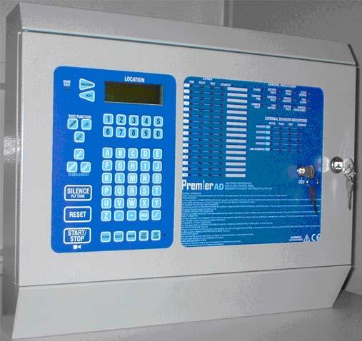
3 1.PREMIER AD OVERVIEW The Premier AD is a 2-loop analogue addressable fire alarm control panel designed to EN54 part 2 & 4. It has 2 addressable loops, each capable of having 126 devices, and also 4 independently operating sounder circuits. It has been designed to give the advantages of an addressable system, with the simplicity of a conventional system. To help achieve this, the Premier AD uses its LEDs as the Primary source of information, so in most cases, there is no reason to look at the screen, or access any menus. The screen is simply there to identify loop device fault locations, and to help in setting up the panel. To simplify commissioning further, there is no zone allocation programming. Instead each loop is split into 8 zones, and each device is assigned to a zone by the address set with its 8 way dip switch. Address 1-16 Zone 1 (Zone 9 on loop 2) Address Zone 2 (Zone 10 on loop 2) Address Zone 3 (Zone 11 on loop 2) Address Zone 4 (Zone 12 on loop 2) Address Zone 5 (Zone 13 on loop 2) Address Zone 6 (Zone 14 on loop 2) Address Zone 7 (Zone 15 on loop 2) Address Zone 8 (Zone 16 on loop 2) The Premier AD has 4 sounder circuits, which are always configured as common sounders. They will activate with an alarm from any zone. The loop outputs (loop powered sounders, & sounder circuit controllers) can be set up as zonal, or common. If the sounder is in a zone that contains a detector or input module, then that sounder will be zonal, and will only activate with an alarm in that zone. If the sounder is in a zone that only contains output devices, then it will be common, and will activate with any alarm. The exception to this rule is a priority Call Point, which will start all sounders, even if they are set up as zonal. 1.1 SETTING THE DEVICE ADDRESS (DETECTORS, CALL POINTS & SOUNDERS) The device address is set with a dip switch on the rear of the device ON The address setting is binary, with the ON position being binary 0, and the OFF position being binary 1. Switch 8 is not used for setting the address, but sometimes has a devise specific function. (check instructions that came with the device) If you are not familiar with binary, check the table on page 17, or use the following rule: Switch 7 off = add 64, Switch 6 off = add 32, Switch 5 off = add 16, Switch 4 off = add 8, Switch 3 off = add 4, Switch 2 off = add 2, Switch 1 off = add 1. The example shown would be: switches 6, 4 & 1 = = Address 41 LIMITATIONS OF PRESET ZONE ALLOCATION The main disadvantage of this method of zone allocation is the maximum zone capacity of 16 devices. If a zone has more than 16 devices it will need to be split into smaller zones. Similarly, a zone with only one device would leave 15 empty addresses on that zone. This will not cause a problem if it is considered at the system design stage. Approved Document No: GLT.MAN-105 PAGE 3
4 2. LIST OF COMPATIBLE EQUIPMENT Stock No Product Code Device PR-AD Premier AD Fire Alarm Panel PREP-AD Premier AD Repeater FEAI2000 Fyreye Addressable Ionisation Detector FEAO2000 Fyreye Addressable Optical Detector FEAH2000 Fyreye Addressable Heat Detector FEAHH2000 Fyreye Addressable High Temperature Heat Detector FEAOH2000 Fyreye Addressable Multi-Point Detector FECO2000 Fyreye Addressable Carbon Monoxide Detector FE-CB Fyreye Common Base FEA-RB Fyreye Addressable Relay Base FE-IB Fyreye Addressable Loop Isolator Base FEA-SB Fyreye Addressable Sounder Base FEA-ISB Fyreye Addressable Isolator Sounder Base ZT-MCP/AD Zeta Addressable Call Point ZT-MCP/AD/WP Zeta Weatherproof Addressable Call Point ZIU Zeta Input Unit ZIOU Zeta Input Output Unit ZSCC Zeta Sounder Control Module ZT-ZM Zeta Zone Monitor Unit ZAMT Zeta Addressable Maxitone Sounder ZAMD Zeta Addressable Miditone Sounder ZAST Zeta Addressable Securetone Sounder ZTA/LE2 Zeta Addressable Remote Led Indicator ZTA-FR50 Fyreye Addressable Reflective Beam Detector 50m ZTA-FR100 Fyreye Addressable Reflective Beam Detector 100m FE+50/AD Fyreye Plus Addressable Aspiration Detector ZMT/8 Zeta Conventional Maxitone Sounder ZMD/8 Zeta Conventional Miditone Sounder ZST/8 Zeta Conventional Securetone Sounder ZIDC/10R Zeta Conventional Megatone Sounder ZFL2RR Zeta Conventional Flasher ZLT/8RR Zeta Conventional Flasher Sounder ZTB6B/24 Zeta Conventional 6 Bells ZTB8B Zeta Conventional 8 Bells 2.1 SUPPORTED SOUNDER TYPES & THEIR APPLICATIONS The Premier AD supports 4 general sounder types; conventional, addressable, addressable sounder controller, and associated sounders. All types have advantages & disadvantages. Sounder type Advantage Disadvantage Conventional Wide range of devices Devices tend to be cheaper. Immediate start / stop No quiescent current Addressable Associated (sounderbase) Addressable Sounder Circuit Controller No Extra Cabling Sounders can be configured as zonal No Extra Cabling Doesn t occupy Device Address Can have more than 32 per loop Wide range of devices Devices tend to be cheaper. Can add many sounder circuits to system Sounder circuit can be set as zonal Needs extra cabling Always configured as common sounders Tends to be more expensive Maximum 32 per loop for quick start/stop Quiescent current high Uses device address. 4-8 second start & stop time. Always configured as common sounders Needs detector present to operate. Does not operate during sounder test mode Needs Extra Cabling. Needs External PSU Maximum 32 per loop for quick start/stop Quiescent current high Uses device address. Approved Document No: GLT.MAN-105 PAGE 4
5 3.INTRODUCTION THIS FIRE ALARM CONTROL PANEL IS CLASS 1 EQUIPMENT AND MUST BE EARTHED This equipment must be installed and maintained by a qualified and technically experienced person. 3.1 HANDLING THE PCBS If the PCBs are to be removed to ease fitting the enclosure and cables, care must be taken to avoid damage by static. The best method is to wear an earth strap, but touching any earth point (eg building plumbing) will help to discharge any static. Hold PCBs by their sides, avoiding contact with any components. Always handle PCBs by their sides and avoid touching the legs of any components. Keep the PCBs away from damp dirty areas, e.g. in a small cardboard box. 3.2 USING THIS MANUAL This manual explains, in a step-by-step manner, the procedure for the installation of the Premier AD Range of Fire Alarm Control Panels. For full operational and maintenance information, please refer to document GLT.MAN-106 (USER MANUAL, MAINTENANCE GUIDE & LOG BOOK). It also contains a System set-up table, and Installation Certificate, that must be completed by the Commissioning Engineer prior to system handover. Unlike the User Manual, this Installation Manual must not be left accessible to the User. 3.3 ABOUT THE PREMIER AD FIRE ALARM CONTROL PANEL & INTEGRAL PSE The PREMIER AD Fire alarm control panel is a two loop analogue addressable Fire Alarm Control Panel, with the loops split into 16 Zones. It has 4 sounder output circuits each capable of supplying 250mA. It has a set of fire relay contacts (voltage free) rated at 1A SELV. It has a set of fault relay contacts (voltage free) rated at 1A SELV. This relay is normally powered to allow a fault output in the case of total power failure. It has a class change connection to allow remote activation of the sounders. (not required by EN54-2) It has the ability to disable any zone or any of the sounder circuits. It has a one man test mode, which resets the zone in test after 8 seconds.(en54 option with requirements) It has a maximum battery capacity of 7 Ah. It will operate in ambient temperatures of 5 to 40 o C It will operate in a relative humidity of up to 93% (non condensing) It will withstand vibrations between 5 & 150 Hz It has a maximum capacity of 32 devices per zone The PSE is linear, with a 1.5A output at system voltage (18-32V) The mains supply is filtered before entering the transformer. The charger & battery are both fused at 2.5A (time delay) The PSE will draw a maximum of 25uA from the battery in the event of mains failure. (the FACP will continue to take around 60mA) The FACP & PSE should be maintained as described in section 3 of the User Manual, Maintenance Guide & Log Book. 3.4 DESIGNING THE SYSTEM This manual is not designed to teach Fire Alarm System design. It is assumed that the System has been designed by a competent person, and that the installer has an understanding of Fire Alarm System components and their use. We strongly recommend consultation with a suitably qualified, competent person regarding the design of the Fire Alarm System. The System must be commissioned and serviced in accordance with our instructions and the relevant National Standards. Contact the Fire Officer concerned with the property at an early stage in case he has any special requirements. If in doubt, read BS 5839: Pt 1: 2002 Fire Detection and Alarm Systems for buildings (Code of Practice for System Design, Installation, commissioning and maintenance) available from the BSI, or at your local reference library. 3.5 EQUIPMENT GUARANTEE Approved Document No: GLT.MAN-105 PAGE 5
6 If this equipment is not fitted and commissioned according to our guidelines, and the relevant National Standards, by an approved and competent person or organisation, the warrantee may become void. 4. FIRST FIX All wiring must be installed to meet BS5839: Pt1: 2002 and BS 7671 (Wiring Regs) standards. Other National standards of fire alarm system installation should be adhered to where applicable. 4.1 RECOMMENDED CABLE TYPES AND THEIR LIMITATIONS Screened cables should be used throughout the installation to help shield the Panel from outside interference and ensure EMC compatibility. The two categories of cable according to BS5839: Pt1: 2002, Clause 26 Fire Detection and Alarm Systems for Buildings (Code of Practice for System Design, Installation and Servicing) are: Standard fire resisting cable to PH30 classification of EN Enhanced fire resisting cable to PH120 classification of EN (Note that all cables should be at least 1mm 2 cross section On the Premier AD Panel the general recommendation would be to use standard fire resistant cable, such as Firetuff, FP200 or an equivalent. These cables are screened, and will provide good ECM shielding when properly grounded at the panel. Certain system specifications may demand the use of a particular type of cable and due regard should be paid to this fact. Depending on the environment, the cables may need mechanical protection (such as a conduit). 4.2 MAINS WIRING RECOMMENDATIONS The Mains supply to the FACP is fixed wiring, using Fire resisting 3-core cable (Between 1 mm² and 2.5mm²) or a suitable 3-conductor system, fed from an isolating double pole switch fused spur, fused at 3A. IT SHOULD NOT BE CONNECTED THROUGH AN RCD. This should be secure from unauthorised operation and be marked FIRE ALARM: DO NOT SWITCH OFF. The supply must be exclusive to the Fire Panel. MAKE SURE ANY SPARE ENTRY HOLES ARE COVERED WITH THE GROMMETS PROVIDED For information on how to connect Mains to the Panel s Power Supply PCB, see page 8. Also refer to rating information on the mains cover inside the FACP 4.3 CONVENTIONAL SOUNDER CIRCUIT WIRING DIAGRAM SND+ SND- SOUNDER SOUNDER SOUNDER SOUNDER K End of Line Resistor Note: If non-polarised alarm devices (eg some types of old mechanical bell, or a relay) are used, then a diode will have to be placed in line with the device to enable fault monitoring. They may also need a back EMF protection diode. (symptoms: Chattering sounder relays that don t turn off). SND+ SND- CONNECTOR BLOCK POLARISING DIODE BELL BELL BELL RELAY NC CM NO 10K End of Line Resistor BACK EMF DIODE Approved Document No: GLT.MAN-105 PAGE 6
7 -R L1IN L1O UT L2 -R L1IN L1OUT L2 -R L1IN L1OUT L2 PREMIER AD INSTALLATION MANUAL. 4.4 ADDRESSABLE LOOP WIRING DIAGRAM The Premier AD comes with two addressable loops. Addressable detectors, addressable call points, addressable loop powered sounders and several other interface units can be connected to these loops. A MAXIMUM OF 126 DEVICES CAN BE CONNECTED TO EACH LOOP. Side A +ve EARTH EARTH EARTH Side A -ve FYREYE ADDRESSABLE DETECTORS ADDRESSABLE CALL POINT + -- ADDRESSABLE LOOP POWERED SOUNDER Side B +ve Side B -ve -R L1IN L1O UT L2 EARTH -R L1IN L1OUT L2 EARTH -R L1IN L1OUT L IN OUT EARTH FYREYE ISOLATING BASE Note that some Devices (for example, a sounder controller circuit) may require a separate 24 volt supply to operate. FYREYE ADDRESSABLE DETECTORS A maximum of 32 loop-powered addressable sounders are permitted on the loop. There is no limit (loop load permitting) to the number of sounder bases that can be connected to a loop. On the Premier AD Panel, all Sounder Bases are always configured as common sounders. Short circuit isolators should be used to prevent loosing the whole loop in the event of a single short circuit fault. They should be fitted to each zone boundary, such that any short circuit will only affect the devices in 1 zone. The termination of each detection circuit must be as indicated on the main PCB (See page 15). The Earthing of the cable screens should be as shown on page 9 Pre-Commissioning Cable Checks 1. +ve in to +ve out less than 24 ohms 2. -ve in to -ve out less than 24 ohms (may need to temporarily disable isolators to measure) 3. +ve to ve greater than 500k ohm 4. +ve to Earth greater than 1M ohm. 5. -ve to Earth greater than 1M ohm. 6. +ve to ve less than 50 mv pickup (on AC & DC scales) Approved Document No: GLT.MAN-105 PAGE 7
8 SPECIFIC DEVICE WIRING INSTRUCTIONS: Fyreye Common Base FE-CB LOOP + IN LOOP + OUT Fyreye Addressable Detector Relay Base FEA-RB LOOP + IN LOOP + OUT EARTH EARTH L2 L2 L1OUT L1OUT C RELAY OUTPUT -R L1IN -R L1IN LOOP - IN LOOP - OUT LOOP - IN LOOP - OUT Fyreye Loop Isolator Base FE-IB Note that on the Fyreye Loop Isolator Base, the loop wiring connects to the terminal block on the PCB and NOT to the Base Spring Screws. EARTH The terminals are marked + & - in, and +,- &- out. L IN OUT L1OUT The second ve contact can be used during commissioning to check the loop integrity. LOOP - IN -R L1IN LOOP - OUT (Connect the in to the spare out. Repeat for all isolators. Measure ve line resistance with a DVM. Return the in cable to its original terminal block.) LOOP + IN LOOP + OUT Fyreye Addressable Sounder Base FEA-SB Zeta Glass Manual Call Point (Resetable) ZT-MCP/AD (/R) (43-002) LOOP + IN LOOP + OUT EARTH L2 L1OUT -R L1IN LOOP - IN LOOP - OUT LOOP - IN LOOP - OUT LOOP + IN LOOP + OUT Approved Document No: GLT.MAN-105 PAGE 8
9 Zeta Input Unit ZIU Zeta Input Output Unit ZIOU K EOL 0.5W N/O CM N/C 47K EOL 0.5W LOOP - IN LOOP - OUT LOOP + IN LOOP + OUT LOOP - IN LOOP - OUT LOOP + IN LOOP + OUT Zeta Sounder Controller Circuit ZSCC Zeta Zone Monitoring Unit +1A PSU ZT-ZM Volt Supply 24 Volt Supply K End of Line Resistor 47K End of Line Resistor LOOP - IN LOOP - OUT LOOP - IN LOOP - OUT LOOP + IN LOOP + OUT LOOP + IN LOOP + OUT Approved Document No: GLT.MAN-105 PAGE 9
10 4.6 AUXILIARY INPUT WIRING EXAMPLES There is one non-latching auxiliary input connection on the Fire Alarm Panel. Class Change Input (CC): This will energise all alarm outputs continuously when the CC terminals are shorted together. (This includes the 4 conventional sounder outputs & any loop powered sounders.) Typical auxiliary input wiring options CLASS CLASS CHANGE CM NO AUX FIRE RELAY CHANGE 2nd Fire Alarm The termination for the above inputs must be as indicated on the main PCB (See page 15). The Earthing of the cable screens should be as shown on page AUXILIARY OUTPUT WIRING (VOLTAGE FREE CHANGEOVER CONTACTS) Auxiliary Fire Output (AUX): Changes over in any fire condition, and be used for driving local fire fighting equipment such as sprinkler systems, magnetic door holders, air conditioning shut off, etc. Fault Output (FAULT): This Output is energised in the quiescent condition. In a fault condition, the output relay turns off, to ensure failsafe operation even in the event of total power loss. That is, the normally open contact will be closed when there is no fault, and open when there is a fault. This should be taken into account when any device is connected to the fault relay. Typical auxiliary output wiring NO CM NC FAULT RELAY Trigger I/P NOTE: THE NC CONTACT IS OPEN WHEN THERE IS NO FAULT. FAULT INDICATION DEVICE The fault relay is used to connect to a remote indication device Trigger I/P AUTO- DIALER The fire relay can be used to connect to various devices which are activated on a fire alarm. Eg. Auto dialer, magnetic door release (24V), sprinkler system etc. NO CM NC FIRE RELAY The termination for the above inputs must be as indicated on the main PCB (See page 15). The Earthing of the cable screens should be as shown on page 9. Approved Document No: GLT.MAN-105 PAGE 10
11 5. MOUNTING THE FIRE ALARM PANEL It is recommended that the panels door be removed to avoid accidental damage. Also, the termination PCB could be removed and stored in a safe place, while fixing the back box to the wall. 5.1 PLANNING CABLE ENTRY Fig.2 below shows the location of the cable entries to facilitate planning of wiring (home runs) to be brought to the panel. The grommets can be easily removed by a push from inside the control panel box. If a grommet is removed, fill the hole with a brass cable gland. If any knockout is removed, but subsequently not used, it should be covered up. The 230Va.c. Mains cable must be fed into the enclosure via one of the cable entries at the top right corner of the back box. (Refer to Connecting the Mains on Page 8). 5.2 FIXING THE BACK BOX TO THE WALL Figure 2: Plan view inside the enclosure without PCBs. Side view for surface installation. 255mm 395mm 406mm 480mm 100mm Fix the enclosure to the wall using the three mounting holes provided. Check the build & condition of the wall to decide a suitable screw fixing. The mounting holes are designed for No 8 roundhead or countersunk woodscrews (or similar). Remove any debris from the enclosure. Take care not to damage the FACP during installation. Approved Document No: GLT.MAN-105 PAGE 11
12 6 CONNECTING MAINS & BATTERY POWER 6.1 CONNECTING THE MAINS POWER INLET MAINS SUPPLY The panel should be connected to V AC by a 3A rated spur to the fuse box with 1mm 2 to 2.5mm 2 3-core cable. Nothing else should be connected to this supply. The cable should be fire resistant The Live, Earth and Neutral connections are marked on the PCB. The Mains is protected by a quick blow 20mm 2A HBC fuse. (Also known as HRC) The incoming mains cable should be kept separate from the zone cables to help minimise mains interference. Once the mains is connected, the protective cover should be replaced BEFORE turning on the mains power. This will minimise the chance of electric shock from the PCB. MAKE SURE ANY SPARE ENTRY HOLES ARE COVERED WITH THE PLASTIC GROMMETS PROVIDED It is advisable to apply power to the panel before connecting any devices, to check for correct operation, and to familiarise yourself with the fire alarm panels controls. Figure 3: Power Supply PCB layout and Mains connection details 6.2 CONNECTING THE BATTERIES Although there are many sizes of suitable battery, the sizes we usually recommend for the Premier AD are 12V 7Ah, LINK WIRE Figure 4: Battery location and connection details To calculate the exact requirement, use the equation in section 10, BATTERY CONNECTIONS The two batteries are wired in series. The +ve of one battery is connected to the red battery lead. The ve of the other battery is connected to the black battery lead. The ve of the first battery is connected to the +ve of the second battery using the link wire supplied. When fitting the batteries, take care not to damage the temperature monitoring thermistors. See figure 4a overleaf. Approved Document No: GLT.MAN-105 PAGE 12
13 CONN27 CONN27 LO OP 1A SND 1 LO OP 1B SND 2 LO OP 2 A SND 3 LO OP 2 B SND CLASS CH - + SERIAL REPAETER AUX SUP CO NN19 CONN12 CONN20 CO NN13 CONN21 CO NN14 CONN22 CONN18 CONN15 CONN16 CO NN17 CONN28 CO NN24 CONN25 CONN23 CONN4 CONN30 CONN2 AC AC CONN29 CONN6 PREMIER AD INSTALLATION MANUAL. THERMISTOR Figure 4a:Thermistor location The thermistor is used to prevent overcharging the batteries in high ambient temperatures. 7. FIELD DEVICE TERMINATION 7.1 TERMINATING THE ADDRESSABLE LOOPS AND ALARM (SOUNDER) CIRCUITS. Brass Glands INLET MAINS SUPPLY All cables entering the enclosure should have brass cable glands, which will ensure a good ground to the steel EMC cable grounding plate. 47W/7 47W/7 47W/7 47W/7 MAKE SURE ANY SPARE ENTRY HOLES ARE COVERED WITH THE GROMMETS PROVIDED FIRE RELAY FAULT RELAY NO CM NC NO CM NC 47W/7 47W/7 + - BATTERY MAINS FUSE 3A H BC CERAMIC LIVE NEUT- EARTH RAL The Detector and Sounder circuits should be connected to the appropriate connector block on the Termination PCB as shown in Figure 6 below. All screens should be terminated at the brass earthing strip as shown in Figure 6 (For detailed detector and alarm circuit wiring diagrams, please refer to pages 4 and 5.) Figure 6: Detector and Sounder Circuit Connection 7.2 AUXILIARY INPUT AND OUTPUT TERMINATIONS Connect auxiliary input and output cables to the appropriate connector block terminals on the Termination PCB (See Page 15). Screened cables should be terminated as per figure 6. For a full description of the inputs and outputs available on the Premier AD range of Fire Panels, including typical wiring diagrams please refer to pages 5 & 6. Approved Document No: GLT.MAN-105 PAGE 13
14 8. DESIGNING THE SYSTEM & CONFIGURING THE FACP Configuring the premier AD is a fairly straightforward matter. It just takes a bit of thought to zone allocation during the system design stage. 1. Decide on the zone allocation for the system. Each zone can have a maximum of 16 devices fitted. Consider the simplified 3-storey building below. SECOND FLOOR ZONE 1: DEVICE ADDRESS 1 TO 16 ZONE 2: DEVICE ADDRESS 17 TO 32 ZONE 3: DEVICE ADDRESS 33 TO 48 FIRST FLOOR GROUND FLOOR ZONE 4: DEVICE ADDRESS 49 TO 64 ZONE 5: DEVICE ADDRESS 65 TO 80 ZONE 6: DEVICE ADDRESS 81 TO 96 ZONE 7: DEVICE ADDRESS 97 TO If loop controlled sounders are to be used, decide if they should operate zonally, or common. If zonal operation is required, then they should have addresses within the zone that contains the detectors that will activate them. If the loop sounders are to be common, then they should be addressed within a zone that contains only output devices. (In the example above, zone 8 could be used for common loop sounders: address 113 to 126, which allows 14 devices) Note: The cabling can be the same whatever method is used. The devices DO NOT have to be numbered sequentially on the loop. It can be changed from one method to the other, provided there are free addresses to change the sounder s zones. 3 After the system has been installed, and the cabling checked and the addresses of each device set, connect the loops to the fire alarm panel and power up the system (mains & batteries). It should say system normal, and only the green Power LED will be lit. There will be the letter B in the bottom left hand corner. This stands for Benign, or controls OFF. 4. Turn the keyswitch to the Controls Enabled Position. The Letter B will now change to an A, for controls Active. Fire Alarm Panel To EN54 pt2 & pt4 System Normal Fire Alarm Panel To EN54 pt2 & pt4 System Normal B A 5. Enter the access code This will take you to the configuration menu. In this Menu there are options to view loop contents, configure the panel, edit the device message, or view the status of each device. The Covered option will exit from the menu, and return the panel to normal operation. Configuration Menu 1:Lp1 Dev 4:Messages 2:Lp2 Dev 5:Dev Stat 3:Config 6:Covered Approved Document No: GLT.MAN-105 PAGE 14
15 6. Select Option 3 (Configure). The panel will say Configuration in progress please wait. This takes around 20 seconds. Configuration in Progress Please Wait 7. To check that the panel has read all the devices on loop 1, select option 1 Lp1 Dev. If the loop contents are as expected, go to point 8, otherwise go to Loop Contents Fault Finding on page Select cancel to leave this menu & select option 2 (Lp2 Dev). If the loop contents are as expected, go to point 9, otherwise go to Loop Contents Fault Finding on page 16. CO 00 SCC 14 Loop 1 I/O 01 ION 00 DAD 00 ZMU 00 OPT 45 Cancel HET 03 BGU 05 = Exit CO 00 SCC 14 Loop 2 I/O 01 ION 00 DAD 00 ZMU 00 OPT 45 Cancel HET 03 BGU 05 = Exit 9. Press cancel to leave the menu. The panel is now configured, and will function as a basic system, (press 6 for covered), but it is more useful to enter device labels, to give a more precise location of an alarm device. We recommend that the device labels be entered to allow the panel to be more user friendly during normal operation. 10. Select option 4 for message editing. The panel will now ask for its write enable switch to be set to the on position. (This is the dip switch on the CPU board, switch 1). Please Set The Write Enable Switch To the On Position 11. The panel will now ask for the loop number, and the loop address of device name to be entered. Press enter to confirm loop 1, and enter again to confirm address 001. Enter the device label using the built in Message Editing keyboard. The label can be 20 characters long, Loop:1 Address:001 so try to be as descriptive as possible. Use the caps Floor 1. Bedroom 20 lock for capital letters. The delete button is used to Can: Exit Ent: Next correct mistakes. When the label has been entered, record the device type & label in the system setup chart in the user manual. Press enter 3 times to move to the next device (or enter the loop number and address to move forward several places. 12 when all devices have been entered, press Cancel to exit the message editing screen. The panel will ask for the write enable switch to be set back to the off position. NOTE: IF THE PANEL IS POWERED DOWN WITH THE WRITE ENABLE SWITCH ON, IT WILL ERASE THE DEVICE LABELS WHEN IT IS RE-POWERED. The panel is now configured and ready for operation. Please Set The Write Enable Switch To the Off Position Approved Document No: GLT.MAN-105 PAGE 15
16 8.1 LOOP CONTENTS FAULT FINDING If the loop contents are different to what was expected, then there may be some wrong connections to devices (they are polarity sensitive), or double addresses on the loop. (A double address is when 2 or more devices have been set to the same address, so they both answer at the same time.) If a panel detects a double address, it will light the LEDs of the devices with the problem. (NOTE: only detectors will light their LED. Call points, sounders & interface modules will not be indicated) Return to the configuration menu & select option 5 (Dev status). Wait for the panel to read loop 1 address 001. (If loop 2 is needed, press 2,enter,001,enter). The panel will give the device type & its analogue value. If the device is configured, there will be an asterix (*) next to the device type. Number of devices should read 1 (a reading of 2 or more will mean a double address is present). Press next to move to the next address on the loop. (The Previous button cannot be used in this menu. It can only be used to scroll between multiple faults or alarms.) Read all devices on the loop and compare with what was expected. If one address has 2 devices, and another is missing, the missing device could have a wrong address setting. If many devices are missing, check that they have power. There may be more than one break in the cable (the panel read all devices when it has a single break, and will report a loop fault after a minute or so). 8.2 ADDRESS - ZONE TABLE On the Premier AD, each available address corresponds to a zone, with 1-16 being in zone 1, being in zone 2, in zone3 etc. The table below shows the dip switch settings for each address, and the zone that address will be in. Eg to set address 37, find 37 in the table. It is at sw 7,6,5 = 010, and sw 4,3,2,1= 0101 Remembering that 0 = ON & 1 = OFF, the switch settings for 37 are: 7=ON, 6=OFF, 5=ON, 4=ON, 3=OFF, 2=ON, 1=OFF Device Type: HEAT * Value:26 No Devs:1 ==================== Loop:1 Address:001 SW 4,3,2,1 OOOO OOO1 OO1O OO11 O1OO O1O1 O11O O111 1OOO 1OO1 1O1O 1O11 11OO 11O1 111O 1111 LOOP 1 LOOP 2 SW OOO N/A ZONE 1 ZONE 9 7,6,5 OO ZONE 2 ZONE 10 O1O ZONE 3 ZONE 11 O ZONE 4 ZONE 12 1OO ZONE 5 ZONE 13 1O ZONE 6 ZONE 14 11O ZONE 7 ZONE N/A ZONE 8 ZONE 16 As an alternative to using this chart, use the table on the following page:- Approved Document No: GLT.MAN-105 PAGE 16
17 ADDRESS SWITCHES ADDRESS SWITCHES ADDRESS SWITCHES ADDRESS SWITCHES = n o t u s e d 32 = on on on on on off on 64 = on on on on on on off 96 = on on on on on off off 1 = off on on on on on on 33 = off on on on on off on 65 = off on on on on on off 97 = off on on on on off off 2 = on off on on on on on 34 = on off on on on off on 66 = on off on on on on off 98 = on off on on on off off 3 = off off on on on on on 35 = off off on on on off on 67 = off off on on on on off 99 = off off on on on off off 4 = on on off on on on on 36 = on on off on on off on 68 = on on off on on on off 100 = on on off on on off off 5 = off on off on on on on 37 = off on off on on off on 69 = off on off on on on off 101 = off on off on on off off 6 = on off off on on on on 38 = on off off on on off on 70 = on off off on on on off 102 = on off off on on off off 7 = off off off on on on on 39 = off off off on on off on 71 = off off off on on on off 103 = off off off on on off off 8 = on on on off on on on 40 = on on on off on off on 72 = on on on off on on off 104 = on on on off on off off 9 = off on on off on on on 41 = off on on off on off on 73 = off on on off on on off 105 = off on on off on off off 10 = on off on off on on on 42 = on off on off on off on 74 = on off on off on on off 106 = on off on off on off off 11 = off off on off on on on 43 = off off on off on off on 75 = off off on off on on off 107 = off off on off on off off 12 = on on off off on on on 44 = on on off off on off on 76 = on on off off on on off 108 = on on off off on off off 13 = off on off off on on on 45 = off on off off on off on 77 = off on off off on on off 109 = off on off off on off off 14 = on off off off on on on 46 = on off off off on off on 78 = on off off off on on off 110 = on off off off on off off 15 = off off off off on on on 47 = off off off off on off on 79 = off off off off on on off 111 = off off off off on off off 16 = on on on on off on on 48 = on on on on off off on 80 = on on on on off on off 112 = on on on on off off off 17 = off on on on off on on 49 = off on on on off off on 81 = off on on on off on off 113 = off on on on off off off 18 = on off on on off on on 50 = on off on on off off on 82 = on off on on off on off 114 = on off on on off off off 19 = off off on on off on on 51 = off off on on off off on 83 = off off on on off on off 115 = off off on on off off off 20 = on on off on off on on 52 = on on off on off off on 84 = on on off on off on off 116 = on on off on off off off 21 = off on off on off on on 53 = off on off on off off on 85 = off on off on off on off 117 = off on off on off off off 22 = on off off on off on on 54 = on off off on off off on 86 = on off off on off on off 118 = on off off on off off off 23 = off off off on off on on 55 = off off off on off off on 87 = off off off on off on off 119 = off off off on off off off 24 = on on on off off on on 56 = on on on off off off on 88 = on on on off off on off 120 = on on on off off off off 25 = off on on off off on on 57 = off on on off off off on 89 = off on on off off on off 121 = off on on off off off off 26 = on off on off off on on 58 = on off on off off off on 90 = on off on off off on off 122 = on off on off off off off 27 = off off on off off on on 59 = off off on off off off on 91 = off off on off off on off 123 = off off on off off off off 28 = on on off off off on on 60 = on on off off off off on 92 = on on off off off on off 124 = on on off off off off off 29 = off on off off off on on 61 = off on off off off off on 93 = off on off off off on off 125 = off on off off off off off 30 = on off off off off on on 62 = on off off off off off on 94 = on off off off off on off 126 = on off off off off off off 31 = off off off off off on on 63 = off off off off off off on 95 = off off off off off on off 127 = n o t u s e d Approved Document No: GLT.MAN-105 PAGE 17
18 9. ZONE DISABLEMENT The Premier AD is designed to operate as a zone based panel. You can therefore only disable a whole zone. It is not possible to disable individual devices. 9.1 WHY USE ZONE DISABLEMENT To aid commissioning and assist routine maintenance checks, any of the zones or the sounder circuits can be disabled. When a zone (or sounder cct) is disabled, the panel will not respond to any fault or fire signals it receives from that zone*. This might be used if the system requires routine maintenance, and the customer needs the system to continue running, but doesn t want spurious false alarms. The panel will respond in the usual manner to any events in any non-disabled zones. The premier AD allows the 4 conventional sounder circuits to be disabled individually, and also allows the loop powered sounders to be disabled 9.2 TO PROGRAMME ZONE (OR SOUNDERS) AS DISABLED Any number of zones (or the sounders) can be disabled, but it is good practice to only disable one zone at a time. 1. Insert and turn control key to enabled position; 2. Press DISABLE button and the ZONE 1 DISABLED LED will flash (The panel is now in SELECT DISABLEMENT MODE) 3. Press DISABLEMENT SELECT until the required zone or sounder circuit is lit. Press DISABLEMENT CONFIRM button, and the LED will come on steady, along with the GENERAL DISABLEMENT LED This section is now disabled*. 4. If more than one zone (or sounder) needs to be disabled, then press DISABLEMENT SELECT again until the required zone (or sounder) is selected. 5. If the panel needs to be taken out of SELECT DISABLEMENT MODE (eg to silence a fault on another part of the system), turn the keyswitch off, then back on again. 6. Once all the work has been done the zones need to be enabled again. If the panel is still in SELECT DISABLEMENT MODE, jump to paragraph 7, otherwise, turn the keyswitch to controls enabled, press DISABLE button. The panel is now in SELECT DISABLEMENT MODE 7. Press the DISABLEMENT SELECT button until the disabled zone has been selected. Press DISABLEMENT CONFIRM button to de-select disablement. Scroll to any other disabled zone and enable in the same way. When all zones are enabled again, the GENERAL DISABLEMENT LED will turn off. Turn the keyswitch to off position to return the system to normal. *To enable the system to be functional in the event of a real fire during maintenance, the manual call points remain active, even if the zone they are in has been disabled Approved Document No: GLT.MAN-105 PAGE 18
19 10. TEST MODE 10.1 WHY USE TEST MODE To aid commissioning and assist routine maintenance check, a non-latching one man test facility is available. When a detector or manual call point is triggered on any zone in Test, the Alarm sounders operate for approximately eight seconds on and four seconds off. This cycle continues until the cause of the Alarm is removed (either by the test smoke clearing from the detector or the manual call point being reset), sounders will then stop activating. Should an Alarm occur on a zone that is not programmed to test, the Fire Alarm Panel will cancel the test mode. After the cause of the alarm has been checked, and the panel reset, test mode will have to be selected again to resume testing TO PROGRAMME ZONE IN TEST MODE NOTE: Only one zone can be programmed in test at any one time. 1. Insert and turn control key to enabled position; 2. Press TEST Button, followed by the code The GENERAL TEST LED will light steady, and Zone 1 test led will flash. 4. Press TEST FUNCTION SELECT button to select the zone to be tested. 5. Press confirm to enter test mode for this function. The LED will now be steady. 6. Once testing of that zone is completed, press TEST FUNCTION SELECT button to move to another Zone or turn the control key switch to off position to exit test mode. NOTE: If testing a call point, it will trigger the panel into alarm immediately, but it will need to stay active for around 8 seconds before the panel registers it as a test mode alarm. If the call point is active for less than 8 seconds, the sounders WILL NOT RESET. 8.3 TO PROGRAM SOUNDER CIRCUITS IN TEST MODE NOTE: Only one sounder circuit or the loop sounders can be programmed in test mode at any one time. NOTE: Only the ADDRESSABLE SOUNDERS can be tested with the loop sounder one man test mode. The ASSOCIATED SOUNDER BASES cannot be tested this way because of their slow stop/start time. 1. Insert and turn control key to enabled position; 2. Press TEST Button, followed by the code Zone 1 test led will flash. 4. Press TEST FUNCTION SELECT button to select the sounder to be tested. 5. Press confirm to enter test mode for this function. The LED will now be steady. 6. The Sounders will now pulse 3 seconds on, 3 seconds off until they are taken out of test mode. This allows all the sounders to be tested for correct operation, and db output. 7. Once testing of that sounder circuit is completed, press TEST FUNCTION SELECT button to move to another circuit, or turn the control key switch to off position to exit test mode To test associated sounder bases, use the stop/start sounder button (evacuate). Note that the sounders will take up to 9 seconds to start. ***NOTE*** Associated sounder bases are controlled by the detector. Removing the detector will leave the sounder base inoperative. Approved Document No: GLT.MAN-105 PAGE 19
20 11. GENERAL FAULT FINDING 11.1 COMMON FAULT. This is a general indicator which lights whenever a fault is present. It doesn t refer to a specific fault ZONE FAULTS There are several reasons for the zone fault LED to light. 1. There is a break, or short circuit to devices in that zone, 2. A device has been removed from that zone 3. A device in that zone is communicating a fault condition to the panel with its analogue value. A value less than 8 is usually a fault condition. (This could be a zone monitor reporting a fault in its external PSU for example.) The LCD screen should give further information about the fault. It may give the loop, address & label of the device causing a problem. If it reports a loop fault, then this indicates a break (or short) in the loop cable. (note that if Spurs are used, the panel may not detect the brake, but will still report the device missing) Entering the device status menu & viewing the address which shows a fault will also help identify the problem. If the device is present, but gives a fault value (less than 8), then there is a problem with that device or one of its add on components (eg power supply) If the device is missing (NONE*), then :- Check the device has not been removed Check that there is power to the base Check that its address hasn t been changed (compare to system set-up chart) Check that the base contacts are clean and free from dirt & corrosion If possible, try a replacement head (remembering to set the correct address) 11.3 SUPPLY FAULTS a. BATTERY FAULT Loss of Battery power Remedy i. Check battery fuse FS2. ii. Check that battery connections are secure. b. CHARGER FAULT Loss of Mains power Remedy *** FAULT *** i. Check mains fuse (Conn 6). ii. Check that main power is present. iii. Check charger fuse FS1. Charger or Battery c. LOW BATTERY Low Battery voltage detected Remedy i. Check battery voltage. (should be around 26-27V) ii. Check that 2 x 12v batteries are connected in SERIES) to give 24V iii. Check that charger fuse FS1 is ok Other possible causes of supply faults are:- [01] *** FAULT *** ==================== Lp:1 Ad:001 Zn:01 Device Type: ZMU * Value:04 No Devs:1 ==================== Loop:1 Address:001 Wrong Charging Voltage. The charging voltage should be 28.3V off load at o C. If it has been altered, reset using potentiometer VR1 Overcharged Batteries. Remove the batteries and measure the voltage. If it is reading over 27.4 then the batteries are overcharged. Try to run the panel on batteries only for half an hour or so to try to discharge the batteries. If this doesn t solve the problem, replacement batteries will be required. Approved Document No: GLT.MAN-105 PAGE 20
21 11.4 EARTH FAULTS An EARTH fault indicates that something is shorting to earth (usually through the cable screen). Disconnect the earth screens one at a time to determine the problem line. (Note: connecting other equipment, eg an oscilloscope, to the panel can give an earth fault) The voltage between battery Ve and earth should be volts. If it is not, the voltage should indicate what is shorting to earth. ***DO NOT DISCONNECT THE MAINS EARTH CONNECTION. THIS WILL CAUSE A PROBLEM WITH THE PANELS OPERATION*** 11.5 DOUBLE ADDRESS This indicates that a double address has been detected. This usually happens if a head is replaced during maintenance, and its address has been wrongly set. The panel will report 2 fault addresses, one will be the double address, and the other will be a missing device. As a further aid to finding the fault, the panel will light the LEDs of any detectors with a double address (Call points, Sounders & I/O units will not be indicated as they have no panel controlled LED to light up) 11.6 SYSTEM FAULT A system fault is an abnormal microprocessor running condition due to various unexpected phenomena This will result in the panel attempting to correct itself. Should this fault occur, the System Fault LED, General Fault LED, General Fault relay and fault internal buzzer will be constantly active until the control keyswitch is turned from off position to control enable position. This should cause this fault condition to reset. If not, consult your supplier. **Note that the system fault LED will Light if the Write enable switch is left on after entering a device message. This is to warn of the risk of erasing the stored data. Use the keyswitch to reset after the switch has been turned off PRE-ALARM *** FAULT *** Earth Fault This is not a fault condition. The panel has detected a high reading from one of the devices on the loop. This could be caused by a fire starting (in which case it acts as an early warning), or it could be caused by a contaminated head. The panel will report the location of the problem device, which should then be investigated SOUNDER FAULTS On the premier AD there are separate fault indications for each sounder circuit, and a separate one for the loop sounders. Conventional sounders: *** FAULT *** Sounder Fault The fault LED will flash for an open circuit fault, and will be steady for a short circuit fault. Check that the correct END of Line resistor has been fitted. (10K brown, black, orange, gold) Check that all sounder fuses are OK (FS4, FS5,FS6 & FS7 250mA TD) If working on an existing installation, check that the devices are polarised. (See Page 5) Check cable continuity (remove from panel and measure continuity. Should read 10K) Loop controlled sounders: If sounder circuit controllers are used, check as per conventional sounder, and also check its power supply. For loop powered sounders, check that all sounders are communicating, and check their analogue value. If a sounder is returning a value less than 8, then it has detected an internal fault and should be replaced. If they are not communicating, then check that they have power, and that the power is connected the correct way. If they have power, they may be damaged. Try a replacement if available. Approved Document No: GLT.MAN-105 PAGE 21
22 11.9 LOOP WIRING FAULTS A loop fault can be caused by a break, or short circuit in the Loop wiring. Open the panel and look for the 4 green LEDs on the termination PCB. Under normal conditions these should be all lit steady. The LEDs represent Loop1 Side A, Loop 1 side B, Loop2 Side A and Loop 2 side B. *** FAULT *** Loop Fault Exists If both loop LEDs for either loop are off, then this indicates that there is a short on the loop that the isolators couldn t bypass. (Check that the isolators are enabled, and aren t set for a cable continuity check). Split the loop half way, and check if either side of the loop will power up. Continue making more splits until the short has been found. If The LEDs for a loop are flashing (both on, side a only, both on, side b only etc), then this indicated a break in the wiring. This could be caused by either a break, or a pair of isolators shutting down a short circuit. If there are several missing devices (wait for the zone fault LED & check the addresses in that zone), then there is probably a short circuit on the loop (look for isolators lit Yellow or flashing). The missing devices should give an indication of the section with the break. Investigate that section as per the dead short circuit fault tracking method, as described above. If there are no missing devices, then there is probably a simple break. Disconnect one side of the loop and check which devices can be read. The break should be after the last read device. Approved Document No: GLT.MAN-105 PAGE 22
23 12. STANDBY BATTERY REQUIREMENTS The Following Table shows the Quiescent, Fault & alarm currents of the main parts of a Premier AD Fire Alarm System Device Product Code I q (ma) I flt (ma) I alm (ma) Max per Loop Max per System PREMIER AD FIRE ALARM CONTROL PANEL NPAD N/A 1 PREMIER AD REPEATER PANEL REP-AD N/A 1 Fyreye Addressable Ionisation Smoke Detector FEAI N/A Fyreye Addressable Optical Smoke Detector FEAO N/A Fyreye Addressable Heat Detector FEAH N/A Fyreye Addressable High Temperature Heat Detector FEAHH N/A Fyreye Addressable Multi-point Detector FEAOH N/A Fyreye Addressable Carbon Monoxide Detector FEAHH N/A Fyreye Addressable Sounder Base FEA-SB 0 N/a 3* Zeta Addressable Call Point ZT-MCP/AD 0.4 N/a Zeta Weatherproof Addressable Call Point ZT-MCP/AD/WP 0.4 N/a Zeta Input Unit ZIU Zeta Input Output Unit ZIOU Zeta Sounder Control Module ZSCC Zone Monitor Unit ZT-ZM Fyreye Addressable Beam Detector (5-50m) ZTA-FR50 t.b.c. t.b.c. t.b.c. t.b.c. t.b.c. Fyreye Addressable Beam Detector (50-100m) ZTA-FR100 t.b.c. t.b.c. t.b.c. t.b.c. t.b.c. Fyreye Plus Addressable Aspiration Detector FE+50/AD t.b.c. t.b.c. t.b.c. t.b.c. t.b.c. Zeta Addressable Maxitone Sounder ZAMT 1.5 N/a Zeta Addressable Miditone Sounder ZAMD 1.5 N/a Zeta Addressable Securetone Sounder ZAST 1.5 N/a Zeta Addressable Remote LED Indicator ZTA/LE2 1.5 N/a Zeta Conventional Maxitone Sounder ZMT/8 0 N/a 15 N/a N/a Zeta Conventional Miditone Sounder ZMD/8 0 N/a 15 N/a N/a Zeta Conventional Securetone Sounder ZST/8 0 N/a 15 N/a N/a Zeta Conventional Megatone Sounder ZIDC 0 N/a 200 N/a N/a Zeta Conventional Flasher ZFL2RR 0 N/a 90 N/a N/a Zeta Conventional Sounder Flasher ZLT/8RR 0 N/a 110 N/a N/a Zeta Conventional 6 Bells ZTB6B/24 0 N/a 25 N/a N/a Zeta Conventional 8 Bells ZTB8B 0 N/a 35 N/a N/a Fyreye Conventional Optical Detector FEO N/a 25 N/a N/a Fyreye Conventional Heat Detector (A1R) FEHR N/a 25 N/a N/a Fyreye Conventional Heat Detector (CS) FEFH N/a 25 N/a N/a * 3 ma Version of sounder base due May Any supplied before this date will take up to 9 ma. Approved Document No: GLT.MAN-105 PAGE 23
FIRE ALARM CONTROL PANEL. COMPLIES WITH EN54 part 2 & part 4 MEETS THE FUNCTIONAL REQUIREMENT OF BS:EN 5839 part 1 INSTALLATION MANUAL
 FIRE ALARM CONTROL PANEL COMPLIES WITH EN54 part 2 & part 4 MEETS THE FUNCTIONAL REQUIREMENT OF BS:EN 5839 part 1 INSTALLATION MANUAL CONTENTS 1. INTRODUCTION. 3 1.1 HANDLING THE PCBS 1.2 USING THIS MANUAL
FIREPRO INSTALLATION MANUAL FIRE ALARM CONTROL PANEL INSTALLATION MANUAL. Approved Document No. GLT Issue: 1. 8 Author: NRPJ Date: 7/ 3/201 4
 FIRE ALARM CONTROL PANEL INSTALLATION MANUAL Approved Document No. GLT -201-7-3 Issue: 1. 8 Author: NRPJ Date: 7/ 3/201 4 CONTENTS 1. INTRODUCTION... 1.1 HANDLING THE PCBS... 1.2 USING THIS MANUAL... 1.3
OPERATION AND INSTALLATION MANUAL
 EX+Plus 2 ZONE, 1AREA EXTINGUISHANT CONTROL PANEL OPERATION AND INSTALLATION MANUAL INTRODUCTION The Premier EX Plus is a 2 zone, single area panel for controlling the release of extinguishing gases in
INFINITY 8 INSTALLATION MANUAL FIRE ALARM CONTROL PANEL INSTALLATION MANUAL
 FIRE ALARM CONTROL PANEL INSTALLATION MANUAL Approved Document No. GLT-201-7-1 CONTENTS 1. INTRODUCTION... 1.1 HANDLING THE PCBS... 1.2 USING THIS MANUAL... 1.3 ABOUT THE INFINITY FIRE ALARM CONTROL PANEL
Prem1er EVACS16. Installation Manual VOICE ALARM CONTROL PANEL 4 16 ZONES
 Prem1er EVACS16 VOICE ALARM CONTROL PANEL 4 16 ZONES Installation Manual Approved Document No: GLT.MAN-141 PAGE 1 INDEX INDEX... 2 Summary... 3 Safety information & use of this manual... 5 Installation
SIMPLICITY MICRO INSTRUCTION MANUAL ANALOGUE ADDRESSABLE FIRE ALARM PANEL INSTRUCTION MANUAL
 ANALOGUE ADDRESSABLE FIRE ALARM PANEL INSTRUCTION MANUAL Approved Document No: GLT.MAN-129 INDEX INDEX... 1 INTRODUCTION... 2 MAINS & BATTERY... 3 CONNECTING THE MAINS.... 3 CONNECTING THE BATTERIES...
EX8. Instruction Manual: COMBINED FIRE & EXTINGUISHING CONTROL PANEL COMPLIES WITH BS EN PART 1 AND EN54 PARTS 2 & 4
 EX8 COMBINED FIRE & EXTINGUISHING CONTROL PANEL COMPLIES WITH BS EN 12094 PART 1 AND EN54 PARTS 2 & 4 Instruction Manual: Approved Document No: GLT.MAN-124 PAGE 2 INDEX INDEX... 3 Introduction... 4 Indications
SIMPLICITY CO CARBON MONOXIDE DETECTION & VENTILATION PANEL
 SIMPLICITY CO CARBON MONOXIDE DETECTION & VENTILATION PANEL USER MANUAL 1 Table of Contents 1 SAFETY INFORMATION...3 1.1 SAFETY PRECAUTIONS DURING NORMAL OPERATION OF PANEL...3 1.3 BATTERY INFORMATION...3
PREMIER EX8 INSTALLATION MANUAL COMBINED FIRE & EXTINGUISHING CONTROL PANEL COMPLIES WITH BS EN PART 1 & EN54 PARTS 2 & 4 INSTALLATION MANUAL
 PREMIER EX8 INSTALLATION MANUAL COMBINED FIRE & EXTINGUISHING CONTROL PANEL COMPLIES WITH BS EN 12094 PART 1 & EN54 PARTS 2 & 4 INSTALLATION MANUAL Approved Document No: GLT.MAN-124 INDEX Extinguishing
USER MANUAL & MAINTENANCE GUIDE OG OO
 M+48. USER MANUAL & MAINTENANCE GUIDE OG OO What to do if the Fire Alarm Panel shows an Alarm (Red LED) Write down which LEDs are lit (either in the log book, or on a piece of paper for transferring to
SIMPLICITY CO CARBON MONOXIDE DETECTION & VENTILATION PANEL
 SIMPLICITY CO CARBON MONOXIDE DETECTION & VENTILATION PANEL ISSUE 1: DATE 8/10/2014 AUTH: NJ INSTALLATION MANUAL 1 Table of Contents 1 SAFETY INFORMATION...5 1.1 INSTALLATION INFORMATION...5 1.2 HANDLING
Installation, Operating and Maintenance Manual
 STATUS ZONES CONTROLS FIRE FAULT DISABLED FIRE 1 2 3 4 5 6 7 8 TEST FAULT DISABLED 1 5 BUZZER SILENCE RESET 1 2 TEST 2 6 LAMP TEST 3 SUPPLY 3 7 SYSTEM FAULT 4 8 SOUNDERS ACTIVATE/ SILENCE 4 FAULTS INSTRUCTIONS
FTEN1, FTEN2, & FTEN4 1, 2 & 4 ZONE FIRE DETECTION AND ALARM CONTROL PANELS
 QUICK USER GUIDE FOR, 2 & 4 ZONE PANELS INDICATORS COLOUR INDICATION MON FAULT Yellow On when a fault condition has occurred, or if no other fault Led is on, this indicates 24v auxiliary fuse failure.
MKII PROTOCOL DEVICE SUPPLEMENT DEVICE SUPPLEMENT
 DEVICE SUPPLEMENT Issue: 1.2 Author: MG Date: 23/10/2013 CONTENTS INTRODUCTION... 3 SOFT AND HARD PROGRAMMING... 5 CONNECTIONS... 6 CP3/AD Manual Call Point... 6 MKII detectors (All types)... 7 ZAI - MI
Installation and user manual for the FX range of fire panels. 1, 2, 4 and 8 zone panels
 Installation and user manual for the FX range of fire panels 1, 2, 4 and 8 zone panels Contents Panel installation 3 Panel connections 3 Wiring connection drawings 4 Panel facilities 6 Installation check
USER MANUAL, MAINTENANCE GUIDE & LOG BOOK
 ONE OR TWO LOOP ANALOGUE ADDRESSABLE FIRE ALARM CONTROL PANEL USER MANUAL, MAINTENANCE GUIDE & LOG BOOK Approved Document No: GLT.MAN-108 TABLE OF CONTENTS WHAT TO DO IF THE FIRE ALARM PANEL SHOWS AN ALARM
PNC 1000 SERIES 2, 4, 8 Zone Fire Alarm Control Panel
 PNC 1000 SERIES 2, 4, 8 Zone Fire Alarm Control Panel INSTALLATION, OPERATION AND MAINTENANCE MANUAL Version: CN-PM-1000.VER1.1-12/2012 EN54 INFORMATION In accordance with EN 54-2 clause 13.7, the maximum
USER MANUAL COMBINED FIRE & EXTINGUISHING CONTROL PANEL COMPLIES WITH BS EN PART 1 & EN54 PARTS 2 & 4
 PREMIER EX8 EXTINGUISHING PANEL USER MANUAL COMBINED FIRE & EXTINGUISHING CONTROL PANEL COMPLIES WITH BS EN 12094 PART 1 & EN54 PARTS 2 & 4 USER MANUAL Approved Document No: GLT.MAN-132 INDEX Extinguishing
35(0,(56; ),5($/$50 &21752/3$1(/ 86(50$18$/ 0$,17(1$1&(*8,'( /2*%22.
,5($/$50 &21752/3$1(/ 86(50$18$/ 0$,17(1$1&(*8,'( /2*%22.") 35(0,(56; ),5($/$50 &21752/3$1(/ 86(50$18$/ 0$,17(1$1&(*8,'( /2*%22.. PREMIER SX USER MANUAL, MAINTENANCE GUIDE & LOG BOOK CONTENTS 1. Safety 3 Important information regarding the safe use of this Fire
35(0,(56; ),5($/$50 &21752/3$1(/ 86(50$18$/ 0$,17(1$1&(*8,'( /2*%22.. PREMIER SX USER MANUAL, MAINTENANCE GUIDE & LOG BOOK CONTENTS 1. Safety 3 Important information regarding the safe use of this Fire
PREMIER QUATRO INSTALLATION MANUAL (Fyreye MKII) Firmware Versions PANEL 1.84 & LOOP 3.70
 Firmware Versions PANEL 1.84 & LOOP 3.70") PREMIER QUATRO INSTALLATION MANUAL (Fyreye MKII) Firmware Versions PANEL 1.84 & LOOP 3.70 MKII PROTOCOL - ONE TO FOUR LOOPS ANALOGUE ADDRESSABLE FIRE ALARM PANEL INSTALLATION MANUAL Doc No: GLT-215-7-1
PREMIER QUATRO INSTALLATION MANUAL (Fyreye MKII) Firmware Versions PANEL 1.84 & LOOP 3.70 MKII PROTOCOL - ONE TO FOUR LOOPS ANALOGUE ADDRESSABLE FIRE ALARM PANEL INSTALLATION MANUAL Doc No: GLT-215-7-1
Installation and user manual for the CF5000, MF5000 and FXP5000 range of fire panels
 CF5000, MF5000 and FXP5000 Installation and user manual for the CF5000, MF5000 and FXP5000 range of fire panels 16 zone panels Contents PANEL INSTALLATION...3 Installation...3 PANEL WIRING... 3 Mains power
Syncro AS. Analogue Addressable Fire Control Panel. User Manual
 Syncro AS Analogue Addressable Fire Control Panel User Manual Man-1100 Issue 02 Nov. 2008 Index Section Page 1. Introduction...3 2. Safety...3 3. Panel Controls...4 3.1 Access Level 1...4 3.2 Access Level
FIRE ALARM CONTROL PANEL FVC01-08
 FIRE ALARM CONTROL PANEL FVC01-08 USER MANUAL, MAINTENANCE GUIDE & LOG BOOK Radal Technology Limited Unit 1, Webber Court Billington Road, Burnley Lancashire, BB11 5UB Tel: +44 (0) 1282 463 770 Fax: +44
FIRE ALARM CONTROL EQUIPMENT. Addendum October 2006 Instructions for new style EN54-4 Power supply unit module
 FIRE ALARM CONTROL EQUIPMENT Addendum October 2006 Instructions for new style EN54-4 Power supply unit module MXLK-05 Issue 2.0 June 2007 INSTALLATION Safety Suppliers of articles for use at work are required
Intelligent Security & Fire Ltd
 OPERATIONAL NOTES FOR CONCEPT FIRE PANEL. NOTE ON NEW FIRE PANELS, POSITION 1 ON THE SIX WAY INTERNAL OPTION SWITCH IS TURNED ON, DISABLING THE ZONAL SOUNDERS. TO ENABLE ZONAL SOUNDERS TURN OFF. Operation
FEC400 Series. Installation Manual
 FEC400 Series Conventional microprocessor controlled fire detection and alarm panels with extinguishing control Installation Manual Version 2.3 / August 2004 Aritech is a GE Interlogix brand. http://www.geindustrial.com/ge-interlogix/emea
Discovery 1-4 Loop 32 Zone, 40 Character Analogue Addressable Control Panel. Application Guide
 Discovery 1-4 Loop 32 Zone, 40 Character Analogue Addressable Control Panel Application Guide Contents Page 1.0 Introduction and Typical System Illustration 2 2.0 Cabinet Specifications 4 3.0 Hardware
Surveyor Excel. Fire Alarm Control Equipment Network version. Programming Manual MASTER MANUAL. VERSION 14.0 and Above
 Surveyor Excel Fire Alarm Control Equipment Network version Programming Manual VERSION 14.0 and Above MASTER MANUAL Drawing S1606. PCB Layout guide for XLK range of control panels FCPXLK-2/4/6/8 & FCPXLK2/4/6/8TW
INDEX 1- Introduction The Control Pane...7l 4.1- The Control Panel 1 and 2 Loops The Control Panel 4 and 8 Loops...
 GUIDE MANUAL INDEX 1- Introduction...5...5...6 4- The Control Pane...7l 4.1- The Control Panel 1 and 2 Loops...7 4.2- The Control Panel 4 and 8 Loops...9 5- Installation Guide...10 5.1- Pre-Installation
Control Panel Engineering and Commissioning Instructions
 Twinflex - V3 Fire Detection & Alarm System Control Panel Engineering and Commissioning Instructions (TO BE RETAINED BY THE COMMISSIONING ENGINEER) 26-0338 Issue 9 Fike s policy is one of continual improvement
USER MANUAL, MAINTENANCE GUIDE & LOG BOOK
 ONE TO FOUR LOOPS ANALOGUE ADDRESSABLE FIRE ALARM PANEL USER MANUAL, MAINTENANCE GUIDE & LOG BOOK Page 1 TABLE OF CONTENTS WHAT TO DO IF THE FIRE ALARM PANEL SHOWS AN ALARM (RED LED)... 4 WHAT TO DO IF
Sigma. K1000 Series 1, 2, 4 & 6 Zone Fire Control Panels. Operation and Maintenance Manual. Man-1048 Issue 05 October 2009
 Sigma K1000 Series 1, 2, 4 & 6 Zone Fire Control Panels Operation and Maintenance Manual Man-1048 Issue 05 October 2009 CONTENTS Contents... Page Safety & Installation...2 Installation - continued...3
USER MANUAL, MAINTENANCE GUIDE & LOG BOOK
 FIRE ALARM CONTROL PANEL COMPLIES WITH EN54 part 2 & part 4 MEETS THE FUNCTIONAL REQUIREMENT OF BS:EN 5839 part 1 USER MANUAL, MAINTENANCE GUIDE & LOG BOOK. CONTENTS 1. FIRE ALARM CONTROL PANEL SAFETY
Application, Installation, Operation & Maintenance Manual
 APPROVED BY:JBJ PRESCIENT III FIRE ALARM & GAS EXTINGUISHING CONTROL PANEL Application, Installation, Operation & Maintenance Manual PAGE 1 of 43 CONTENTS 1. INTRODUCTION... 3 2. GENERAL DESCRIPTION...
System 800 Addressable Fire Detection & Alarm System
 SECTION 5: page 1 Section 5: System 800 Addressable Fire Detection & Alarm System SECTION 5: page 3 10 reasons to specify 800 1 Plug and Play A user friendly panel not requiring special software tools
QA16 Addressable System
 QA16 Addressable System Operating Manual HORING LIH INDUSTRIAL CO., LTD. www.horinglih.com QA16 System Characteristics Each loop can connect with 250 devices. Easy system programming through PC to panel.
INTELLIGENT FIRE TECHNOLOGY. Twinflex and Multipoint V3. User Guide (TO BE RETAINED BY USER) Issue 3
 Issue 3") INTELLIGENT FIRE TECHNOLOGY Twinflex and Multipoint V3 User Guide (TO BE RETAINED BY USER) 26-0340 Issue 3 Rafiki Protection Limited Rafiki policy is one of continual improvement and the right to change
INTELLIGENT FIRE TECHNOLOGY Twinflex and Multipoint V3 User Guide (TO BE RETAINED BY USER) 26-0340 Issue 3 Rafiki Protection Limited Rafiki policy is one of continual improvement and the right to change
USER MANUAL, MAINTENANCE GUIDE & LOG BOOK
 Firmware Versions: PANEL 1.84 & LOOP CARD 3.70 MKII PROTOCOL ONE TO FOUR LOOPS ANALOGUE ADDRESSABLE FIRE ALARM PANEL USER MANUAL, MAINTENANCE GUIDE & LOG BOOK #Doc No. GLT-215-7-2 TABLE OF CONTENTS WHAT
Discovery 1-4 Loop 96 Zone, 40-Character Analogue Addressable Control Panel. Application Guide
 Discovery 1-4 Loop 96 Zone, 40-Character Analogue Addressable Control Panel Application Guide Contents Page 1.0 Introduction and Typical System Illustration 2 2.0 Cabinet Specifications 4 3.0 Hardware
Operation and Maintenance Manual
 (FKER Series) Repeater Panel (FKER, FKER, FKER8) Operation and Maintenance Manual Man-9EL Issue June Index Section Page. Introduction.... Safety and mounting.... Technical specification.... Control panel
Saffire User & Installation Manual. IMPORTANT This manual should be left with the panel after installation.
 Saffire+ 8-12 User & Installation Manual IMPORTANT This manual should be left with the panel after installation. We reserve the right to change product specifications without prior notice. Copyright VRC
SOLO Single Loop Addressable Fire Control Panel
 Solo Single Loop Analogue Addressable Fire Control Panel Apollo Protocol Installation, Commissioning & Operating Manual Issue 03 June 1999 CONTENTS Section... Page 1. Introduction...1 2. Safety...2 3.
ZIOU/230 - MAINS IO INSTRUCTION MANUAL
 Description ZIOU/230 - MAINS IO INSTRUCTION MANUAL The Mains IO Modules are fully monitored loop powered devices which permit the interfacing of third party equipment with the Fire Alarm Control panel
LC1 & 2. Fire Alarm Panel 6\VWHPLQVWDOODWLRQRSHUDWLQJ PDLQWHQDQFH LQVWUXFWLRQV
 LC1 & 2 Fire Alarm Panel 6\VWHPLQVWDOODWLRQRSHUDWLQJ PDLQWHQDQFH LQVWUXFWLRQV ZIRCONLC1 One Zone Conventional Fire Panel ZIRCONLC2 Two Zone Conventional Fire Panel Compliant with EN54-2:1998 & EN54-4:1998
Control Panel User Guide
 Fire Detection & Alarm System Control Panel V4.14 Control Panel User Guide (TO BE RETAINED BY USER) 26-0397 Issue 6 Fike s policy is one of continual improvement and the right to change a specification
Conventional Fire Alarm System 2014 V1.2
 Conventional Fire Alarm System 2014 V1.2 Product Overview Control Panel 2 Conventional Fire Panel GST102A 2 zone Fire panel GST104A 4 zone Fire panel GST108A 8 zone Fire panel GST116A 16 zone Fire Panel
Conventional Fire Control Panel (FKEP2, FKEP4, FKEP8) Operation and Maintenance Manual. Man-1078EL Issue 01 February 2014
 Operation and Maintenance Manual. Man-1078EL Issue 01 February 2014") Conventional Fire Control Panel (FKEP2, FKEP4, FKEP8) Operation and Maintenance Manual Man-1078EL Issue 01 February 2014 B Index Page 1. Introduction... 3 1B2. Safety and mounting... 3 2B3. Technical specification...
Conventional Fire Control Panel (FKEP2, FKEP4, FKEP8) Operation and Maintenance Manual Man-1078EL Issue 01 February 2014 B Index Page 1. Introduction... 3 1B2. Safety and mounting... 3 2B3. Technical specification...
ED820-24V MODEL INSTRUCTION MANUAL. fire DETECTOR
 ED820 24V MODEL fire DETECTOR INSTRUCTION MANUAL Address: Enigma House, Enigma Business Park, Malvern, Worcestershire, WR14 1GD Tel: 44 (0)1684 891500 Fax: 44 (0)1684 891600 Email: sales@electronicdevices.co.uk
installation & maintenance manual LPCB APPROVED CFP 2/4/8 ZONE FIRE ALARM CONTROL PANEL approved document no. DFU rev 5
 LPCB APPROVED CFP 2/4/8 ZONE FIRE ALARM CONTROL PANEL installation & maintenance manual approved document no. DFU7004000 rev 5 CFP 2/4/8 ZONE LPCB APPROVED FIRE PANEL INSTALLATION & MAINTENANCE MANUAL
Conventional Leaflets
 Conventional Leaflets Panels Last updated October 1999 Make leaflet selection by clicking on appropriate bookmark Return to Menu Installation and Basic Commissioning guide for the range of 1,2,4 and 8
USER MANUAL, MAINTENANCE GUIDE & LOG BOOK
 INTELLIGENT 2 WIRE FIRE DETECTION SYSTEM WITH ID TECHNOLOGY USER MANUAL, MAINTENANCE GUIDE & LOG BOOK Approved Document No: GLT2-211-7-2 PAGE 0 TABLE OF CONTENTS WHAT TO DO IF THE FIRE ALARM PANEL SHOWS
VoCALL - CFVCC5. Compact 5 Line Exchange Unit. Installation & Commissioning Manual
 VoCALL - CFVCC5 Compact 5 Line Exchange Unit Installation & Commissioning Manual Introduction A VoCALL Emergency Voice Communications System (EVCS) is a fixed, secure, bi-directional, full duplex voice
Intelligent Security & Fire Ltd
 full installation, commissioning and operating manuals can be downloaded from www.haes-systems.co.uk combined addressable / conventional fire alarm control panel User Guide Approved Document No. MFBU-04
BiWire Flexi. BiWire Flexi Fire Panel EFBW8ZONE-FLEXI / EFBW4ZONE-FLEXI / EFBW2ZONEFLEXI Installation Manual
 BiWire Flexi BiWire Flexi Fire Panel EFBW8ZONE-FLEXI / EFBW4ZONE-FLEXI / EFBW2ZONEFLEXI Installation Manual Contents Contents 1. INTRODUCTION... 4 1.1 Purpose...4 2. THE BIWIRE FLEXI FIRE DETECTION & ALARM
Surveyor Envoy-MINI 4
 Surveyor Envoy-MINI 4 CONTENTS SECTION 1 INTRODUCTION Page 4 About this manual Page 4 System design and planning Page 4 Panel types Page 4 General Page 4 SECTION 2 INSTALLATION Page 5 General Page 5 ESD
BT1 SINGLE ZONE FIRE ALARM SYSTEM OPERATORS MANUAL
 BT1 SINGLE ZONE FIRE ALARM SYSTEM OPERATORS MANUAL 26 Aug 2015 V1.8 Page 1 SECTION CONTENTS PAGE NO. 1.0 SYSTEMS DESCRIPTION 1.1 General descriptions 2 1.2 Master Alarm PCB 2 1.3 Zone Display Board 2 1.4
Control Panel Engineering and Commissioning Manual (TO BE RETAINED BY THE COMMISSIONING ENGINEER)
") Fire Detection & Alarm System Control Panel (Suitable for TWINFLEX pro control panels from V2.00) Control Panel Engineering and Commissioning Manual (TO BE RETAINED BY THE COMMISSIONING ENGINEER) 26-0959
Fire Detection & Alarm System Control Panel (Suitable for TWINFLEX pro control panels from V2.00) Control Panel Engineering and Commissioning Manual (TO BE RETAINED BY THE COMMISSIONING ENGINEER) 26-0959
3500 CONVENTIONAL FIRE ALARM CONTROL PANEL
 3500 CONVENTIONAL FIRE ALARM CONTROL PANEL INSTALLATION AND COMMISSIONING MANUAL Protec Fire Detection PLC, Protec House, Churchill Way, Nelson, Lancashire, BB9 6RT. Telephone: +44 (0) 1282 717171 Fax:
LOG BOOK & CERTIFICATES
 M+48 LOG BOOK & CERTIFICATES. FIRE ALARM SYSTEM SUMMARY: FIRE ZONE INFORMATION ZONE NO 1 2 3 4 5 6 7 8 9 10 11 12 13 14 15 16 17 18 19 20 21 22 23 24 25 26 27 28 29 30 31 32 33 34 35 36 37 38 39 40 41
PROFYRE C8 USER MANUAL, MAINTENANCE GUIDE & LOG BOOK FIRE ALARM CONTROL PANEL USER MANUAL, MAINTENANCE GUIDE & LOG BOOK
 FIRE ALARM CONTROL PANEL USER MANUAL, MAINTENANCE GUIDE & LOG BOOK Approved Document No: EF-PFC8UM-1 Contents 1. FIRE ALARM CONTROL PANEL SAFETY ISSUES... 2 2. THE PURPOSE OF A FIRE ALARM SYSTEM... 2 3.
user manual Document No , Revision 03 November 2015
 user manual Document No. 996-202-600-3, Revision 03 November 2015 Contents 1 Introduction...1 1.1 Notice...1 1.2 Models...1 2 User Control Levels...2 2.1 Level Definition...2 2.2 User Passwords...2 3 Controls
PREMIER EVACS 1-16 INSTRUCTION MANUAL: 2-ZONE NETWORKED VOICE ALARM PANEL INSTALLATION MANUAL
 INSTALLATION MANUAL Document no: GLT-237-7-1 PAGE 1 Contents Table of Contents 1.INTRODUCTION... 4 2.SAFETY INFORMATION & USE OF THIS MANUAL... 5 2.1.INSTALLATION INFORMATION... 5 2.2.BATTERY INFORMATION...
XP95/Series 90 Test Set
 PP1072/2003/Issue 5 XP95/Series 90 Test Set XP95/SERIES 90 TEST SET BIT 0 BIT 1 BIT 2 NEW TEST MIN/MAX DOWN * UP # LOOP POWER OFF ON OUTPUT HEALTHY LOOP + - User Manual 1 Apollo XP95/Series 90 Test Set
Algo-Tec 6300 INTERACTIVE DIGITAL ADDRESSABLE FIRE CONTROL SYSTEM (1-4 LOOPS)
") Algo-Tec 6300 INTERACTIVE DIGITAL ADDRESSABLE FIRE CONTROL SYSTEM (1-4 LOOPS) INSTALLATION MANUAL Protec Fire Detection PLC, Protec House, Churchill Way, Nelson, Lancashire, BB9 6RT. Telephone: +44 (0)
Algo-Tec 6300 INTERACTIVE DIGITAL ADDRESSABLE FIRE CONTROL SYSTEM (1-4 LOOPS) INSTALLATION MANUAL Protec Fire Detection PLC, Protec House, Churchill Way, Nelson, Lancashire, BB9 6RT. Telephone: +44 (0)
FSTP4-2-wire 4 Zone Conventional Fire Control Panel Operation and Maintenance Manual. Man-1078FS4 Issue 01 April 2012
 FSTP4-2-wire 4 Zone Conventional Fire Control Panel Operation and Maintenance Manual Man-1078FS4 Issue 01 April 2012 Index Page 1. Introduction... 3 2. Safety and mounting... 3 3. Technical specification...
Syncro Matrix Analogue Addressable Fire Alarm Mimic Panel Product Manual
 Syncro Matrix Analogue Addressable Fire Alarm Mimic Panel Product Manual Australia Issue 01 April 2012 Contents 1 Introduction 3 2 Safety 3 3 Installation 4 3.1 Mounting the Cabinet 4 4 Specifications
Precept Marine Control Panel Application Guide
 Precept Marine Control Panel Application Guide Contents Page 1.0 Cabinet Specifications 2 2.0 Panel Hardware Specifications 5 3.0 Panel Configuration 8 4.0 Technical Specifications 8 5.0 Battery Sizes
FIRE CONTROL PANEL. Revision 1.1 January 1997 USER MANUAL. Emergi-Lite Safety Systems Ltd Bruntcliffe Lane Morley Leeds LS27 9LL
 FIRE CONTROL PANEL Revision 1.1 January 1997 USER MANUAL Emergi-Lite Safety Systems Ltd Bruntcliffe Lane Morley Leeds LS27 9LL Tel: 0113 281 0600 Fax: 0113 281 0601 C O N T E N T S PAGE INTRODUCTION...
Excel-EN Conventional Fire Control Panel
 Available as 2, 4, 6, 8,10 or 12 zones Approved to EN54-2 & 4 Modular expansion zone cards Programmable relays and outputs Optional additional sounder circuits Optional additional programmable outputs
FSTP2-2-wire 2 Zone Conventional Fire Control Panel Operation and Maintenance Manual. Man-1078FS2 Issue 01 April 2012
 FSTP2-2-wire 2 Zone Conventional Fire Control Panel Operation and Maintenance Manual Man-1078FS2 Issue 01 April 2012 Index Page 0B1. Introduction... 3 1B2. Safety and mounting... 3 2B3. Technical specification...
Conventional Fire Control Panel
 (FKEW Series) Conventional Fire Control Panel (FKEW2, FKEW4, FKEW8) Man-1138EL Issue 01 February 2014 Contents 1. Introduction... 4 2. Safety... 4 4. Technical specification... 5 5. Control panel fascia...
The supplier and installer of the system should be approved by the local civil defence authority.
 ANALOGUE ADDRESSABLE FIRE ALARM SYSTEM 1. Scope of Work The contractor shall supply, install, test and commission a modern Analogue Addressable Fire Detection and Alarm System of an approved manufacturer
PREMIER M PLUS USER MANUAL, MAINTENANCE GUIDE & LOG BOOK 8-24 ZONE CONVENTIONAL FIRE ALARM PANEL LOG BOOK & CERTIFICATES
 8-24 ZONE CONVENTIONAL FIRE ALARM PANEL LOG BOOK & CERTIFICATES Approved Document No: GLT.MAN-113 It is recommended that this LOG BOOK be maintained by the responsible person(s) on site, who should ensure
Installation, Commissioning & Operating Manual
 EN54 APPROVED 2-4 ZONE ALARMSENSE CONTROL PANEL Installation, Commissioning & Operating Manual 810a/05 Approved Document UI-ALS-01 Issue 2.0 0832 Haes Systems Ltd, Columbia House, Packet Boat Lane, Cowley
ZX1e ZX2e ZX5e. Document No Issue 01 user manual
 ZX1e ZX2e ZX5e Document No. 996-130 Issue 01 user manual MORLEY-IAS ZX2E/ZX5E Fire Alarm Control Panels Table of Contents 1 INTRODUCTION... 4 1.1 NOTICE... 4 1.2 WARNINGS AND CAUTIONS... 4 1.3 NATIONAL
NZ 400 AUTOMATIC FIRE ALARM SYSTEM OPERATORS MANUAL
 NZ 400 AUTOMATIC FIRE ALARM SYSTEM OPERATORS MANUAL Document No...G108WO1.DOC Serial No... Issue Date...17 th SEPTEMBER 1999 Software Version...1.4 APPROVED TO: NZS 4512:1997 AS/NZS 3548:1992 Fire Alarm
Control Panel User Guide
 Fire Detection & Alarm System Control Panel (Suitable for TWINFLEX pro control panels from V1.00) Control Panel User Guide (TO BE RETAINED BY THE USER) 26-1028 Issue 2 Fike s policy is one of continual
Installation and user manual for the BiWire / Conventional Repeater Panel
 Panel EFBWCV-REPEATER Contents Introduction.... 3 Purpose... 3 The Panel.... 3 Indication Equipment (IE).... 3 Power Supply Equipment (PSE).... 4 System Wiring.... 5 Status Indications.... 5 Repeater I/O....
Written by: A.C. Amended by G.G. Checked by: JBJ/PB Approved by:jbj
 Written by: A.C. Amended by G.G. Checked by: JBJ/PB Approved by:jbj Control Equipment Limited 32 Zone, 40 Character Discovery Panel, Voyager Panel and Integra Network Repeater Installation, Commissioning
5000 INSTALLATION GUIDE
 5000 INSTALLATION GUIDE Table of Contents Section Page No 1. INTRODUCTION... 3 2. WARNINGS AND CAUTIONS... 3 3. UNPACKING... 3 4. INSTALLATION... 4 5. CONTROL PANEL - REMOVING ITEMS BEFORE MOUNTING...
1) This manual covers 4400, 5400 and 6400 fire alarm systems. The differences are described in the appropriate sections.
 This manual covers 4400, 5400 and 6400 fire alarm systems. The differences are described in the appropriate sections.") ISSUES ISSUE DATE DETAILS OF CHANGE CHANGED BY 1 16/02/00 ORIGINAL ISSUE - 2 16/01/01 TABLES 2 & 3 UPDATED, ADDED TABLE 4 PWD 3 12/09/01 ADDITIONAL INFORMATION PWD 4 29/11/02 TABLES 2, 3 & 4 UPDATED &
ISSUES ISSUE DATE DETAILS OF CHANGE CHANGED BY 1 16/02/00 ORIGINAL ISSUE - 2 16/01/01 TABLES 2 & 3 UPDATED, ADDED TABLE 4 PWD 3 12/09/01 ADDITIONAL INFORMATION PWD 4 29/11/02 TABLES 2, 3 & 4 UPDATED &
Installation and Operating Instructions
 Twinflex and Multipoint Installation and Operating Instructions Rafiki Protection Limited 55 Springvale Industrial Estate Cwmbran South Wales NP44 5BD United Kingdom Tel. (+44) 01633 865558 Fax (+44) 01633
Fire Control Panel. Installation & Programming Manual TABLE OF CONTENTS
 Fire Control Panel Installation & Programming Manual TBLE OF CONTENTS Page Getting Started 2 Power Supply Unit 3 Inputs 4 Outputs 4 LED Indications 4 User Keypad Functions 5 Engineer Keypad Functions 6
CONVENTIONAL CONTROL PANEL FL2/4/8/12 LT-XP
 FLx-LT-XP CONVENTIONAL CONTROL PANEL FL2/4/8/12 LT-XP Installation, Configuration and Operating Manual MAY 2008 MIE-MI-580I_FL rev.003 Information in this document is subject to change without notice.
The EN54 Part 2 and 4 Fire System
 Scope of work: To design, supply, install and commission a Fire Alarm Control System in accordance with the details specified herein and in accordance with supplied drawings The EN54 Part 2 and 4 Fire
Menvier Fire System MF9300
 Menvier Fire System MF9300 Eight and sixteen zone control panels Installation and User Instructions and Systems Log IMPORTANT THIS MENVIER FIRE PANEL IS DESIGNED TO BE USED WITH POLARISED AND SUPPRESSED
Control Panel User Guide (TO BE RETAINED BY THE USER)
") Fire Detection & Alarm System Control Panel V3 (Suitable for Quadnet control panels from V2.00) Control Panel User Guide (TO BE RETAINED BY THE USER) 26-0585 Issue 7 Fike s policy is one of continual improvement
Fire Detection & Alarm System Control Panel V3 (Suitable for Quadnet control panels from V2.00) Control Panel User Guide (TO BE RETAINED BY THE USER) 26-0585 Issue 7 Fike s policy is one of continual improvement
SECURIT 700L PLUS ENGINEERING MANUAL
 SECURIT 700L PLUS ENGINEERING MANUAL C & K Systems Ltd 13/03/97 C031-096-02 NEW ENHANCED FEATURE SET Securit 700L PLUS Engineering instructions INTRODUCTION The Securit 700L is a microprocessor intruder
Door Release Power Supply
 www.protectingpeople.co.uk Door Release Power Supply Engineer / Installation Manual Document: VI55.1 Protecting People Printed : 04/03/2004-1 - Ventcroft Ltd Door Release Power Supply Engineer / Installation
6100 SINGLE LOOP DIGITAL ADDRESSABLE FIRE ALARM CONTROL PANEL
 6100 SINGLE LOOP DIGITAL ADDRESSABLE FIRE ALARM CONTROL PANEL USER MANUAL Protec Fire Detection plc, Protec House, Churchill Way, Nelson, Lancashire, BB9 6RT. Telephone: +44 (0) 1282 717171 Fax: +44 (0)
Document No Issue 4 user manual
 DX Document No. 996-148-000-4 Issue 4 user manual Dimension Series Table of Contents 1 INTRODUCTION... 5 1.1 NOTICE... 5 1.2 MODELS... 5 1.3 WARNINGS AND CAUTIONS... 7 1.4 NATIONAL APPROVALS... 7 1.5 EN54
2018 Johnson Controls. Tyco Fire & Security GmbH, Victor von Bruns-Strasse 21, 8212 Neuhausen am Rheinfall, Switzerland DUO-CEL
 OM_FC_DUO-CEL_APP 2018 Johnson Controls. Tyco Fire & Security GmbH, Victor von Bruns-Strasse 21, 8212 Neuhausen am Rheinfall, Switzerland DUO-CEL FIRE DETECTION/ALARM PANEL Application Guide PAGE 1 of
PRODUCT INSTRUCTIONS. Fire Door Control Panel (FDCP) Stock Code Description Doc No: PI-115. Ellard Fire Door Control Panel Ellard Slave Repeater Unit
 Stock Code Description Doc No: PI-115. Ellard Fire Door Control Panel Ellard Slave Repeater Unit") PRODUCT INSTRUCTIONS Fire Door Control Panel (FDCP) Floats Rd, Wythenshawe, Manchester. M23 9WB T: 44 (0)161 945 4561 F: 44 (0)161 945 4566 Stock Code Description Doc No: PI115 00133 00134 Ellard Fire
PRODUCT INSTRUCTIONS Fire Door Control Panel (FDCP) Floats Rd, Wythenshawe, Manchester. M23 9WB T: 44 (0)161 945 4561 F: 44 (0)161 945 4566 Stock Code Description Doc No: PI115 00133 00134 Ellard Fire
Industries. As a premier global manufacturing company, we believe that great brands are
 JSB Fire Systems ONE COOPER Every day, thousands of people all over the world use products made by Cooper Industries. As a premier global manufacturing company, we believe that great brands are built on
Intruder - Fire - Water Combined Alarm
 65 Intruder - Fire - Water Combined Alarm Installation Manual and User Operating Instructions TALE OF CONTENTS Page First Power-Up 2 Power Supply Unit 3 Input & Detection Circuits 3 Output & Alarm Circuits
Doc. No.: OMPII.DOC Rev. 2 Written By: Raj Patel Checked By: AJC Approved By: JBJ Date: 03/05/05
 Doc. No.: OMPII.DOC Rev. 2 Written By: Raj Patel Checked By: AJC Approved By: JBJ Date: 03/05/05 PRESCIENT II GAS EXTINGUISHANT CONTROL PANEL INSTALLATION, OPERATION & MAINTENANCE MANUAL Page 1 of 27 CONTENTS
FIREBETA EXTINGUISHING CONTROL PANEL (ECP)
") F I R E D E T E C T I O N A N D C O N T R O L FIREBETA EXTINGUISHING CONTROL PANEL (ECP) Three versions: 2 areas of detection and 1 area extinguishing 4 areas of detection and 1 area extinguishing 4 areas
F I R E D E T E C T I O N A N D C O N T R O L FIREBETA EXTINGUISHING CONTROL PANEL (ECP) Three versions: 2 areas of detection and 1 area extinguishing 4 areas of detection and 1 area extinguishing 4 areas
Technical Data Sheet
 Mx-1000 Series Technical Data Sheet Application Guide for Mx-1002, Mx-1004, Mx-1008, Mx-1016 & Mx-1032 Conventional Fire Alarm Control Panels And Mx-1108, Mx-1116 & Mx-1132 Repeater Panels Document Number:
CONTENTS. GST102A/104A/108A/116A Conventional Fire Alarm Control Panel Installation and Operation Manual
 CONTENTS Installation Precautions... 1 EN 54 Information... 2 Chapter 1 Product Overview... 3 1.1 Features... 3 1.2 Technical Specifications... 3 1.2.1 Operating Voltage... 3 1.2.2 Batteries... 3 1.2.3
VSN-RP1r Extinguishing Control Panel. User Manual (Software version 3.x) by Honeywell. doc. MIE-MN-570I rev.008
 by Honeywell. doc. MIE-MN-570I rev.008") www.morley-ias.es by Honeywell VSN-RP1r Extinguishing Control Panel User Manual (Software version 3.x) doc. MIE-MN-570I rev.008 Information in this document is subject to change without notice. 22 June
www.morley-ias.es by Honeywell VSN-RP1r Extinguishing Control Panel User Manual (Software version 3.x) doc. MIE-MN-570I rev.008 Information in this document is subject to change without notice. 22 June