IQvitals Zone TM. For Models: User Guide
|
|
|
- Tobias Shaw
- 5 years ago
- Views:
Transcription

1 IQvitals Zone TM For Models: User Guide
2 Notice This document may contain proprietary information protected by copyright 2015 Midmark Corporation. All rights reserved. Midmark grants permission to the purchaser of this product permission to copy this document for internal use and distribution only, from the media provided by Midmark. No part of this document may be photocopied or reproduced for any other use in any form without prior written consent from Midmark Corporation. Midmark Corporation shall not be liable for technical or editorial omissions made herein, nor for incidental or consequential damages resulting from the furnishing, performance, or failure to use this information or the product according to these instructions, cautions, warnings, or intended use published in this document. IQvitals Zone and IQscale are trademarks of Midmark Corporation. Exergen TemporalScanner (AHB ) Thermometer, Nellcor, and OxiMax are trademarks of Covidien AG. Masimo, rainbow, SET, Pulse Co-Oximeter, SpHb, and RRa are trademarks of Masimo Corporation. Fairbanks is a trademark of Fairbanks Scales, Inc. Possession or purchase of this device does not convey any express or implied license to use the device with unauthorized sensors or cables which would, alone or in combination with this device, fall within the scope of one or more of the patents relating to this device. For Masimo patent information visit This Operation Manual P/N Rev A applies to IQvitals with Serenity BP and Zone connectivity model numbers: , , , , and The information in this manual is subject to change without notice. Federal Law restricts this device to sale by or on order of a physician or properly licensed practitioner. i
3 Product Information Warranty Registration To register your product and warranty, go to Technical Service Information Phone: (800) , option 2 techsupport@midmark.com Website: midmark.com Knowledge Base: kb.midmark.com ii
4 Table of Contents Product Information... ii Warranty Registration... ii Technical Service Information... ii Important Information... 1 Safety Symbols... 1 Product Symbols... 2 Introduction... 5 Product Overview and General Information... 5 Indications for Use... 7 Device Models... 7 Contraindications... 8 s... 9 s System Specifications Minimum Computer Requirements Device Unpacking and Setup IQvitals Zone Contents Checklist Device Setup Computer Connectivity Wireless Connectivity Wired Connectivity Basic Functions AC Power Battery Stand-by/Power Button Start-Up Screens Main Screen Buttons and Dropdown Menus Start NIBP Patient Records Button Settings Button Save Button Clear Button Dropdown Menus NIBP Mode Alarms Patient Records Patient Records List Patient Record Detail Delete Patient Record Display of Data Manual Entry of Data BMI Calculation Date and Time Battery Charging Battery Power Blood Pressure Before Initiating a Blood Pressure Measurement Blood Pressure Cuff Selection Proper Application and Positioning of Blood Pressure Cuff Blood Pressure Modes Blood Pressure Algorithms Linear Deflation Step Deflation Initiating a Blood Pressure (BP) Measurement: Spot Mode Initiating a Blood Pressure (BP) Measurement: Interval Mode Initiating a Blood Pressure (BP) Measurement: Averaging Mode EXERGEN TemporalScanner Important Safety Instructions Introduction to Temporal Artery Thermometry Step Infant Temperature Measurement How to improve the accuracy of your measurement on infants Step Adult Temperature Measurement iii
5 How to improve the accuracy of your measurement on adults Resposable/Disposable Covers: Using the Resposable/Disposable Caps: FAQ s DISPLAY DIAGNOSTICS CHART Care and Maintenance Instructions for Fahrenheit or Celsius Conversion Cable Replacement (TAT-5000S-RS232-QR only) Repair 49 Part Numbers Pulse Oximetry Operation (SpO 2 ) Masimo SpO 2 Sensor Footnotes: Masimo Accuracy Rate Determination Instructions for Using the Masimo SpO 2 Sensor Site Selection Attaching the Sensor to the Patient Attaching the Sensor to the Patient Cable Disconnecting the Sensor from the Patient Cable Cleaning Nellcor TM OxiMax TM Instructions for using the Nellcor SpO2 Sensor To apply the SpO2 sensor Cleaning the Nellcor SpO2 sensor Taking an SpO2 Measurement Digital Scales Settings General Settings Alarms Settings NIBP Settings SpO 2 Settings Temperature Settings Weight and Height Settings More Performing Check Calibration Performing Over Pressure Check Cleaning of IQvitals Zone Maintenance and Battery Replacement Maintenance Battery Replacement Support and Warranty Information Warranty Return Materials Authorization Shipping Disposal Accessories and Supplies Installation Location Mounting Options Wall Mount Articulating Arm and Mobile Cart Electromagnetic Compatibility (EMC) Information Appendix A Alarm States and Priority Levels Visual and Audible Alarm Notification Alarm Priority Alarm Reset Physiological and Technical Alarms Physiological Alarms Messages Technical Alarms Messages Alarm Threshold Limits Adult - Vital sign parameter threshold limits Pediatric - Vital sign parameter threshold limits Alarm Signal Sound Pressure Range Appendix B Pulse Oximeter Measured SpO2 Accuracy Specification Masimo Nellcor iv
6 Important Information Safety Symbols Danger Indicates an imminently hazardous situation which, if not avoided, will result in death or serious injury. Indicates a potentially hazardous situation which, if not avoided, could result in death or serious injury. Indicates a potentially hazardous situation which, if not avoided, could result in minor or moderate injury. NOTICE Indicates practices not related to physical injury. 1

2012.")

 PC Firmware PC Custom Link USB Firmware Update USB Scale connector.")
7 Product Symbols The following symbols are associated with the IQvitals Zone and approved accessories and supplies. Symbol Description Follow instructions for use. Do not dispose of this product as unsorted municipal waste. For more disposal information, contact Midmark Technical Service or see Disposal. Manufacture date Ingress protection against dripping water. Device conforms to ANSI/AAMI ES :2005/(R)2012. Device is certified to CAN/CS STD C22.2 No :14. Patient connections are type BF and protected against defibrillation. Blood Pressure Cuff Connector Temperature module connector Lithium-ion Power Input: Use only Midmark Power Supply (P/N ) PC Firmware PC Custom Link USB Firmware Update USB Scale connector. Wireless Communication On (only for part of Equipment) Indicates an imminently hazardous situation which, if not avoided, will result in death or serious injury. Manufacturer Consult instructions for use. 2
 restricts this device to sale by or on the order of a physician. Body weight. Do not discard. Lot code.")

8 Symbol Description Indicates practices not related to physical injury. Standby/ power button. Direct current. Not made with natural rubber latex. Non-sterile. Federal law (U.S.A.) restricts this device to sale by or on the order of a physician. Body weight. Do not discard. Lot code. Catalogue (model) number IPX Ordinary Equipment MEDICAL EQUIPMENT WITH RESPECT TO ELECTRICAL SHOCK FIRE AND MECHANICAL HAZARDS ONLY CONFORMS TO AAMI STD E6061-1, ISO STD , IEC STDS , & Serial number > Greater than < Less than Recycle lithium-ion battery Storage temperature range Storage humidity range Keep dry 3


9 Symbol Description Shipping direction Fragile Single use only Use by date. Contains phthalates. DEHP: Di (2-ethylhexyl phthalate Do not use if package is damaged. 4
10 Introduction This operation manual is a comprehensive guide, designed to educate the user on the operation and functions of the IQvitals Zone device. The information in this manual includes use of all features that are available with IQvitals Zone, such as optional technology for temperature, SpO 2 and use of a medical grade, approved, digital scale. The manual may contain information about functions that are not included with all devices. Product Overview and General Information IQvitals Zone, depending on the model selected, automatically and noninvasively measures systolic and diastolic blood pressure, pulse rate, temperature (temporal), and oxygen saturation (SpO 2 ) for adult and pediatric patients. All functions of the device are performed via the touch screen display, except the on/off function, which is a separate button on the back of the device. The Masimo rainbow SET Pulse CO-Oximeter and accessories are indicated for the continuous noninvasive monitoring of functional oxygen saturation of arterial hemoglobin. The Nellcor Adult SpO 2 Sensor and accessories are indicated for use when continuous noninvasive arterial oxygen saturation and pulse rate monitoring. The Nellcor Adult SpO 2 sensor is contraindicated for use on active patients or for prolonged use. It is not designed for long-term monitoring. It must be moved every 4 hours (or more often, if indicated by circulatory status and/or skin integrity and reapplied to a different site. Temperature is measured at Temporal Artery and the Temperature Probe is connected to the IQvitals Zone. Compatible digital weight scales can be used for height, weight, and BMI input. The IQvitals Zone can transmit data to data management software (e.g., Electronic Medical Records, Midmark stand-alone software through USB or wirelessly through Bluetooth Low Energy (BLE)). IQvitals Zone connectivity wirelessly connects to mobile computers and has the ability to spot check or continuously monitor a patient s vital signs and provide alarms when a measurement falls outside of the preset values. IQvitals Zone has a rechargeable lithium ion battery and two mounting options: a mobile cart and a wall mount. All vitals parameters can be simultaneously measured and are easily viewed on the touch screen display or connected computer. The top surface of the IQvitals Zone device can be used as a work surface for a mobile computer or paper documentation at the point of care. 5
11 IQvitals Zone is not intended for use on neonatal patients. Accuracy of blood pressure readings is dependent on the correct cuff size regardless if the patient is pediatric or adult. For pediatric blood pressure measurements, the smallest cuff approved for use on small children is the Child cuff (# * for reusable or * for single use). It is important that the child s arm fits within the range markings on the cuff being used. *Step deflation algorithm only IQvitals Zone is not intended for use during patient transport or for acute care. Review the user instructions for all accessories and supplies used before operating IQvitals Zone. Accessories and supplies, including cables, are designed for specific use with the IQvitals Zone. The operator/user is responsible for checking and only use approved accessories and supplies for the IQvitals Zone. Incompatible components can result in degraded performance. 6
12 Indications for Use The IQvitals Zone is intended to be used by clinicians and medically qualified personnel for measuring and monitoring: Noninvasive blood pressure for adult and pediatric patients (3 years and above) Pulse rate for adult and pediatric patients Noninvasive functional oxygen saturation of arteriolar hemoglobin (SpO2) for adult and pediatric patients Body temperature measured at Temporal Artery for adult and pediatric patients Models and provide Pulse oximetry functions but do not provide alarms, and are not intended for continuous monitoring (i.e. intended for spot check use only). Models and provide Pulse oximetry functions and related alarms, and are intended for continuous monitoring. The most likely location for IQvitals Zone device to be used is for monitoring patient in general medical locations, hospitals and alternative care environments Device Models Model NIBP Exergen Temporal Thermometer Nellcor SpO2 Masimo SpO2 Alarms & Wireless X X X X X X X --- X X X --- X X X X --- X X X --- X X 7
13 Contraindications The IQvitals Zone is not intended for use: on neonatal patients on pregnant or pre-eclamptic patients for apnea monitoring within a magnetic resonance imaging (MRI) environment within an electro-static unit (ESU) environment for applications requiring arrhythmia detection for acute care during patient transportation near flammable anesthetics on patients connected to heart/lung machines in a hyperbaric chamber Consult the manufacturer instructions for use provided with each SpO 2 patient sensor for contraindications of the sensor. 8
14 s Review the following information to avoid an imminently hazardous situation or practices which could result in serious or fatal injury. For pediatric blood pressure measurements, the smallest cuff approved for use on small children is the Child cuff (# for reusable or for single use) and should only be used with the STEP DEFLATION algorithm mode. Do not use this device for any purpose other than its specified intended use. To ensure patient safety and device accuracy, only use supplies and accessories that are supplied with the IQvitals Zone and recommended by Midmark. Using unapproved accessories and supplies can affect patient and operator safety and cause inaccurate measurements. Regularly inspect the blood pressure cuff, SpO2 cable, and other accessories and supplies for damage. Replace accessories and supplies as needed. If this equipment is modified, appropriate inspection and testing must be conducted by Midmark to ensure safe use of equipment. BLOOD PRESSURE MEASUREMENT: Frequent NIBP measurements can cause injury to the patient due to blood flow interference. WARNING Patient injury risk. If Continuous NIBP mode is used repeatedly, periodically observe the patient s limb to ensure that circulation is not impaired and that the cuff remains in place. Prolonged impairment of circulation or improper cuff position can cause bruising. Do not apply a NIBP cuff over a wound as this may cause further injury to the patient. INTRAVASCULAR ACCESS OR THERAPY, OR AN ARTERIO-VENOUS (A-V) SHUNT: Use of a NIBP cuff on any limb where intravascular access or therapy, or an arteriovenous (A-V) shunt is present can cause injury to the patient due to temporary interference to blood flow. MASTECTOMY PATIENTS: No blood pressure measurements should be taken in the affected arm of a mastectomy patient. BATTERY HANDLING: IQvitals Zone contains a lithium ion battery. The following precautions should be taken regarding these batteries: Do not immerse in water. Do not heat or throw in fire. Do not leave in conditions more than 122 F (50 C) or in a heated car. Do not attempt to crush or drop. Only use the battery with the IQvitals Zone, Midmark P/N Follow the instructions in Disposal when the IQvitals Zone is taken out of service California Proposition 65 warning. This product contains chemical(s) known to the State of California to be carcinogenic. 9
15 Regularly inspect the IQvitals Zone device for damage. If damage is found contact Midmark Technical Service at , option 2 for service and additional information. Refer to Maintenance for additional information. Defibrillator protection requires use of MANUFACTURER specified accessories and supplies. s Review the following information to avoid a potentially hazardous situation or unsafe practice which may result in minor or moderate injury, equipment damage, or inaccurate measurements. Thoroughly familiarize yourself with the operational procedures of the device prior to use. Substituting components different from those supplied or sold by Midmark could result in measurement error. IQvitals Zone is not intended for use during patient transport. Only NIBP and SpO 2 applied parts of the monitor are defibrillation-proof. When a defibrillator is applied, keep other accessories and supplies away from the patient. Otherwise, it may result in damage to the monitor or harm to the patient. No modification of this equipment is allowed. Do not open unit. No user-serviceable parts inside. Opening of device may affect calibration and voids warranty. Do not connect more than one patient to the device at the same time. Do not route the cables of the device in a way that may present a trip hazard. To ensure proper operation, perform routine inspection and maintenance on the device. See Maintenance and Battery Replacement. Do not make any modifications to the device. Any modifications made will void the warranty. ARRHYTHMIA PATIENTS: The IQvitals Zone is designed to operate in the presence of cardiac arrhythmias. However, the pulse rate measurement may be adversely affected in some cases. The IQvitals Zone may not conform to all of its performance specifications if stored outside these environmental specifications or used outside of the environmental specifications in System Specifications. 10
16 NOTICE BLOOD PRESSURE MEASUREMENT Do not allow the blood pressure cuff or hose to come into contact with fluids. If this occurs. See Cleaning of IQvitals Zone for cleaning and drying instructions. Check the hose and cuff frequently for signs of damage or debris. An obstruction in the hose may interfere with inflation and deflation, resulting in inaccurate readings. To obtain accurate blood pressure readings, keep the limb and the cuff motionless. The blood pressure cuff should be at the same level as the patient s heart. If you cannot place the blood pressure cuff at this level, add 7 mmhg to the measured pressure values for each 10 cm above the heart level, or subtract 7 mmhg for each 10 cm below heart level. Blood pressure measurements may not be accurate if the patient is convulsive or experiencing tremors. Check for kinks in the blood pressure hose if the device reports a measurement problem. PULSE OXIMETRY MEASUREMENT (SpO 2 ) Read instructions provided with the sensor to understand the best application technique and all relevant safety information. Do not apply the sensor on the same limb as the blood pressure cuff. During blood pressure measurements, the perfusion is temporarily reduced, which can result in inaccurate pulse oximetry readings. Refer to Accessories and Supplies for approved SpO 2 sensors. Elevated levels of carboxyhemoglobin or methemoglobin can result in inaccurate pulse oximetry readings. Bright light can create problems with the pulse oximetry measurements, resulting in inaccurate readings. If the sensor is in a place where it may be exposed to bright light, you should cover it with some opaque material. Pulse oximetry readings may be inaccurate in the presence of excessive motion artifact or tremors. Indicates a potentially hazardous situation that could result in equipment damage. Notice IQvitals Zone has time/date dependent functions, before operation verify time/date on the unit are correct and running. Notice Do not operate the IQvitals near high-frequency emissions (e.g., microwaves). IQvitals Zone is not intended to be used together with high-frequency surgical equipment. Notice The IQvitals Zone is intended for indoor use only. Notice The device and its accessories and supplies are not intended to be sterilized by any method. Attempting to do so may permanently damage the equipment. Notice Electronic devices can be damaged by exposure to liquids. Do not use or store the IQvitals Zone near any type of liquid. See Cleaning of IQvitals Zone. Notice In case of malfunction, call Midmark Technical Service at , option 2, and be prepared to describe the problem and provide the serial and model numbers. Notice Refer servicing to qualified personnel. 11
17 System Specifications Product Name Product Type Product Weight Product Dimensions Power Requirements General Performance IQvitals Zone Non-invasive, multi-parameter vital signs device 4.5 Lbs. (2.04kg) 12 L X 11.5 W X 2.75 H (304 x 292 x 70 mm) VAC, 50/60 Hz 1.5 A MAX Battery Requirements Battery type: Rechargeable, 7.2 V lithium ion Type of Electrical Protection Type of Water Protection Disinfecting Method Low power indicator Automatic shutdown on low power Operating time: Approximately 8 hours Leakage current: Meets AAMI/IEC/CSA requirements Battery charge time: 6 hours to fully charge Class II IPX1 Per the instructions in Cleaning of IQvitals Zone Anesthesia Equipment Category Not suitable for use in the presence of a flammable anesthetic mixture with air EMC Standard Per IEC and FCC Part 15 (Emissions Class A) Device Connectivity USB (Client) and wireless Power Frequency 50/60 Hz magnetic field; IEC Cooling Operating Temperature Storage Temperature Operating Humidity Storage Humidity Operating Altitude Storage Altitude Environmental Natural convection 50 to 104 F (10 to 40 C) -4 to 122 F (-20 to 50 C) 15 to 90% non-condensing 15 to 95% non-condensing 0 to 10,000 feet (3,048 meters) 0 to 40,000 feet (12,192 meters) 12
18 Method Cuff Derived Parameters Measurement Range Measurement Accuracy Pulse Rate Range Pulse Rate Accuracy Initial Cuff Pressure Maximum Cuff Pressure Overpressure Protection Measurement Time Applied Part Non-Invasive Blood Pressure Oscillometric Child, Small Adult, Adult, Adult Long, Large Adult, Large Adult Long, and Thigh Systolic, Diastolic, and Mean Arterial Pressure Systolic: 50 to 260 mmhg Mean: 30 to 230 mmhg* Diastolic: 20 to 210 mmhg Systolic: ±5mmHg Mean: ±5mmHg Diastolic: ±5mmHg 40 to 200 BPM ±5% or ±3 BPM, whichever is greater Automatic or user-selectable 280 ± 5 mmhg 300 ± 30 mmhg Approximately 30 seconds Reusable and single use BP Cuffs *Mean Arterial Pressure (MAP) is estimated as the cuff pressure corresponding the peak amplitude of the envelop of oscillometric pulses (see AHA Statement, Recommendations for Blood Pressure Measurement in Humans and Experimental Animals Part 1 Blood Pressure Measurement in Humans, 2004 American Heart Association,Inc, In Circulation February 8, 2005) EXERGEN TemporalScanner Clinical Accuracy ± 0.2 F or 0.1 C Per ASTM E1112 Temperature 61 to 110 F (16 to 43 C)*** Arterial Heat Balance Range for 94 to 110 F (34.5 to 43 C) Body Temperature* Operating Environment 60 to 104 F (16 to 40 C) Resolution 0.1 F or C Response Time ~0.04 seconds Time Displayed On screen 30 seconds Size Instrument: 7.9 X 1.8 X 1.6 Cable: 32 retracted Weight 0.7 lb EMI and RFI Protection Stainless steel enclosure on upper part inside of casing Storage Conditions -4 to 122 F (-20 to 50 C) Display Type and Size Large bright LED s The CLINICAL THERMOMETER is an ADJUSTED MODE CLINICAL THERMOMETER. Correction method is proprietary. Laboratory testing protocol for laboratory accuracy available upon request. * Automatically applied when temperature is within normal body temperature range, otherwise reads surface temperature. ** Approximate number of readings when scanning for 5 seconds and reading the temperature display for 3 seconds before turning thermometer off *** 16 C rounded up from 15.5 C. Construction Method Industrial duty impact resistant casing Warranty 1 year Chemically resistant casing and lens Hermetically sealed sensing system Stainless steel probe 13
19 Masimo Pulse Oximetry (SpO 2 ) Technology Masimo rainbow SET Pulse CO-Oximeter Method Absorption Spectrophotometric (dual wavelength) (Functional oxygen saturation of arterial hemoglobin) SpO2 /Pulse Rate Resolution2 SpO 2 : 1% PR: 1 bpm (beat per minute) SpO2 Measurement Range2 0 to 100% SpO2 Measurement Accuracy2 No Motion: 60-80% ±3%, Adults/pediatrics 70 to 100%: ±2%, Adults/pediatrics With Motion: 70 to 100% : ±3%, Adults/pediatrics Pulse Rate Measurement Range 25 to 240 BPM Pulse Rate Measurement Accuracy No motion: ±3 bpm, Adults/pediatrics With motion: ±5 bpm, Adults/pediatrics Report Interval 1 second Patient Size >10 kg (22 lbs) Liquid Ingress IPX1 Biocompatibility Patient contacting materials are ISO compliant. Patient contacting materials are not made with natural rubber latex. Cleaning 70% isopropyl alcohol or mild detergent Skin Surface Temperature 41 C (105.8 F) maximum at 35 C (95 F) ambient temperature Low Perfusion Accuracy SpO 2 : ±2%, Adults/pediatrics Pulse rate: ± 3 bpm, Adults/pediatrics Applied Part Masimo M-LNCS TM DCI adult SpO 2 reusable sensor Measurements Low Signal IQ; Perfusion Index (PI) Perfusion Index (PI) Measurement Range % Pulse oximeter equipment measurements are statistically distributed, only about two-thirds of pulse Oximeter Equipment measurements can be expected to fall between the above specified accuracy range of SpO 2 : over 70 to 100%: ±2% (1 S.D.) and SpO2: over 70 to 100%: ±3% (1 S.D.). 14
20 Technology Method Nellcor Pulse Oximetry (SpO 2 ) Nellcor NELL-1 Absorption Spectrophotometric (dual wavelength) (Functional oxygen saturation of arterial hemoglobin) SpO2 /Pulse Rate Resolution SpO2: 1% PR: 1 BPM (beat per minute) SpO2 Measurement Range 1 to 100% SpO2 Measurement Accuracy No motion: % (±2 Digits) Adult/Pediatric 1,2 Low Saturation: 60-80% (±3 Digits) Adult/Pediatric 1,2,5 Low Perfusion: % (±2 Digits) Adult/Pediatric 3 With motion: % (±3 Digits) Adult/Pediatric 1,4 Perfusion Range 0.03% to 20% Pulse Rate Measurement Range 20 to 250 BPM Pulse Rate Measurement Accuracy No motion: bpm (±3 bpm) Adult/Pediatric 1,2 Report Interval Patient Size IP Classification Biocompatibility Applied Part Low Perfusion: bpm (±3 bpm) Adult/Pediatric 3 With motion: bpm (±5 bpm) Adult/Pediatric 1,4 1 second >10 kg (22 lbs) IP22 ISO compliant Nellcor DS100A adult SpO 2 reusable sensor Pulse Oximeter Equipment measurements are statistically distributed, only about two-thirds of pulse Oximeter Equipment measurements can be expected to fall between the above specified accuracy range of: ±2% (1 S.D.) Adult SpO 2 : from 70 to 100%: ±3% (1 S.D.) Pediatric. 1. SpO2 and pulse rate accuracy specifications were validated using measurements of healthy nonsmoking adult volunteers during controlled hypoxia studies spanning the specified saturation ranges. Subjects were recruited from the local population and comprised both men and women ranging in age from years old, and spanned a range of skin pigmentations. Pulse oximeter SpO2 readings were compared to SaO2 values of drawn blood samples measured by hemoximetry. All SpO2 and pulse rate accuracies are expressed as ±1 SD. Because pulse oximeter equipment measurements are statistically distributed, about two-thirds of the measurements can be expected to fall in this accuracy (ARMS) range (refer to the Sensor Accuracy Grid for more details). 2. Specifications are shown for the Nellcor MAXA and MAXN Sensor with the Nellcor PCBA.. 3. Specification applies to Nellcor PCBA SpO2 and pulse rate performance. Reading accuracy in the presence of low perfusion (detected IR pulse modulation amplitude 0.03% - 1.5%) was validated using signals supplied by a patient simulator. SpO2 and pulse rate values were varied across the monitoring range over a range of weak signal conditions and compared to the known true saturation and pulse rate of the input signals. 4. SpO2 and pulse rate performance in motion were validated during a controlled hypoxia blood study. Subjects performed rubbing and tapping movements 1-2 cm in amplitude with aperiodic intervals (randomly changing) with a random variation in frequency between 1-4 Hz. The average percent modulation during quiescent periods was 1.63, during motion Motion performance over the entire specified pulse rate range was validated using synthetic signals from a patient simulator that comprised representative cardiac and signal artifact components. 5. Lo Sat (Low Saturation) specifications applies for Nellcor MAXA, MAXAL, MAXN, MAXP, MAXI and MAXFAST. 15
21 Minimum Computer Requirements The versatility of the IQvitals Zone connectivity device allows for it to be used with or without connection to a computer. If using this IQvitals Zone device with a computer, refer to the Minimum Computer Requirements document at or contact Midmark Technical Service at , option 2. 16
22 Device Unpacking and Setup Before unpacking the IQvitals Zone, inspect the external package for obvious signs of damage. If there are any signs of damage, file a claim immediately with the shipping company. Contact Midmark Technical Service immediately to report any product damage and to arrange for repair or replacement of damaged goods at (800) , option 2. IQvitals Zone Contents Checklist The IQvitals Zone shipping carton contains the items listed below. Upon receipt, check the contents to confirm all items are present. Inspect them for any signs of damage. If an item is missing or damaged, contact Midmark Technical Service for a replacement. Depending on the device configuration purchased, not all items listed below will be in the box. Quantity Each Description 1 IQvitals Zone device 1 AC Power Supply Kit 1 Reusable Adult blood pressure cuff (32-42 cm) 1 Reusable Large adult blood pressure cuff (32 42 cm) blood pressure hose 1 Reusable, adult SpO2 finger sensor*2 1 4 SpO2 patient cable*2 1 Laptop tray (15 in.) 1 Main storage bin 1 User guide CD 1 Quick Reference Guide 1 Warranty card 1 USB Cable * Brand of accessory will depend on the SpO 2 technology option purchased. May not be applicable to all devices. Device Setup The display screen and work surface is on the front of the device (see Figure 1). The display screen will display all IQvitals Zone results, whether or not the device is not connected to a computer. See Computer Connectivity for information on connecting IQvitals Zone to a computer through Bluetooth Low Energy or a USB cable. Figure 1 Attach all components to the device before attaching the power cord and turning the power on. 17
 Attach the appropriate size blood pressure cuff to the fitting at the end of the blood pressure hose.")
23 Blood pressure hose connector Figure 2 Blood pressure hose A) Attach the blood pressure hose to the connector located on the left side of the device (see Figure 2). B) Attach the appropriate size blood pressure cuff to the fitting at the end of the blood pressure hose. Figure 3 SpO 2 Sensor A) Attach the SpO2 patient/extension cable to the SpO2 connector on the right side of the device (see Figure 3). B) Attach the SpO2 sensor to the SpO2 extension cable. C) See the IQvitals Zone Set-up Guide # for instructions on placing the sensor in the sensor holder at the right of the front bin, attaching the front bin and using the bin cable management to wrap around the SpO2 patient/extension cable and sensor cable. Applicable only to devices with the SpO2 feature (refer to Section A). 18
24 Temperature probe A) Connect the temperature probe cable to its connector located on the back of the device (see Figure 4). B) See the IQvitals Zone Set-up Guide # for instructions on threading the temperature probe cord through the temperature cord guide, inserting the temperature probe into its well, and placing the probe covers (included in the kit) in the probe cover holder of the device. Power cord A) The power input is located on the back of the device (see Figure 4). Attach the AC Power Connector Cord to the back of the device and plug the other end into an AC power supply. The AC Power Cord can now be plugged into an AC wall outlet. Fully charge the battery for at least six hours before using the device. A lightning bolt will display in the Battery icon to indicate the battery is charging. Power/ Standby Button Scale Connection Temperature Probe Connection Custom USB (PC connection) Standard USB (firmware upgrades only) AC Power Connector Figure 4 19
25 Computer Connectivity Wireless Connectivity If using the IQvitals Zone device with a mobile computer, the computer and device can be automatically connected using Bluetooth Low Energy (BLE) by simply placing the mobile computer onto the work surface of the vital signs device. Disconnection of the computer and device is accomplished by removing the computer from the vital signs device work surface by a distance of at least 6 feet (depending, among other factors, on the environment and the receiver BLE sensitivity). Automatic connection is achieved only when IQmanager is open and running on the mobile computer. When wirelessly connected, data can pass between the vital signs device and the computer and from any devices connected to the vital signs device into the computer. If the computer is connected to the EMR database of the facility, then the data can pass into the EMR database upon approval of the user. To avoid electromagnetic interference (EMI) noise in the device to computer connection, use the USB connection or disconnect the computer and view the vital signs data on the device display screen. Wired Connectivity The IQvitals Zone devices may be used with PC computers running Microsoft Windows 7 or higher. The IQvitals Zone companion software must be installed on the connected computer (check with Midmark for availability). The USB Custom port uses a proprietary USB cable (P/N ) available from Midmark, and included in each device kit. The custom USB port is electrically isolated with a special USB digital isolator. It can be connected to any computer s USB port that meets the USB standard. 20
26 Basic Functions AC Power The IQvitals Zone device can be run with AC or battery power once the battery has been charged. Battery Check the battery level when the device is turned on. The device can be operated when the battery is not fully charged. It takes approximately four hours to fully charge the battery. For optimal battery life, charge the battery before it reaches 20 percent remaining battery power. A lightning bolt will display in the Battery icon to indicate the battery is charging. When the battery reaches 40% and 20% remaining power, the device will activate a low-level alarm. o Connect the device to a wall outlet to recharge the battery. When the battery reaches 10% remaining power, the device will issue a high-level alarm and the battery icon outline will turn red. At this point the device may have approximately 30 minutes of battery power remaining, depending on usage. o Connect the device to a wall outlet to recharge the battery. Stand-by/Power Button To activate power to the device, press the Stand-by/Power button on the back of the device (see Figure 4). When the unit is on, a green light will appear in the lower left front of the device top surface. To power off the device, press the Stand-by/Power button on the back of the device (see Figure 4). When the unit is off, the green light in the lower left front of the device will be off and the device screen will be blank. Midmark recommends stopping any vital sign measurement in process before powering off the device. Start-Up Screens The IQvitals Zone device will display two screens before the Main Screen appears. The Midmark logo screen will appear first, followed by the Loading Program Settings notification screen. This screen states that program settings are loading. This screen will be displayed for approximately 25 seconds. 21

27 c Main Screen Buttons and Dropdown Menus a. NIBP Mode dropdown menu b. Start NIBP button c. Alarms Mode dropdown menu d. Alarm List button e. Alarm Reset button f. Save button g. Patient Records button h. Settings button i. Midmark product button j. Clear button 22
28 Start NIBP The Start NIBP button displays when the NIBP method is set to Linear Deflation (see Settings for more information about changing the NIBP method). The Start NIBP button initiates a blood pressure reading. See Blood Pressure for more information taking a blood pressure reading. Patient Records Button The Patient Records button displays the Patient Records screen. See Patient Records for more information on viewing patient records. Settings Button The Settings button displays the Settings screen. See Settings for more information on changing settings. Save Button The Save button displays an Alpha-numeric key pad for saving current data into a patient ID. Clear Button The Clear button will clear weight and height data entered and any other data displayed on the Main Screen. It will also clear any long term session monitoring data when in Continuous or Interval NIBP modes. The Clear button will not clear any saved patient records or saved parameter or alarm settings. Dropdown Menus Dropdown menus are indicated with a blue outline and an arrow icon on the right side. When any dropdown menu is active, all other buttons outside the pulldown menu are disabled. Click anywhere outside the dropdown menu or back on the original choice to close the dropdown menu and activate the entire main screen. NIBP Mode The NIBP Mode dropdown menu allows users to select from Spot, Interval, Continuous, or Averaging modes. See Blood Pressure for more information taking a blood pressure reading. 23

29 Alarms For a full explanation of the alarm states and priority levels please see Appendix A The Alarms box on the Main Screen contains the Alarms Mode dropdown menu, the Alarm List button, and the Alarm Reset button. Press the Settings button and select the Alarms tab at any point except during cuff inflation/deflation to edit the alarm thresholds. See Alarms Settings for more information. The Alarm Reset button is only available when an audible alarm is sounding. Use the Alarms Mode dropdown to change the alarm thresholds between adult settings and pediatric settings. If a reading falls above or below the pre-determined alarm threshold: The number(s) violating the threshold will be displayed in amber. The corresponding vital sign will be outlined in amber. The Alarm Reset button will become active if there is an audible alarm for the alarm state. A message will be displayed in the Alarm field detailing the reason for the alarm. Press the Alarm Reset button to reset or pause an audible alarm. The Alarm Reset button will be outlined in amber. If a new alarm state occurs with a corresponding audible alarm, the Alarm Reset button becomes active again. All other visual alarm indicators persist until the alarm state is no longer in effect. If multiple alarm states exist simultaneously, the highest priority alarm will display. Once the high priority alarm is corrected the device will then display the next alarm to be addressed. See Alarm Priority for additional details. 24


30 Patient Records To access all patient data that is stored in IQvitals Zone, press the Patient Records icon on the Main Screen. Patient Records List IQvitals Zone is capable of holding 100 patient records in device memory. When the memory is full and another patient test is saved, the first saved test will be deleted in order to save the current test. To view other saved records, use the Up and Down arrows. To return to the Main Testing screen, press the Cancel button. Touch the screen to select a record. Once the record is highlighted, the Delete and select buttons will become active. Patient Record Detail To view a patient record, highlight a record and press Select. The detailed patient record is displayed. Press the arrow buttons in the bottom-middle to navigate through records one at a time. The Close button returns to the Patient Records List. 25

31 Delete Patient Record 1. To delete data for a single record, touch the patient record in the Patient Record list to highlight it. The highlighted entry will be deleted once the Delete button is pressed. Or Select to view a record then in the record detail screen press Delete. 2. After pressing Delete, a confirmation screen will appear. 3. Press Yes or No. All patient records should be cleared from the device memory prior to removal of the device from service or prior to device repair. The user may use the Select and Delete records one at a time or may use the Clear Memory option in the More settings screen to delete all records. 26
 e. Battery Power icon f. Time and date g. Patient Height h. Patient Weight i. SpO2 j. Pulse rate k.")
32 Display of Data The Main Screen will display the following patient data: a. Blood pressure b. Mean Arterial Pressure (MAP) c. Temperature d. Body Mass Index (BMI) e. Battery Power icon f. Time and date g. Patient Height h. Patient Weight i. SpO2 j. Pulse rate k. Perfusion index graph 27

33 Manual Entry of Data Buttons that have a blue outline and no arrow are data entry buttons and allow for data to be entered manually. Weight and height can be entered manually by pressing each corresponding button on the Main Screen. Touch inside the Weight or Height data entry box and a screen with a numeric keyboard will appear where the data can be manually entered. Once the data is entered, press OK to save the data and return to the Main Screen, or press Cancel to return to the previous screen without saving the data. Both the Weight and Height fields have an allowable range. The following table shows the allowable range for each measurement. Height Weight Information Allowable Range inches ( cm) lbs. (0 453 kg) BMI Calculation BMI is automatically calculated once the height and weight are entered. Both data points must be present in order for the BMI to be displayed. Date and Time On the Main Screen, the date and a digital clock is displayed in the bottom panel to the right of the Battery icon. This clock is updated every second. Battery Charging When the battery is charging, a lightning bolt icon appears over the Battery icon. A light will display in the Battery icon to indicate the battery is charging. 28
34 Battery Power If the unit is running on battery power, the battery charge level will be indicated by the Battery icon color. When the battery reaches 40% and 20% remaining power, the device will activate a low-level alarm. At 10% it will activate a highlevel alarm. o Connect the device to a wall outlet to recharge the battery. When the battery reaches 10% remaining power, the device will issue a high-level alarm and the Battery icon outline will turn red. o At this point the device may have approximately 30 minutes of battery power remaining, depending on usage. o Connect the device to a wall outlet to recharge the battery. 29
35 Blood Pressure Device Operation BLOOD PRESSURE MEASUREMENT: Frequent NIBP measurements can cause injury to the patient due to blood flow interference. Do not apply a NIBP cuff over a wound as this may cause further injury to the patient. INTRAVASCULAR ACCESS OR THERAPY, OR AN ARTERIO- VENOUS (A-V) SHUNT: Use of a NIBP cuff on any limb where intravascular access or therapy, or an arterio-venous (A-V) shunt is present can cause injury to the patient due to temporary interference to blood flow. MASTECTOMY PATIENTS: No blood pressure measurements should be taken in the affected arm of a mastectomy patient. BLOOD PRESSURE MEASUREMENT: Be sure that the blood pressure hose does not become kinked or compressed during a measurement. If left unattended, this could result in sustained pressure in the blood pressure cuff and may cause patient injury, device errors, or inaccurate measurements. Regularly inspect the blood pressure cuff, SpO2 cable, and other accessories and supplies for damage. Replace accessories and supplies as needed. For pediatric blood pressure measurements, the smallest cuff approved for use on small children is the Child cuff (# for reusable or for single use) and should only be used with the STEP DEFLATION algorithm mode. Inaccurate NIBP measurements could result from various factors, including; improperly fitted NIBP cuffs, incorrect measurement site used, the positioning of the patient during the measurement, patient movement or exercise during or prior to the measurement, or the patient's physiologic condition. Follow your facility protocol for actions to take in case unexpected readings are obtained. Before Initiating a Blood Pressure Measurement Allow the patient to sit quietly for at least 5 minutes before taking the first measurement. Be sure the patient is seated comfortably in a chair that supports their back and arms, with their legs uncrossed and feet flat on the floor. Support the patient's arm during the measurement, keeping the cuff at heart level. To keep the patient relaxed during a blood pressure measurement, instruct the patient to refrain from talking or moving. The clinician should refrain from engaging the patient in any conversation during measurements. During normal use, the clinician should remain close to the patient during any vital sign measurements. Blood Pressure Cuff Selection Using the proper size blood pressure cuff is important for accurate blood pressure readings. Midmark recommends using only Midmark reusable or disposable cuffs with the IQvitals Zone device. 30

36 For accuracy and safety in pediatric blood pressure measurements, the smallest cuff approved for use on small children is the Child cuff (# for reusable or for single use) and can only be obtained using the STEP DEFLATION algorithm mode. Cuffs that are too small may result in erroneously high blood pressure readings, and cuffs that are too large may result in erroneously low blood pressure readings. To verify the proper cuff size for a patient, wrap the cuff around the patient s extremity. The index line (white arrow) should fall within the white range markings on the cuff. If a patient falls between two cuff sizes, always use the larger cuff. Refer to the following table to identify the size ranges of reusable blood pressure cuffs offered by Midmark. This table lists the cuff part number, name, and size range (based on the circumference of the patient s arm) in centimeters (cm) and inches (in). Midmark Part # Name Size Range (cm) Size Range (in) (reusable) Child* (reusable) Small Adult (reusable) Adult (reusable) Large Adult (reusable) Adult Long (reusable) Large Adult Long (reusable) Thigh (single use) Child* (single use) Small Adult (single use) Adult (single use) Large Adult (single use) Adult Long (single use) Large Adult Long (single use) Thigh *Use step deflation algorithm only Proper Application and Positioning of Blood Pressure Cuff The measurement site for adults and children is the upper arm. Do not wrap a cuff over a patient s clothing; inaccuracies can occur. There may also be a marked difference between readings taken from the left arm and right arm. The middle of the cuff should be positioned level with the patient s right atrium of the heart. Measurements made with a cuff placed above this level will produce lower blood pressure readings, and measurements made with a cuff placed below this level will produce higher blood pressure readings. Place the cuff brachial artery marker over or close to the brachial artery. For best results, wrap the cuff snugly so that there is room for no more than two fingers under the cuff. 31
37 Blood Pressure Modes The NIBP Mode dropdown provides the user with up to four choices for blood pressure mode: Spot, Interval, Continuous, and Averaging. The user may elect to disable the Interval, Continuous, or Averaging modes in the NIBP tab within the Settings menu, but the Spot mode will always be available. See NIBP Settings for more information. 32
38 Spot mode takes a single NIBP reading. Interval mode takes an NIBP reading after each user selected standard interval until the user elects to finish the monitoring session. Continuous mode takes continuous BP measurements over a maximum time frame of 5 minutes. The cuff will deflate and pause for 10 seconds before the next measurement. Averaging mode takes a series of five readings, disregards the first reading, and averages the next four readings to report an average BP reading. Blood Pressure Algorithms The user may choose between linear and step deflation algorithms for blood pressure in the NIBP tab within the Settings menu. See NIBP Settings for more information. This setting must be changed before initiating an NIBP reading. It is important to be aware of the patient age and size when determining which NIBP algorithm to use. Please reference the table to the right prior to proceeding. Cuff Sizes for Linear Mode Step Mode Child NO YES Small adult YES YES Adult YES YES Large Adult YES YES Adult long YES YES Large Adult Long YES YES Thigh YES YES 33
39 Linear Deflation In Linear Deflation the device will rapidly inflate the blood pressure cuff and take an estimated systolic reading while still inflating. The estimated systolic reading is then quickly translated to a maximum inflation pressure by adding 30 mmhg to the estimated systolic reading, telling the pump when to stop inflating and potentially saving the patient from the uncomfortable feeling of extra pressure in the cuff. Once the maximum inflation is reached, the cuff begins to linearly deflate at a rapid pace and determines the systolic and diastolic pressures during that deflation period. During linear deflation, the cuff will detect the correct initial inflation pressure; therefore, the user does not need to select an initial inflation value and only a Start NIBP button will display in the upper right hand corner of the Main Screen. To start a blood pressure measurement using linear deflation, press the Start NIBP button on the upper right corner of the Main Screen. Step Deflation When a blood pressure measurement is initiated using step deflation, the device will rapidly inflate the blood pressure cuff to the user selected maximum inflation pressure. Once the maximum inflation pressure is reached, the cuff begins to deflate incrementally at preset pressure steps while listening for the appropriate sounds which indicate systolic and diastolic pressure. Since the deflation is done in a slow, stepwise fashion, this may take longer to finish the blood pressure reading. When taking a measurement using step deflation, the user must select an initial inflation value, which will then begin the reading. Depending on the NIBP Mode selected, either two or four initial inflation pressure buttons will display in the upper right hand corner of the Main Screen. These initial inflation values may be adjusted to the user s choice in the Settings menu, NIBP tab. See NIBP Settings for more information. To start a blood pressure measurement using step deflation, press the appropriate inflation pressure button on the Main Screen. 34
40 Ideally, the initial inflation pressure should be about 30 mmhg above the patient s systolic pressure. Using a higher inflation pressure may cause the patient unnecessary discomfort. Choosing an inflation pressure that is too low may cause the device to re-inflate the cuff in order to obtain a systolic pressure. There are four factory pre-set inflation pressure buttons for Adult patients: 140, 160, 180 and 220. These values can be changed in the NIBP tab of the Settings menu. There are four factory pre-set inflation pressure buttons for Pediatrics patients: 110, 120, 130 and 140. These values can be changed in the NIBP tab of the Settings menu. 35

41 Initiating a Blood Pressure (BP) Measurement: Spot Mode Before proceeding, ensure the IQvitals Zone device is powered on and the correct size of blood pressure cuff is properly positioned on the patient. From the Main Screen: Keep the patient s arm relaxed and motion-free during the measurement. The patient should not talk or move during the BP measurement. 1. Select Spot from the NIBP Mode dropdown menu. 2. Press Start NIBP to start the reading. During an NIBP reading, the NIBP Mode dropdown becomes inactive. When a BP measurement is started, the Start NIBP button (or the initial inflation pressure buttons if you are using Step Deflation method) changes to a red Stop button. To stop a BP measurement at any time, press Stop. When the measurement is stopped, the cuff will deflate and all buttons will be enabled. While the BP measurement is running, the progress wheel icon will appear under the SYS/DIA field. The Clear button is disabled during a BP or any other measurement The Clear button will be enabled when the measurement is complete. 36
42 The systolic and diastolic values appear on the screen when the BP measurement is complete The pulse rate will appear below Pulse Rate (BPM) when a BP measurement is complete. Press the Save button to store the data into the patient record. Initiating a Blood Pressure (BP) Measurement: Interval Mode Before proceeding, ensure the IQvitals Zone device is powered on and the correct size of blood pressure cuff is properly positioned on the patient. From the Main Screen: Keep the patient s arm relaxed and motion-free during the measurement. The patient should not talk or move during the BP measurement. 1. Select Interval from the NIBP Mode drop down menu on the Main Screen. When Interval mode is selected, the Start NIBP button will become a drop down menu to select the interval time and a Start button. 2. Press the down arrow in the Interval box to select the length (in minutes) between interval NIBP readings for this session. The options are 1, 2, 3, 4, 5, 10, 15, 30, 60, or 90 minutes. 3. Press Start to begin the Interval session. The interval time selected will be displayed in the Interval data window. Once the Start button is pressed: The NIBP Interval Time drop down and Start button become a Stop button while the measurement is underway. A countdown timer to the next reading is displayed in the top right above the Stop button. Press the Stop button at any time to stop a BP reading and the current interval measurement session. Between interval readings, the data from the most recent NIBP reading is displayed. Press Resume at any time to initiate a reading between set interval readings. The rest of the Interval session will resume after the end of this measurement. 37

43 Remaining Time displayed in the upper right corner above the Finish button. This is the time remaining until the next measurement. Press Finish at any time to complete the entire interval monitoring session. After an Interval session has finished, you may press the Review button to see the data from the interval measurement session or Press Resume to continue with the rest of the interval session on the current patient. New measurements are appended to the end of the last measurement list. The total number of readings recorded during the session is displayed in the upper-right corner of the Main Screen. To begin a new interval measurement session on a new patient the current interval measurement data must be cleared using the Clear button in the lower left of the screen. If desired, you should save one measurement record from the current session in to the current patient s record before clearing the data and proceeding to the next patient 4. Press Review button to view the Interval session data. Data from the Interval session is displayed in a scrolling list format. Any alarm that occurred during each measurement will be listed in the far right column of the table. IQvitals Zone can only save one entry from a monitoring session into a patient record. 38

44 The device does not keep a perpetual log of alarm occurrences. Once the session is ended or a new monitoring session is started, the displayed alarm data will no longer be available. 5. To select the measurement to be saved, press the row of the entry to highlight the data, then press Select. The data is then displayed on the Main Testing screen. To delete a row of data, touch and highlight the row and press Delete. 39
45 Initiating a Blood Pressure (BP) Measurement: Continuous Mode Before proceeding, ensure the IQvitals Zone device is powered on and the correct size of blood pressure cuff properly positioned on the patient. From the Main Screen: Continuous mode takes continuous BP measurements over a maximum time frame of 5 minutes. The cuff will deflate and pause for 10 seconds before the next measurement. Keep the patient s arm relaxed and motion-free during the measurement. The patient should not talk or move during the BP measurement. 1. Select Continuous from the NIBP Mode dropdown menu. For Continuous option the screen displays Start and Review Buttons. 2. Press Start to begin the Continuous measurement session. The NIBP Mode dropdown menu becomes inactive. The Start button changes to a Stop button. A countdown timer to the next reading is displayed in the top right above the Stop button. While the BP measurement is running, progress wheel icons will appear under the SYS/DIA field. The Clear button is disabled during a BP or any other measurement. 3. To stop a BP measurement at any time, press Stop button. The Stop button will change to Start button. When the measurement is stopped, the cuff will deflate and all buttons will be enabled. 4. The data displayed on the screen will be dashes. 5. When the BP measurement is complete, the systolic and diastolic values appear on the screen. 40
46 6. A pulse rate will be displayed when BP measurement is complete. The pulse rate will appear below Pulse Rate (BPM) on the screen until next measurement begins. 7. The Clear button will be enabled when the measurement is complete. The Clear button will clear all the continuous monitoring session data and the user should save one measurement data to the patient record if desired before clearing the data. 8. The Review button becomes enabled at the end of the Continuous session. Or if the Stop button is pressed after at least one monitoring record has been obtained. 41
47 Initiating a Blood Pressure (BP) Measurement: Averaging Mode Before proceeding assure the IQvitals Zone device is powered on and the correct size of blood pressure cuff properly positioned on the patient. Keep the patient s arm relaxed and motion-free during the measurement. The patient should not talk or move during the BP measurement. From the Main Screen: 1. Select Averaging from the NIBP Mode drop down menu on the Main Screen. The screen display the average option with Start button. 2. Press Start to commence the reading. During an NIBP reading, the NIBP Mode dropdown becomes inactive. When a BP measurement is started, the Start button changes to a large red Stop button. A reading count appears in the upper-right above the Stop button. The system takes 5 BP Measurement and displays each measurement in sequence. At the end of the session the system ignores the first measurement and displays the average of the last 4/5 measurements. A countdown timer to the next reading is displayed in the upper right corner above the Stop button. 3. To stop a BP measurement at any time, press Stop. When the measurement is stopped, the cuff will deflate and all buttons will be enabled While a BP measurement is running, progress wheel icon will appear under the SYS/DIA field. During a BP or any other measurement, the Clear button is disabled. 4. When each BP measurement is complete, the systolic and diastolic values are displayed on the screen. 5. A pulse rate will be displayed when each BP measurement is complete. The pulse rate will appear below Pulse Rate (bpm) on the screen. 6. The Clear button will be enabled when the measurement is complete. 7. The data is then displayed on the Main Screen. 42

48 EXERGEN TemporalScanner The TemporalScanner is an infrared thermometer designed for accurate, completely non-invasive temperature assessment by scanning the temporal artery (TA). Temperature is measured by gently stroking the TemporalScanner across the forehead, and includes a momentary touch of the probe to the neck area behind the ear lobe, to account for any cooling of the forehead as a result of diaphoresis. The patented arterial heat balance technology (AHB ) automatically measures the temperature of the skin surface over the artery and the ambient temperature. It samples these readings some 1000 times a second, ultimately recording the highest temperature measured (peak) during the course of the measurement. The TemporalScanner emits nothing - it only senses the natural thermal radiation emitted from the skin. It has been clinically proven in premier university hospitals to be more accurate than ear thermometry, and better tolerated than rectal thermometry, and is supported by more than 50 peer-reviewed published studies covering all ages from premature infants to geriatrics in all clinical care areas. It is a superior method for patient and clinician alike. A 40-page compendium on Temporal Artery Temperature Assessment is available at and a complete list of peer-reviewed published clinical studies are available at Complete multi-language information on clinical use, instruction manuals, and training is available at which includes links to a specialized clinical site The link to appears on the front label of the instrument as a scannable QR symbol for easy linking to the site. Important Safety Instructions READ ALL INSTRUCTIONS BEFORE USING If you have any additional questions regarding use or care of the thermometer, please see or call customer service at When using the product basic safety precautions should always be followed, including the following: Use this product only for its intended use as described in this manual. Do not take temperature over scar tissue, open sores or abrasions. The operating environmental temperature range for this product is 60 to 104 F (15.5 to 40 C). Always store this thermometer in a clean, dry place where it will not become excessively cold (-4 F/-20 C), or hot (122 F/50 C) or humid (max RH 93% non-condensing, at 50 to 106 kpa). The thermometer is not shockproof. Do not drop it or expose it to electrical shocks. Do not Autoclave. Please note cleaning and sterilizing procedures in this manual. 43
49 Do not use this thermometer if it is not working properly, if it has been exposed to temperature extremes, damaged, been subject to electrical shocks or immersed in water. There are no parts that you can service yourself except for the battery, which you should replace when low by following the instructions in this manual. For service, repair, or adjustments, return your thermometer to Exergen. : no modification of this equipment is allowed. Never drop or insert any object into any opening, unless stated in this manual. If your thermometer is not used regularly, remove the battery to prevent possible damage due to chemical leakage. Follow the battery manufacturer s recommendations or your hospital policy for the disposal of used batteries. Not suitable for use in the presence of flammable anesthetic mixtures. Introduction to Temporal Artery Thermometry Temporal artery thermometry (TAT) is a completely new method of temperature assessment, using infrared technology to detect the heat naturally emitting from the skin surface. In addition, and of key importance, this method incorporates a patented arterial heat balance system to automatically account for the effects of ambient temperature on the skin. This method of temperature assessment has been shown to improve results and reduce costs by noninvasively measuring body temperature with a degree of clinical accuracy unachievable with any other thermometry method. Before Using, Familiarize Yourself with the Instrument 1. To Scan: Depress the red button. The instrument will continually scan for the highest temperature (peak) as long as the button is depressed. 2. Clicking: Each fast click indicates a rise to a higher temperature, similar to a radar detector. Slow clicking indicates that the instrument is still scanning, but not finding any higher temperature. 3. To Retain or Lock Reading: The reading will remain on the display for 30 seconds after button is released. If measuring room temperature, the temperature will remain on the display for only 5 seconds. 4. To Restart: Depress the button to restart. It is not necessary to wait until the display is clear, the thermometer will immediately begin a new scan each time the button is depressed. Alternate sites when temporal artery or behind ear are unavailable: Femoral artery: slowly slide the probe across groin. Lateral thoracic artery: slowly scan side-to-side in the area ~midway between the axilla and the nipple. Let the instrument acclimatize for at least 10 minutes in the area in which it will be used. 44

50 2-Step Infant Temperature Measurement 1. Place probe flush on center of forehead and depress button. Keeping button depressed, slowly slide probe mid-line across forehead to the hair line button is depressed. 2. Release button remove from head and read. How to improve the accuracy of your measurement on infants The preferred site is the temporal artery area. Unless visibly diaphoretic, one measurement here is typically all that is required. If the temporal artery is covered, then the area behind the ear, if exposed, can be an alternate site. Measure straight across the forehead and not downside of face. At mid-line, the temporal artery is about 2 mm below the surface, but can go deeply below the surface on the side of the face. Brush the hair aside if covering the area to be measured. Measurement site must be exposed. 45


51 3-Step Adult Temperature Measurement 1. Slide across forehead. Place probe flush on center of forehead and depress button. Keeping button depressed slowly slide probe mid-line across forehead to the hair line. 2. Slide behind ear. Keeping button depressed, lift probe from forehead, touch behind ear halfway down the mastoid process and slide down to the soft depression behind the earlobe 3. Release button remove from head and read. How to improve the accuracy of your measurement on adults Measure only the up-side on a patient in a lateral position. The down-side will be insulated preventing the heat from dissipating, resulting in falsely high readings. Think of a sweatband. Measure straight across the forehead and not down the side of the face. At mid-line, the temporal artery is about 2mm below the surface, but can go deeply below the surface on the side of the face. Minimum measuring time: 2 seconds. Minimum time between successive measurements: 30 seconds Measure exposed skin. Brush the hair and bangs aside if covering the area to be measured. Resposable/Disposable Covers: Resposable/Disposable covers, meaning they can be used once and discarded, or reused on the same patient, are available for all levels of cross-contamination protection should they be preferred for certain patient populations, and are still very cost effective. These options include resposable caps and full instrument sheaths, the sheaths being mainly used for isolation patients. 46
52 Using the Resposable/Disposable Caps: 1. Apply cap by pushing onto the probehead with fingers. 2. Remove cap by pushing edge forward with thumb. 3. Caps may be reused on the same patient. FAQ s How does the temperature from a temporal scanner relate to core temperature? Temporal artery temperature is considered a core temperature because it has been demonstrated as accurate as the temperature measured by a pulmonary artery and esophageal catheter, and as accurate as a rectal temperature on a stable patient. Rule of thumb: Rectal temperature is about 1 F (0.5 C) higher than an oral temperature and 2 F (1 C) higher than an axillary temperature. It will be easy to remember if you think of core temperature as a rectal temperature, and apply the same protocol you would use for a rectal temperature. If your thermometer is marked Arterial/Oral and has a serial number beginning with O (standard model start with A ), it is programmed to compute the normal average cooling effect at the mouth, and automatically reduces the higher arterial temperature by that amount. This calibration allows the hospital to maintain existing protocols for fever workups based on oral temperature, and results in a reading consistent with the 98.6 F (37 C) mean normal oral temperature, in the range of F ( C) you now see. What should I do if I get an abnormally high or low reading, how do I confirm my reading? Repeat the reading with the same Temporal Scanner; a correct reading will be reproducible. Repeat the reading with another Temporal Scanner. Two Temporal Scanners with the same reading will confirm the reading. Sequential readings on the same patient in rapid succession will cool the skin; it is best to wait about 30seconds for the skin to recover from the cold probe. Possible causes of abnormal readings Type of abnormal Temperature Abnormally Low Temperature Abnormally High Temperature Dirty Lens Possible Cause Releasing the button before finished measuring Measuring when an ice pack or wet compress is on the forehead Measuring a completely diaphoretic patient Improperly scanning down the side of the face Anything covering the area to be measured would insulate and prevent heat from dissipating, resulting in false high readings. Helpful Hint Clean lens of scanner every two weeks. Release the button after finished measuring. Remove ice pack or wet compress, wait 2 minutes, and re-take temperature Complete diaphoresis includes diaphoresis of area behind the ear and suggests that the temperature is rapidly dropping. Use an alternative method of temperature measurement in these cases until the patient is dry and the temporal artery measurement can be repeated. Scan straight across forehead. The temporal artery is closest to skin in that area. Confirm measurement site has not recently been in contact with heat insulators such as hats, blankets, and hair. Scan the area not covered or wait about 30 seconds for the previously covered area to equilibrate to the environment. 47
53 DISPLAY DIAGNOSTICS CHART The following chart summarizes the conditions that may occur while the TemporalScanner is in use, and the associated indications: Condition Display Range High Target HI > 110 F (43 C) Low Target LO < 61 F (16 C) High Ambient HI A > 104 F (40 C) Low Ambient LO A < 60 F (16 C) Low Battery No or Very Low Battery Processing Error Scanning (Normal Operation) batt Blank display Err Restart. Return to Exergen for repair if error message persists. Care and Maintenance Handling: The TemporalScanner is designed and built to industrial durability standards in order to provide long and trouble-free service. However, it is also a high precision optical instrument, and should be accorded the same degree of care in handling as you would provide other precision optical instruments, such as cameras or otoscopes. Cleaning the case: The TemporalScanner case can be wiped down with a lint-free cloth, moistened with warm water (40 C/104 F maximum) and soap, a diluted non-caustic detergent, or alcohol-based cleaning agent, followed by drying with a clean lint-free cloth. Do not use strong solvents such as acetone. Avoid pouring any liquid on the thermometer while cleaning. Cleaning the sensor lens: With normal use, the only maintenance required is to keep the lens on the end of the probe clean. It is made of special mirror-like, silicon infrared-transmitting material. However, dirt, greasy films or moisture on the lens will interfere with the passage of infrared heat and affect the accuracy of the instrument. Regularly clean the lens with a cotton swab dipped in alcohol in accordance with the instruction label on the instrument (see below). Use only light force for cleaning, to avoid damaging the lens. Water can be used to remove any residual film left by the alcohol. Do not use bleach or other cleaning solutions on the sensor lens. Disinfection: Clean the TemporalScanner before disinfecting. Recommended disinfecting agents are rubbing alcohol, Virex, and dilute bleach solutions (1:10 to 1:100). Sterilization: Sterilization is not recommended for cabled versions of the TemporalScanner. DO NOT SUBMERSE THE THERMOMETER IN ANY CLEANING SOLUTION. Calibration: Factory calibration data is installed via a computer which communicates with the TemporalScanners microprocessor. The instrument automatically self-calibrates each time it is turned on using this data, and will never require recalibration. If readings are not correct, the instrument should be returned for repair. Battery: A standard alkaline 9V battery provides approximately 15,000 readings. ** To replace, insert the end of a bent paper clip into the pinhole on the side of the unit to release the battery compartment door. Disconnect the old battery and replace with a new one in the same location. Replace the cover. Use only high quality alkaline batteries. 48

 1.")
54 Instructions for Fahrenheit or Celsius Conversion The TemporalScanner can be used in either F or C. To convert from one scale to the other, the only tools necessary are a paper clip and the tip of a small screwdriver For F/ C Conversion: 1. Insert the end of a bent paper clip into the pinhole on the side to release and remove the cover. Remove the battery from the compartment. 2. Locate the switch, and with the tip of a screwdriver, slide left or right to the opposite position. 3. Remove the screwdriver. 4. Replace cover. Cable Replacement (TAT-5000S-RS232-QR only) 1. Disconnect the scanner cable from the monitor s communication port. 2. Insert the end of a bent paper clip into the pinhole on the side to release and remove the cover. Remove the battery from the compartment. 3. Locate the cable release tab, and with the tip of a screwdriver in the small round depression in the tab, push the tab down. 4. Pull the cable out. 5. Replace with new cable - push the cable in until it clicks. 6. Put the battery back into the compartment and replace the cover. 7. Reconnect the scanner cable to the monitor s communication port Repair If repair is required, contact Exergen at (617) or rma@exergen.com for a Return Materials Authorization (RMA) Number. Mark the RMA number on the outside of your package and packing slips. Include a description of the fault if possible. Send the instrument freight/postage prepaid to: Exergen Corporation 400 Pleasant Street Watertown, MA Include the address the instrument should be returned to. The instrument will be returned freight/postage prepaid. Part Numbers Exergen Part Number Midmark Part Number Description AF-MD TAT-5000S-RS232-QR, Arterial, Deg F Exergen Disposable Caps Covers 49
55 Pulse Oximetry Operation (SpO 2 ) The SpO 2 capable IQvitals Zone devices offer two options of SpO 2 technology: The Masimo Pulse CO-Oximeter and the Nellcor OxiMax. Each SpO2 capable device will ship with one (1) reusable, adult or pediatric finger clip sensor of the matching manufacturer s brand of technology. Carefully read the manufacturer s directions for use that accompanies the sensor. The label on the right side of the device, surrounding the SpO2 probe connection point, will display either Masimo or Nellcor (see Figure 3). Refer to Accessories and Supplies for approved SpO2 sensors. Masimo SpO 2 Sensor The Masimo Pulse CO-Oximeters deliver accurate pulse oximetry during motion and low perfusion. The pulse co-oximeter is to be operated by, or under the supervision of, qualified personnel only. The manual, accessories, directions for use, all precautionary information, and specifications should be read before use. For accuracy information, see Footnotes: Masimo Accuracy Rate Determinatio As with all medical equipment, carefully route patient cabling to reduce the possibility of patient entanglement or strangulation. Do not place the pulse co-oximeter or accessories or supplies in any position that might cause it to fall on the patient. Do not start or operate the pulse co-oximeter unless the setup was verified to be correct. (See Device Setup for setup instructions). Do not use the pulse co-oximeter during magnetic resonance imaging (MRI) or in an MRI environment. Do not use the pulse co-oximeter if it appears or is suspected to be damaged. EXPLOSION HAZARD: Do not use the pulse co-oximeter in the presence of flammable anesthetics or other flammable substance in combination with air, oxygen-enriched environments, or nitrous oxide. To ensure safety, avoid stacking multiple devices or placing anything on the instrument during operation. To protect from electric shock, always remove the sensor and completely disconnect the pulse co-oximeter before bathing the patient. If any measurement seems questionable, first check the patient's vital signs by alternate means and then check the pulse co-oximeter for proper functioning. 50
56 To protect against injury, follow the directions below: Avoid placing the device on surfaces with visible liquid spills. Do not soak or immerse the device in liquids. Do not attempt to sterilize the device. Use cleaning solutions only as instructed in this operator's manual. Do not attempt to clean the device while monitoring a patient. Interfering substances: dyes or any substance containing dyes that change usual blood pigmentation may cause erroneous readings. The pulse co-oximeter is intended only as an adjunct device in patient assessment. It should not be used as the sole basis for diagnosis or therapy decisions, it must be used in conjunction with clinical signs and symptoms. The pulse co-oximeter is not an apnea monitor. The pulse co-oximeter may be used during electrocautery, but this may affect the accuracy or availability of the parameters and measurements. Inaccurate SpO 2 readings may be caused by: Improper sensor application and placement Elevated levels of COHb or MetHb: High levels of COHb or MetHb may occur with a seemingly normal SpO2. When elevated levels of COHb or MetHb are suspected, laboratory analysis (CO-Oximetry) of a blood sample should be performed. Elevated levels of bilirubin Elevated levels of dyshemoglobin Vasospastic disease, such as Raynaud s, and peripheral vascular disease Hemoglobinopathies and synthesis disorders such as thalassemias, Hb s, Hb c, sickle cell, etc. Hypocapnic or hypercapnic conditions Severe anemia Very low arterial perfusion Extreme motion artifact Abnormal venous pulsation or venous constriction Severe vasoconstriction or hypothermia Arterial catheters and intra-aortic balloon Intravascular dyes, such as indocyanine green or methylene blue Externally applied coloring and texture, such as nail polish, acrylic nails, glitter, etc. Birthmark(s), tattoos, skin discolorations, moisture on skin, deformed or abnormal fingers. etc. Skin color disorders To protect from electric shock, always remove the sensor and completely disconnect the pulse co-oximeter before bathing the patient. The pulse co-oximeter should not be used for arrhythmia analysis. SpO2 is empirically calibrated in health adult volunteers with normal levels of carboxyhemoglobin (COHb) and methemoglobin (MetHb). 51
57 Do not adjust, repair, open, disassemble, or modify the pulse co-oximeter or accessories and supplies. Injury to personnel or equipment damage could occur. Return the pulse co-oximeter for servicing if necessary. Do not place the pulse co-oximeter where the controls can be changed by the patient. Change the application site or replace the sensor and/or patient cable when a Replace sensor and/or Replace patient cable, or a persistent poor signal quality message (such as Low Signal IQ ) is displayed on the host monitor. These messages may indicate that patient monitoring time is exhausted on the patient cable or sensor. Replace the cable or sensor when a replace sensor or when a low Signal IQ message is consistently displayed while monitoring consecutive patients after completing troubleshooting steps listed in this manual. Electrical shock and flammability hazard: before cleaning, always turn off the instrument and disconnect from any power source. When patients are undergoing photodynamic therapy they may be sensitive to light sources. Pulse oximetry may be used only under careful clinical supervision for short time periods to minimize interference with photodynamic therapy. Do not place the pulse co-oximeter on electrical equipment that may affect the instrument, preventing it from working properly. If SpO 2 values indicate hypoxemia, a laboratory blood sample should be taken to confirm the patient's condition. If the Low Perfusion message is frequently displayed, find a better perfused monitoring site. In the interim, assess the patient and, if indicated, verify oxygenation status through other means. If using pulse oximetry during full body irradiation, keep the sensor out of the radiation field. If the sensor is exposed to the radiation, the reading might be inaccurate or the instrument might read zero for the duration of the active irradiation period. The instrument must be configured to match your local power line frequency to allow for the cancelation of noise introduced by fluorescent lights and other sources. To ensure that alarm limits are appropriate for the patient being monitored, check the limits each time the pulse co-oximeter is used. Variation in hemoglobin measurements may be profound and may be affected by sampling technique as well as the patient's physiological conditions. Any results exhibiting inconsistency with the patient's clinical status should be repeated and/or supplemented with additional test data. Blood samples should be analyzed by laboratory instruments prior to clinical decision making to completely understand the patient's condition. 52
58 Do not submerge the pulse co-oximeter in any cleaning solution or attempt to sterilize by autoclave, irradiation, steam, gas, ethylene oxide or any other method. This will seriously damage the pulse co-oximeter. Electrical shock hazard: carry out periodic tests to verify that leakage currents of patientapplied circuits and the system are within acceptable limits as specified by the applicable safety standards. The summation of leakage currents must be checked and in compliance with IEC and UL The system leakage current must be checked when connecting external equipment to the system. When an event such as a component drop of approximately 1 meter or greater or a spillage of blood or other liquid occurs, retest before further use. Injury to personnel could occur. Disposal of product - Comply with local laws in the disposal of the instrument and/or its accessories and supplies. To minimize radio interference, other electrical equipment that emits radio frequency transmissions should not be in close proximity to the pulse co-oximeter. A functional tester cannot be used to assess the accuracy of the pulse co-oximeter. Do not loop the patient cabling into a tight coil or wrap around the device, as this can damage the patient cabling. Additional information specific to the Masimo sensors compatible with the pulse oximeter, including information about parameter/measurement performance during motion and low perfusion, may be found in the sensor's directions for use (DFU). Cables and sensors are provided with X-Cal technology to minimize the risk of inaccurate readings and unanticipated loss of patient monitoring. Refer to the Cable or Sensor DFU for the specified duration of the patient monitoring time. High-intensity extreme lights (such as pulsating strobe lights) directed on the sensor, may not allow the pulse co-oximeter to obtain vital sign readings. Changes or modifications not expressly approved by Masimo shall void the warranty of this equipment. When using the Maximum Sensitivity setting, performance of the "Sensor Off" detection may be compromised. If the instrument is in this setting and the sensor becomes dislodged from the patient, the potential for false readings may occur due to environmental, "noise" such as light, vibration, and excessive air movement. 53
59 Inspect the sensor site as directed in the sensor s Directions for Use to ensure skin integrity and correct positioning and adhesion of the sensor. Tissue damage can be caused by incorrect application or use of a sensor, for example by wrapping the sensor too tightly. Avoid placing the sensor on any extremity with an arterial catheter or blood pressure cuff. Misapplied sensors or sensors that become partially dislodged may cause either over or under reading of actual arterial oxygen saturation. If the sensor is wrapped to tightly or supplemental tape is used, venous congestion/ pulsations may occur, causing erroneous readings. Do not use tape to secure the sensor to the site; this can restrict blood flow and cause inaccurate readings. Use of additional tape can cause skin damage or damage the sensor. With very low perfusion at the monitored site, the readings may read lower than core arterial oxygen saturation. Venous congestion may cause under reading of actual arterial oxygen saturation. Therefore, assure proper venous outflow from monitored site. Sensor should not be below heart level (e.g., sensor on hand of a patient in a bed with arm dangling to the floor). Carefully route patient cabling to reduce the possibility of patient entanglement or strangulation. Do not use damaged sensors or patient cables. Do not use a sensor or patient cable with exposed optical or electrical components. Do not use the Pulse CO-Oximeter or oximetry sensors during magnetic resonance imaging (MRI) scanning. Induced current could potentially cause burns. The Pulse CO-Oximeter may affect the MRI image, and the MRI unit may affect the accuracy of the oximetry measurements. Exercise caution when applying a sensor to a site with compromised skin integrity. Applying tape or pressure to such a site may reduce circulation and/or cause further skin deterioration. Circulation distal to the sensor site should be checked routinely. A functional tester cannot be utilized to assess the accuracy of the Pulse CO-Oximeter or any sensors. Do not modify or alter the sensor in any way. Alterations or modification may affect performance and/or accuracy. Do not place the Pulse CO-Oximeter on electrical equipment that may affect the Pulse CO- Oximeter, preventing it from working properly. Do not lift the CO-Oximeter by the patient cable. 54
60 Do not expose the Pulse CO-Oximeter to excessive moisture such as direct exposure to rain. Excessive moisture can cause the Pulse CO-Oximeter to perform inaccurately or fail. Do not immerse the sensor or patient cable in water or, solvents, or cleaning solutions. (The sensors and connectors are not waterproof.) Unless otherwise specified, do not sterilize sensors or patient cables by irradiation, steam, autoclave or ethylene oxide. See the cleaning instructions in the directions for use for the Masimo re-useable sensors. High intensity extreme lights (including pulsating strobe lights) directed on the sensor may not allow the Pulse CO-Oximeter to obtain readings. The Pulse CO-Oximeter can be used during defibrillation, but the readings may be inaccurate for up to 20 seconds. The pulsations from intra-aortic balloon support can be additive to the pulse rate on the oximeter pulse rate display. Verify patient s pulse rate against the ECG heart rate. Masimo SET technology with LNOP, LNCS, and M-LNCS sensors have been validated for motion accuracy in human blood studies on healthy adult volunteers in induced hypoxia studies while performing rubbing studies in the range of % SpO 2 against a laboratory co- oximeter and ECG monitor. This variation equals plus or minus one standard deviation, which encompasses 68% of the population. Masimo SET technology with LNOP, LNCS, and M- LNCS sensors have been validated for no motion accuracy in human blood studies on healthy adult volunteers in induced hypoxia studies in ranges of % SpO 2 against a laboratory co-oximeter and ECG monitor. 1% has been added to the saturation accuracy for neonatal sensors to account of the effects of fetal hemoglobin. This variation equals plus or minus one standard deviation, which encompasses 68% of the population. Ambient light (including photodynamic therapy); physical movement (patient and imposed motion); diagnostic testing; electromagnetic interference; HF Surgical Equipment; dysfunctional hemoglobin; presence of certain dyes; inappropriate positioning of the Pulse Oximeter Probe. 55
61 Footnotes: Masimo Accuracy Rate Determination 1. SpO 2 accuracy was determined by testing on healthy adult volunteers in the range of % SpO 2, 0-40% SpCO, and 1-15% SpMet against a laboratory CO-Oximeter. SpO 2 accuracy was determined on 16 neonatal NICU patients ranging in age from days old and weighing between kg. Seventy-nine (79) data samples were collected over a range of % SaO 2 and % MetHb with a resultant accuracy of 2.9% SpO The Masimo sensors have been validated for no motion accuracy in human blood studies on healthy adult male and female volunteers with light to dark skin pigmentation in induced hypoxia studies in the range of % SpO 2 against a laboratory CO-Oximeter and ECG monitor. This variation equals plus or minus one standard deviation. Plus or minus one standard deviation encompasses 68% of the population. 3. The Masimo sensors have been validated for motion accuracy in human blood studies on healthy adult male and female volunteers with light to dark skin pigmentation in induced hypoxia studies in the range of % SpO 2 against a laboratory CO-Oximeter and ECG monitor. This variation equals plus or minus one standard deviation which encompasses 68% of the population. 4. The Masimo SET Technology has been validated for low perfusion accuracy in bench top testing against a Biotek Index 2 simulator and Masimo's simulator with signal strengths of greater than 0.02% and transmission of greater than 5% for saturations ranging from 70 to 100%. This variation equals plus or minus one standard deviation which encompasses 68% of the population. 5. The Masimo sensors have been validated for pulse rate accuracy for the range of bpm in bench top testing against a Biotek Index 2 simulator. This variation equals plus or minus one standard deviation which encompasses 68% of the population. 6. The following substances may interfere with pulse CO-Oximetry measurements: Elevated levels of Methemoglobin (MetHb) may lead to inaccurate SpO2 measurements Elevated levels of Carboxyhemoglobin (COHb may led to inaccurate SpO2 measurements Severe anemia may cause erroneous SpO2 readings Dyes, or any substance containing dyes, that change usual blood pigmentation may cause erroneous readings Elevated levels of total bilirubin may lead to inaccurate SpO2 readings. 56

62 Instructions for Using the Masimo SpO 2 Sensor Site Selection 1. Choose a site that is well perfused and least restricts a conscious patient's movements. The ring finger of the non-dominant hand is preferred. Alternatively, the other digits on the non-dominant hand may be used. 2. Always choose a site that will completely cover the sensor's detector window. The great toe or long toe (next to the great toe) may be used on restrained patients or patients whose hands are unavailable. Site should be cleaned of debris prior to sensor placement. Use only Masimo brand sensors and accessories. Incompatible components can result in degraded performance and/or device malfunction. Before using the sensor, ensure that the sensor is physically intact, with no broken or frayed wires or damaged parts. Attaching the Sensor to the Patient 1. Open the sensor by pressing on hinge tabs. Place the selected digit over the sensor window of the M- LNCS sensor. The fleshiest part of the digit should be covering the detector window in the lower half of the sensor. The top half of the sensor is identified by the cable. On a finger site, the tip of the finger should touch the raised digit stop inside the sensor. If the fingernail is long, it may extend over and pass the finger stop (Fig. 1). 2. The hinged tabs of the sensor should open to evenly distribute the grip of the sensor along the length of the finger. Check position of sensor to verify correct positioning. Complete coverage of the detector window is needed to ensure accurate data (Fig. 2). 3. Orient the sensor so that the cable will be running towards the top of the patient's hand (as shown in (Fig. 3). Connect the sensor connector to a patient cable. With smaller digits, in order to completely cover the detector window, it may be necessary to use a lower weight range sensor. The sensor is not intended for use on the thumb or across a child's hand or foot. Attaching the Sensor to the Patient Cable 1. Properly orient the sensor connector {1} and insert the sensor connector completely into the patient cable connector {2} (Fig. 4). 2. Completely close the protective cover {3} (Fig. 5). Disconnecting the Sensor from the Patient Cable 1. Lift the protective cover {1} to gain access to the sensor connector {2} (Fig. 5). 2. Pull firmly on the sensor connector [2} to remove from the patient cable {3}. To avoid damage, pull on the sensor connector, not the cable. 57 Figure 8
63 Cleaning 1. Remove the sensor from the patient and disconnect it from the patient cable. 2. Clean the sensor by wiping with a 70% isopropyl alcohol pad. 3. Allow the sensor to dry thoroughly prior to placement on a patient. or 1. If low-level disinfection is required, use a 1:10 bleach / water solution. 2. Saturate a cloth or gauze pad with the cleaning solution and wipe all surfaces of the sensor and cable. 3. Saturate another cloth or gauze pad with sterile or distilled water and wipe all surfaces of the sensor and cable. 4. Dry the sensor and cable with a clean cloth or dry gauze pad. Cleaning s Do not use undiluted bleach (5% % sodium hypochlorite) or any cleaning solution other than those recommended here because permanent damage to the sensor may occur. Do not immerse the sensor or connector in any liquid solution. Do not sterilize by irradiation, steam autoclave or ethylene oxide. 58
64 Nellcor TM OxiMax TM See Nellcor OxiMax Technology Pulse Oximetry Sensor DFU (Directions for Use) [R-G6] The Nellcor OxiMax technology deliver continuous monitoring with precise SpO 2 readings, even for patients with weak pulse signals or fragile skin. Use only Nellcor OxiMax sensors and accessories from Covidien. Incompatible components can result in degraded performance and/or device malfunction. Intravascular dyes (such as indocyanine green, methylene blue, etc.) and darkly pigmented skin can adversely affect SpO 2 readings. Significant amounts of dysfunctional hemoglobins (such as carboxyhemoglobin, methemoglobin, etc.) may adversely affect oximetry performance. Oximetry performance may be impaired when patient perfusion is low or signal attenuation is high. This product contains DEHP. The intended use limits exposure to intact skin, minimizing the risk of DEHP absorption. In order to avoid undue risk of DEHP exposure in children and nursing or pregnant women, product should only be used as directed. If the sensor is misapplied with excessive pressure for prolonged periods, a pressure injury can occur. Long cables (such as the sensor or extension cable) may cause patient strangulation if routed incorrectly. The user must not be in simultaneous contact with device connectors and patient. Do not immerse the sensor. Do not use the oximeter in close proximity to an MRI, ESU, or defibrillator. Do not use NIBP or other constricting instruments on same appendage as the sensor. Review all safety labeling based on the intended use of the equipment. Periodically inspect extension cables and sensors for damage and discontinue the use of these if damage is found. Consult the sensor DFU for proper sensor application. Failure to apply the DS-100A properly may cause incorrect measurements. 59
65 Using the DS-100A in the presence of bright lights may result in inaccurate measurements. In such cases, cover the sensor site with an opaque material. Intravascular dyes or externally applied coloring such as nail polish, dye, or pigmented cream, may lead to inaccurate measurements. Reusable sensors must be moved to a new site at least every 4 hours. Because individual skin condition affects the ability of the skin to tolerate sensor placement, it may be necessary to change the sensor site more frequently with some patients. If skin integrity changes, move the sensor to another site. The performance of the DS-100A is compromised by motion. Do not apply tape to secure the sensor in place or to tape it shut; venous pulsations may lead to inaccurate saturation measurements. As with all medical equipment, carefully route cables to reduce the possibility of patient entanglement or strangulation. Do not use the DS-100A or other oximetry sensors during MRI scanning. Conducted current may cause burns. Also, the DS-100A may affect the MRI image, and the MRI unit may affect the accuracy of oximetry measurements. Do not alter or modify the DS-100A. Alterations or modifications may affect performance or accuracy. Use only differentially wired extension cables of 10 feet or less in length. Reference the Covidien DOC-4 extension cable. Ambient light (including photodynamic therapy); physical movement (patient and imposed motion); diagnostic testing; low perfusion; electromagnetic interference; HF Surgical Equipment; dysfunctional hemoglobin; presence of certain dyes; inappropriate positioning of the Pulse Oximeter Probe. 60
66 Instructions for using the Nellcor SpO2 Sensor Figure 9 Use this sensor only with Nellcor instruments and instruments containing Nellcor oximetry, or with instruments licensed to use Nellcor sensors (Nellcor-compatible instruments). This sensor integrates Nellcor OxiMax technology into its design. When connected to an OxiMax-enabled instrument, this sensor uses OxiMax technology to provide additional advanced sensor performance features. Consult individual manufacturers for features and compatibility of particular instruments and sensor models. Reusable sensors may be used on the same site for a maximum of 4 hours, provided the site is inspected routinely to ensure skin integrity and correct positioning. Because individual skin condition affects the ability of the skin to tolerate sensor placement, it may be necessary to change the sensor site more frequently with some patients. To apply the SpO2 sensor 1. Place an index finger over the sensor window of the SpO2 sensor with the fingertip against the Stop. (1) 2. If the fingernail is long, the nail tip will extend over the finger stop. (2) 3. Spread open the rear tabs of the sensor to provide even force over the length of the pads. Check the position of the sensor. If an index finger cannot be positioned correctly, or it is not available, a smaller finger can be used, or use an OxiMax or an Oxisensor II oxygen sensor. Do not use the SpO2 sensor on a thumb or toe or across a child's hand or foot. (3) When selecting a sensor site, priority should be given to an extremity free of an arterial catheter, blood pressure cuff, or intravascular infusion line. 4. The sensor should be oriented in such a way that the cable is positioned along the top of the hand. (4) 5. Push the SpO2 sensor into the oximeter and verify proper operation as described in the oximeter operator's manual. If the sensor does not track the pulse reliably, it may be incorrectly positioned or the sensor site may be too thick, this, or deeply pigmented, or otherwise deeply colored (for example, as a result of externally applied coloring such as nail polish, dye, or pigmented cream) to permit appropriate light transmission. If any of these situations occurs, reposition the sensor or choose an alternate Nellcor sensor for use on a different site. Cleaning the Nellcor SpO2 sensor The SpO2 sensor may be surface-cleaned by wiping it with a solution such as 70% isopropyl alcohol. If low-level disinfection is required, use a 1:10 bleach / water solution. Do not use undiluted bleach (5% % sodium hypochlorite) or any cleaning solution other than those recommended here because permanent damage to the sensor could occur. Do not expose connector pins to cleaning solution as this may damage the sensor. 61
67 To Clean or Disinfect the Sensor: 1. Saturate a clean, dry gauze pad with the cleaning solution. Wipe all surfaces of the sensor and cable with this gauze pad. 2. Saturate another clean, dry gauze pad with sterile or distilled water. Wipe all surfaces of the sensor and cable with this gauze pad. 3. Dry the sensor and cable by wiping all surfaces with a clean, dry gauze pad. Do not sterilize by irradiation, steam, or ethylene oxide. Such sterilization could damage the sensor. Taking an SpO2 Measurement All vital signs measurements must be verified by medically trained personnel. Should the accuracy of a measurement be questioned, use another clinically accepted method to verify the measurement or data. Various environmental factors may result in inaccurate SpO2 measurement data including: ambient light (including photodynamic therapy); physical movement (patient and imposed motion); diagnostic testing; low perfusion; electromagnetic interference; electrosurgical units; dysfunctional hemoglobin; presence of certain dyes; inappropriate positioning of the pulse oximeter probe. 1. To perform an SpO 2 measurement, insert the patient s finger (preferably the index finger) completely into the sensor. Place the sensor with the LED light positioned on the fingernail. If patient is moving or the finger size is inappropriate, select a different sensor that is appropriate for the patient. The thumb should not be used with the finger clip sensor. If the blood pressure measurement is occurring simultaneously, place the finger clip sensor on the limb opposite the one with the blood pressure cuff. Avoid dark nail polish or direct sunlight on the probe, as these conditions may result in inaccurate readings. 2. When the SpO 2 sensor is attached to a patient s finger, an audible tone will sound. The default settings display the SpO2 percentage and the ten PI Bar segments 3. When the SpO 2 measurement is complete, the SpO 2 value will appear. The SpO 2 value continues to update as long as the sensor is on the patient s finger. 62
68 The signal strength indicator will show if the SpO 2 signal is strong enough. If the signal is not strong enough, the display values are potentially incorrect. If the sensor remains on the patient, the Perfusion Index (PI) Graph on the screen will become active. The SpO 2 value continues to update as long as the sensor is on the patient s finger. After the sensor is removed from the patient, the Perfusion Index Graph will disappear, and the patient s last SpO 2 measurement will be displayed on the screen. For Nellcor based IQvitals Zone devices the Blip Bar and the Plethysmograph when enabled provide additional feedback with respect to the Pulse strength and adequacy. Digital Scales The IQvitals Zone device is compatible with serial-connection, medical grade approved digital scales. When a compatible scale is connected to the device through the RS232 port on the back of the device the IQvitals Zone will automatically detect that the scale has been connected and is ready for use. The scale will automatically transfer the weight measurement to the IQvitals Zone device. Scale connection on the back of the device Settings Press the Settings button from the Main Screen to access the Settings menu. 63
69 The Settings menu displays the following tabs: Settings Tabs General Alarms NIBP SPO 2 Temp WT/HT More General Settings The General tab within Settings allows the user to change the following basic system features: General Tabs Language English, and French Brightness Screen sleep time Date Time The Apply button is inactive until a change is made to the settings. Press the Apply button to save any changes made. If the Apply button is not pressed, and the user selects another tab or the Close button, a window appears to prompt the user to apply the change or cancel the change. 64

70 Alarms Settings The Alarms tab in the Settings menu allows users to set the upper and lower thresholds that will activate an alarm state. There are two alarm threshold modes that can be saved in IQvitals Zone : Adult and Pediatric. Alarm limits are user adjustable. All alarm limit settings should take into account the patient's condition and acute care needs. Alarm limits should be set accordingly to the individual needs of each patient. Check the Default checkbox to specify the default alarm mode. Select Adult or Pediatric alarm threshold from the dropdown menu in the upper-left side, and then enter the threshold values. Use the Display Alarm Thresholds slide to enable or disable the display of alarm threshold values on the Main Testing screen. When Masimo Board is installed SIQ Alerts slider and PI threshold values will be displayed. When SIQ Alerts is enabled it enables alert messages indicating the poor signal quality from the SpO 2 device. With the exception of Alarm Delay. Any Alarm Limit can be turn off by entering zero (0) in the respective field. Press Apply to save all threshold changes. Modify the SpO 2 alarm display by entering a value of 0, 5, 10, or 15 seconds in the SpO 2 Time Alarm box. o This will delay the SpO 2 alarm by the amount of time entered. Even if the Display Alarm Thresholds option is disabled, the alarm settings are still active and will cause the device to alarm if a value is outside the permitted threshold range. The setting only disables the display of the alarm threshold values on the Main Testing screen. 65

 o Diastolic (mmhg) o MAP Pulse Rate (bpm) SpO 2 (%) Temp (F) The numeric keypad is displayed.")
71 If the Display Alarm Thresholds slider is enabled, each alarm threshold value is displayed on the Main Screen. This setting reduces the font size of the data. The factory default is to disable the Display Alarm Thresholds. Different alarm threshold values can be saved in the Alarm Settings for both Adult and Pediatric patients. To edit the alarm thresholds, select the alarm thresholds for either Adult or Pediatric from the dropdown menu. Press one of the following alarms to edit: NIBP o Systolic (mmhg) o Diastolic (mmhg) o MAP Pulse Rate (bpm) SpO 2 (%) Temp (F) The numeric keypad is displayed. Manually enter the lower and upper thresholds. The cursor automatically moves from the lower threshold box then to the upper threshold box when a value has been entered. Press OK to save the entry. If an alarm threshold value is entered that is outside the permitted range, an explanation message will display. 66
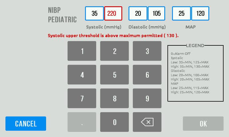
72 67

73 NIBP Settings The NIBP tab in the Settings menu allows users to select the NIBP reading method, disable/enable NIBP modes and displayed on the Main Screen, and set the default interval time between Interval NIBP readings. Use the Reading Method dropdown menu to select between linear and step deflation. See Blood Pressure Algorithms for full descriptions of linear and step deflation. If the Step Deflation method is selected, the initial inflation values for Adult and Pediatric mode may be edited. The NIBP tab in the Settings menu also allows the user to enable or disable Interval, Continuous, and Averaging modes using the slider. Interval mode takes an NIBP reading after each user selected standard interval until the user elects to finish the monitoring session. o Use the Default Interval dropdown menu to select a default interval length for the Interval mode. Continuous mode takes multiple BP measurements over a maximum time of 5 minutes. Averaging mode takes a series of five readings, disregards the first reading, and averages the next four readings to report an average BP reading. Press Apply on the NIBP tab to save all changes. 68

74 SpO 2 Settings The SpO2 tab in the Settings menu allows the user to disable or enable the features associated with each pulse oximeter. IQvitals Zone will automatically detect if a Masimo or Nellcor sensor is attached to the IQvitals Zone device. The Device Installed box displays the pulse oximeter attached to the IQvitals Zone device. Use the slider bars to enable or disable the following SpO 2 features : o PLETH Bars to display the 10-segment pulse amplitude indicator on the Main Screen. o PI Value to display the perfusion index percentage on the Main Screen. o Plethysmograph to display the graph on the Main Screen. When this feature is enabled, the Pulse Rate moves to the third row of the vital signs main screen to allocate space for the additional features. Similarly for Nellcor based unit, use the slider bars to enable or disable the following SpO2 features : o BLIP Bars to display the 10-segment pulse amplitude indicator on the Main Screen. o Plethysmograph to display the graph on the Main Screen. When this feature is enabled, the Pulse Rate moves to the third row of the vital signs main screen to allocate space for the additional features. Press Apply on the SpO 2 tab to save all changes. Below is the Main screen when all MASIMO options enabled: 69
75 Temperature Settings The Temp tab in the Settings menu displays the connection Status of the EXERGEN Temporal probe. Also, while in the Temperature Settings screen the User may change the temperature units Use the Units dropdown menu to select the unit of measurement (Fahrenheit or Celsius). Press Apply on the Temp tab to save all changes. Weight and Height Settings The WT/HT tab in the Settings menu allows users to enable or disable the following features: Weight Height BMI Digital scale (625 Table) If either the weight or height is disabled, the BMI will automatically become disabled. The user can change the units of measurement for weight and height using the Units dropdown menus. 70


76 More... The More tab in the Settings menu allows users to access the following: UPDATE VERSIONS Information FACTORY DEFAULT SETTINGS CLEAR MEMORY SERVICE MODE 1. On the main screen, confirm that the NIBP mode is set to Spot. 2. Select Settings Mode 3. Press the More tab Use the numeric key pad to enter the Service Mode password 1590, then press OK. The More screen is displayed. 71
77 Performing Check Calibration The Start button in the Service mode will be disabled during Blood pressure measurement or while the system is in Monitoring mode. This function should only be performed by qualified service personnel. For additional information contact Midmark Technical Service Department. 1. Select Service mode. Connect a calibrated NIBP simulator, aneroid, mercury column or pressure transducer (with known accuracy) to the NIBP cuff with a T connector. The NIBP cuff shall be wrapped around a suitable mandrel. Connect the hose coming from the pump on the bulkhead connector to the remaining cuff connection. Connect the remaining T connection to the return on the NIBP bulkhead connection as shown in the following illustration. 2. Select at least one low, one midrange and one high value then Press Start. Enter a value between 50 and 260 mmhg. 3. Device will inflate to and maintain the value entered in the manometer test window. The Start button will change to a Stop button. Compare this value to the reading given on your measurement device. Record the three measured values. 4. Add the Vital signs monitor accuracy tolerance (+/- 3mmHg or 2% whichever is greater) to the measurement transducer s accuracy tolerance to determine if the Vital signs monitor is within calibration. Example: Vital signs accuracy tolerance +/- 3 mmhg or 2% Measurement device tolerance +/- 1 mmhg Total tolerance +/- 4 mmhg or 2% + 1mmHg Pressure #1 = 250 mmhg +/- 3mmHg plus +/-1 mmhg = 244 to 256 mmhg PASS if between these values Pressure #2 = 100 mmhg +/- 3 mmhg plus +/- 1mmHg = 96 to 104 mmhg PASS if between these values Pressure #3 = 50 mmhg +/- 3 mmhg plus +/- 1mmHg = 47 to 53 mmhg PASS if between these values 72
78 5. Press the Close button to return to the More tab. Performing Over Pressure Check 1. Connect a calibrated NIBP simulator, aneroid, mercury column or pressure transducer (with known accuracy) to the NIBP cuff with a T connector. The NIBP cuff shall be wrapped around a suitable mandrill. Assure that the T connection is attached to the measurement side of the bulkhead connector. If necessary, the measurement side can be determined by running the NIBP pump. The side producing a pressure is the pressure side. The no pressure side is the measurement side. Connect a squeeze bulb to the remaining cuff connection and the pressure side of the bulkhead connector on the bulkhead connector using a T connection. See figure below. 2. Touch the inflation (mmhg) entry window and enter 250 mmhg. Press the START button. Allow the device to attain 250 mmhg. Monitor the manometer device and squeeze the squeeze bulb slowly until the cuff pressure releases. Record the pressure on the manometer at the moment pressure releases. PASS if between 285 to 315 mmhg. 73
79 If more than one repetition of the overpressure test is performed, the Stand-by/power to the device must be turned off then back on between tests to reset the over pressure feature. 3. Press the Close button to return to the More tab. Cleaning of IQvitals Zone The following table provides instructions for cleaning the IQvitals Zone and certain accessories and supplies. The IQvitals Zone should be cleaned monthly or as warranted. Before cleaning, refer to the cautions listed below. Part IQvitals Zone Recommended Cleaning Method Materials Soft cloths Protective gloves and eyewear Cleaning Agents Only the following cleaning agents are approved for use on the IQvitals Zone device: Enzymatic detergent, such as ENZOL (US) or CIDEZYME (outside the US) Distilled water Disinfectant solution, such as CIDEX OPA, or a 10% solution of house bleach (<5.25% sodium hypochlorite) in distilled water PDI Super Sani-Cloth Metrex CaviWipes Clorox Healthcare Bleach Germicidal Wipes, and Clorox Healthcare Hydrogen Peroxide Cleaner Disinfectant Procedure 1. Disconnect the unit from the wall outlet. 2. Put on gloves and protective eyewear. 3. Prepare the enzymatic detergent or disinfectant solution according to the manufacturer s instructions and in separate containers. 4. Apply disinfectant solution on affected area using a soft cloth and following the disinfectant manufacturer s instructions for use. 5. Wipe away excess solution 6. Clean product again with cloth dampened in distilled water. 7. Repeat as necessary 8. Allow to completely dry before use. SpO 2 Sensor Reusable BP Cuffs and Hose Materials 70% isopropyl alcohol pad Procedure 1. Remove sensor from patient and disconnect sensor cable from the device. 2. Wipe off with alcohol pad. Allow sensor to dry before placing it on a patient. For normal cleaning: mild detergents or a diluted bleach solution (1-2%), wipe cuff with the solution, rinse with water, and dry. For disinfecting: use a disinfecting solution such as Enzol, Cidezyme, Cidex, Sporicidin, Isopropyl Alcohol 70%, or Ethanol (70%), wipe or spray the cuff and allow to stand for approximately one minute. Rinse well with water and dry. 74
80 If the cuff is submerged in the disinfecting solution, the fittings should be capped to prevent liquid from getting inside the cuff. Always disconnect the IQvitals Zone from AC power before cleaning. Electronic devices can be damaged by exposure to liquids. Do not use or store the IQvitals Zone near any type of liquids. Do not use harsh chemicals for cleaning, especially disinfectants that contain phenol, as they can cause plastics to crack, soften, and spot. Do not steam-autoclave, gas-sterilize, or irradiate the unit; subject the unit to intense vacuum; or immerse the unit in water or cleaning solution. Keep cleaning liquids out of the unit and connectors. If any liquid gets inside the unit, allow it to dry in warm air for two hours, and then check to make sure all monitoring functions are working properly. Take particular care when cleaning the blood pressure cuff, blood pressure hose, and blood pressure connector on the IQvitals Zone to prevent fluid from entering the connectors. Fluid in the blood pressure airway may affect blood pressure determination accuracy and damage the monitor. Accessories and supplies that fall on the floor should be inspected for contamination and proper functionality. In case of contamination, follow the cleaning procedure detailed above. The user accepts responsibility for any deviations from the recommended method of cleaning and disinfection. 75
81 Maintenance and Battery Replacement Maintenance The following table shows the recommended maintenance procedures for the IQvitals Zone device and its accessories and supplies. IQvitals Zone requires periodic calibration checks. It is a good idea to check that the device is in good working order, as described in the table. Calibration checks should be done every 12 months and can be performed by qualified service personnel IQvitals Zone Function Mechanical Integrity Touch Screen Procedure Check for cracks, abrasive edges, and other signs of damage. Verify that screen is responsive to touch. On/Off LED Verify that the green On/Off LED is illuminated on the front of the IQvitals Zone when the unit is on. Speaker SpO 2 NIBP Temperature Alarms Power-cycle the IQvitals Zone and verify that the power-up speaker test tones are generated. Apply the pulse oximeter probe to your finger. Verify that the reported pulse rate matches your pulse rate as measured on your wrist and that the SpO 2 value seems reasonable (above 95% for a healthy non-smoker). Apply an appropriately sized blood pressure cuff to your arm. Measure your blood pressure and verify that the reported blood pressure is reasonably close to your typical blood pressure. None (self-checking). Testing of the alarm system is part of the IQvitals Zone device start process. To test the alarm system, restart the device (See Power/Stand by steps at Page 22) If the alarms do not trigger at start up please contact Midmark Technical Service at for service information. If one of the checks results in a functional failure, please contact Midmark Technical Service at , option 2. If an IQvitals Zone needs to be returned for repair or calibration, a return authorization number must first be obtained from Technical Service. 76
82 Battery Replacement This device uses a lithium ion battery designed specifically for this device and is not field replaceable. Contact Midmark Technical Service to arrange battery replacement service. - Battery Risk of fire and burns. Do not open, crush, puncture, incinerate, or short circuit external contacts Do not disassemble or alter battery pack. Do not expose to heat in excess of 122 F (50 C). The battery is a lithium ion battery and must be recycled or disposed of properly according to national or local regulations. 77
83 Support and Warranty Information For help diagnosing problems by phone with this product, contact Midmark Technical Service at (800) , option 2, or (844) , option 2. Contact Midmark Technical Service via Self-help knowledge base and live chat can be accessed at kb.midmark.com. Warranty Midmark warrants IQvitals Zone to be free from manufacturing and material defects for two (2) years from the original date of purchase. Warranty periods for accessories and supplies shipped at the time of original purchase are: one (1) year for blood pressure cuffs and SpO2 sensor; 90 days for other accessories and supplies. Any misuse or abuse of a Midmark product or accessory voids all applicable warranties. Please refer to midmark.com for the full and current Warranty Terms and Conditions. Return Materials Authorization To return any product for repair, a Return Materials Authorization (RMA) number must be obtained from Midmark Technical Service. This RMA number should be referenced on the package(s) containing the items to be returned and in any correspondence regarding the return. Shipping Before shipping any unit to Midmark, be certain that a RMA number has been issued and that all guidelines regarding this authorization are followed. We highly recommend that you follow all guidelines for the shipment of medical products set forth by the shipping company you choose to use. If a question should arise regarding the appropriate method of shipment, please feel free to ask when calling for your RMA number. It is ultimately the responsibility of the customer when shipping a product to ensure that all packages and their contents get to Midmark safely. Midmark will not assume responsibility for damage due to improper packaging, shipment or product use. Such actions will void all applicable warranties. Midmark Corporation 690 Knox Street, Suite 100 Torrance, California Phone: (310) USA: (800) , option 2 Fax:
84 Disposal The disposal of accessories and supplies such as blood pressure cuffs, temperature probes, and SpO2 sensors should be carried out according to the manufacturer s recommendations. The IQvitals Zone should be properly disposed of as well. The IQvitals Zone contains a lithium ion battery and electronic circuit boards that should not be incinerated, crushed, disassembled or exposed to extreme heat. See Product Overview and General Information at the start of this user guide for further precautions. 79
85 Accessories and Supplies The following table shows the accessories and supplies approved by Midmark for use with IQvitals Zone. Use only approved accessories and supplies with the IQvitals Zone. Substitution of a component different from those suggested could result in measurement error. Item Part Number AC Power Supply Kit (Power Supply & Cord) USB Cable Exergen Temporal ThermosSanner Exergen Disposable Caps Covers Box of Exergen Disposable Caps Covers Box of 1, Cable, Device Temperature Module Masimo Adult Reusable SpO2 Sensor (LNCS-DCI) Masimo SpO2 Patient Cable 4 (RCDOC-4) Nellcor Adult Reusable SpO2 Sensor2 (DS-100A) Nellcor SpO2 Patient Cable Nellcor Small Finger SpO2 Clip (DS-YSPD) Nellcor Sp02 Y-Sensor (DS-YS) Fairbanks Scale Dual Tube Blood Pressure Hose Reusable Blood Pressure Cuff, Child, 1 each (13-20 cm) Reusable Blood Pressure Cuff, Small Adult, 1 each (18-26 cm) Reusable Blood Pressure Cuff, Adult, 1 each (26-35 cm) Reusable Blood Pressure Cuff, Adult Long, 1 each (29-38 cm) Reusable Blood Pressure Cuff, Large Adult, 1 each (32-42 cm) Reusable Blood Pressure Cuff, Large Adult Long, 1 each (35-44 cm) Reusable Blood Pressure Cuff, Thigh, 1 each (42-50 cm) Single Use Blood Pressure Cuff, Child, pack of 5 (13-20 cm) Single Use Blood Pressure Cuff, Small Adult, pack of 5 (18-26 cm) Single Use Blood Pressure Cuff, Adult, pack of 5 (26-35 cm) Single Use Blood Pressure Cuff, Adult Long, pack of 5 (29-38 cm) Single Use Blood Pressure Cuff, Large Adult, pack of 5 (32-42 cm) Single Use Blood Pressure Cuff, Large Adult Long, pack of 5 (35-44 cm) Single Use Blood Pressure Cuff, Thigh, pack of 5 (42-50 cm) IQvitals Zone Mobile Cart IQvitals Zone Wall Mount Articulating Arm " Laptop Tray for IQvitals Zone " Tablet Tray for IQvitals Zone Dual, Cart Mounted Storage Bin Kit Wall Mounted Storage Bin Kit
86 Installation Location Position the IQvitals Zone device in a way that the user can disconnect the device from the power supply if necessary. Do not block the device in a way where it cannot be disconnected from the power supply. Mounting Options Wall Mount Articulating Arm and Mobile Cart See the IQvitals Zone Set-up Guide # that is packaged with the device set-up kit. 81
87 Electromagnetic Compatibility (EMC) Information Medical electrical equipment requires special precautions regarding electromagnetic compatibility (EMC). Portable and mobile radio frequency (RF) communications equipment can affect devices like the IQvitals Zone As such, the IQvitals Zone should not be used adjacent to other equipment. If the IQvitals Zone is used adjacent to such equipment, observe the IQvitals Zone unit to make sure it is operating properly after installation. The use of accessories and supplies other than those recommended by Midmark may result in increased EMC emissions or decreased EMC immunity of IQvitals Zone. This device meets the requirements of IEC Please refer to this standard regarding safety requirements for this device. Guidance and Manufacturer s Declaration: Electromagnetic Emissions The IQvitals Zone is intended for use in the electromagnetic environment specified below. The user of the IQvitals Zone should assure that it is used in such an environment. Emissions test Compliance Electromagnetic environment/guidance RF emissions CISPR 11 Group 1 RF emissions CISPR 11 Harmonic emissions IEC Voltage fluctuations flicker emission IEC Class A Class A Complies The IQvitals Zone uses RF energy only for its internal function. Therefore, its RF emissions are very low and are not likely to cause any interference in nearby electronic equipment. The IQvitals Zone is suitable for use in all establishments, including domestic establishments and those directly connected to the public low-voltage power supply network that supplies buildings. 82
88 Guidance and Manufacturer s Declaration: Electromagnetic Immunity The IQvitals Zone is intended for use in the electromagnetic environment specified below. The user of the IQvitals Zone should assure that it is used in such an environment. Immunity test Electrostatic discharge (ESD) IEC Electrical fast transient/ burst IEC Surge IEC Voltage dips, short interruptions and voltage variations on power supply input lines IEC Power frequency (50/60 Hz) magnetic field IEC IEC test level ±6 kv contact ±4 kv air ±2 kv for power supply lines ±1 kv for input/ output lines ±1 kv differential Mode ±2 kv common mode <5% UT (>95% dip in UT) for 0.5 cycle 40% UT (60% dip in UT for 5 cycles 70% UT (30% dip in UT) for 25 cycles <5% UT (>95% dip in U T ) for 5 s 3 A/m 3 A/m Compliance level ±6 kv contact ±4 kv air ±2 kv for power supply lines ±1 kv for input/ output lines ±1 kv differential Mode ±2 kv common mode <5% UT (>95% dip in UT) for 0.5 cycle 40% UT (60% dip in UT) for 5 cycles 70% UT (30% dip in UT) for 25 cycles <5% UT (>95% dip in U T ) for 5 s Electromagnetic environment/ guidance Floors should be wood, concrete, or ceramic tile. If floors are covered with synthetic material, the relative humidity should be at least 30%. Mains power quality should be that of a typical commercial or hospital environment. Mains power quality should be that of a typical commercial or hospital environment. Mains power quality should be that of a typical commercial or hospital environment. If the user of the IQvitals Zone requires continued operation during power mains interruptions, it is recommended that the IQvitals Zone be powered from an uninterruptible power supply or a fully charged battery. Power frequency magnetic fields should be at levels characteristic of a typical location in a typical commercial or hospital environment. 83
89 Guidance and Manufacturer s Declaration: Electromagnetic Immunity The IQvitals Zone is intended for use in the electromagnetic environment specified below. The user of the IQvitals Zone should assure that it is used in such an environment. Immunity test IEC test level Complianc e level Electromagnetic environment/guidance Portable and mobile RF communications equipment should be used no closer to any part of the IQvitals Zone, including cables, than the recommended separation distance calculated from the equation applicable to the frequency of the transmitter. Recommended separation distance is Conducted RF IEC Radiated RF IEC Vrms 150 khz to 80 MHz 3 V/m 80 MHz to 2.5 GHz 3 Vrms 3 V/m where P is the maximum output power rating of the transmitter in watts (W) according to the transmitter manufacturer, and d is the recommended separation distance in meters (m). Field strengths from fixed RF transmitters, as determined by an electromagnetic site survey a, should be less than the compliance level in each frequency range b. Interference may occur in the vicinity of equipment marked with the following symbol: a) Field strengths from fixed transmitters, such as base stations for radio cellular/cordless) telephones and land mobile radios, amateur radio, AM and FM radio broadcasts, and TV broadcast, cannot be predicted theoretically with accuracy. To assess the electromagnetic environment due to fixed RF transmitters, an electromagnetic site survey should be considered. If the measured field strength in the location in which the IQvitals Zone is used exceeds the applicable RF compliance level above, the IQvitals Zone should be observed to verify normal operation. If abnormal performance is observed, additional measures may be necessary, such as re-orienting or relocating the IQvitals Zone. b) Over the frequency range 150 khz to 80 MHz, field strengths should be less than 3 V/m. 84
90 Recommended Separation Distances Between Portable and Mobile RF Communications Equipment and the IQvitals Zone The IQvitals Zone is intended for use in an electromagnetic environment in which radiated RF disturbances are controlled. The user of the IQvitals Zone can help prevent electromagnetic interference by maintaining a minimum distance between portable and mobile RF communications equipment (transmitters) and the IQvitals Zone as recommended below, according to the maximum output power of the communications equipment. Rated maximum output power of transmitter (W) Separation distance according to frequency of transmitter (m) 150 khz to 80 MHz 80 MHz to 800 MHz 800 MHz to 2.5 GHz For transmitters rated at a maximum output power not listed above, the recommended separation distance d in meters (m) can be estimated using the equation applicable to the frequency of the transmitter, where P is the maximum output power rating of the transmitter in watts (W) according to the transmitter manufacturer. At 80 MHz and 800 MHz, the separation distance for the higher frequency range applies. These guidelines may not apply in all situations. Electromagnetic propagation is affected by absorption and reflection from structures, objects, and people 85
91 Appendix A Alarm States and Priority Levels The following list provides the alarm capabilities of each IQvitals Zone device model. Device Model Number Technical Alarms X X X Physiological Alarms X X X X X X A technical alarm will occur if a device function needs to be addressed. Devices providing technical alarms are shipped with these alarms ENABLED. A physiological alarm will occur when a vital sign measurement being taken falls outside a preset threshold. The devices that provide physiological alarms are shipped with these alarms ENABLED. Each vital sign parameter will have factory determined thresholds. The user may change the parameter threshold settings in the Settings menu for each parameter. Physiological alarms are considered global meaning that the alarm feature will apply to all vital sign parameters the device is capable of measuring. The user cannot select which individual vital sign parameter will have an alarm and which will not. Factory set default thresholds can be restored through the Alarm Settings. The IQvitals Zone device does not keep a perpetual log of alarm occurrences. Visual and Audible Alarm Notification The IQvitals Zone provides three priorities: High, Medium and Low. Each alarm provides both visual and audible notifications. It is important to remain in close proximity to the device to maintain clear visual contact with the monitor and to be able to hear the audible alarms should they occur. 86
92 Alarm State Color LED Light Steady or Flash Audible Alarm Tone Audible Alarm Repeat High Red Steady 3 beeps followed by 2 beeps, Every 2.5 seconds (runs 2 consecutive times) Medium Amber Steady 3 beeps Every 7.5 seconds Low Amber Steady 2 beeps Every 20 seconds Text will be provided on the device screen informing the user which alarm requires attention. Both physiological and technical alarms will display in the Alarms box (lower right) on the Main Testing screen. All alarm states will continue to display or sound until the applicable issue is corrected. The Alarm Reset button in the Alarms box allows the user to reset or pause the audible portion of the alarm and disable the LED light bar, however, the alarm message will continue to display on the Main Screen until the issue is corrected. 87
93 Alarm Priority Should more than one parameter require attention and activate an alarm, the highest urgency alarm will display first. For example: should a Medium alarm activate then a High alarm activate, the HIGH priority parameter that triggered the alarm will be highlighted on the screen and the light on the front of the device will display red for the HIGH priority alarm. Once the High priority alarm is corrected the device will then display the next alarm to be addressed. Should two or more MEDIUM alarms occur at the same time, the device will display which alarm occurred first. Once the first Medium alarm is corrected the device will then display the next Medium alarm to be addressed. Same applies should two or more LOW alarms occur at the same time. Alarm buttons for the IQvitals Zone and a brief description of each. Button Description Alarm. This button will appear this way to indicate there are no active alarms. Alarm Reset. The Alarm button (above) will be highlighted in amber in the event of an active alarm or multiple active alarms. The Alarm button will return to this state if the Alarm Reset button (above) is pressed indicating an alarm has been reset or paused but not yet corrected. The alarm description will remain on the Main Screen just above this button until the issue is corrected. The IQvitals Zone does not store activated alarms by patient. Alarm Reset An audible alarm can be reset or paused by the user by pressing the Alarm Reset button on the Main Screen. If an audible alarm is paused, the light bar will be extinguished and the audible tones will stop, however, the text notification on the Main Screen within the Alarms box will continue to display the be addressed or corrected. Should multiple alarms require attention, the device will provide audible and visual indicators for the highest priority alarm. If the Alarm Reset button is pressed, the first (or highest priority) alarm will silence. The device will then provide audible and visual indicators for the next alarm. If the Alarm Reset button is pressed for all remaining active alarms, the device light bar will then indicate the color associated with the first (or highest priority) alarm that needs attention. Although the audible tone and the light bar is extinguished, the trained clinician must address and correct the indicated issues. The only way an alarm can truly be stopped is for the associated issue to be corrected. Once corrected, all audible and visual indicators will cease. 88
94 Physiological and Technical Alarms The following list explains the physiological and technical alarm messages and their priority level. Physiological Alarms Messages Alarm messages Displayed Message Priority Alarm limit exceeded. NIBP systolic HIGH NIBP Systolic HIGH High Alarm limit exceeded. NIBP systolic LOW. NIBP Systolic LOW High Alarm limit exceeded. NIBP diastolic HIGH. NIBP Diastolic HIGH High Alarm limit exceeded. NIBP diastolic LOW. NIBP Diastolic LOW High Alarm limit exceeded. NIBP MAP HIGH. NIBP MAP HIGH High Alarm limit exceeded. NIBP MAP LOW. NIBP MAP LOW High Alarm limit exceeded. SpO2 HIGH. SpO2 HIGH High Alarm limit exceeded. SpO2 LOW. SpO2 LOW High Alarm limit exceeded. Pulse rate HIGH. Pulse Rate High Medium Alarm limit exceeded. Pulse rate LOW. Pulse Rate LOW Medium Alarm limit exceeded. PI High PI HIGH Medium * Alarm limit exceeded. PI Low PI LOW Medium * Alarm limit exceeded. Temperature HIGH. Temperature HIGH Low Alarm limit exceeded. Temperature LOW. Temperature LOW Low * Only MASIMO 89
95 Technical Alarms Messages Alarm messages Displayed Message Priority SPO2 (Masimo) No cable Connected No cable Connected Low Cable Life Expired Cable Life Expired Low Incompatible Cable Incompatible Cable Low Unrecognized Cable Unrecognized Cable Low Defective Cable Defective Cable Low Cable Life Near Expiration Cable Life Near Expiration Low No Sensor Connected No Sensor Connected Low Sensor Life Expired Sensor Life Expired Low Incompatible Sensor Incompatible Sensor Low Unrecognized Sensor Unrecognized Sensor Low Defective Sensor Defective Sensor Low Check Cable and Sensor Fault Check Cable and Sensor Fault Low Sensor Life Near Expiration Sensor Life Near Expiration Low No Adhesive Sensor No Adhesive Sensor Low Adhesive Sensor Life Expired Adhesive Sensor Life Expired Low Incompatible Adhesive Sensor Incompatible Adhesive Sensor Low Unrecognized Adhesive Sensor Unrecognized Adhesive Sensor Low Defective Adhesive Sensor Defective Adhesive Sensor Low Adhesive Life Near Expiration Adhesive Life Near Expiration Low Sensor Initializing Sensor Initializing Low Sensor Off patient Sensor Off patient Low Pulse Search Spinning Wheel Low Interference Detected Interference Detected Low Low Perfusion Index See Physiological alarms Low Check Sensor Connection Check Sensor Connection Low SPO2 (NELLCOR) Sensor Detached from Patient Sensor Off patient Low Sensor Disconnect No Sensor Connected Low Interference Detected Interference Detected Low NIBP NIBP air leak; check cuff and tubing connections. NIBP Air Leak Low Unable to determine NIBP; check connections and tubing for kinks. Unable to determine NIBP Low Inflation too quick; checking NIBP cuff and tubing connections Inflation too quick Low Pressure out of the range (Systolic , Diastolic ) NIBP Error Low Battery Low battery at 40% Low Battery Low Low battery at 20% Low Battery Low Low battery at 10% Critical Battery High 90
96 Alarm messages Displayed Message Priority Battery is absent or faulty. Call for service. Battery is absent or faulty Low Weight scale Fairbanks Weight scale not functional Fairbanks scale not functional Low 625 Table Weight scale not functional. 625 Table scale not functional. Low System Communication (when each of the items below is part of the system) Loss of pairing with wireless devices No Pairing icon is displayed. Loss of wireless pairing Icon Communication with the Fairbanks scale module Failed Loss of Fairbanks scale Comm. Low Communication with the 625 Table Scale module Failed Loss of 625 Table Comm. Low Communication with the wireless Board failed Loss of wireless Comm. Low Communication with SPO2 module Failed Loss of SpO2 Comm. High Communication with NIBP Loss of NIBP Comm. High Communication with Display Board Loss of LCD Comm. High System Set date and time. (warning) Set date and time Low Maximum number of patient records saved. Oldest record will be overwritten. Max number of patient records Unable to access patient information. Cannot access patient info High Unable to load configuration; using factory defaults. Unable to load configuration High Medium 91

97 Alarm Threshold Limits The following list provides the threshold limits for each vital sign parameter and is separated for Adult and Pediatric patient populations. Adult - Vital sign parameter threshold limits 92


98 Pediatric - Vital sign parameter threshold limits Alarm Signal Sound Pressure Range 93
 / DCIP (Pediatric) Sensor vs. CO-oximeter : Arms = Accuracy root means square.")
99 Appendix B Pulse Oximeter Measured SpO2 Accuracy Specification (Graphical Plot and Table) Masimo Table information for the Blend-Altman plots show Arms values measured with Masimo SET Oximetry Technology in a clinical study. SpO2 Accuracy for Masimo DCI (Adult) / DCIP (Pediatric) Sensor vs. CO-oximeter : Arms = Accuracy root means square. A rms was calculated from the formula 94
100 Nellcor Table information for the Blend-Altman plots show Arms values measured with Nellcor Oximetry Technology in a clinical study. SpO2 Accuracy for Nellcor DS100A Sensor (Adult) vs. CO-oximeter MEASURED Arms VALUES Range Arms 70-80% 3.24% 80-90% 2.13% % 1.61% SpO2 Accuracy for Nellcor NELL1-DY-S Sensor (Pediatric) vs. CO-oximeter MEASURED Arms VALUES Range Arms 70-80% 3.08% 80-90% 1.90% % 2.68% % 2.62% 95
101 s: 96

102 Midmark Corporation 690 Knox Street, Suite 100 Torrance, CA USA midmark.com
Connex Integrated Wall System 2.2 Software Version
 Connex Integrated Wall System 2.2 Software Version Clinical Inservice Presentation MC12931 1 Table of Contents Device Overview & Intended Use Power ON Power OFF Home Screen Navigation Spot Profile Intervals
Vital Signs Monitor 300 Series
 Vital Signs Monitor 300 Series Directions for Use Software version 1.2X ii Welch Allyn Vital Signs Monitor 300 Series Copyright 2005 Welch Allyn. All rights are reserved. No one is permitted to reproduce
Vital Signs Monitor 300 Series
 Vital Signs Monitor 300 Series Directions for Use Software version 1.2X ii Welch Allyn Vital Signs Monitor 300 Series 2009 Welch Allyn. All rights are reserved. No one is permitted to reproduce or duplicate,
Vital Signs Monitor 300 Series
 Vital Signs Monitor 300 Series Directions for use Software version 1.2X ii Welch Allyn Vital Signs Monitor 300 Series 2014 Welch Allyn. All rights are reserved. To support the intended use of the product
Track the truth. Give no false assurance. Do no harm. Nellcor SpO 2. Module for use with Philips IntelliVue * Patient Monitors
 Track the truth Give no false assurance Do no harm Nellcor Module for use with Philips IntelliVue * Patient Monitors Nellcor Module Features Designed to be used in a range of critical care environments
User Guide. Cardell Insight Veterinary Monitor. For Models: 8014 Blood Pressure Blood Pressure, Pulse Oximetry
 Cardell Insight Veterinary Monitor For Models: 8014 Blood Pressure 8015 Blood Pressure, Pulse Oximetry User Guide 003-2981-00 Rev. B (2/21/17) Software Version 1.2V Product Information Dealer: Date of
CLEO VERSATILITY IN VITAL SIGNS
 CLEO VERSATILITY IN VITAL SIGNS CLEO PORTABLE weighs less than 3 lbs TOUCHSCREEN easy and intuitive to use MOBILE backup battery powered The Cleo is a new and intuitive approach to patient vital signs
OMNI Express VS VERSATILITY IN VITAL SIGNS
 OMNI Express VS VERSATILITY IN VITAL SIGNS OMNI Express VS TOUCHSCREEN easy and intuitive to use PORTABLE weighs less than 6lbs MOBILE backup battery powered The Omni Express VS is a new intuitive approach
Operator s Manual. Avant Pulse Oximeter and Noninvasive Blood Pressure (NIBP) Monitor English
 Monitor English") Operator s Manual Avant 2120 Pulse Oximeter and Noninvasive Blood Pressure (NIBP) Monitor 0123 English CAUTION: Federal law (USA) restricts this device to sale by or on the order of a licensed practitioner.
Operator s Manual Avant 2120 Pulse Oximeter and Noninvasive Blood Pressure (NIBP) Monitor 0123 English CAUTION: Federal law (USA) restricts this device to sale by or on the order of a licensed practitioner.
OPERATOR S MANUAL. For YM1000 Vital Signs Monitor. EU Representative TECNOMED 2000 S.L. Valencia, Madrid Spain
 OPERATOR S MANUAL For YM1000 Vital Signs Monitor EU Representative TECNOMED 2000 S.L. Valencia, 25 28012 Madrid Spain Manufacturer Mediana Co., Ltd. Wonju Medical Industry Park, 1650 1 Donghwa ri, Munmak
5/ 5i/ 5c/ 7/ 7i/ 7c/ 5 elite/ 5i elite/ 5c elite/ 7 elite/ 7i elite/ 7c elite
 Summary The élance 5 / 5i / 5c / 7 / 7i / 7c /5 elite/ 5i elite / 5c elite / 7 elite / 7i elite /7c elite are integrated vital signs monitors with widescreen resistive touchscreen display. The monitors
SureSigns VS4. Vital Signs Monitor Technical Data Sheet
 SureSigns VS4 Vital Signs Monitor Technical Data Sheet The SureSigns VS4 is a vital signs monitor that measures blood pressure, pulse rate, oxygen saturation (SpO 2 ), and temperature. The VS4 monitor
DINAMAP ProCare Monitor. Operation Manual
 DINAMAP ProCare Monitor Operation Manual Contents Introduction About the DINAMAP ProCare Monitor...7 Indications...7 Contraindications...7 Warnings... 8 Cautions...9 Product Compliance...10 Symbols...11
Vital Signs Monitor. 300 Series. Directions for Use. Software Version 1.0X
 Vital Signs Monitor 300 Series Directions for Use Software Version 1.0X Copyright 2003, Welch Allyn Protocol, Inc. Welch Allyn is a registered trademark of Welch Allyn, Inc. Protocol is a trademark of
Nellcor with OxiMax Technology Product Ordering Guide A Full Line of Oximetry Sensors and Monitors
 Nellcor with OxiMax Technology Product Ordering Guide A Full Line of Oximetry Sensors and Monitors Specialty sensors Forehead Sensor For patients with low perfusion; suitable for long-term monitoring Forehead
Welch Allyn Connex Devices
 Welch Allyn Connex Devices Directions for use Software version 2.3X 2017 Welch Allyn. All rights are reserved. To support the intended use of the product described in this publication, the purchaser of
Product Specifications
 1.Safety Specifications 1.1Product Classification Class Type of protection against electric shock Specification Class I, with internal power supply Degree of protection against electric shock Anti-defibrillation:
Operator s Manual. Avant Pulse Oximeter and NIBP Monitor. English
 Operator s Manual Avant 2120 Avant 2120 Pulse Oximeter and NIBP Monitor 0123 English CAUTION: Federal law (USA) restricts this device to sale by or on the order of a licensed practitioner. Consult Instructions
Infinity M300 Patient Worn Monitoring
 Infinity M300 Patient Worn Monitoring Managing the care of ambulatory patients is challenging because you need to balance mobility with patient safety. The innovative Infinity M300 patientworn monitor
OMNI TOUCH SCREEN PATIENT MONITOR
 OMNI TOUCH SCREEN PATIENT MONITOR OMNI Intuitive Designed for a fast paced work environment, the Infinium Omni patient monitor offers an extremely simple and adaptable user interface. Patient information
Welch Allyn Vital Signs Monitor 6000 Series. Directions for use
 Welch Allyn Vital Signs Monitor 6000 Series Directions for use 2010 Welch Allyn. All rights are reserved. To support the intended use of the product described in this publication, the purchaser of the
Operator s Manual. Avant Pulse Oximeter and NIBP Monitor. English
 Operator s Manual Avant 2120 Avant 2120 Pulse Oximeter and NIBP Monitor 0123 English 1 CAUTION! CAUTION! Federal law (USA) restricts this device to sale by or on the order of a physician. Read this entire
qube mini Overview
 D a t a S h e e t qube mini Overview The 91389 qube mini is a compact, robust, and light-weight patient monitor with extensive clinical usability. Key features of the qube mini monitor include: Eye-level
DPM Summary of Features and Benefits
 Summary of Features and Benefits PAT I E N T M O N I TO R 12.1" TFT display, configurable up to 8 waveforms, enables maximum data analysis of your most critical parameters Standard features include 3/5-lead
ANGELUS (Ver 2.03) Patient Monitoring System
 Patient Monitoring System") ANGELUS (Ver 2.03) Patient Monitoring System CONTENT Contents of Manual 1 Meaning of Symbols used in this manual 2 Section 1. GENERAL 3 1.1 Introduction 4 1.2 Composition of unit 8 1.3 Panel Description
ANGELUS (Ver 2.03) Patient Monitoring System CONTENT Contents of Manual 1 Meaning of Symbols used in this manual 2 Section 1. GENERAL 3 1.1 Introduction 4 1.2 Composition of unit 8 1.3 Panel Description
SpotOn Temperature Monitoring System. SpotOn. Temperature Monitoring System. Model 370 Installation and Service Manual
 3 SpotOn Temperature Monitoring System Model 370 Installation and Service Manual Please forward to the Biomedical Engineering Department 3M SpotOn Temperature Monitoring System Revision History Revision
Model 900. Pulse Oximeter User s Manual
 Model 900 Pulse Oximeter User s Manual MEDIAID INC. 17517 Fabrica Way Suite H, Cerritos, CA 90703 USA Phone: 714-367-2848; Fax: 714-367-2852 Website: www.mediaidinc.com POX010-900 Contents Table of Contents
CASMED 740 Vital Signs Monitor
 CASMED 740 Vital Signs Monitor User s Manual 2 THE CASMED 740 VITAL SIGNS MONITOR FEATURES CASMED 740-1 Non-Invasive Blood Pressure and Pulse Rate. CASMED 740-2 Non-Invasive Blood Pressure, Pulse Rate
ARGUS VCM Vital Compact Monitor
 Vital Compact Monitor Art. No.: 2.540041 Rev. a *2.540041* Service Handbook Contents Figures Tables Notice This document contains proprietary information that is protected by copyright. All Rights Reserved.
Nellcor Bedside SpO 2 Patient Monitoring System, PM100N
 Nellcor Bedside SpO 2 Patient Monitoring System, PM100N In-Service Presentation Nellcor Bedside SpO 2 Patient Monitoring System is CE marked and commercially av ailable in European Union countries. Nellcor
DINAMAP PRO Series V2 Monitor. Operation Manual
 PRO Series 100-400V2 Operation Manual DINAMAP PRO Series 100-400V2 Monitor Operation Manual 1 DINAMAP PRO 400V2 Monitor 2 DINAMAP PRO Series 100-400V2 Monitor Operation Manual This manual is for DINAMAP
T1 BEDSIDE MONITOR GUIDELINE
 APPENDIX A T1 BEDSIDE MONITOR GUIDELINE 5.23 Software Version This document is a guideline only to be used as an aid to comprehensive Inservice training. NAME: HOSPITAL: DATE: VALIDATOR: A. OVERVIEW 1.
Vitalmax 4000 CL Product Specifications
 Page 1 of 5 Vitalmax 4000 CL 510 Garden Avenue North, Clearwater, FL 33755 Phone: (727) 442-8118 Fax: (727) 443-7257 A. Mechanical Description Size 10" H x 13" W x 8"D (25 cm x 33 cm x 20 cm) Weight 18
Operating manual Reusable Pulse Oximetry Sensors
 Operating manual Reusable Pulse Oximetry Sensors FingerClip, Earclip, Multisite Wrap, Multisite Y, SoftTip plus (autoclavable), SoftTip 006-07-GA_SpO2_sensors_reusable-1 1002237 DEU GBR DNK GRC ESP HUN
OPERATOR S MANUAL. Patient Monitor M20. EU representative TECNOMED 2000 S.L. Valencia, Madrid Spain
 OPERATOR S MANUAL Patient Monitor M20 EU representative TECNOMED 2000 S.L. Valencia, 25-28012 Madrid Spain Manufacturer Mediana Co., Ltd. Wonju Medical Industry Park, 1650-1 Donghwa-ri, Munmak-eup, Wonju-si,
GE Healthcare. Quick Guide. Dash 2500 Patient Monitor
 GE Healthcare Quick Guide Dash 2500 Patient Monitor Hardkeys Main Menu Hide menu and view entire waveform screen Display the large numeric vital signs Review or change alarm limits for all operating parameters
About this Manual. Statement. P/N: Release Date: August 2010 Copyright EDAN INSTRUMENTS, INC All rights reserved.
 About this Manual P/N: 01.54.110221-13 Release Date: August 2010 Copyright EDAN INSTRUMENTS, INC. 2008-2010. All rights reserved. Statement This manual will help you understand the operation and maintenance
Operator s Manual. Avant Digital Pulse Oximeter. English
 Operator s Manual Avant 9600 Avant 9600 Digital Pulse Oximeter 0123 English 1 Declaration of Conformity Manufacturer: Nonin Medical, Inc. Address: 2605 Fernbrook Lane North Plymouth, Minnesota 55447-4755
Welch Allyn Connex Devices. Directions for use
 Welch Allyn Connex Devices Directions for use 2014 Welch Allyn. All rights are reserved. To support the intended use of the product described in this publication, the purchaser of the product is permitted
MRI Patient Monitoring System (Model )
") MRI Patient Monitoring System (Model 865214) INSTRUCTIONS FOR USE Revision C English A Specifications Specifications PATIENT SAFETY GENERAL Conforms to UL STD 60601-1. Certified to CAN/CSA STD C22.2 No.
MRI Patient Monitoring System (Model 865214) INSTRUCTIONS FOR USE Revision C English A Specifications Specifications PATIENT SAFETY GENERAL Conforms to UL STD 60601-1. Certified to CAN/CSA STD C22.2 No.
Omni (K) PATIENT MONITOR
 PATIENT MONITOR") Omni (K) PATIENT MONITOR Omni (K) Intuitive Designed for a fast paced work environment, the Infinium Omni (K) patient monitor offers an extremely simple and adaptable user interface. Patient information
Omni (K) PATIENT MONITOR Omni (K) Intuitive Designed for a fast paced work environment, the Infinium Omni (K) patient monitor offers an extremely simple and adaptable user interface. Patient information
PULSE OXIMETER PACKAGE
 instrumentation and software for research PULSE OXIMETER PACKAGE CANL-425SV-A USER S MANUAL DOC-095 Rev. 1.6 Copyright 2012 All Rights Reserved Med Associates Inc. P.O. Box 319 St. Albans, Vermont 05478
TidalGuard HD. Handheld CO 2 / SpO 2 and CO 2 monitors. Operating Manual Rev. H (8/15)
") TidalGuard HD Handheld CO 2 / SpO 2 and CO 2 monitors Operating Manual 003-2275-00 Rev. H (8/15) Table of Contents Table of Contents Service Information... iv Preface... vi 1. Safety... 1-1 1.1 Safety
TidalGuard HD Handheld CO 2 / SpO 2 and CO 2 monitors Operating Manual 003-2275-00 Rev. H (8/15) Table of Contents Table of Contents Service Information... iv Preface... vi 1. Safety... 1-1 1.1 Safety
HUG.ai 1/24/06 9:33:34 AM HUG.ai 1/24/06 9:33:34 AM C M Y CM MY CY CMY K
 HUG.ai 1/24/06 9:33:34 AM C M Y CM MY CY CMY K This ISM device complies with Canadian ICES-001. Cet appareil ISM est conforme à la norme NMB-001 Canada. Nellcor Puritan Bennett Inc. is an affiliate of
Genesis DM Installation Readiness
 Genesis DM Installation Readiness Step by Step Readiness 1 2015 Honeywell International All Rights Reserved CP410.01 Overview Who should attend this presentation? Installers of Genesis DM monitors Initial
Operator s Manual. LifeSense LS1-9R. Vital Signs Monitor. Capnography/Pulse Oximeter
 Operator s Manual Vital Signs Monitor Capnography/Pulse Oximeter LifeSense LS1-9R CAUTION: Federal law (USA) restricts this device to sale by or on the order of a licensed practitioner. Consult Instructions
PM-9000 Express Portable Patient Monitor
 FEATURES 12.1" color TFT with maximum 8 waveforms Rich in ECG software OxyCRG software available 40 seconds full-disclosure waveforms review Drug dose calculation Bed to bed view Networking capacity Multi-Gas/O2
Digital Heat Block User Manual
 Digital Heat Block User Manual Quidel Digital Heat Block Page 1 of 10 General Information Quidel Contact Information Contact Quidel Technical Support from 8:00 a.m. to 5:00 p.m. EST Tel: 800.874.1517 (in
Getting Started. Genesis Touch System
 Getting Started Genesis Touch System Getting Started P4810EN.02 2012 Honeywell HomMed. All rights reserved. 1/27/12 Table of Contents Indications for Use...1 Contra-Indications...1 Purpose of this Document...1
Safe Operation Manual. Honeywell IQ Force Gas Detector
 Safe Operation Manual Honeywell IQ Force Gas Detector Honeywell Analytics 800-663-4164 403-248-9226 Fax 403-575-3708 03JUN2012 P/N 50105843-047 Version 01 http://www.honeywell.com HONEYWELL IQ Force PERSONAL
OPERATOR S MANUAL. NPB-4000/4000C Patient Monitor
 OPERATOR S MANUAL NPB-4000/4000C Patient Monitor Nellcor Puritan Bennett Inc. is an affiliate of Tyco Healthcare. Nellcor, Nellcor Puritan Bennett, Durasensor, C-LOCK, Oxisensor II, Dura-Y, and the Nellcor
901-M / 901-ML. Pulse Oximetry System. Technical Information and Service Manual
 901-M / 901-ML Pulse Oximetry System Technical Information and Service Manual CONTENTS 1. PRELIMINARY REMARK...... 4 2. FUNCTION DESCRIPTION......... 5 2.1. INTENDED USE...5 2.2. CONTRAINDICATION...5 2.3.
Welch Allyn Connex Devices
 Welch Allyn Connex Devices Directions for use Software version 2.4X 2018 Welch Allyn. All rights are reserved. To support the intended use of the product described in this publication, the purchaser of
CNAP MONITOR 500 HD QUICK GUIDE. This Quick Guide DOES NOT REPLACE the user manual!
 CNAP MONITOR 500 HD QUICK GUIDE This Quick Guide DOES NOT REPLACE the user manual! Version 07/2016 V1.5.5 EN 2 CONTENT SET UP MEASUREMENT NAVIGATION FAQs FUNCTIONS: FAST ACCESS Hemodynamic Parameters...5
Quick Touch Pendant User Guide
 Quick Touch Pendant User Guide 2018 RF Technologies, Inc. All specifications subject to change without notice. All Rights Reserved. No Part of this work may be reproduced or copied in any form or by any
VitalCare 506N3 Series Patient Monitor Operator s Manual
 VitalCare 506N3 Series Patient Monitor Operator s Manual Cat. No. 1445 Date 01/07 Part No. 39180B001 Revision 0 Copyright COPYRIGHT CRITICARE SYSTEMS, INC., 2005-2007 CRITICARE SYSTEMS, INC. (Criticare)
The Blood Pressure Monitor is digital upper arm monitors intended for use in measuring blood pressure and heartbeat rate with upper arm circumference
 The Blood Pressure Monitor is digital upper arm monitors intended for use in measuring blood pressure and heartbeat rate with upper arm circumference ranging from 22cm to 32 cm ( about 83/4-121/2 ).It
WARNINGS AND CAUTIONS WARNING. Federal law restricts this device to sale by or on the order of a physician or other licensed practitioner.
 WARNINGS AND CAUTIONS WARNING Federal law restricts this device to sale by or on the order of a physician or other licensed practitioner. WARNING The OXYSHUTTLE + 2 Pulse Oximeter should only be operated
1 Appendix - Product Specifications
 1 Appendix - Product Specifications WARNING The patient monitor may not meet its performance specification if stored or used outside the manufacturer s specified temperature and humidity range. 1.1 Safety
Model 7500 Model 7500
 Operator s Manual Model 7500 Model 7500 Digital Pulse Oximeter 0123 English 1 CAUTION: Federal law (USA) restricts this device to sale by or on the order of a licensed practitioner. Consult Instructions
signal extraction pulse oximeter OPERATOR S MANUAL
 signal extraction pulse oximeter OPERATOR S MANUAL Signal Extraction Pulse Oximeter OPERATOR S MANUAL The Radical-7 Operating Instructions provide the necessary information for proper of all models of
HBP Patient Monitor. Operator s Manual. EU representative OBELIS S.A Bd. Général Wahis, Brussels, Belgium.
 Patient Monitor HBP-2070 Operator s Manual EU representative OBELIS S.A Bd. Général Wahis, 53 1030 Brussels, Belgium Local distributor Manufacturer Mediana Co., Ltd. Wonju Medical Industry Park, 1650-1
Kinsa Smart Ear ThermometerTM Instructions For Use
 ENGLISH Kinsa Smart Ear ThermometerTM Instructions For Use Thank you for purchasing the Kinsa Smart Ear Thermometer, a professionally accurate instrument for fast and easy temperature taking in the ear.
(Place Logo from Lab here)
") Rad-5 & Rad-5v Signal Extraction Pulse Oximeter Service Manual (Place Logo from Lab- 1874 here) Rad-5 & Rad-5v Signal Extraction Pulse Oximeter Service Manual The Rad-5/5v Service Manual is intended to
Rad-5 & Rad-5v Signal Extraction Pulse Oximeter Service Manual (Place Logo from Lab- 1874 here) Rad-5 & Rad-5v Signal Extraction Pulse Oximeter Service Manual The Rad-5/5v Service Manual is intended to
Patient Monitoring System YM5500. Service Manual
 Patient Monitoring System YM5500 Service Manual SERVICE MANUAL For YM5500 Patient Monitor Mediana Co.,Ltd. 231-6 Nonhyun-Dong, Kangnam-Ku, Seoul, Korea Tel: (82) 2 542 3375 Fax: (82) 2 542 7447 YM5500
Atlas Monitor Outline Train the Trainer
 Atlas Monitor Outline Train the Trainer A. ATLAS Monitor 1. Atlas Monitor is not designed for use on children younger than 3 years old. 2. Weight: 9.5lbs to 13.2 lbs, depending on configuration 3. Variable
MODEL 3X Series User s Manual
 MODEL 3X Series User s Manual Pulse Oximeter with options for 24 hour Memory, Printer & USB / Infrared Ports MEDIAID INC. 17517 Fabrica Way Suite H Cerritos, CA 90703 USA (Tel) 714-367-2848 (Fax) 714-367-2852
Operator s Manual. Model 7500FO. Model 7500FO. Digital Pulse Oximeter. English
 Operator s Manual Model 7500FO Model 7500FO Digital Pulse Oximeter 0123 English 1 CAUTION: Federal law (USA) restricts this device to sale by or on the order of a licensed practitioner. Consult Instructions
HANDHELD PULSE OXIMETER
 Attendant HANDHELD PULSE OXIMETER Owner s Manual Please keep and refer to this Owner s Manual. Thank you for purchasing an Attendant Handheld Pulse Oximeter from Direct Supply Equipment & Furnishings.
Passport 12m and Passport 17m BEDSIDE MONITOR GUIDELINE 5.21 Software Version NAME: HOSPITAL: DATE: VALIDATOR: Performed
 Passport 12m and Passport 17m BEDSIDE MONITOR GUIDELINE 5.21 Software Version This document is a guideline only to be used as an aid to comprehensive Inservice training. NAME: HOSPITAL: DATE: VALIDATOR:
SPECIFICATION FOR MULTIPARAMETER MONITOR
 SPECIFICATION FOR MULTIPARAMETER MONITOR Eight channel high resolution colour TFT display with 12.1" screen size and auto spacing User Selectable Display formats and waveform colours. ECG monitoring -
Refrigerated Incubator Model and Operating Instructions
 Refrigerated Incubator Model 165000 and 165000-2 Operating Instructions N2400379 - Rev. 1 08May2018 1 Contents 1. SAFETY...3 1.1. EMF INTERFERENCE...4 1. PRODUCT INFORMATION...5 1.1 INTRODUCTION...5 2.
User s Guide. Cardell Touch Veterinary Vital Signs Monitor. For Models:
 Cardell Touch Veterinary Vital Signs Monitor For Models: 8013-001 8013-002 8013-003 8013-004 User s Guide TP200 Rev. A 003-2840-00 Rev. AA2 (6/20/18) Software Version V4.0.X Product Information Dealer:
SECTION L MONITORING EQUIPMENT
 BREATH-ALERT Y1090 BREATH-ALERT MK4 MONITOR The Breath-Alert Mk4 respiratory monitor is a simple yet sensitive and reliable device for monitoring breathing. A heat-sensitive sensor is placed in the breath
Operator s Manual. Models 8600FO and 8600FOM Pulse Oximeters. English
 Operator s Manual Models 8600FO and 8600FOM Pulse Oximeters English CAUTION! CAUTION! Federal law (USA) restricts this device to sale by or on the order of a physician. Read this manual carefully before
Userʼs Manual MEDIAID INC.
 Userʼs Manual MEDIAID INC. 17517 Fabrica Way Suite H Cerritos, CA 90703 USA (Tel) 714-367-2848 (Fax) 714-367-2852 Email: info@mediaidinc.com Website: www.mediaidinc.com Model 31DT Pulse Oximeter User
N-600. Pulse Oximeter Operator s Manual
 N-600 Pulse Oximeter Operator s Manual Nellcor Puritan Bennett Inc. is an affiliate of Tyco Healthcare. Nellcor, Oxiband, Durasensor, OxiCliq, Dura-Y, Max-Fast, SoftCare, and OxiMax are trademarks of Nellcor
VS2000V Veterinary Vital Signs Monitor Operation Manual
 VS2000V Veterinary Vital Signs Monitor Operation Manual - English Version 1.0, July 2011 2011 UTECH Co., Ltd. All rights reserved. Table of Contents Table of Contents Warranty and Service Information...
Ambient Weather WS-091-C Three Channel Display Wireless Thermometer (Console Only) User Manual
 User Manual") Ambient Weather WS-091-C Three Channel Display Wireless Thermometer (Console Only) User Manual Table of Contents 1 Introduction... 2 2 Getting Started... 2 Parts List... 3 2.2 Display Console Set Up...
Ambient Weather WS-091-C Three Channel Display Wireless Thermometer (Console Only) User Manual Table of Contents 1 Introduction... 2 2 Getting Started... 2 Parts List... 3 2.2 Display Console Set Up...
SureSigns VS4 Vital Signs Monitor
 SureSigns VS4 Vital Signs Monitor INSTRUCTIONS FOR USE Release A.04 English Notice Proprietary Information This document contains proprietary information, which is protected by copyright. Copyright Copyright
1 Intended Use of the Breas HA 01 Humidifier
 User Manual for Breas HA 01 Humidifier 1 Intended Use of the Breas HA 01 Humidifier Read this manual thoroughly so that you completely understand how the humidifier is operated and maintained before taking
Operator s Manual. WarmTouch. Model WT-5300A Patient Warming System
 Operator s Manual WarmTouch TM Model WT-5300A Patient Warming System To obtain information about a warranty, if any, contact Covidien Technical Services at 1.800.635.5267 or your local representative.
www. szcomen. com COMEN - SHARE WITH THE WORLD
 COMEN - SHARE WITH THE WORLD Agenda COMEN - SHARE WITH THE WORLD C80 Introduce C80 Market position Hardware Software price C80 C90 C60 C30/C90A C50 STAR8000D STAR8000C STAR8000B STAR8000A Products positioning
BeneVision TM80 Telemetry Monitor
 Telemetry Monitor Note: The TM80 is not intended as a replacement to the Operating Instructions. Prior to operating equipment, the user must be familiar with the Operating Instructions Manual contents.
About this Manual. Statement. Release Date: January, 2014
 About this Manual Release Date: January, 2014 Statement This manual will help you understand the operation and maintenance of the product better. It is reminded that the product shall be used strictly
5580 S. Nogales Highway Tucson, AZ Phone: (800) Fax: (520) ANAPOD Instructions For Use
 Fax: (520) ANAPOD Instructions For Use") 5580 S. Nogales Highway Tucson, AZ 85706 Phone: (800) 975-7987 Fax: (520) 294-6061 www.westmedinc.com TM ANAPOD Instructions For Use PN 75054, Rev 02 ii TABLE OF CONTENTS Servicing: Beyond the replacement
5580 S. Nogales Highway Tucson, AZ 85706 Phone: (800) 975-7987 Fax: (520) 294-6061 www.westmedinc.com TM ANAPOD Instructions For Use PN 75054, Rev 02 ii TABLE OF CONTENTS Servicing: Beyond the replacement
Infinity M300+ Telemetry
 Infinity M300+ Telemetry The Infinity M300+ provides continuous surveillance of telemetry patients using the hospital s existing WiFi network The compact size supports patient mobility while the integrated
Operator s Manual. HBP-T105/S series. (Patient Monitor) EU representative OBELIS S.A Bd. Général Wahis, 53, 1030 Brussels, Belgium.
 EU representative OBELIS S.A Bd. Général Wahis, 53, 1030 Brussels, Belgium.") Operator s Manual HBP-T105/S series (Patient Monitor) EU representative OBELIS S.A Bd. Général Wahis, 53, 1030 Brussels, Belgium Local distributor Manufacturer Mediana Co., Ltd. Wonju Medical Industry
Operator s Manual HBP-T105/S series (Patient Monitor) EU representative OBELIS S.A Bd. Général Wahis, 53, 1030 Brussels, Belgium Local distributor Manufacturer Mediana Co., Ltd. Wonju Medical Industry
Lc~rlI. z - 510(k) Summary JUL
 Summary JUL") JUL - 2 2008 Premarket Notification 510(k) Submission-5 10(k) Summary Report No. Report No. TE20071I01 I Lc~rlI 510(k) Summary z - This summary of 510(k) safety and effectiveness information is being submitted
JUL - 2 2008 Premarket Notification 510(k) Submission-5 10(k) Summary Report No. Report No. TE20071I01 I Lc~rlI 510(k) Summary z - This summary of 510(k) safety and effectiveness information is being submitted
Vital Signs Monitor. Operator s Manual
 Vital Signs Monitor Operator s Manual Copyright 2013-2014 Shenzhen Mindray Bio-Medical Electronics Co., Ltd. All rights reserved. For this Operator s Manual, the issue date is October 2014. Accutorr 7
The information in this document is subject to change without notice.
 Operator s Manual NOTICE The information in this document is subject to change without notice. Welch Allyn makes no warranty of any kind on this material, including but not limited to, the implied warranties
Operator s Manual. WarmTouch. Model WT-5900 Patient Warming System
 Operator s Manual WarmTouch TM Model WT-5900 Patient Warming System To obtain information about a warranty, if any, contact Covidien Technical Services at 1.800.635.5267 or your local representative. Purchase
Operator s Manual. Avant Digital Pulse Oximeter. English
 Operator s Manual Avant 9600 Avant 9600 Digital Pulse Oximeter 0123 English 1 CAUTION! CAUTION! Federal law (USA) restricts this device to sale by or on the order of a physician. Read this entire manual
SurgiVet V6004 NIBP Monitor Operation Manual
 SurgiVet V6004 NIBP Monitor Operation Manual B e f n h a Z x i d o - English Catalog Number V1876 Version 8, February 2008 2008 Smiths Medical family of companies. All rights reserved. Table of Contents
QAM.L L550 series. Patient Monitor Manual QAM.L
 QAM.L550.1112.2 L550 series Patient Monitor Manual QAM.L550.0915.3 Preface This manual has been provided to give detailed descriptions on DARAY s L550 patient monitor, covering the performance, operation
Infrared Thermometer
 572-2 Infrared Thermometer PN 4307046 March 2013, Rev. 1, 08/13 2013 Fluke Corporation. All rights reserved. Specifications are subject to change without notice. All product names are trademarks of their
with color display signal extraction pulse co-oximeter with Rainbow Technology OPERATOR S MANUAL
 with color display signal extraction pulse co-oximeter with Rainbow Technology OPERATOR S MANUAL Signal Extraction Pulse CO-Oximeter OPERATOR S MANUAL with color display The Radical-7 Pulse CO-Oximeter
Operator s Manual. Model X-100. Universal Oximetry System English
 Operator s Manual Model X-100 Universal Oximetry System 0123 English CAUTION: Federal law (USA) restricts this device to sale by or on the order of a licensed practitioner. Follow Instructions for Use.
MyKi Care Thermometer (MCT 1.0) USER MANUAL
 USER MANUAL") Precautions for use Any form of modification to this device is forbidden; Don t use the device together with MRI or CT equipment; Explosion danger: don t use the device in flammable anesthetic gas; Don
Precautions for use Any form of modification to this device is forbidden; Don t use the device together with MRI or CT equipment; Explosion danger: don t use the device in flammable anesthetic gas; Don
SERVICE MANUAL. Patient Monitor M30. EU representative TECNOMED 2000 S.L. Valencia, Madrid Spain
 SERVICE MANUAL Patient Monitor M30 EU representative TECNOMED 2000 S.L. Valencia, 25-28012 Madrid Spain Manufacturer Mediana Co., Ltd. Wonju Medical Industry Park, 1650-1 Donghwa-ri, Munmak-eup, Wonju-si,