WatchDog Wireless Crop Monitor Operation Manual
|
|
|
- Jonas Hood
- 5 years ago
- Views:
Transcription

1 WatchDog Wireless Crop Monitor Operation Manual Spectrum Technologies, Inc.
2 CONTENTS General Overview 3 Accessories 4 System Configuration 5 Configuring the Monitoring Unit 7 Powering Up the Unit 7 LED Displays 8 Buttons/Switches 9 Setting the Group 9 Changing Units 10 Alarms 10 Configuring the Wireless Sensing Unit 11 Battery Replacement 12 Sensing Unit Revisions 12 Setting the Sensor ID 14 Setting the Transmission Interval 14 Setting the Sensor Type 15 Setting the High Limits 16 Setting the Low Limits 17 Unit Placement 18 SpecLog Software 19 Connecting to a Computer 20 Specifications 21 Information to the User 22 Warranty 23 2
3 General Overview Congratulations on your purchase of the WatchDog Wireless Crop Monitor. Please read this user s guide before using your new Wireless Crop Monitor. The Watchdog Wireless Crop Monitor measures temperature and humidity. It is designed to prevent radio field interference and network obstruction and can be set to sound an alarm when a pre-determined alarm condition exists. The units are easy to use and install, and will transmit up to 1000 ft. with line of sight. CAUTIONS In a greenhouse environment the sensing unit requires a radiation shield. Do not place near water or expose to moisture. Avoid static electricity Sub-freezing temperatures can affect battery strength and transmission range. 3
4 Accessories A basic Wireless Crop Monitor system (item # s 3450 or 3545) consists of a monitoring unit and a sensing unit. The sensing units measure air temperature only or air temperature and relative humidity. Additional sensing units can be added to a system. SpecLog software (see SpecLog Software p. 19) is required to configure the system and to collect/process data. A radiation shield is required for sensing units placed in a greenhouse environment. (See System Configuration p. 5) for details on the system setup. Item # 4 Main Components Description 3540 WatchDog Wireless Crop Monitor-T/RH (monitoring and sensing unit) 3545 WatchDog Wireless Crop Monitor-Temp (monitoring and sensing unit) 3541 WatchDog Temp/RH Sensing Unit 3546 WatchDog Temp Sensing Unit Item # Sensors/Accessories Description 3542 External T/RH Sensor w/ 6 ft cable 3668WCM PAR Light Sensor 3667 External Temperature Sensor 3666 Leaf Wetness Sensor 3653 SpecLog Software 3663W Radiation Shield (Required)
5 System Configuration The Watchdog Wireless Crop Monitor has a wireless sensing unit (see figure 1, p. 10) for monitoring temperature and humidity (optional) and a local monitoring unit for receiving and displaying information from the sensing unit. The sensing unit has an operating range of 1000 ft (300m) with line of sight. Interfering objects will reduce transmission range. The sensing unit is battery operated. A single monitoring unit can read a maximum of 16 sensing units. Of these, only 8 can be set to trigger an alarm. If more than 16 units are to be deployed within 1000 ft of the monitoring unit (or, if more than 8 need to be alarm capable), additional monitoring units will be necessary. In this case the monitoring units must be assigned a group number from 1 to 4. The monitoring units are programmed only to read sensors from their assigned group. The default setting for all sensing and monitoring units is one. (See Setting the Group p. 9) 5
6 System Configuration Local Monitoring Unit Wireless Sensing Unit (No.1) AC Power Adapter Wireless Sensing Unit (No.2) MAX 1000 ft Wireless Sensing Unit (No.F) 6

7 Configuring the Monitoring Unit Powering Up the Unit The monitoring unit turns on as soon as the power adapter is plugged in. While initializing, the sensor ID display will cycle from number 1 to letter G, the sensor status LED s will flash green, then red, then alarms 1 and 2 will sound several times. When initialization is complete, the sensor status LED s shut off and the LED s for sensor ID, temperature and humidity show dashes. 7

8 LED Displays Data The temperature and relative humidity are shown on the digital displays. The monitoring unit will cycle sequentially through the remote sensing units. Data is displayed for 4 seconds. The sensor ID identifies the remote sensing unit that is currently being read. Sensor No./Temperature/Humidity LED Transmitting (TX) Status The transmitting status of sensing units 1-8 is indicated by the column of LED lights on the upper right side of the monitoring unit. A numbered LED will not illuminate until the monitoring unit has received a signal from a sensing unit with that number. It will then give the following information: Green Receiving normal transmission Red (blinking) Temperature outside selected limits Red (steady) No transmission received in selected interval. If either of the alarm conditions exist for more than 2 hours, that LED will turn off. Note: The transmitting status LED s will not respond to Sensing Units assigned Sensor ID s A - G. 8
9 Buttons/switches [Group]/SENSOR ID - Pressing this button will cause the data display to instantly scroll to the next sensor. The display then returns automatically to the 4-second scrolling cycle. This button can also be used to set the group number (See Below). [ o C/ o F]/MUTE - Pressing the MUTE button will stop the audible alarm. If, after 10 minutes, the alarm condition is still met, the alarm will resume. This button can also be used to change the units of temperature (See Changing Units p. 10). ALM OFF - This switch activates and deactivates the audible alarm completely. Even when this switch is set to OFF, the sensor status LED will still function. Setting the Group Sensing units with firmware 2.0 and above can be assigned a group number. To determine which firmware your unit has, count the number of times that the unit flashes when powered on. Firmware 2.0 will flash 6 times quickly. Firmware 1.2 will flash 3 times slowly. Assigning a group number allows you to use multiple sets of 16 sensors in the same 1000 ft radius. To set the group number press and hold the Group button after the unit has powered up and the initial beeps have sounded. The number one will appear in the sensor ID display. You can press the Group button to choose a group number from 1 to 4. After choosing a group number power down then power up the unit. The assigned group number will appear in the sensor ID display initially when it powers up. The default group number for the monitoring unit is 1. 9
10 Changing Units Press and hold the "C/F" button (also marked "MUTE"). After one second a "C" will appear in the "SENSOR ID" display. Release the button to set the units to Celsius. If you continue to hold the button, after three seconds an "F" will appear in the "SENSOR ID" display. Release the button to set the units to Fahrenheit. Disconnect the power supply Alarms The monitoring unit has 2 audible alarms. Alarm 1 is activated if one or more sensing units is reading outside the selected temperature range. Alarm 1 beeps on a half second interval. Alarm 2 is activated if the monitoring unit is not getting a transmission from one or more sensing units. alarm 2 beeps on a half second interval. If both alarm 1 and alarm 2 conditions exist, alarm 1 will be heard. The audible alarm can be muted with the MUTE button or disabled completely by moving the ALM switch to OFF. Note: Alarms will not sound for sensing units with alphabetic sensor ID s. 10

11 Configuring the Wireless Sensing Battery Replacement Figure 1: Sensing Unit The sensing unit is powered by 2 AA alkaline batteries. When the batteries start to run low, the LED will stop blinking. The battery compartment is accessed by pushing the tab on the cover. Take care to install the batteries in the correct orientation. Failure to do so could damage the unit. Fresh batteries will power the unit for 6 months 11

12 Sensing Unit Revisions There are two generations of the remote sensing units, revision A and revision B. Each revision type has a different temperature chart. Revision A Label Revision B Label Figure 2: Dip Switch Position: This figure details how to read the dip switch charts. 12
13 Setting the Sensor ID The sensing units are identified by their sensor ID. Available sensor ID options are numbers 1-9 and letters A-G. If multiple sensing units are being used with any given monitoring unit, a unique sensor ID should be assigned to each sensing unit. The sensor ID will appear on the monitoring unit (see p. 7) when data from that specific sensing unit is being displayed. Alarms can only be set for sensing units with numerical sensor ID s. The Sensor ID is set with upper left dip switch panel beneath the battery compartment (see Figure 1, pg 11). Dip switch configuration for sensor ID 13
. For revision B units the transmission the transmission is always 1 minute.")
14 Setting the Transmission Interval (revision A only) Interval The transmission interval determines the frequency at which the sensing unit sends data to the monitoring unit. The transmission interval is set with upper right dip switch panel beneath the battery compartment (see Figure 1, pg 11). For revision B units the transmission the transmission is always 1 minute. Setting the Group (revision B only) For Rev B units running firmware 2.0 or higher you can assign a group number to the sensing unit. This allows you to have multiple sets of sensing units within the same 1000 ft radius. The two left-hand switches of the TX INT dip switch panel are used for the group. A monitoring unit will only pick up sensing units with the same group number. (See Setting the Group p. 9) 14
15 Setting the Sensor Type: (revision B only) For revision B sensors, the right-hand dip switches are used to configure the sensor type. The sensor type is preconfigured. Use the chart below to set the sensor type. #3541 GMS 120 (internal temperature/rh) #3541 GMS 120 (using external temperature/rh) #3546 GMS 131 (internal temperature/volt) Sensor Type Dip Switch Configuration 15
16 Setting the High Temperature Limits (for Alarms) The monitoring unit is equipped with an alarm feature that will sound when the temperature rises above the upper temperature limit (see Alarms, p. 10). The temperature limits are set with lower dip switch panels beneath the battery compartment (see Figure 1 pg 11). Rev A 40 C (104 F) Rev B 40 C (104.0 F) 38 C (100.4 F) 38 C (100.4 F) 36 C (96.8 F) 34 C (93.2 F) 36 C (96.8 F) 32 C (89.6 F) 30 C (86.0 F) 34 C (93.2 F) 28 C (82.4 F) 26 C (78.8 F) 32 C (89.6 F) 24 C (75.2 F) 22 C (71.6 F) 32 C (82.4 F) 20 C (68.0 F) 18 C (64.4 F) 30 C (78.8 F) 16 C (60.8 F) 14 C (57.2 F) 28 C (75.2 F) 12 C (53.6 F) 10 C (50.0 F) 16
17 Setting the Low Temperature Limits (for Alarms) The monitoring unit is equipped with an alarm feature that will sound when the temperature falls below the lower temperature limit (see Alarms, p. 10). The temperature limits are set with lower dip switch panels beneath the battery compartment (see Figure 1, p. 11). Rev A 7 C (44.6 F) Rev B 5 C (41.0 F) 4 C (39.2 F) 6 C (42.8 F) 3 C (37.4 F) 2 C (35.6 F) 5 C (41.0 F) 1 C (33.8 F) 0 C (32.0 F) 4 C (39.2 F) -1 C (30.2 F) -2 C (28.4 F) 3 C (37.4 F) -3 C (28.6 F) -4 C (24.8 F) 2 C (35.6 F) -5 C (23.0 F) -6 C (21.2 F) 1 C (33.8 F) -7 C (19.4 F) -8 C (17.6 F) 0 C (32.0 F) -9 C (15.8 F) -10 C (14.0 F) 17


18 Unit Placement The monitoring and sensing units should be set up so the antenna is extended in a vertical position. The base unit should be placed on a flat, stable surface. In a controlled indoor environment, the sensing unit can be placed on a flat surface or hung from the small loop at the top of unit. For greenhouse and outdoor applications, the sensing unit must be housed in a radiation shield. The radiation shield should be white and ventilated to allow air circulation. This ensures accurate temperature readings not influenced by solar radiation. A radiation shield also protects the unit from moisture. Radiation shield for Wireless Crop Monitor (item 3663WCM). Required 18

19 SpecLog Software SpecLog software allows you to create a strip chart on your computer monitor as well as record temperature and humidity data at a specific interval. After collecting data, you can run reports to help you manage plant growth. Reports include: Temperature/Relative Humidity Hours. DIF Temperature Degree days Daily Summary Monthly Summary See the SpecLog Software manual for further details. 19
20 Connecting to a Computer Data from the monitoring unit can be displayed on your computer monitor and recorded for future analysis. This requires connecting the unit directly to a computer via a 9- pin serial cable (included with SpecLog software) If you do not have a 9-pin serial port you, will have to purchase a USB serial adapter. An adapter is available from Spectrum (Item 3661USB). Not all commercially available USB serial adapters are compatible with SpecLog, so please check with Spectrum Technologies before purchasing one. 20
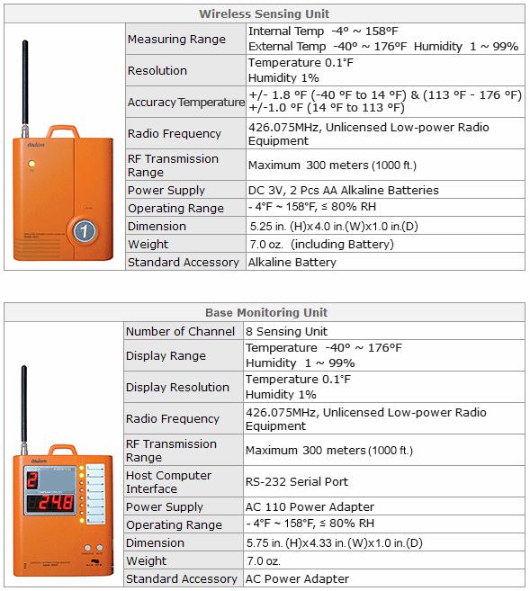
21 Specifications 21
22 INFORMATION TO THE USER This equipment has been tested and found to comply with the limits for a Class B digital device, pursuant to part 15 of the FCC Rules. These limits are designed to provide reasonable protection against harmful interference in a residential installation. This equipment generates uses and can radiate radio frequency energy and, if not installed and used in accordance with the instructions, may cause harmful interference to radio communications. However, there is no guarantee that interference will not occur in a particular installation. If this equipment does cause harmful interference to radio or television reception, which can be determined by turning the equipment off and on, the user is encouraged to try to correct the interference by one more of the following measures: -Reorient or relocate the receiving antenna. -Increase the separation between the equipment and receiver. -Connect the equipment into an outlet on a circuit different from that to which the receiver is connected. -Consult the dealer or an experienced radio/tv technician for help. WARNING The manufacturer is not responsible for any Radio or TV interference caused by unauthorized modifications to this equipment. Such modifications could void the user s authority to operate the equipment. 22
23 Warranty This product is warranted to be free from defects in material or workmanship for 1 year from the date of purchase. During the warranty period Spectrum will, at its option, either repair or replace products that prove to be defective. This warranty is void if the Spectrum products have been damaged by customer error or negligence, or if there has been an unauthorized modification. Returning Products to Spectrum Before returning a failed unit, you must obtain a Returned Goods Authorization (RGA) number from Spectrum. You must ship the product(s), properly packaged against further damage, back to Spectrum at your expense. Clearly mark the RGA number on the outside of the package. Spectrum is not responsible for any package that is returned without a valid RGA number or for the loss of the package by any shipping company. 23
READ ME FIRST DIY WIRELESS ALERT. Add-on Alert Sensor. For Swann Wireless Alert systems. Instruction Manual
 READ ME FIRST DIY WIRELESS ALERT Add-on Alert Sensor For Swann Wireless Alert systems EN Instruction Manual 2 About this Manual The content in this manual is for information purposes only and is subject
INSTRUCTIONS FOR. Wireless Refrigerator Freezer Thermometer (#10378)
") CONTENTS Unpacking Instructions... 2 Package Contents... 2 Product Registration... 2 Features & Benefits: Sensors... 2 Features & Benefits: Display... 3 Setup... 4 Install or Replace Batteries... 4 Temperature
CONTENTS Unpacking Instructions... 2 Package Contents... 2 Product Registration... 2 Features & Benefits: Sensors... 2 Features & Benefits: Display... 3 Setup... 4 Install or Replace Batteries... 4 Temperature
Home Doorway Alert Kit
 READ ME FIRST DIY WIRELESS ALERT Home Doorway Alert Kit EN Instruction Manual 2 About this Manual The content in this manual is for information purposes only and is subject to change without notice. While
Model: T83653v2 Instruction manual DC: WIRELESS COLOR FORECAST STATION Mold Risk for Forecast Station & Indoor Remote Sensor Location
 Model: T83653v2 Instruction manual DC: 012916 WIRELESS COLOR FORECAST STATION Mold Risk for Forecast Station & Indoor Remote Sensor Location FRONT VIEW Time, Alarm + Calendar Indoor Humidity & Temperature
READ ME FIRST DIY WIRELESS ALERT. Driveway Alert Kit. Instruction Manual
 READ ME FIRST DIY WIRELESS ALERT Driveway Alert Kit EN Instruction Manual 2 About this Manual The content in this manual is for information purposes only and is subject to change without notice. While
Ambient Weather WS-0211 Wireless Wendy the Weather Wizard User Manual
 Ambient Weather WS-0211 Wireless Wendy the Weather Wizard User Manual Table of Contents 1. Introduction... 2 2. Getting Started... 2 2.1 Parts List... 2 2.2 Recommend Tools... 2 2.3 Thermometer Sensor
Model: v2 Quick Setup Guide DC: Atomic Projection Alarm with Indoor and Outdoor Temperature
 Model: 616-146v2 Quick Setup Guide DC: 090116 Atomic Projection Alarm with Indoor and Outdoor Temperature Snooze/Backlight BUTTONS Time, Alarm with Snooze, & Calendar Projection Arm Rotates 180 Indoor/Outdoor
WIRELESS COLOR FORECAST STATION
 Model: 308-1412S Manual DC: 080217 WIRELESS COLOR FORECAST STATION SENSOR TX141TH-Bv2 LED TX Sensor Battery 2 AA Buttons 3 AAA AC Power USB PORT Model: 308-1412S www.lacrossetechnology.com/support Page
WIRELESS COLOR FORECAST STATION
 Model: S88907 Instruction Manual DC: 071817 WIRELESS COLOR FORECAST STATION TX141TH-Bv2 Sensor Table of Contents INITIAL SETUP... 3 LCD FEATURES... 4 BUTTONS... 4 (Down) Button... 4 TIME SET Button...
Wireless Weather Station. Table of Contents
 Wireless Weather Station Model: T83646v2 Instructional Manual DC:071916 For online video support: http://bit.ly/laxtechtalk Table of Contents LCD Features... Buttons... Setup... Set Time, Date etc....
Digital Cooking Thermometer models / 00282
 Instruction Manual Digital Cooking Thermometer models 00278 / 00282 CONTENTS Unpacking Instructions... 2 Package Contents... 2 Product Registration... 2 Features & Benefits... 2 Setup... 4 Install or Replace
READ ME FIRST DIY WIRELESS ALERT. Gate Alert Kit. Instruction Manual
 READ ME FIRST DIY WIRELESS ALERT Gate Alert Kit EN Instruction Manual AT A GLANCE Thank you for choosing the Gate Alert Kit from Swann. It's the ideal system to detect unwanted access into a restricted
External Wireless Sounder
 External Wireless Sounder WL S50 Installation and Programming Instructions 2 Wireless Sounder Instructions Table of Contents Introduction... 4 Operational Functions... 4 Alarm / Tamper Indication...4 Low
Model: WS-9133U-IT Quick Setup Guide DC: WIRELESS FORECAST STATION
 Model: WS-9133U-IT Quick Setup Guide DC: 041916 WIRELESS FORECAST STATION Time 12/24hr + Alarm Indoor Temp. ºF/ºC Forecast Icon + Tendency Arrow Outdoor Temp. ºF/ºC Wall Hanging Hole TX37U-IT Temperature
WIRELESS WEATHER STATION
 WIRELESS WEATHER STATION Model: 308-1711BL Instruction Manual DC: 071317 TABLE OF CONTENTS INITIAL SETUP... 2 LCD FEATURES... 3 BUTTON Functions... 3 SET TIME, DATE, ETC.... 4 SET TIME ALARM... 5 ACTIVATE/DEACTIVATE
Wireless Color Weather Station
 Wireless Color Weather Station For online video support: http://bit.ly/laxtechtalk Model: M84282 DC: 071117 Table of Contents Button Function Explanation... Setup... Settings Menu... Fahrenheit Celsius...
DIGITAL ATOMIC WALL CLOCK
 DIGITAL ATOMIC WALL CLOCK Model: 513-149 Instruction Manual DC: 111915 Table of Contents INITIAL SETUP... 2 LCD FEATURES... 3 BUTTONS (back view)... 3 SET TIME, DATE, ETC.... 3 FAHRENHEIT/CELCIUS TEMPERATURE
Honeywell Temperature & Humidity Sensor with LCD
 Honeywell Temperature & Humidity Sensor with LCD TABLE OF CONTENTS INTRODUCTION 3 PRODUCT OVERVIEW 4 BEFORE YOU BEGIN 5 BATTERY INSTALLATION 7 LOW BATTERY WARNING 7 PLACEMENT OF THE REMOTE SENSOR 7 GETTING
High Resolution Display WIRELESS COLOR WEATHER STATION
 High Resolution Display WIRELESS COLOR WEATHER STATION Model: S88785 Instruction Manual DC: 070717 SIDE VIEW FRONT VIEW Outdoor Temp, humidity + Trends AC Power Jack DC 5.0V Day/Night Forecast + Trend
Honeywell. Wireless Rain Gauge with Indoor. Temperature (TC152) USER MANUAL TABLE OF CONTENTS INTRODUCTION 3 PRODUCT OVERVIEW 4 REMOTE RAIN GAUGE 7
 USER MANUAL TABLE OF CONTENTS INTRODUCTION 3 PRODUCT OVERVIEW 4 REMOTE RAIN GAUGE 7") TABLE OF CONTENTS INTRODUCTION 3 PRODUCT OVERVIEW 4 REMOTE RAIN GAUGE 7 BEFORE YOU BEGIN 9 BATTERY INSTALLATION 10 LOW BATTERY WARNING 11 HOW TO USE THE TABLE STAND 11 GETTING STARTED 11 Honeywell Wireless
TABLE OF CONTENTS INTRODUCTION 3 PRODUCT OVERVIEW 4 REMOTE RAIN GAUGE 7 BEFORE YOU BEGIN 9 BATTERY INSTALLATION 10 LOW BATTERY WARNING 11 HOW TO USE THE TABLE STAND 11 GETTING STARTED 11 Honeywell Wireless
Model: S88907 Instruction Manual DC: WIRELESS COLOR WEATHER STATION
 Model: S88907 Instruction Manual DC: 072314 WIRELESS COLOR WEATHER STATION FRONT VIEW SIDE BUTTONS Time Calendar + Alarm Color Animated Forecast + Tendency Remote Humidity & Temperature with Trend Indoor
Owner s Manual. PIR-1 IR Learner
 Owner s Manual PIR-1 IR Learner PIR-1 Owner s Manual 2010-2013 Universal Remote Control, Inc. The information in this owner s manual is copyright protected. No part of this manual may be copied or reproduced
Atomic Digital Clock with Temperature and Moon Phase
 Atomic Digital Clock with Temperature and Moon Phase For online video support: http://bit.ly/laxtechtalk Model: 513-1417AL D.C. 122016 Protected under U.S. Patents: 5,978,738 6,076,044 RE43903 Setup Power
Driveway Alarm INSTALLATION MANUAL.
 WIRELESS Driveway Alarm INSTALLATION MANUAL Kit Includes: A C A. Transmitter B. Sensor C. Receiver D. Transformer E. Mounting post (3 pcs) E D How It Works: The electromagnetic sensor detects vehicles
Thermometer model 02059
 Instruction Manual Thermometer model 02059 pm CONTENTS Unpacking Instructions... 2 Package Contents... 2 Product Registration... 2 Features & Benefits: Sensor... 2 Features & Benefits: Display... 3 Setup...
Atomic Projection Alarm Clock
 Model: 616-143 Quick Setup Guide DC: 072915 Atomic Projection Alarm Clock Snooze/Backlight Projection Lens Projection Arm Rotation (Front and Back) FRONT VIEW Buttons Projection Focus BACK VIEW AC Power
Model: WS-8147U-IT Instruction Manual DC: ATOMIC DIGITAL CLOCK WITH MOON PHASE
 Model: WS-8147U-IT Instruction Manual DC: 011816 ATOMIC DIGITAL CLOCK WITH MOON PHASE Time, Alarm, + WWVB Icon Indoor Temp/Hum, Weekday, Date, Moon Phase, + Outdoor Temp. Two AA Batteries Foldout Stand
Ambient Weather WS-091-C Three Channel Display Wireless Thermometer (Console Only) User Manual
 User Manual") Ambient Weather WS-091-C Three Channel Display Wireless Thermometer (Console Only) User Manual Table of Contents 1 Introduction... 2 2 Getting Started... 2 Parts List... 3 2.2 Display Console Set Up...
Ambient Weather WS-091-C Three Channel Display Wireless Thermometer (Console Only) User Manual Table of Contents 1 Introduction... 2 2 Getting Started... 2 Parts List... 3 2.2 Display Console Set Up...
Wireless Rain Gauge with Indoor Temperature
 TABLE OF CONTENTS INTRODUCTION 3 PRODUCT OVERVIEW 4 7 BEFORE YOU BEGIN 9 BATTERY INSTALLATION 10 Wireless Rain Gauge with Indoor Temperature LOW BATTERY WARNING 11 HOW TO USE THE TABLE STAND 11 GETTING
WIRELESS FORECAST STATION
 Model: B86012 Instruction Manual DC: 072915 WIRELESS FORECAST STATION Table of Contents INITIAL SETUP... 2 LCD FFEATURES... 3 BUTTONS... 3 SET TIME, DATE, ETC.... 4 BACKLIGHT... 6 CITY SELECTION-SUNRISE/SUNSET
Projection Alarm Clock
 Projection Alarm Clock Model: W8923v2 Instructional Manual DC: 0676 For online video support visit: http://bit.ly/laxtechtalk Table of Contents LCD Features... Buttons... Setup... Set Time, Date, etc....
Model: Quick Setup Guide DC: Atomic Projection Alarm Clock. Projection Lens. Buttons. Snooze/Backlight
 Model: 616-143 Quick Setup Guide DC: 083017 Atomic Projection Alarm Clock Snooze/Backlight Projection Lens Projection Arm Rotation (Front and Back) Buttons Projection Focus 5.0 VAC Power Jack 616-143 www.lacrossetechnology.com/support
Model: C Instruction Manual DC: WIRELESS COLOR WEATHER STATION
 Model: 308-1425C Instruction Manual DC: 102314 WIRELESS COLOR WEATHER STATION FRONT VIEW Time Calendar + Alarm REMOTE SENSOR TX141TH-Bv2 Color Animated Forecast + Tendency Indoor Humidity & Temperature
Ambient Weather WS-16 8-Channel Wireless Thermometer with Min/Max Display User Manual
 Ambient Weather WS-16 8-Channel Wireless Thermometer with Min/Max Display User Manual Table of Contents 1 Introduction... 2 2 Getting Started... 3 2.1 Parts List... 3 2.2 Thermometer Sensor Set Up... 3
Digital Refrigerator/Freezer Thermometer model 00986
 Instruction Manual Digital Refrigerator/Freezer Thermometer model 00986 CONTENTS Unpacking Instructions... 2 Package Contents... 2 Product Registration... 2 Features & Benefits: Sensors... 2 Features &
WIRELESS COLOR WEATHER STATION
 WIRELESS COLOR WEATHER STATION Model: 308-1414 Quick Setup Guide DC: 100814 FRONT VIEW Outdoor Temp + Trends Outdoor Humidity + Trend & Temp Alerts Animated Forecast + Trends Indoor Temp + Trends Indoor
Model: Av2 Quick Setup Guide DC: Atomic Projection Alarm Clock
 BUTTONS Model: 616-146Av2 Quick Setup Guide DC: 111815 Atomic Projection Alarm Clock Snooze/Backlight Time, Alarm with Snooze Projection Arm Rotates 180 Indoor Temperature + Trends Moon Phase + Calendar
Mood Light and Nature Sound Alarm Clock
 Mood Light and Nature Sound Alarm Clock For online video support: http://bit.ly/laxtechtalk Model: C83117 DC: 031518 TABLE OF CONTENTS 3 3 4 4 4 4 5 5 5 6 6 6 6 7 7 7 7 8 8 9 9 9 9 10 10 Power Up Settings
WIRELESS TEMPERATURE & HUMIDITY STATION INSTRUCTION MANUAL
 WIRELESS TEMPERATURE & HUMIDITY STATION INSTRUCTION MANUAL MODEL: S82967 DC: 071118 FIND MANUALS, FAQS, AND MORE UNDER THE SUPPORT TAB HERE: www.lacrossetechnology.com/s82967 TABLE OF CONTENTS 3. Power
WIRELESS COLOR WEATHER STATION
 Model: 308-1414W/308-1414B Instruction Manual DC: 071117 WIRELESS COLOR WEATHER STATION FRONT VIEW Outdoor Temp + Trends Outdoor Humidity + Trend & Temp Alerts Animated Forecast + Trends Indoor Temp +
Ambient Weather WS-09 8-Channel Wireless Refrigerator/Freezer Thermometer User Manual
 Ambient Weather WS-09 8-Channel Wireless Refrigerator/Freezer Thermometer User Manual Table of Contents 1. Introduction... 2 2.Getting Started... 2 2.1 Parts List... 2 2.2 Probe Thermometer Sensor Set
FEATURES AND SPECIFICATIONS
 PRECISE TEMP WIRELESS MULTI-ZONE THERMOMETER and HYGROMETER With CLOCK Model No. 91756 User's Manual BASE STATION REMOTE SENSOR FEATURES AND SPECIFICATIONS BASE STATION Indoor / wireless outdoor temperature,
Ambient Weather WS Channel Wireless Thermometer with Min/Max Display User Manual
 Ambient Weather WS-0802 8-Channel Wireless Thermometer with Min/Max Display User Manual Table of Contents 1 Introduction... 1 2 Getting Started... 3 2.1 Parts List... 3 2.2 Thermometer Sensor Set Up...
Model: Quick Setup Guide DC: Atomic Projection Alarm Clock. Projection Lens. Buttons. Snooze/Backlight
 Model: 616-143 Quick Setup Guide DC: 051916 Atomic Projection Alarm Clock Snooze/Backlight Projection Lens Projection Arm Rotation (Front and Back) Buttons Projection Focus 5.0 VAC Power Jack Battery Cover
Model: M Instruction Manual DC: WIRELESS COLOR WEATHER STATION Mold Risk for Weather Station & Indoor Remote Sensor Location
 Model: 308-1414M Instruction Manual DC: 100814 WIRELESS COLOR WEATHER STATION Mold Risk for Weather Station & Indoor Remote Sensor Location Color Animated Forecast with Tendency (All icons shown here)
RGR150 USER S MANUAL. Wireless Rain Gauge with Thermometer and Clock
 RGR150 manual-final-091908:layout 1 9/19/08 8:59 AM Page 1 RGR150 USER S MANUAL Wireless Rain Gauge with Thermometer and Clock INTRODUCTION Thank you for selecting this Wireless Rain Gauge. This device
HSD-200Z Z-Wave Motion Sensor
 HSD-200Z Z-Wave Motion Sensor The HSD-200Z is a Z-Wave TM enabled device and is fully compatible with any Z-Wave TM enabled network. Z-Wave TM enabled devices displaying the Z-Wave TM logo can also be
Wireless Driveway and Intruder Alert
 Wireless Driveway and Intruder Alert USER MANUAL SFA600 PLEASE READ THIS USER MANUAL COMPLETELY BEFORE OPERATING THIS UNIT AND RETAIN THIS BOOKLET FOR FUTURE REFERENCE. COMPLIANCE WITH FCC REGULATIONS
Ion Gateway Cellular Gateway and Wireless Sensors
 Page 1 of 9 Account & Network Setup If this is your first time using the Ion Gateway online system site you will need to create a new account. If you have already created an account you can skip to the
Model:T83646v2 Quick Setup Guide DC: WIRELESS WEATHER STATION
 Model:T83646v2 Quick Setup Guide DC: 012015 WIRELESS WEATHER STATION FRONTVIEW Time and Moon Phase Indoor Temp/Humidity with Trend, Mold Risk, + Temperature Alerts. Calendar + Time Alarm Remote Temp/Humidity
Instruction Manual. AcuRite Atlas. Indoor Display model 06061
 Instruction Manual AcuRite Atlas Indoor Display model 06061 How It Works AcuRite Atlas is an environmental monitoring station that delivers key information on current outdoor conditions in your exact location.
Wireless External Alarm
 Wireless External Alarm Model: SA-001S User s Instructions TABLE OF content INTRODUCTION... 2 INSTALLATION... 2-4 PROGRAMMING LEARN REMOTE OR SENSORS OR CONTROL PANEL... 4-6 ERASE REMOTE OR SENSOR OR CONTROL
Color Forecast Station. Table of Contents
 Color Forecast Station Model: C884 Instructional Manual DC: 01816 View online setup video at: http://bit.ly/laxtechtalk Table of Contents LCD Features... Setup... Atomic Time... Set Language, Time, Date
Room Monitor SAVE THIS MANUAL FOR FUTURE REFERENCE.
 Instruction Manual Room Monitor model 00276RM CONTENTS Unpacking Instructions... 2 Package Contents... 2 Product Registration... 2 Features & Benefits... 3 Setup... 4 Placement Guidelines... 5 Using the
Instruction Manual. AcuRite Atlas. Indoor Display model 06061
 Instruction Manual AcuRite Atlas Indoor Display model 06061 How It Works AcuRite Atlas is an environmental monitoring station that delivers key information on current outdoor conditions in your exact location.
Wireless Rain Gauge with Rainfall Memory and Digital Clock MODEL: RGR382
 Wireless Rain Gauge with Rainfall Memory and Digital Clock MODEL: RGR382 EU-Declaration of conformity... 8 Fcc statement... 8 Declaration of Conformity... 9 USER MANUAL CONTTS Introduction... 2 Main unit
Ambient Weather RC-8365 ClearView Radio Controlled Projection Clock with Indoor Temperature User Manual
 Ambient Weather RC-8365 ClearView Radio Controlled Projection Clock with Indoor Temperature User Manual Table of Contents 1. Introduction... 1 2. Warnings... 2 3. Getting Started... 2 3.1 Product Features...
9000P Wireless Alarm Owner s Manual
 9000P Wireless Alarm Owner s Manual Table of Contents Introduction... 3 Intended Use... 3 System Functionality... 3 Arming your Alarm... 3 Arm Home...3 Arm Away...4 Alarm Triggering... 4 Disarming your
IMPORTANT. Display for 5-in-1 Weather Sensor model 06005RM/1010RX SAVE THIS MANUAL FOR FUTURE REFERENCE. Package Contents
 Instruction Manual Display for 5-in-1 Weather Sensor model 06005RM/1010RX Package Contents 1. Display unit with tabletop stand 2. Instruction manual This product requires an AcuRite 5-in-1 Weather Sensor
Wireless Weather Station with Bluetooth Speaker and Atomic Time & Date
 Model: S87078 Instructional Manual DC: 062915 Wireless Weather Station with Bluetooth Speaker and Atomic Time & Date Table Of Contents Button Location... 1 Initial Setup... 2 LCD Layout... 3 Bluetooth
Atomic Digital Wall Clock
 Model: BBB87269 Instruction Manual DC:102015 Atomic Digital Wall Clock Table of Contents Welcome... Get Started... Button Functions... Settings: Time, Date, etc.... Time Zone Settings and 12/24 Hour Time...
WIRELESS MULTI-ZONE DIGITAL THERMOMETER WITH RADIO CONTROLLED CLOCK. Model No (SF Version) Instruction Manual
 Instruction Manual") WIRELESS MULTI-ZONE DIGITAL THERMOMETER WITH RADIO CONTROLLED CLOCK Model No. 91049-1 (SF Version) Instruction Manual BASE STATION REMOTE SENSOR FEATURES AND SPECIFICATIONS BASE STATION Indoor / RF outdoor
WIRELESS MULTI-ZONE DIGITAL THERMOMETER WITH RADIO CONTROLLED CLOCK Model No. 91049-1 (SF Version) Instruction Manual BASE STATION REMOTE SENSOR FEATURES AND SPECIFICATIONS BASE STATION Indoor / RF outdoor
IN-OUT Thermometer with Cable Free Sensor and Clock
 IN-OUT Thermometer with Cable Free Sensor and Clock CONTTS (MODEL: RAR232) USER MANUAL Introduction... 1 Product overview... 2 Main unit... 2 Remote unit... 3 Table stand and wall mounting... 3 Main unit...
Ambient Weather RC-8365 ClearView Radio Controlled Projection Clock with Indoor and Outdoor Temperature User Manual
 Ambient Weather RC-8365 ClearView Radio Controlled Projection Clock with Indoor and Outdoor Temperature User Manual Table of Contents 1. Introduction... 1 2. Warnings... 2 3. Getting Started... 2 3.1 Product
Installation and ZONES: Operation Manual. Model: ON STI-34108
 N.O. COM N.C. + 12 V - IN + 12 V - OUT 500 ma 300 ma PLUG IN ADAPTER 12 V 500mA Trigger Output 12 V 75mA N.O. COM N.C. + 12 V - IN + 12 V - OUT 500 ma 300 ma PLUG IN ADAPTER 12 V 500mA Trigger Output 12
Installer Guide smart connect
 Installer Guide smart connect TM 7390 Wireless Remote Indoor Sensor Please read all instructions before proceeding. The wireless remote indoor sensor monitors temperature at a remote indoor location and
Instruction Manual. AcuRite Atlas Outdoor Device model 06059
 Instruction Manual AcuRite Atlas Outdoor Device model 06059 How It Works Set Up Your AcuRite Atlas AcuRite Atlas is an environmental monitoring station that delivers key information on current outdoor
Ambient Weather RC-8487 ClearView Radio Controlled Travel Alarm Clock with Indoor Temperature User Manual
 Ambient Weather RC-8487 ClearView Radio Controlled Travel Alarm Clock with Indoor Temperature User Manual Table of Contents 1. Introduction... 1 2. Getting Started... 2 2.1 Display Features... 2 2.2 Parts
WS-9117U-IT Wireless 915 MHz Temperature Station. Instruction Manual
 WS-9117U-IT Wireless 915 MHz Temperature Station Instruction Manual 1 TABLE OF CONTENTS Topic Inventory of Contents Quick Setup Detailed Setup Guide Battery Installation Setting the Time Features Minimum
BBQ THERMOMETER DESCRIPTION OF PARTS. MODEL NO.: AW129/AWR129 Instruction Manual
 BBQ THERMOMETER MODEL NO.: AW129/AWR129 Instruction Manual DESCRIPTION OF PARTS A. POWER BUTTON Turns the unit on/off. Press and hold for 2 seconds to activate unit. B. SELECT BUTTON Selects the type of
2017 EcoFactor, Inc.
 User Guide 2017 EcoFactor, Inc. Introduction The thermostat supports up to 2 stages of heating and 2 stages of cooling for conventional systems, and 2 stages of heating/ cooling for heat pumps, with and
Atomic Digital Office Clock
 Atomic Digital Office Clock Model: 3-49-INT Instructional Manual DC: 0 Table of Contents LCD Features... Custom Display Modes... Setup... Atomic Time Signal... Settings: Language, Time, Date, etc.... Set
Wireless Weather Station
 Welcome! -------------- Congratulations on your new and welcome to the La Crosse Technology family! This product was designed with you in mind by our hometown team of weather enthusiasts based in La Crosse,
Weather Forecaster models 75077/75107
 Instruction Manual Weather Forecaster models 75077/75107 CONTENTS Unpacking Instructions... Package Contents... Product Registration... Features & Benefits: Sensor... Features & Benefits: Display... 3
Digital Thermometer with Ice Alert and Clock
 Digital Thermometer with Ice Alert and Clock Model: RAR381 USER MANUAL Specifications... 8 About Oregon Scientific... 8 EU-Declaration of Conformity... 9 FCC Statement... 9 Declaration of Conformity...
ATOMIC DIGITAL CLOCK. Time and Alarm
 Model: 515-1316 Instruction Manual DC: 052015 ATOMIC DIGITAL CLOCK Time and Alarm Month, Date, & Weekday Buttons 3 C Batteries Model: 515-1316 www.lacrossetechnology.com/support Page 1 Get Started Step
PRODUCT DIAGRAM PACKAGE CONTENTS
 PRODUCT DIAGRAM PACKAGE CONTENTS After receiving the product, please inventory the contents to ensure you have all the proper parts, as listed below. If anything is missing or damaged, please contact Monoprice
For Android devices MYQ-G0301 MYQ-G0301C MYQ-G0301D MYQ-G0301LA
 Smart Smart Garage Garage Hub Hub Manual Manual For Android devices MYQ-G0301 MYQ-G0301C MYQ-G0301D MYQ-G0301LA by Before You Start To reduce the risk of SEVERE INJURY to persons: DO NOT enable the MyQ
PRODUCT DIAGRAM PACKAGE CONTENTS
 PRODUCT DIAGRAM PACKAGE CONTENTS After receiving the product, please inventory the contents to ensure you have all the proper parts, as listed below. If anything is missing or damaged, please contact Monoprice
Installation and Operation Manual. Model: STI TRIGGERED OUTPUT PLUG 12VDC, 75mA, 3 SEC. EMBOSSED PROGRAMMING
 EMBOSSED PROGRAMMING SWITCHES 1-8 ANTENNAS ZONES: LEFT BUTTON CALL Embossed Programming Instructions: Installation and Operation Manual STI 8-Channel 1 - MIRROR MASTER OFF/ON RIGHT BUTTON FRONT COVER RESTORE
Multi-Channel Indoor-Ooutdoor Thermohygrometer with Cable Free TM Sensor & ExactSet TM Clock
 Remote Therm-Hygro RMR136HG Tested To Comply With FCC Standards FOR HOME OR OFFICE USE C E GB Multi-Channel Indoor-Ooutdoor Thermohygrometer with Cable Free TM Sensor & ExactSet TM Clock MODEL: RMR-136HG
IFT-RC150 IntelliFire Touch Remote Control Installation Instructions
 IFT-RC150 IntelliFire Touch Remote Control Installation Instructions Leave this manual with party responsible for use and operation. 1. Introduction The IFT-RC150 is a wall mounted device that is designed
Model: C87207 / C87061 Instruction Manual DC: DUAL ALARM CLOCK
 Model: C87207 / C87061 Instruction Manual DC: 081115 DUAL ALARM CLOCK FRONT VIEW USB Charge Port 1 Amp Output BACK VIEW SIDE VIEW Battery Compartment 2 AAA AC Power Jack Model: C87207 / C87061 www.lacrossetechnology.com/support
1126 Series Ceiling Mount PIR Motion Detector
 Installation Sheet 1126 Series Ceiling Mount PIR Motion Detector Description The 1126 Series PIR (Passive Infrared) Motion Detectors are a compact wireless PIR. The 1126 Series offer 360, Wide Angle, or
The Digital Door Viewer! User Manual. Motion Activated Sensor MAS 100
 The Digital Door Viewer! User Manual Motion Activated Sensor MAS 100 01- MAS100 Thank you for purchasing Motion Activated Sensor for Brinno PeepHole Viewer! Brinno MAS100 is an extension accessory for
For ios devices MYQ-G0301 MYQ-G0301C MYQ-G0301-D MYQ-G0301LA
 Smart Smart Garage Garage Hub Hub Manual Manual For ios devices MYQ-G0301 MYQ-G0301C MYQ-G0301-D MYQ-G0301LA by Before You Start To reduce the risk of SEVERE INJURY to persons: DO NOT enable the MyQ Smart
Ambient Weather WS-28 Indoor/Outdoor Thermometer with Daily Min/Max Display User Manual
 Ambient Weather WS-28 Indoor/Outdoor Thermometer with Daily Min/Max Display User Manual Table of Contents 1 Introduction... 2 2 Getting Started... 2 2.1 Parts List... 2 3 Display Console Layout... 3 4
Model: B Instruction Manual DC: WIRELESS COLOR WEATHER STATION
 Model: 308-1425B Instruction Manual DC: 100814 WIRELESS COLOR WEATHER STATION FRONT VIEW SIDE BUTTONS WWVB Time Color Animated Forecast + Tendency Outdoor Temperature with Trend Indoor Temperature with
Campers Alert TM Portable System Hunters Alert TM Portable System
 Campers Alert TM Portable System Hunters Alert TM Portable System USER MANUAL READ THIS ENTIRE MANUAL PRIOR TO INSTALLATION AND OPERATION We thank you for purchasing this Driveway Alert System. All our
Wireless Home Appliance Timer Remote Control Kit
 Warning: Changes or modifications to this unit not expressly approved by the party responsible for compliance could void the user authority to operate the equipment. NOTE : This equipment has been tested
Weather Station model 02001
 Instruction Manual Weather Station model 02001 CONTENTS Unpacking Instructions... 2 Package Contents... 2 Product Registration... 2 Features & Benefits: Sensor... 2 Features & Benefits: Display... 3 Setup...
IMPORTANT. Questions? Contact Customer Support at (877) or visit 5-in-1 PRO+ Weather Sensor model
 or visit 5-in-1 PRO+ Weather Sensor model") Instruction Manual 5-in-1 PRO+ Weather Sensor model 06014 Package Contents 1. 5-in-1 PRO+ Weather Sensor 2. Mounting Hardware 3. Sensor Mounting Bracket 4. Instruction Manual IMPORTANT PRODUCT MUST BE
Instruction Manual 5-in-1 PRO+ Weather Sensor model 06014 Package Contents 1. 5-in-1 PRO+ Weather Sensor 2. Mounting Hardware 3. Sensor Mounting Bracket 4. Instruction Manual IMPORTANT PRODUCT MUST BE
Multi-Channel Indoor & Outdoor Thermometer with Cable Free Sensor & Radio Controlled Clock
 Remote Thermometer RMR166 Tested To omply With F Standards FOR HOME OR OFFIE USE -D E Multi-hannel Indoor & Outdoor Thermometer with able Free Sensor & Radio ontrolled lock MODEL: RMR166 USER'S MANUAL
WIRELESS WEATHER STATION WIRELESS WEATHER STATION. Please Note. We are unable to supply Additional Sensors for This Weather Station C-8105/C-8145
 WIRELESS WEATHER STATION Please Note WIRELESS WEATHER STATION C-8105/C-8145 USER S INSTRUCTIONS We are unable to supply Additional Sensors for This Weather Station P17810500050 The multifunctional weather
Operation and Maintenance Manual OM 897-3
 Operation and Maintenance Manual OM 897-3 Wireless Temperature Control Use with factory or field installed Daikin WSHP wireless RCN Group: WSHP Document PN: 910203510 Date: March 2017 Part No. 668898001
Wireless Occupancy Sensor, Ceiling Mount (WOS2-CM)
") 21233 Wireless Occupancy Sensor, Ceiling Mount Installation Instructions The Daintree Networks ceiling mounted Wireless Occupancy Sensor operates seamlessly within the ControlScope Manager (CSM), the Daintree
21233 Wireless Occupancy Sensor, Ceiling Mount Installation Instructions The Daintree Networks ceiling mounted Wireless Occupancy Sensor operates seamlessly within the ControlScope Manager (CSM), the Daintree
Weather Day & Night Model: BAR339DP / BAR339DPA / BAR339DPU / BAA339DPH
 Weather Day & Night Model: BAR339DP / BAR339DPA / BAR339DPU / BAA339DPH CONTENTS USER MANUAL Overview...2 Front View...2 Back View...3 Remote Sensor...3 Getting Started...3 Main Unit Installation...3 Remote
Thermometer with Wired Sensor
 Instruction Manual Thermometer with Wired Sensor model 02042 CONTENTS Unpacking Instructions... 2 Package Contents... 2 Product Registration... 2 Features & Benefits... 3 Setup... 4 Temperature Units...
Table of Contents. What s in the Box... 3 Power Requirements... 4 Quick Setup... 5 Lighting Guide With Ring, you re Always home.
 Chime Setup Guide Table of Contents 2 What s in the Box... 3 Power Requirements... 4 Quick Setup... 5 Lighting Guide... 6 With Ring, you re Always home. What s in the Box 3 1. Ring Chime 2. Wall plugs
Cable Free Weather Station with Thermo-Hygrometer and Radio controlled clock
 Cable Free Weather Station with Thermo-Hygrometer and Radio controlled clock MODEL: BAR938HGA USER S MANUAL INTRODUCTION Congratulations on your purchasing of BAR938HGA Cable Free Weather Station with