MAG2/4. AL MAG2 Soft. Version 2.1 MAG4 Soft.Version 2.0 USER MANUAL
|
|
|
- Hector Payne
- 5 years ago
- Views:
Transcription


1 FIRE CONTROL PANEL MAG2/4 USER MANUAL AL MAG2 Soft. Version 2.1 MAG4 Soft.Version 2.0 READ THIS MANUAL BEFORE CONNECTING THE EQUIPMENT AND KEEP IT SAFE FOR FUTURE REFERENCE. To call our technical support line dial +44 (0)
2 INSTALLER Instructions Contents Page General Information... 2 Using the Mag 2/4 controls... 3 Indicators / Outputs... 3 Engineers Facilities... 3 Installing the Panel... 4 Testing the Panel... 4 Engineers Facilities... 6 Connecting the Additional Facilities... 7 Specification... 8 Notes... 9 Connection Circuits MAG 2/ Guarantee Fire Alarm Record Service Record Fire Alarm Event Log WARNING This manual contains information on limitations regarding product use and function and information on the limitations as to liability of the manufacturer. The entire manual should be carefully read. General Information The system is to be installed by a qualified person to the latest Fire Alarm and Installation Regulations which are mandatory in the applicable country of installation. Before commencing the installation of this Fire Alarm Panel, ensure it is sited in a position, which is visible to the Fire Brigade when entering the premises, and where ease of access is provided for users and service engineers. Space must be available to easily open external and internal doors. The Electrical Supply to the panel must be isolated and must not be capable of being accidentally switched off. A Lockable Switch fuse Unit positioned within 2 meters of the panel should be clearly labelled FIRE ALARM - DO NOT SWITCH OFF. EN 54-2 compatible panels. All specifications are subject to change without notice. 2
3 Using the MAG 2/4 Controls Refer to the instructions on the inside of the outer door. Indications / Outputs NORMAL: The green LED next to the power Supply 230V AC will be illuminated. FIRE: Two integrated red status FIRE LED s and a zone identification LED will flash together on receipt of a FIRE condition and become steady after the Silence Alarm button is pressed. An internal buzzer will operate until silenced. The external sounders will operate. The FIRE relay will energize. FAULT: A yellow General Fault LED will always illuminate together with an external or internal identification LED. An internal buzzer will sound. The FAULT relay will de-energize. Faults are monitored as follows: Zone fault - open or short circuit. Detector head removed. Sounder Circuit One fault - open or short circuit, reverse connected sounder, or bad sounder parameters. Sounder Circuit Two fault - open or short circuit, reverse connected sounder, or bad sounder parameters. A.C. Loss or Battery charger fault. ( A.C. Loss means Mains Supply) Battery Loss. Low Battery condition. 24V DC Supply fault. Processor fault. Auxiliary supply fault. Short circuit to earth. All fuses are monitored and will cause a fault condition should they fail. Selecting an Engineers Facility will indicate and announce a Fault condition at the panel. NOTE: FAULT CONDITIONS WILL NOT BE ANNOUNCED INSTANTLY. THERE WILL BE A SHORT DELAY WHICH WILL VARY FROM CONDITION TO CONDITION. FAULTS WHEN CLEARED WILL AUTOMATICALLY RESET AT THE PANEL. Engineers Facilities: MAG 2/4 has the ability to select various facilities to assist the engineer during installation and testing of the system. These facilities include: Zone Test - Individual zones can be tested and activated without the need to return to the panel to effect a RESET. This is done automatically by the panel. Isolate Sounders - System can be tested without operating the Sounder circuits. Disable / Enable Zone - Each zone can be disabled / enabled. 3
4 Installing the Panel Decide the best location for the panel position, with an ambient temperature between 0 degrees C and 40 degrees C., away from heating systems, environmental dust and potential water ingress. Remove all packaging. Inspect the panel for any damage. Carefully remove the outer cover, by inserting unscrewing the two allen screws. Stow the cover in a safe position. Inspect the internal PCB and make sure the internal components are firmly in place. Observe the main PCB chassis and the associated securing screw, located in the front of the terminal blocks. Unfasten the chassis securing screw and remove the chassis. Stow in a safe location. Choose which cable entry points to knock out and carefully remove the knock-outs. Observe the top center fixing location at the back of the panel. Stow the back box in a safe position. Drill the wall to suit the back box center fixing position, plug and insert a fixing screw. Temporally hang the back box from the fixing screw and mark out the two bottom left and right fixing locations. Remove the back box from the center fixing screw position and drill and plug the bottom fixing holes. Hang the back box from the center fixing position and fix securing screws through the bottom fixing holes. Tighten all the fixing screws. Route the external cables onto the back box, make off connection glands etc., BUT DO NOT make any connections at this stage. ENTER THE MAINS CABLE THROUGH ITS OWN CABLE ENTRY POINT AND KEEP MAINS WIRING AWAY FROM SYSTEM AND OTHER LOW VOLTAGE WIRING. Re-fit the PCB chassis and re-connect the chassis mains connection. Connect the mains supply and earth to the main terminal block BUT DO NOT apply the main electrical supply at this stage. Position the standby battery in an upright position. The panel is now ready for testing. Testing the Panel Connect the battery leads from the black power supply box to the positive and negative battery terminals. Apply the mains power. If the buzzer and indicator LED s are operating, press the RESET button. If in the Normal Operating Mode other LED s are illuminated and the buzzer is sounding, carefully check that fuses and connections are sound. Refer to the part of the internal connections or circuitry the associated yellow LED s apply to. The connection diagram on the inside of the external cover will assist in identifying the LED. NOTE: The battery might show a Low Battery Fault initially until it has had time to charge up to the required level. If by some chance the fault will not cancel, and only on the advice of our Technical Support 4
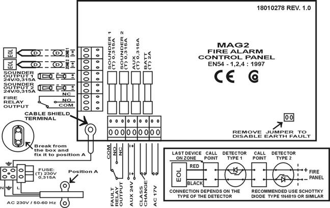
5 Department, return the P.C.B. CHASSIS ONLY to your supplier. DO NOT return the plastic box. Once the panel is found to operate satisfactorily in the NORMAL MODE, it is time to connect the external circuits. It has been assumed that prior to making the connection at the panel, the integrity of the system ALL wiring has been comprehensively tested, including insulation to earth. Isolate the mains supply and disconnect the battery connection. Fit the Active End of Line Device to the last detection device of zone one. Ensure all terminations are made correctly and all detector heads are plugged into their bases. Connect Detector circuit ONE to the panel terminal block. Power up the panel with the mains and battery. Press RESET button. The panel should be in the NORMAL MODE. NOTE: If General Fault and zone 1 FAULT LED s illuminate, there is a wiring / connection problem. Check the polarity of the connection, the connection of the devices and whether a head is removed. Check the EOL proper polarity and position. Operate ALL detection devices applicable to this zone, to ensure correct receipt of a fire signal and the correct operation of the panel controls. Refer to the User Instructions on the inside of the panel. Repeat the connection process for zone two as stated above. ENSURE the supply voltages are initially disconnected prior to each stage. ONCE THE CONNECTION OF THE ZONES ARE COMPLETED, CONNECT AND TEST ANY OF THE OTHER AUXILIARY CIRCUITS BEFORE CONNECTING THE EXTERNAL SOUNDER CIRCUITS. Relay Connection - The onboard relay volt free change over terminals are for low voltage use only. MAINS SUPPLY MUST NOT BE APPLIED TO THESE TERMINALS. Once the zone and auxiliary circuits have been connected and tested to function correctly, it is time to connect the first external sounder circuit: Isolate the mains supply and disconnect the battery connection. Remove the End of Line Monitoring Resistor from the terminal block of sounder circuit 1 (SND 1) and fit to the last sounder of circuit one. Check all sounder connections are made. Connect sounder circuit ONE to the panel terminal block. Apply mains and battery power. Press RESET The panel should be in the NORMAL MODE. Activate a zone Call Point. The sounders should operate. Press the reset button. Repeat the connection process for the second external sounder circuit, as stated above. ENSURE the supply voltages are initially disconnected prior to each stage. NOTE: If General Fault and SOUNDER FAULT / DISABLE LED. s illuminate, there is a wiring / connection problem. Check the polarity of the connection of each of the devices, the polarity of the connection of the devices to the Panel terminal block or whether an earth fault exists. 5
6 Engineers Facilities: To Disable Zone 1: Press RESET: To Enable Zone 1: Press ENABLE / DISABLE button TWICE: Press RESET. To Disable Zone 2: Press TEST / SCROLL button: Press RESET: To Enable Zone 2: Press TEST / SCROLL button: Press RESET: To One Man Test a Zone: Press TEST / SCROLL button: Zone 1 lamp will flash. DISABLE / ENABLE lamp will flash. The zone lamp will become steady. At this point the zone 1 is disabled. Zone 1 lamp will flash. DISABLE / ENABLE lamp will flash. At this point the zone 1 is disabled. Zone 1 lamp will flash. ENABLE / DISABLE lamp will flash. Zone 2 lamp will flash. ENABLE / DISABLE lamp will flash. Zone 2 lamp will become steady. ENABLE / DISABLE lamp will flash. At this point the zone 2 is disabled. Zone 1 lamp will flash. ENABLE / DISABLE lamp will flash. Zone 2 lamp will be steady. ENABLE / DISABLE lamp will flash. Zone 2 lamp will flash. ENABLE / DISABLE lamp will flash. At this point zone 2 is enabled. TEST AND ZONE yellow LED s will flash. Zone 1 is in Test Mode. Press TEST / SCROLL button: Flashing LED will move down to zone 2. Zone 2 is in Test Mode. The One Man Test Mode will exit when pressing the TEST / SCROLL button again, or at any time, by pressing RESET. 6
7 Disable Sounders: Press DISABLE / ENABLE button: Press TEST / SCROLL button again: Press TEST / SCROLL button once again: Press RESET: To enable Sounders: Press DISABLE / ENABLE button: Press TEST / SCROLL button: Press TEST / SCROLL button once again: Press RESET: DISABLE / ENABLE lamp will flash. Zone 1 lamp will flash. Zone 2 lamp will flash. SOUNDER FAULT / DISABLE lamp will flash. DISABLE / ENABLE lamp will flash. SOUNDER FAULT / DISABLE lamp changes to steady. ENABLE / DISABLE lamp flashes. At this point zone the sounders are disabled. DISABLE / ENABLE lamp will flash Zone 1 lamp will flash. Zone 2 lamp will flash. SOUNDER FAULT / DISABLE lamp will be steady. DISABLE / ENABLE lamp will flash. SOUNDER FAULT / DISABLE lamp change to flashing. ENABLE / DISABLE lamp flashes. At this point zone the panel has reset. Connecting The Additional Facilities Class Change: Connect a non latching switch to the class change terminals at the top of the MAINBOARD. Operation of the switch will cause the external sounders to pulse one second on followed by one second off. Once the panel connections and facilities have been functionally tested, replace and secure the front cover of the box, remembering to connect the earth bonding lead to the continuity terminal. 7
8 Specification Maximum number of detectors per zone Up to 32 conventional detectors and unlimited number of manual call points. Thresholds for zone conditions 0-2 ma Open circuit fault condition. 2-6 ma Normal condition ma Fire Alarm condition. 110 ma - Short circuit Short circuit condition. Power Supply Main Power supply 230V AC ± 10% 0.315A fuse Standby Power supply 1 x 12V Sealed Lead Acid Battery Up to 7Ah internally 2A fuse Maximum current available for system devices (with fully charged battery) 0.7 A Current consumption - mains failure 50 ma Outputs Sounder Circuit 1 24V / 0.315A 0.3A fuse Sounder Circuit 2 24V / 0.315A 0.3A fuse Fault Relay volt free changeover contacts 12V / 1A or 24V / 0.5A Max voltage 125V Max current 2A Auxiliary output 24V DC 0.3A fuse Cabling Maximum 2.5mm diameter Environment Working temperature 0 to 40 degrees C Storage temperature -20 to 60 degrees C Humidity 0 to 95% 8
9 Notes 9

10 Connection Circuit MAG 2 Connection Circuit MAG 4 10
11 Guarantee During the guarantee period the manufacturer shall, at its sole discretion, replace or repair any defective product when it is returned to the factory. All parts replaced and/or repaired shall be covered for the remainder of the original guarantee, or for ninety (90) days, whichever period is longer. The original purchaser shall immediately send manufacturer a written notice of the defective parts or workmanship, which written notice must in all cases be received prior to expiry of the guarantee. International Guarantee Foreign customers shall enjoy the same guarantee rights as those enjoyed by any customer in Bulgaria, except that manufacturer shall not be liable for any related customs duties, taxes or VAT, which may be payable. Guarantee Procedure This guarantee will be granted when the appliance in question is returned. The manufacturer shall accept no product whatsoever, of which no prior notice has been received. Conditions for waiving the guarantee This guarantee shall apply to defects in products resulting only from improper materials or workmanship, related to its normal use. It shall not cover: Damages resulting from transportation and handling; Damages caused by natural calamities, such as fire, floods, storms, earthquakes or lightning; Damages caused by incorrect voltage, accidental breakage or water; beyond the control of the manufacturer; Damages caused by unauthorized system incorporation, changes, modifications or surrounding objects: Damages caused by peripheral appliances (unless such peripheral appliances have been supplied by the manufacturer: Defects caused by inappropriate surrounding of installed products; Damages caused by failure to use the product for its normal purpose; Damages caused by improper maintenance; Damages resulting from any other cause, bad maintenance or product misuse. In the case of a reasonable number of unsuccessful attempts to repair the product, covered by this guarantee, the manufacturer s liability shall be limited to the replacement of the product as the sole compensation for breach of the guarantee. Under no circumstances shall the manufacturer be liable for any special, accidental or consequential damages, on the grounds of breach of guarantee, breach of agreement, negligence, or any other legal notion. Waiver This Guarantee shall contain the entire guarantee and shall be prevailing over any and all other guarantees, explicit or implicit (including any implicit guarantees on behalf of the dealer, or adaptability to specific purposes), and over any other responsibilities or liabilities on behalf of the manufacturer. The manufacturer does neither agree, nor empower, any person, acting on his own behalf, to modify or alter this Guarantee, nor to replace it with another guarantee, or another liability with regard to this product. Unwarranted Services The manufacturer shall repair or replace unwarranted products, which have been returned to its factory, at its sole discretion under the conditions below. The manufacturer shall accept no products for which no prior notice has been received. The products, which the manufacturer deems repairable, will be repaired and returned. The manufacturer has prepared a price list and those products, which can be repaired, shall be paid for every repaired appliance. The closest equivalent product, available at the time, shall replace the products manufacturer deems unrepairable. The current market price shall be charged for every replaced product. 11
12 Fire Alarm Record Installation Address: Contact Person:... Telephone:... Fax:... Date Completed:... Commissioned By:... Contract Reference:... Service Intervals: Monthly / Quarterly / Half Yearly / Annually ZONE LOCATION DETECTOR TYPE and SOUNDERS NUMBER QUANTITY PER ZONE Zone Quantity and Related Circuit Ion Ph RoR F/T C.P. Circuit 1 Circuit TOTALS: System Installed By: Telephone:... Fax:... 12
13 Service Record Date Zones Tested Faults Rectified Signature of Next Visit Completed Engineer Due Fire Alarm Event Log DATE TIME FIRE ZONE FAULT yes/no and TYPE ACTION TAKEN NAME yes/no number 13
14 E.S.P. Elite Security Products Unit 7 Leviss Trading Estate, Stechford, Birmingham B33 9AE Tel.: Fax: Distributed by: Rev.A 07/2004
LC1 & 2. Fire Alarm Panel 6\VWHPLQVWDOODWLRQRSHUDWLQJ PDLQWHQDQFH LQVWUXFWLRQV
 LC1 & 2 Fire Alarm Panel 6\VWHPLQVWDOODWLRQRSHUDWLQJ PDLQWHQDQFH LQVWUXFWLRQV ZIRCONLC1 One Zone Conventional Fire Panel ZIRCONLC2 Two Zone Conventional Fire Panel Compliant with EN54-2:1998 & EN54-4:1998
Sigma. K1000 Series 1, 2, 4 & 6 Zone Fire Control Panels. Operation and Maintenance Manual. Man-1048 Issue 05 October 2009
 Sigma K1000 Series 1, 2, 4 & 6 Zone Fire Control Panels Operation and Maintenance Manual Man-1048 Issue 05 October 2009 CONTENTS Contents... Page Safety & Installation...2 Installation - continued...3
Installation and user manual for the FX range of fire panels. 1, 2, 4 and 8 zone panels
 Installation and user manual for the FX range of fire panels 1, 2, 4 and 8 zone panels Contents Panel installation 3 Panel connections 3 Wiring connection drawings 4 Panel facilities 6 Installation check
FTEN1, FTEN2, & FTEN4 1, 2 & 4 ZONE FIRE DETECTION AND ALARM CONTROL PANELS
 QUICK USER GUIDE FOR, 2 & 4 ZONE PANELS INDICATORS COLOUR INDICATION MON FAULT Yellow On when a fault condition has occurred, or if no other fault Led is on, this indicates 24v auxiliary fuse failure.
Installation and user manual for the CF5000, MF5000 and FXP5000 range of fire panels
 CF5000, MF5000 and FXP5000 Installation and user manual for the CF5000, MF5000 and FXP5000 range of fire panels 16 zone panels Contents PANEL INSTALLATION...3 Installation...3 PANEL WIRING... 3 Mains power
INTELLIGENT FIRE TECHNOLOGY. Twinflex and Multipoint V3. User Guide (TO BE RETAINED BY USER) Issue 3
 Issue 3") INTELLIGENT FIRE TECHNOLOGY Twinflex and Multipoint V3 User Guide (TO BE RETAINED BY USER) 26-0340 Issue 3 Rafiki Protection Limited Rafiki policy is one of continual improvement and the right to change
INTELLIGENT FIRE TECHNOLOGY Twinflex and Multipoint V3 User Guide (TO BE RETAINED BY USER) 26-0340 Issue 3 Rafiki Protection Limited Rafiki policy is one of continual improvement and the right to change
Installation, Operating and Maintenance Manual
 STATUS ZONES CONTROLS FIRE FAULT DISABLED FIRE 1 2 3 4 5 6 7 8 TEST FAULT DISABLED 1 5 BUZZER SILENCE RESET 1 2 TEST 2 6 LAMP TEST 3 SUPPLY 3 7 SYSTEM FAULT 4 8 SOUNDERS ACTIVATE/ SILENCE 4 FAULTS INSTRUCTIONS
Operating manual and Log book for the range of 1,2,4 and 8 zone fire Control and Repeat panels
 Operating manual and Log book for the range of 1,2,4 and 8 zone fire Control and Repeat panels The panels are designed in accordance with the requirements of EN54 Part 2:1997 (and include optional clauses
PNC 1000 SERIES 2, 4, 8 Zone Fire Alarm Control Panel
 PNC 1000 SERIES 2, 4, 8 Zone Fire Alarm Control Panel INSTALLATION, OPERATION AND MAINTENANCE MANUAL Version: CN-PM-1000.VER1.1-12/2012 EN54 INFORMATION In accordance with EN 54-2 clause 13.7, the maximum
Intelligent Security & Fire Ltd
 OPERATIONAL NOTES FOR CONCEPT FIRE PANEL. NOTE ON NEW FIRE PANELS, POSITION 1 ON THE SIX WAY INTERNAL OPTION SWITCH IS TURNED ON, DISABLING THE ZONAL SOUNDERS. TO ENABLE ZONAL SOUNDERS TURN OFF. Operation
VoCALL - CFVCC5. Compact 5 Line Exchange Unit. Installation & Commissioning Manual
 VoCALL - CFVCC5 Compact 5 Line Exchange Unit Installation & Commissioning Manual Introduction A VoCALL Emergency Voice Communications System (EVCS) is a fixed, secure, bi-directional, full duplex voice
ANALOGUE ADDRESABLE FIRE PANEL
 ANALOGUE ADDRESABLE FIRE PANEL INSTALLATION MANUAL VERSION 1.0 Guarantee During the guarantee period the manufacturer shall, at its sole discretion, replace or repair any defective product when it is returned
Operating manual and Log book for the range of 1,2,4 and 8 zone fire Control and Repeat panels
 Operating manual and Log book for the range of 1,2,4 and 8 zone fire Control and Repeat panels The panels are designed in accordance with the requirements of EN54 Part 2:1997 (and include optional clauses
Saffire User & Installation Manual. IMPORTANT This manual should be left with the panel after installation.
 Saffire+ 8-12 User & Installation Manual IMPORTANT This manual should be left with the panel after installation. We reserve the right to change product specifications without prior notice. Copyright VRC
FEC400 Series. Installation Manual
 FEC400 Series Conventional microprocessor controlled fire detection and alarm panels with extinguishing control Installation Manual Version 2.3 / August 2004 Aritech is a GE Interlogix brand. http://www.geindustrial.com/ge-interlogix/emea
Control Panel User Guide
 Fire Detection & Alarm System Control Panel V4.14 Control Panel User Guide (TO BE RETAINED BY USER) 26-0397 Issue 6 Fike s policy is one of continual improvement and the right to change a specification
Logbook. Precept EN Fire Detection/Alarm Panel. & Precept EN Repeater
 APPROVED BY: JBJ Precept EN Fire Detection/Alarm Panel & Precept EN Repeater Logbook PAGE 1 of 19 List of Contents 1. FIRE ALARM SYSTEM MAINTENANCE... 3 2. USER RESPONSIBILITIES... 3 2.1. RESPONSIBLE PERSON...
NZ 400 AUTOMATIC FIRE ALARM SYSTEM OPERATORS MANUAL
 NZ 400 AUTOMATIC FIRE ALARM SYSTEM OPERATORS MANUAL Document No...G108WO1.DOC Serial No... Issue Date...17 th SEPTEMBER 1999 Software Version...1.4 APPROVED TO: NZS 4512:1997 AS/NZS 3548:1992 Fire Alarm
BT1 SINGLE ZONE FIRE ALARM SYSTEM OPERATORS MANUAL
 BT1 SINGLE ZONE FIRE ALARM SYSTEM OPERATORS MANUAL 26 Aug 2015 V1.8 Page 1 SECTION CONTENTS PAGE NO. 1.0 SYSTEMS DESCRIPTION 1.1 General descriptions 2 1.2 Master Alarm PCB 2 1.3 Zone Display Board 2 1.4
Control Panel Engineering and Commissioning Instructions
 Twinflex - V3 Fire Detection & Alarm System Control Panel Engineering and Commissioning Instructions (TO BE RETAINED BY THE COMMISSIONING ENGINEER) 26-0338 Issue 9 Fike s policy is one of continual improvement
Application, Installation, Operation & Maintenance Manual
 APPROVED BY:JBJ PRESCIENT III FIRE ALARM & GAS EXTINGUISHING CONTROL PANEL Application, Installation, Operation & Maintenance Manual PAGE 1 of 43 CONTENTS 1. INTRODUCTION... 3 2. GENERAL DESCRIPTION...
3500 CONVENTIONAL FIRE ALARM CONTROL PANEL
 3500 CONVENTIONAL FIRE ALARM CONTROL PANEL USER MANUAL Protec Fire Detection PLC, Protec House, Churchill Way, Nelson, Lancashire, BB9 6RT. Telephone: +44 (0) 1282 717171 Fax: +44 (0) 1282 717273 Web:
Operation and Maintenance Manual
 (FKER Series) Repeater Panel (FKER, FKER, FKER8) Operation and Maintenance Manual Man-9EL Issue June Index Section Page. Introduction.... Safety and mounting.... Technical specification.... Control panel
ANALOGUE ADDRESSABLE FIRE PANEL
 ANALOGUE ADDRESSABLE FIRE PANEL INSTALLATION AND PROGRAMMING MANUAL Contents 1. Introduction... 5 1.1 General Description... 5 1.2 General Specifications... 5 1.2.1 General Technical Specifications...6
3500 CONVENTIONAL FIRE ALARM CONTROL PANEL
 3500 CONVENTIONAL FIRE ALARM CONTROL PANEL INSTALLATION AND COMMISSIONING MANUAL Protec Fire Detection PLC, Protec House, Churchill Way, Nelson, Lancashire, BB9 6RT. Telephone: +44 (0) 1282 717171 Fax:
6100 SINGLE LOOP DIGITAL ADDRESSABLE FIRE ALARM CONTROL PANEL
 6100 SINGLE LOOP DIGITAL ADDRESSABLE FIRE ALARM CONTROL PANEL USER MANUAL Protec Fire Detection plc, Protec House, Churchill Way, Nelson, Lancashire, BB9 6RT. Telephone: +44 (0) 1282 717171 Fax: +44 (0)
USER MANUAL COMBINED FIRE & EXTINGUISHING CONTROL PANEL COMPLIES WITH BS EN PART 1 & EN54 PARTS 2 & 4
 PREMIER EX8 EXTINGUISHING PANEL USER MANUAL COMBINED FIRE & EXTINGUISHING CONTROL PANEL COMPLIES WITH BS EN 12094 PART 1 & EN54 PARTS 2 & 4 USER MANUAL Approved Document No: GLT.MAN-132 INDEX Extinguishing
SYSTEM MANUAL FT1-SB. Single Zone Fire Alarm System
 SYSTEM MANUAL FT1-SB Single Zone Fire Alarm System DOCUMENT HISTORY Issue Date Description Written By Checked By Draft 0 2/9/2008 Original Document. A. Shenouda C. Orr Issue 1 4/11/2011 Update drawing
USER MANUAL & MAINTENANCE GUIDE OG OO
 M+48. USER MANUAL & MAINTENANCE GUIDE OG OO What to do if the Fire Alarm Panel shows an Alarm (Red LED) Write down which LEDs are lit (either in the log book, or on a piece of paper for transferring to
3200 NON-ADDRESSABLE FIRE ALARM CONTROL PANEL
 3200 NON-ADDRESSABLE FIRE ALARM CONTROL PANEL USER MANUAL Protec Fire Detection PLC, Protec House, Churchill Way, Nelson, Lancashire, BB9 6RT. Telephone: +44 (0) 1282 717171 Fax: +44 (0) 1282 717273 Web:
User Operation Manual
 APPROVED BY: JBJ PRESCIENT III FIRE ALARM & GAS EXTINGUISHING CONTROL PANEL User Operation Manual PAGE 1 of 6 1 CONTENTS 1. FIRE - GENERAL... 3 2. FIRE - ZONES 1 OR 2 - AUTOMATIC MODE... 3 3. FIRE - ZONES
BiWire Flexi. BiWire Flexi Fire Panel EFBW8ZONE-FLEXI / EFBW4ZONE-FLEXI / EFBW2ZONEFLEXI Installation Manual
 BiWire Flexi BiWire Flexi Fire Panel EFBW8ZONE-FLEXI / EFBW4ZONE-FLEXI / EFBW2ZONEFLEXI Installation Manual Contents Contents 1. INTRODUCTION... 4 1.1 Purpose...4 2. THE BIWIRE FLEXI FIRE DETECTION & ALARM
Precept Marine Control Panel Application Guide
 Precept Marine Control Panel Application Guide Contents Page 1.0 Cabinet Specifications 2 2.0 Panel Hardware Specifications 5 3.0 Panel Configuration 8 4.0 Technical Specifications 8 5.0 Battery Sizes
Installation and user manual for the BiWire / Conventional Repeater Panel
 Panel EFBWCV-REPEATER Contents Introduction.... 3 Purpose... 3 The Panel.... 3 Indication Equipment (IE).... 3 Power Supply Equipment (PSE).... 4 System Wiring.... 5 Status Indications.... 5 Repeater I/O....
FIRE ALARM CONTROL PANEL FVC01-08
 FIRE ALARM CONTROL PANEL FVC01-08 USER MANUAL, MAINTENANCE GUIDE & LOG BOOK Radal Technology Limited Unit 1, Webber Court Billington Road, Burnley Lancashire, BB11 5UB Tel: +44 (0) 1282 463 770 Fax: +44
Maintenance Manual PC6010. WARNING This manual contains information on limitations regarding product use and function
 WARNING This manual contains information on limitations regarding product use and function and information on the limitations as to liability of the manufacturer. The entire manual should be carefully
FEC403EN Installation Manual
 FEC403EN Installation Manual P/N 10-4101-501-2FC1-01 ISS 22JAN15 Copyright Trademarks and patents Manufacturer 2015 UTC Fire & Security. All rights reserved. The FEC403EN name and logo are trademarks of
PAT E N T System 88. COMPLIES WITH Singapore Standard : SS CP10 : 2005 British Standard : BS EN54-2 : 1998 BS EN54-4 : 1998 REV.00
 PAT E N T System 88 COMPLIES WITH Singapore Standard : SS CP10 : 2005 British Standard : BS EN54-2 : 1998 BS EN54-4 : 1998 REV.00 Pg 1 of 12 CONTENTS 1. GENERAL 1.1 Introduction 2 1.2 System Description
RAM-208. Remote Multiplex Annunciator Panel. Wiring & Installation Installation Manual COMMON TROUBLE A.C. ON SIGNAL SILENCED BUZZER SILENCE
 Advanced Life Safety Solutions RAM-208 Remote Multiplex Annunciator Panel A.C. ON COMMON TROUBLE SIGNAL SILENCED BUZZER SILENCE SIGNAL SILENCE LAMP TEST SYSTEM RESET Wiring & Installation Installation
FW-RA-LED Remote Multiplex Annunciator Panels
 FW-RA-LED Remote Multiplex Annunciator Panels WIRING and INSTALLATION INSTRUCTION LNOTICE All information, documentation, and specifications contained in this manual are subject to change without prior
ZX1e ZX2e ZX5e. Document No Issue 01 user manual
 ZX1e ZX2e ZX5e Document No. 996-130 Issue 01 user manual MORLEY-IAS ZX2E/ZX5E Fire Alarm Control Panels Table of Contents 1 INTRODUCTION... 4 1.1 NOTICE... 4 1.2 WARNINGS AND CAUTIONS... 4 1.3 NATIONAL
CONVENTIONAL CONTROL PANEL FL2/4/8/12 LT-XP
 FLx-LT-XP CONVENTIONAL CONTROL PANEL FL2/4/8/12 LT-XP Installation, Configuration and Operating Manual MAY 2008 MIE-MI-580I_FL rev.003 Information in this document is subject to change without notice.
Quick Reference Guide
 WARNING This manual contains information on limitations regarding product use and function and information on the limitations as to liability of the manufacturer. The entire manual should be carefully
Alarm Control Panel CA62
 Alarm Control Panel CA62 Installation and Programming Manual WARNING This manual contains information on limitations regarding product use and function and information on the limitations as to liability
Syncro AS. Analogue Addressable Fire Control Panel. User Manual
 Syncro AS Analogue Addressable Fire Control Panel User Manual Man-1100 Issue 02 Nov. 2008 Index Section Page 1. Introduction...3 2. Safety...3 3. Panel Controls...4 3.1 Access Level 1...4 3.2 Access Level
FIREPRO INSTALLATION MANUAL FIRE ALARM CONTROL PANEL INSTALLATION MANUAL. Approved Document No. GLT Issue: 1. 8 Author: NRPJ Date: 7/ 3/201 4
 FIRE ALARM CONTROL PANEL INSTALLATION MANUAL Approved Document No. GLT -201-7-3 Issue: 1. 8 Author: NRPJ Date: 7/ 3/201 4 CONTENTS 1. INTRODUCTION... 1.1 HANDLING THE PCBS... 1.2 USING THIS MANUAL... 1.3
OPERATION & INSTALLATION MANUAL FOR ALARM PANEL M2AP01
 OPERATION & INSTALLATION MANUAL FOR ALARM PANEL M2AP01 Table of Contents Safety Instructions 4 Owner/Operator Responsibility 4 Specifications 5 Introduction 6 Installation Instructions 7 Setup 7 Wiring
Networked Access Control Panel. Installation Guide
 XP2M Networked Access Control Panel V1.0X Installation Guide X P 2 M A C C E S S C O N T R O L S Y S T E M Installation Guide Document Ref: PLAN XP2M Installation Guide V4(G)2010 Access Control Services
OPERATION AND INSTALLATION MANUAL
 EX+Plus 2 ZONE, 1AREA EXTINGUISHANT CONTROL PANEL OPERATION AND INSTALLATION MANUAL INTRODUCTION The Premier EX Plus is a 2 zone, single area panel for controlling the release of extinguishing gases in
RAX-LCD-LITE. Remote Annunciator. Installation and Operation Manual
 RAX-LCD-LITE Remote Annunciator Installation and Operation Manual LT-1149 Rev.1 July 2014 Table of Contents 1.0 Introduction 6 2.0 Mechanical Installation 8 2.1 Mounting Dimensions... 8 3.0 Wiring Instructions
Intelligent Security & Fire Ltd
 full installation, commissioning and operating manuals can be downloaded from www.haes-systems.co.uk combined addressable / conventional fire alarm control panel User Guide Approved Document No. MFBU-04
Intelligent Security & Fire Ltd
 Sigma CP (K and T Series) and Sigma CP-A Conventional Fire Control Panel (K11020M2, K11040M2, K11080M2) (T11020M2, T11040M2, T11080M2) (KA11020M2, KA11040M2, KA11080M2) User Manual Man-1082 Issue 05 August
Conventional Fire Alarm System 2014 V1.2
 Conventional Fire Alarm System 2014 V1.2 Product Overview Control Panel 2 Conventional Fire Panel GST102A 2 zone Fire panel GST104A 4 zone Fire panel GST108A 8 zone Fire panel GST116A 16 zone Fire Panel
Menvier Fire System MF9300
 Menvier Fire System MF9300 Eight and sixteen zone control panels Installation and User Instructions and Systems Log IMPORTANT THIS MENVIER FIRE PANEL IS DESIGNED TO BE USED WITH POLARISED AND SUPPRESSED
FIREBETA EXTINGUISHING CONTROL PANEL (ECP)
") F I R E D E T E C T I O N A N D C O N T R O L FIREBETA EXTINGUISHING CONTROL PANEL (ECP) Three versions: 2 areas of detection and 1 area extinguishing 4 areas of detection and 1 area extinguishing 4 areas
F I R E D E T E C T I O N A N D C O N T R O L FIREBETA EXTINGUISHING CONTROL PANEL (ECP) Three versions: 2 areas of detection and 1 area extinguishing 4 areas of detection and 1 area extinguishing 4 areas
MR-2316-AT/Z Remote Annunciator
 MR-2316-AT/Z Remote Annunciator Secutron LT-617SEC Rev.1 February 2011 Table of Contents Table of Contents 1.0 Introduction 7 1.1 Contact Us... 7 1.1.1 General Inquiries... 7 1.1.2 Customer Service...
Smoke Vent Control Panel PCB4 V4 Installation Manual
 Smoke Vent Control Panel PCB4 V4 Installation Manual 10A PCB4 Control Panel Do Not Remove From PCB4 Control Panel www.besafedirect.com Page 1 Contents Page 3) Important Regulations, Safety, Maintenance,
Conventional Fire Control Panel (FKEP2, FKEP4, FKEP8) Operation and Maintenance Manual. Man-1078EL Issue 01 February 2014
 Operation and Maintenance Manual. Man-1078EL Issue 01 February 2014") Conventional Fire Control Panel (FKEP2, FKEP4, FKEP8) Operation and Maintenance Manual Man-1078EL Issue 01 February 2014 B Index Page 1. Introduction... 3 1B2. Safety and mounting... 3 2B3. Technical specification...
Conventional Fire Control Panel (FKEP2, FKEP4, FKEP8) Operation and Maintenance Manual Man-1078EL Issue 01 February 2014 B Index Page 1. Introduction... 3 1B2. Safety and mounting... 3 2B3. Technical specification...
Hydrosense. Vimpex Limited. Star Lane. Great Wakering. Essex SS3 0PJ. Tel: +44 (0) Fax +44 (0)
 Fax +44 (0)") Overview of the Water Detection System 2 Components of a System 4 Design & Planning 5 System Installation Notes 7 Control Panel Installation - HSCPI-K3000 8 Control Panel Commissioning HSCPC-K3000 11 Front
Overview of the Water Detection System 2 Components of a System 4 Design & Planning 5 System Installation Notes 7 Control Panel Installation - HSCPI-K3000 8 Control Panel Commissioning HSCPC-K3000 11 Front
Installation and Operating Instructions
 Twinflex and Multipoint Installation and Operating Instructions Rafiki Protection Limited 55 Springvale Industrial Estate Cwmbran South Wales NP44 5BD United Kingdom Tel. (+44) 01633 865558 Fax (+44) 01633
RAM-216. Remote Multiplex Annunciator Panel. Wiring & Installation Manual COMMON TROUBLE A.C. ON SIGNAL SILENCED BUZZER SILENCE SIGNAL SILENCE
 Advanced Life Safety Solutions RAM-216 Remote Multiplex Annunciator Panel A.C. ON COMMON TROUBLE SIGNAL SILENCED BUZZER SILENCE SIGNAL SILENCE LAMP TEST SYSTEM RESET Wiring & Installation Manual LT-658
NFS Supra / VSN-2Plus / ESS-2Plus Conventional Fire Alarm Control Panel. Installation and Operating Manual
 / VSN-2Plus / ESS-2Plus Conventional Fire Alarm Control Panel Installation and Operating Manual HLSI-MN-025-I v.05 April 2015 Note: This manual is valid for the following control panel models: NFS-Supra
Installation Manual CFP-105. Fire Alarm Control Panel. Version 1.0
 CFP-105 Fire Alarm Control Panel Installation Manual Version 1.0 WARNING: This manual contains information on limitations regarding product use and function and information on the limitations as to liability
SIMPLICITY CO CARBON MONOXIDE DETECTION & VENTILATION PANEL
 SIMPLICITY CO CARBON MONOXIDE DETECTION & VENTILATION PANEL USER MANUAL 1 Table of Contents 1 SAFETY INFORMATION...3 1.1 SAFETY PRECAUTIONS DURING NORMAL OPERATION OF PANEL...3 1.3 BATTERY INFORMATION...3
Excel-EN Conventional Fire Control Panel
 Available as 2, 4, 6, 8,10 or 12 zones Approved to EN54-2 & 4 Modular expansion zone cards Programmable relays and outputs Optional additional sounder circuits Optional additional programmable outputs
MR-2602 Two Zone Fire Alarm Control Panel
 MR-2602 Two Zone Fire Alarm Control Panel Installation Manual Secutron LT-2015 Rev.3 July 2010 Table of Contents 1 Introduction 1.1 The MR-2602 Fire Alarm Control Unit... 11 1.1.1 General features...
Matrix2000. User Guide - CPD Advanced Analog Fire Alarm Control Panel 4 24 Zones. Version: 2.0 Revision: 1
 Matrix2000 User Guide - CPD Advanced Analog Fire Alarm Control Panel 4 24 s Version: 2.0 Revision: 1 IMPORTANT INFORMATION Limitation of liability It is mandatory, Matrix2000 panel to be installed in accordance
Sentry LIQUID LEVEL CONTROLLER MODEL 120 OPERATING MANUAL.
 Sentry LIQUID LEVEL CONTROLLER MODEL 120 OPERATING MANUAL www.aquaticsentry.com TABLE OF CONTENTS 1. SAFETY PRECAUTIONS... 3 2. APPLICATION... 3 2.1 HIGH AND LOW LEVEL ALARM 2.2 PUMP DOWN CONTROLLER 2.3
highline SVCS-1 INSTALLATION & USER MANUAL SMOKE VENT CONTROL SYSTEM * enclosure design may vary software version: SVCS1r6 SVCS1r7 SVCS1r10
 highline WINDOW CONTROLS INSTALLATION & USER MANUAL SMOKE VENT CONTROL SYSTEM SVCS-1 * enclosure design may vary software version: SVCS1r6 SVCS1r7 SVCS1r10 CERTIFICATE OF COMPLIANCE SVCS-1 We the undersigned
5000 INSTALLATION GUIDE
 5000 INSTALLATION GUIDE Table of Contents Section Page No 1. INTRODUCTION... 3 2. WARNINGS AND CAUTIONS... 3 3. UNPACKING... 3 4. INSTALLATION... 4 5. CONTROL PANEL - REMOVING ITEMS BEFORE MOUNTING...
Door Release Power Supply
 www.protectingpeople.co.uk Door Release Power Supply Engineer / Installation Manual Document: VI55.1 Protecting People Printed : 04/03/2004-1 - Ventcroft Ltd Door Release Power Supply Engineer / Installation
KFP-CF Series Operation Manual
 KFP-CF Series Operation Manual P/N 501-415103-2-31 REV 03.10 ISS 13NOV13 Copyright Trademarks and patents Manufacturer Version Certification European Union directives Contact information 2013 UTC Fire
Fire Alarm Control Panel. System Maintenance and Log Book
 Fire Alarm Control Panel System Maintenance and Log Book Fire Alarm System Maintenance A fire alarm system must provide early and reliable warning of the outbreak of fire. To achieve this, the system remains
USER MANUAL, MAINTENANCE GUIDE & LOG BOOK
 ONE OR TWO LOOP ANALOGUE ADDRESSABLE FIRE ALARM CONTROL PANEL USER MANUAL, MAINTENANCE GUIDE & LOG BOOK Approved Document No: GLT.MAN-108 TABLE OF CONTENTS WHAT TO DO IF THE FIRE ALARM PANEL SHOWS AN ALARM
Operating manual and Log book for the range of 1,2,4 and 8 zone fire Control and Repeat panels
 Operating manual and Log book for the range of 1,2,4 and 8 zone fire Control and Repeat panels The panels are designed in accordance with the requirements of EN54 Part 2:1997 (and include optional clauses
RAM-3500-LCD. Remote Annunciator. Installation and Operation Manual
 RAM-5-LCD Remote Annunciator Installation and Operation Manual LT-9 Rev. July Table of Contents. Introduction 6. Contact Us... 6. Mechanical Installation 8. Mounting Dimensions... 8. Configuring the Main
INSTALLATION MANUAL PC56O. Version 1.OA
 INSTALLATION MANUAL PC56O Version 1.OA TABLE OF CONTENTS INTRODUCTION 3 Features... 3 Specifications... 3 INSTALLATION 4 Mounting the Control Panel... 4 Mounting the Keypad... 4 Wiring... 5 Burglary Zone
ZSC100 Gas Detection and Alarm System Controller
 ZSC100 Gas Detection and Alarm System Controller User Guide 1- Introduction... 3 1.1- General description... 3 1.2- Cautions and warnings... 3 2- Control panel... 4 2.1 Control panel overview... 4 2.2
1 measurement signal input 4-20 ma for connection to an external gas sensor 5 freely programmable alarm switching points per measuring point
 Medium - Control - System Franke & Haqenest GmbH Borngasse 1a * 04600 Altenburg Tel: 03447-499 313-0 Fax: 03447-499 313-6 email: info@mcs-gaswarnanlagen.de MCS User Guide MCS GasController Microprocessor
Unity DAU Voice Alarm System
 Unity DAU Voice Alarm System User Manual & Log Book Site Name Address Contractor Commissioned Introduction Voice Alarm (VA) systems are the quickest way to evacuate the public & staff from a building.
Control Panel User Guide (TO BE RETAINED BY THE USER)
") Fire Detection & Alarm System Control Panel V3 (Suitable for Quadnet control panels from V2.00) Control Panel User Guide (TO BE RETAINED BY THE USER) 26-0585 Issue 7 Fike s policy is one of continual improvement
Fire Detection & Alarm System Control Panel V3 (Suitable for Quadnet control panels from V2.00) Control Panel User Guide (TO BE RETAINED BY THE USER) 26-0585 Issue 7 Fike s policy is one of continual improvement
1200-HCM DIN RAIL MOUNTING FIRE SYSTEM MODULE Fire Detection & Extinguishant Control A R T PATOL LIMITED SUPPLY FAULT SOUNDER
 Application The unit is primarily intended for use where there is a requirement to integrate a limited fire protection function into a larger control equipment scheme, or in specialist applications where
INDEX 1- Introduction The Control Pane...7l 4.1- The Control Panel 1 and 2 Loops The Control Panel 4 and 8 Loops...
 GUIDE MANUAL INDEX 1- Introduction...5...5...6 4- The Control Pane...7l 4.1- The Control Panel 1 and 2 Loops...7 4.2- The Control Panel 4 and 8 Loops...9 5- Installation Guide...10 5.1- Pre-Installation
USER MANUAL, MAINTENANCE GUIDE & LOG BOOK
 ONE TO FOUR LOOPS ANALOGUE ADDRESSABLE FIRE ALARM PANEL USER MANUAL, MAINTENANCE GUIDE & LOG BOOK Page 1 TABLE OF CONTENTS WHAT TO DO IF THE FIRE ALARM PANEL SHOWS AN ALARM (RED LED)... 4 WHAT TO DO IF
FSTP4-2-wire 4 Zone Conventional Fire Control Panel Operation and Maintenance Manual. Man-1078FS4 Issue 01 April 2012
 FSTP4-2-wire 4 Zone Conventional Fire Control Panel Operation and Maintenance Manual Man-1078FS4 Issue 01 April 2012 Index Page 1. Introduction... 3 2. Safety and mounting... 3 3. Technical specification...
SOLO Single Loop Addressable Fire Control Panel
 Solo Single Loop Analogue Addressable Fire Control Panel Apollo Protocol Installation, Commissioning & Operating Manual Issue 03 June 1999 CONTENTS Section... Page 1. Introduction...1 2. Safety...2 3.
TESTSAFE. minipat APPLIANCE TESTER USER MANUAL
 TESTSAFE minipat APPLIANCE TESTER USER MANUAL TABLE OF CONTENTS SAFETY RULES 3 GENERAL DESCRIPTION 4-9 Overall Result 4 Earthing and Class I Appliances 5 Overall Result Class I Appliances and Cables 5
TECHNICAL DATA. Humidity: 85% Relative Humidity (non-condensing) at 90 F (32 C) maximum.
 at 90 F (32 C) maximum.") September 29, 1997 Firecycle III 433 a 1. PRODUCT NAME VIKING Model E-1 Manufactured 1997 Present 2. MANUFACTURED FOR THE VIKING CORPORATION 210 N Industrial Park Road Hastings, Michigan 49058, U.S.A.
September 29, 1997 Firecycle III 433 a 1. PRODUCT NAME VIKING Model E-1 Manufactured 1997 Present 2. MANUFACTURED FOR THE VIKING CORPORATION 210 N Industrial Park Road Hastings, Michigan 49058, U.S.A.
Panel Functions & Indicators - Key to Icons General & Zone Fire LEDs ACCEPT SOUNDERS START/ STOP RESET BUZZER MUTE KEYSWITCH DELAY ON/OFF ITEM SELECT
 Islenska Français Deutsch Nederlands Svenska EN54-8 Zone Conventional Fire Control Panel User Manual 997-493-00, Issue 0 November 003 Panel Functions & Indicators - Key to Icons General & Zone Fire LEDs
CONTENTS. GST102A/104A/108A/116A Conventional Fire Alarm Control Panel Installation and Operation Manual
 CONTENTS Installation Precautions... 1 EN 54 Information... 2 Chapter 1 Product Overview... 3 1.1 Features... 3 1.2 Technical Specifications... 3 1.2.1 Operating Voltage... 3 1.2.2 Batteries... 3 1.2.3
Control Panel User Guide
 Fire Detection & Alarm System Control Panel (Suitable for TWINFLEX pro control panels from V1.00) Control Panel User Guide (TO BE RETAINED BY THE USER) 26-1028 Issue 2 Fike s policy is one of continual
HA-263K HA-263D. OWNER'S MANUAL Installation And Operation 8-ZONE ALARM CONTROL PANEL FOR HOME AND OFFICE PROTECTIONS OPEN THE CABINET FOR SERVICE
 D (OPERATION) INITIATE A DYNAMIC BATTERY TEST The system tests the back-up battery once every 24 hours. The owner can initiate a dynamic battery test at any time with the following codes while the system
GAS SUPRESSION CONTROL PANEL:
 GAS SUPRESSION CONTROL PANEL: MODEL NAME: COMPANY: DELTA 437/2, Main Road, Mandwali Fazalpur, Delhi-110092 Page 1 ABOUT THE PRODUCT ASES is very proud of to introduce DELTA the completely digital microprocessor
SMART EVO 2 - User Manual ELECTRICAL PANEL FOR 2 MOTORS
 SMART EVO 2 - User Manual ELECTRICAL PANEL FOR 2 MOTORS CONTENTS 1. INTRODUCTION... 5 2. WARNINGS... 6 3. GENERAL DESCRIPTION... 7 4. INSTALLATION... 8 5. LUMINOUS INDICATORS AND COMMANDS... 9 6. DIP-SWITCH
EX8. Instruction Manual: COMBINED FIRE & EXTINGUISHING CONTROL PANEL COMPLIES WITH BS EN PART 1 AND EN54 PARTS 2 & 4
 EX8 COMBINED FIRE & EXTINGUISHING CONTROL PANEL COMPLIES WITH BS EN 12094 PART 1 AND EN54 PARTS 2 & 4 Instruction Manual: Approved Document No: GLT.MAN-124 PAGE 2 INDEX INDEX... 3 Introduction... 4 Indications
VX SERIES Wireless Thermostat with Occupancy Sensor
 VX SERIES Wireless Thermostat with Occupancy Sensor INSTRUCTION MANUAL Table of Contents Thermostat Installation... 7 Installing the Wireless Control Card...8 Mounting the thermostat to the wall...9 Thermostat
PROFYRE C8 USER MANUAL, MAINTENANCE GUIDE & LOG BOOK FIRE ALARM CONTROL PANEL USER MANUAL, MAINTENANCE GUIDE & LOG BOOK
 FIRE ALARM CONTROL PANEL USER MANUAL, MAINTENANCE GUIDE & LOG BOOK Approved Document No: EF-PFC8UM-1 Contents 1. FIRE ALARM CONTROL PANEL SAFETY ISSUES... 2 2. THE PURPOSE OF A FIRE ALARM SYSTEM... 2 3.
DTS SECURITY P.O.BOX 3399 Base plate-mounting EDENVALE instructions 1610 TELEPHONE
 DTS Megashock 5 Energizer 5J (Indoor installation) INSTALLATION MANUAL Comply to: SANS IEC 60 335-2-76 NRCS Ref. no. 7357 10 14 DTS SECURITY P.O.BOX 3399 Base plate-mounting EDENVALE instructions 1610
Conventional Fire Control Panel
 (FKEW Series) Conventional Fire Control Panel (FKEW2, FKEW4, FKEW8) Man-1138EL Issue 01 February 2014 Contents 1. Introduction... 4 2. Safety... 4 4. Technical specification... 5 5. Control panel fascia...
ELECTRIC FIRE PUMP CONTROLLER
 ELECTRIC FIRE PUMP CONTROLLER INSTRUCTION MANUAL CONTENTS 1. INTRODUCTION 1.1 Safety 1.2 Warranty 1.3 Safety Precautions 1.4 Product Overview 1.5 AS2941-2008 Requirements 2. FEATURES 3. FUNCTIONS AND OPERATIONS