SERIES 32C TEMPERATURE/PROCESS CONTROLLER. Instruction Manual
|
|
|
- Darcy Caldwell
- 5 years ago
- Views:
Transcription

1 SERIES 32C TEMPERATURE/PROCESS CONTROLLER Instruction Manual
2 Introduction Congratulations on your purchase of an Athena Series 32C Temperature/Process Controller. It is designed for ease of use and reliability wherever accurate control is required. After following the instructions for installation, simply step through and set your operating parameters using the controller s easy menu system. The instrument may then be automatically or manually tuned to your process for optimum setpoint control. A Qick-Start Reference Card is in the back of the instruction manual for experianced users of PID controllers. As you look through this manual, you will notice italizised text appearing in the margins and adjacent to operating information. These notes impart important information about the controller and may answer questions you may have about its setup or operation. If you still have questions or require any assistance, please contact your Athena representative or call technical support at Outside the U.S., please call Precautions After unpacking, inspect the instrument for any physical damage that may have occured in shipping. Save all packing materials and report any damage to the carrier immediatley. 1 Copyright 1999, Athena Controls, Inc.
3 Features Safety Warning Field-Selectable Thermocouple, RTD, or Voltage Input Current Input (with External 2.5 Ohm Resistor) On/Off Through Full PID Operation Autotuning - Heat or Cool Adjustable On/Off Output Hysteresis Dual Outputs Field-Configurable Process or Deviation Alarms Output % or Process Value Display Bumpless, Auto-Manual Transfer NEMA 4X Front Bezel 4-Digit (0.40") Alphanumeric Display Approvals: UL, cul, CE-compliant In addition to presenting a potential fire hazard, high voltage and high temperature can damage equipment and cause severe injury or death. When installing or using this instrument, follow all instructions carefully and use approved safety controls. Electrical connections and wiring should be performed only by suitably trained personnel. Do not locate this instrument where it is subject to excessive shock, vibration, dirt, moisture, oil, or other liquids. The safe operating temperature range for this unit is 32 F to 140 F (0 C to 60 C). 2
4 Table of Contents Installation 4 Dimensions and Mounting 4 Wiring 5 Output Types 8 Operation 9 Front Panel Controls 9 Power On 9 Security Levels 10 Menu System 11 Initial Setup Sequence 15 Menus and Parameters 16 Operating Modes 22 Alarms 23 Available Control Methods 24 Autotuning 25 Manual Tuning 26 Error Codes 27 Technical Specifications 28 Ordering Code 30 Recalibration Procedures 31 Quick Helps 32 Warranty/Repairs 35 Quick Setup Instructions 37 3

5 Installation Measurements between centerlines of panel cutouts are minimum recommended. Unpacking and Inspection 1. Inspect shipping carton for obvious signs of mishandling. 2. After removing the controller from the shipping carton, inspect it carefully for damage. Never attempt to install and use a damaged unit. 3. Verify that the ordering code number indicated on the side of the controller matches what was ordered. Figure 1. Recommended Panel Layout for Multiple Controllers C L 2.10" (53.34 mm) C L C L 1.50" (38.10 mm) C L Dimensions Figure 2. Case Dimensions 1.890" (48 mm) 1.772" (45 mm).944" (23.97mm).874" (22.19 mm) Cutout.328" (8.33 mm) 3.937" (99.99 mm) Side View.870" (22.09 mm) Prior to mounting the Series 32C in your panel, make sure that the cutout opening is of the right size, 0.874" x 1.772" (22.19 mm x 45.0 mm), and deburred to enable a smooth fit. A minimum of 4.5" (113 mm) of depth behind the panel is required. 4
6 Mounting Figure 3. Mounting Diagram Insert the Series 32C through the front panel cutout and slide the mounting collar back onto the unit from behind the panel. Push the mounting collar up tight to the back of the mounting panel. Bezel Gray Gasket Mounting Collar Side View Black Gasket (Bevel faces user) Customer Panel Wiring IMPORTANT: All electrical wiring connections should be made only by trained personnel, and in strict accordance with the National Electrical Code and local regulations. The Series 32C controller has built-in circuitry to reduce the effects of electrical noise (RFI) from various sources. However, power and signal wires should always be kept separate. We recommend separating connecting wires into bundles: power; signal; alarms; and outputs. These bundles should then be routed through individual conduits. Shielded sensor cables should always be terminated at one end only. If additional RFI attenuation is required, noise suppression devices such as an R.C. snubber at the external noise source may be used. If you wish, you may order this suppressor directly from Athena. Figure 4. Contact Identification Output Output Ω + - T/C RTD Voltage (current) L2 L V 50/60 Hz
7 Wiring Thermocouple circuit resistance should not exceed 100 ohms for rated accuracy; errors will occur at higher resistance values. If shielded thermocouple wire is used, terminate the shield only at one end. When using an RTD sensor, an approximate error of 6 F (3.3 C) will result for each ohm of resistance encountered in the lead wires. If shielded RTD wire is used, terminate the shield only at one end. The Series 32C accepts Type J, K, or T thermocouples, 100 ohm RTDs and linear inputs (suppressed or unsuppressed). It is shipped from the factory set for thermocouple or linear input; however, a shunt jumper is located on the PC board near the rear of the unit. This jumper (JMP01) is accessible by removing the back portion of the case. It is not necessary to remove the PC board from the case. See table below. Thermocouple Input Wiring Using the appropriate thermocouple and extension wire, connect the negative lead (generally colored red in ISA-type thermocouples) to contact 2; connect the positive lead to contact 1. Extension wires must be the same polarity as the thermocouple. RTD Wiring Connect 2-wire, 100 ohm platinum RTD to contacts 1 and 2. Keep leads short and use copper extension wire Figure 5. Thermocouple, RTD, and Voltage Connections 6
8 Wiring Process and Linear Input Wiring Voltage Inputs: Connect the positive voltage input to contact 1 and the negative to contact 2 (Figure 5). Current Inputs: (Figure 6) Connect the positive current input to contact 1 and the negative current input to contact (2.5Ω) Connect an external 2.5 ohm shunt resistor across the contacts. + - Figure 6. Current Input Wiring The Series 32C accepts both 85 to 265 Vac and 120 to 375 Vdc line power without any switch settings or polarity considerations. All connections should be made in accordance with the National Electrical Code and local regulations, using only NEC Class 1 wiring for all power terminals. Both of the incoming power lines should be fused with 2AG, 0.5 amp maximum rated fuses. Be sure that only instrument power input is fused not power to the load. 7 8 L2 L1 Figure 7. Power Wiring Connection 7
9 Output Types The Type R output is a mechanical device and subject to wear. To extend the life of the relay, set the Cycle Time for the relay output to the longest duration that still affords good control. When you ordered your Series 32C controller, a specific output device combination was specified. See page 40 for the ordering code, and compare it to the part number on the controller label. Your controller was also configured at the factory with either one or two output actions. Generally, output 1 is used as a reverse-acting (heat) function and output 2 is a direct-acting (cool) function. However, the Series 32C provides the option of having either or both outputs configured as reverse or direct acting. For best results, follow the recommendations given below for setting cycle times. A brief description of output devices follows on the next page. For Control Output Type Select Cycle Time (in seconds) B (Output 1 Only) 15 S 0 Output #1 B S T 15 Electromechanical relay, 120/240 Vac, normally open, used for switching resistive loads. DC logic 5Vdc pulsed T* Solid-state relay, zero voltageswitched and optically isolated from drive signal. Resistive loads to 120/240 Vac may be controlled using an external contactor. Larger loads may be controlled using an external con tactor. Output #2 S* DC logic 5Vdc pulsed T Solid-state relay, zero voltageswitched and optically isolated from drive signal. Resistive loads to 120/240 Vac may be controlled using an external contactor. Larger loads may be controlled using an external con tactor. *Output combination TS is not available 8

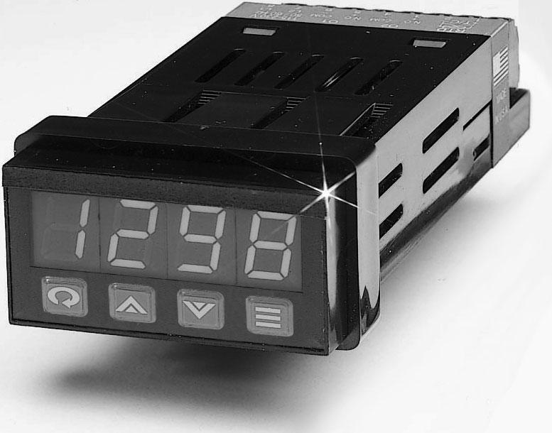
10 Operation Figure 8. Front Panel Controls and Indicators Output Indicator Used to indicate activation of Output 1. Four-Digit LED Display Displays measured process value, setpoint, or parameter labels and settings. Output Indicator Used to indicate activation of Output 2. Power On Mode/Enter Key Used to enter Parameter selections, access operating modes, silence latched alarms, and index through menu items. Lower Key Used to decrease values. (Hold for fast-step progression) Raise Key Used to increase values. (Hold for fast-step progression) Menu Access Key Used to enter or exit the menu system, index to the next menu, and enter the Security Level menu. The Series 32C controller's functional hierarchy is organized into three distinct user-programmable groupings: Security Level, Menu System, and Operating Mode. Please provide the software version number, along with the controller s full model number, when contacting us regarding your controller. When power is first applied to the Series 32C, all segments of the LED display will be momentarily illuminated while the instrument goes through a series of diagnostic checks to verify proper operation. A software version number will then be displayed, e.g.,, followed by the measured process value. IMPORTANT: On initial startup, there is a possibility that outputs may be activated. We recommend placing the unit in Standby mode until you have configured the controller according to your application requirements. To place the controller in Standby, follow this procedure: 1) Mode/Enter key once. 2) Raise key once. 3) Mode/Enter key again. (The display will alternate between and process value. 9
11 Operations Overview The user interface of the Series 32C allows you to use menus to set up the instrument, set the desired security level, change the setpoint, and conveniently change operating modes. Figure 9 provides a functional representation of the user interface and the key presses necessary to perform the basic functions. Security Levels The controller s initial security level, set at the factory, is Configuration. When you have completed configuring the instrument, we recommend the security level be set to the most restrictive level suitable for your application. The security level feature allows you to limit access to the menus, setpoint, and operating mode selection according to the needs of your application. The five security levels provided are Key Lockout, Setpoint, User, Configuration, and Factory. To view or change security level, press and hold the Menu Access key for approximately ten seconds. The controller will alternately display (Access Level) and the current security level label, e.g.,. Use the Raise or Lower keys to index through the security levels. the Mode/Enter key to select the new security level desired and return to the Process Value display. Security Levels and Access Restrictions Key Lockout Highest security level. No access to any controller functions. To escape, follow instructions above for changing security levels. Setpoint No access to menus. Only allows setpoint value, output percentage (manual mode), or operating mode to be changed. User All Setpoint level privileges as well as access to Autotune and Control menus. Configuration All User level privileges as well as Input, Output, Display, and Supervisor menus. Factory All Configuration level privileges as well as access to Calibration menu. 10
12 Menu System If a key press is not sensed within five minutes, the controller automatically exits the Menu System and reverts to the Process Value display. The Menu System is organized into seven menus: Control, Autotune, Input, Output, Display, Supervisor, and Calibration. ing the Menu Access key indexes from menu to menu. ing the Mode/Enter key indexes through the parameters in a particular menu. The Raise and Lower keys are used to modify the visible menu parameter. Each menu contains a logical group of parameters related to one another. Furthermore, the sequence of the menus has been carefully chosen to put the most frequently used menus first. For example, provided access is permitted, the first menu presented upon entering the Menu System is the Setpoint Menu. 11
13 Menu System Menu System Figure 9. Series 32C Functional Diagram Setpoint Modification for 3 seconds Security Levels for 10 seconds Process Variable Display Mode Selection for 3 seconds 12
14 Menu System Figure 10. Overview of Series 32C Menu System, Operating Modes, and Security Levels Menu Access Key Mode/Enter Key 13
15 Mode/Enter Key Raise/Lower Key Security Levels (Key Lockout) = No Access (Setpoint) = (User) = Plus (Configuration) = Plus (Factory) = Plus 14
16 Initial Setup Sequence If a key press is not sensed within five minutes, the Menu System is automatically exited and the controller reverts to the Operating Mode/ Process Value display. These setup instructions apply to PID-type control outputs. Alarm or on/off output settings and displays will be different. Refer to Output menu description on page 19. Many of the menu parameters you will need to set up the controller for your application are interdependent. We recommend following the steps below when configuring your Series 32C. 1) Place the unit in Standby Mode as follows. the Mode/Enter key for three seconds. Display will indicate. the Raise key to select Standby. Mode key again and the display will alternate between and the process value. 2) Input Type. Menu Access key repeatedly until is displayed. Then press Mode/Enter key until appears. Use Raise or Lower key to select Input Type. If Input Type is set to linear or, use the Mode/Enter key to scroll to scaling limits, and, before proceeding. Use the Raise or Lower key to set low and high scaling limits. 3) Output Type. the Menu Access key to display. Use the Mode/Enter key to index to the Output Type parameter. Using the Raise or Lower keys, select the correct Output Type for your application. Follow these steps (using the Mode/Enter and Raise or Lower keys) to set the Output Action, Cycle Time, and High Limit parameters for all control outputs. 4) Set Control Menu parameters by pressing the Menu Access key to display. Then, use the Mode/Enter key to index through the available selections and the Raise or Lower keys to select the appropriate setting. 5) Return to Process Variable Display. and hold the Menu Access key for three seconds to return to PV display. 6) Adjust setpoint. the Menu Access key once to display and use the Raise or Lower key to enter the desired setpoint. the Mode/Enter key to return to the Standby/Process Value display. Wait for process to stabilize before proceeding, e.g., in the case of a heating process, return to ambient temperature. If autotuning the controller, make sure the Autotune Damping parameter is set to normal and proceed to Step 4 on page 33. 7) Security Level. and hold the Menu Access key for approximately ten seconds. Using the Raise or Lower keys, set the most restrictive level suited to your application. 15
17 Menus and Parameters IMPORTANT: Upon entering a new value, you MUST either press the Mode/Enter key, the Menu Access key, or index to a different parameter in order for the new value to register. The Series 32C controller will NOT accept new values without a key press. Menus and Parameters or Setpoint % Output Control Autotune Input Output Display Supervisor Calibration Used to change the setpoint or Fixed Output Percentage (Manual operating mode). Used to select parameters associated with the control methods. Used to set the autotune damping parameter. Used to select sensor-related parameters, such as input type, limits, and scaling. Used to specify output usage, control methods, and alarms. Used to set or change decimal position and display units. Used to set the failsafe state of the controller. Used to calibrate the controller. 16
18 Setpoint Menu Display Parameter Selection Default In Manual mode, the setpoint display is replaced by the manually controlled output percentage display. Control Menu Setting Derivative (Rate) or Integral (Reset) to disables that aspect of PID control. If BOTH outputs are set to direct-acting or BOTH outputs are set to reverse-acting, then only one proportional band selection will be displayed. The second proportional band is not required. Setpoint Setpoint limits 72 F NOTE: In Manual operating mode, setpoint is not displayed. Manually controlled output percent when not configured for two same-acting outputs. 0...High limit Bumpless Manually controlled output percent for output 1 when configured for two same-acting outputs. 0...High limit Bumpless Manually controlled output percent for output 2 when configured for two same-acting outputs. 0...High limit Bumpless NOTE: Output percent parameters are not displayed unless the controller is in Manual operating mode. Display Parameter Selection Default The following parameters are only available if their related outputs are set for PID. Proportional Band to span of sensor Span NOTE: Only available if Output 1 has been set for PID control. Proportional Band to span of sensor Span NOTE: Only available if Output 2 has been set for PID control. Derivative Action (Rate) 0 to 2400 seconds 0 seconds Manual Reset -100% to 100% Off NOTE: When OFF is selected for the Manual Reset parameter, the Integral Action (Int) parameter is active. Integral Action (Reset) 0 to 9600 seconds 0 seconds The following parameters are only available if their related outputs are set for ON/OFF. Deadband to span of sensor 1 F Hysteresis Output to span of sensor 1 F Deadband to span of sensor 1 F Hysteresis Output to span of sensor 1 F 17
19 Autotune Damping Menu Display Parameter Selection Default The following parameters are only available if their related outputs are set for PID. Proportional Band to span of sensor Span NOTE: Only available if Output 1 has been set for PID control. Proportional Band to span of sensor Span NOTE: Only available if Output 2 has been set for PID control. Note: The damping parameter is an autotune feature that allows you to modify the calculated PID control method used to tune the controller to suit your specific application requirements. The low setting provides faster recovery, but with the possibility of overshoot; the high setting a slower recovery, but with no overshoot. Input Menu Changing Low Scale or High Scale for linear inputs will reset the following parameters: Setpoint High Limit, Setpoint Low Limit, Output 1 Alarm Setpoint, Output 2 Alarm Setpoint, Proportional Bands. High Scale and Low Scale cannot be adjusted to less than two display units from each other. Input Menu Display Parameter Selection Default Low Scale to High Scale to NOTE: Only available if one of the two linear input formats has been selected. Lower Setpoint Limit Span of Sensor low scale Upper Setpoint Limit* Span of Sensor high scale Input Type Type J thermocouple (Default) Type K thermocouple Changing Input Type will reset the following parameters to their default settings: Setpoint Proportional Band 1 Proportional Band 2 Output 1 Deadband Output 1 Hysteresis Output 2 Deadband Output 2 Hysteresis Output 1 Alarm Setpoint Output 2 Alarm Setpoint. Type T thermocouple 100 ohm platinum RTD 100 ohm decimal RTD 0-50 mvdc or 0-20 madc mvdc or 4-20 madc *Note: The SP.HL parameter is the maximum setpoint that can be entered. This parameter is limited to 392 F when displaying process temperature with 0.1 degree accuracy (Available only with 100-ohm decimal RTD Input Type). 18
20 Output Menu Parameters not associated with Output 1 Type or Output 2 Type selection will not be displayed. Ex., Alarm parameters will not be displayed when PID control output is selected. Display Parameter Selection Default Output 1 Type Output 1 Action Output 1 Alarm Action Output 1 Process/ (Reverseacting) (Direct-acting) (Latching) (Normal) (Process Low) Deviation (Process High) (Inverse Band) (Normal Band) (Deviation Low) (Deviation High) Output 1 Alarm Span of Sensor 25 C Setpoint Output 1 (Disabled) Alarm Inhibit (Enabled) Output 1 Cycle Time 0 to 120 seconds 0=300 ms NOTE: Only available if Output 1 has been set to PID. Output 1 High Limit 1-100% 100% 19
21 Output Menu (Reverseacting) (Direct-acting) Setting output cycle time to initiates a 300 ms cycle time. The proper cycle time setting is required for smooth proportional action. Too long a setting will cause proportional ripple; too short will decrease relay contactor life. When changing thermocouple types, be sure to check/adjust upper and lower setpoint limit values. If both outputs are set to, the Series 32C will function as a noncontrolling indicator. Control outputs will be disabled and the Operating Modes will not be displayed. Output 2 Type Output 2 Action Output 2 Alarm Action Output 2 Process/ Deviation (Latching) (Normal) (Process Low) (Process High) (Inverse Band) (Normal Band) (Deviation Low) (Deviation High) Output 2 Alarm Span of Sensor 25 C Setpoint Output 2 (Disabled) Alarm Inhibit (Enabled) Output 2 Cycle Time 0 to 120 seconds 0=300 ms NOTE: Only available if Output 2 has been set to PID. Output 2 High Limit 1-100% 100% 20
22 Display and Supervisor Menu Display Parameter Selection Default Decimal Position OR NOTE: This parameter selection is available only for the 100-ohm decimal RTD Input Type. It does not appear for thermocouple or non-decimal 100-ohm platinum RTD inputs (see page 25). Changing Decimal Position will cause changes in the following parameters: Setpoint High Limit, Setpoint Low Limit, Low Scale, High Scale, Setpoint, Proportional Bands, Hysteresis. Display Units The Failsafe State is only enforced when a problem is detected with the process input. It is not reliably enforceable in instances of internal circuitry failure such as EEPROM problems. Output % High Limits are ignored when the unit enters a Failsafe State. NOTE: Does not appear for linear inputs. Supervisor Menu Display Parameter Selection Default Failsafe State (Reverse-acting) (Direct-acting) NOTE: The Failsafe State is used when an open-sensor, over range, or underrange condition exists. The OFF setting deactivates both outputs. The re setting activates reverse-acting outputs and deactivates direct-acting outputs.the dir setting activates direct-acting outputs and deactivates reverse-acting outputs. Note on Calibration Menu: Your Series 32C was calibrated at the factory. If recalibration should become necessary, see page
23 Operating Modes Remember to press the Mode/Enter key after making your selection. If both outputs are set to or, the Series 32C will function as a noncontrolling indicator. Control outputs will be disabled and the Operating Modes will not be displayed. The Series 32C features four operating modes: Manual, Standby, Normal, and Autotune. To select a different operating mode, press the Mode/Enter key for three seconds. The first option displayed is Manual (Fixed Output Percentage) Mode. To index through the available operating modes, press the Raise or Lower keys. When the desired mode is displayed, press the Mode/Enter key once to select the mode. Manual Autotune Normal Standby (only available when unit is placed in Standby mode.) A description of the available operating modes is provided on the next page. 22
24 Operating Modes Manual operating mode overrides automatic control, allowing you to control the outputs using a fixed percentage of output power, regardless of the process variable or setpoint. An Output High Limit, which restricts the output percentage possible in Manual mode may be entered in the Output menu. If current automatic control is PID, transfer to Manual mode is bumpless. Manual Standby Normal Autotune Used to set control output percentage (Fixed Output Percentage) independent of Process Value. To set percentage, use the Menu Access key to select and the Raise or Lower keys to set the value. If BOTH outputs are direct-acting or BOTH outputs are reverse-acting, then two FOP percentages will be displayed. and. Used to disable control outputs. Normal automatic control. Used to initiate the autotuning sequence (from Standby only). Alarms Deviation, Inverse Band, and Normal Band Alarm track with setpoint. When a latching alarm has been activated and the alarm condition has been removed, the Mode/Enter key must be pressed to unlatch the alarm. 23 Four types of alarms are available on both Output 1 and Output 2: Process, Deviation, Inverse Band, and Normal Band. Both output alarms may be configured to be inhibited on power-up (until the process reaches setpoint for the first time). Process Alarm: Activates at preset value, independent of setpoint. High process alarm activates at and above alarm setting. Low process alarm activates at and below alarm setting. Deviation Alarm: Activates at a preset deviation value from setpoint. High or Low deviation alarm activates above or below setpoint according to the preset deviation value. Inverse Band Alarm: Activates when the process is within a specified band centered around the setpoint. Normal Band Alarm: Activates when the process exceeds a specified band centered around the setpoint. Latching Alarms The Series 32C s alarms may also be configured as latching alarms by selecting in the Output 1 or Output 2 Alarm Action or parameter selection.
25 Available Control Methods The user-selectable control method options provided by the Series 32C controller are On/Off, PID (including subsets P, PI, PD, P/Manual Reset, PD/Manual Reset), or Manual. Use the Output menu to select On/Off or PID output action and the Control menu to enable or disable the derivative, integral, and manual reset selections as desired. Use the (Fixed Output Percentage) operating mode to enable Manual operation. Output Menu Select PID or On/Off Control Menu (PID) Proportional Band 1 Proportional Band 2 Derivative Manual Reset Integral 24
26 Autotuning In order for the controller to autotune properly, the setpoint value must be at least 1% of span above or below the initial process value. Ex. sensor span = 1548 (Type J thermocouple); acceptable setpoint value = ±16 (15.4) units from the initial process value. Tuning accuracy increases as the spread between ambient and setpoint value increases. While some processes other than heat or cool applications may respond successfully to autotuning procedures, the controller must be manually tuned for most non-temperature processes. To place the Series 32C in Autotune mode: 1) Configure the controller by following the directions for Initial Setup Sequence through Step 5 on page 15. Set damping to normal. (See page 18.) 2) If the controller is not already in Standby mode, place it in Standby now as follows. and hold the Mode/Enter key for 3 seconds. Display will indicate. the Raise key to select Standby. Mode key again and the display will alternate between and the process value. 3) If Setpoint Value has not been entered, adjust setpoint now by pressing the Menu Access key once. The Setpoint menu, alternating with the Setpoint Value, will flash. (If not, press the Menu Access key for three seconds to return to the Standby/Process Value display, then press it once again.) Use the Raise or Lower key to set the desired setpoint. the Mode/Enter key to return to the Standby/Process Value display. Wait for process to stabilize before proceeding, e.g., in the case of a heating process, return to ambient temperature. 4) Initiate Autotuning. and hold the Mode/Enter key for 3 seconds, then press the Lower key once. Finally, press the Mode/Enter key again. The display will alternately indicate and process value as the controller learns the proper gain, derivative, and integral values for the process. If unacceptable overshoot occurs on restart, shut down the process and re-tune at the high damping setting. If sluggish response is observed, shut down the process and re-tune using low damping. 25
27 Manual Tuning Manual Tuning Procedure - Heating Process (Zeigler-Nichols PID Method) This tuning method may be used if the spread between ambient and operating temperature is small, and the autotuner is, therefore, disabled. It may also be used on non-temperature reverse-acting processes. 1) Disable cooling device. 2) Turn off the Direct-Acting output. 3) Under the Control menu, set derivative and integral to zero, and the proportional band or to its maximum setting. 4) Adjust the setpoint to the desired value. 5) While monitoring the recording device, decrease the proportional band value by repeatedly halving the value until a small, sustained temperature oscillation is observed. Measure the period of one cycle of oscillation ( T on the diagram below). T 6) Divide the period of oscillation (T) by eight. The resulting number is the correct Derivative time in seconds. Multiply this number by four. This is the correct Integral time in seconds. 7) Multiply the bandwidth value obtained in Step 7 by 1.66 and enter this as the new proportional band value. 26
28 Error Codes If an error code through cannot be cleared by using the actions provided, contact factory. Display Problem Actions RAM Diagnostic Test Failure any key to ROM Diagnostic Test Failure perform a soft EEPROM Range Test Failure reset and or EEPROM Update Failure reinitialize SPI/EEPROM Interface Failure controller. Default EEPROM Load Warning Open Sensor Reversed Sensor Check sensor, wiring, and Input Type selection in the Input menu. Technical Specifications 27 Operating Limits Ambient Temperature Relative Humidity Tolerance Power Power Consumption Performance Accuracy Setpoint Resolution Repeatability Temperature Stability TC Cold-End Tracking Noise Rejection Process Sampling Control Characteristics Setpoint Limits Alarms Proportional Band Integral Derivative 32 F to 131 F (0 C to 55 C) 90%, Non-Condensing 85 to 250 Vac 50/60 Hz (Single-Phase) Less than 6 VA ±0.20% of Full Scale (±0.10% Typical), ±1 Digit 1 Count / 0.1 Count ±1 Count 5 µv / C (Maximum) 0.05 C / C Ambient >100 db Common Mode, >70 db Series Mode 3.7 Hz (270ms) Automatically Adjust to Selected TC / RTD Adjustable for High / Low; Selectable Process or Deviation 1 to Span of Sensor 0 to 9600 Seconds 0 to 2400 Seconds
29 Technical Specifications Operating Limits Ambient Temperature Relative Humidity Tolerance Power Power Consumption Performance Accuracy Setpoint Resolution Repeatability Temperature Stability TC Cold-End Tracking Noise Rejection Process Sampling Control Characteristics Setpoint Limits Alarms Proportional Band Integral Derivative Cycle Time Control Hysteresis Autotune Manual Control 32 F to 131 F (0 C to 55 C) 90%, Non-Condensing 85 to 250 Vac 50/60 Hz (Single-Phase) Less than 6 VA ±0.20% of Full Scale (±0.10% Typical), ±1 Digit 1 Count / 0.1 Count ±1 Count 5 µv / C (Maximum) 0.05 C / C Ambient >100 db Common Mode, >70 db Series Mode 3.7 Hz (270ms) Automatically Adjust to Selected TC / RTD Adjustable for High / Low; Selectable Process or Deviation 1 to Span of Sensor 0 to 9600 Seconds 0 to 2400 Seconds 0 = 300 ms; 1 to 120 sec 1 to Span of Sensor Operator Initiated from Front Panel Operator Initiated from Front Panel Mechanical Characteristics Display 7-segment LED, alphanumeric Numeric Range to 9999 Display Height 0.400" Color Green Front-Panel Cutout 0.874" x 1.772" (22.19 mm x 45 mm) Bezel Outside Dimensions 0.944" x 1.890" (24 mm x 48 mm) Bezel Height 0.328" (8.33 mm) Case Depth 3.937" (100 mm) Weight 3.04 oz (86.18 g) Connections Input and output via removable barrier strip. 28
30 Technical Specifications Inputs Thermocouple RTD J, K, T Maximum lead resistance 100 ohms for rated accuracy Platinum 2-wire, 100 ohms at 0 C, DIN curve standard ( ) Linear 0-50 mv/10-50 mv, 0-20 ma/4-20 ma with external 2.5 ohm shunt resistor Input Impedances 0-50 mv/10-50 mv: 1 K ohm ±1% 0-20 ma/4-20 ma: 2.5 ohm ±1% Outputs Type R Type T Type DC Electromechanical relay, Vac, Vac Solid-state relay, 120/250 Vac, zero voltage-switched, 1 A continuous / 10 A 25 C. 5 Vdc pulsed (open collector) 29
31 Ordering Information 32C U Outputs (Heat/Cool)* Code BS = Output #1 Relay, #2 Pulsed (Logic) TT = Outputs #1 and #2 S.S. Relay BT = Output #1 Relay, #2 S.S. Relay SS = Outputs #1 and #2 Pulsed (Logic) ST = Output #1 Pulsed (Logic), #2 S.S. Relay *Note: Both outputs must be configured in the field as either direct-acting or reverseacting. Outputs Code 1 = 24 Vac/dc power Special Options Consult Factory Input Ranges (Inputs are field-configurable from the front-panel menu and calibrated at the factory for all input types. No recalibration is required when switching from one input type to another. Input F C T/C K -220 to to 1350 J -398 to to 760 T -202 to to 400 RTD 100 ohm RTD -328 to to ohm RTD to to (Decimal) Linear Scaleable 10 to 50 mv 4 to 20 ma 0 to 50 mv 0 to 20 ma 30
32 Recalibration Procedures The Series 32C controller is precalibrated at the factory. Under normal circumstances, the factory calibration should be valid for the life of the instrument. If recalibration should be required, allow the controller to warm up for 15 minutes and follow these steps carefully. 1) Remove power from the controller, then all wires from terminals 1 through 6. Attach an appropriate sensor emulator to input terminals 1 and 2. 2) Power on the sensor emulator, making sure that the current emulated value is not outside the range of the Series 32C. Then, power on the Series 32C. 3) Index to the Calibration Low menu item in the Calibration Menu. (You must have the Security Level set to Factory to access this menu.) 4) For thermocouples and RTDs, dial the low calibration values into the sensor emulator using the table below. For linear inputs, calibrate from low scale. Sensor Type Calibration Low Calibration High J 0 C/32 F 760 C/1400 F K 0 C/32 F 1350 C/2462 F T 0 C/32 F 400 C/ 752 F RTD 0 C/32 F 850 C/1562 F RT.D (decimal) 0 C/32 F C/392.0 F 5) Use the Raise or Lower Keys to match the values shown on the display to the extracted table value. 6) Push the Mode/Enter Key to index to the Calibration High menu item. 7) Repeat Steps 4 and 5 for the Calibration High setting. 8) the Menu Access key for three seconds to return to the Process Value display. 31
33 Quick-Helps 1. To return the unit to last operating mode (Normal, Standby, FOP, or Tune): Action Display From Menu System: and hold PV/Mode for 3 sec. From Security Level Menu: PV/Mode 2. To enter Standby operating mode: Action Display From Normal operating mode: and hold for 3 sec. + PV From FOP (Manual) operating mode and hold for 3 sec. + PV From Menu System: and hold for 3 sec. and hold for 3 sec. + PV From Security Level Menu: and hold for 3 sec. PV + PV 32
34 Quick-Helps 3. To escape from Standby operating mode: Action Display and hold for 3 sec. PV 4. To initiate Autotuning: Action Display Enter Standby operating mode (See Quick-Help #2) and hold for 3 sec. + PV 5. To abort Autotuning: Action Display and hold for 3 sec. + PV and hold for 3 sec. PV 33
35 Quick-Helps 6. To enter FOP (Manual) operating mode: Action Display and hold for 3 sec. + PV + % of Power Value or + % of Power Value to set new % of Power Value + PV 7. To escape from FOP (Manual) operating mode: Action Display and hold for 3 sec. PV 34
36 Warranty/Repair Information Two-Year Limited Warranty Other than those expressly stated herein, THERE ARE NO OTHER WARRANTIES OF ANY KIND, EXPRESS OR IMPLIED, AND SPECIFICALLY EXCLUDED BUT NOT BY WAY OF LIMITATION, ARE THE IMPLIED WARRANTIES OF FITNESS FOR A PARTICULAR PURPOSE AND MERCHANTABILITY. IT IS UNDERSTOOD AND AGREED THE SELLER S LIABILITY WHETHER IN CONTRACT, IN TORT, UNDER ANY WARRANTY, IN NEGLIGENCE OR OTHER- WISE SHALL NOT EXCEED THE RETURN OF THE AMOUNT OF THE PUR- CHASE PRICE PAID BY THE PURCHASER AND UNDER NO CIRCUMSTANCES SHALL SELLER BE LIABLE FOR SPECIAL, INDIRECT, INCIDENTAL OR CON- SEQUENTIAL DAMAGES. THE PRICE STATED FOR THE EQUIPMENT IS A CONSIDERATION IN LIMITING SELLER S LIABILITY. NO ACTION, REGARD- LESS OF FORM, ARISING OUT OF THE TRANSACTIONS OF THIS AGREE- MENT MAY BE BROUGHT BY PURCHASER MORE THAN ONE YEAR AFTER THE CAUSE OF ACTION HAS ACCRUED. SELLER S MAXIMUM LIABILITY SHALL NOT EXCEED AND BUYER S REME- DY IS LIMITED TO EITHER (i) REPAIR OR REPLACEMENT OF THE DEFEC- TIVE PART OR PRODUCT, OR AT SELLER S OPTION (ii) RETURN OF THE PRODUCT AND REFUND OF THE PURCHASE PRICE, AND SUCH REMEDY SHALL BE BUYER S ENTIRE AND EXCLUSIVE REMEDY. Unit Repairs It is recommended that units requiring service be returned to an authorized service center. Before a controller is returned for service, please consult the service center nearest you. In many cases, the problem can be cleared up over the telephone. When the unit needs to be returned, the service center will ask for a detailed explanation of problems encountered and a Purchase Order to cover any charge. This information should also be put in the box with the unit. This should expedite return of the unit to you. This document is based on information available at the time of its publication. While efforts have been made to render accuracy to its content, the information contained herein does not cover all details or variations in hardware, nor does it provide for every possible contingency in connection with installation and maintenance. Features may be described herein which are not present in all hardware. Athena Controls assumes no obligation of notice to holders of this document with respect to changes subsequently made. Proprietary information of Athena Controls, Inc. is furnished for customer use only. No other use is authorized without the written permission of Athena Controls, Inc. 35
37 IEC Requirements USE OF THIS EQUIPMENT IN A MANNER NOT SPECIFIED BY THE MANUFACTURER MAY IMPAIR PROTECTION PROVIDED BY THE EQUIPMENT! The maximum supply current is line voltage dependent: 230 ma for a 24 Vac input fuse rating=700 ma 60 ma for an Vac input fuse rating=100 ma Output Specifications Output Type Max current Voltage Leakage R 5 A 380 Vac 1000M Ohms T 1 A 400 Vpk 1 ma DC 20 ma 5 V NA CLEANING INSTRUCTIONS 1. Remove power from the unit prior to any cleaning operation. 2. Use a cotton cloth to gently and sparingly apply isopropyl alcohol only. Do not use cleaners or other solvents as they may damage the unit. 3. Allow the unit to dry completely prior to reapplying power. 36

38 Quick Setup Instructions - Series 32C Temperature Controller Experienced users, already familiar with the Series 32C, and using the controller with PID outputs, may follow these condensed instructions to autotune the controller and get started quickly once the instrument is properly mounted and wired, and the Security Level is set to. Once setup is complete, we recommend changing the Security Level back to the most restrictive level suitable for your application. These quick setup instructions are not meant as a substitute for reading the full instruction manual supplied with the controller. Please be sure to read through the manual for specific details of operation and, most importantly, for safety precautions. If you have any questions, or experience problems with setting up your controller, consult the full instruction manual first and, if you still need assistance, contact your Athena representative or call Menu Access Raise Lower Mode/Enter 1. Apply power. After self-check display stops, place controller in Standby mode by pressing and holding the key for 3 seconds, the key once, and then the key again. will flash, alternating with the Process Value. 2. repeatedly until is displayed. Then press the key repeatedly until appears. Use or to select sensor input type. 3. to display. Then press once to display. Use or to select. 4. the key until Output 1 Action is displayed. Select the desired output action using the or keys. = Heating = Cooling 37
39 5. again to display the Output 1 Cycle Time parameter. Select the desired cycle time according to the output device used. If unsure, refer to the ordering code on page 40 of the instruction manual and compare it to the number on the label. Recommended cycle times are: For Control Output Device Select Cycle Time (in seconds) R (Output 1 only) 15 DC 0 T 15 IMPORTANT: IF ONLY ONE OUTPUT IS PID, SET THE OTHER OUTPUT TO EITHER ON/OFF, ALARM, OR OFF. 6. the key to display the next output parameter, Output 1 High Limit, and select the desired value using the or keys. 7. Repeat Steps 3 through 6 for Output 2 if required; otherwise, repeat Step 3 to select other Output Type. 8. the repeatedly until is displayed, then press and make sure autotune damping parameter is set to normal. If not, use or to change it to the normal setting. 9. and hold the Menu Access key for 3 seconds until flashes. 10. Initiate autotuning per chart below. Hold for 3 Seconds Once. Appears in Window Once Flashes The Controller Is Now Autotuning 11. If unacceptable overshoot occurs, shut down the process and allow it to stabilize. Re-tune at the high damping setting. If response is sluggish, use the low damping setting. 38
40 For technical assistance, call toll free (in the U.S.) or (from anywhere in the world), or Athena Controls, Inc Campus Drive Plymouth Meeting, PA USA Toll-free: Tel: Fax: athenacontrols.com 900M008U00 REV B /
Nov 08 PRODUCT SPECIFICATION SHEET
 Honeywell UDC1200 and UDC1700 MICRO-PRO SERIES UNIVERSAL DIGITAL CONTROLLERS 51-52-03-35 Nov 08 PRODUCT SPECIFICATION SHEET OVERVIEW The UDC1200 & UDC1700 are microprocessor-based 1/16 DIN and 1/8 DIN
UDC1000 and UDC1500 MICRO-PRO SERIES UNIVERSAL DIGITAL CONTROLLERS
 UDC1000 and UDC1500 MICRO-PRO SERIES UNIVERSAL DIGITAL CONTROLLERS EN0I-6041 4/01 PRODUCT SPECIFICATION SHEET OVERVIEW The UDC1000 and UDC1500 are microprocessor-based 1/16 DIN and 1/8 DIN controllers
Temperature Controllers
 Model TEC-4100 1/4 DIN Model TEC-4100 1/4 DIN Temperature Controller Ordering Code: Power Input BOX 1 4 = 90-250 VAC 5 = 11-26 VAC / VDC TEC-4100- Configurable for 4 Programmable Outputs and NEMA 4X/IP65
I/A Series 716C 1/16 DIN Temperature Controller
 Product Specifications I/A Series 716C 1/16 DIN Temperature Controller PSS 2C-1B5 A The Foxboro 716C is a powerful compact, 1/16 DIN, microprocessor-based temperature controller that offers a variety of
VERTEX VT10 SERIES PID OPERATION MANUAL MICROPROCESSOR BASED PID CONTROLLER
 1 VERTEX VT10 SERIES PID OPERATION MANUAL MICROPROCESSOR BASED PID CONTROLLER 1. INTRODUCTION This manual contains information for the installation and operation and tuning of our Vertex VT10 series self-tuning
Tempco Part Number PCT30006 Temperature Control Enclosure with Relay Output for Tote Tank Heating Applications
 Instruction Manual Tempco Part Number PCT30006 Temperature Control Enclosure with Relay Output for Tote Tank Heating Applications Manual PCT30006, Revision 9/20/2016 The PCT30006 control enclosure incorporates
OVEN INDUSTRIES, INC.
 OVEN INDUSTRIES, INC. OPERATING MANUAL Model 5C7-252 TEMPERATURE CONTROLLER With PLC Inputs Introduction Thank you for purchasing our controller. The Model 5C7-252 is an exceptionally versatile unit and
Tempco PCT-3000 Series Temperature Control Console with Relay Output for Heating or Cooling Applications
 Instruction Manual Tempco PCT-3000 Series Temperature Control Console with Relay Output for Heating or Cooling Applications Manual PCT-3000 Revision 9/2014 The PCT-3000 series control console incorporates
02/11/2015
 MIC48 With RS 485 link Part number 89422418 Heating and / or cooling function 2 independent alarms Load break detection 2 setpoint which can be selected remotely Manual / automatic power adjustment RS
TC515 and TC600 Installation Manual. a Winters company
 THERMOLINE TEMPERATURE CONTROLLERS TC515 and TC600 Installation Manual a Winters company Guarantee 12 months Congratulations on the purchase of this new product. Special care with the design, workmanship
F4 Process Controller Installation and Operation Guide
 F4 Process Controller Installation and Operation Guide 1.Introduction 1.1.Highlight Features Space saving, only 55mm panel depth required Higher sampling rate (1mS) results in better control performance
UDC 700 Universal Digital Controllers and Indicator Specifications
 UDC 700 Universal Digital Controllers and Indicator Specifications 51-52-03-28 August 2002 Overview The UDC 700 is a 1/32 DIN (49 x 25 mm) controller which combines a high degree of technology and quality
UDC100 Universal Digital Controller Specifications
 UDC100 Universal Digital Controller Specifications 51-52-03-29 November 1999 Overview The UDC100 Universal Digital Controller is a microprocessor-based 1/4 DIN low cost temperature controller. It combines
AutomationDirect PM24. Microprocessor - Based Process/Temperature Limit Controller. Operator s Manual. Technical Support.
 AutomationDirect 1/16 DIN Series Technical Support We strive to make our manuals the best in the industry. We rely on your feedback to let us know if we are reaching our goal. If you cannot find the solution
Digi-Sense TC9000 Advanced PID and On/Off Temperature Controller with Thermocouple Input
 User Manual 99 Washington Street Melrose, MA 02176 Phone 781-665-1400 Toll Free 1-800-517-8431 Visit us at www.testequipmentdepot.com Digi-Sense TC9000 Advanced PID and On/Off Temperature Controller with
02/11/2015
 CTH 46 - CTD 43 / 46 CTD 46 Part number 89422108 CTH 46 Heating / cooling function Measurement and setpoint display CTD 43 Heating or cooling function Measurement display Measurement deviation display-setpoint
Model 96VTR ¼ DIN Process Controller
 99 Washington Street Melrose, MA 02176 Phone 781-665-1400 Toll Free 1-800-517-8431 Visit us at www.testequipmentdepot.com Back to the Extech 96VTR Product Info Page INSTRUCTION MANUAL Model 96VTR ¼ DIN
99 Washington Street Melrose, MA Phone Toll Free Visit us at
 99 Washington Street Melrose, MA 02176 Phone 781-665-1400 Toll Free 1-800-517-8431 Visit us at www.testequipmentdepot.com Back to the Extech 48VTR Product Info Page Instruction Manual English / Español
VT4810 SINGLE / DUAL ZONE CONTROLLER INSTALLATION MANUAL
 Thermocouple Type BS4937 (IEC584-3): Outer / + / - BS1843 (Old UK Standard) Outer / + / - US Outer / + / - J : Iron / Copper-Nickel Black / Black / White Black / Yellow / Blue Black / White / Red VT4810
Process & TeMPerATUre UniversAl input DigiTAl MeTers
 Process & TeMPerATUre UniversAl input DigiTAl MeTers nova PD56 series Thermocouple, rtd, & Process inputs Universal Power supply 1-24 va c Up to 3 Alarm relays retransmitting 4-2 ma output input Max/Min
DE20 INSTRUCTION MANUAL
 DE20 INSTRUCTION MANUAL Now UL Listed! SET POINT DE20 SET YOUR DISTRIBUTOR: Chemical Distributors, Inc. 80 Metcalfe Street - Buffalo, NY 14206 Phone: 800-777-2436 716-856-2300 Fax: 716-856-7115 sales@cdibuffalo.com
PROCESS & TEMPERATURE UNIVERSAL INPUT DIGITAL METERS
 PROCESS & TEMPERATURE UNIVERSAL INPUT DIGITAL METERS NOVA PD56 Series Thermocouple, RTD, & Process Inputs Universal Power Supply 1-24 VAC Up to 3 Alarm Relays Retransmitting 4-2 ma Output Input Max/Min
Series Temperature Controller Instruction Sheet
 Series Temperature Controller Instruction Sheet Thank you very much for purchasing DELTA A Series. Please read this instruction sheet before using your A series to ensure proper operation and please keep
Table of Contents SECTION PAGE
 Table of Contents SECTION PAGE SECTION 1 INTRODUCTION................... 1.1 Description.............................. 1.2 Features................................ 1.3 Models.................................
Sentry LIQUID LEVEL GAUGE MODEL 200 or 200C OWNER MANUAL REV 1.7 SEPT08 PAGE 1 OF 12
 PAGE 1 OF 12 TABLE OF CONTENTS PAGE 1. SAFETY PRECAUTIONS 1.1. Electrical shock 3 2. APPLICATION 3 3. INSTALLATION 3.1. Mount indoor alarm display 3.2. Mount the outdoor junction box 3.3. Install interconnecting
DIGITAL METERS Large Display Temperature Meters Instruction Manual
 DIGITAL METERS Large Display Temperature Meters PD755 PD756 PD757 Handles Thermocouple & RTD Inputs with Simplicity J, K, T, E, R, & S Thermocouples 100 Ω Platinum RTD (0.00385 or 0.00392 curve) Large
Specification , July 2015
 Technical Information PrecisionLine Controllers EDC21 / EDC22 / EDC23 EASYSET DIGITAL CONTROLLERS Specification 51-52-3-48, July 215 Introduction The EDC21, EDC22 and EDC23 controllers provide precise
ESSEX ENGINEERING CORPORATION
 WATER/WASTEWATER TREATMENT CONTROL SYSTEMS AND SUBSYSTEMS 2000 SERIES CONTROL SYSTEMS: 2000 series are for surface mounting inside a control cabinet Model 2024 Electronic Alternator Duplex (two pump) pump
CONsOlIDATOR 4 & 8. MulTI- C h ANNEl CONTROllERs. ConsoliDator 4 Model PD940 ConsoliDator 4 Features. ConsoliDator 8 Features.
 CONsOlIDATOR 4 & 8 MulTI- C h ANNEl CONTROllERs ConsoliDator 4 Model PD940 ConsoliDator 4 Features Four 4-20 Four 4-20 Outputs ConsoliDator 8 Features Eight 4-20 Two 4-20 Outputs Common Features Four Pulse
TEMPERATURE CONTROLLER
 TEMPERATURE CONTROLLER E5CX(-H) DIN-sized super-compact (48 x 48-mm) Temperature Controller Featuring Advanced PID Control Advanced PID control with two degrees of freedom improves stability and response
VERTEX F4 Instruction Manual
 VERTEX F4 Instruction Manual 02/2018 The VERTEX F4 controller 1/16 DIN is our LOW COST yet HIGH SPEC controller. Configurable on input between various thermocouples from the keypad by the user or when
Oakton TEMP 9500 Advanced Multiparameter Controller
 Oakton TEMP 9500 Advanced Multiparameter Controller Models: 89800-03 & 89800-04 Oakton Instruments 625 E Bunker Ct. Vernon Hills, IL 60061, USA 1-888-4OAKTON (1-888-462-5866) info@4oakton.com Contents
R1000 / R1040 / R1080
 R1000 / R1040 / R1080 1 Zone Temperature Controller: Heat-only Heating-off-cooling Three-point stepping DIN-Format: 96mm x 96mm / 48mm x 96mm / 96mm x 48mm Description and operating manual ELOTECH Industrieelektronik
AutomationDirect. PC35 Configuration Sheet
 Part#: Project: AutomationDirect PC35 Configuration Sheet Name: Date: Main Setpoint (): Cycle 5 INPUT DEFAULT CODE/VALUE Type 1 Dppo OFF Unit [ Offs 0 Spll -150 Spkl 1370 Rsll -150 Rskl 1370 Cycle 6 I/O
7EF/7HF/7EC/7ES Temperature Controllers
 7EF/7HF/7E/7ES Temperature ontrollers Dual 4 Digit LED Display Universal Input (6 T/, RTD, mv, V, ma) Autotuning NEMA 4X 100 to 240 Vac Switching Power Supply Algorithms for Heat or Heat/ool ontrol 2 Independent
MODELS T16 & P16 - TEMPERATURE/PROCESS CONTROLLERS
 Tel +1 (717) 767-6511 Fax +1 (717) 764-0839 www.redlion.net MODELS & - TEMPERATURE/PROCESS CONTROLLERS Bulletin No. T/-L Drawing No. LP0486 Released 8/13 PID CONTROL WITH REDUCED OVERSHOOT ACCEPTS TC AND
CM 16. Temperature controllers with compact dimensions. Manual 42/61-72 EN Rev. 01
 CM 16 Temperature controllers with compact dimensions Manual 42/61-72 EN Rev. 01 Table of contents Page Remarks... 2 Installation and commissioning 1. Identifying the instrument... 3 2. Selecting installation
ABB MEASUREMENT & ANALYTICS DATA SHEET. C50 1/16 DIN controller / alarm unit
 ABB MEASUREMENT & ANALYTICS DATA SHEET C50 1/16 DIN controller / alarm unit 2 C50 1/16 DI N CON TROLL ER / AL ARM U NIT DS/C 50-E N RE V. M Measurement made easy C50 the 1/16 DIN controller to suit your
Table of Contents SECTION PAGE SECTION 1 INTRODUCTION Description Features Models... SECTION 2 RS-232 COMMUNICATIONS...
 SECTION Table of Contents SECTION 1 INTRODUCTION...................... 1.1 Description............................... 1.2 Features................................. 1.3 Models..................................
INSTALLATION, OPERATING & MAINTENANCE INSTRUCTIONS FOR 870 SERIES INDUSTRIAL CONTROL PANELS
 INSTALLATION, OPERATING & MAINTENANCE INSTRUCTIONS FOR 870 SERIES INDUSTRIAL CONTROL PANELS GENERAL INDEECO Industrial Control Panels are designed to provide years of trouble free operation if properly
eed quality electronic design USER s MANUAL
 eed quality electronic design www.dem-it.com eed www.qeed.it info@qeed.it ANALOG SIGNAL DISPLAY Q-DISP-T USER s MANUAL The displays Q-DISP-T, prepared for mounting on the back panel, 96x48mm, will allow
User Manual. Digi-Sense TC9600 Advanced Multiparameter Temperature Controller with Thermocouple, Thermistor, and RTD Inputs
 User Manual Digi-Sense TC9600 Advanced Multiparameter Temperature Controller with Thermocouple, Thermistor, and RTD Inputs Models 89800-13 and 89800-14 THE STANDARD IN PRECISION MEASUREMENT Table of Contents
Interchangeable thermistor (THE types) Output Contact E5CS-R1KJX-F E5CS-R1PX-F E5CS-R1GX-F Voltage E5CS-Q1KJX-F E5CS-Q1PX-F E5CS-Q1GX-F
 Output Contact E5CS-R1KJX-F E5CS-R1PX-F E5CS-R1GX-F Voltage E5CS-Q1KJX-F E5CS-Q1PX-F E5CS-Q1GX-F") Temperature Controller 1/16 DIN Sized Controller Offers Selectable Control, Alarm Modes Accurate to ±0.5% of full scale Multiple temperature scale ranges allow flexibility to match application Field-selectable
Temperature Controller 1/16 DIN Sized Controller Offers Selectable Control, Alarm Modes Accurate to ±0.5% of full scale Multiple temperature scale ranges allow flexibility to match application Field-selectable
User Manual. Digi-Sense TC9500 Advanced Multiparameter Temperature Controller with Thermocouple, Thermistor, and RTD Inputs
 User Manual Digi-Sense TC9500 Advanced Multiparameter Temperature Controller with Thermocouple, Thermistor, and RTD Inputs Models 89800-03 and 89800-04 THE STANDARD IN PRECISION MEASUREMENT Table of Contents
Communications None RS-232C RS-422* RS-485* BCD Transmission output*/** (4 to 20 ma) E5AX- E5AX- L(M)A02 L(M)A03
 E5AX- E5AX- L(M)A02 L(M)A03") Digital Controller A 96 x 96-mm (DIN) Digital Process Controller Optimum PID control with feed-forward control circuitry. High accuracy (+0.3% FS +1 digit max.). Replaceable Output Units. Models with communications
Digital Controller A 96 x 96-mm (DIN) Digital Process Controller Optimum PID control with feed-forward control circuitry. High accuracy (+0.3% FS +1 digit max.). Replaceable Output Units. Models with communications
DT968C C.T. BATH CONTROLLER
 DT968C C.T. BATH CONTROLLER MANUAL (DT968C, 9-5-01) ICD/HEATEFLEX Page 1 DT968C CONSTANT TEMPERATURE BATH CONTROLLER The Model DT968C is a microprocessor based controller/timer. It monitors temperature
Mark 25 Ultrapure Water Conductivity Analyzer
 Martek Instruments, Inc. Mark 25 Ultrapure Water Conductivity Analyzer Instruction Manual WARRANTY POLICY Unless otherwise stated, MARTEK INSTRUMENTS, INC. warrants this equipment to be free from defects
SA200. General Description. Features. Temperature Controller SA200. Self-Tuning Algorithm. Close Vertical or Horizontal Mounting
 Temperature Controller General Description The is a high performance 3 nd DI controller that has been specifically designed for applications where panel space is critical. Though small in size, this controller
Series: MBC1-TC Mini Benchtop Temperature Controller
 User s Guide Series: MBC1-TC Mini Benchtop Temperature Controller Imagine Instruments LLC:: 4500 Williams Drive, Ste 212-318 :: Georgetown, TX 78633 :: p. 855.574.6243 e-mail: info@imagineinstruments.com
TEMPERATURE CONTROLLER (STANDARD MODEL)
") OPERATING MANUAL TEMPERATURE CONTROLLER (STANDARD MODEL) 689-0000 689-0005 Barnant Company 28W092 Commercial Avenue Barrington, Illinois U.S.A. 60010-2392 (847) 381-7050 (847) 381-7053 (Fax) 800-637-3739
OPERATING MANUAL TEMPERATURE CONTROLLER (STANDARD MODEL) 689-0000 689-0005 Barnant Company 28W092 Commercial Avenue Barrington, Illinois U.S.A. 60010-2392 (847) 381-7050 (847) 381-7053 (Fax) 800-637-3739
INSTRUCTIONS FOR THE 8500 SERIES MICROPROCESSOR BASED TEMPERATURE CONTROL
 INSTRUCTIONS FOR THE 8500 SERIES MICROPROCESSOR BASED TEMPERATURE CONTROL December, 1998 Page 1 949-1275-1 TABLE OF CONTENTS MODEL IDENTIFICATION... 4 INSTALLATION... 4 WIRING... 5 FRONT PANEL KEY FUNCTIONS...
Max HT Air Heater FOR SAFETY & LONG HEATER LIFE, CAREFULLY READ THIS MANUAL BEFORE USE.
 Max HT Air Heater FOR SAFETY & LONG HEATER LIFE, CAREFULLY READ THIS MANUAL BEFORE USE. Safety SHOCK HAZARD! Only qualified individuals should install this heater and related controls. Follow all applicable
CM 8. Temperature controllers with compact dimensions. Manual 42/61-71 EN Rev. 01
 CM 8 Temperature controllers with compact dimensions Manual 42/61-71 EN Rev. 01 Table of contents Page Remarks... 2 Installation and commissioning 1. Identifying the instrument... 3 2. Selecting installation
User s Guide CN616A. Universal 6 Channel ¼ DIN Process Controller. Shop online at omega.com
 TM User s Guide Shop online at omega.com e-mail: info@omega.com For latest product manuals: www.omegamanual.info CN616A Universal 6 Channel ¼ DIN Process Controller omega.com info@omega.com U.S.A. Headquarters:
GG-R REFRIGERANT SENSOR. Installation and Operation Manual
 GG-R REFRIGERANT SENSOR Installation and Operation Manual 2 GG-R Warning Use this product only in the manner described in this manual. If the equipment is used in a manner not specified by Calibration
Controllers. Instruction Manual WARNING
 Controllers Instruction Manual WARNING THIS MANUAL MUST BE CAREFULLY READ BY ALL INDIVIDUALS WHO HAVE OR WILL HAVE THE RESPONSIBILITY FOR INSTALLING, USING OR SERVICING THIS PRODUCT. Like any piece of
UDC1000 & UDC 1500 MICRO-PRO SERIES UNIVERSAL DIGITAL CONTROLLERS
 UDC1000 & UDC 1500 MICRO-PRO SERIES UNIVERSAL DIGITAL CONTROLLERS EN0I-6041 11/98 PRODUCT SPECIFICATION SHEET OVERVIEW The UDC1000 & UDC 1500 are microprocessor-based 1/16 DIN and 1/8 DIN controllers which
PACSystems* RX3i. Thermocouple Input Module, 12 Channels, IC695ALG412. GFK-2578B October 2011
 October 2011 PACSystems* RX3i Thermocouple Input Module, 12 Channels, IC695ALG412 The PACSystems * Thermocouple Input module IC695ALG412 provides twelve isolated differential thermocouple input channels.
SA100. General Description. Features. Temperature Controller SA100. Corresponding to Various Applications. Simple Mounting on DIN Rail
 Temperature Controller General Description The is a socket mounting type temperature controller and is available for mounting inside the panel or by easily mounting on DI rail. The has features such as
CELLTROL II BIOREACTOR CONTROL SYSTEM OPERATIONS MANUAL
 Operation Manual Celltrol II Bioreactor Control System Page 1 of 33 Table of Contents 1) Introduction... 3 1.1) Scope of Document... 3 1.2) Control System Overview... 3 1.3) Introduction to Celltrol II...
ENERGY LIGHT USER S GUIDE ENERGY LIGHT USER S GUIDE
 ENERGY LIGHT USER S GUIDE Release January 2001 CONTENTS 1.0 GENERAL CHARACTERISTICS... 4 1.1 MAIN CHARACTERIS TICS... 4 2.0 USER INTERFACE (CODE C5121230)... 5 2.1 DISPLAY... 5 2.2 MEANING OF THE LEDS...
Carbon Monoxide Transmitter
 Introduction The CO Transmitter uses an electrochemical sensor to monitor the carbon monoxide level and outputs a field-selectable 4-20 ma or voltage signal. The voltage signal may also be set to 0-5 or
B-40/B-41 Modulating Temperature Controller
 INSTALLATION & OPERATING INSTRUCTIONS B-40/B-41 Modulating Temperature Controller For Raytherm Boilers & Water Heaters H2 514-4001 WH2 2100-4001 Catalog No. 5000.70 Effective: 12-21-11 Replaces: NEW P/N
MICRO CONTROLLER S Z SERIES
 Instruction Manual MICRO CONTROLLER S Z SERIES TYPE: PYW 4 5 7 9 Fuji Electric Co.,Ltd. INP-TN1PYWf-E INTRODUCTION You are now the owner of Fuji's digital Temperature Controller. Before using, be sure
INSTRUCTION MANUAL FOR MICROCOMPUTER BASED TEMPERATURE INDICATING CONTROLLER JCD-13A, JCR-13A
 INSTRUCTION MANUAL FOR MICROCOMPUTER BASED TEMPERATURE INDICATING CONTROLLER JCD-13A, JCR-13A Preface Thank you for the purchase of our Microcomputer based Temperature Indicating Controllers JCD-13A or
GG-NH3-2% AMMONIA GAS SENSOR. Installation and Operation Manual
 GG-NH3-2% AMMONIA GAS SENSOR Installation and Operation Manual 2 GG-NH3-2% Warning Use this product only in the manner described in this manual. If the equipment is used in a manner not specified by Calibration
GasScanner 8C. Eight Channel Monitor. Operator s Manual. MINT-0281-XX Rev. A 01/29/08
 GasScanner 8C Eight Channel Monitor Operator s Manual MINT-0281-XX Rev. A 01/29/08 Product Warranty Matheson Tri-Gas, Inc., warrants gas alarm equipment sold by us to be free from defects in materials,
User s Guide. CN616 Series 1 4 DIN Economical 6-Zone PID Temperature Controllers. Shop online at omega.com SM
 User s Guide Shop online at omega.com SM e-mail: info@omega.com For latest product manuals: www.omegamanual.info CN616 Series 1 4 DIN Economical 6-Zone PID Temperature Controllers omega.com info@omega.com
INSTRUCTION MANUAL FOR MICROCOMPUTER BASED TEMPERATURE INDICATING CONTROLLER FCS-23A
 INSTRUCTION MANUAL FOR MICROCOMPUTER BASED TEMPERATURE INDICATING CONTROLLER Thank you for your purchase of our Microcomputer based Temperature Indicating Controller. This manual contains instructions
GASGUARDIAN Channel Controller OPERATING & INSTALLATION MANUAL
 GASGUARDIAN 2 3 2-Channel Controller OPERATING & INSTALLATION MANUAL GasGuardian 2 3 Operating and Installation Manual Table of Contents General description.... 3 Installation. 3 Locating the GasGuardian-2..
Beacon 200 Gas Monitor Operator s Manual. Part Number: RK Released: 6/6/08
 Beacon 200 Gas Monitor Operator s Manual Part Number: 71-2102RK Released: 6/6/08 Table of Contents Chapter 1: Introduction.................................................3 Overview.............................................................3
Instruction Manual WARNING
 Controllers Instruction Manual WARNING THIS MANAUL MUST BE CAREFULLY READ BY ALL INDIVIDUALS WHO HAVE OR WILL HAVE THE RESPONSIBILITY FOR INSTALLING, USING OR SERVICING THIS PRODUCT. Like any piece of
Models LBW-420-LEL (24 VDC powered) Ammonia Leak Detector
 Ammonia Leak Detector") Models LBW-420-LEL (24 VDC powered) Ammonia Leak Detector CAUTION & SYMBOL DEFINITIONS: CAUTION: Gives detailed description of different situations to avoid or not avoid for the proper operation of the
Models LBW-420-LEL (24 VDC powered) Ammonia Leak Detector CAUTION & SYMBOL DEFINITIONS: CAUTION: Gives detailed description of different situations to avoid or not avoid for the proper operation of the
GG-2 2-CHANNEL GAS DETECTION CONTROL PANEL. Installation and Operation Manual
 GG-2 2-CHANNEL GAS DETECTION CONTROL PANEL Installation and Operation Manual 2 GG-2 Warning Use this product only in the manner described in this manual. If the equipment is used in a manner not specified
ABB Instrumentation. Specifications. COMMANDER 150 Universal Process Indicator. the 1 /8 DIN indicator to match all your display requirements
 Specifications COMMANDER 150 Universal Process Indicator High visibility 6-digit LED display the clearest view of your process status 0.1% measurement accuracy precise indication of process measurement
TCA-9102 Series Surface Mount Temperature Controllers with High and Low Alarm
 TCA-9102 Series Surface Mount Temperature Controllers with High and Low Alarm General Description & Applications The TCA-9102 Series Temperature Controller with Alarm offers a versatile solution for a
Module Features are-configurable, no module jumpers to set
 December 2011 PACSystems* RX3i Isolated Thermocouple Input Module, 6 Channels, IC695ALG306 Isolated Thermocouple Input Module, 12 Channels, IC695ALG312 Isolated Thermocouple Input module IC695ALG306 provides
Beacon 800 Gas Monitor Operator s Manual
 Beacon 800 Gas Monitor Operator s Manual Part Number: 71-0037RK Revision: F Released: 4/18/17 www.rkiinstruments.com Product Warranty RKI Instruments, Inc. warrants gas alarm equipment sold by us to be
GG-EM ENTRANCE MONITOR. Installation and Operation Manual
 GG-EM ENTRANCE MONITOR Installation and Operation Manual 2 GG-EM Warning Use this product only in the manner described in this manual. If the equipment is used in a manner not specified by Calibration
Fax (724) Main St.; P. O. Box 248 West Middlesex, PA IMPORTANT NOTICE
 Main St.; P. O. Box 248 West Middlesex, PA IMPORTANT NOTICE") Phone (724) 528-9559 Cimco Electronics, Inc. Fax (724) 528-1108 26 Main St.; P. O. Box 248 West Middlesex, PA 16159 Oct., 2002 IMPORTANT NOTICE Dear Customer, We would like to make you aware of a few hardware
Phone (724) 528-9559 Cimco Electronics, Inc. Fax (724) 528-1108 26 Main St.; P. O. Box 248 West Middlesex, PA 16159 Oct., 2002 IMPORTANT NOTICE Dear Customer, We would like to make you aware of a few hardware
Important Supplementary Manual to the main Ezeio manual. 5. Section 2a: Introducing the 2400 input and output expansion field stations.
 1 P age Ezeio v9-120317 Eze Cloud Based Monitoring Systems. Created by Intech Instruments Ltd December 2014 Important Supplementary Manual to the main Ezeio manual. Ezeio Controller and the 2400-A16 input
Table of Contents 1. OVERVIEW SYSTEM LAYOUT SPECIFICATIONS FUNCTION... 11
 Table of Contents 1. OVERVIEW... 3 2. SYSTEM LAYOUT... 4 3. SPECIFICATIONS... 8 3.1 SYSTEM COMPONENTS...9 3.2 PLC INPUTS AND OUTPUTS...9 3.3 FUNCTION KEYS...10 3.4 DEFAULT SET POINTS AND TIMERS...10 4.
ALM 1 OUT 1 2 FUNCTION AUTO TUNE. Figure 1 - UDC2000 Mini-Pro Controller. Features, continued
 L UDC2000 Mini-Pro Universal Digital Controller 51-52-03-08 2/97 Page 1 of 12 Specification Overview The UDC2000 Mini-Pro is a low cost member of Honeywell s Leaderline family of microprocessor-based,
4 & 8-POINT ANNUNCIATORS Instruction Manual
 4 & 8-POINT ANNUNCIATORS Instruction Manual 8 Field Selectable Sequences All Common ISA Sequences 4 or 8-Point (Channel) Monitoring Free Replaceable Message Labels Type 4X, NEMA 4X, IP65 Front Universal
Series 945 User s Manual
 Series 945 User s Manual TOTAL CUSTOMER SATISFACTION 3 Year Warranty 1/4 DIN Microprocessor-Based Auto-tuning Control Watlow Controls 1241 Bundy Blvd., P.O. Box 5580, Winona, Minnesota USA 55987-5580,
INSTRUCTIONS FOR THE LCR10 TEN INCH CIRCULAR CHART RECORDER
 INSTRUCTIONS FOR THE LCR10 TEN INCH CIRCULAR CHART RECORDER LOVE LOVE CONTROLS a Division of Dwyer Instruments, Incorporated PO Box 338 Michigan City, IN 46361-0338 (800) 828-4588 (219) 879-8000 FAX (219)
Communications* None RS-232C RS-422 RS-485 BCD Transmission output** (4 to 20 ma)
") TEMPERATURE CONTROLLER DIN-sized (96 x 96-mm) Temperature Controller Featuring Advanced PID Control and Heater Burnout Detection Advanced PID control with two degrees of freedom to improve stability and
TEMPERATURE CONTROLLER DIN-sized (96 x 96-mm) Temperature Controller Featuring Advanced PID Control and Heater Burnout Detection Advanced PID control with two degrees of freedom to improve stability and
Pioneer-R16 Gas Monitor Operator s Manual
 Pioneer-R16 Gas Monitor Operator s Manual Edition 7/2/97 RKI INSTRUMENTS, INC RKI Instruments, Inc. 33248 Central Ave, Union City, CA 94587 (510) 441-5656 Chapter 1: Description About the Pioneer-R16 Gas
Warning Caution INSTRUCTION MANUAL DIN RAIL MOUNTING TYPE INDICATING CONTROLLER
 INSTRUCTI MANUAL DIN RAIL MOUNTING TYPE INDICATING CTROLLER 1 DCL-A DC No.DCLDCE1 2007.01 Thank you for purchasing our DIN rail mounting type indicating controller DCL-A DC. This manual contains instructions
Analog Room Pressure Monitor RPC Series
 Description The Room Pressure Monitor is used to measure differential pressure in the range of 0.125 to 1"wc or 30 to 250 Pa. It combines precision high sensitivity silicon sensing capabilities and the
GASGUARD NH 3 2% Ammonia Sensor OPERATING & INSTALLATION MANUAL
 GASGUARD NH 3 2% Ammonia Sensor OPERATING & INSTALLATION MANUAL 2 Table of Contents GasGuard NH 3 2% General description. 4 Installation.. 4 Locating the sensor. 4 Installation guidelines 5 Wiring.. 6
GASGUARD LEL 3 OPERATING & INSTALLATION MANUAL
 GASGUARD LEL 3 Ammonia Sensor OPERATING & INSTALLATION MANUAL GasGuard LEL 3 Operating and Installation Manual 2 Table of Contents 3GasGuard LEL Operating and Instruction Manual General description. 4
Installation, Operating and Maintenance Manual
 STATUS ZONES CONTROLS FIRE FAULT DISABLED FIRE 1 2 3 4 5 6 7 8 TEST FAULT DISABLED 1 5 BUZZER SILENCE RESET 1 2 TEST 2 6 LAMP TEST 3 SUPPLY 3 7 SYSTEM FAULT 4 8 SOUNDERS ACTIVATE/ SILENCE 4 FAULTS INSTRUCTIONS
SYL-1512A PID TEMPEARATURE CONTROLLER INSTRUCTION MANUAL Version 2.1
 SYL-1512A PID TEMPEARATURE CONTROLLER INSTRUCTION MANUAL Version 2.1 Jun. 2007 Auber Instruments, 730 Culworth, Alpharetta, GA 30022 www.auberins.com e-mail: auberins@gmail.com Tel: 404-291-6298 WARNING
CU-02 with Senaco Plus
 CU-02 with Senaco Plus Instruction Manual PL-509 July 2001 U-02 SENACO 33455090 Rev. 1.1 Safety Guidelines Warning notices must be observed to ensure personal safety as well as that of others, and to protect
DSGH. Radiation-Based Detector with GEN2000 Electronics for Density Measurement QUICK REFERENCE GUIDE
 DSGH Radiation-Based Detector with GEN2000 Electronics for Density Measurement QUICK REFERENCE GUIDE Revision History Revision History Version of manual Description Date 1.0 Initial release 051025 1.1
Installation Manual Tracker 221
 Installation Manual Tracker 221 KSR KUEBLER AG Im Kohlstatterfeld 17 D-69439 Zwingenberg / Germany www.ksr-kuebler.com Contents About this Installation Manual...4 Description Tracker 220-series...4 Installing
F PC and AO OUTPUT BOARDS INSTRUCTION MANUAL. Blue-White. Industries, Ltd.
 F-2000 PC and AO OUTPUT BOARDS INSTRUCTION MANUAL Blue-White R Industries, Ltd. 500 Business Drive Huntington Beach, CA 92649 USA Phone: 714-89-8529 FAX: 714-894-9492 E mail: sales@blue-white.com or techsupport@blue-white.com
- Data Brochure Steam Control 279
 - Data Brochure Steam Control 279 D 279 12/07 The tekmar Steam Control 279 can operate a single on-off steam boiler or an on-off steam valve using outdoor reset. The control determines the on time of the
Remote Relay Module (RRM)
") Remote Relay Module (RRM) Instruction Manual WARNING THIS MANUAL MUST BE CAREFULLY READ BY ALL INDIVIDUALS WHO HAVE OR WILL HAVE THE RESPONSIBILITY FOR INSTALLING, USING OR SERVICING THIS PRODUCT. Like
Remote Relay Module (RRM) Instruction Manual WARNING THIS MANUAL MUST BE CAREFULLY READ BY ALL INDIVIDUALS WHO HAVE OR WILL HAVE THE RESPONSIBILITY FOR INSTALLING, USING OR SERVICING THIS PRODUCT. Like