Pump Logic User Manual CB-1000 P/N ILK-CB1000-1
|
|
|
- Winfred McGee
- 5 years ago
- Views:
Transcription

1 Pump Logic User Manual CB-1000 P/N ILK-CB1000-1
2 STATEMENT OF LIMITED WARRANTY The limited warranty applicable to this product is set forth in USFilter Control Systems standard terms of sale that are made applicable to the purchase of the product. INSTALLATION AND HAZARDOUS AREA WARNINGS These products should not be used to replace proper safety interlocking. No software-based device (or any other solid-state device) should be designed to be responsible for the maintenance of consequential equipment or personnel safety. In particular, USFilter disclaims any responsibility for damages, either direct or consequential, that result from the use of this equipment in any application. All power, input and output (I/O) wiring must be in accordance with the applicable hazardous area wiring methods and in accordance with the authority having jurisdiction. WARNING EXPLOSION HAZARD SUBSTITUTION OF COMPONENTS MAY IMPAIR SUITABILITY FOR HAZARDOUS AREA APPLICATION. WARNING EXPLOSION HAZARD WHEN IN HAZARDOUS LOCATIONS, DISCONNECT POWER BEFORE REPLACING OR WIRING MODULES. WARNING EXPLOSION HAZARD DO NOT DISCONNECT EQUIPMENT UNLESS POWER HAS BEEN SWITCHED OFF OR THE AREA IS KNOWN TO BE NON-HAZARDOUS. Last Document Revision: May
3 Introduction... 3 Quick Start... 4 Model Description... 5 Time Delay... 5 Mode Selector... 5 Option Selector Pumping Modes... 6 Duplex... 6 Triplex: High/Low Alarm... 6 Quadplex... 6 Separate Pump Stop (SPS) CB1000 Functions... 7 High Alarm... 7 Low Alarm... 7 Out-of-Sequence Alarm... 7 Audible Alarm... 8 Audible Alarm Logic/Fail-Safe... 8 Clearing Alarms... 8 Alternation... 8 Alternation On... 9 Alternation On, Non-Alternating Pump Enabled... 9 Alternation Off... 9 Disabling Pumps... 9 External Inputs External Silence / Alarm Reset Pump Inhibit Mode External Alternation Configuration Wiring Diagrams Five-Channel Relay Mode Positive/Negative Logic Latched Output Time Delay Output Delay-On-Make Delay-On-Break Model CB1000 Specifications
4 Introduction The CB1000 is a smart, five-channel, intrinsically safe relay and pump controller. It has a long list of features that are needed for multiple pump applications. The CB1000 can indicate low, high and out-of-sequence alarms. It can do alternating pump control, non-alternating pump control, or alternating control with one non-alternating pump. The non-alternating pump can be used as either a jockey or emergency pump and can optionally start the non-alternating pump after every 50 cycles of the lead pump, to keep it working freely. Using the built-in DIP switches, individual pumps can be disabled when taken out of service for repair or maintenance. The CB1000 has the following features and capabilities: 4High, Low and Out-Of-Sequence Alarms 4Variable Time Delay/Lag Pump Delay 4Separate Pump Stop 4Pump Alternation w/ or w/o Non-Alternating Pump 4Jockey or Emergency Pump 4Duplex, Triplex or Quadplex Pump Modes 4Pump Up or Pump Down Functions 4External Silence, Pump Inhibit and Alternation Configuration 4Five-Channel Relay 3
5 Quick Start The CB1000 can operate as an intrinsically safe pump control for eight different pumping configurations. Duplex, Triplex, Quadplex and Duplex SPS (Separate Pump Stop) pumping modes are possible for either Pump Up or Pump Down applications. Refer to page 22 for the full description of five-channel relay operation. Read 1. Pumping Modes, page 6, for details of the features and mode descriptions of the unit. 1. If the desired pump configuration is known, follow Table 1 to the page showing the typical wiring diagram and setup for each mode. 2. If further description is needed in choosing which mode to use, see Table 2 and Table 3 to view the capabilities of each pumping mode and look at the typical wiring diagrams of the eight different pumping modes starting on page Once the desired configuration is determined, punch out and slide the correct card into the slot on the front of the CB1000 to display the input and output connections. Mode Selector Switch Mode Description Page Position 0 5-Channel Relay Mode Duplex Pump Down Mode Triplex Pump Down Mode Quadplex Pump Down Mode Duplex SPS Pump Down Mode Duplex Pump Up Mode Triplex Pump Up Mode Quadplex Pump Up Mode Duplex SPS Pump Up Mode 8 18 Table 1. Mode Selector 4


6 Model Description The CB1000 has three adjustable controls to set the mode of operation: 1. Mode Selector 2. Option Selector 3. Time Delay To ensure proper initialization and operation, set the mode and option selectors before applying power to the unit. Time Delay The Time Delay can be set from seconds this is a staging delay for all pumps including the Jockey/Emergency Pump. This delay prevents 2 or more pumps starting at the same time. This delay is also enforced after power-up. Mode Selector This dial is used to select the operation mode. A description of each mode is shown in Table 1. The capabilities of each pumping mode and the Non-Alternating Pump designations are shown in Table 2 below. WARNING! Duplex Triplex Quadplex Duplex SPS # Pumps High Alarm Yes *Yes No **Yes Low Alarm Yes *Yes No **Yes Out-of-Sequence Alarm Yes Yes Yes Yes # Stop Floats Pump Direction Up/Down Up/Down Up/Down Up/Down Non-Alternating Start Float Lag 1 Lag 2 Lag 3 N/A Non-Alternation Pump Pump 2 Pump 3 Pump 4 N/A Alternator Yes Yes Yes Yes Table 2. Mode Capabilities * On a Triplex pump system, either a High or Low Alarm is available, but not both. See Triplex Mode description for more details. ** On a Duplex SPS system, a High Alarm is typical on a Pump Down application and a Low Alarm is typical on a Pump Up. 5
7 Option Selector Position Option Selector Table 2 describes the Option Selector for all pumping modes. ( Indicates the function is available for the pump mode) Function Description Duplex Triplex Quadplex 6 Duplex SPS (Separate Pump Stop) 1 High Alarm * 2 Low Alarm * 3 Pump 1 4 Pump 2 5 Pump 3 6 Pump 4 7 Audible Alarm Relay State/Fail Safe 8 Alternator Select 0, (ALS-0, see Table 4) 9 Alternator Select 1, (ALS-1, see Table 4) 10 Alternator Select 2, (ALS-2, see Table 4) Table 3. Option Selector * On a Triplex pump system, either a High or Low Alarm is available, but not both. See Triplex Mode description for more details. 1. Pumping Modes Duplex In a Duplex mode, two pumps are used with one Stop Float and High and Low Alarms. Triplex: High/Low Alarm In a Triplex mode, three pumps are used with one Stop Float. In a Triplex Pump Down mode, a High Alarm is the typical configuration with the Option Selector switches 1=ON (High Alarm) and 2=OFF (Low Alarm). If a Low Alarm is desired, the alarm float must be moved to the position in the tank below the Stop Float and Option Selector switches must be 1=OFF and 2=ON. In a Triplex Pump Up mode, a Low Alarm is the typical configuration with the Option Selector switches 1=OFF (High Alarm) and 2=ON (Low Alarm). If a High Alarm is desired, the alarm float must be moved to the position in the tank above the Stop Float and Option Selector switches must be 1=ON and 2=OFF Quadplex In a Quadplex mode, four pumps are used with one Stop Float and no alarms floats.
8 Separate Pump Stop (SPS) In the Duplex SPS mode, both the Lead and Lag pumps have their own stop floats. In an SPS Pump Down mode, a High Alarm is the typical configuration with Option Selector switches 1=ON (High Alarm) and 2=OFF (Low Alarm). If a Low Alarm is desired, the alarm float must be moved to the position in the tank below the Lead Stop Float, and Option Selector switches must be 1=OFF, and 2=ON. In an SPS Pump Up mode, a Low Alarm is the typical configuration with Option Selector switches 1=OFF (High Alarm) and 2=ON (Low Alarm). If a High Alarm is desired, the alarm float must be moved to the position in the tank above the Lead Stop Float, and Option Selector switches must be 1=ON and 2=OFF. 2. CB1000 Functions High Alarm The High Alarm is activated when the High Alarm Float closes, indicating the pumps are unable to keep the water level down on a Pump Down application. If the High Alarm Float closes at any time, all pumps will turn on, bypassing the 10-second out-of-sequence trip delay, and the adjustable Time Delay. If a High Alarm is used on a Pump Up application, the alarm will be activated when the High Alarm Float closes indicating the water level has been pumped too high, possibly due to a defective Stop Float, and will turn off all pumps. During a High or Low Alarm, the Alarm LED and Audible Alarm LED will be on. If the High or Low Alarm condition ends, the Audible Alarm will turn off and the Alarm LED will flash indicating the alarm had occurred, but is not present now. If the High or Low Alarm occurs again, the Audible Alarm LED will turn on again, but the Alarm LED will remain flashing. The unit must be silenced or have its power cycled to clear the flashing alarm LEDs. Low Alarm The Low Alarm is activated when the Low Alarm Float opens indicating the pumps are unable to keep the water level up on a Pump Up application. If the Pump Up Low Alarm Float opens at any time, except if a High Alarm is activated, all pumps will turn on. If a Low Alarm is used on a Pump Down application, the alarm will be activated when the Low Alarm Float opens indicating the water level has been pumped too low. This may be a result of a defective stop float. The Low Alarm will not turn off the pumps though, but will activate the low alarm relay; another form of pump-dry protection may be required. Out-of-Sequence Alarm When a float in the series does not open or close in sequence, the Audible Alarm will be activated and input LED(s) will flash until the unit s 7
9 power is cycled. An out-of-sequence condition has to exist for 10 seconds before the CB1000 will alarm. When the stop float fails open in pump down mode or closed in pump up mode, an Out-of-Sequence Alarm will NOT occur and pumps will not turn on with floats. In this case, all pumps will turn on when the High/Low Alarm is activated. Thus, in Quadplex mode, pumps will never turn on if the Stop Float malfunctions. Audible Alarm The Audible Alarm is activated when a High, Low or Out-of Sequence Alarm occurs. The Audible Alarm will turn off when there is no longer high or low alarms or if the unit is silenced. Audible Alarm Logic/Fail-Safe The Audible Alarm relay can be configured to operate in either a Fail- Safe mode (position 7=ON), or a Non Fail-Safe mode (position 7=OFF). In Fail-Safe mode, the NC (Normally Closed) contacts will be open during normal operation and closed during an alarm. In Non Fail-Safe mode, the NC contacts will be closed during normal operation and open during an alarm. Clearing Alarms The external Silence / Alarm Reset button will clear the Audible Alarm. Cycling power will clear Out-of-Sequence Alarms. Alternation The CB1000 is equipped with a built-in alternator that determines which pump will start each pumping cycle. This alternator is configured using switches ALS-0, ALS-1 and ALS-2 of the Option Selector. Function ALS-0 ALS-1 ALS-2 Position 8 Position 9 Position 10 Alternation On ON ON ON Alternation On OFF ON ON Alternation On, Non- Alternating Pump Enabled (1) *ON OFF OFF Alternation On, Non- Alternating Pump Enabled (1) **OFF OFF OFF Alternation Off, Force Pump 1 as Lead OFF ON OFF Alternation Off, Force Pump 2 as Lead OFF OFF ON Alternation Off, Force Pump 3 as Lead (2) ON ON OFF Alternation Off, Force Pump 4 as Lead (3) ON OFF ON Table 4. Alternator Options Note (1) In Duplex Mode, this setting is the same as Alternation On. Note (2) In Duplex Mode, this will force Pump 1 as lead and will cycle Pump 2 every 50 cycles of the lead pump Note (3) In Duplex Mode, this will force Pump 2 as lead and will cycle Pump 1 every 50 cycles of the lead pump * If ALS-0 is ON in this mode, the Non-Alternating Pump will cycle when the Non- Alternating Float changes state, or after 50 cycles of the Lead Float. ** If ALS-0 is OFF the Non-Alternating Pump will cycle only when the Non-Alternating Float changes state. 8
10 Alternation On When the alternator is on, each pump will be alternated as the Lead Pump (see Table 5). Cycle 1 Cycle 2 Cycle 3 Cycle 4 Cycle 5 Pump 1 Lead Lag 3 Lag 2 Lag 1 Lead Pump 2 Lag 1 Lead Lag 3 Lag 2 Lag 1 Pump 3 Lag 2 Lag 1 Lead Lag 3 Lag 2 Pump 4 Lag 3 Lag 2 Lag 1 Lead Lag 3 Table 5. Pump Sequence Alternation On, Non-Alternating Pump Enabled The Triplex and Quadplex pump modes are equipped with an optional Non-Alternating Pump. This pump will not be included in the normal pump alternation sequence when ALS-1 and ALS-2 (positions 9 and 10) are both OFF. If ALS-0 (position 8) is ON, the Non-Alternating Pump will cycle when the Non-Alternating Float changes state or after every 50 cycles of the Lead Float. If ALS-0 is OFF, the Non-Alternating Pump will only cycle if the Non- Alternating Float changes state. The last pump in the float sequence (highest #) is the Non- Alternating Pump and can be used as either a jockey or emergency pump. (See Table 2, page 5 for Non-Alternating Pump and Float details for each pumping mode.) A Jockey Pump is typically a smaller pump that will always be used first in the pump sequence. In order to implement a jockey pump; the Non-Alternating Pump Float must be moved in the tank to just above the Stop Float in a Pump Down system, and to just below the Stop Float in a Pump Up system. See Figure 9 (page 19), an example wiring diagram using a Jockey Pump in a Duplex Pump Down system. An Emergency Pump is usually a larger pump that is always used last. In order to implement an emergency pump; the Non-Alternating Pump is already the last pump in the sequence so there is no need to move the float. See Figure 10 (page 20), an example wiring diagram using an Emergency Pump in a Duplex Pump Down system. Alternation Off When the alternator is off, a Lead Pump can be forced by setting ALS-0, 1 & 2 (see Table 4). The remaining pumps will start in a sequential order as each float opens/closes. Disabling Pumps Using the built-in DIP switches, individual pumps can be disabled, when taken out of service for repair or maintenance. 9
 pushbutton that will silence audible alarms and clear flashing alarm lights.")

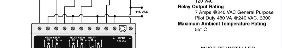
11 External Inputs A five-pin connector is provided for optional external inputs. External Silence / Alarm Reset This input allows for an external NO (Normally Open) pushbutton that will silence audible alarms and clear flashing alarm lights. Pump Inhibit Mode When closed, this will stop all currently running pumps. When it is opened, all necessary pumps will restart with appropriate time delays. Corresponding LEDs will flash when pumps are inhibited. Alarms still function when Inhibit Mode is activated. External Alternation Configuration For Duplex Mode, a SPDT (Single Pole Double Throw) switch can be connected to close RTCL1 or RTCL2 (remote controls) to force Pump 1 or 2 as the Lead Pump. Option Selector Positions 8, 9 & 10 must be OFF. If the switch is in the middle position, pumps will be in alternation mode. For Triplex and Quadplex Modes, two SPST (Single Pole Single Throw) switches can be connected to force Pump 1,2,3 or 4 to be the Lead Pump. Option Selector Positions 9 & 10 must be OFF. To force Pump 1 or 2 as Lead, Position 8 must be OFF. To force Pump 3 or 4 as Lead, Position 8 must be ON. For alternation mode, close both RTCL1 and RTCL2. 3. Wiring Diagrams The following Figures 1-10, show typical wiring diagrams for all pumping modes available for the CB

12 Figure 1. Typical Wiring for Duplex Pump Down - Mode 1 Switch State Mode Selector Switch 1 Time Delay Adjustment MIN. Option Selector Switch 1 High Alarm ON 2 Low Alarm ON 3 Pump 1 ON 4 Pump 2 ON 5 Pump 3 NA 6 Pump 4 NA 7 Fail-Safe OFF 8 ALS-0 ON 9 ALS-1 ON 10 ALS-2 ON Table 6. Typical Duplex Pump Down Setup 11


13 Figure 2. Typical Wiring for Triplex Pump Down - Mode 2 Switch State Mode Selector Switch 2 Time Delay Adjustment MIN. Option Selector Switch 1 High Alarm ON 2 Low Alarm OFF 3 Pump 1 ON 4 Pump 2 ON 5 Pump 3 ON 6 Pump 4 NA 7 Fail-Safe OFF 8 ALS-0 ON 9 ALS-1 ON 10 ALS-2 ON Table 7. Typical Triplex Pump Down Setup 12

14 Figure 3. Typical Wiring for Quadplex Pump Down - Mode 3 Switch State Mode Selector Switch 3 Time Delay Adjustment MIN. Option Selector Switch 1 High Alarm NA 2 Low Alarm NA 3 Pump 1 ON 4 Pump 2 ON 5 Pump 3 ON 6 Pump 4 ON 7 Fail-Safe OFF 8 ALS-0 ON 9 ALS-1 ON 10 ALS-2 ON Table 8. Typical Quadplex Pump Down Setup 13


15 Figure 4. Typical Wiring for Duplex SPS Pump Down - Mode 4 Switch State Mode Selector Switch 4 Time Delay Adjustment MIN. Option Selector Switch 1 High Alarm ON 2 Low Alarm OFF 3 Pump 1 ON 4 Pump 2 ON 5 Pump 3 NA 6 Pump 4 NA 7 Fail-Safe OFF 8 ALS-0 ON 9 ALS-1 ON 10 ALS-2 ON Table 9. Typical Duplex SPS Pump Down Setup 14


16 Figure 5. Typical Wiring for Duplex Pump Up - Mode 5 Switch State Mode Selector Switch 5 Time Delay Adjustment MIN. Option Selector Switch 1 High Alarm ON 2 Low Alarm ON 3 Pump 1 ON 4 Pump 2 ON 5 Pump 3 NA 6 Pump 4 NA 7 Fail-Safe OFF 8 ALS-0 ON 9 ALS-1 ON 10 ALS-2 ON Table 10. Typical Duplex Pump Up Setup 15


17 Figure 6. Typical Wiring for Triplex Pump Up - Mode 6 Switch State Mode Selector Switch 6 Time Delay Adjustment MIN. Option Selector Switch 1 High Alarm OFF 2 Low Alarm ON 3 Pump 1 ON 4 Pump 2 ON 5 Pump 3 ON 6 Pump 4 NA 7 Fail-Safe OFF 8 ALS-0 ON 9 ALS-1 ON 10 ALS-2 ON Table 11. Typical Triplex Pump Up Setup 16


18 Figure 7. Typical Wiring for Quadplex Pump Up - Mode 7 Mode Selector Switch 7 Time Delay Adjustment MIN. Option Selector Switch 1 High Alarm NA 2 Low Alarm NA 3 Pump 1 ON 4 Pump 2 ON 5 Pump 3 ON 6 Pump 4 ON 7 Fail-Safe OFF 8 ALS-0 ON 9 ALS-1 ON 10 ALS-2 ON Table 12. Typical Quadplex Pump Up Setup 17


19 Figure 8. Typical Wiring for Duplex SPS Pump Up - Mode 8 Switch State Mode Selector Switch 8 Time Delay Adjustment MIN. Option Selector Switch 1 High Alarm OFF 2 Low Alarm ON 3 Pump 1 ON 4 Pump 2 ON 5 Pump 3 NA 6 Pump 4 NA 7 Fail-Safe OFF 8 ALS-0 ON 9 ALS-1 ON 10 ALS-2 ON Table 13. Typical Duplex SPS Pump Up Setup 18

20 Figure 9. Typical Wiring for Duplex Pump Down with a Jockey Pump - Mode 1 Switch State Mode Selector Switch 1 Time Delay Adjustment MIN. Option Selector Switch 1 High Alarm ON 2 Low Alarm ON 3 Pump 1 ON 4 Pump 2 ON 5 Pump 3 NA 6 Pump 4 NA 7 Fail-Safe OFF 8 ALS-0 OFF 9 ALS-1 ON 10 ALS-2 OFF Table 14. Typical Duplex Pump Down w/ Jockey Setup 19

21 Figure 10. Typical Wiring for Duplex Pump Down with an Emergency Pump - Mode 1 Switch State Mode Selector Switch 1 Time Delay Adjustment MIN. Option Selector Switch 1 High Alarm ON 2 Low Alarm ON 3 Pump 1 ON 4 Pump 2 ON 5 Pump 3 NA 6 Pump 4 NA 7 Fail-Safe OFF 8 ALS-0 OFF 9 ALS-1 OFF 10 ALS-2 ON Table 15. Typical Duplex Pump Down Setup 20
22 Notes 21
23 4. Five-Channel Relay Mode Some unique features of the Five-Channel Relay mode are described below. To use the CB1000 in this mode, the Mode Selector dial must be set to position 0. Option Selector Position Function Description ON Function OFF Function 1 Enables Channel 2 Latch Channel 1 and 2 function normally Channel 1 Latches Channel 2 2 Enables Channel 4 Latch Channel 3 and 4 function normally Channel 3 Latches Channel 4 3 Relay 1 Logic Positive Negative 4 Relay 2 Logic Positive Negative 5 Relay 3 Logic Positive Negative 6 Relay 4 Logic Positive Negative 7 Relay 5 Logic Positive Negative 8 9 Selects Make/Break Enables Delay-On- Make/Break Timer Delay-On-Break Make/Break Timer Disabled Delay-On-Make Make/Break Timer Enabled 10 Not Used Positive/Negative Logic Table 16. Five-Channel Relay Options Using positive logic will give the same output as input if the input is closed, the corresponding output relay will also be closed. If using negative logic, the output will be the opposite of the input if the input is closed, the output relay will be open. Latched Output Relays 2 and 4 can be configured as latched relays. Input 2 will cause relay 2 to close, but this relay will not open until input 1 opens. Relay 4 will close when input 4 closes, but will not open until input 3 opens. Time Delay Output Relay 5 can be configured as a Delay-On-Make or a Delay-On-Break time delay output. All timing starts when the input switch opens or closes. The time base for this output is adjustable using the Time Delay knob and ranges from seconds. 22


24 Delay-On-Make If Input 5 closes, the time delay will start and LED 5 will flash. Once the time delay has expired, Output Relay 5 will close and the LED will be on. If Input 5 opens at any point during the timing cycle, the time delay stops and Output Relay 5 remains open. Delay-On-Break If Input 5 opens, the time delay will start and LED 5 will flash. Once the time delay has expired, Output Relay 5 will open and the LED will be off. If Input 5 closes at any point during the timing cycle, the time delay stops and Output Relay 5 remains closed. Figure 11. Typical Wiring for 5-channel Relay - Mode 0 23
25 Notes 24
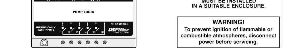
26 Model CB1000 Specifications Control Voltage VAC Frequency 50/60 Hz Power 4 Watts max. Adjustments Time Delay/Lag Pump Delay sec. Mode Selector 0-8 (9-F: force mode 0) Option Selector 1-10 OFF or ON Silence Button Dry Input Only/Non IS Pump Inhibit Dry Input Only/Non IS External Alternation Configuration ALS-1 External Alternation Configuration ALS-2 Pumping Modes Available Duplex Pump Down 2 Pumps w/ High and Low Alarms Triplex Pump Down 3 Pumps w/ High Alarm (typical) Quadplex Pump Down 4 Pumps Duplex Pump Down SPS (Separate Pump Stop) 2 Pumps w/ High Alarm (typical) 2 Stop Floats Duplex Pump Up 2 Pumps w/ High and Low Alarms Triplex Pump Up 3 Pumps w/ Low Alarm (typical) Quadplex Pump Up 4 Pumps Duplex Pump Up SPS (Separate Pump Stop) 2 Pumps w/ Low Alarm (typical) 2 Stop Floats 5-Channel Relay Mode 5-Channel 1 Relay Latched/Time Delay Output Operating Temperature -20 to 55 C Terminals Wire AWG AWG Torque 6 in.-lbs. Relay Contacts B 300 or 240VAC, Pilot Duty 240VAC, 7A max. General Purpose Pump Inrush Delay 2 sec. Entity Parameters Voc=16.8 V I SC =1.7 ma L a =0 C a =0 Provides Intrinsically Safe Circuits in the Following Locations: Standards Passed Class I Groups A, B, C, D Class II Groups E, F, G Class III Electrostatic Discharge (ESD) Radio Frequency Immunity (RFI) Fast Transients IEC , Level 3, 6 kv contact, 8 kv air IEC , Level 3, 10V/m IEC , Level 3, 4 kv input power 2 kv inputs/outputs 25
27 Product Support To obtain technical support or service for USFilter Control Systems products, contact your local USFCS representative. For factory support contact USFilter Control Systems and ask for technical support. Our phone numbers are: Phone: (800) Local: (651) Fax: (651) Our mailing address is: USFilter Control Systems 1239 Willow Lake Blvd Vadnais Heights, MN Product Service For product service outside the warranty, contact your local USFCS representative. For more information on USFCS parts replacement, contact the factory directly at and ask to speak with a customer service representative. 26
28 27
BE SURE POWER IS DISCONNECTED PRIOR TO INSTALLATION! FOLLOW NATIONAL, STATE AND LOCAL CODES. READ THESE INSTRUCTIONS ENTIRELY BEFORE INSTALLATION.
 INSTALLATION INSTRUCTIONS FOR SYMCOM S CONTROL MODEL PC-05 BE SURE POWER IS DISCONNECTED PRIOR TO INSTALLATION! FOLLOW NATIONAL, STATE AND LOCAL CODES. READ THESE INSTRUCTIONS ENTIRELY BEFORE INSTALLATION.!
PumpSaver ISS-105 IS Super Cell Installation Guide
 PumpSaver ISS-105 IS Super Cell Installation Guide Visit our website at www.symcom.com for our complete catalog and new product listings! 2880 North Plaza Drive, Rapid City, South Dakota 57702 (800) 843-8848
Pioneer-R16 Gas Monitor Operator s Manual
 Pioneer-R16 Gas Monitor Operator s Manual Edition 7/2/97 RKI INSTRUMENTS, INC RKI Instruments, Inc. 33248 Central Ave, Union City, CA 94587 (510) 441-5656 Chapter 1: Description About the Pioneer-R16 Gas
Fisher LCP100 Local Control Panel
 Instruction Manual LCP100 Local Control Panel Fisher LCP100 Local Control Panel Contents Introduction... 1 Scope of Manual... 1 Description... 2 Specifications... 2 Installation... 3 Hazardous Area Classifications
4 & 8-POINT ANNUNCIATORS Instruction Manual
 4 & 8-POINT ANNUNCIATORS Instruction Manual 8 Field Selectable Sequences All Common ISA Sequences 4 or 8-Point (Channel) Monitoring Free Replaceable Message Labels Type 4X, NEMA 4X, IP65 Front Universal
Model A1600 Series Annunciator
 Seekirk Model A1600 Series Annunciator Applications: For usage in all types of process industries, electric generation, transmission and distribution, gas and water utilities. Features: The Seekirk model
1S25. Arc Fault Monitor 4 Zones, 8 Sensors. Features. Introduction. ARC Fault Protection
 Technical Bulletin Arc Fault Monitor 4 Zones, 8 Sensors Features Four independent arc fault tripping zones 1 or 2 arc fault sensors per zone allowing up to 8 arc fault sensors per module Trip indication
ESP TECHNOLOGIES LIMITED
 Alarm Technology ESPAN-01 Series Annunciator System Combination type User Manual (Rev. 1) ESP TECHNOLOGIES LIMITED www.esptechno.com Content Page Introduction 2 General Description 2 Overview - Annunciator
D A R A - 4. Data Aire Relay Auto-Changeover
 D A R A - 4 Data Aire Relay Auto-Changeover WARNING: If adding the DARA-4 panel to existing units that did not include a DARA-4 panel when originally purchased it will be necessary to add a relay or relays.
Custom Pump Controls. The Custom Controls Solution Provider. A New Generation. Complete Management. Page 2
 The Custom Controls Solution Provider Hydromatic has a reputation for providing dependable submersible pumps for wastewater lift stations and has continually raised the bar for quality products and customer
ESSEX ENGINEERING CORPORATION
 WATER/WASTEWATER TREATMENT CONTROL SYSTEMS AND SUBSYSTEMS 2000 SERIES CONTROL SYSTEMS: 2000 series are for surface mounting inside a control cabinet Model 2024 Electronic Alternator Duplex (two pump) pump
PD154 & PD158 VIGILANTE II ANNUNCIATORS Instruction Manual
 PD154 & PD158 VIGILANTE II ANNUNCIATORS 8 Field Selectable Sequences All Common ISA Sequences 4 or 8-Point (Channel) Monitoring Free Replaceable Message Labels Type 4X, NEMA 4X, IP65 Front Universal Power
La Marche Manufacturing Company Option 16 Series. Digital Combined Accessory Package. Installation and Operation Manual
 La Marche Manufacturing Company www.lamarchemfg.com Option 16 Series Digital Combined Accessory Package Installation and Operation Manual This manual is subject to change without notice. You may obtain
LC150 VIEW-AT-A-GLANCE PUMP CONTROL-TELEMETRY UNIT
 LC150 VIEW-AT-A-GLANCE PUMP CONTROL-TELEMETRY UNIT Simply Features In Brief Telemetry Ready Security 2 or 3 Pump Control UL Listed Alarm/Event Log Volumetric Flow Calculator VFD Control Optional Dialer
Two-Channel Gas Controller
 Two-Channel Gas Controller Specifications subject to change without notice. USA 09 Page of DESCRIPTION Highly configurable, UL 0 performance-tested and -certified, and wall-mounted gas monitor; continuously
MODEL ZA-8N EIGHT ZONE ANNUNCIATOR FOR ALL MONITORING APPLICATIONS OUTSTANDING FEATURES
 MODEL ZA-8N EIGHT ZONE ANNUNCIATOR FOR ALL MONITORING APPLICATIONS OUTSTANDING FEATURES INDEPENDENT ZONE ANNUNCIATION WITH ZONE STATUS INDICATION EIGHT RED LEDS INDICATE ZONE STATUS SELECTABLE NORMALLY-OPEN,
AO Annunciator Module
 General Specifications GS48C43Z01-00E-N AO-543-01 Annunciator Module GENERAL Figure 1 This module has two independent annunciator circuits. The circuits handle fault signals and operator actions (acknowledge,
INSTRUCTION MANUAL and DETAILED PRODUCT SPECIFICATION TRIPLEX PUMP CONTROL SYSTEM MODEL NUMBER CPC-3. M336 Rev F. November 21, 2000.
 INSTRUCTION MANUAL and DETAILED PRODUCT SPECIFICATION TRIPLEX PUMP CONTROL SYSTEM MODEL NUMBER CPC-3 M336 Rev F November 21, 2000 ÇConsilium Consilium US, Inc. 59 Porter Rd Littleton, MA 01460-1431 USA
Tri-Stack Smart System
 Tri-Stack Smart System TM Notes & Warnings - The protection provided by this equipment may be impaired if it is not used in the manner specified herein. - Ensure all wiring meets applicable national and
RSWT. Three phase AC pumps and ventilators soft starter. Benefits. Description
 Three phase AC pumps and ventilators soft starter Description Benefits Easy to use. The is equipped with a self-learning algorithm that automatically adjusts the start parameters to optimise the motor
TECHNICAL DATA OBSOLETE
 Deluge Devices 270a 1. PRODUCT NAME VIKING PAR-3 Available since 1991 2. MANUFACTURED FOR: THE VIKING CORPORATION 210 N. Industrial Park Road Hastings, Michigan 49058 U.S.A. Telephone: (269) 945-9501 (877)
Installation and Operation Manual
 SENTRY Protect Plus QUADPLEX PANEL Installation and Operation Manual For Hardwired Pumps Environment e Corporation Table of Contents 1 Overview...3 2 Sentry Protect Plus Quadplex Menu Flowchart...4 3 Wiring
La Marche Manufacturing Company Option 46 Series. Digital Combined Accessory Package. Installation and Operation Manual
 La Marche Manufacturing Company www.lamarchemfg.com Option 46 Series Digital Combined Accessory Package Installation and Operation Manual This manual is subject to change without notice. You may obtain
MASTER JOCKEY PUMP CONTROLLER. Model JPCE INSTRUCTION MANUAL. C 2018 Master Control Systems, Inc
 MASTER JOCKEY PUMP CONTROLLER Model JPCE INSTRUCTION MANUAL C 2018 Master Control Systems, Inc TABLE OF CONTENTS Important Safety Information. Page 3 General Description and Installation.. Page 4 Model
Oxygen (O2) Single-Point Gas Detection System
 Single-Point Gas Detection System") Oxygen (O) Single-Point Gas Detection System DESCRIPTION Wall-mounted gas monitor with built-in oxygen (O) sensor, accepts one analog remote device such as a secondary gas sensor, temperature or humidity
Oxygen (O) Single-Point Gas Detection System DESCRIPTION Wall-mounted gas monitor with built-in oxygen (O) sensor, accepts one analog remote device such as a secondary gas sensor, temperature or humidity
Nitrogen Dioxide (NO2) Single-Point Gas Detection System
 Single-Point Gas Detection System") Nitrogen Dioxide (NO) Single-Point Gas Detection System DESCRIPTION Wall-mounted gas monitor with built-in nitrogen dioxide (NO)/diesel fume gas sensor, accepts one analog remote device such as a secondary
Nitrogen Dioxide (NO) Single-Point Gas Detection System DESCRIPTION Wall-mounted gas monitor with built-in nitrogen dioxide (NO)/diesel fume gas sensor, accepts one analog remote device such as a secondary
MASTER PRESSRE MAINTANENCE CONTROLLER. Models PMCE INSTRUCTION MANUAL. C 2018 Master Control Systems, Inc
 MASTER PRESSRE MAINTANENCE CONTROLLER Models PMCE INSTRUCTION MANUAL C 2018 Master Control Systems, Inc TABLE OF CONTENTS Important Safety Information. Page 3 General Description and Installation.. Page
MODEL FPT-130 SINGLE POINT FREEZE PROTECTION HEAT TRACE CONTROL
 TRACON MODEL FPT-130 SINGLE POINT FREEZE PROTECTION HEAT TRACE CONTROL TABLE OF CONTENTS FPT 130 Overview... 2 Installation... 3 Power Source and Load Connections... 4 Temperature Sensor... 5 External
GasScanner 8C. Eight Channel Monitor. Operator s Manual. MINT-0281-XX Rev. A 01/29/08
 GasScanner 8C Eight Channel Monitor Operator s Manual MINT-0281-XX Rev. A 01/29/08 Product Warranty Matheson Tri-Gas, Inc., warrants gas alarm equipment sold by us to be free from defects in materials,
Ç Consilium Consilium US, Inc. 59 Porter Rd Littleton, MA USA
 INSTRUCTION MANUAL and DETAILED PRODUCT SPECIFICATION TRIPLEX BACKUP PUMP CONTROL SYSTEM MODEL NUMBER BPC-3 November 22, 1999 Ç Consilium Consilium US, Inc. 59 Porter Rd Littleton, MA 01460-1431 USA Telephone:
TOTAL SOLUTIONS. Liquid Level Control Product Guide. MATELEC AUSTRALIA innovative by design
 TOTAL SOLUTIONS Liquid Level Control Product Guide MATELEC innovative by design Liquid Level Control Contents Dual Pump Controllers Section 1 The Range Common Features Operating Data Control Logic Setup
STANDARD FEATURES SPECIFICATIONS
 MAG LOCK P/N 300768 STANDARD FEATURES Holding Force: 1500 lbs.(675 Kg.) Easy Installation: Versatile mounting bracket for new and existing doors and frames. Sensor: Built-in Hall effect crystal affected
Pump-Up Controller MODEL 4062
 Pump-Up Controller 4-20mA Input/Scalable Output Seal Fail Monitoring Duplex Pump Alternation Hand-Off-Auto Controls Dual Run-time Meters RS-485/Modbus Communications DESCRIPTION The Model 4062 Pump-Up
GRUNDFOS INSTRUCTIONS LCD 108. Installation and operating instructions
 GRUNDFOS INSTRUCTIONS LCD 08 Installation and operating instructions Installation and operating instructions Original installation and operating instructions CONTENTS Page. Symbols used in this document.
Dual Technology Wall Switch Occupancy Sensor. Manual & Specification
 Dual Technology Wall Switch Occupancy Sensor Manual & Specification PRODUCT MUST BE INSTALLED IN ACCORDANCE WITH LOCAL ELECTRICAL CODES Douglas Lighting Controls Page 1 November 19, 2014 1. INTRODUCTION
VM-702B ABSOLUTE VIBRATION MONITOR MODULE Page 1 of 5
 Page 1 of 5 No entry if additional Model Code / Additional Spec. Code ( spec. code is not specified. ) VM-702B /ALY /NB1 /CS1 /CS2 /TRP /TB Analysis Function Non-incendive * 1 Monitor Function Analysis
Unipower HPL420. User s Manual. True Motor Power Monitor with... Typical Applications. High Trip Alarm. Low Trip Alarm.
 Unipower HPL420 D i g i t a l P o w e r M o n i t o r User s Manual True Motor Power Monitor with... High Trip Alarm Low Trip Alarm Dual Relays Hysteresis Function Analog Output Typical Applications Pumps
Replaceable LED modules. Sleep or unattended mode. Auto-silence and auto-acknowledge
 Replaceable LED modules 11 Alarm Sequences as per ISA-18.1 standard Each channel/window fully field programmable RS232 or RS485 MODBUS-RTU communication Repeat relay for each window and multifunction relays
RANGER 8600 DOWNLOADABLE CONTROL COMMUNICATOR INSTALLATION MANUAL
 RANGER 8600 DOWNLOADABLE CONTROL COMMUNICATOR INSTALLATION MANUAL TABLE OF CONTENTS GENERAL DESCRIPTION... 2 STANDARD AND OPTIONAL PARTS LIST... 2 PARTS DIAGRAM... 3 TERMINAL DRAWING AND SPECIAL NOTES...
TECHNICAL DATA. Humidity: 85% Relative Humidity (non-condensing) at 90 F (32 C) maximum.
 at 90 F (32 C) maximum.") September 29, 1997 Firecycle III 433 a 1. PRODUCT NAME VIKING Model E-1 Manufactured 1997 Present 2. MANUFACTURED FOR THE VIKING CORPORATION 210 N Industrial Park Road Hastings, Michigan 49058, U.S.A.
September 29, 1997 Firecycle III 433 a 1. PRODUCT NAME VIKING Model E-1 Manufactured 1997 Present 2. MANUFACTURED FOR THE VIKING CORPORATION 210 N Industrial Park Road Hastings, Michigan 49058, U.S.A.
ICS Regent. Fire Detector Input Modules PD-6032 (T3419)
") ICS Regent Fire Detector Input Modules (T3419) Issue 1, March, 06 Fire detector input modules provide interfaces for 16 fire detector inputs such as smoke detectors, flame detectors, temperature detectors,
ICS Regent Fire Detector Input Modules (T3419) Issue 1, March, 06 Fire detector input modules provide interfaces for 16 fire detector inputs such as smoke detectors, flame detectors, temperature detectors,
Pump-Down Controller MODEL 4052
 Pump-Down Controller 4-20mA Input/Scalable Output Seal Fail Monitoring Duplex Pump Alternation Hand-Off-Auto Controls Dual Run-time Meters RS-485/Modbus Communications DESCRIPTION The Model 4052 Pump-Down
Features. Omni2 Door Warning Sign Alarm Annunciator DATASHEET. Model C1190B Door Warning Sign
 Features DATASHEET Connects to multiple sensing instruments One/Two Channel Device Bright solid state LED Alarm Display Audible Alert (internal and external) High reliability, fully dual redundant alarm
Alarm Panel Operating Instructions
 Alarm Panel Operating Instructions 1.0 Introduction The Gascon Systems G8850 alarm panel is designed to be used with gas reticulation systems. It is available in single, twin and triple input channel models.
Soft Starter Centrifugal Pump Soft Starter Series
 Soft Starter Centrifugal Pump Soft Starter Series Type RSWT Optimised algorithm for centrifugal pumps Simple User Interface 3-phase controlled Internally bypassed Multi voltage operation Integrated overload
Beacon 800 Gas Monitor Operator s Manual
 Beacon 800 Gas Monitor Operator s Manual Part Number: 71-0037RK Revision: F Released: 4/18/17 www.rkiinstruments.com Product Warranty RKI Instruments, Inc. warrants gas alarm equipment sold by us to be
CM-RQE70 PIR REQUEST TO EXIT DETECTOR
 Door Activation Devices CM-RQE70 PIR REQUEST TO EXIT DETECTOR THIS PACKAGE INCLUDES (1) Wiring Harness (2) #6 x 3/4" Screws (2) 3/16" Wall Plugs (6) Wire Nuts (2) 's BP7175 1. GENERAL DESCRIPTION Camden
Project: Customer: Engineer: Pump Manufacturer: Model GPY + GPU. with Automatic Power Transfer Switch
 Project: Customer: Engineer: Pump Manufacturer: Model GPY + GPU with Automatic Power Transfer Switch Contents: NOTE: The drawings included in this package are for controllers covered under our standard
MODEL GPT-130 SINGLE POINT HEAT TRACE CONTROL THERMOSTAT
 TRACON MODEL GPT-130 SINGLE POINT HEAT TRACE CONTROL THERMOSTAT TABLE OF CONTENTS GPT 130 Overview... 2 Installation... 3 Power Source and Load Connection... 4 Temperature Sensor Installation... 5 Panel
Single Point Freeze Protection Heat Trace Control TRACON MODEL FPT 130 Installation and Operation Manual
 We manage heat MANUAL Single Point Freeze Protection Heat Trace Control TRACON MODEL FPT 130 Installation and Operation Manual 1850 N Sheridan Street South Bend, Indiana 46628 (574) 233-1202 or (800) 234-4239
SECTION AUTOMATIC TRANSFER SWITCHES
 SECTION 26 36 23 AUTOMATIC TRANSFER SWITCHES PART 1 - GENERAL 1.1 RELATED DOCUMENTS A. General provisions of the Contract, including General and Supplementary Conditions and Division 01 Specification Sections,
ModSync Sequencing System Installation & Operation Manual. For use with Fulton Steam Boilers.
 ModSync Sequencing System Installation & Operation Manual For use with Fulton Steam Boilers. Revision 3.0 8/21/2008 - 2 - Table of Contents Introduction Page 4 Features Page 4 Sequence of Operation Page
I/O ZONE 560/583 AND OPERATION MANUAL
 UPM I I/O ZONE 560/583 INSTALLATION AND OPERATION MANUAL 1 UNIT PROTECTION MODULE HARDWARE OPERATION IMPORTANT: This manual is for UPM board part numbers 8733 800 259. See controller label as shown in
Motor Controller AC Semiconductor Motor Controller Type RSBS23..A2V.2C24
 Motor Controller AC Semiconductor Motor Controller Type RSBS23..A2V.2C24 Soft starting of 1-Phase Scroll Compressors Enclosed solution Integrated current limit Rated operational voltage: 230 VACrms, 50/60
DEB71. Earth Leakage Monitoring Relay. Benefits. Description
 Earth Leakage Monitoring Relay Benefits Adjustable trip level. Adjustable leakage threshold from 30mA to 5A or from 300mA to 30A. 2 outputs. Two relay outputs provide, besides the alarm signal an additional
SPECIFICATION CHEMGARD INFRARED GAS MONITOR SERIES
 SPECIFICATION CHEMGARD INFRARED GAS MONITOR SERIES USER INSTRUCTIONS FOR THE CHEMGARD INFRARED GAS MONITOR SERIES To completely customize the specification to your exact application, modification to the
VAMP 120 & 121. Arc flash detection units. Product picture
 Arc flash detection units VAMP 120 and 121(D) are extremely fast arc flash detection units for LV and MV switchgear and controlgear. The units are especially designed to increase the safety and to minimize
MR3CCUHV Temperature/Defrost Control
 Master Catalog 125 Temperature Controls Section A Product/Technical Bulletin Issue Date 0401 MR3CCUHV Temperature/Defrost Control The MR3CCUHV Temperature/Defrost Control is designed to control the temperature
Soft Starter AC Semiconductor Motor Controller Type RSBS23..A2V.2C24..
 Soft Starter AC Semiconductor Motor Controller Type RSBS23..A2V.2C24.. Soft starting of 1-Phase Scroll Compressors Enclosed solution Integrated current limit Rated operational voltage: 230 VACrms, 50/60
7XG3120 ReyArc20 Arc Fault Monitor Relay Energy Management
 Reyrolle Protection Devices 7XG3120 ReyArc20 Arc Fault Monitor Relay Energy Management 7XG3120 - Arc Fault Monitor Relay The over-current caused by an arc is, due to its resistance, lower than the over-current
Crypto-Lock. Model CC-8521B Updated 7/17. Access Control System. MONITEQ, Inc. INSTRUCTION MANUAL
 Crypto-Lock Model CC-8521B Updated 7/17 Access Control System INSTRUCTION MANUAL MONITEQ, Inc. 2 TABLE OF CONTENTS 1. INTRODUCTION..4 2. SPECIFICATIONS.....6 3. SUPPLIED EQUIPMENT.. 6 4. FUNCTIONS OF CONTROLS
enproteko.com Specifications Ratings Item voltage to 24 VAC 5/6 Hz 24 VAC 5/6 Hz or 24 VDC Allowable voltage Characteristics 85% to 11% of power suppl
 enproteko.com Temperature Monitoring Relay K8AB-TH Compact and Slim Relay Ideal for Temperature Alarms and Monitoring Excessive increases can be prevented and abnormal s can be monitored. Temperature monitoring
CM-RQE70A PIR REQUEST TO EXIT DETECTOR
 Door Activation Devices CM-RQE70A PIR REQUEST TO EXIT DETECTOR THIS PACKAGE INCLUDES (2) #6 x 3/4" Screws (2) 3/16" Wall Plugs (2) MOV's BP7175 1. GENERAL DESCRIPTION Camden CM-RQE70A Request-to-Exit Sensor
ANCHOR BOLT DETAIL. Non-Shrink Grout. Poured In Place, After Equipment Setting. "L" Type Anchor Bolt Carbon Steel AISI 304 S.S.
 ANCHOR BOLT DETAIL Heavy Flat Washer Heavy Hex Nut UNC Th'd Mounting Flange Of Equipment To Be Mounted C B A D Non-Shrink Grout. Poured In Place, After Equipment Setting. Heavy Flat Washer Heavy Hex Nut
Model A1700 Series Annunciator
 Seekirk Model A1700 Series Annunciator Applications: For usage in all types of process industries, electric generation, transmission and distribution, gas and water utilities. Features: The Seekirk model
F PC and AO OUTPUT BOARDS INSTRUCTION MANUAL. Blue-White. Industries, Ltd.
 F-2000 PC and AO OUTPUT BOARDS INSTRUCTION MANUAL Blue-White R Industries, Ltd. 500 Business Drive Huntington Beach, CA 92649 USA Phone: 714-89-8529 FAX: 714-894-9492 E mail: sales@blue-white.com or techsupport@blue-white.com
Alarm Tone Generator Model AG17
 Alarm Tone Generator Installation & Operation P005089 Rev. C 150930 9/30/2015 12:25 PM Ph: 403.258.3100 \ email:info@guardiantelecom.com \ www.guardiantelecom.com Table of Contents Package Contents...
705 Emmett Street Bristol, CT DynaLock MODEL 3101C-TJ101 DELAY EGRESS SYSTEM WIRING INSTRUCTIONS
 BASIC SET-UP 1. Remove the Electronics Cover to expose the circuit board assembly. C L C 2. - System Selector Switches The selector switches (S3) which control major system functions are factory set to
Guide Specification Model CTG Automatic Transfer Switch
 Guide Specification Model CTG Automatic Transfer Switch PART 1 GENERAL 1.1 Scope A. It is the intent of this specification to secure a transfer switch that has been prototype tested, factory built, production
EMS510 Electrical Wiring Guide Volume 2, Rev 1.4
 EMS510 Electrical Wiring Guide Volume 2, Rev 1.4 Prepared by Michael L. Kominske Environmental Monitor Service Inc. PO Box 4340 Yalesville, CT 06492 Phone 203.935.0102 Fax 203.634.6663 Email: sales@emsct.com
Instructions for the fan motor control system with integrated wiring terminals SILVER C
 Instructions for the fan motor control system with integrated wiring terminals SILVER C 1. General The motor control system is used for controlling the type EC, 0.41-10 kw fan motors in the SILVER C units.
Engineering Guideline. pac- Carriers Type Universal
 Engineering Guideline pac- Carriers Type 9195 Universal Integration of conventional process automation interfaces pac- Carrier The pac- Carrier reflects the intention of R. STAHL to provide state-of-the-art
Drawing Submittal Package
 Project: Customer: Engineer: Pump Manufacturer: Drawing Submittal Package Model GPL + GLU Limited Service Full Voltage Across the Line Start Electric Pump Controller with Automatic Power Transfer Switch
Motor Controller AC Semiconductor Motor Controller Type RSBS23..A2V.2C24..
 Motor Controller AC Semiconductor Motor Controller Type RSBS23..A2V.2C24.. Soft starting of 1-Phase Scroll Compressors Enclosed solution Integrated current limit Rated operational voltage: 230 VACrms,
Tower & Obstruction Lighting Controls
 Series Included Tower & Obstruction Lighting Controls Beacon Flasher FA....137 FS155-............................................137 FS165-............................................137 Lamp Monitors
CORNELL Emergency Response Systems
 CORNELL Emergency Response Systems Door Monitor Systems Series 1000 CORNELL Communications, Inc. Milwaukee, WI USA 800-558-8957 - www.cornell.com rev 6/04 A-1000 SERIES DOOR MONITOR OPERATION AND WIRING
Soft Start Series MP700 Solid State, Reduced Voltage
 Metron Fire Pump Controls and Accessories Soft Start Series MP700 Solid State, Reduced Voltage Metron Fire Pump Controllers conform to the latest requirements of National Fire Protection Association s
Dual Point General Purpose Heat Trace Control TRACON MODEL GPT 230 Installation and Operation Manual
 We manage heat MANUAL Dual Point General Purpose Heat Trace Control TRACON MODEL GPT 230 Installation and Operation Manual 1850 N Sheridan Street South Bend, Indiana 46628 (574) 233-1202 or (800) 234-4239
Model VPS + VPU Pressure Limiting (VFD) Electric Fire Pump Controller with Soft Start Bypass with Automatic Power Transfer Switch
 Electric Fire Pump Controller with Soft Start Bypass with Automatic Power Transfer Switch") Project: Customer: Engineer: Pump Manufacturer: Technical Data Submittal Document Model VPS + VPU Pressure Limiting (VFD) with Soft Start Bypass with Automatic Transfer Switch Contents: Data Sheets Dimensional
Project: Customer: Engineer: Pump Manufacturer: Technical Data Submittal Document Model VPS + VPU Pressure Limiting (VFD) with Soft Start Bypass with Automatic Transfer Switch Contents: Data Sheets Dimensional
Ion Endeavor Pump Controller Digital Level Control with Pump Alternation and High Water Alarm
 Ion Endeavor Controller Digital Level Control with Alternation Page 1 of 8 General Overview The Ion Endeavor is a pump controller that senses a water level of up to 72", has a configurable water level/pump
DGC-1000 DIGITAL GENSET CONTROLLER
 DGC-1000 DIGITAL GENSET CONTROLLER Basler Electric s Digital Genset Controller (DGC-1000) offers a low cost microprocessor based integrated alternative for small to medium sized genset control and monitoring.
Refer to Bulletin E-1101 for detailed information on the FLAME-MONITOR System.
 The Fireye EP260, EP270 (early spark termination), or EP265 (pilot stabilization) programmer modules are used with the FLAME-MONITOR Burner Management Control System (P/N E110). Several operational characteristics
Technical Data Submittal Document
 Project: Customer: Engineer: Pump Manufacturer: Technical Data Submittal Document Model GPL + GLU Limted Service Full Voltage Across the Line Start Electric Fire Pump Controller Contents: Data Sheets Dimensional
MAINTENANCE & TROUBLESHOOTING GUIDE LEAK ALARM CHANNEL DRY OIL WATER AUX ALARM HIGH LOW CRITICAL WATER TANK LEVEL ALARM MODEL LDE-740 ADVANCE PAPER
 PNEUMERCATOR Liquid Level Control Systems Electronic Systems Excluding LC2000 And TMS Series MAINTENANCE & TROUBLESHOOTING GUIDE 400 300 500 FUEL LEVEL LEAK MONITOR 1 200 600 OIL/GAS NORMAL WATER PNEUMERCATOR
Analog Room Pressure Monitor RPC Series
 Description The Room Pressure Monitor is used to measure differential pressure in the range of 0.125 to 1"wc or 30 to 250 Pa. It combines precision high sensitivity silicon sensing capabilities and the
GM420. Digital Ground Continuity Relay For AC Systems. Technical Bulletin NAE /
 3 GM20 Digital Ground Continuity Relay For AC Systems Technical Bulletin NAE03230 / 0.20 GM20 Ground continuity monitor For AC systems Description The GM20 monitors the loop resistance of ground conductors
PRYCO, INC. FUEL CONTROL
 PRYCO, INC. FUEL CONTROL and MONITORING SYSTEM Page 1 DETAIL SPECIFICATIONS INTRODUCTION PRYCO s FUEL CONTROL and MONITORING (FCM) system is the most sophisticated and powerful control tool available for
HOKKIM INTEGRATED AMF CONTROL BOARD MANUAL FOR MODELS: HAMF-8 AND HAMF-4
 HOKKIM INTEGRATED AMF CONTROL BOARD MANUAL FOR MODELS: HAMF-8 AND HAMF-4 INTRODUCTION Thank you for purchasing the Hokkim Integrated Automatic Mains Failure Control Board model HAMF- 8 or HAMF-4. We shall
! WARNING To avoid risk of electrical shock, personal injury or death; disconnect power to range before servicing, unless testing requires power.
 Technical Information Electric Slide-In Range JES8850BC* JES9900BC* JES9860BC* Due to possibility of personal injury or property damage, always contact an authorized technician for servicing or repair
1025, BOUL. MARCEL-LAURIN INSTRUCTION MANUAL FOR WATER COOLED ENVIROCHILL CHILLER. Prepared par Claude Gadoury, P. Eng MTL TECHNOLOGIES INC.
 WYETH-AYERST CANADA INC. 1025, BOUL. MARCEL-LAURIN S T - L A U R E N T, Q U É B E C INSTRUCTION MANUAL FOR WATER COOLED ENVIROCHILL CHILLER MODEL P448800LT--55WC--22C66S Prepared par Claude Gadoury, P.
M2500 Engine Controller Installation Manual
 M2500 Engine Controller Installation Manual Revision: 23-04-2012 Page 1 Contents 1 Preface... 4 2 Installation... 5 3 Terminal Connections... 6 4 Inputs... 7 4.1 Power Supply... 7 4.2 Mode/ Control Inputs...
Operating & Maintenance Manual. Alert-4 Ethernet LCD Master Alarm
 Operating & Maintenance Manual Alert-4 Ethernet LCD Master Alarm w w w. a m i c o. c o m Contents User Responsibility 4 Introduction 4 Features 5 Description of the Alarm 5 Shipment Details 5 The Alarm
21-light Remote Annunciator. Owner s Manual
 21-light Remote Annunciator Owner s Manual Annunciator Description... Inside Font Cover Detailed Specifications... 1 Environmental Specifications... 1 Power Supply Requirements... 1 Communication With
Drawing Submittal Package
 Project: Customer: Engineer: Pump Manufacturer: Drawing Submittal Package Model GPL + GLU Limited Service Full Voltage Across the Line Start Electric Pump Controller with Automatic Power Transfer Switch
MBCE-110/230UV Flame Sensor Module
 MBCE-1002 FEBRUARY 3, 2017 MBCE-110/230UV Flame Sensor Module DESCRIPTION The MBCE-110/230UV modules provide visual indication and electrical outputs that signal the user regarding flame presence in a
Toxic and Explosive Smart Gas Monitor PN / Installation and User Manual
 Toxic and Explosive Smart Gas Monitor PN 151022/151023 Installation and User Manual Quest Controls, Inc. 208 9 th Street Dr. West Palmetto, FL 34221 www.questcontrols.com Phone: (941) 729-4799 Fax: (941)
EXTINGUISHING AGENT RELEASE MODULE
 EXTINGUISHING AGENT RELEASE MODULE Operation, Installation & Programming Manual Revision 3.00 Distributors For: 18-20 Brookhollow Ave telephone 02 8850 2888 www.firesense.com.au Baulkham Hills NSW 2153
MBCE-110/230FR Flame Sensor Module
 MBCE-1001 FEBRAURY 6, 2017 MBCE-110/230FR Flame Sensor Module exida FMEDA SIL2 SEE NOTE 1 ON PAGE 4 DESCRIPTION The MBCE-110/230FR modules provide visual indication and electrical outputs that signal the
Dual Technology Wall Mounted Occupancy Sensor. Manual & Specification
 Dual Technology Wall Mounted Occupancy Sensor Manual & Specification PRODUCT MUST BE INSTALLED IN ACCORDANCE WITH LOCAL ELECTRICAL CODES Douglas Lighting Controls Page 1 December 16, 2013 1. INTRODUCTION
Model 9010 and 9020 Monitoring Systems
 Model 9010 and 9020 Monitoring Systems Instruction Manual " WARNING THIS MANUAL MUST BE CAREFULLY READ BY ALL INDIVIDUALS WHO HAVE OR WILL HAVE THE RESPONSIBILITY FOR USING OR SERVICING THE PRODUCT. Like