E3 Series Expandable Emergency Evacuation Installation/Operating Manual. Document: Print Date: 6/6/07 Rev: C
|
|
|
- Lauren Owen
- 5 years ago
- Views:
Transcription


1 E3 Series Expandable Emergency Evacuation Installation/Operating Manual Document: Print Date: 6/6/07 Rev: C P/N: ECN: Copyright 2005 Honeywell International Inc. All Rights Reserved Published in U.S.A. 12 Clintonville Road, Northford, CT USA TEL: (203) FAX: (203)
2 Fire Alarm System Limitations While a fire alarm system may lower insurance rates, it is not a substitute for fire insurance! This manual is designed for use by factory-trained installers and operators of the Gamewell-FCI, E3 Series, Expandable Emergency Evacuation, Fire Alarm Control. All illustrations, functional descriptions, operating and installation procedures, and other relevant information are contained in this manual. The contents of this manual are important, and the manual must be kept with the fire alarm control panel at all times. If building ownership is changed, this manual, including any testing and maintenance information, must be passed along to the new owner(s). The fire alarm control panel is part of a system. Manuals and instructions for other devices forming part of the system should be kept together. Purchasers who install this system for use by others must leave the instructions with the user. A copy of these instructions is included with each product and is available from the manufacturer. This equipment is Listed by various listing agencies for use in fire alarm systems. Use only components which are compatible with the Gamewell-FCI system. The installation MUST be in accordance with the instructions in this manual. THEREFORE: DO NOT deviate from the procedures described in this manual. DO NOT assume any details not shown in the instructions. DO NOT modify any electrical or mechanical features. DO comply with all codes and standards set forth by the Authority Having Jurisdiction. The term Authority Having Jurisdiction has become a standard term in the fire alarm industry. An acceptable definition of Authority Having Jurisdiction is: Fire alarm systems installed in the USA fall under the jurisdiction of some authority. In some areas, this may be a local fire department; in other areas, it may be a building inspector, insurance firm, etc. Different authorities may have their own local requirements for the way the fire alarm system is installed and used. Most local authorities base their requirements on the National Fire Protection Agency (NFPA) codes, but there may be important differences. You must install this system in the way in which the Authority Having Jurisdiction requires. If you do not know, which authority has jurisdiction in your area, contact your local fire department or building inspector for guidance. It is important that you tell users to be aware of any requirements defined by the Authority Having Jurisdiction. E3 Series is a trademark of Honeywell International Inc. i The installation MUST be in accordance with the following standards: National Fire Alarm Code (NFPA 72) National Electrical Code (NFPA 70) Life Safety Code (NFPA 101) NFPA 92A Recommended Practice for Smoke Control Systems WARNING: Touching components which are improperly installed, applied or operated could be hazardous and possibly fatal. Short circuits could cause arcing that could result in molten metal injuries. Therefore, only qualified technicians familiar with electrical hazards should perform checkout procedures. Safety glasses should be worn, and test equipment used for voltage measurements should be designed for this purpose and be in good working order. ENVIRONMENTAL CONSIDERATIONS: It is important that this equipment be operated within its specifications: Recommended operating 60 to 80 F temperature range: (15 to 27 C) Absolute maximum operating 32 to 120 F temperature range: (0 to 49 C) Operating humidity: Not to exceed 93% Non-condensing at 90 F (32 C) Operating this equipment within the recommended temperature range will extend the useful life of the system standby batteries. INSTALLATION CONSIDERATIONS: Check that you have all of the equipment you need to make the installation. Follow the field wiring diagrams and installation notes in this manual. Install the equipment in a clean, dry environment (minimal dust). Avoid installing equipment where vibrations will occur. Remove all electronic assemblies prior to drilling, filing, reaming, or punching the enclosure. When possible, make all cable entries from the sides; being careful to separate the power-limited conductors from the non power-limited conductors. Before making modifications, verify that they will not interfere with battery, transformer, and printed circuit board location. Do not over-tighten screw terminals. Over-tightening may damage threads, resulting in reduced terminal contact pressure and difficulty with screw terminal removal. Disconnect all sources of power before servicing, removing, or inserting any circuit boards.
3 Control unit and associated equipment may be damaged by removing WIRING CONSIDERATIONS: This fire alarm control panel contains power-limited circuits. You cannot connect external sources of power to these circuits without invalidating their approval. Verify that wire sizes are adequate for all initiating device and notification appliance circuits. Most devices cannot tolerate more than a 10% drop from the specified device voltage. The installer must make sure that the wiring and devices installed in the system meet the current National Electrical Code, NFPA 70, and all applicable state and local building code requirements. Use the conductor size and type required by local codes. (See NFPA 70, Article 760). Wiring resistance must not be more than that shown on the field wiring diagrams. To reduce errors and help in servicing the system, all conductors should be tagged or otherwise coded and logged at installation to identify circuit assignment and polarity. If the conductors are logged with a code, keep the log that explains the code with the manual, so that it is available to other people working on the panel. Like all solid-state electronic devices, this system may operate erratically or be damaged when subjected to lightening induced transients. Although no system is completely immune to lightening transients and interference, proper grounding will reduce susceptibility. We do not recommend the use of overhead or outside aerial wiring due to the increased susceptibility to nearby lightening strikes. Consult with the Gamewell-FCI Technical Support Department if any problems are anticipated or encountered. To prevent the spread of fire, use proper patching materials to areas where system wiring passes through the fire-rated walls or floors. SURVIVABILITY Per the National Fire Alarm Code, NFPA 72, all circuits necessary for the operation of the notification appliances shall be protected until they enter the evacuation signaling zone that they serve. Any of the following methods shall be considered acceptable as meeting these requirements: 1) A 2-hour rated cable or cable system 2) A 2-hour rated enclosure 3) Performance alternatives approved by Authority Having Jurisdiction MAINTENANCE To keep your fire alarm system in excellent working order, ongoing maintenance is required per the manufacturer s recommendations and UL and NFPA Standards, and applicable state and local codes. At a minimum, the requirements of Chapter 7 of NFPA, the National Fire Alarm Code, shall be followed. A preventative maintenance agreement should be arranged through the manufacturer s local representative. Though smoke detectors are designed for long life, they may fail at any time. Any smoke detector, fire alarm system, or any component of that system shall be repaired or replaced immediately. OTHER CONSIDERATIONS The equipment was tested according to EC directive 89/336/EEC for Class A equipment and was verified to the limits and methods of EN An automatic fire alarm system typically made up of smoke detectors, heat detectors, manual pull stations, audible warning devices, and a fire alarm control panel with remote notification capability-can provide early warning of a developing fire. Such a system, however, does not assure protection against property damage or loss of life resulting from a fire. The Manufacturer recommends that smoke and/or heat detectors be located throughout a protected premise following the recommendations of the current edition of the National Fire Protection Association Standard (NFPA ). The Manufacturer recommends it must also follow State and local codes, and the recommendations contained in the Guide for Proper Use of System Smoke Detectors, (which is made available at no charge to all installing dealers). A study by the Federal Emergency Management Agency (an agency of the United States government) indicated that smoke detectors may not go off in as many as 35% of all fires. While fire alarm systems are designed to provide early warning against fire, they do not guarantee warning or protection against fire. A fire alarm system may not provide timely or adequate warning, or simply may not function, for a variety of reasons: Smoke detectors may not sense fire where smoke cannot reach the detectors such as in chimneys, in or behind walls, on roofs, or on the other side of closed doors. Smoke detectors also may not sense a fire on another level or floor of a building. A second-floor detector, for example, may not sense a first-floor or basement fire. Particles of combustion or smoke from a developing fire may not reach the sensing chambers of smoke detectors because: Barriers such as closed or partially closed doors, walls, or chimneys may inhibit particle or smoke flow. Smoke particles may become cold, stratify, and not reach the ceiling or upper walls where detectors are located. Smoke particles may be blown away from detectors by air outlets. Smoke particles may be drawn into air returns before reaching the detector. The amount of smoke present may be insufficient to alarm smoke detectors. Smoke detectors are designed to alarm at various levels of smoke density. If such density levels are not created by a developing fire at the location of detectors, the detectors will not go into alarm. ii
4 Smoke detectors, even when working properly, have sensing limitations. Detectors that have photoelectronic sensing chambers tend to detect smoldering fires better than flaming fires, which have little visible smoke. Detectors that have ionizing-type sensing chambers tend to detect fastflaming fires better than smoldering fires. Because fires develop in different ways and are often unpredictable in their growth, neither type of detector is necessarily best and a given type of detector may not provide adequate warning of a fire. Smoke detectors cannot be expected to provide adequate warning of fires caused by arson, children playing with matches (especially in bedrooms), smoking in bed, and violent explosions (caused by escaping gas, improper storage of flammable materials, etc.). Heat detectors do not sense particles of combustion and alarm only when heat on their sensors increases at a predetermined rate or reaches a predetermined level. Rate-of-rise heat detectors may be subject to reduced sensitivity over time. For this reason, the rate-of-rise feature of each detector should be tested at least once per year by a qualified fire protection specialist. Heat detectors are designed to protect property, not life. IMPORTANT! Smoke detectors must be installed in the same room as the control panel and in rooms used by the system for the connection of alarm transmission wiring, communications, signaling, and/or power. If detectors are not so located, a developing fire may damage the alarm system, crippling its ability to report a fire. Audible warning devices such as bells may not alert people if these devices are located on the other side of closed or partly open doors or are located on another floor of a building. Any warning device may fail to alert people with a disability or those who have recently consumed drugs, alcohol, or medication. Please note that: Strobes can, under certain circumstances, cause seizures in people with conditions such as epilepsy. Studies have shown that certain people, even when they hear a fire alarm signal, do not respond or comprehend the meaning of the signal. It is the property owner's responsibility to conduct fire drills and other training exercise to make people aware of fire alarm signals and instruct them on the proper reaction to alarm signals. In rare instances, the sounding of a warning device can cause temporary or permanent hearing loss. A fire alarm system will not operate without any electrical power. If AC power fails, the system will operate from standby batteries only for a specified time and only if the batteries have been properly maintained and replaced regularly. Equipment used in the system may not be technically compatible with the control panel. It is essential to use only equipment listed for service with your control panel. Telephone lines needed to transmit alarm signals from a premise to a central monitoring station may be out of service or temporarily disabled. For added protection against telephone line failure, backup radio transmission systems are recommended. The most common cause of fire alarm malfunction is inadequate maintenance. To keep the entire fire alarm system in excellent working order, ongoing maintenance is required per the manufacturer's recommendations, and UL and NFPA standards. At a minimum, the requirements of NFPA shall be followed. Environments with large amounts of dust, dirt or high air velocity require more frequent maintenance. A maintenance agreement should be arranged through the local manufacturer's representative. Maintenance should be scheduled monthly or as required by National and/or local fire codes and should be performed by authorized professional fire alarm installers only. Adequate written records of all inspections should be kept. While installing a fire alarm system may make the owner eligible for a lower insurance rate, a fire alarm system is not a substitute for insurance. Property owners should continue to act prudently in protecting the premises and the people in the premises and should properly insure life and property and buy sufficient amounts of liability insurance to meet their needs. Limit-C iii
5 Installation Precautions Adherence to the following will aid in problem-free installation with long-term reliability: WARNING - Several different sources of power can be connected to the fire alarm control panel. Disconnect all sources of power before servicing. Control unit and associated equipment may be damaged by removing and/or inserting cards, modules, or interconnecting cables while the unit is energized. Do not attempt to install, service, or operate this unit until manuals are read and understood. CAUTION - System Re-acceptance Test after Software Changes: To ensure proper system operation, this product must be tested in accordance with NFPA 72 after any programming operation or change in site-specific software. Re-acceptance testing is required after any change, addition, or deletion of system components, or after any modification, repair, or adjustment to system hardware or wiring. All components, circuits, system operations, or software functions known to be affected by a change must be 100% tested. In addition, to ensure that other operations are not inadvertently affected, at least 10% of initiating devices that are not directly affected by the change, up to a maximum of 50 devices, must also be tested and proper system operation verified. Equipment used in the system may not be technically compatible with the control panel. It is essential to use only equipment Listed for service with this control panel. This system meets UL requirements for operation at 0-49º C/32-120º F and at a relative humidity (non condensing) of 85% at 30 C (86 F) per NFPA, and 93% ± 2% at 32 C ± 2 C (89.6 F ± 1.1 F) per UL 93% ± 2% RH (non-condensing) at 32 C ± 2 C (90 F ± 3 F). However, the useful life of the system's standby batteries and the electronic components may be adversely affected by extreme temperature ranges and humidity. Therefore, it is recommended that this system and its peripherals be installed in an environment with a normal room temperature of 15-27º C/60-80º F. Verify that wire sizes are adequate for all initiating and indicating device loops. Most devices cannot tolerate more than a 10% I.R. drop from the specified device voltage. Like all solid-state electronic devices, this system may operate erratically or can be damaged when subjected to lightening induced transients. Although no system is completely immune from lightening transients and interference, proper grounding will reduce susceptibility. Overhead or outside aerial wiring is not recommended, due to an increased susceptibility to nearby lightening strikes. Consult with the Technical Services Department if any problems are anticipated or encountered. Disconnect AC power and batteries prior to removing or inserting circuit boards. Failure to do so can damage circuits. Remove all electronic assemblies prior to any drilling, filing, reaming, or punching of the enclosure. When possible, make all cable entries from the sides or rear. Before making modifications, verify that they will not interfere with battery, transformer, or printed circuit board location. Do not tighten screw terminals more than 9 in-lbs. Over-tightening may damage threads, resulting in reduced terminal contact pressure and difficulty with screw terminal removal. This system contains static-sensitive components. Always ground yourself with a proper wrist strap before handling any circuits so that static charges are removed from the body. Use static suppressive packaging to protect electronic assemblies removed from the unit. Follow the instructions in the installation, operating, and programming manuals. These instructions must be followed to avoid damage to the control panel and associated equipment. FACP operation and reliability depend upon proper installation. Precau-D FCC Warning: This equipment generates, uses, and can radiate radio frequency energy and, if not installed and used in accordance with the instruction manual, may cause interference to radio communications. It has been tested and found to comply with the limits for Class A computing device pursuant to Subpart B of Part 15 of FCC Rules, which is designed to provide reasonable protection against such interference when operated in a commercial environment. Operation of this equipment in a residential area is likely to cause interference, in which case the user will be required to correct the interference at the user s expense. If these instructions are not clear, or if additional information or clarification is needed, please consult your local authorized Gamewell-FCI distributor. Because of design changes and product improvements, the information in this manual is subject to change without notice. Gamewell-FCI reserves the right to change hardware and/or software design, which may subsequently affect the contents of this manual. Gamewell-FCI assumes no responsibility for any errors that may appear in this manual. Neither this manual nor any part of it may be reproduced without the advance written permission of Gamewell-FCI. iv
6 Documentation Feedback Your feedback helps us keep our documentation up-to-date and accurate. If you have any comments or suggestions about our online Help or printed manuals, you can us. Please include the following information: Product name and version number (if applicable) Printed manual or online Help Topic Title (for online Help) Page number (for printed manual) Brief description of content you think should be improved or corrected Your suggestion for how to correct/improve documentation Send messages to: Please note this address is for documentation feedback only. If you have any technical issues, please contact Technical Services. v
7 Table of Contents Table of Contents System Overview Description Features Standard Features Optional Features System Components Control and Indicator Sub-Assembly (LCD-E3) Intelligent Loop Interface - Main Board (ILI-MB-E3) Power Supply - 9 Amperes (PM-9) Optional Modules Addressable Switch Sub-Assembly (ASM-16) Digital Alarm Communicator Transmitter (DACT-E3) Repeater (RPT-E3) Intelligent Loop Interface Expansion Board (ILI-S-E3) Remote LED Driver (ANU-48) LCD Network Graphic Annunciator (NGA) Remote LCD Display (LCD-7100) Intelligent Network Interface Voice Gateway (INI-VG) Watt Amplifier (AM-50) Specifications Power Supply (PM-9) Signaling Line Circuits (ILI-MB-E3) Notification Appliance Circuits (ILI-MB-E3) Alarm Dry Contacts (ILI-MB-E3) Trouble Dry Contacts (ILI-MB-E3) Supervisory Dry Contacts (ILI-MB-E3) Earth Ground Connection (ILI-MB-E3) VDC Power, System (ILI-MB-E3) RS-232 Port Battery Connection (PM-9) City Master Box Output Remote Signaling Output (Polarity Reversal) Installation General Location Unpacking Mounting Sub-assemblies Cabinets Cabinet A1, Installation Instructions Cabinet A1, Backbox Installation Cabinet A1, Outer Door Installation Cabinet A1, Inner Door to the Backbox Installation Cabinet A1, Inner Door Installation Cabinet A2, Installation Instructions Cabinet A2, Backbox Installation Cabinet A2, Outer Door Installation Cabinet A2, Inner Door to the Backbox Installation Cabinet A2, Inner Door Installation Cabinet A, 2-Bay Installation Instructions Cabinet A, 2-Bay and 3-Bay Backbox Installation Cabinet A, 2-Bay and 3-Bay Outer Door Installation Cabinet A, 2-Bay Inner Door to the Backbox Installation Page 1 of 94
8 Cabinet A, 2-Bay, Inner Door Installation Cabinet A, 3-Bay Installation Instructions Cabinet A, 3-Bay, Inner Door to the Backbox Installation Cabinet A, 3-Bay, Inner Door Installation Cabinet B Installation Instructions Cabinet B, Backbox Installation Cabinet B, Outer Door Installation Cabinet B, Backbox Sub-Assembly Installation (Typical) Cabinet B, Inner Door to the Backbox Installation Cabinet B, Inner Door Installation Cabinet C, INX-E3 Installation Instructions Cabinet C, Backbox Installation Cabinet C, INX-E3, Outer Door Installation Cabinet C, INX-E3, Sub-Assembly Plate Installation Cabinet C, INX-E3, Sub-Assembly Plate to the Backbox Installation Cabinet C, INCC-E3 Installation Instructions Cabinet C, INCC-E3, Outer Door Installation Cabinet C, INCC-E3, Sub-Assembly Plate Installation Cabinet C, INCC-E3, Sub-Assembly Plate to the Backbox Installation Cabinet C, INCC-E3, 7-Bay Inner Door to the Backbox Installation Cabinet C, INCC-E3, 7-Bay Inner Door Installation Cabinet C, INCC-E3, 8-Bay Inner Door to the Backbox Installation Cabinet C, INCC-E3, 8-Bay Inner Door Installation Cabinet D Installation Instructions Cabinet D, Backbox Installation Cabinet D, Outer Door Installation Cabinet D, Sub-Assembly to the Backbox Installation Cabinet D, 13-Bay Inner Door to the Backbox Installation Cabinet D, 13-Bay Inner Door Installation Cabinet D, 14-Bay Inner Door to the Backbox Installation Cabinet D, 14-Bay Inner Door Installation System Connections Intelligent Loop Interface-Main Board Sub-Assembly (ILI-MB-E3) Table 3-1 ILI-MB-E3 Field Wiring Connections Auxiliary Power Output, Resettable/Non-resettable Relay Connections Signaling Line Circuits Notification Appliance Circuits INI-7100 Addresses Table 3-2 INI-7100 Addresses Power Supply (PM-9) Table 3-3 PM-9 Terminals, Jumpers & LEDs PM-9 AC Power Connection Battery Connections (PM-9) Specifications Addressable Switch Sub-Assembly (ASM-16) (Optional) ASM-16 Wiring Connections Table 3-4 ASM-16 or ANU-48 Wiring Connections Specifications Digital Alarm Communicator Transmitter (DACT-E3) (Optional) Central Station Reporting Table 3-5 UL Listed Receivers Compatible with the E3 Series DACT-E3 Event Reporting Codes Table 3-6 DACT-E3 Event Reporting Codes* Telephone Requirements Table 3-7 DACT-E3 Wiring Connections Page 2 of 94
9 3.4.4 Specifications Repeater Sub-Assembly (RPT-E3) (Optional) RPT-E3-FO RPT-E3-UTP Table 3-8 Repeater-E3 Wiring Connections Specifications Intelligent Loop Interface Expansion Board (ILI-S-E3) (Optional) ILI-S-E3 Wiring Connections Table 3-9 ILI-S-E3 Field Wiring Connections Specifications Remote LED Driver Sub-Assembly (ANU-48) (Optional) ANU-48 Wiring Connections Table 3-10 ANU-48 Wiring Connections ANU-48 DIP Switch Addresses Specifications Panel Display LCD-E Table 3-11 LCD-E3 Field Wiring Connections Address Specifications Remote Display Sub-Assembly (LCD-7100) (Optional) Address Specifications Mounting Standby Battery Calculations Table 3-12 Battery Standby Chart Analog Sensors Address Switches Drift Compensation Addressable Modules Monitor Modules Control Modules Address Switches Programming/Operation Instructions LED Indicators (LCD-E3) Table 4-1 LED Indicators Switches (LCD-E3) Table 4-2 Switches Programming MAIN LCD-E3 Menu Selections WALK / DRILL Menu Selection I/O Menu Selection CLOCK Menu Selection MISC Menu Selection LOG Menu Selection INFO Menu Selection Power Up Procedure General To Set the System Time Automatic Configuration Test and Maintenance Test Maintenance Power-Limited Non Power-Limited Wiring Page 3 of 94
10 1.0 System Overview 1.1 Description The Gamewell-FCI E3 Series Expandable Emergency Evacuation System is a multiprocessor-based analog/addressable fire alarm control panel, designed for commercial, industrial and institutional fire alarm applications. The E3 Series is Listed by Underwriter s Laboratories under Standard UL 864, 9 th Edition. It is suitable for the following signaling services: Automatic Fire Detector Alarm Manual Fire Alarm Waterflow Alarm Supervisory Automatic Smoke Alarm, non-coded and master coded operation When configured and installed under the supervision of a Gamewell-FCI factory trained and certified distributor, the E3 Series complies with the requirements of the following National Fire Protection Association (NFPA) Standards: NFPA 13 NFPA 72 Installation of Sprinkler Systems National Fire Alarm Code: - Central Station Fire Alarm Systems - Local Fire Alarm Systems - Auxiliary Fire Alarm Systems - Remote Station Fire Alarm Systems - Proprietary Fire Alarm Systems 1.2 Features Standard Features Two (2), Class A, Style 6, 7* or Class B, Style 4 Signaling Line Circuits Two (2), Class A, Style Z or Class B, Style Y Notification Appliance Circuits, 2.0 amp each Alarm, Trouble and Supervisory dry contacts Accommodates 159 Gamewell-FCI Approved, UL Listed compatible analog sensors per signaling line circuit. Accommodates 159 Gamewell-FCI Approved, UL Listed compatible addressable monitor/control devices per signaling line circuit. 80-character alphanumeric LCD display (40 characters user-defined) 4100 event history buffer (non-volatile) Power-limited Resettable/non-resettable VDC power output each Alarm verification Walk test Multi-level alarm processing Positive Alarm Sequence (PAS) operation NAC coding Trouble reminder Integral RS-232 port *Style 7 operation requires System Sensor M500X Isolator Modules. Page 4 of 94
11 1.2.2 Optional Features Remotable DACT-E3 Digital Alarm Communicator Transmitter RPT-E3 ARCNET Repeater Remotable ANU-48 Remote LED Driver Remotable ASM-16 Addressable Switch Sub-assembly Remotable NGA Network Graphic Display LCD-7100 Remote LCD Display 1.3 System Components Control and Indicator Sub-Assembly (LCD-E3) The LCD-E3 provides an LCD display for system status, and the following Switches and LED indicators: Alarm Acknowledge Trouble Acknowledge Signal Silence System Reset/Lamp test Programming buttons Menu/Back Back Space/Edit OK 12 button keypad LED Indicators AC Power On (green) Power Fault (yellow) Alarm (red) Ground Fault (yellow) Supervisory (yellow) System Silenced (yellow) System Trouble (yellow) Figure Switch Control Panel The ILI-MB-E3 can support up to six (6), LCD-E3 sub-assemblies, any or all of which may be remotely located via the local RS-485 serial interface Intelligent Loop Interface - Main Board (ILI-MB-E3) The ILI-MB-E3 is the main operating sub-assembly for the E3 control. It provides two (2), signaling line circuits and terminals for the connection of all subassemblies. This unit can support an LCD-E3, DACT-E3 and up to a total of sixteen (16), ASM-16 and/or ANU-48 sub-assemblies. It occupies one node on the Broadband network. Alarm signals lock-in. Supervisory and Trouble signals do not lock-in. Municipal Connection - The ILI-MB-E3 provides output for a local energy City Master Box which is non power-limited. Audible Sounder - An Alarm/Trouble/Supervisory sounder is located on the ILI-MB-E Power Supply - 9 Amperes (PM-9) The PM-9 is a 9 ampere regulated power supply with a battery charger that provides operating power to the panel. The battery charger can maintain batteries up to 55 A/H. (Batteries not furnished). Page 5 of 94
12 1.4 Optional Modules The following optional sub-assemblies and features are available: Addressable Switch Sub-Assembly (ASM-16) The ASM-16 is a configurable switch input sub-assembly with 16 switches and 48 status LEDs and may be remotely located via the RS-485 serial interface. Each switch address is fully software programmable to serve as: A System Control Switch; Reset, Silence, Alarm and Trouble Acknowledge, etc. A Voice Evacuation Speaker Circuit control switch A Fire Fighter Communication Circuit control switch An Auxiliary Control Circuit switch A status indicating LED, red, green, and yellow A status indicating LED, labeled to indicate Command Center in Control Digital Alarm Communicator Transmitter (DACT-E3) The DACT-E3 provides an integral, remotable Digital Alarm Communicator Transmitter (DACT), fully programmable from the keypad, which is compatible with Digital Alarm Communicator Receivers (DACRs) that can receive the following formats: SIA DC8 SIA DCS20 Ademco Contact ID Hz Hz Hz Hz The DACT-E3 can be remotely located via the local RS-485 serial interface Repeater (RPT-E3) The RPT-E3 sub-assembly provides remote interface between the ILI-MB-E3 and the Broadband Network. It can also be used with the NGA. The unit can be used with unshielded, twisted-pair wire or fiber-optic cable as the Model (RPT- E3-FO). The Model (RPT-E3-UTP) is used with twisted-pair only Intelligent Loop Interface Expansion Board (ILI-S-E3) The ILI-S-E3 sub-assembly provides additional two (2), signaling line circuits only. It is physically identical to the ILI-MB-E3 except components are omitted. It occupies one node on the Broadband network Remote LED Driver (ANU-48) The ANU-48 LED Driver provides output for up to forty-eight (48), remote LEDs. The ILI-MB-E3 will support up to a total of sixteen (16), ANU-48 and/or ASM-16 units. The ANU-48 can be remotely located via the RS-485 serial interface LCD Network Graphic Annunciator (NGA) The NGA mounts in the E3 Series enclosure or it may be remotely located. It provides an LCD display of system events, together with system status indicating LEDs and touch-screen switches for Alarm Acknowledge, Trouble Acknowledge, Signal Silence and System Reset. The NGA occupies one node on the Broadband network. The background display can be programmed to state, Command Center in Control if desired. Page 6 of 94
13 1.4.7 Remote LCD Display (LCD-7100) The LCD-7100 Remote LCD Display provides an 80-character display and function keys for Alarm Acknowledge, Trouble Acknowledge, Signal Silence, System Reset/Lamp Test and System Drill Test. It features a key switch that renders the key pad inoperative until activated. The E3 Series System can support up to five (5), LCD-7100 displays. The 80-character display shows all pertinent information except for menus Intelligent Network Interface Voice Gateway (INI-VG) The INI-VG Voice Gateway provides a network interface for the E3 Series, Expandable Emergency Evacuation System. The INI-VGC-FO or INI-VGC-UTP is used in conjunction with the Voice Evacuation Command Center (INCC-C). The INI-VGX-FO or INI-VGX-UTP is used with the E3 Series Broadband, and the INI-VGE-FO or INI-VGE-UTP is used with the E3 Series Classic System. The INI-VG series each occupy one node on the Broadband Network Watt Amplifier (AM-50) The AM-50 amplifier may be installed in an INX cabinet whenever the E3 control is to be used in conjunction with the E3 Series, Expandable Emergency Evacuation System. It is used to provide 50 watts of audio through two (2), integral Class A/B speaker circuits. Up to four (4), AM-50s can be controlled by an INI-VGX Voice Gateway. Page 7 of 94
14 1.5 Specifications Power Supply (PM-9) AC Input Supervisory current (DC) amp Alarm current (DC) amp 3.5 amps VAC, 60 Hz Non power-limited Signaling Line Circuits (ILI-MB-E3) Two (2), Class A, Style 6, 7,* or Class B Style 4 circuits. 24 VDC nominal Power-limited Supervised 40 ohm max. line impedance 0.5 µf max. capacitance Capacity of 159 analog sensors and 159 addressable devices per circuit *Style 7 operation requires System Sensor M500X Isolator Modules. See Compatibility Addendum P/N , Tables 1, 1-A, and 1-B for a list of UL Listed, compatible sensors/modules Notification Appliance Circuits (ILI-MB-E3) Two (2), Class A, Style Z, or Class B Style Y circuits. Power-limited Supervised Non-coded Maximum alarm load amp per circuit See Compatibility Addendum P/N , Table 2-H for a list of UL Listed, compatible notification appliances Alarm Dry Contacts (ILI-MB-E3) Form C Rated 2 30 VDC (resistive) Trouble Dry Contacts (ILI-MB-E3) Form C Rated 2 30 VDC (resistive) Supervisory Dry Contacts (ILI-MB-E3) Form C Rated 2 30 VDC (resistive) Earth Ground Connection (ILI-MB-E3)! NOTICE: Terminal TB3-3 must be connected to an earth ground connection per Article 760 of the National Electric Code. Failure to make proper earth ground connection to a metallic cold water pipe or driven ground rod to this terminal will result in the loss of lightening protection, reduce the tolerance of the system to transients, and will adversely affect the operation of the system. Panel neutral or conduit ground is not acceptable, minimum wire size is 14 AWG. Page 8 of 94
15 VDC Power, System (ILI-MB-E3) Unregulated FWR Resettable and non-resettable, 1.0 amp max. each circuit, 2.0 amp max. combined Unsupervised Power-limited RS-232 Port The RS-232 port consists of the Terminal Block TB6 which provides a standard serial port for the connection to a Listed output device for supplementary type service. Typical examples of such devices include any UL Listed EDP device (remote printer or video terminal), any UL Listed Signaling Device (such as the Keltron VS4095/5 printer), or any UL Listed Signal System Unit. Ratings: 15 VDC (max.).05 amp (max.) current Kbaud 8 bits, 1 stop bit, no parity Battery Connection (PM-9) Supervised 24 VDC nominal Max. battery size 55 AH 0.75A max. battery charge current Non power-limited City Master Box Output Voltage 24 VDC (Nominal) FWR Supervisory current.024 amp Alarm current (max).510 amp Box trip coil resistance 14.5 ohms Max. line resistance 35 ohms Supervised against opens Non Power-limited Remote Signaling Output (Polarity Reversal) Voltage: 24 VDC (nominal) FWR Line Resistance: 2 ohms (max) Supervised Non Power-limited Page 9 of 94
16 2.0 Installation 2.1 General The E3 Series is a modular system and is shipped unassembled. The backbox, doors, and sub-assemblies are individually packaged and can be easily assembled. 2.2 Location All components of the E3 Series System should be located per the following requirements: Installations are to be indoors only, in dry locations, protected from rain, water, and rapid changes in temperature that could cause condensation. Equipment must be securely mounted on rigid, permanent walls. Operating temperature shall not exceed the range of 32 to 120 F (0 to 49 C). Operating humidity not to exceed 93% non-condensing at 90 F (32 C). There should be adequate space around the installation to allow easy access for operation and servicing. All sub-assemblies and components are to be located in conformance to local and national codes. All installation field wiring shall be in conformance to local and national codes. 2.3 Unpacking Remove all sub-assemblies and accessories from their shipping cartons to access the enclosure. Remove and inspect the enclosure for shipping damage. Inspect all electronic sub-assemblies for damage without removing them from their anti-static protective bags. If any pieces are found damaged, notify the shipping carrier immediately. Report missing components to Gamewell-FCI Customer Service. 2.4 Mounting Sub-assemblies 1) The ILI-MB-E3 consists of a main operating board with pluggable terminal strips. Install this sub-assembly immediately unless any optional units are to be used in the system. Refer to the Installation Instructions P/N Before installing the ILI-MB-E3 into the system backbox, refer to the Installation Instructions shipped with each sub-assembly for the proper procedures: 2) Install the door after the sub-assemblies are in place. Note that the door can only be installed (or removed) when it is opened at least 90 from the backbox. Page 10 of 94
17 2.5 Cabinets The E3 control may be assembled in various cabinets to suit the installation. Typical arrangements are shown. There are four cabinet options: Cabinet A (remotable) Cabinets A1 and A2 Cabinet B Cabinet C Cabinet D E3 Inner Door Bonding Strap Note: Electrical continuity for grounding of the inner door of the cabinets is ensured by a bonding wire Cabinet A1, Installation Instructions The E3 Series, Cabinet A1, assembly typically includes the following: Backbox Outer Door Inner Door: - NGA unit Hardware Kit Figure Cabinet A1, (Standard View) Page 11 of 94
18 Cabinet A1, Backbox Installation 1) Prepare the mounting site by pre-drilling four (4), #10 screws using the dimensions shown in the figure below. Use four (4), #10 screws. Note: If the fasteners are anchored to wallboard, use #10 wall anchors. Mountings to concrete walls should be backed by plywood to insulate the equipment from possible condensation. 2) To mount the backbox, secure with two (2), #10 screws in the two-hole mounting pattern as shown in Locations 1 and 2 of the figure below. 3) Set the backbox over the top, two-hole mounting pattern, and hang the backbox over the two screw heads. 4) Insert and secure two (2), #10 screws in the two-hole mounting pattern as shown in Locations 3 and 4 of the figure below. Figure Cabinet A1, Backbox Installation Page 12 of 94
19 Cabinet A1, Outer Door Installation 1) Mount the outer door on the backbox. 2) Secure with three (3), #6-32 nuts in the three-hole mounting pattern on the left side of the backbox as shown in Locations 1, 2, and 3 of the figure below. Figure Cabinet A1, Outer Door Installation Page 13 of 94
20 Cabinet A1, Inner Door to the Backbox Installation 1) Place the nylon spacer (#10) over the backbox bottom hinge pin as shown in Location 1 of the figure below. 2) Mount the inner door to the backbox by sliding the inner door, top hinge pin hole onto the backbox top hinge pin as shown in Location 2. 3) Align the inner door bottom hinge pin hole with the backbox bottom hinge pin. 4) Slide the door over the inner door bottom hinge pin hole on top of the nylon spacer, and secure using the #8 x.5 screw as shown in Location 2 of the figure below. 5) After the inner door is secured in place, attach the one end of the bonding wire to the top hinge pin using the #8 x.5 screw as shown in Location 3 of the figure below. Note: For information on the installation of the opposite end of the bonding wire, see Section , Step 2, Location 2 of Figure BACKBOX TOP HINGE PIN INNER DOOR TOP HINGE PIN HOLE 2 CABINET A1, BACKBOX CABINET A1, INNER DOOR SCREW #8 x.5" 3 3 BONDING WIRE SCREW #8 x.5" BACKBOX BOTTOM HINGE PIN INNER DOOR BOTTOM HINGE PIN HOLE NYLON SPACER # 10 Figure Cabinet A1, Inner Door to the Backbox Installation Page 14 of 94
21 Cabinet A1, Inner Door Installation 1) Mount the NGA on the inner door and secure with four (4), #6-32 nuts in the four-hole mounting pattern as shown in Location 1 of the figure below. 2) Secure the opposite end of the bonding wire to the welded #6 stud on the inner side of the inner door using the #6 nut as shown in Location 2 of the figure below. 3) After the panel is wired, use the thumbscrews to secure the inner door to the backbox as shown in Location 3 of the figure below. Figure Cabinet A1, Inner Door Installation Page 15 of 94
22 2.5.2 Cabinet A2, Installation Instructions The E3 Series, Cabinet A1, assembly typically includes the following: Backbox Outer Door Inner Door: - LCD-E3 Keypad Hardware Kit Figure Cabinet A2, (Standard View) Page 16 of 94
23 Cabinet A2, Backbox Installation 1) Prepare the mounting site by pre-drilling four (4), #10 screws using the dimensions shown in the figure below. Use four (4), #10 screws. 2) Note: If the fasteners are anchored to wallboard, use #10 wall anchors. Mountings to concrete walls should be backed by plywood to insulate the equipment from possible condensation. 3) To mount the backbox, secure with two (2), #10 screws in the two-hole mounting pattern as shown in Locations 1 and 2 of the figure below. 4) Set the backbox over the top, two-hole mounting pattern, and hang the backbox over the two screw heads. 5) Insert and secure two (2), #10 screws in the two-hole mounting pattern as shown in Locations 3 and 4 of the figure below. Figure Cabinet A2, Backbox Installation Page 17 of 94
24 Cabinet A2, Outer Door Installation 1) Mount the outer door on the backbox. 2) Secure with three (3), #6-32 nuts in the three-hole mounting pattern on the left side of the backbox as shown in Locations 1, 2, and 3 of the figure below. Figure Cabinet A2, Outer Door Installation Page 18 of 94
25 Cabinet A2, Inner Door to the Backbox Installation 1) Place the nylon spacer (#10) over the backbox bottom hinge pin as shown in Location 1 of the figure below. 2) Mount the inner door to the backbox by sliding the inner door, top hinge pin hole onto the backbox top hinge pin as shown in Location 2. 3) Align the inner door bottom hinge pin hole with the backbox bottom hinge pin. 4) Slide the door over the inner door bottom hinge pin hole on top of the nylon spacer, and secure using the #8 x.5 screw as shown in Location 2 of the figure below. 5) After the inner door is secured in place, attach the one end of the bonding wire to the top hinge pin using the #8 x.5 screw as shown in Location 3 of the figure below. Note: For information on the installation of the opposite end of the bonding wire, see Section , Step 2, Location 2 of Figure BACKBOX TOP HINGE PIN INNER DOOR TOP HINGE PIN HOLE 2 CABINET A2, BACKBOX CABINET A2, INNER DOOR SCREW #8 x.5" 3 3 BONDING WIRE SCREW #8 x.5" BACKBOX BOTTOM HINGE PIN INNER DOOR BOTTOM HINGE PIN HOLE NYLON SPACER #10 Figure Cabinet A2, Inner Door to the Backbox Installation Page 19 of 94
26 Cabinet A2, Inner Door Installation 1) Mount the NGA on the inner door and secure with four (4), #6-32 nuts in the four-hole mounting pattern as shown in Location 1 of the figure below. 2) Secure the opposite end of the bonding wire to the welded #6 stud on the inner side of the inner door using the #6 nut as shown in Location 2 of the figure below. 3) After the panel is wired, use the thumbscrews to secure the inner door to the backbox as shown in Location 3 of the figure below. LCD-E3 KEYPAD BONDING WIRE 2 2 NUT, HEX (#6-32) 8 PLACES 1 CABINET A2, INNER DOOR THUMBSCREWS TO SECURE THE INNER DOOR TO THE BACKBOX 3 Figure Cabinet A2, Inner Door Installation Page 20 of 94
27 2.5.3 Cabinet A, 2-Bay Installation Instructions The E3 Series, Cabinet A, 2-Bay assembly typically includes the following: Backbox Outer Door Inner Door, 2-Bay: - One (1), LCD-E3 unit - One (1), ASM-16 unit - One (1), Blank Plate Optional Hardware Kit Figure Cabinet A, 2-Bay Standard View Page 21 of 94
28 Cabinet A, 2-Bay and 3-Bay Backbox Installation 1) Prepare the mounting site by pre-drilling four (4), #10 screws using the dimensions shown in the figure below. Use four (4), #10 screws. Note: If the fasteners are anchored to wallboard, use #10 wall anchors. Mountings to concrete walls should be backed by plywood to insulate the equipment from possible condensation. 2) To mount the backbox, secure with two (2), #10 screws in the two-hole mounting pattern as shown in Locations 1 and 2 of the figure below. 3) Set the backbox over the top, two-hole mounting pattern, and hang the backbox over the two screw heads. 4) Insert and secure two (2), #10 screws in the two-hole mounting pattern as shown in Locations 3 and 4 of the figure below. Note: Add knockouts to the left and right side of the rear panel of the backbox. Do not add knockouts in the center or top of the backbox. To add larger knockouts, increase the size of the existing knockouts. Figure Cabinet A, 2-Bay and 3-Bay Backbox Installation Page 22 of 94
29 Cabinet A, 2-Bay and 3-Bay Outer Door Installation 1) Mount the 2-bay or 3-bay outer door on the backbox. 2) Secure with three (3), #6-32 nuts in the three-hole mounting pattern on the left side of the backbox as shown in Locations 1, 2, and 3 of the figure below. CABINET A, BACKBOX CABINET A, 2-BAY AND 3-BAY, OUTER DOOR NUTS, # PLACES Figure Cabinet A, 2-Bay and 3-Bay Outer Door Installation Page 23 of 94
30 Cabinet A, 2-Bay Inner Door to the Backbox Installation 1) Place the nylon spacer (#10) over the backbox bottom hinge pin as shown in Location 1 of the figure below. 2) Mount the inner door to the backbox by sliding the inner door top hinge pin hole onto the backbox top hinge pin as shown in Location 2 of the figure below. 3) Align the inner door bottom hinge pin hole with the backbox bottom hinge pin. 4) Slide the inner door over the inner door bottom hinge pin hole on top of the nylon spacer, and secure using the #8 x.5 screw as shown in Location 2 of the figure below. 5) After the inner door is secured in place, attach the one end of the bonding wire to the top hinge pin using the #8 x.5 screw as shown in Location 3 of the figure below. Note: For information on the installation of the opposite end of the bonding wire, see Section , Step 3 and Location 3 of Figure BACKBOX TOP HINGE PIN INNER DOOR TOP HINGE PIN HOLE 2 CABINET A, 2-BAY BACKBOX CABINET A, 2-BAY INNER DOOR SCREW #8 x.5" SCREW #8 x.5" 3 BONDING WIRE 2 1 BACKBOX BOTTOM HINGE PIN INNER DOOR BOTTOM HINGE PIN HOLE NYLON SPACER #10 Figure Cabinet A, 2-Bay Inner Door to the Backbox Intallation Page 24 of 94
31 Cabinet A, 2-Bay, Inner Door Installation 1) Mount the LCD-E3 keypad on the inner door and secure with eight (8), #6-32 nuts in the eight-hole mounting pattern as shown in Location 1 of the figure below. 2) Mount the ASM-16 on the inner door and secure with four (4), #6-32 nuts in the four-hole mounting pattern as shown in Location 2 of the figure below. 3) Secure the opposite end of the bonding wire to the welded #6 stud on the inner side of the inner door using the #6 nut as shown in Location 3 of the figure below. 4) After the panel is wired, use the thumbscrews to secure the inner door to the backbox as shown in Location 4 of the figure below. Figure Cabinet A, 2-Bay Inner Door Installation Page 25 of 94
32 2.5.4 Cabinet A, 3-Bay Installation Instructions The E3 Series, Cabinet A, 3-Bay assembly typically includes the following: Backbox Outer Door Inner Door, 3-Bay: - NGA unit or Blank Plate - Maximum of two (2), ASM-16s - Blank Plates Optional Hardware Kit Figure Cabinet A, 3-Bay (Standard View) Page 26 of 94
33 Cabinet A, 3-Bay, Inner Door to the Backbox Installation 1) Place the nylon spacer (#10) over the backbox bottom hinge pin as shown in Location 1 of the figure below. 2) Mount the inner door to the backbox by sliding the inner door, top hinge pin hole onto the backbox top hinge pin as shown in Location 2. 3) Align the inner door bottom hinge pin hole with the backbox bottom hinge pin. 4) Slide the door over the inner door bottom hinge pin hole on top of the nylon spacer, and secure using the #8 x.5 screw as shown in Location 2 of the figure below. 5) After the inner door is secured in place, attach the one end of the bonding wire to the top hinge pin using the #8 x.5 screw as shown in Location 3 of the figure below. Note: For information on the installation of the opposite end of the bonding wire, see Section , Step 3 and Location 4 of Figure NYLON SPACER #10 Figure Cabinet A, 3-Bay Backbox Sub-Assembly Installation Page 27 of 94
34 Cabinet A, 3-Bay, Inner Door Installation 1) Mount the two (2), ASM-16 sub-assemblies on the inner door and secure with eight (8), #6-32 nuts in each of the two (2), four-hole mounting patterns as shown in Locations 1 and 3 of the figure below. 2) Mount the NGA sub-assembly on the inner door and secure with four (4), #6-32 nuts in the four-hole mounting pattern as shown in Location 2 of the figure below. 3) Secure the opposite end of the bonding wire to the welded #6 stud on the inner side of the inner door using the #6 nut as shown in Location 4 of the figure below. 4) After the panel is wired, use the thumbscrews to secure the inner door to the backbox as shown in Location 5 of the figure below. 2) Figure Cabinet A, 3-Bay Inner Door Installation Page 28 of 94
35 2.5.5 Cabinet B Installation Instructions The Cabinet B assembly typically houses the following: Backbox: DACT-E3 ILI-S-E3 (Optional) RPT-E3 PM-9 ILI-MB-E3 Batteries Outer Door Inner Door, 2-Bay: LCD-E3 ASM-16 or blank plate Hardware Kit Figure Cabinet B, Standard View Page 29 of 94
36 Cabinet B, Backbox Installation 1) Prepare the mounting site by pre-drilling four (4), #10 screws, using the dimensions shown in figure below. Use four (4), #10 screws. Note: If the fasteners are anchored to wallboard, use #10 wall anchors. Mountings to concrete walls should be backed by plywood to insulate the equipment from possible condensation. 2) Secure with two (2), #10 screws in the two-hole mounting pattern as shown in Locations 1 and 2 of the figure below. 3) Set the backbox over the top, two-hole mounting pattern, and hang the backbox over the two screw heads. 4) Insert and secure two (2), #10 screws in the two-hole mounting pattern as shown in Locations 3 and 4 of the figure below. Note: Add knockouts to the left and right side of the rear panel of the backbox. Do not add knockouts in the center or top of the backbox, above the ILI-MB-E3, behind or below the batteries. To add larger knockouts, increase the size of the existing knockouts. Figure Cabinet B, Backbox Installation Page 30 of 94
37 Cabinet B, Outer Door Installation 1) Mount the outer door on the backbox. 2) Secure with four (4), #6 nuts in the four-hole mounting pattern on the left side of the backbox as shown in Locations 1, 2, 3, and 4 of the figure below. Figure Cabinet B, Outer Door Installation Page 31 of 94
38 Cabinet B, Backbox Sub-Assembly Installation (Typical) 1) Mount the ILI-MB-E3 over the standoffs in the backbox and secure with eight, (8), standoffs, (3/16 hex, #4-40 x 1.0 ) in the eight-hole mounting pattern as shown in Location 1 of Figure B. (Note: PCB orientation). 2) Mount the DACT-E3 and the RPT-E3 on top of the ILI-MB-E3 and secure with eight (8), screws (#4-40 x 3/8 ) into the eight (8), standoffs as shown in Location 2 of Figure B. (Note: PCB orientation). 3) Set the PM-9 over the standoffs in the backbox and secure with six (6), screws (#4-40 x 3/8 ) in the six-hole mounting pattern as shown in Location 3 of Figure B. (Note: PCB orientation). 4) Place the batteries in the backbox. The cabinet will accommodate two (2) batteries up to a maximum of 18 amp/hours capacity. ILI-MB-E3 DACT-E3 RPT-E3 PM-9 BATTERIES Figure A Cabinet B, Backbox Sub-Assembly (Standard View) Page 32 of 94
39 Figure B Cabinet B, Backbox Sub-Assembly (Exploded View) Page 33 of 94
40 Cabinet B, Inner Door to the Backbox Installation 1) Place the nylon spacer (5/8 x.314id x.312) over the backbox bottom hinge pin as shown in Location 1 of the figure below. 2) Mount the inner door to the backbox by sliding the inner door top hinge pin hole onto the backbox top hinge pin as shown in Location 2. 3) Align the inner door bottom hinge pin hole with the backbox bottom hinge pin. 4) Slide the inner door over the inner door bottom hinge pin hole on top of the nylon spacer, and secure using the #8 x.5 screw as shown in Location 2 of the figure below. 5) After the inner door is secured in place, attach one end of the bonding wire to the top hinge pin using the #8 x.5 screw as shown in Location 3 of the figure below. Note: For information on the installation of the opposite end of the bonding wire, see Section , Step 3 and Location 3 of Figure Figure Cabinet B, Inner Door to the Backbox Installation Page 34 of 94
41 Cabinet B, Inner Door Installation 1) Mount the LCD-E3 keypad on the inner door and secure with eight (8), #6-32 nuts in the eight-hole mounting pattern as shown in Location 1 of the figure below. 2) Mount the ASM-16 on the inner door and secure with four (4), #6-32 nuts in the four-hole mounting pattern as shown in Location 2 of the figure below. 3) Secure the opposite end of the bonding wire to the welded #6 stud on the inner side of the inner door using the #6 nut as shown in Location 3 of the figure below. 4) After the panel is wired, use the thumbscrews to secure the inner door to the backbox as shown in Location 4 of the figure below. Figure Cabinet B, Inner Door Installation Page 35 of 94
42 2.5.6 Cabinet C, INX-E3 Installation Instructions The Cabinet C Assembly typically houses the following: Backbox: INX-E3 Outer Door INX-E3 Plate: DACT-E3 PM-9 RPT-E3 Up to a max. of four (4), AM-50s (Optional) ILI-MB-E3 Telephone Assembly ILI-S-E3 Microphone Assembly (Optional) INI-VG Two Batteries INCC-E3 Outer Door INCC-E3 Plate INCC-E3 7-Bay Inner Door (Optional): Up to a maximum of four (4), ASM-16s LCD/Keypad INCC-E3 8-Bay Inner Door: Up to a maximum of five (5), ASM-16s NGA Hardware Kit Figure Cabinet C, Standard View Page 36 of 94
43 Cabinet C, Backbox Installation 1) Prepare the mounting site by pre-drilling four (4), #10 screws, using the dimensions shown in the figure below. Use four (4), #10 screws. Note: If the fasteners are anchored to a wallboard, use #10 wall anchors. Mountings to concrete walls should be backed by plywood to insulate the equipment from possible condensation. 2) Secure with two (2), #10 screws in the two-hole mounting pattern as shown in Locations 1 and 2 of Figure ) Set the backbox over the top, two-hole mounting pattern, and hang the backbox over the two screw heads. 4) Insert and secure two (2), #10 screws in the two-hole mounting pattern as shown in Locations 3 and 4 of the figure below. Note: Add knockouts to the left and right side of the rear panel of the backbox. Do not add knockouts in the center or top of the backbox, above the ILI-MB-E3, behind or below the batteries. To add larger knockouts, increase the size of the existing knockouts. Figure Cabinet C, Backbox Figure Cabinet C, Backbox Installation Page 37 of 94
44 Cabinet C, INX-E3, Outer Door Installation Mount the INX-E3 outer door to the backbox, by securing four (4), #6-32 nuts in the four-hole mounting pattern on the left side of the backbox. See Locations 1, 2, 3, and 4 of the figure below. CABINET C, BACKBOX CABINET C, INX E3 OUTER DOOR NUT, HEX, # PLACES Figure Cabinet C, INX-E3 Outer Door Installation Page 38 of 94
45 Cabinet C, INX-E3, Sub-Assembly Plate Installation 1) Mount the ILI-MB-E3 over the standoffs on the INX-E3 plate and secure with eight (8), standoffs, (3/16 hex, #4-40 x 1 ) in the eight-hole mounting pattern as shown in Location 1 of Figure B. 2) Mount the DACT-E3 and the RPT-E3 on top of the ILI-MB-E3 and secure with eight (8), screws (#4-40 x 1/4 ) into the eight (8), standoffs as shown in Location 2 of Figure B. 3) Mount the PM-9 over the standoffs on the INX-E3 plate and secure with six (6), standoffs (1/4 hex, #4-40 x 2 1/4 ) in the six-hole mounting pattern as shown in Location 3 of Figure B. 4) Mount the INI-VG/PM-9 mounting plate on top of the PM-9 and secure with six (6), screws (#4-40 x 1/4 ) into the six (6), standoffs as shown in Location 4 of Figure B. 5) Mount the INI-VG on the INI-VG mounting plate and secure with six (6), screws (#4-40 x 1/4 ) as shown in Location 5 of Figure B. 6) Mount two (2), AM-50 sub-assemblies on the INX-E3 plate and secure with eight (8), standoffs (3/16 #4-40 x 1 1/4 ) in the two (2), four-hole mounting patterns as shown in Location 6. 7) Mount two (2), AM-50 units on top of the two (2), AM-50 units, and secure eight (8), screws (#4-40 x 1/4 ) into the eight (8), standoffs as shown in Location 7 of Figure B. Figure A Cabinet C, INX-E3, Sub-Assembly Plate (Standard View) Page 39 of 94
46 Figure B Cabinet C, INX-E3 Sub-Assembly Plate (Exploded View) Page 40 of 94
47 Cabinet C, INX-E3, Sub-Assembly Plate to the Backbox Installation Mount the INX-E3 sub-assembly plate to the studs in the backbox and secure with six (6), #10-32 nuts as shown in Locations 1 thru 6 of the figure below. Figure Cabinet C, INX-E3 Sub-Assembly Plate to the Backbox Installation Page 41 of 94
48 2.5.7 Cabinet C, INCC-E3 Installation Instructions The Cabinet C, INCC-E3 Assembly typically houses the following: Backbox INX-E3 Plate INCC-E3 Outer Door INCC-E3 Plate: DACT-E3 Optional Sub-Assemblies RPT-E3 Telephone Assembly ILI-MB-E3 Microphone Assembly INI-VG Two Batteries PM-9 INCC-E3 7-Bay Inner Door (Optional): Up to a maximum of four (4), ASM-16s LCD Keypad INCC-E3 8-Bay Inner Door: Up to a maximum of five (5), ASM-16s NGA Hardware Kit Figure Cabinet C, INCC-E3 Standard View Page 42 of 94
49 Cabinet C, INCC-E3, Outer Door Installation Mount the INCC-E3 outer door on the backbox, by securing four (4), #6-32 nuts in the four-hole mounting pattern on the left side of the backbox. See Locations 1 thru 4 of the figure below. Figure Cabinet C, INCC-E3 Outer Door Installation Page 43 of 94
50 Cabinet C, INCC-E3, Sub-Assembly Plate Installation 1) Mount the ILI-MB-E3 over the standoffs on the INCC-E3 plate and secure by inserting eight (8), standoffs, (3/16 hex, #4-40 x 1 ) in the eight-hole mounting pattern as shown in Location 1 of Figure B. 2) Mount the DACT-E3 and the RPT-E3 on top of the ILI-MB-E3 and secure with eight (8), screws (#4-40 x 1/4 ) into the eight (8), standoffs as shown in Location 2 of Figure B. 3) Mount the PM-9 over the standoffs on the INCC-E3 plate and secure with six (6), screws (#4-40 x.1/4 ) in the six-hole mounting pattern as shown in Location 3 of Figure B. 4) Mount the INI-VG over the standoffs on the INCC-E3 plate and secure with six (6), screws (#4-40 x.1/4 ) in the six-hole mounting pattern as shown in Location 4 of Figure B. Figure A Cabinet C INCC-E3 Sub-Assembly Plate (Standard View) Page 44 of 94
51 Figure B Cabinet C, INCC-E3 Sub-Assembly Plate Installation Page 45 of 94
52 Cabinet C, INCC-E3, Sub-Assembly Plate to the Backbox Installation Mount the Cabinet C, INCC-E3 sub-assembly plate on the studs in the backbox and secure with six (6), #10-32 nuts as shown in Locations 1 thru 6 of the figure below. CABINET C, BACKBOX 1 CABINET C, INCC-E3, SUB-ASSEMBLIES PLATE BATTERIES NUT, HEX # PLACES 6 Figure Cabinet C, INCC-E3 Sub-Assembly Plate to the Backbox Installation Page 46 of 94
53 Cabinet C, INCC-E3, 7-Bay Inner Door to the Backbox Installation 1) Place the nylon spacer (5/8 x.314id x.312) over the backbox bottom hinge pin as shown in Location 1 of the figure below. 2) Mount the INCC-E3, 7-bay inner door to the backbox by sliding the inner door top hinge pin hole onto the backbox top hinge pin as shown in Location 2 of the figure below. 3) Align the inner door bottom hinge pin hole with the backbox bottom hinge pin. 4) Slide the inner door over the inner door bottom hinge pin hole on top of the nylon spacer, and secure using the #8 x 5 screw as shown in Location 2 of the figure below. 5) After the inner door is secured in place, attach one end of the bonding wire to the top hinge pin using the #8 x.5 screw as shown in Location 3 of the figure below. Note 1: The 7-bay or 8-bay inner door is optional. Note 2: For information on the installation of the opposite end of the bonding wire, see Section , Step 5 and Location 5 of Figure Cabinet C, INCC-E3, 7-Bay Inner Door to the Backbox Installation Page 47 of 94
54 Cabinet C, INCC-E3, 7-Bay Inner Door Installation 1) Mount the first, top row of the ASM-16 and LCD-E3 keypad sub-assemblies to the INCC-E3, 7-bay inner door and secure with six (6), #6-32 nuts as shown in Location 1 of the figure below. 2) Interlock the first, bottom row of the ASM-16 and LCD-E3 keypad with the second, top row of the ASM-16 sub-assemblies, and mount the units to the INCC-E3, 7-bay inner door by securing six (6), #6-32 nuts as shown in Location 2 of the figure below. 3) Interlock the second, bottom row of the ASM-16 sub-assemblies with the third, top row of the telephone and microphone box, and mount the units to the INCC-E3, 7-bay inner door by securing six (6), #6-32 nuts as shown in Location 3 of the figure below. 4) Mount the third, bottom row of the telephone and microphone box to the INCC-E3, 7-bay inner door by securing six (6), #6-32 nuts as shown in Location 4 of the figure below. 5) Secure the opposite end of the bonding wire to the welded #6 stud on the inner side of the inner door using the #6 nut as shown in Location 5 of the figure below. 6) After the panel is wired, use the thumbscrews to secure the inner door to the backbox as shown in Location 6 of the figure below. Figure Cabinet C, INCC-E3, 7-Bay Inner Door Installation Page 48 of 94
55 Cabinet C, INCC-E3, 8-Bay Inner Door to the Backbox Installation 1) Place the nylon spacer (5/8 x.314id x.312) over the backbox bottom hinge pin as shown in Location 1 of the figure below. 2) Mount the INCC-E3, 8-bay inner door to the backbox, by sliding the inner door top hinge pin hole onto the backbox top hinge pin as shown in Location 2 of the figure below. 3) Align the inner door bottom hinge pin hole with the backbox bottom hinge pin. 4) Slide the inner door over the inner door bottom hinge pin hole on top of the nylon spacer, and secure using the #8 x.5 screw as shown in Location 2 of the figure below. 5) After the inner door is secured in place, attach one end of the bonding wire to the top hinge pin using the #8 x.5 screw as shown in Location 3 of the figure below. Note: For information on the installation of the opposite end of the bonding wire, see Section , Step 5 and Location 5 of Figure Figure Cabinet C, INCC-E3 8-Bay Inner Door to the Backbox Installation Page 49 of 94
56 Cabinet C, INCC-E3, 8-Bay Inner Door Installation 1) Mount the first, top row of the ASM-16 and NGA sub-assemblies to the INCC-E3, 8- bay inner door and secure with six (6), #6-32 nuts as shown in Location 1 of the figure below. 2) Interlock the first, bottom row of the ASM-16 and NGA with the second, top row of the ASM-16 sub-assemblies, and mount the units to the INCC-E3, 8-bay inner door by securing six (6), #6-32 nuts as shown in Location 2 of the figure below. 3) Interlock the third, bottom row of the ASM-16 sub-assemblies with the fourth, top row of the telephone and microphone box, and mount the units to the INCC-E3, 8-bay inner door by securing six (6), #6-32 nuts as shown in Location 3 of the figure below. 4) Mount the fourth, bottom row of the telephone and microphone box to the INCC-E3, 8-bay inner door by securing six (6), #6-32 nuts as shown in Location 4 of the figure below. 5) Secure the opposite end of the bonding wire to the welded #6 stud on the inner side of the inner door using the #6 nut as shown in Location 5 of the figure below. 6) After the panel is wired, use the thumbscrews to secure the inner door to the backbox as shown in Location 6 of the figure below. Figure Cabinet C, INCC-E3, 8-Bay Inner Door Installation Page 50 of 94
57 2.5.8 Cabinet D Installation Instructions The Cabinet D assembly typically houses the following: Backbox: DACT-E3 ILI-S-E3 (Optional) RPT-E3 PM-9 ILI-MB-E3 Two Batteries Outer Door Inner Door 1: Up to eleven ASM-16s Telephone Assembly LCD-E3 Microphone Assembly Blank plate(s) Inner Door 2 (Optional): Up to sixteen ASM-16s NGA Blank plate(s) Hardware Kit Figure Cabinet D, Standard View Page 51 of 94
58 Cabinet D, Backbox Installation 1) Prepare the mounting site by pre-drilling four (4), #10 screws mounted to the studs, using the dimensions shown in the figure below. Use four (4), #10 screws. Note: If the fasteners are anchored to a wallboard, use #10 wall anchors. Mountings to concrete walls should be backed by plywood to insulate the equipment from possible condensation. 2) Secure with two (2), #10 screws in the two-hole mounting pattern as shown in Locations 1 and 2 of the figure below. 3) Set the backbox over the top, two-hole mounting pattern, and hang the backbox on the two screw heads. 4) Insert and secure two (2), #10 screws in the two-hole mounting pattern as shown in Locations 3 and 4 of the figure below. Note: Add knockouts to the left and right side of the rear panel of the backbox. Do not add knockouts in the center or top of the backbox, above the ILI-MB-E3, behind or below the batteries. To add larger knockouts, increase the size of the existing knockouts. Figure Cabinet D Backbox Figure Cabinet D, Backbox Installation Page 52 of 94
59 Cabinet D, Outer Door Installation 1) Mount the door over the studs on the backbox. 2) Secure with four (4), #6-32 nuts in the four-hole mounting pattern on the left side of the backbox. See Locations 1 thru 6 of the figure below. Figure Cabinet D, Outer Door Installation Page 53 of 94
60 Cabinet D, Sub-Assembly to the Backbox Installation 1) Mount the ILI-MB-E3 on the backbox and secure with eight (8), standoffs, (#4-40 x 1.0 ) in the eight-hole mounting pattern as shown in Location 1 of Figure ) Mount the DACT-E3 and the RPT-E3 on top of the ILI-MB-E3 and secure with eight, (8), screws (#4-40 x 1/4 ) into the eight (8), standoffs in the two (2), four-hole mounting patterns as shown in Location 2 of Figure ) Mount the PM-9 over the standoffs on the backbox and secure with eight (8), screws (#4-40 x 1/4 ) in the eight-hole mounting pattern as shown in Location 3 of Figure ) Mount the INI-VG on the backbox and secure with six (6), standoffs, (#4-40 x 5/8 ) in the six-hole mounting pattern as shown in Location 4 of Figure ) Mount up to a maximum of two (2), interchangeable sub-assemblies and secure with eight (8), screws (#4-40 x ¼ ) in the two (2), eight-hole mounting patterns as shown in Location 5 and 6 of Figure ) Place the batteries in the backbox. The cabinet will accommodate two (2), batteries up to a maximum of 18 amp/hours capacity. Page 54 of 94
61 INI-VG BATTERIES Figure Cabinet D, Sub-Assembly to the Backbox Installation Page 55 of 94
62 Cabinet D, 13-Bay Inner Door to the Backbox Installation 1) Place the nylon spacer (.625 x.312) over the backbox bottom hinge pin as shown in Location 1 of the figure below. 2) Mount the 13-bay inner door to the backbox by sliding the inner door top hinge pin hole onto the backbox top hinge pin on as shown in Location 2 of the figure below. 3) Align the inner door bottom hinge pin hole with the backbox bottom hinge pin. 4) Slide the inner door over the inner door bottom hinge pin hole on top of the nylon spacer, and secure using the #8 x.5 screw as shown in Location 2 of the figure below. Note: The 13-bay or 14-bay inner door is optional. 5) After the inner door is secured in place, attach one end of the bonding wire to the top hinge pin using the #8 x.5 screw as shown in Location 3 of the figure below. Note: For information on the installation of the opposite end of the bonding wire, see Section , Step 7 and Location 7 of Figure Figure Cabinet D, 13-Bay Inner Door to the Backbox Installation Page 56 of 94
63 Cabinet D, 13-Bay Inner Door Installation 1) Mount the first, top row of the LCD-E3/ASM-16s sub-assemblies to the 13-bay inner door and secure with six (6), #6-32 nuts as shown in Location 1 of the figure below. 2) Interlock the first, bottom row of the LCD-E3/ASM-16s with the second, top row of the ASM-16 sub-assemblies and mount the units to the 13-bay inner door by securing six (6), #6-32 nuts as shown in Location 2 of the figure below. 3) Interlock the second, bottom row of the second set of ASM-16 sub-assemblies with the third, top row of the third set of ASM-16 sub-assemblies, and mount the units to the 13-bay inner door by securing six (6), #6-32 nuts as shown in Location 3 of the figure below. 4) Interlock the third, bottom row of the third set of ASM-16 sub-assemblies with the fourth, top row of the fourth set of ASM-16 sub-assemblies, and mount the units to the 13-bay inner door by securing six (6), #6-32 nuts as shown in Location 4 of the figure below. 5) Interlock the fourth, bottom row of the fourth set of ASM-16 sub-assemblies with the fifth, top row of the telephone and microphone box and mount the units to the 13-bay inner door by securing six (6), #6-32 nuts as shown in Location 5 of the figure below. 6) Mount the fifth, bottom row of the telephone and microphone box to the 13-bay inner door by securing six (6), #6-32 nuts as shown in Location 6 of the figure below. 7) Secure the opposite end of the bonding wire to the welded #6 stud on the inner side of the inner door using the #6 nut as shown in Location 7 of the figure below. 8) After the panel is wired, use the thumbscrews to secure the inner door to the backbox as shown in Location 8 of the figure below. Figure Cabinet D, 13-Bay Inner Door Installation Page 57 of 94
64 Cabinet D, 14-Bay Inner Door to the Backbox Installation 1) Place the nylon spacer (.625 x.312) over the backbox bottom hinge pin as shown in Location 1 of the figure below. 2) Mount the 14-bay inner door to the backbox, by sliding the inner door top hinge pin hole onto the backbox top hinge pin as shown in Location 2 of the figure below. 3) Align the inner door bottom hinge pin hole with the backbox bottom hinge pin. 4) Slide the inner door over the inner door bottom hinge in hole on top of the nylon spacer, and secure using the #8 x.5 screw as shown in Location 2 of the figure below. 5) After the inner door is secured in place, attach one end of the bonding wire to the top hinge pin using the #8 x.5 screw as shown in Location 3 of the figure below. Note 1: The 13-bay or 14-bay inner door is optional. Note 2: For information on the installation of the opposite end of the bonding wire, see Section , Step 7 and Location 7 of Figure Figure Cabinet D, 14-Bay Inner Door to the Backbox Installation Page 58 of 94
65 Cabinet D, 14-Bay Inner Door Installation 1) Mount the first, top row of the NGA/ASM-16s sub-assemblies to the 14-bay inner door and secure with six (6), #6-32 nuts as shown in Location 1 of the figure below. 2) Interlock the first, bottom row of the NGA/ASM-16s with the second, top row of the second set of ASM-16 sub-assemblies and mount the units to the 14-bay inner door by securing six (6), #6-32 nuts as shown in Location 2 of the figure below. 3) Interlock the second, bottom row of the second set of ASM-16 sub-assemblies with the third, top row of the third set of ASM-16 sub-assemblies, and mount the units to the 14-bay inner door by securing six (6), #6-32 nuts as shown in Location 3 of the figure below. 4) Interlock the third, bottom row of the third set of ASM-16 sub-assemblies with the fourth, top row of the fourth set of ASM-16 sub-assemblies, and mount the units to the 14-bay inner door by securing six (6), #6-32 nuts as shown in Location 4 of the figure below. 5) Interlock the fourth, bottom row of the fourth set of ASM-16 sub-assemblies with the fifth, top row of the telephone and microphone box and mount the units to the 14-bay inner door by securing six (6), #6-32 nuts as shown in Location 5 of the figure below. 6) Mount the fifth, bottom row of the telephone and microphone box to the 14-bay inner door by securing six (6), #6-32 nuts as shown in Location 6 of the figure below. 7) Secure the opposite end of the bonding wire to the welded #6 stud on the inner side of the inner door using the #6 nut as shown in Location 7 of the figure below. 8) After the panel is wired, use the thumbscrews to secure the inner door to the backbox as shown in Location 8 of the figure below. Figure Cabinet D, 14-Bay Inner Door Installation Page 59 of 94
 Sub-Assembly B Intelligent")
66 Figure 3-1.A Intelligent Loop Interface (ILI-MB-E3) Sub-Assembly Figure 3-1.B Intelligent Loop Interface (ILI-MB-E3) Sub-Assembly Page 60 of 94
67 3.0 System Connections 3.1 Intelligent Loop Interface-Main Board Sub-Assembly (ILI-MB-E3) Field wiring connections for the ILI-MB-E3 are shown in Table 3-1. All wiring is Powerlimited except the local energy City Box which is non power-limited. Table 3-1 ILI-MB-E3 Field Wiring Connections Designation Description Comments TB1-1, TB V IN +24 VDC Input from PM-9 TB4-1 TB1-2, TB1-4 GND Common negative from PM-9 TB4-2 TB2-1 NAC1 B+ Notification Appliance Circuit 1 TB2-2 NAC1 B - Notification Appliance Circuit 1 TB2-3 NAC 1 A+ Notification Appliance Circuit 1 TB2-4 NAC 1 A- Notification Appliance Circuit 1 TB2-5 NAC2 B+ Notification Appliance Circuit 2 TB2-6 NAC2 B- Notification Appliance Circuit 2 TB2-7 NAC 2 A+ Notification Appliance Circuit 2 TB2-8 NAC 2 A- Notification Appliance Circuit 2 TB3-1 AUX RS485 A Output to LCD-E3, ASM-16, ANU-48, LCD-7100, DACT-E3 TB3-2 AUX RS485 B Output to LCD-E3, ASM-16, ANU-48, LCD-7100, DACT-E3 TB3-3 Earth Ground Connect to water pipe ground TB3-4 Resettable B+ Auxiliary resettable 24 VDC power TB3-5 GND Common negative TB3-6 Non-resettable B+ Auxiliary non-resettable 24 VDC power TB3-7 GND Common negative TB3-8 Municipal Ckt + Output to Local Energy City Box or Remote Station Non Power-limited TB3-9 Municipal Ckt - Output to Local Energy City Box or Remote Station Non Power-limited TB4-1 SLC 2 A- SLC 2 Style 6 Return TB4-2 SLC 2 A+ SLC 2 Style 6 Return TB4-3 SLC 2 B- SLC 2 Style 4 Out TB4-4 SLC 2 B+ SLC 2 Style 4 Out TB4-5 SLC 1 A- SLC 1 Style 6 Return TB4-6 SLC 1 A+ SLC 1 Style 6 Return TB4-7 SLC 1 B- SLC 1 Style 4 Out TB4-8 SLC 1 B+ SLC 1 Style 4 Out TB5-1 Alarm DC NC Alarm relay contact, N/C TB5-2 Alarm DC NO Alarm relay contact, N/O TB5-3 Alarm DC Common Alarm relay contact, Common TB5-4 Supv DC NC Supervisory relay contact, N/C TB5-5 Supv DC NO Supervisory relay contact, N/O TB5-6 Supv DC Common Supervisory relay contact, Common TB5-7 Trbl DC NC Trouble relay contact, N/C TB5-8 Trbl DC NO Trouble relay contact, N/O TB5-9 Trbl DC Common Trouble relay contact, Common TB6-1 RS232 GND To red lead on download cable P/N TB6-2 RS232 Rxd To black lead on download cable P/N TB6-3 RS232 Supervision TB6-4 RS232 Txd To green lead on download cable P/N Page 61 of 94
68 3.1 Intelligent Loop Interface-Main Board Sub-Assembly (ILI-MB-E3) (Continued) Table 3-1 ILI-MB-E3 Field Wiring Connections (Continued) Designation Description Comments W1, W2, W3 Jumper Factory use only. W4 Jumper OUT = Normal Operation. IN = If the ILI-MB-E3 is located at the end of the ARCNET bus. W7, W8 Jumper MB = For Master Box PR = For Polarity Reversal *W9 Jumper OUT = Normal Operation. IN = If the ILI-MB-E3 is supervising PM-9 for Ground Fault. W10 Jumper OUT = Normal Operation. IN = To Disconnect SLC #1. W11 Jumper OUT = Normal Operation. IN = To Disconnect SLC #2. W12 Jumper OUT = Normal Operation. IN = To Disconnect NAC #1 and NAC #2. W13 Jumper OUT = Normal Operation. IN = To Disconnect Audible Sounder. W14 Jumper IN = Changes baud rate to 115,200. OUT = Baud rate configured at commissioning. J2, J5 Connector Connects to J2 and J5 of the next ILI-MB-E3. J4 Connector Connects to INI-VG J7 or J10 of the RPT-E3. *Note 1: Must be IN if this sub-assembly is monitoring the PM-9. Jumper is OUT for other subsequent subassemblies. *Note 2: Must be IN for first ILI-S-E3 or INI-VG. When W9 is installed, remove JMP1 in PM Auxiliary Power Output, Resettable/Non-resettable TB3-4 Resettable, 24 VDC, max. 2.0 amp Special application: Suitable for use with projected beam smoke detector Model BEAM TB3-5 Non-resettable, 24 VDC, max. 2.0 amp Special application: Suitable for use with the FM Series door holders. NOTE: Total output is 2.5 amp max. combined. TB3-6 Common negative Relay Connections System Alarm Contacts - TB5-2 Normally Open - TB5-3 Common - TB5-1 Normally Closed - Rated 2 30 VDC (resistive) - Transfers upon any system alarm except supervisory. Supervisory Contacts - TB5-5 Normally Open - TB5-6 Common - TB5-4 Normally Closed - Rated 2 30 VDC (resistive) - Transfers upon any supervisory signal. System Trouble Contacts - TB5-8 Normally Open - TB5-9 Common - TB5-7 Normally Closed - Rated 2 30 VDC (resistive) - Transfers on any system trouble, supervisory and/or alarm. Page 62 of 94
69 3.1.3 Signaling Line Circuits The ILI-MB-E3 provides two (2), 24 VDC Class A, Style 6, 7 or Class B, Style 4 signaling line circuits. See Figure 3-2 for wiring information. Style 7 wiring requires the use of an M500X Isolator Module on both sides of a device. Wiring Instructions SLC 1 Style 4 TB4-8 (+), TB4-7 ( - ) SLC 2 Style 4 TB4-4 (+), TB4-3 ( - ) SLC 1 Style 6 TB4-8 out, TB4-6 return SLC-2 Style 6 TB4-7 out, TB4-5 return TB4-4 out, TB4-4-2 return TB4-3 out, TB4-1 return (Polarity markings indicate the polarity that should be maintained throughout the circuit. Polarity connected to the circuit must be observed on all devices). Circuit Ratings 24 VDC (nominal) FWR Current: amp max. (supervisory) amp max. (alarm) amp max. (short circuit) 40 ohms max. line impedance 0.5 µf max. line capacitance Ground fault test impedance: 20 kohms 18 AWG minimum, straight lay or twisted-pair unshielded Power-limited Supervised Figure 3-2 Signaling Line Circuits Notification Appliance Circuits The ILI-MB-E3 provides two (2), 24 VDC Class A, Style Z or Class B, Style Y notification appliance circuits. See Figure 3-3 for wiring information. See Compatibility Addendum, P/N: , Table 2H for a list of approved compatible devices. Wiring Instructions NAC 1 Style Y TB2-1 (+), TB2-2 ( - ) NAC 2 Style Y TB2-5 (+), TB2-6 ( - ) NAC 1 Style Z TB2-1 out, TB2-3 return NAC 2 Style Z TB2-2 out, TB2-4 return TB2-5 out, TB2-7 return TB2-6 out, TB2-8 return (Polarity markings indicate the polarity of the circuit in alarm condition). Use UL Listed End of Line Resistor EOL-N (33K), P/N for Class B, Style Y wiring. Circuit Ratings 24 VDC (Nom.) FWR Max. alarm load: amps./circuit Ground fault test impedance: 20 kohms Supervised - Power-limited 18 AWG minimum MDL-FC Series Synchronization Modules must be connected. Special application: See Compatibility Addendum, P/N for a list of Gamewell-FCI approved, UL Listed notification appliances. Figure 3-3 Notification Appliance Circuits Page 63 of 94

70 3.1.5 INI-7100 Addresses The INI-7100 addresses are shown in Table 3-2. Table 3-2 INI-7100 Addresses Page 64 of 94
71 This page is intentionally left blank. Page 65 of 94

72 Figure 3-4 PM-9 Power Supply Page 66 of 94
73 3.2 Power Supply (PM-9) Table 3-3 below shows the connections to the PM-9 Power Supply. Figure 3-5 PM-9 Power Supply Sub-Assembly Table 3-3 PM-9 Terminals, Jumpers & LEDs TB1-1 AC2 Connect to hot, 120 VAC, 60 Hz - non power-limited TB1-2 EGND Connect to ground and isolated earth ground - non power-limited TB1-3 AC1 Connect to neutral TB3-1 BATT+ Battery positive input - non power-limited TB3-2 BATT - Battery negative input - non power-limited TB4-1 24OUT + 24 VDC FWR Output to ILI-MB-E3 TB4-2 GND Common ( - ) Output to ILI-MB-E3 TB4-3 24OUT + 24 VDC FWR Output to other sub-assembly (RPT-E3 etc.) TB4-4 GND Common ( - ) Output to other sub-assembly (RPT-E3 etc.) TB4-5 24OUT + 24 VDC FWR Output to other sub-assembly (RPT-E3 etc.) TB4-6 GND Common ( - ) Output to other sub-assembly (RPT-E3 etc.) W1 Factory use *JMP1 IN For GND Fault Detection J1 10-Pin Ribbon Cable Connect to ILI-MB-E3 J1 or INI-VG J4 LED 2 Green Lights to indicate AC power LED 3 Yellow Lights to indicate no or low battery fault LED 4 Yellow Lights to indicate ground fault NOTE: AC Brown Out condition indicated by: LED 2 (grn) OFF LED 3 (yel) LIT LED 4 (yel) LIT *Note Must be OUT if this sub-assembly is monitoring the ILI-MB-E3. Page 67 of 94
74 3.2.1 PM-9 AC Power Connection Connection of the 120 VAC, 60 Hz power source must be made in compliance with the National Electrical Code, NFPA 70, Article 760, the applicable NFPA Standards, and according to the requirements of the Authority Having Jurisdiction. Such requirements include: Connections must be made to a dedicated branch circuit Connections must be mechanically protected All means of disconnecting the circuit must be clearly marked: FIRE ALARM CIRCUIT CONTROL Connections must be accessible only to authorized personnel See Figure 3-6 for the AC wiring and ground connections. See Table 3-3 for AC input and battery connections Battery Connections (PM-9) Two (2), twelve volt batteries are connected in series to the PM-9. TB3-1 is positive. See Table 3-3. TB3-2 is negative. See Table AWG wire minimum. Observe polarity See Table 3-12 for Battery Calculations IMPORTANT: Always apply AC power first, then connect the batteries. Figure 3-6 AC Wiring Connections - PM-9 Page 68 of 94
 (Optional) The remotable Addressable Switch Sub-Assembly (ASM-16) may be programmed to perform auxiliary switching functions.")
, ASM-16 sub-assemblies can be installed. The first address must be set to Number 32.")
75 3.2.3 Specifications Input voltage: Input current: Output voltage: Output current: Supervised Non power-limited 120 VAC, 60 Hz 3.5 amp 24 VDC FWR 9 amperes 3.3 Addressable Switch Sub-Assembly (ASM-16) (Optional) The remotable Addressable Switch Sub-Assembly (ASM-16) may be programmed to perform auxiliary switching functions. Connections are made to the ILI-MB-E3 from the ILI-MB-E3 TB3-1 and TB3-2 to the ASM-16 connector J2. The address of the ASM-16 in the system is set via a DIP Switch. Up to sixteen (16), ASM-16 sub-assemblies can be installed. The first address must be set to Number 32. See the ASM-16 Installation Instructions, P/N for connections and addressing instructions. Figure 3-7.A Rear View Figure 3-7.B Front View Page 69 of 94
76 3.3.1 ASM-16 Wiring Connections For the ASM-16, ANU-48, INI-VG Series, ILI-MB-E3, LCD-E3 or remote enclosure installations, use the wiring connections in Table 3-4, and refer to Notes A-F in Figure 3-8 for the ribbon cable and hardwire locations. Table 3-4 ASM-16 or ANU-48 Wiring Connections ASM-16 or ANU-48 to ASM-16 or ANU-48 Wiring Designation Description Designation From ASM-16 or ANU-48 Ribbon Cable To ASM-16 or ANU-48 J1 Ribbon Cable J1, J2 or J3 J2 Ribbon Cable J1, J2 or J3 J3 Ribbon Cable J1, J2 or J3 Note: See Note A in Figure 3-8 for the ribbon cable connection. ASM-16 or ANU-48 to ASM-16 or ANU-48 Wiring From ASM-16 or ANU-48 To ASM-16 or ANU-48 TB1-1 COMM A Single Discrete Wire TB1-1 COMM A TB1-2 COMM B Single Discrete Wire TB1-2 COMM B TB Single Discrete Wire TB TB1-4 GND Single Discrete Wire TB1-4 GND Note: See Note B in Figure 3-8 for the hardwire connection. INI-VGC, INI-VGX or INI-VGE Wiring From INI-VGC, INI-VGX or INI-VGE To ASM-16 or ANU-48 J3 RS-485 Local Ribbon Cable J1, J2 or J3 Note: See Note C in Figure 3-8 for the ribbon cable connection. From INI-VGC, INI-VGX or INI-VGE To ASM-16 or ANU-48 TB6 RS-485 Remote ASM-16 or ANU-48 TB-1 TB Single Discrete Wire TB TB6-2 COMM B Single Discrete Wire TB1-2 COMM B TB6-3 COMM A Single Discrete Wire TB1-1 COMM A TB6-4 GND Single Discrete Wire TB1-4 GND Note: See Note D in Figure 3-8 for the hardwire connection. ILI-MB-E3 Wiring From ILI-MB-E3 To ASM-16 or ANU-48 TB3-1 COMM A Single Discrete Wire TB1-1 COMM A TB3-2 COMM B Single Discrete Wire TB1-2 COMM B TB Single Discrete Wire TB TB1-4 GND Single Discrete Wire TB1-4 GND Note: See Note E in Figure 3-8 for the hardwire connection. LCD-E3 Wiring From LCD-E3 To ASM-16 or ANU-48 J1 Ribbon Cable J1, J2, or J3 Note: See Note F in Figure 3-8 for the ribbon cable connection. Page 70 of 94
77 Figure 3-8 ASM-16 or ANU-48 Wiring Connections Page 71 of 94
78 Figure 3-9 Addressable Switch Module (ASM-16) Sub-Assembly Page 72 of 94
79 3.3.2 Specifications Operating voltage: Operating current: Supervised Power-limited 24 VDC (from PM-9 power supply) amp (with no LEDs lit) 3.4 Digital Alarm Communicator Transmitter (DACT-E3) (Optional) The DACT-E3 digital communicator features numerous formats for communication to a central station. It provides the following functions: Line seizure - takes control of the phone lines, disconnecting any premises phones using the same lines Off/On-Hook - perform on and off-hook status to phone lines Listen for dial tone Hz tone typical in most networks Dialing the Central Station phone number - programmable Discern proper Central Station ACK and Kiss-off tone Transmit data to the Central Station Verify that data has been accepted by the Central Station Hang-up and release phone lines Communicate in a variety of formats Remotable via the RS-485 serial interface Central Station Reporting UL Listed receivers compatible with the E3 Series are listed in Table 3-5 below: Table 3-5 UL Listed Receivers Compatible with the E3 Series Manufacturer Receiver Model Formats Silent Knight Model 9000 SIA-8 SIA-20 SK4/2 3/1 14 3/1 23 Silent Knight Model 9800/9500 SIA-8 SIA-20 SK4/2 3/1 14 3/1 23 Contact ID Ademco Model 685 3/1 14 3/1 23 Sur-Guard (Ver or higher) SG-MLR2-DG SIA-8 SIA-20 SK4/2 3/1 14 3/1 23 Contact ID Osborne Hoffman Quickalert SIA-8 SIA-20 If you are using the Model 9000 and the message HELP appears on the printer after attempting to download, the 9000 software must be upgraded. The Model 9000 must have the Model 9307 software package, Revision or later, to print the PROGRAMMING PASS and PROGRAMMING FAIL messages. Page 73 of 94

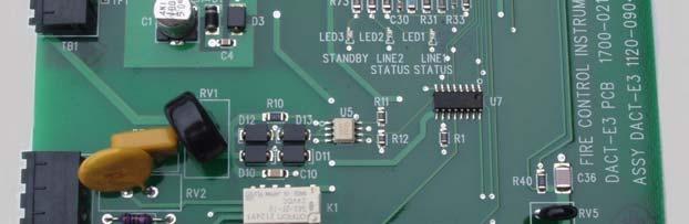
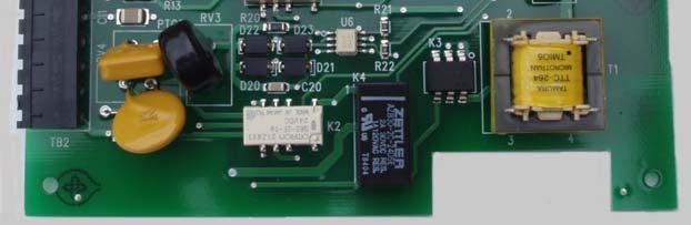
80 Figure 3-10.A DACT-E3 Figure 3-10.B DACT-E3 Sub-Assembly Page 74 of 94
81 3.4.2 DACT-E3 Event Reporting Codes The DACT-E3 event reporting codes are shown in Table 3-6 below: Table 3-6 DACT-E3 Event Reporting Codes* Event SIA Contact ID 4/2 3/1 Fire Alarm (Smoke or Manual Station) FA FA GGT GGT 0T 0 Trouble (Smoke or Manual Station) FT GG GG Trouble Restored (Smoke or Manual Station) FJ GG GG Supervisory / Tamper SS GGT GGT 6T 6 Supervisory Restored SR GGT GGT 7T 7 Supervisory/Tamper/Waterflow Trouble ST GGT GGT 8T 8 Supv/Tamper/Waterflow Trouble Restored SJ GGT GGT 7T 7 PAS QA GGT GGT 0T 0 PAS Restored QH GGT GGT 2T 2 Trouble (Non-Loop Device, AOM) FT T 8 Trouble Restored (Non-Loop Device, AOM) FJ T 7 Fire Alarm Restored QA GGT GGT 2T 2 AC Fall AT T 8 AC Fall Restored AR T 7 Phone Line 1 Fault* LT Phone Line 1 Fault Restored* LR Phone Line 2 Fault* LT Phone Line 2 Fault Restored* LR Automatic Test (NORMAL) RP Automatic Test (With Exception) RP For Contact ID and SIA Formats *Default codes as shipped from the factory. GG = group number assigned to the device, T (For networked systems, GG Node number) = Type of device or event causing event to be reported IF T =: 0= Non-loop event 1= Any event or device type not listed below 2= Manual Station 3= Supervisory Device (Non-latching) 4= Supervisory Device (Latching) 5= Waterflow (Non-silenceable) 6= Smoke Alarm 7= Non-Reporting Device 8= Multilevel Device The DACT-E3, when using Contact ID or SIA Format, sends the event type string indicating alarm/supervisory/or trouble, to the monitoring center followed by the GROUP number (GG) to which the device has been assigned (not the device address). The final digit (represented by T in the chart, provides information on the type of device which generated the event. Page 75 of 94
82 3.4.3 Telephone Requirements DC Ringer Equivalence Number (REN) = 0.5B AC Ringer Equivalence Number = 1.3 Complies with FCC Part 8 The REN is used to determine the quantity of devices that may be connected to the telephone line. Excessive RENs on the telephone line may result in the devices not ringing in response to an incoming call. In most, but not all areas, the sum of the RENs should not exceed five (5). To be certain of the number of devices that may be connected to the line, as determined by the total RENs, contact the telephone company to determine the maximum REN for the calling area. See Table 3-7 for the DACT-E3 wiring connections. Table 3-7 DACT-E3 Wiring Connections Designation Description Comments TB1-1 COM A in COM A from ILI-MB-E3 TB1-2 COM B in COM B from ILI-MB-E3 TB1-3 COM A out COM A out to other devices TB1-4 COM B out COM B out to other devices TB V in + 24 VDC from PM-9 TB4-3 or TB4-5 TB V in -24 VDC from PM-9 TB4-4 or TB4-6 TB2-1 T1 Tip Line 1 Tip In from street Non power-limited TB2-2 T1 Ring Line 1 Ring In from street Non power-limited TB2-3 P1 Tip Line 1 Tip Out to phone Non power-limited TB2-4 P1 Ring Line 1 Ring Out to phone Non power-limited TB2-5 T2 Tip Line 2 Tip In from street Non power-limited TB2-6 T2 Ring Line 2 Ring In from street Non power-limited TB2-7 P2 Tip Line 2 Tip Out to phone Non power-limited TB2-8 P2 Ring Line 2 Ring Out to phone Non power-limited Specifications Operating voltage: Operating current: Alarm current: Supervised Non Power-limited 24 VDC (from PM-9 power supply) amp amp Page 76 of 94


83 Figure 3-11.A Repeater RPT-E3 Figure 3-11.B Repeater RPT-E3 Sub-Assembly Page 77 of 94
84 3.5 Repeater Sub-Assembly (RPT-E3) (Optional) The Repeater, RPT-E3 provides the interface between the ILI-MB-E3 and the Broadband Network. It can also be used with the NGA. The RPT-E3 is available in two versions: RPT-E3-FO RPT-E3-UTP RPT-E3-FO The RPT-E3-FO communicates to the network by means of fiber-optic cable or copper, unshielded, twisted-pair wire RPT-E3-UTP The RPT-E3-UTP connects to the network by means of unshielded, twisted-pair copper wire. It is similar to the RPT-E3-FO with the exception that connectors U4, U5, U6 and U7 are omitted. Table 3-8 Repeater-E3 Wiring Connections Designation Description Comments TB1-1 ARCNET PORT 1A Broadband Network TB1-2 ARCNET PORT 1B Broadband Network TB1-3 ARCNET PORT 2A Broadband Network TB1-4 ARCNET PORT 2B Broadband Network TB2 Earth Ground TB3-1 Com A In Local Differential ARCNET TB3-2 Com B In Local Differential ARCNET TB3-3 Com A Out Local Differential ARCNET TB3-4 Com B Out Local Differential ARCNET TB V In TB4-2 Common In TB V Out TB4-4 Common Out J10 ARCNET Connector to ILI-MB-E3, NGA, or ILI-S-E3 U5* Fiber Port 2 In U7* Fiber Port 2 Out U4* Fiber Port 1 In U6* Fiber Port 1 Out J1 through J9 NOTE: If J10 is used, do not use TB3 or TB4. *U4, U5, U6 and U7 are omitted on the RPT-E3-UTP. For use during commissioning only. Not for use in the field Specifications Operating voltage: Operating current: Operating temperature: Relative humidity: Supervised Power-limited 24 VDC FWR (from PM-9 power supply) amp 32 to 120 F (0 to 49 C) 0 to 93%, non-condensing at 90 F (32 C) Page 78 of 94


85 Figure 3-12.A ILI-S-E3 Signaling Line Circuit Sub-Assembly Figure 3-12.B ILI-S-E3 Signaling Line Circuit Sub-Assembly Page 79 of 94
86 3.6 Intelligent Loop Interface Expansion Board (ILI-S-E3) (Optional) The ILI-S-E3 provides the E3 Series control panel with two (2) additional signaling line circuits. The layout is similar to the ILI-MB-E3 with the exception that a number of components are omitted ILI-S-E3 Wiring Connections See Table 3-9 for the ILI-S-E3 wiring connections. Table 3-9 ILI-S-E3 Field Wiring Connections Designation Description Comments TB1-1, TB V IN +24 VDC Input TB1-2, TB1-4 GND Common negative from PM-9 TB4-2 TB1-1 Not used TB1-2 Not used TB4-1 SLC 2 A- SLC 2 Style 6 Return TB4-2 SLC 2 A+ SLC 2 Style 6 Return TB4-3 SLC 2 B- SLC 2 Style 4 Out TB4-4 SLC 2 B+ SLC 2 Style 4 Out TB4-5 SLC 1 A- SLC 1 Style 6 Return TB4-6 SLC 1 A+ SLC 1 Style 6 Return TB4-7 SLC 1 B- SLC 1 Style 4 Out TB4-8 SLC 1 B+ SLC 1 Style 4 Out TB6-1 RS-232 GND TB6-2 RS-232 RxD TB6-3 Supervision TB6-4 RS-232 TxD W1, W2 Jumper Factory use only. W4 Jumper OUT = Normal Operation. IN = If the ILI-S-E3 is located at the end of the ARCNET bus. W7, W8 Jumper MB = For Master Box. PR = For Polarity Reversal *W9 Jumper OUT = Normal Operation. IN = If the ILI-S-E3 is supervising the PM-9 for Ground Fault. W10 Jumper OUT = Normal Operation. IN = To Disconnect SLC #1. W11 Jumper OUT = Normal Operation. IN = To Disconnect SLC #2. W13 Jumper OUT = Normal Operation. IN = To Disconnect the Audible Sounder. W14 Jumper IN = Changes baud rate to 115,200. OUT = Baud rate configured at commissioning. J2, J5 Connector Connects to J2 and J5 of the next ILI-S-E3. J4 Connector Connects to J7 of INI-VG or J10 of RPT-FO/UTP *Note 1: Must be IN if this sub-assembly is monitoring the PM-9. Jumper is OUT for other subsequent sub-assemblies. *Note 2: Must be IN for first ILI-S-E3 or INI-VG. When W9 is installed, remove JMP1 in PM Specifications Operating voltage: 24 VDC (from PM-9 power supply) Operating current: amp. Alarm current: amp. Operating temperature: 32 to 120 F (0 to 49 C) Relative humidity: 0 to 93% non-condensing at 90 F (32 C) Supervised Power-limited Page 80 of 94

 B")
 Page")
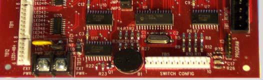
87 Figure 3-13.A Remote LED Driver Module (ANU-48) Figure 3-13.B Remote LED Driver Module (ANU-48) Page 81 of 94
88 3.7 Remote LED Driver Sub-Assembly (ANU-48) (Optional) The ANU-48 is remotable and provides output to a remote annunciator which may be located up to 3,000 feet from the panel. Up to fifteen (15), additional annunciators can be connected. See the chart below for the resistance limitations for the connecting circuit. Note that if more than four (4), ANU-48 sub-assemblies are installed, an external regulated and power-limited power supply Listed for use with fire protective signaling units is required. Quantity of the ANU-48 assemblies Maximum resistance of the 24 VDC power circuit (ohms) to the most distant ANU ANU-48 Wiring Connections See Table 3-10 for the ANU-48 wiring connections. Note: For ASM-16 or ANU-48 wiring details, see Section ASM-16 or ANU- 48 Wiring Connections (Table 3-4 and Figure 3-8). Table 3-10 ANU-48 Wiring Connections Designation Description Comments TB1-1 to 4 Remote RS-485 Output TB5-1 SW1 *SPST - maintained or momentary TB5-2 SW2 *SPST - maintained or momentary TB5-3 SW3 *SPST - maintained or momentary TB5-4 SW4 *SPST - maintained or momentary TB5-5 SW5 *SPST - maintained or momentary TB5-6 SW6 *SPST - maintained or momentary TB5-7 SW7 *SPST - maintained or momentary TB5-8 SW8 *SPST - maintained or momentary TB5-9 Common for SW1, SW2 TB5-10 Common for SW3, SW4 TB5-11 Common for SW5, SW6 TB5-12 Common for SW7, SW8 TB6-1 to -8 LEDs 1 to 8 Negative outputs to remote LEDs TB7-1 to -8 LEDs 9 to 17 Negative outputs to remote LEDs TB8-1 to -8 LEDs 18 to 26 Negative outputs to remote LEDs TB9-1 to -8 LEDs 27 to 33 Negative outputs to remote LEDs TB10-1 to -8 LEDs 34 to 42 Negative outputs to remote LEDs TB11-1 to -8 LEDs 43 to 48 Negative outputs to remote LEDs TB12-1 to -8 LED1-48+ Positive common output for remote LEDs TB13-1 EXT PWR + + From external power supply (max. 24 VDC) TB13-2 EXT PWR - - From external power supply J1 RS-485 input connection to ANU-48 J2 RS-485 connection to next ANU-48 J3 Program Factory use JMP1 Factory use JMP2 IN when using internal power JMP3 IN when using external power JMP4 Factory use JMP5 Factory use * ma. Max Page 82 of 94
89 3.7.2 ANU-48 DIP Switch Addresses The address of the ANU-48 in the system is set via the DIP Switch. See the ANU-48 Installation Instructions, P/N for addressing instructions Specifications Operating voltage: 24 VDC FWR (from PM-9 power supply) Operating current: amp* Supervised Power-limited *Add.003 amp for any LED to be lit for any condition when powered internally. When powered externally, each output driver circuit provides a maximum of.050 amp with a maximum of 2.4 amps per ANU-48 sub-assembly (48 circuits). Each load must have a minimum resistance of 544 Ohms when the external power is supplied from a PM-9. When powered internally, each LED must have a current limiting resistor in series to limit the current to.003 amps max per LED. (Example: 8.87K 1% or 9.1K 5%). 3.8 Panel Display LCD-E3 The LCD-E3 provides an 80-character display of system events together with indicating LEDs and control switches. It may be remotely located via a local RS-485 serial interface. The ILI-MB-E3 will support up to six (6), LCD-E3 displays. See Table 3-11 for the field wiring connections. Figure 3-14.A LCD-E3 Sub-Assembly Page 83 of 94
90 Figure 3-14.B LCD-E3 Sub-Assembly Table 3-11 LCD-E3 Field Wiring Connections Designation Description Comments TB V in from ILI-MB-E3 TB3-6 non-resettable B+ TB1-2 GND ILI-MB-E3 TB3-7 TB1-3 RS-485A RS-485A output from ILI-MB-E3 TB1-4 RS-485B RS-485B output from ILI-MB-E3 TB1-5 RS-485A RS-485A input from ILI-MB-E3 TB1-6 RS-485B RS-485B input from ILI-MB-E3 TB1-7 GND Connect to earth ground TB1-8 Not used J1 Local RS-485 Alternate RS-485 connection J2 Keypad To keypad J3 Display To display J4 Factory use Address Addresses 1 to 6 are set via SW Specifications Operating voltage: Operating current: Alarm current Supervised Power-limited 24 VDC FWR (from PM-9 power supply) amp amp Page 84 of 94
 (Optional) The E3 Series System can accommodate up to five (5), Remote Display subassemblies via the RS-485 serial interface.")
91 Figure 3-15 LCD-7100 Remote Display 3.9 Remote Display Sub-Assembly (LCD-7100) (Optional) The E3 Series System can accommodate up to five (5), Remote Display subassemblies via the RS-485 serial interface. The LCD-7100 Serial Remote Annunciator provides an 80-character display and function keys for Alarm Acknowledge, Trouble Acknowledge, Signal Silence, System Reset/Lamp Test and System Drill Test. The 80-character display shows all pertinent information except for menus. Keypad functions are enabled only when the keylock is turned to the Unlocked position, with the exception of the Trouble Acknowledge switch which silences the local audible trouble sounder. Operating LEDs provided are: Alarm Power Fault Supervisory System Silenced System Trouble NAC #1 Silenced and NAC #2 Silenced Address Addresses from 1 to 5 are set via the address switch SW Specifications Operating voltage: Operating current: Alarm current: Supervised Power-limited 24 VDC FWR (from PM-9 power supply) amp amp Mounting The LCD-7100 is flush or surface mounted on a standard four-gang electrical box. Page 85 of 94
E3 Series Broadband System
 Voice Evacuation E3 Series Broadband System Intelligent, Networked, Multi-Channel Fire Alarm Control and Emergency Voice Evacuation System General The, E3 Series Broadband System is a modular design and
E3 Series Broadband. Description. Features. Intelligent, Networked, Multi-Channel Fire Alarm Control and Emergency Voice Evacuation System
 Broadband Description Intelligent, Networked, Multi-Channel Fire Alarm Control and Emergency Voice Evacuation System The Broadband System includes the Net- SOLO Broadband System. Like the NetSOLO Broadband
NetSOLO Broadband. Voice Evacuation. Intelligent, Networked, Multi-Channel Fire Alarm Control and Emergency Voice Evacuation System
 Voice Evacuation NetSOLO Broadband Intelligent, Networked, Multi-Channel Fire Alarm Control and Emergency Voice Evacuation System General The NetSOLO Broadband is a revolutionary advance in fire detection
E3 Series Broadband System
 Broadband System Description The, Broadband System includes the NetSOLO Broadband System. Like the Net- SOLO Broadband System, the Broadband is of modular design and allows a wide range of configurations
FireNET FN-LCD-S Serial Annunciator Installation and Operation Manual
 FireNET FN-LCD-S Serial Annunciator Installation and Operation Manual Hochiki America Corporation 7051 Village Drive, Suite 100 Buena Park, CA 90621-2268 714.522.2246 Corporate Headquarters 800.845.6692
NetSOLO Classic. Voice Evacuation. Intelligent, Networked, Multi-Channel and Bulk Amplification Voice Evacuation System FEATURES & BENEFITS.
 Voice Evacuation NetSOLO Classic Intelligent, Networked, Multi-Channel and Bulk Amplification Voice Evacuation System General The NetSOLO Classic System is a revolutionary advance in emergency voice evacuation
FCPS-24F FIRE ALARM FIELD CHARGER/POWER SUPPLY FOR FIRE PROTECTION/SIGNALING SERVICE FCPS-24F/FCPS-24FE. Field Charger/Power Supply
 One Fire-Lite Place Northford, CT 06472 Phone: (203) 484-7161 FAX: (203) 484-7118 FCPS-24F FIRE ALARM FIELD CHARGER/POWER SUPPLY FOR FIRE PROTECTION/SIGNALING SERVICE FCPS-24F/FCPS-24FE Field Charger/Power
ECC-50DA/E ECC-125DA/E ECC-50BDA/E. Distributed Audio Amplifiers. Installation Manual C. Document LS FL-E 1/30/2014 Rev:
 Distributed Audio Amplifiers ECC-50DA/E ECC-125DA/E ECC-50BDA/E Installation Manual C P/N LS10027-000FL-E:C ECN 14-121 Document LS10027-000FL-E 1/30/2014 Rev: Fire Alarm & Emergency Communication System
Conventional Fire Alarm Control Panel
 Conventional Fire Alarm Control Panel INSTALLATION and OPERATION MANUAL NOTICE All information, documentation, and specifications contained in this manual are subject to change without prior notice by
Network Display Unit Installation Instructions
 Network Display Unit Installation Instructions Introduction This publication describes the installation procedures for the optional Network Display Units (NDUs). This product is compatible with both the
Model SK Installation and Operations Manual. Fire Control / Communicator. Document Rev: P P/N :P ECN:
 Model SK-5208 Fire Control / Communicator Installation and Operations Manual Document 151204 Rev: P P/N 151204:P ECN: 17-0298 Installation Procedure Adherence to the following will aid in problem-free
4100U City and Relay Cards Installation Instructions
 4100U City and Relay Cards Installation Instructions Introduction This publication describes the installation procedure for the following: 4100-6031/6032 City Circuit Cards 4100-6033 Alarm Relay Card Inspecting
Installation and Operation Guide. EVS-Series. Emergency Voice System. Document: LS SK-E ECN:
 Installation and Operation Guide EVS-Series Emergency Voice System Document: LS10062-001SK-E Rev: C ECN: 17-0212 Fire Alarm & Emergency Communication System Limitations While a life safety system may lower
DATA SHEET CHEETAH XI 50 INTELLIGENT SUPPRESSION CONTROL SYSTEM DESCRIPTION APPROVALS: SYSTEM OPERATION. Form No. D
 DATA SHEET CHEETAH XI 50 INTELLIGENT SUPPRESSION CONTROL SYSTEM DESCRIPTION Fike s Cheetah Xi 50 (P/N 10-071) is a state-of-the-art true intelligent digital peer-to-peer modular suppression control system.
The RPT-485W/RPT-485WF
 12 Clintonville Road Northford, CT 06472 203/484-7161 FAX: 203/484-7118 The RPT-485W/RPT-485WF EIA-485 Annunciator Loop Repeater for Twisted Pair Wiring/Fiber Optic Cable Document 15640 08/13/97 Revision:
7100 SERIES FIRE ALARM CONTROL
 7100 SERIES FIRE ALARM CONTROL INSTALLATION/OPERATING MANUAL Copyright 1998 Part Number: 9000-0447 All Rights Reserved Version 1.4 Published in U.S.A. 301 2nd Ave. Waltham, MA 02451-1133 USA TEL: (781)
MODUL-R FIRE ALARM CONTROL PANELS. MR-2900/MR-2920 Addressable Fire Alarm Control Panels MEA. Features. Description
 MODUL-R FIRE ALARM CONTROL PANELS MR-2900/MR-2920 Addressable Fire Alarm Control Panels Description MR-2900 Fire Alarm Control Panel The MR-2900 fire alarm system control unit is the heart of a sophisticated
HP101U Conventional Fire Alarm Control Panel Installation And Operation Manual
 HP101U Conventional Fire Alarm Control Panel Installation And Operation Manual NOTICE All information, documentation, and specifications contained in this manual are subject to change without prior notice
DATA SHEET CYBERCAT 254 INTELLIGENT FIRE ALARM CONTROL SYSTEM DESCRIPTION APPROVALS: SYSTEM OPERATION. Form No. D
 DATA SHEET CYBERCAT 254 INTELLIGENT FIRE ALARM CONTROL SYSTEM DESCRIPTION Fike s CyberCat 254 (P/N 10-066) is a state-of-the-art true intelligent digital peer-to-peer modular fire alarm control system.
SILENT KNIGHT. Model SK-2/E & SK-4/E. Installation and Operations Manual. Fire Alarm Control Panel. Part Number Rev. A ECN /08/05
 SILENT KNIGHT Model SK-2/E & SK-4/E Fire Alarm Control Panel Installation and Operations Manual Part Number 52604 Rev. A ECN 05-276 08/08/05 Fire Alarm System Limitations An automatic fire alarm system
HCA Series Conventional Fire Alarm System (HCA-2, HCA-2D, HCA-4, HCA-4D, HCA-8, HCA-8D) Installation and Operation Manual
 Installation and Operation Manual") HCA Series Conventional Fire Alarm System (HCA-2, HCA-2D, HCA-4, HCA-4D, HCA-8, HCA-8D) Installation and Operation Manual Hochiki America Corporation 7051 Village Drive, Suite 100 Buena Park, CA90621-2268
HCA Series Conventional Fire Alarm System (HCA-2, HCA-2D, HCA-4, HCA-4D, HCA-8, HCA-8D) Installation and Operation Manual Hochiki America Corporation 7051 Village Drive, Suite 100 Buena Park, CA90621-2268
MS-4012/4024 and CMS-4012/4024. Instruction Manual for the. Fire Alarm Control Panels
 R 12 Clintonville Road, Northford, CT 06472 Phone: (203) 484-7161 FAX: (203) 484-7118 Instruction Manual for the MS-4012/4024 and CMS-4012/4024 Fire Alarm Control Panels Document 15586 5/11/93 Revision:
Booster Power Supply Manual
 Supply Manual DEVELOPED BY COPYRIGHT NOTICE General Signal Building Systems Corporation 6411 Parkland Drive Sarasota, FL 34243 (941) 739-4300 Copyright 1999 General Signal Building Systems Corporation
EXTINGUISHING AGENT RELEASE MODULE
 EXTINGUISHING AGENT RELEASE MODULE Operation, Installation & Programming Manual Revision 3.00 Distributors For: 18-20 Brookhollow Ave telephone 02 8850 2888 www.firesense.com.au Baulkham Hills NSW 2153
FCPS-24F/FCPS-24FE. Field Charger/Power Supply D P/N 50079:D ECN Installation, Operation and Application Manual
 12 Clintonville Road Northford, CT 06472 203-484-7161 FAX: 203-484-7118 FCPS-24F/FCPS-24FE Field Charger/Power Supply Installation, Operation and Application Manual Document #50079 05/23/97 Rev: D P/N
CHEETAH XI INTELLIGENT SUPPRESSION CONTROL SYSTEM
 CHEETAH XI INTELLIGENT SUPPRESSION CONTROL SYSTEM DESCRIPTION Fike s Cheetah Xi (P/N 10-068) is a state-of-the-art true intelligent digital peer-topeer modular suppression control system. It is ideal for
HCA Series Conventional Fire Alarm System (HCA-2, HCA-2D, HCA-4, HCA-4D, HCA-8, HCA-8D) Installation and Operation Manual
 Installation and Operation Manual") HCA Series Conventional Fire Alarm System (HCA-2, HCA-2D, HCA-4, HCA-4D, HCA-8, HCA-8D) Installation and Operation Manual Hochiki America Corporation 7051 Village Drive, Suite 100 Buena Park, CA90621-2268
HCA Series Conventional Fire Alarm System (HCA-2, HCA-2D, HCA-4, HCA-4D, HCA-8, HCA-8D) Installation and Operation Manual Hochiki America Corporation 7051 Village Drive, Suite 100 Buena Park, CA90621-2268
/9308 External Battery Chargers Installation Instructions
 4081-9306/9308 External Battery Chargers Installation Instructions Introduction This publication describes the installation procedure for an External Battery Charger used with the 4100U or 4100ES System.
CMP-2401B/CMP-2402B. Fire Alarm Control Panel. Installation, Maintenance and Operating Instruction Manual
 10 Whitmore Road Woodbridge, Ontario L4L 7Z4 Phone (905) 856-8733 FAX (905) 856-9687 CMP-2401B/CMP-2402B Fire Alarm Control Panel Installation, Maintenance and Operating Instruction Manual P/N 50907:A1
The ACM-8R Annunciator Control Module
 12 Clintonville Road Northford, CT 06472 203-484-7161 FAX: 203-484-7118 The Annunciator Control Module For the System 500, System 5000, AFP-200, AM2020, AFP1010 and SFP-1024 Fire Alarm Control Panels Document
TECHNICAL DATA. Humidity: 85% Relative Humidity (non-condensing) at 90 F (32 C) maximum.
 at 90 F (32 C) maximum.") September 29, 1997 Firecycle III 433 a 1. PRODUCT NAME VIKING Model E-1 Manufactured 1997 Present 2. MANUFACTURED FOR THE VIKING CORPORATION 210 N Industrial Park Road Hastings, Michigan 49058, U.S.A.
September 29, 1997 Firecycle III 433 a 1. PRODUCT NAME VIKING Model E-1 Manufactured 1997 Present 2. MANUFACTURED FOR THE VIKING CORPORATION 210 N Industrial Park Road Hastings, Michigan 49058, U.S.A.
ACC-25/50ZST. Zoned System Voice with Telephone Evacuation Control Panel
 ACC-25/50ZST Zoned System Voice with Telephone Evacuation Control Panel General The AUDIO COMMAND CENTER 25/50 Zone System with FireFighters Telephone (ACC-25/50ZST) is a state-of-the-art Emergency Voice
MPC-6000 / MPC-7000 / RND-2
 MPC-6000 / MPC-7000 / RND-2 Fire Alarm System Control Unit Installation, Operation and Maintenance Manual Siemens Building Technologies, Inc. 8 Fernwood Road Florham Park, NJ 07932 Tel: (973) 593-2600
TECHNICAL DATA OBSOLETE
 Deluge Devices 270a 1. PRODUCT NAME VIKING PAR-3 Available since 1991 2. MANUFACTURED FOR: THE VIKING CORPORATION 210 N. Industrial Park Road Hastings, Michigan 49058 U.S.A. Telephone: (269) 945-9501 (877)
Fire Alarm Control Panels MS-2 & MS-4 MS-2E & MS-4E. Instruction Manual. Document /6/2014 Rev: G3 P/N 51512:G3 ECN
 Fire Alarm Control Panels MS-2 & MS-4 MS-2E & MS-4E Instruction Manual Document 51512 8/6/2014 Rev: G3 P/N 51512:G3 ECN 14-523 Fire Alarm & Emergency Communication System Limitations While a life safety
Version 1.0. NetSOLO Broadband Fire Alarm / Emergency Voice Evacuation System Engineer/Architect Specification Part No
 NetSOLO Broadband Fire Alarm / Emergency Voice Evacuation System Engineer/Architect Specification Part No. 9020-0581 Version 1.0 Copyright 2003 All Rights Reserved Published in the USA 16 Southwest Park,
FireSeeker Fire Alarm Control Panel Model FS-250 Installation, Operation and Maintenance Manual
 FireSeeker Fire Alarm Control Panel Model FS-250 Installation, Operation and Maintenance Manual P/N 315-049353-1 Siemens Building Technologies Fire Safety TABLE OF CONTENTS INTRODUCTION... 1 CONTROL PANEL
Cautions and Warnings. Introduction 4009 NAC POWER EXTENDER
 Cautions and Warnings DO NOT INSTALL ANY SIMPLEX PRODUCT THAT APPEARS DAMAGED. Upon unpacking your Simplex product, inspect the contents of the carton for shipping damage. If damage is apparent, immediately
Instruction Manual. CMP-12/24 Fire Alarm Control Panel. 12 Clintonville Road, Northford, CT DOCUMENT /11/96 REV: D1
 12 Clintonville Road, Northford, CT 06472 Instruction Manual CMP-12/24 Fire Alarm Control Panel DOCUMENT 15819 3/11/96 REV: D1 P/N 15819:D1 ECN 96-047 Installation Precautions - Adherence to the following
30.45 Electric Release PDRP-2001
 The PDRP-2001 Fire Alarm Control Panel (FACP) is a six-zone control panel for single and dual hazard deluge and preaction applications. The FACP is compatible with conventional input devices (2-wire or
Annunciator Modules. for Fire Lite Fire Alarm Control Panels. Document # /30/95 Revision:
 12 Clintonville Road Northford, CT 06472 203-484-7161 FAX: 203-484-7118 Annunciator Modules for Fire Lite Fire Alarm Control Panels Document # 15390 3/30/95 Revision: P/N 15390:C ECN 95-210 C Installation
PN: 51883:D ECN Field Charger/Power Supply FCPS-24FS6 FCPS-24FS8. Document # /14/05 Revision: D
 PN: 51883:D ECN 05-384 Field Charger/Power Supply FCPS-24FS6 FCPS-24FS8 Document #51883 9/14/05 Revision: D Fire Alarm System Limitations An automatic fire alarm system typically made up of smoke detectors,
ANNUNCIATOR FIXED MODULE
 12 Clintonville Road Northford, CT 06472 Phone: 203-484-7161 Fax: 203-484-7118 THE ANNUNCIATOR FIXED MODULE Installation Manual for the AFM-16ATF and AFM-32AF Annunciator Modules Document # 15970 3/27/95
The System 5000 Operating Manual
 12 Clintonville Road, Northford, CT 06472-1610 203-484-7161 FAX: 203-484-7118 The System 5000 Operating Manual C Document 15581 04/17/97 Rev: P/N 15581:C ECN 97-148 Installation Precautions - Adherence
CHABOT-LAS POSITAS COMMUNITY COLLEGE DISTRICT CHABOT COLLEGE BIOLOGICAL SCIENCES B2100 BUILDING ANNEX BID NO
 CHABOT-LAS POSITAS COMMUNITY COLLEGE DISTRICT CHABOT COLLEGE BIOLOGICAL SCIENCES B2100 BUILDING ANNEX BID NO. 18-01 ADDENDUM NO. TWO DATE: December 20, 2017 CLIENT / PROJECT: Chabot-Las Positas CCD Biological
MODEL IFP-2000/ RPS-2000
 MODEL IFP-2000/ RPS-2000 Analog/Addressable Fire System Installation and Operations Manual Part Number 151430 Rev A Installation Procedure Adherence to the following will aid in problem-free installation
MS-2410BC. Conventional Fire Alarm Control Panel. Programming, Installation, Maintenance and Operating Instruction Manual
 24 Viceroy Road Unit #6 & 7 Concord, Ontario L4K2L9 Phone (905) 660-7210 FAX: (905) 660-7204 MS-2410BC Conventional Fire Alarm Control Panel Programming, Installation, Maintenance and Operating Instruction
Fire Alarm Control Panel. Installation, Commissioning & Operating Manual
 RE 150D Fire Alarm Control Panel Installation, Commissioning & Operating Manual RAVEL ELECTRONICS PVT LTD., 150-A, Electronics Industrial Estate, Perungudi, Chennai - 600 096. Ph.: 91-44-24961004, 24960825.
Supplement to the AM2020/AFP1010 Voice Alarm Multiplex Manual Number 15889, Revision F1, dated 12/11/97
 Supplement to the AM2020/AFP1010 Voice Alarm Multiplex Manual Number 15889, Revision F1, dated 12/11/97 This supplement includes the following: Document Divider Information... page 2 Replace the following
TrueAlarm Fire Alarm Systems
 OPERATOR OPERATOR OR TROUBLE CONDITION: TO : FIRE PRIORITY 2SYSTEM SYSTEM SIGNALS POWER INDICATOR. SUPERVISORYTROUBLE SILENCED ON D. TO SILENCE SIGNALS: - PRESS " SILENCE". SUPV TBL SYSTEM ACK ACK ACK
Model 17A00 Expansion Enclosure
 HOME AUTOMATION, INC. Model 17A00 Expansion Enclosure Installation Manual Document Number 17I00-1 Rev A March, 2002 Home Automation, Inc. Model 17A00 Expansion Enclosure Installation Manual Document Number
Fire Safety. Installation Instructions Model SMB-2 Main Control Board OPERATION INSTALLATION
 Fire Safety Installation Instructions Model SMB- Main Control Board OPERATION The SIEMENS Model SMB- board in each MXL-IQ System controls operations and monitors input device identity, network communication,
Data Sheet Fire Safety & Security Products. System Overview. Initiating Circuits SXL-EX FACP 7906
 s Data Sheet Fire Safety & Security Products SXL-EX Fire Alarm Control Panel Conventional Zone Fire Alarm Control Panel ARCHITECT AND ENGINEER SPECIFICATIONS Four (4) zones expandable to eight (8) zones
PIER 4 PHASE 2 RECONFIGURATION PROJECT NO CONTRACT NO
 Question & Answer #1 PIER 4 PHASE 2 RECONFIGURATION PROJECT NO. 091251 CONTRACT NO. 070136 1. BIDDER QUESTION Are the following Electrical specs going to be added to for Port of Tacoma project? 15kV MV
DS7400Xi Addressable Control/ Communicator
 DS7400Xi Addressable Control/ Communicator DS7400Xi DS7400Xi-EXP 110VAC operation 220VAC operation Remotely Programmable WDSRP (Windows Detection Systems Remote Programming Software), allows the systems
SPECIFICATION MICROMIST FIRE SUPPRESSION SYSTEM WITH SHP-PRO CONTROL PANEL
 SECTION 1 - GENERAL CONDITIONS I. SCOPE: This specification outlines the requirements for a Fike Micromist Water Mist Fire Suppression System with automatic detection and control. The work described in
PN: 51604:A ECN Voice Evacuation Control Panel FIRE COMMAND 25/50X & FIRE COMMAND 25/50XE. Document # /17/02 Rev.
 PN: 51604:A ECN 01-507 Voice Evacuation Control Panel FIRE COMMAND 25/50X & FIRE COMMAND 25/50XE Document #51604 01/17/02 Rev. 2002 Fire Lite A Fire Alarm System Limitations An automatic fire alarm system
Control Panel. 1.0 GENERAL SCOPE OF WORK Introduction... 2
 Architectural & Engineering Specifications Control Panel 1.0 GENERAL... 2 1.1 SCOPE OF WORK... 2 1.1.1 Introduction... 2 1.2 GENERAL CONDITIONS... 2 1.2.1 After-Sales Support... 2 1.2.2 Quality assurance...
SC-6 Six Supervised Control Module
 INSTALLATION AND MAINTENANCE INSTRUCTIONS SC-6 Six Supervised Control Module SPECIFICATIONS Normal Operating Voltage: Stand-By Current: Alarm Current: Temperature Range: Humidity: Dimensions: Accessories:
Panel Remote Annunciators Installation Instructions
 Panel Remote Annunciators Installation Instructions Introduction This publication describes the installation procedures for the following PIDs: 4100-9607 Remote Annunciator w/ Flexible User Interface Domestic
Specification/ Data Sheet
 Specification/ Data Sheet TRITON RP Agent Release Control Panel FEATURES Agent Release Control Panel designed specifically for suppression release operation with: Four initiating device circuits (IDCs)
SECTION DIGITAL, ADDRESSABLE FIRE-ALARM SYSTEM
 SECTION 283111 - DIGITAL, ADDRESSABLE FIRE-ALARM SYSTEM PART 1 - GENERAL 1.1 RELATED DOCUMENTS A. Drawings and general provisions of the Contract, including General and Supplementary Conditions and Division
FMR Installation Instructions. Addressable Fire System Controller
 FMR-7033 EN Installation Instructions Addressable Fire System Controller EN 2 FMR-7033 Installation Instructions Contents Contents Contents...2 1.0 Introduction...3 2.0 Description...3 3.0 Device Mounting...3
Lamp Driver Module LDM-32F
 PN 50055:C0 ECN 01-155 Lamp Driver Module LDM-32F Instruction Manual Document 50055 03/20/2001 Rev: C Fire Alarm System Limitations An automatic fire alarm system typically made up of smoke detectors,
FireSeeker Fire Alarm Control Panel Model FS-100 Installation, Operation, and Maintenance Manual
 Fire Safety FireSeeker Fire Alarm Control Panel Model FS-100 Installation, Operation, and Maintenance Manual Siemens Building Technologies, Inc. Siemens Building Technologies, Ltd. 8 Fernwood Road 2 Kenview
MT. SAN JACINTO COMMUNITY COLLEGE DISTRICT
 MT. SAN JACINTO COMMUNITY COLLEGE DISTRICT ADDENDUM NO. 5 Bid No. 2017 104 Upgrade Fire alarm System San Jacinto Campus September 15, 2016 Owner: Mt. San Jacinto Community College District 1499 N. State
PN:51264:A2 ECN Remote Fire Annunciator FDU-80. Document /14/00 Rev: A.
 PN:51264:A2 ECN 00-245 Remote Fire Annunciator FDU-80 Document 51264 6/14/00 Rev: A Fire Alarm System Limitations An automatic fire alarm system typically made up of smoke detectors, heat detectors, manual
Annunciator Control System ACS Series
 Annunciator Control System ACS Series Installation Manual Document 15842 2/15/2011 Rev: N1 P/N 15842:N1 ECN 13-771 Fire Alarm System Limitations While a fire alarm system may lower insurance rates, it
Gamewell-FCI January 11, 2016 Honeywell Fire Systems 12 Clintonville Road Northford, Connecticut Product Guide Specification
 Gamewell-FCI January 11, 2016 Honeywell Fire Systems 12 Clintonville Road Northford, Connecticut 06472-1653 Phone (203) 484-7161 Fax (203) 484-7118 Website www.gamewell-fci.com Product Guide Specification
RE 2554 RE Automatic Fire Alarm Control Panel (Protective premises Unit) Installation, Commissioning & Operating User Manual
 Installation, Commissioning & Operating User Manual") RE 2554 RE 2558 Automatic Fire Alarm Control Panel (Protective premises Unit) Installation, Commissioning & Operating User Manual Fire Alarm System Limitations An automatic fire alarm system typically
RE 2554 RE 2558 Automatic Fire Alarm Control Panel (Protective premises Unit) Installation, Commissioning & Operating User Manual Fire Alarm System Limitations An automatic fire alarm system typically
Smoke Detector Activation of any smoke detector shall start the alarm verification mode.
 Description: The purpose of the section is to provide the UMCP Design Standards for the design and implementation of Fire Alarm Systems at the UMCP campus. Related Sections: TBD Effective Date: July 10,
SPECIFICATION: AlarmLine TM INTELLIGENT LINEAR HEAT DETECTION
 1. GENERAL SPECIFICATION 1.1 The contractor shall provide an Intelligent AlarmLine Linear Heat Detection System to perform the following functionality: A. Fire Alarm, Supervisory and Trouble-Event Initiation
Series SPB Audio Boosters Installation, Testing, Operation, and Maintenance Manual
 Series SPB Audio Boosters Installation, Testing, Operation, and Maintenance Manual Part Number P84748 Assembly Number A84749 Revision C Revision A Copyright 2006 Printed in U.S.A. All rights reserved.
OJD ITB No Attachment E Duress Alarm Equipment Specifications
 Duress Alarm Equipment Specifications PART 1 GENERAL 1.1 SECTION INCLUDES A. Duress devices. B. Alarm control panel. C. Signaling devices. 1.2 REFERENCE STANDARDS A. NFPA 70 - National Electrical Code;
CFP-2410B. Programming, Installation, Maintenance and Operating Manual. Conventional Fire Alarm Control Panel.
 Conventional Fire Alarm Control Panel CFP-2410B Programming, Installation, Maintenance and Operating Manual Document 50974 2/18/04 Rev: B P/N 50974:B ECN 02-253 Fire Alarm System Limitations While a fire
INTELLIKNIGHT MODEL 5808
 INTELLIKNIGHT MODEL 5808 Addressable Fire Control Panel Installation and Operations Manual Part Number 151274 Rev J Installation Procedure Adherence to the following will aid in problem-free installation
TABLE OF CONTENTS GENERAL... 2 A. DEFINITIONS DIGITAL, ADDRESSABLE FIRE ALARM SYSTEM... 2
 Division 28 ELECTRONIC SAFETY AND SECURITY TABLE OF CONTENTS 28 0000 GENERAL... 2 A. DEFINITIONS...2 28 3111 DIGITAL, ADDRESSABLE FIRE ALARM SYSTEM... 2 A. DESIGN REQUIREMENTS...2 B. CONSTRUCTION REQUIREMENTS...2
HPFF8(E)/HPFF8CM(E) NOTIFICATION APPLIANCE CIRCUIT EXPANDER INSTALLATION & OPERATION MANUAL
/HPFF8CM(E) NOTIFICATION APPLIANCE CIRCUIT EXPANDER INSTALLATION & OPERATION MANUAL") HPFF8(E)/HPFF8CM(E) NOTIFICATION APPLIANCE CIRCUIT EXPANDER INSTALLATION & OPERATION MANUAL P/N 53499:B3 ECN 16-562 10/5/2016 Fire Alarm & Emergency Communication System Limitations While a life safety
HPFF8(E)/HPFF8CM(E) NOTIFICATION APPLIANCE CIRCUIT EXPANDER INSTALLATION & OPERATION MANUAL P/N 53499:B3 ECN 16-562 10/5/2016 Fire Alarm & Emergency Communication System Limitations While a life safety
ACSI MODEL 1410 POWER SUPPLY INSTALLATION INSTRUCTIONS
 II 1400-3 ACSI MODEL 1410 POWER SUPPLY INSTALLATION INSTRUCTIONS Features: For use with doors or groups of doors that must interlock with each other to regulate control of accessing one area from another,
SECTION FIRE ALARM SYSTEMS
 SECTION 28 3100 FIRE ALARM SYSTEMS PART 1 GENERAL 1.01 SECTION INCLUDES A. Expandable emergency evacuation fire alarm system. 1.02 RELATED SECTIONS A. Division 21 Section "Wet-Pipe Sprinkler Systems"..
CHG-120 Battery Charger Instruction Manual. Document /06/2002 Rev: B1 PN 50641: B1 ECN
 CHG-120 Battery Charger Instruction Manual Document 50641 11/06/2002 Rev: B1 PN 50641: B1 ECN 01-546 Fire Alarm System Limitations While a fire alarm system may lower insurance rates, it is not a substitute
Wiring Instructions for the 2900 Series FIREGUARD Combination Door Closer-Holder and Releasing Device with Integral Smoke Detector
 Wiring Instructions for the 900 Series FIREGUARD Combination Door Closer-Holder and Releasing Device with Integral Smoke Detector CAUTION: FAILURE TO INSTALL OR ADJUST PROPERLY MAY RESULT IN INJURY OR
LifeAlarm Fire Alarm Control Panels
 LifeAlarm Fire Alarm Control Panels UL, ULC Approved* Features Control panel operator convenience features: Wide viewing angle 2 x 20 (40 character) alphanumeric LCD and dedicated LEDs provide convenient
Single Doors FIREGUARD Series Use one Master Unit each door or one 2409 Support unit each door. Pairs of Doors
 Hinge Edge of Door Hinge Edge of Door Wiring Instructions for the Sargent 0 Series FIREGUARD Combination Door Closer-Holder and Releasing Device with Integral Smoke Detector CAUTION: FAILURE TO INSTALL
INTELLIGENT FIRE ALARM CONTROL PANEL
 INTELLIGENT FIRE ALARM CONTROL PANEL FX-2000 SERIES Description Mircom s FX-2000 Series Intelligent Analog Fire Alarm Control Panel is designed to provide maximum flexibility of analog system requirements
INTELLIKNIGHT MODEL 5700
 INTELLIKNIGHT MODEL 5700 Addressable Fire Control Panel Installation and Operations Manual Part Number 151295 Rev K ECN 09-570 08/27/09 Installation Procedure Adherence to the following will aid in problem-free
Intelligent Single Loop Fire Alarm Control Panel
 Intelligent Single Loop Fire Alarm Control Panel The CAX-CTL-1L Intelligent Single Loop Fire Alarm Control Panel is a member of the industry leading Axis AX Series Intelligent Fre Alarm Control Panels
Intelligent 2 & 4 Loop Fire Alarm Control Panels
 Intelligent 2 & 4 Loop Fire Alarm Control Panels Advanced has combined the latest technology with many years of fire experience, to create the Axis AX Series Intelligent Fire Alarm Control Panels. The
Addressable NAC Output Module D327A
 Installation Instructions Notice Addressable NAC Output Module D327A These instructions cover the installation of the D327A Addressable NAC Output Module in an analog system controlled by a Bosch D8024,
Model PAD-3 Distributed Power Module NAC Expander Installation, Operation, and Maintenance Manual
 Fire Safety Model PAD-3 Distributed Power Module NAC Expander Installation, Operation, and Maintenance Manual Siemens Building Technologies, Inc. Siemens Building Technologies, Ltd. 8 Fernwood Road 2 Kenview
FIREFLY II PLUS RELEASE DEVICES INSTALLATION MANUAL
 FIREFLY II PLUS RELEASE DEVICES INSTALLATION MANUAL MADE IN THE U.S.A. U.L. LISTED CANADIAN LISTED CSFM: 7300-1418:100 GENERAL DESCRIPTION SERIAL NUMBER The Cookson Company FIREFLY II PLUS Time Delay Release
July 14, 1999 DF C-100.
 www.firelite.com GENERAL The Fire Lite FIRE COMMAND 25/50 is a state-of-theart, compact, stand-alone or slave Emergency Voice Evacuation Control Panel (VECP). The FIRE COMMAND 25/50 is offered in a self-contained,
MMF Six Zone Interface Module
 Installation and Maintenance Instructions I56-900-005 MMF-0-6 Six Zone Interface Module SPECIFICATIONS Normal Operating Voltage: 5- VDC Stand-By Current: ma Alarm Current: 40 ma (assumes all six LEDs solid
Public Safety DAS Annunciator Panel
 Public Safety DAS Annunciator Panel 120 VAC Models: 1221-A, 1221-B, 1221-C Revision D 91117 48 VDC Models: 1221-A-48, 1221-B-48, 1221-C-48 24 VDC Models: 1221A-24, 1221-B-24, 1221-C-24 CAUTION: (Read This
Field Charger/Power Supply FCPS-24S6 FCPS-24S8. Document # /06/03 Revision: C1 PN: 51977:C1 ECN
 Field Charger/Power Supply FCPS-S6 FCPS-S8 Document #977 8/06/0 Revision: C PN: 977:C ECN 0-96 Fire Alarm System Limitations While a fire alarm system may lower insurance rates, it is not a substitute
INTELLIKNIGHT 5820XL. Installation and Operations Manual. Addressable Fire System. Document L8 04/01/2011 Rev: S P/N L8:S ECN
 INTELLIKNIGHT 5820XL Addressable Fire System Installation and Operations Manual Document 151209-L8 04/01/2011 Rev: S P/N 151209-L8:S ECN 11-0196 Installation Procedure Installation Precautions - Adherence
SECTION FIRE ALARM SYSTEMS
 SECTION 28 3100 PART 1 -GENERAL 1.01 RELATED DOCUMENTS Drawings and general provisions of the Contract, including General and Supplementary Conditions and Division 1 Specification Sections, apply to this
INTELLIKNIGHT 5820XL. Installation and Operations Manual. Addressable Fire System. Document L8 05/09/2012 Rev: T P/N L8:T ECN
 INTELLIKNIGHT 5820XL Addressable Fire System Installation and Operations Manual Document 151209-L8 05/09/2012 Rev: T P/N 151209-L8:T ECN 12-0210 Installation Procedure Installation Precautions - Adherence
LDM Series Lamp Driver Modules For Graphic Annunciation and Control
 12 Clintonville Road Northford, CT 06472 (203) 484-7161 FAX: (203) 484-7118 LDM Series Lamp Driver Modules For Graphic Annunciation and Control Used with the System 500, System 5000, AM2020/AFP1010 and
June 10, 2002 DF C S2424
 GENERAL www.firelite.com The Fire Lite FIRE COMMAND 25/50X is a state-of-theart Emergency Voice Evacuation Control Panel (VECP), with significant technological enhancements that set it apart from other