STATIONARY FILTRATION UNIT
|
|
|
- Ursula Todd
- 5 years ago
- Views:
Transcription

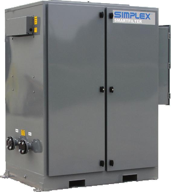
1 SMARTFILTER STATIONARY FILTRATION UNIT
2 Last Revision Date: March 10, 2016 For the most up-to-date information for this product and others, please contact Simplex, Inc. at (800) or visit us on the web at
3 Table of Contents 1 Warnings and Cautions... 1 Safety information symbols 1 Cautions 1 2 Nameplates and Placards Description and Specification... 4 Overview of use 4 Capabilities 4 4 Unpacking... 6 Included components and parts 6 Primary inspection 6 5 Installation... 7 Installing wiring 7 Installing control power 7 Installing ball valves 7 Connecting differential pressure switch 9 Installing BMS monitoring 9 Installing Dry Contact Alarms 9 6 Operating Instructions...10 Setting date and time 10 Scheduling automatic filtration cycles 10 Automatic operation 10 Manual operation 11 Transferring fuel 11 Viewing fuel quality history 12 Viewing tank status 12 Viewing filter quality summary 12 Automatic water drain 13 Water sensor operation 13 Priming the system with water 14 Filter replacement schedule 14 7 Alarms and Warnings...15 Appendix A Product Warranty...16
4 Table of Figures Dimensions...5 Conduit Entry Area...7 Ball Valve...8 Manual Override Switch...8 Valve Connectors...8
5 1 WARNINGS AND CAUTIONS Safety information symbols The following images indicate important safety information: This General warning symbol points out important information that, if not followed, could endanger personal safety and/or property. This Explosion warning symbol points out potential explosion hazards. This Fire warning symbol points out potential fire hazards. This Electrical warning symbol points out potential electrical shock hazards. Cautions Improper operation of this equipment such as neglecting its maintenance or being careless can cause possible injury or death. Permit only responsible and capable persons to install, operate, and/or maintain this equipment. Potentially lethal voltages and amperages are present in these machines. Ensure all steps are taken to render the machine safe before attempting to work on the equipment. All hardware covered by this manual have dangerous electrical voltages and can cause fatal electrical shock. Avoid contact with bare wires, terminals, connections, etc., on the hardware, if applicable. Ensure all appropriate covers, guards, grounds, and barriers are in place before operating the equipment. If work must be done around an operating unit, stand on an insulated dry surface to reduce shock hazard. Do not handle any kind of electrical device while standing in water, while barefoot, or while hands or feet are wet. DAN- GEROUS ELECTRICAL SHOCK MAY RESULT. If trained personnel must stand on metal or concrete while installing, servicing, adjusting, or repairing this equipment, place insulative mats over a dry wooden platform. Work on the equipment only while standing on such insulative mats. The National Electrical Code (NEC), Article 250 requires the frame of the equipment to be connected to an approved earth ground and/or grounding rods. This grounding will help prevent dangerous electrical shock that might be caused by a ground fault condition or by static electricity. Never disconnect the ground wire. Wire gauge sizes of electrical wiring, cables, and cord sets must be adequate to handle the maximum electrical current Warnings and Cautions 1
6 (ampacity) to which they will be subjected. Before installing or servicing this (and related) equipment, make sure that all power voltage supplies are completely turned off at their source. Failure to do so will result in hazardous and possibly fatal electrical shock. In case of accident caused by electric shock, immediately shut down the source of electrical power. If this is not possible, attempt to free the victim from the live conductor. AVOID DIRECT CONTACT WITH THE VICTIM. Use a nonconducting implement, such as a dry rope or board, to free the victim from the live conductor. If the victim is unconscious, apply first aid and seek immediate medical attention. Never wear jewelry when working on this equipment. Jewelry can conduct electricity resulting in electric shock or may get caught in moving components causing injury. Keep a fire extinguisher near the hardware at all times. Do NOT use any carbon tetra-chloride type extinguisher. Its fumes are toxic, and the liquid can deteriorate wiring insulation. Keep the extinguisher properly charged and be familiar with its use. If there are any questions pertaining to fire extinguishers, please consult the local fire department. The illustrations in this manual are examples only and may differ from your unit. Main Disconnect to be provided by installer, rated 600V maximum, sized 150% maximum of rated current. The system shall be for use with fuel oil as described by NFPA321, Basic Classification of Flammable and Combustible Liquids. As defined by this standard, the fuel supply system shall be for use with combustible liquids, those having a flash point at or above 100 F and further defined as Class II or Class III liquids. In no case shall a liquid having a flash point less than 100 F be used. In every case, the system shall not be used or applied at a temperature in excess of the flash point of the contents. Electrical equipment used in the system shall be in accordance with NFPA30, section 5-7, wherein it states For areas where Class II or Class III liquids only are stored or handled at a temperature below their flash points, the electrical equipment may be installed in accordance with provisions of NFPA70, National Electrical Code, for ordinary locations... It is the site s responsibility to accommodate for thermal expansion. Failure to install relief valves will void your warranty, as well as risk a fuel oil spill. 2 Warnings and Cautions

7 2 NAMEPLATES AND PLACARDS Nameplates and Placards 3
8 4 Nameplates and Placards
9 3 DESCRIPTION AND SPECIFICATION Overview of use Capabilities The SmartFilter is a fuel oil filtration, conditioning, and maintenance system for tanks dedicated to diesel or turbine engine generator sets or with oil-fired boiler or process heat systems. SmartFilters are intended for use with fuel oil held in bulk, long-term storage, including underground and aboveground main supply tanks, large generator sub-base tanks and large day tanks. Typical tank capacities are in excess of 5,000 gallons, with 10,000-20,000 gallon or larger tanks being common. The SmartFilter draws fuel from the bottom of the tank (25%- 33% of tank capacity) and returns the fuel with minimal disturbance of the settled strata, resulting in good filtration performance and removal of contaminants and water. Most fuel contaminants will settle from still fuel, resulting in a stratification of fuel with contaminants concentrated in the lower strata. Therefore, it is necessary to circulate and filter the lower 25-33% of the tank contents. The SmartFilter draws fuel from the bottom of the tank and returns the fuel with minimal disturbance of the settled strata, resulting in good filtration performance and removal of contaminants and water. It is recommended to size the SmartFilter to circulate and filter 25-33% of the tank capacity in a nominal 8-hour run period, once each week. Below is an example for a 20,000 gallon tank: 25% of 20,000g = 5000g to circulate and filter in an 8-hour period. 5000g/8 hours = 625 GPH or 10.4 GPM Use the Simplex SFG-10 SmartFilter For the same tank filtering 33%, or 6,600 gallons, run the SFG-10 for 11 hours or specify the SFG-20 and run for 5 hours There is no absolute rule. If it is desired to filter greater than 33%, or even 100% of the tank, simply specify a larger SmartFilter or run the filtration system longer. These are continuous duty devices. The only limit to run time is filter condition, which is constantly monitored by the SmartFilter controller. Description and Specification 5
10 PUMP INLET PUMP OUTLET SMARTFILTER ± ±1.000 Ø0.438 (18) TYP Figure 1 Dimensions 6 Description and Specification
11 4 UNPACKING Included components and parts The following items are included with your SmartFilter. If any of the following are not included, please contact your Simplex representative or call Simplex Direct, Inc., at SmartFilter 2. Manual 3. Electrical drawings package Primary inspection If any problems are observed during Primary Inspection, call Simplex 24 hours a day at Preventative visual inspection of the shipping crate and the SmartFilter is advised. Never apply power to a SmartFilter before performing this procedure. The following four-point inspection is recommended before installation and as part of a 6-month maintenance schedule: 1. If the crate shows any signs of damage, examine the SmartFilter in the corresponding areas for signs of initial problems. 2. Check the entire outside of the cabinet for any visual damage, which could cause internal electrical or mechanical problems due to reduced clearance. 3. Check electrical connections for tightness. 4. Examine all accessible internal electrical components. Unpacking 7
12 PUMP OUTLET 5 INSTALLATION Installing wiring Installing control power Installing ball valves The SmartFilter should be installed on a concrete pad at the desired location, then wired to the power source and any other sensors or system integration connections. Figure 2 Conduit Entry Area The SmartFilter must be completely wired prior to applying power. Failure to follow the wiring information and guide may result in product damage and loss of warranty coverage. If requested, startup services can be provided by Simplex Onsite, Inc. or Simplex, Inc. to check field wiring before applying power as well as assuring proper operation. Conduit Entry Area To bring cabling into the SmartFilter, pull a hole into the cabinet in the Conduit Entry Area (see Figure 2) and install a 3R-rated conduit connector for access. To install control power, connect a primary 120VAC, 60Hz, 30-amp power source to the SmartFilter s TB-PS-1-2. Ensure power source and SmartFilter are properly grounded. Ensure that the Manual Override Switches on each ball valve are set to (A) Auto. (See Manual Override Switch on page 9.) Connect the two cables provided with Motorized Ball Valve 1 to the SmartFilter controller as follows (see Ball Valve on page 9 for wire assignments:) 1. Neutral to TB-MBV-1 2. Open Valve to TB-MBV Close Valve to TB-MBV Actuator Ground to TB-MBV-4 5. Ground to TB-MBV-5 6. Valve Opened to TB-MBV Valve Closed to TB-MBV Status Common to TB-MBV-14 8 Installation

 2. Close Valve (Blue) 3. Open Valve (Black) 4. Ground (Green/Yellow) Position Signal 1. Signal Common (Brown) 2. Valve Closed (Blue) 3. Valve Opened (Black) 4.")
13 2 Motorized Ball Valve 1. Neutral to TB- MBV-2 2. Open Valve to TB- MBV Close Valve to TB- MBV Actuator Ground to TB-MBV-6 5. Ground to TB- MBV-7 6. Valve Opened to TB-MBV Valve Closed to TB- MBV Status Common to TB-MBV-19 Figure 4 Manual Override Switch Figure 5 Valve Connectors 3 Motorized Ball Valve 1. Neutral to TB- MBV-3 2. Open Valve to TB- MBV Close Valve to TB- MBV Actuator Ground to TB-MBV-8 5. Ground to TB-MBV-9 6. Valve Opened to TB-MBV Valve Closed to TB-MBV Status Common to TB-MBV-24 Figure 3 Ball Valve Actuator 1. Actuator Common (Brown) 2. Close Valve (Blue) 3. Open Valve (Black) 4. Ground (Green/Yellow) Position Signal 1. Signal Common (Brown) 2. Valve Closed (Blue) 3. Valve Opened (Black) 4. Ground (Green/Yellow) Installation 9
14 Connecting differential pressure switch Installing BMS monitoring Installing Dry Contact Alarms To connect the differential pressure switch to the SmartFilter, connect the normally open switch as follows: TB-B-15 and TB- B-4. To connect the SmartFilter to your BMS/BAS setup, connect: 1. Wire Shielding to TB-C-1 2. RS485+ to TB-C-2 3. RS485- to TB-C-3 To connect the controller to external alarms, connect TB-R to your system as follows: For Summary alarm annunciation: 1. Common to TB-R-1 2. Normally Closed to TB-R-2 3. Normally Open to TB-R-3 For Not in Auto alarm annunciation : 1. Common to TB-R-4 2. Normally Closed to TB-R-5 3. Normally Open to TB-R-6 For High Water alarm annunciation: 1. Sensor common to TB-R-7 2. Normally Closed to TB-R-8 3. Normally Open to TB-R-9 For Fuel Line Leak alarm annunciation: 1. Sensor common to TB-R Normally Closed to TB-R Normally Open to TB-R-12 For Loss of Flow alarm annunciation: 1. Common to TB-R Normally Closed to TB-R Normally Open to TB-R Installation
. 3. Select the current time, date, and day of the week and press the ACCEPT pushbutton.")


15 6 OPERATING INSTRUCTIONS Setting date and time 1. On the System Status Screen (Figure 6), press the MAIN MENU button on the touchscreen. 2. Press the SET TIME AND DATE button (see Figure 7). 3. Select the current time, date, and day of the week and press the ACCEPT pushbutton. If the AC- CEPT pushbutton is not pressed, the data will not be updated (Figure 8). Figure 6 System Status Screen Scheduling automatic filtration cycles 1. At the main menu, press the PRO- GRAM FILTER CY- CLE button. 2. Up to ten automatic filtration programs may be set by the user. Each program is set with a row of elements on this page (see Figure 9 on page 12). 3. Select the day of the week for your automatic program by pressing one of the elements in the DAY column. Press repeatedly to select the desired day of the week. Figure 7 Main Menu Figure 8 Time and Date Screen 4. Select the start time by pressing the hour and minute portions of the element in the START TIME column and entering the times on the popup keypad. 5. Select the duration of the automatic filter cycle by pressing Operating Instructions 11


16 the hour and minute portions of the element in the DURA- TION column and entering the times on the popup keypad. 6. Select the tank number from which the fuel will be drawn by pressing the element in the TANK column and entering the number on the Figure 9 Program Filter Cycle Screen popup keypad. The maximum number allowed in this element is factory set to the number of tanks designed into your control system. 7. Press the ACCEPT pushbutton. If the ACCEPT pushbutton is not pressed, the data will not be updated. When operating the SmartFilter, putting the physical Hand- Off-Auto switch on the control panel in Auto will set the filtration unit for Automatic Operation. Setting the switch in Hand mode enables Manual Operation and Fuel Transfer. Automatic operation 1. Place the Hand-Off-Auto switch in the auto position. 2. The conditioning system will now filter the fuel as programmed by the user on the PROGRAM FILTER CYCLE screen. 3. If run times overlap, and the overlapping programs are set for the same tank, the system will run the filter until the latest end time. Overlapping user programmed filter cycles is not recommended. Manual operation 12 Operating Instructions 1. Put the Hand-Off- Auto switch in Hand mode (Figure 10). 2. Press the MANU- AL pushbutton. 3. The touchscreen will change to the Manual Filtration Screen (Figure 11). 4. Enter the number of Figure 10 Manual Mode Screen

17 gallons to filter, or leave the field at 0 for unlimited filtration. 5. The pump will start and continue to run until the desired amount of fuel has been filtered, the STOP pushbutton is pressed, or a failure occurs. Most system alarm conditions are ignored when in manual. Figure 11 Manual Filtration Screen Transferring fuel Fuel transfer from one tank to another is only available on multi-tank filtration systems. 1. Put the Hand-Off-Auto switch in Hand mode 2. Press the TRANSFER button. 3. Select the amount of fuel to transfer and the source and destination tanks. 4. Press the START MANUAL FUEL TRANSFER pushbutton. 5. The pump will start and continue to run until the desired amount of fuel has been transferred, the STOP pushbutton is pressed, or a failure occurs. Most system alarm conditions are ignored when in manual. Operating Instructions 13

18 Viewing tank status At the main menu, press the TANK OVER- VIEW button on the touchscreen to enter the TANK OVERVIEW screen (Figure 12). At this screen the user can monitor the tank and valve status, as well as important information about the time since the last filtration and reset. Figure 12 Tank Overview Screen Automatic water drain The automatic water drain and water tank (if purchased) operate based on three water sensors which distinguish between water and diesel fuel. 1. The safety water sensor (the lower sensor) must sense water for the water drain system to operate. If fuel is detected in the water line, an alarm is activated to alert the operator. To restore normal operation, the operator must manually drain the water line and prime it with water so that the safety water sensor detects water. Prime the water line by pouring water in the top of the dirty fuel side of the filter canister. This alarm usually indicates a fault with the solenoid valve (stuck open) or one of the three water sensors. 2. When the filter system is in normal operation and both the upper and middle water sensors detect water in the coalescer, the water drain solenoid valve opens. 3. The water drain solenoid closes when the lower water sensor in the coalescer stops detecting water, or when one of the following conditions occurs: a. The safety water sensor detects diesel (or air). b. An Emergency Stop is activated. c. Either of the water holding tank high level floats is triggered. d. The pump stops. Water sensor operation 14 Operating Instructions The water sensors provide a signal to the PLC when they detect water. For this reason, air and diesel both look the same to the water sensors. The safety water sensor must be flooded with water for the filter to operate; air or diesel in the water drain line will trigger a Fuel in Water Line alarm. The power to the water sensors is pulsed to prolong the life
19 of the sensors: When the pump is running, the water sensors are powered for ten seconds out of every minute. The sensors are continuously powered during and for two minutes after a water drain cycle. Priming the system with water Filter replacement schedule For systems with automatic water drain, any time the water line is drained (changing the filter, etc.), it is necessary to prime the system with water. To prime the system, pour water into the top of the coalescer until it shows in the sight glass. Replace filters annually or when indicated by Smart Filter SERVICE PREFILTER or SERVICE COALESCER alarms, whichever occurs first. Simplex filter element reorder part numbers are displayed on the placard inside the door of the filter unit. Operating Instructions 15


20 7 ALARMS AND WARNINGS The SmartFilter can register a number of alarms. When an alarm is sounded, you can silence the horn on the SmartFilter by pressing the Horn Silence button. Address the issue and press the Alarm Reset button to clear the error. Do not ignore alarms and warnings, no matter how trivial they may seem. Doing so risks damage to your equipment and reduces reliability of your emergency power system. Figure 13 Alarm Banner Figure 14 Alarm Help Screen To view information about the alarm, press the notification banner that appears at the bottom of the screen (Figure 13). This will open a help screen to explain the failure (Figure 14). 16 Alarms and Warnings
21 Appendix A PRODUCT WARRANTY SIMPLEX, Inc., warrants the industrial electrical control, test and accessory equipment and parts and accessories thereof to be the kind and quality described in SIMPLEX s specifications and to be free from defects in material or workmanship under normal service, its obligations under this warranty being limited to repairing or replacing, at its option, any part or parts which shall, within twelve (12) months from date of shipment from its factory, as indicated by serial date code on the nameplate or sales records, be returned to SIMPLEX or an authorized SIMPLEX repair station, with transportation costs prepaid, and which its examination shall disclose to its satisfaction to have been thus defective. The provisions of this warranty shall not apply to any equipment, part or accessory which (a) has been improperly specified by buyer; (b) has been improperly stored or handled prior to placing in service; (c) has been improperly mounted or connected; (d) has not been operated within specifications stated on its nameplate, label or placard; (e) has not been properly maintained; (f) parts supplied by buyer for inclusion in finished equipment are not covered by this warranty; (g) components or assemblies specified by buyer with no substitution permissible that are not normally used by SIMPLEX. SIMPLEX reserves the right to reject warranty claims of any kind against assembled equipment, parts or material for which SIMPLEX has not received payment in full. Should buyer, at his own risk, elect to replace defective equipment or parts in the field rather than return equipment to SIMPLEX s factory or authorized repair station, SIM- PLEX will supply and invoice parts at normal prices upon receipt of buyer s bona-fide purchase order. Defective equipment or parts returned for in-warranty crediting in exchange for replacement parts must be returned within 45 days from date of shipment of replacement in order to qualify for warranty consideration. Defective equipment or parts returned after 45 days may be subject to a restocking charge of 20% or a minimum charge of $50.00, whichever is greater. This warranty is in lieu of all other warranties, express or implied, and all other obligations or liabilities on the part of SIMPLEX, and SIMPLEX neither assumes nor authorizes any other person to assume for it any other liability in connection with any such electrical control, test or accessory equipment or accessories or parts. Product Warranty - 17
22 WE WELCOME YOUR FEEDBACK! Simplex designs and manufactures Load Banks and Fuel Supply systems for power generation and liquid automation. Simplex is certified to ISO 9001:2008. Used world-wide for mission critical environments in manufacturing, technology, transportation, hospitals, schools, public utilities and the U.S. military, Simplex products provide solutions meeting exact requirements, from the simplest testing and proving equipment for backup generators to custom-designed and engineered mission-critical fuel systems. At Simplex, we are experts at building products that meet our customers exact requirements. For a complete listing of Simplex products visit Simplex welcomes your questions, comments, suggestions, compliments, and complaints as a way to continuously improve our service to you. Please call us at (24 hours a day) or visit


23 LOAD BANK RENTAL AND SERVICE CENTERS Simplex Onsite can place Load Banks, Cables, Transformers, and Fuel Polishers rentals as well as service technicians at your fingertips anywhere in the United States quickly and cost effectively. For information call or visit COLORADO Serving Colorado, Idaho, Montana, Nevada, Utah and Wyoming GEORGIA Serving Alabama, Florida, Georgia, North Carolina and South Carolina ILLINOIS Serving Illinois, Indiana, Kentucky, Michigan, Missouri and Tennessee MASSACHUSETTS Serving Connecticut, Delaware, Maine, Maryland, Massachusetts, New Hampshire, New Jersey, New York, Pennsylvania and Vermont MINNESOTA Serving Iowa, Minnesota, North Dakota, South Dakota and Wisconsin OHIO Serving Indiana, Michigan, Ohio, Pennsylvania (western) and West Virginia TEXAS Serving Arkansas, Louisiana, New Mexico, Oklahoma and Texas
24 5300 Rising Moon Road Springfield, IL Simplex, Inc Boggs Road Duluth, GA (800)
LC2011 FUEL LEVEL CONTROLLER 1 TANK
 LC2011 FUEL LEVEL CONTROLLER 1 TANK Last Revision Date: March 9, 2016 For the most up-to-date information for this product and others, please contact Simplex, Inc. at (800) 637-8603 or visit us on the
Watt-Muncher Load Bank Manual WATT-MUNCHER. Portable Load Bank. 6 June 2018 Simplex Service Page 1 of 13
 WATT-MUNCHER Portable Load Bank 6 June 2018 Simplex Service 800-637-8603 Page 1 of 13 This manual was last revised: 6 June 2018 For up-to-date information on this product or others, please contact Simplex
LC2011 FUEL LEVEL CONTROLLER 1 TANK
 LC2011 FUEL LEVEL CONTROLLER 1 TANK Last Revision Date: October 7, 2014 For the most up-to-date information for this product and others, please contact Simplex, Inc. at (800) 637-8603 or visit us on the
HIGH EFFICIENCY GAS-FIRED, UNIT HEATER LIST PRICES
 PRICE SHEET: NXPS-3 EFFECTIVE: July 1, 2018 SUPERSEDES: NXPS-2 HIGH EFFICIENCY GAS-FIRED, UNIT HEATER LIST PRICES ITEM PAGE HU Series Unit Number Description...2 HU Series...3 Options...4 Options - Accessories,
Soybean Form B. Counts & Measurements
 Soybean Form B Counts & Measurements Components of Forecast Row Space Measurements Number of Plants Number of pods/plant Weight of Beans/Pod How is it used? This information + Form A information is used
6. Results for the Wholesale and Retail Trade Sectors
 6. Results for the Wholesale and Retail Trade Sectors A total of seven sectors comprise the U.S. horticultural wholesale and retail trade industries: 1) wholesale flower, nursery stock & florist supply;
Continuing Education Units (CEU)
") CEUGuide Continuing Education Units (CEU) You are responsible for meeting any CEU requirements which may apply to your professional work in the low voltage industry. It is your responsibility to identify
CEUGuide Continuing Education Units (CEU) You are responsible for meeting any CEU requirements which may apply to your professional work in the low voltage industry. It is your responsibility to identify
AVERAGE RADON CONCENTRATION:
 February 2, 2017 Test Number: 1703-142 Property Inspected: 804 425th street, Joice, IA 50446 Licensed Radalink Radon Inspector: Lupkes Inspections Myron and Jayne Lupkes 804 425th Street Joice, IA 50446
DIGITAL INSTANT HOT WATER DISPENSER INSTALLATION INSTRUCTIONS
 PATENT PENDING DIGITAL INSTANT HOT WATER DISPENSER INSTALLATION INSTRUCTIONS We are delighted you have chosen the BTI Aqua-Solutions Digital Instant Hot Water Dispenser for use in your home. When used
Property Inspected: 623 Pine St, Macon, GA 31201
 February 5, 2016 Test Number: 8401-12 Property Inspected: 6 Pine St, Licensed Radalink Radon Inspector: ACME Home Inspections John Harwell 994 Magnolia St Phone: Fax: 770 555 1944 770 555 2105 Calibrated:
Property Inspected: 1228 Radcliffe Ave, Kingsport, TN 37664
 September 24, 2015 Test Number: 13-175 Property Inspected: 1228 Radcliffe Ave, Kingsport, TN 37664 Licensed Radalink Radon Inspector: Professional Home Inspections Kenneth Bartley Jr. 180 Kincheloe Road
AVERAGE RADON CONCENTRATION: Test has met minimum EPA sampling duration.
 February 5, 2016 Test Number: 8401-12 Property Inspected: 623 Pine St, Macon, GA 31201 Licensed Radalink Radon Inspector: Test performed for: ACME Home Inspections William Jacobs John Harwell 943 Spring
- Residential Fire Sprinkler -
 - Residential Fire Sprinkler - Update as of September 15, 2014 The information provided is a state-by-state status of the 2009 IRC adoption and legislation activities as reported by HBA s. NAHB staff monitors
Imagine TM 6036, 3-piece including roof cap
 KEY BENEFITS COMMON OPTIONS Codes/Standards Applicable ANSI Z124.1.2 CSA B45 Series The MAAX IMAGINE series brings you a roomier shower chamber, a two-way included door, a more spacious shower seat, well-positioned
INSTALLATION, OPERATION AND MAINTENANCE
 INLINE HEATER INSTALLATION, OPERATION AND MAINTENANCE MODELS: ILS SERIES 1.5kW 120V SINGLE PHASE BEFORE YOU BEGIN CHECK ALL ELECTRICAL CONNECTIONS TO ALL COMPONENTS WITHIN THE HEATER FOR TIGHTNESS. CONNECTIONS
(94'*7 $*89 :2 '*7 ((.,$00 *;.3 *89*7'*7, "$ .3.8-*) &8*2 *39-4:78 ! / )+ $*89-&82 * :2! 8&2 51.3,):7&9.43
 &8*2 *39-4:78 ! / )+ $*89-&82 * :2! 8&2 51.3,):7&9.43") (94'*7 $*89 :2 '*7 ((.,$00 0./&026-1/&$2&% )$&-1&% "%"+)-* "%.--1/&$2.0 3)+%)-'-1/&$2).-1 )$("&+ &12&0#&0'.#&+)" 0)4& %#" 3)+%)-' -4)0.-,&-21 )-$)--"2) >HNMF/ 6BU/ *&(")%)",.., *&(",.("'.*.!1&(*) > 6FQNGWFYJI1
(94'*7 $*89 :2 '*7 ((.,$00 0./&026-1/&$2&% )$&-1&% "%"+)-* "%.--1/&$2.0 3)+%)-'-1/&$2).-1 )$("&+ &12&0#&0'.#&+)" 0)4& %#" 3)+%)-' -4)0.-,&-21 )-$)--"2) >HNMF/ 6BU/ *&(")%)",.., *&(",.("'.*.!1&(*) > 6FQNGWFYJI1
U.S. FIRE DEPARTMENT PROFILE THROUGH 2009
 U.S. FIRE DEPARTMENT PROFILE THROUGH 2009 Michael J. Karter, Jr. Gary P. Stein October 2010 National Fire Protection Association Fire Analysis and Research Division U.S. FIRE DEPARTMENT PROFILE THROUGH
Level Alarm Control. Blender Accessories U S E R G U I D E UGB
 www.conairgroup.com U S E R G U I D E UGB015-1007 Level Alarm Control Blender Accessories Corporate Office: 724.584.5500 Instant Access 24/7 (Parts and Service): 800.458.1960 Parts and Service: 814.437.6861
Power Conditioners User s Manual. For use with Standard Power Conditioners, Medical Power Conditioners and Ground Guard Power Conditioners
 Power Conditioners User s Manual For use with Standard Power Conditioners, Medical Power Conditioners and Ground Guard Power Conditioners TABLE OF CONTENTS 1.0 - Introduction... 4 2.0 - Safety Instructions...
Fire, Smoke, and Combination Fire Smoke Dampers
 Fire, Smoke, and Combination Fire Smoke Dampers Mark Belke Director Damper Products-Greenheck Chairman of Code Action Review Committee (CARC) California Building Code work group NFPA 80A, 90A, 92B, 101,
Thank You & Congratulations On Your Purchase of: ARBE Model # SS-206 Table Top Dust Collector
 Thank You & Congratulations On Your Purchase of: ARBE Model # SS-206 Table Top Dust Collector "The Most Powerful Dust Collector In Its Class... Guaranteed!" IMPORTANT INSTRUCTIONS DO NOT DISCARD I Thank
Ion Genesis II Pump Controller Digital Level Control with Pump Alternation and High Water Alarm
 Page 1 of 8 General Overview Thank you for purchasing an Ion Genesis controller. Take the time to read the instructions carefully before using this appliance. We strongly recommend that you keep this instruction
Ledco XL-44 Wide Format Pouch Laminator
 Ledco XL-44 Wide Format Pouch Laminator Instruction Manual Provided By http://www.mybinding.com http://www.mybindingblog.com READ ALL PRECAUTIONS & INSTRUCTIONS CAREFULLY BEFORE OPERATING LAMINATOR Setup
AVERAGE RADON CONCENTRATION:
 November 23, 2011 Test Number: 1092-192 roperty Inspected: 190 Orchard Heights Drive, South Bend, IN 614 Licensed Radalink Radon Inspector: Certified Home Inspections Dawn Hatfield 19237 Edinburgh Drive
Ion Endeavor Pump Controller Digital Level Control with Pump Alternation and High Water Alarm
 Ion Endeavor Controller Digital Level Control with Alternation Page 1 of 8 General Overview The Ion Endeavor is a pump controller that senses a water level of up to 72", has a configurable water level/pump
USER S OPERATING AND INSTRUCTION MANUAL
 Grand Rapids, Michigan, U.S.A. 49504-5298 USER S OPERATING AND INSTRUCTION MANUAL MODEL 1508-NLG SELF-ACTUATING TRAY LIDDER 1508S20000CV2 INDEX SAFETY INSTRUCTIONS... 1508S20002 SET UP... 1508S20003 OPERATING
A fresh new offer in home improvement Tuesday 25 August
 A fresh new offer in home improvement Tuesday 25 August We are entering the $24 billion hardware sector The Australian hardware and home improvement sector is worth $24 billion 1 plus Woolworths believes
MODEL HS115-3, HS115-4 & HS115-5 WIRING DIAGRAM ADDENDUM
 TJERNLUND PRODUCTS, INC. 1601 Ninth Street White Bear Lake, MN 55110-6794 PHONE (800) 255-4208 (651) 426-2993 FAX (651) 426-9547 Visit our web site www.tjernlund.com MODEL HS115-3, HS115-4 & HS115-5 WIRING
Portion Bag Cheese Warmer
 Instruction Manual Model #5599 Part No. 38580 Revised Feb. 2001 Cincinnati, OH 45241-4807 USA SAFETY PRECAUTIONS This equipment is designed and sold for commercial use only. This equipment is not to be
CINCINNATI, OH USA
 INSTRUCTION MANUAL Part No. 89731 Revised October 1997 CINCINNATI, OH 45241-4807 USA GAS SAFETY PRECAUTIONS Instructions on what to do when a user smells gas can be obtained from the local gas supplier.
Wrap-Around TOTE Tank / IBC Heaters (TOTE and TOT Series)
") Wrap-Around TOTE Tank / IBC Heaters (TOTE and TOT Series) Instruction Manual Read and understand this material before operating or servicing these heating tapes. Failure to understand how to safely operate
Wrap-Around TOTE Tank / IBC Heaters (TOTE and TOT Series) Instruction Manual Read and understand this material before operating or servicing these heating tapes. Failure to understand how to safely operate
Implementing a Combustible Dust Program. Presented by: Nick Miedema Amway EH&S For: Michigan Safety Conference
 Implementing a Combustible Dust Program Presented by: Nick Miedema Amway EH&S For: Michigan Safety Conference Presentation Outline Combustible Dust Overview Current Regulations, Standards and Statistics
Installation, Operation & Service Manual
 Installation, Operation & Service Manual WARNING Improper installation, adjustment, alteration, service or maintenance can result in death, injury or property damage. Read the Installation, Operation and
ion Genesis Pump Controller
 High Water Alarm Document No.: IONG_OM Page 1 of 7 Table of Contents Safety Precautions.......................... 1 General Overview.......................... 1 Installation.................................2
RECON/4a Portable Multi-Gas Detector Operation and Maintenance Manual
 680 Fairfield Court Ann Arbor, MI 48108 734.761.1270 Fax 734.761.3220 www.enmet.com RECON/4a Portable Multi-Gas Detector Operation and Maintenance Manual Table of Contents 1.0 INTRODUCTION... 2 1.1 Unpack...
Training Yard Control Panel
 Training Yard Control Panel Bulletin 2300: Installation Manual Installation Manual v1.4 February 2018 Users 1 IMPORTANT USER INFORMATION Read this document and the documents listed in the additional resources
Controllers. Instruction Manual WARNING
 Controllers Instruction Manual WARNING THIS MANUAL MUST BE CAREFULLY READ BY ALL INDIVIDUALS WHO HAVE OR WILL HAVE THE RESPONSIBILITY FOR INSTALLING, USING OR SERVICING THIS PRODUCT. Like any piece of
Uses of NFIRS. The Many Uses of the National Fire Incident Reporting System
 FA 171 / June 1997 Uses of NFIRS The Many Uses of the National Fire Incident Reporting System Federal Emergency Management Agency United States Fire Administration National Fire Data Center USES OF NFIRS
Fuel Management System Setup Guide
 Fuel Management System Setup Guide EVO-EXPC & EVO-EXPC2 Expansion Consoles for TS-5000 evo and TS-550 evo Franklin Fueling Systems 3760 Marsh Rd. Madison, WI 53718 USA Tel: +1 608 838 8786 800 225 9787
Instruction Manual WARNING
 Controllers Instruction Manual WARNING THIS MANAUL MUST BE CAREFULLY READ BY ALL INDIVIDUALS WHO HAVE OR WILL HAVE THE RESPONSIBILITY FOR INSTALLING, USING OR SERVICING THIS PRODUCT. Like any piece of
Surna 25-Ton Chiller Operating & Maintenance Manual
 www.surna.com 303.993.5271 Surna 25-Ton Chiller Operating & Maintenance Manual Models: 300F3-3. 300F4-3, 300FW-3 Revised: July 2015 Table of Contents Warranty Information 4 Limited Warranty 4 Limitation
Bag-In-A-Box Oil Pump System
 Bag-In-A-Box Oil Pump System Instruction Manual Model #2245 and Model #2246 Part No. 79212 Revised June 1996 Cincinnati, OH 45241-4807 USA SAFETY PRECAUTIONS This equipment is designed and sold for commercial
Integra Family. Operations Manual. Models: Integra TX SS, Integra HD, Integra DS, Integra DS LA, Integra UHS, Machine Name: Serial Number:
 Integra Family GREEN CIRCLE CERCLE VERT Operations Manual Models: Integra TX SS, Integra HD, Integra DS, Integra DS LA, Integra UHS, Machine Name: Date of Purchase: Serial Number: Service Center Number:
February 5, 2016 Test Number:
 February 5, 2016 Test Number: 8401-12 Property Inspected: 702 Henderson Ave., Columbus, OH 43214 Licensed Radalink Radon Inspector: ACME Home Inspections John Harwell 32 N. High St. Columbus, OH 43202
Condiment Warmer. Instruction Manual Models #2252EX & #2253EX. Cincinnati, OH USA. Model #2252EX. Model #2253EX
 Condiment Warmer Instruction Manual Models #2252EX & #2253EX Part No. 38187EX Revised June 1996 Model #2252EX Model #2253EX Cincinnati, OH 45241-4807 USA SAFETY PRECAUTIONS This equipment is designed and
OPERATING INSTRUCTIONS
 OPERATING INSTRUCTIONS ORIGINAL INSTRUCTIONS MOBILE HUMI-TEMP CABINETS "ETC-1826-HD" SERIES: Non-Insulated 18"x26" Tray Server "ETC-UA-HD" SERIES: Non-Insulated Universal Server P SERIES: Banquet Servers
Cheese Display Case. Instruction Manual Model #5580BV2 and Model #5580BV3 Model #5582 and Model #5583. Cincinnati, OH USA.
 Instruction Manual Model #5580BV2 and Model #5580BV3 Model #5582 and Model #5583 Part No. 38475 Revised June 1996 Model #5582 Model #5583 Cincinnati, OH 45241-4807 USA SAFETY PRECAUTIONS This equipment
OPERATION AND MAINTENANCE MANUAL ELC-810 AUTOMATIC WATER LEVEL CONTROLLER. AquatiControl Technology
 OPERATION AND MAINTENANCE MANUAL ELC-810 AUTOMATIC WATER LEVEL CONTROLLER AquatiControl Technology 3820 South Federal Blvd Sheridan, Colorado 80110 Toll Free: 877.755.8817 Fax: 303.761.1499 www.aquaticontrol.com
WIRING MODEL 20 Low Water Cut-Off and Pump Control MAXIMUM PRESSURE: 20 PSI INTERNAL WIRING BLUE WHITE UPPER PROBE (FEED OFF) FEED PROBE (FEED ON) ALL
 FEED PROBE (FEED ON) ALL") No moving parts to stick, wear or hang-up. 20 Series Pump Control Low Water Cut-Off Combination 120 VAC Operating Voltage Max. Pressure 20 psi LISTED No replacement or rebuilding of floats or mechanical
No moving parts to stick, wear or hang-up. 20 Series Pump Control Low Water Cut-Off Combination 120 VAC Operating Voltage Max. Pressure 20 psi LISTED No replacement or rebuilding of floats or mechanical
R100 Oil-Less Refrigerant Recovery Unit
 R100 Oil-Less Refrigerant Recovery Unit Operation Manual 1 INTRODUCTION Welcome to simple, efficient refrigerant recovery with your new YELLOW JACKET Refrigerant Recovery Unit, R100. This unit combines
Part No Revised: October 2004 BUN WARMER. Instruction Manual. Models:8018,8019,8117,8219,8170
 BUN WARMER Instruction Manual Models:8018,8019,8117,8219,8170 Part No. 87794 Revised: October 2004 SAFETY PRECAUTIONS INSTALLATION INSTRUCTIONS Checking Shipment Unpack carton and check thoroughly for
! The Caution Symbol (exclamation point) alerts you to a "CAUTION", a safety or
 alerts you to a CAUTION, a safety or") I&M NUMBER: 316-42-10-1 Page: 1 Pre Installation Check to make sure that heater received is the same as that ordered. Elements may come in contact with each other during shipment. Minor adjustments to
I&M NUMBER: 316-42-10-1 Page: 1 Pre Installation Check to make sure that heater received is the same as that ordered. Elements may come in contact with each other during shipment. Minor adjustments to
IMpORTANT SAFETy INSTRUcTIONS
 Table of contents SAFETy SETUp OpERATION MAINTENANcE Safety... 2 Specifications... 4 Setup... 4 Operation... 6 WARNING SyMBOLS AND DEFINITIONS Maintenance... 9 Parts List and Diagram... 10 Warranty...
Operation & Maintenance Manual MONSOON WET DOWNDRAFT TABLE
 Operation & Maintenance Manual MONSOON WET DOWNDRAFT TABLE MDD-MINI MDD-3X4 MDD-3X6 MDD-3X8 Visit our Website for more information on this product www.diversitech.ca 2500 Alphonse Gariepy, Montreal, Quebec
Propane Fume Detection System With Solenoid Valve Control
 Propane Fume Detection System With Solenoid Valve Control Single Channel Systems P-1BS-R (Black, Round, Solenoid Control) P-1CS-R (Chrome, Round, Solenoid Control) Dual Channel System P-2BS-R (Black, Square,
Blue Air. Commercial Refrigeration Inc. Installation & Operation Manual Ice Cream Freezers
 Blue Air Commercial Refrigeration Inc. Installation & Operation Manual Ice Cream Freezers Please read this manual completely before installing or operating this unit! BACF11 BACF15 BACRF14 Blue Air reserves
Operation & Maintenance Manual MONSOON WET DOWNDRAFT TABLE. Visit our Website for more information on this product.
 DIVERSITECH Operation & Maintenance Manual MONSOON WET DOWNDRAFT TABLE MDD-MINI MDD-3X4 MDD-3X6 MDD-3X8 Visit our Website for more information on this product www.diversitech.ca 2500 Alphonse Gariepy,
Cincinnati, OH USA
 Heated Portion Pack Display Case Instruction Manual Model #5580BV1, Model #5588 and Model #5581 Part No. 74797 Revised April 2000 Cincinnati, OH 45241-4807 USA e-mail: goldme19@eos.net www.gmpopcorn.com
User Guide. for the Beacon ProActTM 200 System
 TM User Guide for the Beacon ProActTM 200 System BEACON recommends that this product, like all sump pumprelated products, be installed by or under the supervision of a professional plumbing contractor.
Installation & Operation Manual Ice Cream Freezers
 Installation & Operation Manual Ice Cream Freezers Please read this manual completely before installing or operating this unit! BACF11 BACF15 Blue Air reserves the right to make product modification at
ELECTRIC FIREPLACE HEATER WITH SINGLE GLASS DOOR
 ELECTRIC FIREPLACE HEATER WITH SINGLE GLASS DOOR Model 91797 ASSEMBLY and Operating Instructions Visit our website at: http://www.harborfreight.com Read this material before using this product. Failure
Operations and Safety Manual
 Tuffy Jr. Heated Soil Extractor Operations and Safety Manual BEFORE YOU START: SAFETY OPERATION SERVICE PARTS TROUBLESHOOTING RETURN GOODS POLICY! READ and UNDERSTAND this material before operating or
Model No.: PS08-01 PS10-01 Ref: KY80 KY100
 8,000/10,000/12,000 BTU Portable Air Conditioner Operating Instructions Model No.: PS08-01 PS10-01 Ref: KY80 KY100 Model No.: PS12-03 Ref: KY120 3119233 V160310 Thank you for choosing a Soleus Air Portable
WATLOW IND. WATROD Flange Heater Installation & Maintenance Manual I&M NUMBER: Page: 1 Date:6/11/2008 Rev: 2.00
 I&M NUMBER: 316-42-8-1 Page: 1 _ Pre Installation Check to make sure that heater received is the same as that ordered. Elements may come in contact with each other during shipment. Minor adjustments to
English Manual for Jewelry Casting and Investing The professional choice
 English Manual for Jewelry Casting and Investing The professional choice QUICK START GUIDE: For thorough instructions, please review attached instructions. However, below, you will find a simplified start-up
Cincinnati, OH USA
 Part No 53021EX Revised: March 2010 Model 2016EX, 2025EX, 2025STX Staging Cabinets Instruction Manual Cincinnati, OH 45241-4807 USA SAFETY PRECAUTIONS Staging Cabinet Installation Instructions Inspection
Model 2016, 2025, 2025BN, 2025ST Staging Cabinets Instruction Manual
 Model, 2025BN, 2025ST Staging Cabinets Instruction Manual Part No 53021 Revised: March 2010 Cincinnati, OH 45241-4807 USA SAFETY PRECAUTIONS Staging Cabinet Installation Instructions Inspection of Shipment:
Model Gas Alarm Panel APPLICABILITY & EFFECTIVITY. This manual provides instructions for the following Sierra Monitor products:
 Model 2102 Gas Alarm Panel APPLICABILITY & EFFECTIVITY This manual provides instructions for the following Sierra Monitor products: Model Description 2102-00 Alarm Panel 2 Channel 2102-01 Alarm Panel 2
Operating & Maintenance Manual. Alert-4 Ethernet LCD Master Alarm
 Operating & Maintenance Manual Alert-4 Ethernet LCD Master Alarm w w w. a m i c o. c o m Contents User Responsibility 4 Introduction 4 Features 5 Description of the Alarm 5 Shipment Details 5 The Alarm
1500W STOVE HEATER INSTRUCTION MANUAL. Item No: 050-HA-50090
 **WARNING: READ THIS INSTRUCTION MANUAL CAREFULLY BEFORE USE. www.dellaproductsusa.com 909. 344. 2588 1500W STOVE HEATER INSTRUCTION MANUAL Item No: 050-HA-50090 Thank you for choosing a DELLA Infrared
Legislative Review 2017
 Legislative Review 2017 Codes, Standards and Regulations in the U.S. and Canada This issue of Sprinkler Age features our 30th annual legislative review. This summary of legislation and codes offers a quick
VENTLESS EXHAUST HOOD OPERATORS MANUAL AND PARTS LIST REV. MAY 2016
 VENTLESS EXHAUST HOOD OPERATORS MANUAL AND PARTS LIST REV. MAY 2016 HOODMART 172 REASER COURT ELYRIA, OH 44035 PHONE: (800)-715-1014 FAX: (800)-716-1214 1 THIS PAGE LEFT BLANK INTERNTIONALLY 2 LIMITED
Esri Roads and Highways & ArcGIS Platform
 Esri Roads and Highways & ArcGIS Platform Increasing efficiency and effectiveness through improved data quality, capture, accessibility, reporting and analytics to transportation agencies Esri Roads and
User s Manual and Warranty Information for Counterweighted Chain Drive ThyssenKrupp Access
 II User s Manual and Warranty Information for Counterweighted Chain Drive ThyssenKrupp Access Part #2139703 Rev. G II Table of Contents Introduction...3 Elevator Overview...4 Description of Features...5-7
Beacon 800 Gas Monitor Operator s Manual
 Beacon 800 Gas Monitor Operator s Manual Part Number: 71-0037RK Revision: F Released: 4/18/17 www.rkiinstruments.com Product Warranty RKI Instruments, Inc. warrants gas alarm equipment sold by us to be
FloorHeat Installation Manual
 FloorHeat Installation Manual Transforming frosty floor surfaces into radiant warmth Transforming frosty floor surfaces into radiant warmth Contents Important Instructions!... 3 Safety Instructions:...
Instruction Manual. Double Candy Apple Cooker
 Instruction Manual Double Candy Apple Cooker Model No. 4416 10700 Medallion Drive, Cincinnati, Ohio 45241-4807 USA 2014 Gold Medal Products Co. Part No. 46841 SAFETY PRECAUTIONS DANGER Machine must be
Series: MBC1-TC Mini Benchtop Temperature Controller
 User s Guide Series: MBC1-TC Mini Benchtop Temperature Controller Imagine Instruments LLC:: 4500 Williams Drive, Ste 212-318 :: Georgetown, TX 78633 :: p. 855.574.6243 e-mail: info@imagineinstruments.com
FOR EASY, FAST INSTALLATION AND FOR RESULTS
 Page 1 INSTALLATION & OPERATING INSTRUCTIONS FOR FEDERAL FLOOR FURNACE OFB-100 AND OFB100L UNPACK SHIPMENT CAREFULLY AND INSPECT FOR DAMAGE. ALL GOODS ARE CAREFULLY MANUFACTURED, INSPECTED, CHECKED, AND
HIn3550 Magnetic Field Monitor User's Manual
 HIn3550 Magnetic Field Monitor User's Manual Copyright 1993 by Holaday Industries, Inc. Manual #600053 10/97 $12.50 Revision Record Manual #600053 HIn3550 Magnetic Field Monitor Revision Description Date
INSTRUCTION MANUAL PC255O
 INSTRUCTION MANUAL PC255O Canadian Department of Communications Notice NOTICE: The Canadian Department of Communications label identifies certified equipment. This certification means that the equipment
Silicone Rubber Heating Tape with Adjustable Thermostat Control (HSTAT Series) Instruction Manual
 Instruction Manual") Silicone Rubber Heating Tape with Adjustable Thermostat Control (HSTAT Series) Instruction Manual Read and understand this material before operating or servicing these heating tapes. Failure to understand
Silicone Rubber Heating Tape with Adjustable Thermostat Control (HSTAT Series) Instruction Manual Read and understand this material before operating or servicing these heating tapes. Failure to understand
WATLOW ELECTRIC MFG CO. FIREBAR Screw Plug Installation & Maintenance Manual I&M NUMBER: Page: 1 Date: 11/25/2013 Rev: 4.
 I&M NUMBER: 316-42-3-1 Page: 1 Pre Installation Check to make sure that heater received is the same as that ordered. Elements may come in contact with each other during shipment. Minor adjustments to elements
OPERATIONAL & INSTRUCTION MANUAL. Model: 2400FA (120v 1Ø) Model: 3200FA (220v-240V 1Ø) Voltage Supply to Machine:
 Model: 3200FA (220v-240V 1Ø) Voltage Supply to Machine:") OPERATIONAL & INSTRUCTION MANUAL Model: 2400FA (120v 1Ø) Model: 3200FA (220v-240V 1Ø) Voltage Supply to Machine: L1 to L2: L1 to Ground: L2 to Ground UltraSonic LLC P.O. Box 54081 Cincinnati, Ohio 45255
OPERATIONAL & INSTRUCTION MANUAL Model: 2400FA (120v 1Ø) Model: 3200FA (220v-240V 1Ø) Voltage Supply to Machine: L1 to L2: L1 to Ground: L2 to Ground UltraSonic LLC P.O. Box 54081 Cincinnati, Ohio 45255
ELECTRIC COOKTOP INSTALLATION INSTRUCTIONS
 INSTALLATION AND SERVICE MUST BE PERFORMED BY A QUALIFIED INSTALLER. IMPORTANT: SAVE FOR LOCAL ELECTRICAL INSPECTOR'S USE. READ AND SAVE THESE INSTRUCTIONS FOR FUTURE REFERENCE. WARNING FOR YOUR SAFETY:
OKB, OKD, & OKH Series
 ISO 9001 Infrared Radiant Heaters OKB, OKD, & OKH Series Installation, Operation, Maintenance Instructions & Spare Parts CE Certified HIGH TEMPERATURE, RISK OF FIRE, FIRE/EXPLOSION HAZARD. During operation,
Part No Revised November / Instruction Manual Model #8150 AND #8151
 Part No. 88359 Revised November 2003 8150 / 8151 Instruction Manual Model #8150 AND #8151 SAFETY PRECAUTIONS 8150 AND 8151 INSTALLATION FORWARD This manual covers the model # 8150 and 8151 front loading
Unfired Steam Generators (Series RB) Installation, Operation and Maintenance
 Installation, Operation and Maintenance") Unfired Steam Generators (Series RB) Installation, Operation and Maintenance Horizontal USG Vertical USG 534-EN Please read and save these instructions Disclaimers This Installation, Operation, and Maintenance
Unfired Steam Generators (Series RB) Installation, Operation and Maintenance Horizontal USG Vertical USG 534-EN Please read and save these instructions Disclaimers This Installation, Operation, and Maintenance
INSTALLATION AND OPERATING MANUAL
 INSTALLATION AND OPERATING MANUAL Salad Bars Olive Bars Food Prep Cases Refrigerated Cases with Air-Over Displays Refrigerated Cases with Coppered Cold Well Displays Cases with Under-Counter Refrigerators
MDH Series Air Dryer. User s Guide
 MDH Series Air Dryer User s Guide Models covered: MDH1 MDH2 MDH3 MDH4 MDH5 MDH6 1. Welcome & Congratulations Congratulations on your purchase of a new PUREGAS MDH SERIES AIR DRYER! We here at PUREGAS
Installation and Operations Manual
 Installation and Operations Manual H-IM-LLC February 2018 Part No. 25092501 Replaces H-IM-LLC (01/2014) Lead Lag Control System Table of Contents General Safety Information 2 Inspection 2 Warranty Statement
1022 R/T Remote Monitor
 1022 R/T Remote Monitor INSTRUCTIONS AMC-1022R/T WITH REMOTE SENSOR OR TRANSMITTER INSTALLATION AND OPERATING INSTRUCTIONS FOR THE AMC-1022R/T UNIT IMPORTANT: Please read these installation and operating
Inline Heater for Solvent or Gas. Installation and Operation Manual
 SH Series Inline Heater for Solvent or Gas Installation and Operation Manual This instruction manual explains the basic operation of the Process Technology inline solvent or gas heater. We recommend reading
INSTRUCTION MANUAL PC255O
 INSTRUCTION MANUAL PC255O Canadian Department of Communications Notice NOTICE: The Canadian Department of Communications label identifies certified equipment. This certification means that the equipment
Propane Fume Detection System With Solenoid Valve Control
 Propane Fume Detection System With Solenoid Valve Control Single Channel Systems P-1BS-R (Black, Round, Solenoid Control) P-1CS-R (Chrome, Round, Solenoid Control) Dual Channel System P-2BS-R (Black, Square,
3800 North Mill Road Vineland, NJ USA Tel: Fax: Web: Rev. A
 Versa-Roll Roller Apparatus - Modular CLS-3857 OPERATIONS MANUAL 3800 North Mill Road Vineland, NJ 08360 USA Tel: 1-800-843-1794 Fax: 1-800-922-4361 Web: www.cglifesciences.com Rev. A Contents: General
OPERATING INSTRUCTIONS
 OPERATING INSTRUCTIONS FLOSENTRY 3 MFFS3 PVC & CPVC FLOW METER (877) 356-5463 (p) 330-331-7331 (f) 330-331-7172 www.flo-corp.com 2017 FLO-CORP REVA 1116 1 DESCRIPTION Compatible with most MEMFlo meters,
Roller Dog. Instruction Manual Model #8023, Model #8024 and Model #8025. Cincinnati, OH USA. Model #8024. Model #8025
 Roller Dog Instruction Manual Model #8023, Model #8024 and Model #8025 Part No. 67141 Revised June 1996 Model #8024 Model #8025 Cincinnati, OH 45241-4807 USA SAFETY PRECAUTIONS This equipment is designed
Instruction Manual Hydraulic Crimping Tool
 Instruction Manual Hydraulic Crimping Tool 902-480 Due to continuing improvements, actual product may differ slightly from the product described herein. Read this material before using this product. Failure
M Series Fan Filter Units
 M Series Fan Filter Units Product Specifications... 2 Safety Instructions... 3 Receiving and Unpacking... 3 Pre-Installation Instructions... 3-4 Installation Instructions... 4 Electrical Installation Instructions...