DC Series Area, Master and Combination Alarm Systems Opreator s Manual
|
|
|
- Jessica Hardy
- 5 years ago
- Views:
Transcription
1 Opreator s Manual Ver Rev Class 1 Inc. design manufacture installation service world class innovation Call us for your next project.
2 Introduction The Tri-Tech Medical gas alarm system monitors the status of the medical gas distribution system and provides audible and visual indicators. The master alarm can be furnished with building management interface circuit board(s) to communicate all master alarm/status information to the building management system. The alarm can be used in conjunction with the Tri-Tech Medical T-Net system to monitor the status of all T-Net equipped alarm and manifold systems on a PC. The Tri-Tech alarm system monitors the status of the medical gas sources in accordance with NFPA 99 and CSA Z Microprocessor controlled State of the art maintenance free electronics provide excellent reliability. Easy to program One man adjustable digital pressure display (at the panel, not the transducer) Remote signal modules Each circuit board provides monitoring of 16 separate remote devices. Features & Benefits Easy to install and service Hinged frame with lanyards for easy accessibility. Dry remote signal contacts (high & low) for each gas module Dry contacts are provided so that both the high & low line pressure alarms may be remotely wired to a remote or master alarm. Programmable remote signals (Master Module) Configure each remote signal independently (either normally closed, normally open or turn unused signals off). Self test program alarm code display LED display reveals the nature of the malfunction and reduces maintenance time. Three year PC board warranty A quality product you can buy with confidence. Independent multiple master alarms When service is interrupted to one alarm the other(s) continue to operate independently. Transient signal filter Prevents or reduces nuisance (false) alarms signals (less than 0.7 seconds) created by EMI /RFI interference. Audio & visual signal indicators Audible alarm and visual display of both normal and abnormal status of each signal monitored assures prompt and informative indication of a problem. Optional building management interface circuit board(s) MCP boards Allows communication of remote signals (master alarm points) with building management system. Digitized transducers Allow remote locating of transducers up to 5,000 feet away from alarm panel. Extremely resistant to RFI. Programmable gas module high and low set points Pre-programmed from factory at 60/40 psig for 50 psig delivery pressure gases, 220/140 for N2 and 12 in Hg for Medical Vacuum & WAGD/EVAC. Programmable in 0.5 psig or In Hg increments from 0.5 psig or In Hg up to 30 In Hg or 100 psig or 250 psig (depending on which type of transducer is used). Compact unit Requires minimal wall space. Monitors up to 14 area alarm signals or 64 remote (master) signals in one 5 slot panel. Alarm history recall Can recall previous alarm signals (both area and master alarms) even after the alarm condition has been corrected and the alarm panel has been cleared. Area Alarm repeat feature Adjustable from 1 minute to 240 minutes (factory programmed for 10 minutes.
3 Table of Contents Features & Benefits Major components Introduction Alarm Panel Installation Rough-In Box Installation Mounting Wiring & 6 Plumbing Front Panel Installation Wiring alarm front to power supply Installing the Transducers & 9 Wiring the transducers Remote transducer wiring diagram Wiring the Remote Devices Labeling the Alarm Front Alarm Displays & Functions Component identification Button module displays & functions Power on indicator Silence button Test button (up) button (down) button (right) button (left) button History button View Alarm History Clear Alarm History Gas (Area) module displays & functions System LED Pressure LED Digital Display Pressure LED Hi/Normal/Low Display- 16 Units of measure LED display Remote Signal (Master) module displays & functions Normal status LED Abnormal status LED Alarm Operation Remote signal (master) module Gas (area) module Silencing the alarm Testing the alarm System alarm/alert & error codes Programming the Alarm Keypad identification Accessing the Program Mode Hi/Low pressure limits Remote Signal Alarm Points Alarm Repeater Delay Units of Measure Display Adjusting the line pressure display Adding/removing modules Board Identification # Adding T-Net Interface Circuit Board Installation Adding Building Management (MCP) Circuit Boards & Wiring Appendix A Glossary of Terms Appendix B Alarm Specifications Appendix C Signal Wire Color Code Log Appendix D Wiring Diagram Appendix E Source Equipment wiring Appendix F Remote Transducer wiring - 30 Terms & Warranty Technical Assistance or
 Hinges for attaching front panel to back box Transducer")
4 Major Components Rough-in box or back box Front panel or front Riser assemblies (for installing transducers in alarm back box) Hinges for attaching front panel to back box Transducer Assemblies
5 Introduction The Class 1 Inc. gas alarm system monitors the status of the medical gas distribution system and provides audible and visual indicators. The master alarm can be furnished with MCP building management interface circuit board(s) to communicate all master alarm/status information to the building management system. The alarm can be used in conjunction with the Class 1 Inc. T-Net system to monitor the status of all T-Net equipped alarm and manifold systems on a PC. The Class 1 Inc. alarm system monitors the status of the medical gas sources in accordance with NFPA 99 and CSA The Class 1 Inc. gas alarm system is a two or three section assembly comprised of a rough-in box, a front panel and transducers (only if it is an area alarm or combination alarm). Rough-in box The rough-in box houses the power supply, fuse, on/off switch, and a terminal strip for electrical wiring. An isolated transformer reduces the 110V or 220V AC input to low voltage DC. Front panel The front panel includes enclosed printed circuit boards with programming circuitry. The Push Button module includes a power on indicator, programming buttons and an audible alarm. The Remote Signal module(s) can monitor up to 16 signals per circuit board. Multiple remote signal modules can be ordered in a single alarm. The signals can be configured to display an abnormal condition on either a normally closed (NC) or a normally open (NO) circuit. Each signal may also be turned off if it is not being utilized. The Remote Signal module(s) with MCP are equipped with all of the above described features as the standard Remote Signal module(s) described above. In addition, the remote signal module(s) with MCP are equipped with an extra set of remote signal dry contacts to interface with a building management system. The Gas (Area) module(s) on the front panel are identified with gas specific, color coded labels (per NFPA 99 or CSA ). The gas displays include LED s which indicate high/normal/low pipeline pressure. A digital LED display shows the actual gas pressure. The gas pressure may be displayed in PSI and In Hg, or BAR or kpa. The unit is pre-programmed to display PSI / In Hg from the factory, but may be re-programmed in the field to display BAR or kpa. In addition there are LED s which illuminate to indicate System and Program failures. Each module is supplied with dry contacts for remote signaling of high and low pipeline pressure. Transducers The transducer converts pressure to an electrical signal and supplies the electrical signal to the alarm circuit board Gas module panels. After the initial 24 hour 150 psi standing pressure test (required per NFPA 99 or CSA ) has been completed the pressure/vacuum transducers may be connected to the medical gas pipeline. The transducers may be remotely attached to the piping system at distances up to 5,000 feet using standard 18 gauge stranded twisted pair wire. Class1 Inc. recommends mounting the transducers in the zone appropriate zone valve box (utilizing the Class1 Inc. E Z Backfeed and E Z Find features) or in the alarm back box. Should a transducer require service or replacement it is considerably more of a safety issue and more time consuming to locate and replace transducers which have been remotely located above the ceiling and eliminates contamination issues such as having to set up a tent in order to remote ceiling tiles.
 and front panel and making the necessary conduit, plumbing and electrical")
6 Alarm Panel Installation Alarm Installation Installation of the Class1 Inc. alarm involves installing the rough-in box, the risers & the transducers (if it is an area alarm or combination alarm) and front panel and making the necessary conduit, plumbing and electrical connections. All installation and testing should be done in accordance with NFPA 99 or CSA WARNING: Electrical power intended for the alarm to be installed should be disconnected prior to installation. WARNING: This device should only be installed by qualified personnel. Installation should not be attempted by anyone not having general experience with the installation of devices of this nature. Rough-In Box Installation This is a rough-in box for a combination alarm. Your rough-in box should look the same or similar to this unit. (Note: risers are furnished with alarms ordered as non-remote. The risers are shipped loose, for protection during shipment, and must be installed. Alarms ordered as remote are supplied with DISS demand check valves instead of risers. It is recommended that the DISS demand check valves be installed in the corresponding zone valve box equipped with the Class1 Inc. E Z Backfeed and E Z Find features.) Refer to the building plans to determine the location of the alarm. The contractor is to provide rigid mounting that will support the alarm box on both sides. The metal flanges provided on both sides of the rough-in box are to rest against the rigid mounting brackets. Screws (contractor provided) are to be driven thru the holes in the metal flanges into the mounting brackets. Flanges are adjustable to allow for a drywall depth of 1/2 to 1 1/8. Mount alarm rough-in box so it will be flush or just below the finished wall surface using the adjustment feature on the flanges. (Side/end view of rough-in back box)


 Field Ground Route wires through the power supply conduit installed in the bottom and left side of the rough-in box.")
7 Alarm Panel Installation The power supply hole is located in the bottom (left side) of the rough-in box. Remove the plaster cover and panel covering the power supply. Remove the plug from the hole. Make conduit connections for wiring from the facility emergency power source. To remove the power supply cover, loosen the two screws at the top of the cover and slide the cover to the right, then lift the cover over the screw heads. Slide the wiring harness strain relief to the left until it is free from the cover. Wiring Use the ½ conduit knock-out provided on the bottom left side of the rough-in box to route conduit to supply either 120 or 240 VAC to the power supply. Note: Separate conduit should be used for low voltage wires (use knock outs provided on the top of the box). Neutral Line (Hot) Field Ground Route wires through the power supply conduit installed in the bottom and left side of the rough-in box. Connect the 120 or 240 VAC facility emergency power source electrical wiring to the terminal strip provided on the lower left side of the box. (N = neutral, L = Line (hot), FG = field ground)


8 Alarm Panel Installation The wiring harness will be provided pre-wired to the power supply. If by chance you are replacing a wiring harness, the single green ground wire should be fastened to the screw on the top left corner of the power supply board. The wiring plug in connector (which should contain the rest of the wires), plugs into the connector terminal on the upper left corner of the power supply board. The black wire will be on the top. This is how the power supply should look when the wiring is completed. Replace the power supply cover and plaster cover (to protect the unit while the drywall and wall covering work are being done) after wiring is complete Plumbing the Riser Extension Tubes Riser extension tubes After removing the protective plastic caps, connect the riser extension tubes (only included if this is a non-remote area or combination alarm) to the gas piping system per NFPA 99 or CSA Make sure the drop is for the proper gas service. Using a purge gas to insure cleanliness in the tubes, silver braze the joints. Do not use soft solder. Conduct heat away from the check valves. (A purge kit is required for purge equipment connection to the system). The 150 psi (60 psi for vacuum & WAGD/EVAC) standing pressure test of the piping system must be successfully completed and all pressure removed from the system before connecting the transducers to the system. Attaching transducers without depleting the 150 psi or 60 psi standing pressure first will result in damage to the transducers! Opening the check valves in the Medical Vacuum & WAGD/EVAC risers without first depleting the 60 psi standing pressure will damage the check valves in the risers! Note: It is recommended that gas piping system tubing be connected from the extension tube to the ceiling for a future or blank gas display even though a transducer is not being installed. Cap the unused tube above the ceiling. This will simplify future expansion. Note: It is also possible to install the transducers remotely (not in the alarm box). In this type of installation the DISS demand check valves, (furnished when alarm is ordered as a remote) or risers (if alarm is ordered as a non-remote model) may be connected to the gas piping system up to 5,000 feet away from the alarm panel. Note: Class1 Inc. recommends mounting the transducers either in the zone valve box (remote) in conjunction with the E Z Backfeed and E Z Find products or in the alarm back box not remotely above the ceiling. Should a transducer require service or replacement it is considerably more time consuming to locate and replace or service transducers remotely located above the ceiling.


9 Alarm Panel Installation FRONT PANEL INSTALLATION Installing the Hinges After the walls are finished, the hinges may be installed onto the rough-in box. The two hinges should be fastened to the lower front edge of the rough-in box using the screws provided. The hinge should rest flat against the surface of the drywall. Installing the Alarm Front Panel Slide the rectangular holes cut into the bottom edge of the front panel over the front catch of the hinges. Support the front panel in the open position to attach the lanyards. Attach the two (left & right side) lanyard cables to the alarm front panel using the screws provided.


 After depressurizing the 150 (positive pressure gases) or 60 psig (vacuum")
10 Alarm Panel Installation Wiring the Alarm Front Panel to the Power Supply Attach the green ground wire, which is in the wiring harness, to the ground screw on the left corner of the front panel just in front of the power supply. Attach the plug connector at the end of the wiring harness to the appropriate connector located at the top left corner of the button module circuit board. The plug should lock into place. The plug can only be inserted one way. This is how the wiring harness plug connector should look when properly installed on the back of the button module board. Installing the Transducers (non remote) After depressurizing the 150 (positive pressure gases) or 60 psig (vacuum & EVAC / WAGD) standing pressure from the piping system, install the appropriate transducers to the appropriate riser extension tube connectors inside the rough-in box. Hand-tighten then torque lightly with a wrench.


11 Alarm Panel Installation Installing the Transducers (remote) Transducer assemblies with DISS gas specific fittings have also been provided and, after the 24 hour standing pressure test is completed and normal operating pressure has been restored to the medical gas piping system, they must be connected to the DISS demand valves. Note: maximum mounting distance of each remote transducer is 5,000 feet away from the alarm panel to which it will be wired. Follow the wiring instructions in Appendix F. The transducers have been designed so that they may be installed in a standard 2 gang electrical junction box for added protection. A panel mount feature has been provided to allow mounting of the transducer using standard ½ conduit connections and 2 gang junction boxes. Note: The DISS nut & nipple will need to be removed to allow installation of the conduit nut and then re-installed using oxygen safe Teflon tape.


12 Alarm Panel Installation Connecting the Transducer Wiring to the Alarm Front Circuit Board The wire terminal connector on the gas board has six wire connection slots. The two wires from the transducer should be installed in the BLK & WHT SENSOR slots. These are the two slots closest to the center of the gas board (as shown). It is preferred that the black wire be closest to the center of the gas board. The other four connection slots are for optional remote signals of the low and high line pressure alarms. The transducer plug may be removed from the gas module to make it easier to install the wires. Visually verify that the appropriate transducer wire pair has been attached to the appropriate gas module by looking at the front of the alarm panel. If there is not an Error Condition and a System alarm, the proper (matching gas service) transducer has been connected to the gas board.
 board.")


 There are two options for landing the common wire(s).")
13 Alarm Panel Installation Wiring the Remote Devices to the Remote Signal (Master) Board Locate the two banks of 16 terminal connectors on the back of the remote signal (master) board. There are a total of 32 connection points two connection points for each remote signal. The pairs are labeled 1 IN thru 16 IN on the circuit board. The NC (normally closed) labeled terminal of each pair is where the signal wire should be landed. The connector terminal may be unplugged from the circuit board to simplify installation of the remote signal wires. Remote signal #1 signal wire (white) Remote signal #1 common wire (black) Remote signal #2 Signal wire (red) Remote signal #2 Common wire (green) There are two options for landing the common wire(s). Option #1 you can land the corresponding common wire on the C (common) terminal of each pair of terminal connectors. This option is recommended for maximum interference suppression. Option #2 you can connect all of the common wires together and land just one common wire on the C (common) terminal of 16 IN.
, you are ready to apply the remote signal labels.")


14 Alarm Panel Installation Labeling the Alarm Front After all remote signal (master) wires have been landed, identified & cataloged (using appendix C in this manual), you are ready to apply the remote signal labels. Remove by unthreading the two nylon nuts shown here from the back of the alarm front panel. The panel will now lift out of the black frame. Provided in the packaging with the alarm front panel is a long white card and a pre-printed sheet of labels for the remote alarm signals. Wash your hands before handling these labels and cards! Apply the labels to the appropriate position on the card using the guide lines on the card. When complete, insert the card into the Monitored Signals label pocket of the Monitored Signals label. The gas modules are shipped pre-labeled from the factory. If a gas service is changed to a different gas or added to the alarm, it will be necessary to insert the appropriate label in the pocket of the gas module. The new gas label supplied by Class1 Inc. will slide into the gas module label pocket of the gas module label. A blank label has been provided at the bottom of each gas module for room identification. You may type directly onto this label or apply a preprinted label. The label supplied by Class1 Inc. will slide into the gas module label pocket of the gas module label.


15 Area & Master Alarm Displays & Functions
16 Alarm Displays & Functions Button Module Power on Indicator The power on indicator (green LED) is illuminated whenever electrical power (120 or 240 VAC) is connected to the alarm and the on/off switch is turned on. Test Button When the Test button on the front panel is pressed, the alarm illuminates all segments of all lights and LED s and sounds the buzzer. Alarm Silence In the event of an alarm condition an audible alarm sounds. The audible alarm can be silenced by pressing the alarm silence button. The high or low pressure LED or the remote signal LED will remain illuminated until the alarm condition is rectified. If a Gas module (area alarm) had alarmed, depressing the silence button will silence the alarm for approximately 10 minutes (factory setting). After approximately 10 minutes, the audible alarm will sound again. History Button The History button may be pressed and held at any time to view alarm history. Viewing alarm history is only active while the History button is pressed; releasing the button returns the alarm to normal operation. Pressing the History Button will display the following: Gas (Area) Module - If there was an alarm condition for any gas (area) module, the High and/or Low Pressure LEDs will be illuminated. If both the High and Low Pressure LEDs are illuminated, the gas has had both a High and Low alarm. Remote Signal (Master) Module If there was an alarm condition for any Remote Signal the Red LED will be illuminated. All other LED s will be off. Clear Alarm History To clear alarm History you simply press the History button, hold it down and simultaneously press the Clear button. (up arrow) The up arrow may be pressed & held at any time to display the high line pressure alarm set points of the gas module (area) boards. When in the program mode, the up arrow is used to raise the high line pressure alarm set point on gas module (area) boards and to toggle between your choice of Green condition, Red condition or Disabled condition on remote signal (master) boards. (down arrow) The down arrow may be pressed & held at any time to display the low line pressure alarm set points of the gas module (area) boards. When in the program mode, the down arrow is used to lower the low line pressure alarm set point on gas module (area) boards and to toggle between your choice of Green condition, Red condition or Disabled condition on remote signal (master) boards. (right arrow) The right arrow may be pressed & held at any time to display the gas service for which the gas module (area) board is currently programmed. When in the program mode, the right arrow is used to toggle between the various options of services on the gas module (area) boards and to toggle to the next remote signal point on the remote signal master boards. (left arrow) The left arrow may be pressed & held at any time to display the type of transducer that is connected to each gas module (area) board. The 3 types are 0 30 In Hg, psig and psig. When the left arrow is pressed 30 will be displayed for a 0 30 In Hg transducer, 100 will be displayed for a psig transducer and 250 will be displayed for a psig transducer. When in the program mode, the left arrow is used to save the updated programming information. After the changes have been made and the left arrow is pressed three horizontal lines will appear on the digital pressure display of the gas module being programmed or on the programming display for the remote signal (master) board being programmed.
 Module Program mode indicator Remote signals abnormal status LEDs - Red Digital pressure display Units of measure indicator PSI, In Hg, Bar, or kpa Status code LED")
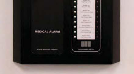
17 Combination Alarm Displays & Functions Audible alarm buzzer Remote signal (master) module Power on indicator History button Alarm test button Master labels ID slot Color coded gas identification label Room ID label slot Gas (Area) Module Program mode indicator Remote signals abnormal status LEDs - Red Digital pressure display Units of measure indicator PSI, In Hg, Bar, or kpa Status code LED s Programming display for remote signal (master) circuit board Remote signals normal status LEDs - Green
18 Alarm Displays & Functions Gas Module (Area alarms) Pressure Reading Display The LED Digital Pressure Display displays the pressure as indicated by the transducer. The gas pressure may be displayed in PSIG/In Hg, BAR or kpa. PSIG and In Hg is the factory setting. Note: Vacuum & EVAC / WAGD are actually displayed as inches of Hg in the PSI mode. In kpa mode the Nitrogen gas display indicates one tenth of the actual pressure when the pressure exceeds 999 kpa (i.e kpa is displayed as 110 and the kpa and (x 10) LED is lit. Note: Alarm settings are maintained even if power is interrupted. Units of Measure Indicator The Units of Measure Indicator illuminates PSIG/In Hg, BAR or kpa (whichever is selected during programming PSIG and In Hg is factory setting) providing the unit of measure displayed on the LED pressure reading. In the kpa mode the Nitrogen gas display indicates one tenth of the actual pressure when the pressure exceeds 999 kpa (i.e kpa is displayed as 110 and the kpa and (x 10) LED is illuminated). High / Normal / Low Status Lights Should the line pressure of a gas exceed the programmed alarm set points for low or high line pressure, the corresponding low or high line pressure LED will be illuminated simultaneously with the buzzer sounding to announce an alarm condition has occurred. When the line pressure is neither high nor low it is considered within the normal range and the green Normal LED is illuminated. These indications are relative to the high and low pressure set points which have been programmed into the alarm. These high and low set points should be set in accordance with NFPA 99 and CSA Z305.1 at 20% of the normal operating pressure. System LED The System LED illuminates in the event of a system problem or malfunction. The following codes will be displayed when a System Error or Failure is detected, or when the History button is pressed: Code Error 0 No error (History only) 1 Flash EE corrupt, defaults loaded 2 Sensor: open or broken line 3 Sensor: com timeout, data not received when expected 4 Sensor: Noise on line, or data errors 5 Sensor: Gas type/range mismatch Actual low psig Low pressure (History only) Actual high psig High pressure (History only) Remote Signal Status LED s (Master Module) Normal Status Light (Green) The normal green status light when illuminated signifies that the equipment being monitored is not in an alarm condition. Abnormal Status Light (Red) The abnormal status light when illuminated signifies that the equipment being monitored is in an alarm condition. Note: If no LED is illuminated the remote signal status LEDs have probably been set in the disabled or off position. This can be verified by placing the Remote Signal circuit board in the programming mode and pressing the to view the status of the remote signal point in question or by simply pressing the Test button to verify that the LED s are functional. Program Mode When a circuit board is placed in the program mode (see Programming Modules page 23) the board may be re-programmed. The brightness level of the circuit boards other than the one in the program mode is decreased. In addition, on Gas Displays (Area Modules) the PGM (Program) LED is illuminated, on Remote Signal Displays (Master Modules) the first Remote Signal point will blink
19 Alarm Operation This section deals with the daily operational aspects of the alarm panel. The Programming the Alarm section covers the procedures to follow in order to configure the alarm if the preprogrammed settings are not appropriate, a module is added or deleted or if the alarm is being incorporated into a T-Net system. After installation has been completed and the alarm has been properly configured, it is ready for operation. Master Alarm Panels Remote Signal (Master) Module With electrical power applied to the alarm, it will monitor the status of the medical gas distribution system and the remote equipment connected to it. The remote signals (master) module displays (via LED indicators) the normal/abnormal status of the remote equipment connected to the alarm. All alarm panels are pre-programmed upon leaving the factory to monitor normally closed signals (per NFPA 99 or CSA ). In normal operation all active signals will be green. Whenever an abnormal status signal is detected the corresponding green LED will be extinguished and the red LED will illuminate. Simultaneously an audible alarm will sound. Pressing the Silence button silences the audible alarm (the Red LED continues to be lit). The appropriate personnel should be notified immediately of the alarm condition. When the alarm condition has been rectified the Red LED is automatically extinguished and the Green LED illuminates. Note: master alarm signals do not repeat only area (gas) modules are equipped with the Repeater Delay feature. Silencing the Alarm Press the Silence button when the alarm is sounding and the alarm will be silenced. Testing the Alarm Pressing and holding the Test button initiates a self-test of the alarm. All LED s and seven segment displays will illuminate for as long as the Test button is depressed. In addition the buzzer will sound. If any LED or seven segment display does not illuminate it is faulty and the circuit board should be replaced. If the buzzer does not sound, it is faulty and the circuit board should be replaced. Note: The alarms (both Area & Master) are programmed to ignore transient signals that are less than 0.7 seconds in duration. Area Alarm Panels Gas Modules With the electrical power applied to the alarm and the gas systems adequately pressurized, the following indicators are illuminated: 1) the Power On LED, 2) the pressure readings of the gas on each gas display, 3) the Normal LED (green) on each gas display. If the pressure of one of the gases drops below the programmed low limit setting, the following events take place simultaneously: 1) the Normal LED will be extinguished, 2) the Pressure Low LED (red) will illuminate, 3) an audible alarm will sound. If the pressure of one of the gases rises above the programmed high limit setting, the following events take place simultaneously: 1) the Normal LED will be extinguished, 2) the Pressure High LED (red) will illuminate, 3) an audible alarm will sound. Silencing the Alarm Press the Silence button when the alarm is sounding and the alarm will be silenced. The area alarm is equipped with a Repeater Delay feature which monitors only the Gas Module (Area) alarms. The Repeater Delay has been factory programmed to make the alarm re-sound every 10 (ten) minutes as long as the alarm condition exists. Note: Remote Signal (Master) alarms are not monitored by the Repeater Delay.


 Pressure Actual High pressure (history only)")
20 Alarm Operation System Alarm The audible buzzer will sound, the System Led will illuminate and an Error Code Err will be displayed on the digital pressure display when a system failure occurs or the history button is depressed. The System LED and Err will illuminate and flash on and off and alternate with a number (per table below) being displayed on the digital display. Note: If Err should be displayed on the Gas Pressure Display of any gas module, this indicates a problem. Some possible problems and corrective actions are: The transducer is not connected to the Gas Module. To correct, check the transducer connection to the back side of the Gas Module. A transducer for a different gas service has been connected to the Gas Module. To correct, check the transducer and the Gas Module gas identification labels and make sure they match. If the above corrective actions do not correct the problem, contact the factory for assistance. Code Error 0 No error (history only) 1 Flash EE corrupt, defaults loaded 2 Sensor: Open or broken line 3 Sensor: Com timeout, data not received when expected. 4 Sensor: Noise on line, or data errors 5 Sensor: Gas type/range mismatch Actual Low pressure (history only) Pressure Actual High pressure (history only) Pressure PGM notification The PGM (program mode) LED will flash off & on when a gas module circuit board is manually placed in the program mode. It is important to note that while a gas module is in the program mode, it is not monitoring the medical gas pipeline. See the Programming the Alarm section of this manual for instructions on programming the gas module.
 Gas Board Program")
 Board Green LED Normal Remote signal indicators Red LED Abnormal Remote signal indicators")
21 Programming the Alarm Button Label Up button Toggle button Down button Save button Silence button Test button Clear button History button Gas Board (back view showing dip switch DIP Switch PGM/RUN (Only outer switch labeled PGM/RUN should be used) Gas Board Program mode indicator Digital pressure display Units of measure LEDs SYSTEM LED HIGH Line Pressure LED NORMAL Line Pressure LED LOW Line Pressure LED Remote Signal (Master) Board Green LED Normal Remote signal indicators Red LED Abnormal Remote signal indicators Programming Display LED
22 Programming the Alarm The alarm has been programmed at the factory prior to shipment. Programming of the alarm may be necessary if: a) the high or low pressure limits for a gas need to be modified b) if a future gas module is being put into service for an added gas service c) if a gas service is being deleted d) if a gas service is being changed e) if a remote signal alarm point needs to be re-configured f) if a remote signal module is being added in the place of a blank module g) if the alarm identification number needs to be changed h) you wish to change the repeater delay time i) you wish to change the units of measure from psig and In Hg to either BAR or kpa j) the alarm panel is being set up on the T-Net system Note: Only authorized personnel should program the alarm! It is important to note that while the alarm is in the program mode, it is not monitoring the medical gas system and alarm conditions will not trigger an alarm. Accessing the Alarm Program Mode To program the alarm, the circuit boards must be placed individually, one at a time in the program mode. To place a circuit board in the programming mode, the dip switch located on the back side of the circuit board to be re-programmed must be changed from the run to the pgm position. After this is done, the gas module (area) board being reprogrammed will be brighter than the rest of the gas module (area) boards (when viewed from the front) and the yellow PGM LED indicator will be flashing to indicate that the alarm is in the program mode and the board which is illuminated more brightly and has the flashing PGM LED is ready to be reprogrammed. The remote signal (master) board being reprogrammed will have the top (first) signal point flashing and the programming display LED s (at the bottom of the board) will illuminate displaying either an O (open circuit) or a C (closed circuit) or a d (disabled). The programming buttons, located on the front of the alarm, upper left corner (see photo on page 22) may now to be used to make the needed program changes. When you have successfully accessed the program mode, it is important to note that some of the buttons revert to their sub-functions: When programming a gas (area) module: The UP key is used to raise the pressure set point and / or to toggle upward thru the list of sub- options. The DOWN key is used to lower the pressure set point and / or to toggle downward thru the list of suboptions. The RIGHT key is used to toggle (scroll) thru the list of major options. The LEFT key is used to SAVE the new programming options after they are selected. When programming a remote signal (master) module: The UP key is used to toggle between the choices of the green LED or the red LED or both the green & reds illuminated (disabled). The DOWN key is used to toggle between the choices of the green LED or the red LED or both the green & reds illuminated (disabled). The RIGHT key is used to toggle (scroll) down to the next remote signal point. The LEFT key is used to SAVE the new programming options after they are selected. Note: In order to perform any of the following programming features you must first set the alarm in the program mode. Programming the High & Low Gas Pressure set points Immediately upon entering a gas module (area) board in the program mode, the high line pressure set point major option is displayed. If the gas module being programmed is a typical 50 psig delivery pressure gas, the board has been pre-programmed at the factory with the high line pressure set point at 60 psig, so the display should show the number 60. If you wish to raise or lower this setting, simply use the up or down keys to adjust the pressure setting.
23 Programming the Alarm After the setting has been changed to the new desired setting, press the LEFT key (SAVE) to save the new setting. Note: if the SAVE LEFT key is not pressed after making the change to the programming and before pressing any other keys, the new setting will not be saved and the alarm will revert to the previously saved setting(s). When the SAVE key is depressed, three horizontal dashes will appear in the display. Press the key to move on to the low line pressure and repeat the above procedure. Note: The alarm is designed with a safety feature so that the high and low set points must be at least 0.5 (psig / in Hg), 0.05 (bar) or 5 (kpa) increments apart. The high set point will not be able to be set below the low set point and visa versa. Programming the Remote Signal (Master) Alarm Points While in the program mode, the top signal point LED will be blinking. At the bottom of the same remote signal board, the Programming Display LED set will display the contact state for the blinking signal point. O = open, C = closed and d = disabled. The contact point that is flashing is capable of being reprogrammed. (Note: in compliance with NFPA 99 or CSA ), all contacts are programmed as closed contact equals a normal condition from the factory). If it is necessary to re-program a signal point; press the key to view the next Remote Signal Alarm Point, when the desired Remote Signal (Master) point is flashing, use the or keys to alter the point to the desired status, after the desired change is achieved, press the to save the change. Note: Any contact point that has been disabled will have both the green (normal) and red (alarm) LED illuminated only when in the programming mode, to make it easy to identify them. In the normal mode of operation, both LED s of a disabled signal point will not illuminate nor will this signal point trigger an alarm. Note: When an alarm condition occurs the audible buzzer sounds simultaneously with the corresponding red LED illuminating and the green corresponding LED being extinguished. When the silence button is depressed, the audible buzzer is silenced and remains silenced until another alarm condition occurs. Master alarm signals do not repeat. Programming the Gas Alarm Repeater Delay After placing a gas board in the program mode, press until dly is displayed on the digital display of the gas module then let go of the key. A number will be displayed on the digital display. This number is the setting (in minutes) of the repeater delay. Using the or keys, adjust the repeater delay to the desired length of time (0 240 minutes). (Note: the repeater delay is pre-programmed from the factory at 10 minutes per NFPA 99 or CSA ). To save the change and return the alarm to the normal alarm mode, press the button, then change the dip switch back to the run setting. Note: this procedure must be repeated for all gas boards on the alarm panel. Note: master alarm signals do not repeat Note: If a value of 0 (zero) is programmed and saved for any board, the repeater is disabled. If left programmed this way after 72 hours, the board(s) will automatically revert back to the preprogrammed factory setting of 10 minutes. Programming the Units of Measure Displays While in the program mode, press the button until -U- is displayed on the digital display of the gas module then let go of the key. The letters PSI or ba or PA will be displayed on the digital display. This is the unit setting that the gas board is set to display. If you wish to alter the unit display, use the or keys to select the desired unit display, then press the SAVE key. Note: this procedure must be repeated for all gas boards on the alarm panel. Note: Vacuum & EVAC / WAGD Gas Modules will automatically display in in/hg when PSI is selected. Note: The kpa and x10 LED s will both illuminate on all high delivery pressure Gas Modules (i.e. Nitrogen and High Pressure Air) when kpa is selected. Because the Gas Pressure LED Display is only able to display three digits and high delivery pressures viewed in kpa are four digits, the Gas Pressure LED must be read as a four digit number by multiplying the displayed number by ten. I.E. the Gas Pressure LED Display is displaying 125 in kpa. The pressure should be read as 1,250 kpa (125 x 10).
24 Programming the Alarm Adjusting the Digital Line Pressure The digital line pressure may be adjusted slightly (per the chart below) by following the simple procedure below. This can be done by one person at the alarm panel no need to open/adjust the transducers! 1. Put the gas module you want to adjust into the PROGRAM MODE. 2. Using the TOGGLE (right arrow) button go to the CAL mode. 3. Use the UP ARROW button to increase the pressure reading and the DOWN ARROW to decrease the pressure reading. The adjusted reading will be displayed as the changes are made. 4. Press the SAVE button (left arrow) to save the setting. 5. You can return to the original calibration setting by pressing CLEAR then press the SAVE button (left arrow) while at CAL in the PROGRAM MODE. This should be done if a transducer is ever replaced, as the reading offset will be applied to the new transducer readings. Range of adjustment: VAC or EVAC /WAGD ± 0.5 In hg 100 psig transducers ± 2.5 psig 250 psig transducers ± 6.0 psig Programming the Board Identification # Note: This feature is only used when the alarm is used in conjunction with a Class1 Inc. T-Net system. Note: Each gas and master (remote signal) circuit board must have a unique Identification Number no two can share the same number. After placing a gas board in the program mode, press until Cld is displayed on the digital display of the gas module then let go of the key. A number will be displayed on the digital display. This number is the board identification # assigned to that circuit board. Using the or keys, select the desired board identification #. Use the SAVE button when you are finished. Note: Each gas and master (remote signal) circuit board must have a unique Identification Number no two can share the same number. Note: Valid identification numbers are The alarm is pre-programmed at the factory with 0 (zero) as the zone identification number. Adding/Removing Modules or Changing the Gas Service of a Gas Board To remove either a gas board or a remote signal master board from an alarm you simply need to turn off the power to the alarm panel (using the switch on the outside of the power supply in the back box), unplug the ribbon cable from the board being removed and then turn the power back on. The alarm will automatically reset itself. To add a remote signal master board to an alarm you follow the same instructions above. Note: The following feature is only used if; an additional gas service is being added to an area alarm, a future gas module is being set up for a new gas service or and existing gas module board is being changed to a different gas service. The gas boards are pre-programmed for a specific gas service from the factory. After placing a gas board in the program mode, it is possible to change the gas service of the board. The following list cross references the number that is actually displayed on the gas board numeric display with the full names of the gases: Gas # displayed Gas service Transducer type 12 Nitrogen Oxygen Nitrous oxide CO2 or CO2-O2 mix Medical Vacuum Wagd / AGSS Medical air Helium or Heliox 100 H16 High pressure air 250 H24 Hyperbaric oxygen 100 H08 Medium pressure 100 carbon dioxide SP Gas mixture 100 HSP High Pressure gas mix 250 3SP Tri-Gas 100

25 T-Net Interface Circuit Board Installation Class1 Inc. DU/DC series alarms may be ordered without T-Net Interface Circuit boards. The T-Net Interface Circuit boards may be installed later. The toggle switch on the front of the power supply should be placed in the OFF position. You will be installing one of three types of interface circuit boards, bracket and cable connector; RS485, Ethernet or Wireless. The Ethernet Interface board is shown here left and the Wireless board is shown here right. Any of the three types installs into the bottom right corner of the alarm back box. The wireless antenna drops thru a hole in the bottom of the back box. The bracket mounts to the existing flange nut. The cable must be installed into the socket on the Button Board properly per the instructions on the cable. All of the gas boards and remote signal (master boards) will need to be reprogrammed with a unique identification number and set up in the T-Net software per the T-Net installation instructions provided with the T-Net software. The power may now be restored to the alarm. The alarm is fully functional even if the T-Net software is not yet installed or is out of service.
 may be installed later, replacing the standard remote signal circuit board(s).")
 Board page 13 the building management interface circuit boards (MCP boards) are wired the")
26 Building Management Interface (MCP) Board Wiring Class1 Inc. DU/DC series alarms may be ordered with standard remote signal circuit board(s) or with building management interface circuit board(s). The building management interface circuit board(s) may be installed later, replacing the standard remote signal circuit board(s). It is only necessary to install building management interface board(s) in one of the master alarm panels. The toggle switch on the front of the power supply should be placed in the OFF position. Output connections to building management system Refer to Wiring Remote Devices to Remote Signal (Master) Board page 13 the building management interface circuit boards (MCP boards) are wired the same way as the standard remote signal circuit boards. The additional two sets of connection terminal are the connection points for the wires outputting the signal information to the building management system. Input connections from remote signal devices The connector terminals may be un-plugged from the circuit board to simplify installation of the remote signal wires. There is no need to remove the wires, simply unplug the connectors from the standard remote signal board and plug them back into the new building management interface circuit board. Be certain to match the label on the socket with the label on the plug. The additional connector terminals are labeled 1 OUT thru 16 OUT and are located on the left edge of the new building management interface circuit board. These correspond with the pairs labeled 1 IN thru 16 IN on the right edge of the circuit board. The NC labeled terminal of each pair is where the signal wire should be landed. The C labeled terminal of each pair is where the common wire should be landed.
27 Appendix A Glossary of Terms AC DC Alternating Current An electric current that reverses direction or polarity at regular intervals. Direct Current An electric current that flows in one direction. The current can be steady or pulse. IN Hg Inches of Mercury A measurement of the force in a gas vacuum system. 1 IN Hg = 3.38 kpa. KPa LED Kilopascals A measurement of the force in a compressed gas system. 1 kpa =.14 PSI Light Emitting Diode A semiconductor diode that converts applied voltage to light. NFPA National Fire Protection Association The National Fire Protection Association is an association engaged in standards development. NO Normally Open An electrical circuit in which the switch is normally open. No current flows through the circuit in normal operation. Only when the switch is closed is the flow of current started. NC PSI V Normally Closed An electrical circuit in which the switch is normally closed. Current flows through the circuit in normal operation. Only when the switch is opened is the flow of current stopped. Pounds per Square Inch A measurement of the force in a compressed gas system. 1 PSI = 6.9 kpa Transducer A device that converts pressure into an electrical signal. Voltage Voltage is electrical pressure or force. One volt is equal to the difference of electrical potential between two points on a conducting wire carrying a constant current of one ampere when the power dissipated between the points is one watt. Transient Signal An intermittent and brief signal that quickly corrects and returns the alarm to a normal operating mode before monitoring personnel can silence the alarm.
28 Appendix B - Medical Gas Alarm Specifications Operating Ambient Temperature range: +10C(50F) to +50C(122F) Storage Temperature: -20C (-4F) to +85C (185F) AC Input: volts AC Hz DC output (to remote signal devices): 5 VDC Input Fuse: 5 amp input AC line fuse protects the input wiring to power supply Power Consumption: 45W maximum Pressure Measurement Accuracy: 0-30 inhg transducer +/-1% Vacuum, Gas Evacuation Dimensions PSIG transducer +/-1% Oxygen, Nitrous Oxide, Medical Air, Carbon Dioxide 0-250PSIG transducer +/-1% Nitrogen Rough-in Box - All dimensions are in inches and cover the basic box only (mounting flange excluded) Two vertical slot panel 8.125W x H x 4.000D Three vertical slot panel W x H x 4.000D Five vertical slot panel W x H x 4.000D Front Panel Two vertical slot panel W x H x 1.250D Three vertical slot panel W x H x 1.250D Five vertical slot panel W x H x 1.250D Transducers: Housing dimensions: 1.990W x 1.990H x Length including inlet fittings
Zone Valve Alarm Combination Systems Installation and Operating Manual
 Zone Valve Alarm Combination Systems Installation and Operating Manual Ver. 2012 - Rev. 1004 Class 1 Inc. design manufacture installation service world class innovation Call us for your next project. Table
Installation & Operating Instructions for Integrated Series Area Alarm Zone Valve Box Systems
 Manufacturer of Medical Gas Pipeline Equipment Installation & Operating Instructions for Integrated Series Area Alarm Zone Valve Box Systems e5536rir 6/15/12 Tri-Tech, 35401 Avon Commerce Pkwy., Avon,
Installation & Operating Instructions for Area, Master & Combination Alarm Systems
 Manufacturer of Medical Gas Pipeline Equipment Installation & Operating Instructions for Area, Master & Combination Alarm Systems Andersen Medical Gas 12 Place Lafitte Madisonville, LA 70447 http://www.themedicalgas.com
Installation & Operating Instructions for Med Touch Series Area, Master & Combination Alarm Systems
 Manufacturer of Medical Gas Pipeline Equipment Installation & Operating Instructions for Med Touch Series Area, Master & Combination Alarm Systems Master Alarm Area Alarm Andersen Medical Gas 12 Place
Installation & Operating Instructions for ZT and EZT Integra Touch Series Area Alarm Zone Valve Box Systems
 Manufacturer of Medical Gas Pipeline Equipment Installation & Operating Instructions for ZT and EZT Integra Touch Series Area Alarm Zone Valve Box Systems e6565rc 05/11/18, 35401 Avon Commerce Pkwy., Avon,
Tri-Tech Medical Inc.
 Submittal Data Sheet Project Information Project Number Approval Features The Tri-Tech Area and Master Alarm Panel digitally displays gas pressure (1 psi increments) monitors and displays normal and alarm
Med Touch Combination Alarm Conversion Kits
 Submittal Data Sheet Features The Powerex Combination Alarm Panel conversion kits are designed to upgrade or retro-fit existing panels produced by several major brands. The conversion kit replaces all
MEGA. cal electronic gas alarm. Installation, Operation, and Maintenance Instructions. Part No Rev. D Pg.
 WARD OXYGEN Installation, Operation, and Maintenance Instructions MEGA medical electronic gas alarm MEGA WARD MEGA medical electronic gas alarm WARD POWER SUPPLY Medical Electronic Gas Alarm OXYGEN SYSTEM
EZT Series Integra Med Touch Area Alarm & Zone Valve Box with EZ Backfeed
 Submittal Data Sheet Features The Powerex Med Touch area alarm zone valve panel digitally displays gas pressure (1 psi increments) and provides alarm conditions as required by the latest edition of NFPA
Integra Med Touch Series LCD Area Alarm & Zone Valve Box Systems
 Please read and save these instructions. Read carefully before attempting to assemble, install, operate or maintain the product described. Protect yourself and others by observing all safety information.
Operating & Maintenance Manual. Alert-4 Ethernet LCD Master Alarm
 Operating & Maintenance Manual Alert-4 Ethernet LCD Master Alarm w w w. a m i c o. c o m Contents User Responsibility 4 Introduction 4 Features 5 Description of the Alarm 5 Shipment Details 5 The Alarm
Installation Instructions for Med-Touch Series LCD Medical Gas Area, Master & Combination Alarms Conversion Kits
 Manufacturer of Medical Gas Pipeline Equipment Installation Instructions for Med-Touch Series LCD Medical Gas Area, Master & Combination Alarms Conversion Kits Master Alarm Conversion Combination Alarm
Installation, Operation, and Maintenance Instructions
 Installation, Operation, and Maintenance Instructions MEGA 2 Medical Electronic Gas Alarm Andersen Medical Gas 12 Place Lafitte Madisonville, LA 70447 http://www.themedicalgas.com 1-866-288-3783 MAN 01-027
Alert-3 LCD Alarm v2.0
 Operating & Maintenance Manual Alert-3 LCD Alarm v2.0 1ST FLOOR ROOM 12 2ND FLOOR ROOM 25 3RD FLOOR ROOM 37 MAINTEN EXT 302 4TH FLOOR ROOM 47 5TH FLOOR ROOM 58 w w w. a m i c o. c o m Contents User Responsibility
Installation and Maintenance Manual. Alarm Valve Combo Unit Alert-1 v1.6
 Installation and Maintenance Manual Alarm Valve Combo Unit Alert-1 v1.6 Table of Contents User Responsibility 4 Introduction 5 Features 5 Installation of Valve Boxes 6 Maintenance and Annual Test 7 Description
Med Touch Master Alarm
 Submittal Data Sheet Features The Powerex Med Touch Master Alarm Panel monitors and displays normal and alarm conditions from up to 128 remote medical gas source signals and provides alarm conditions as
Tri-Tech Medical Inc.
 Submittal Data Sheet Project Information Project Number Approval Features The Master Alarm Panel conversion kits are designed to upgrade or retro-fit existing panels produced by several major brands. The
Pioneer-R16 Gas Monitor Operator s Manual
 Pioneer-R16 Gas Monitor Operator s Manual Edition 7/2/97 RKI INSTRUMENTS, INC RKI Instruments, Inc. 33248 Central Ave, Union City, CA 94587 (510) 441-5656 Chapter 1: Description About the Pioneer-R16 Gas
Operating & Maintenance Manual. Alert-4 Ethernet LCD Master Alarm
 Operating & Maintenance Manual Alert-4 Ethernet LCD Master Alarm Contents User Responsibility 4 Introduction 4 Features 5 Description of the Alarm 5 Shipment Details 5 The Alarm Back Box 5 The Frame/Module
Alert-3 LCD Alarm v2.5
 Operating & Maintenance Manual Alert-3 LCD Alarm v2.5 1ST FLOOR ROOM 12 2ND FLOOR ROOM 25 3RD FLOOR ROOM 37 MAINTEN EXT 302 4TH FLOOR ROOM 47 5TH FLOOR ROOM 58 Contents User Responsibility 4 Introduction
Product Manual SZ1145
 Product Manual SZ114 General Purpose Monitor Communicating Controls Description The SZ114 is a microprocessor-based monitoring and alarm interface designed to monitor up to four 1000 Ω platinum temperature
ANALOX 5001 Carbon Dioxide Monitor. User Manual ANALOX Analox 5001 Carbon Dioxide Monitor User Manual
 ANALOX 5001 ANALOX 5001 Carbon Dioxide Monitor User Manual Analox Sensor Technology Ltd 15 Ellerbeck Court, Stokesley Business Park North Yorkshire, TS9 5PT T: +44 (0)1642 711400 F: +44 (0)1642 713900
Public Safety DAS Annunciator Panel
 Public Safety DAS Annunciator Panel 120 VAC Models: 1221-A, 1221-B, 1221-C Revision D 91117 48 VDC Models: 1221-A-48, 1221-B-48, 1221-C-48 24 VDC Models: 1221A-24, 1221-B-24, 1221-C-24 CAUTION: (Read This
Alert-3 LCD Alarm v2.4
 Operating & Maintenance Manual Alert-3 LCD Alarm v2.4 1ST FLOOR ROOM 12 2ND FLOOR ROOM 25 3RD FLOOR ROOM 37 MAINTEN EXT 302 4TH FLOOR ROOM 47 5TH FLOOR ROOM 58 Contents User Responsibility 4 Introduction
Product Manual SZ1144
 Product Manual SZ1144 Refrigeration Temperature Monitor Communicating Controls Description The SZ1144 is a microprocessor-based monitoring and alarm interface designed to monitor up to four 1000 Ω platinum
Carbon Monoxide Transmitter
 Introduction The CO Transmitter uses an electrochemical sensor to monitor the carbon monoxide level and outputs a field-selectable 4-20 ma or voltage signal. The voltage signal may also be set to 0-5 or
Models NFPA 1221-A, NFPA 1221-B Public Safety DAS Annunciator Panel. Revision E 61117
 Models NFPA 1221-A, NFPA 1221-B Public Safety DAS Annunciator Panel Revision E 61117 CAUTION: (Read This First) This panel has been designed to make it nearly bullet proof to mistakes made when wiring
Caliber Series LED Edgelit Exit Sign EXPORT AC Only or Emergency Operation READ AND FOLLOW ALL SAFETY INSTRUCTIONS
 Caliber Series LED Edgelit Exit Sign EXPORT AC Only or Emergency Operation INSTALLATION AND OPERATING INSTRUCTIONS IMPORTANT SAFEGUARDS When using electrical equipment, basic safety precautions should
Beacon 200 Gas Monitor Operator s Manual. Part Number: RK Released: 6/6/08
 Beacon 200 Gas Monitor Operator s Manual Part Number: 71-2102RK Released: 6/6/08 Table of Contents Chapter 1: Introduction.................................................3 Overview.............................................................3
Refrigeration Controller Operator s Manual (HRC) PO Box 6183 Kennewick, WA
 PO Box 6183 Kennewick, WA") Refrigeration Controller Operator s Manual (HRC) PO Box 6183 Kennewick, WA 99336 www.jmcvr.com 1-509-586-9893 Table of Contents TABLE OF FIGURES...1 OVERVIEW OF THE HRC CAPABILITIES...2 INSTALLATION AND
Refrigeration Controller Operator s Manual (HRC) PO Box 6183 Kennewick, WA 99336 www.jmcvr.com 1-509-586-9893 Table of Contents TABLE OF FIGURES...1 OVERVIEW OF THE HRC CAPABILITIES...2 INSTALLATION AND
Mark 25 Ultrapure Water Conductivity Analyzer
 Martek Instruments, Inc. Mark 25 Ultrapure Water Conductivity Analyzer Instruction Manual WARRANTY POLICY Unless otherwise stated, MARTEK INSTRUMENTS, INC. warrants this equipment to be free from defects
GasScanner 8C. Eight Channel Monitor. Operator s Manual. MINT-0281-XX Rev. A 01/29/08
 GasScanner 8C Eight Channel Monitor Operator s Manual MINT-0281-XX Rev. A 01/29/08 Product Warranty Matheson Tri-Gas, Inc., warrants gas alarm equipment sold by us to be free from defects in materials,
EG-400 Fire Detection Monitor
 EG-400 Fire Detection Monitor For Engine and Generator compartments Owner s manual with installation instructions Revision 2.3 (10/1/07) Our Business is Your Safety and Peace of Mind! Jim Shepherd Toll
Installation, Operating and Maintenance Manual
 STATUS ZONES CONTROLS FIRE FAULT DISABLED FIRE 1 2 3 4 5 6 7 8 TEST FAULT DISABLED 1 5 BUZZER SILENCE RESET 1 2 TEST 2 6 LAMP TEST 3 SUPPLY 3 7 SYSTEM FAULT 4 8 SOUNDERS ACTIVATE/ SILENCE 4 FAULTS INSTRUCTIONS
Tri-Tech Medical Inc.
 Check Valves with Extensions Project Information Project Number Approval Hinged double disc check valve Removable center section (3 piece design) allows for easy field replacement (no cutting into pipe
Duct and Rough Service Carbon Monoxide Sensor
 Product Identification and Overview Duct and Rough Service Carbon Monoxide Sensor BAPI s Carbon Monoxide Sensor offers enhanced electrochemical sensing with outstanding accuracy at low concentrations.
DUKE UNIVERSITY CONSTRUCTION STANDARDS
 1 22 60 00 Gas and Vacuum Systems for Laboratory & Healthcare Facilities 1. General A. Furnish and test the following systems: 1. Oxygen (O2) 2. Vacuum (Vac) 3. Medical/clinical compressed air (MA) 4.
Lubrication cycle IP Enclosure Rating. 110 VAC, 220/230 VAC (50/60 Hz) Alarm Fault Relay Contacts. IP-55 (Liquid tight connector)
 Alarm Fault Relay Contacts. IP-55 (Liquid tight connector)") SMAC Controller Industrial Lubrication Systems Operation The SMAC Controller is a multi-purpose programmable controller used with industrial lubrication systems. Controller settings are saved whenever
SMAC Controller Industrial Lubrication Systems Operation The SMAC Controller is a multi-purpose programmable controller used with industrial lubrication systems. Controller settings are saved whenever
ZX1e ZX2e ZX5e. Document No Issue 01 user manual
 ZX1e ZX2e ZX5e Document No. 996-130 Issue 01 user manual MORLEY-IAS ZX2E/ZX5E Fire Alarm Control Panels Table of Contents 1 INTRODUCTION... 4 1.1 NOTICE... 4 1.2 WARNINGS AND CAUTIONS... 4 1.3 NATIONAL
MODEL 5100 VOTING LOGIC MODULE
 DESCRIPTION DESCRIPTION The SST Model 5100 Multi-Input Voting Logic Module is used to monitor the status of up to 14 different points in a hazard zone, and report when a selectable number of these points
INSTALLATION GUIDE Dual Fuel Ranges
 INSTALLATION GUIDE Dual Fuel Ranges Contents Wolf Dual Fuel Ranges......................... 3 Safety Instructions............................ 4 Dual Fuel Range Specifications.................. 5 Dual Fuel
OPERATION & INSTALLATION MANUAL FOR ALARM PANEL M2AP01
 OPERATION & INSTALLATION MANUAL FOR ALARM PANEL M2AP01 Table of Contents Safety Instructions 4 Owner/Operator Responsibility 4 Specifications 5 Introduction 6 Installation Instructions 7 Setup 7 Wiring
Installation and user manual for the FX range of fire panels. 1, 2, 4 and 8 zone panels
 Installation and user manual for the FX range of fire panels 1, 2, 4 and 8 zone panels Contents Panel installation 3 Panel connections 3 Wiring connection drawings 4 Panel facilities 6 Installation check
OPERATING AND MAINTENANCE MANUAL. for the G30 CARBON DIOXIDE MONITOR
 OM117 OPERATING AND MAINTENANCE MANUAL for the G30 CARBON DIOXIDE MONITOR (Part No: G30) (Intentionally Blank) APPROVAL SHEET DIVEX MANUAL NUMBER: ADVITIUM NUMBER: DOCUMENT TITLE: OM117 GA-OM-5715 G30
RTD TEMPERATURE SENSING SYSTEM
 General Overview RTD TEMPERATURE SENSING SYSTEM The Prime Technology RTD Temperature System 9219-00-0002 is a three-channel temperature measuring system that utilizes two RTD Temperature Sensor inputs
NX-148 LCD CODE PAD TABLE OF CONTENTS
 NX-148 LCD CODE PAD TABLE OF CONTENTS Glossary Of Terms... 4 Understanding The Lights... 5 Code Pad Functions Arming In The ON Mode... 6 Making The System Ready To Arm... 7 Using Quick Arm... 7 Arming
CORNELL Emergency Response Systems
 CORNELL Emergency Response Systems Door Monitor Systems Series 1000 CORNELL Communications, Inc. Milwaukee, WI USA 800-558-8957 - www.cornell.com rev 6/04 A-1000 SERIES DOOR MONITOR OPERATION AND WIRING
Safe T Net 210. Instruction Manual Part Number Mar2010
 Safe T Net 210 Instruction Manual Part Number 71-0012 31Mar2010 2007 Thermo Fisher Scientific Inc. All rights reserved. Specifications, terms and pricing are subject to change. Not all products are available
ACSI MODEL 1410 POWER SUPPLY INSTALLATION INSTRUCTIONS
 II 1400-3 ACSI MODEL 1410 POWER SUPPLY INSTALLATION INSTRUCTIONS Features: For use with doors or groups of doors that must interlock with each other to regulate control of accessing one area from another,
Architectural and Engineering Specification for a. Flash / Flare
 Architectural and Engineering Specification for a Flash / Flare June 27, 2014 Page 1 of 12 T1DA0115-001 Rev D This document is intended to provide performance specifications and operational requirements
Analox 1000 Series. User Manual. Analox Sensor Technology Ltd. 15 Ellerbeck Court, Stokesley Business Park North Yorkshire, TS9 5PT, UK
 Analox 1000 Series User Manual Analox Sensor Technology Ltd. 15 Ellerbeck Court, Stokesley Business Park North Yorkshire, TS9 5PT, UK T: +44 (0)1642 711400 F: +44 (0)1642 713900 W: www.analox.net E: info@analox.net
OHIO MEDICAL CORPORATION. Medical Gas Alarms. Installation and Maintenance Manual. Area Alarm. Master Alarm. Combo Alarm. P/N (Rev.
 OHIO MEDICAL CORPORATION Medical Gas Alarms Installation and Maintenance Manual Area Alarm Master Alarm Combo Alarm P/N 255098 (Rev.8) 07/08 Page 2 NOTES Andersen Medical Gas 12 Place Lafitte Madisonville,
F PC and AO OUTPUT BOARDS INSTRUCTION MANUAL. Blue-White. Industries, Ltd.
 F-2000 PC and AO OUTPUT BOARDS INSTRUCTION MANUAL Blue-White R Industries, Ltd. 500 Business Drive Huntington Beach, CA 92649 USA Phone: 714-89-8529 FAX: 714-894-9492 E mail: sales@blue-white.com or techsupport@blue-white.com
Installation and user manual for the CF5000, MF5000 and FXP5000 range of fire panels
 CF5000, MF5000 and FXP5000 Installation and user manual for the CF5000, MF5000 and FXP5000 range of fire panels 16 zone panels Contents PANEL INSTALLATION...3 Installation...3 PANEL WIRING... 3 Mains power
Operating & Maintenance Manual. Alert-2 Microprocessor Based Digital Alarm System v6.2
 Operating & Maintenance Manual Alert2 Microprocessor Based Digital Alarm System v6.2 Contents User Responsibility 1 Introduction 12 Features 2 Description of the Alarm 3 Shipment Details 3 The Alarm Back
Beacon 800 Gas Monitor Operator s Manual
 Beacon 800 Gas Monitor Operator s Manual Part Number: 71-0037RK Revision: F Released: 4/18/17 www.rkiinstruments.com Product Warranty RKI Instruments, Inc. warrants gas alarm equipment sold by us to be
FEC400 Series. Installation Manual
 FEC400 Series Conventional microprocessor controlled fire detection and alarm panels with extinguishing control Installation Manual Version 2.3 / August 2004 Aritech is a GE Interlogix brand. http://www.geindustrial.com/ge-interlogix/emea
Operating & Maintenance Manual. Alert-2 Microprocessor Based Digital Alarm System v6.3
 Operating & Maintenance Manual Alert2 Microprocessor Based Digital Alarm System v6.3 Contents User Responsibility 1 Introduction 12 Features 2 Description of the Alarm 3 Shipment Details 3 The Alarm Back
RANGER 8600 DOWNLOADABLE CONTROL COMMUNICATOR INSTALLATION MANUAL
 RANGER 8600 DOWNLOADABLE CONTROL COMMUNICATOR INSTALLATION MANUAL TABLE OF CONTENTS GENERAL DESCRIPTION... 2 STANDARD AND OPTIONAL PARTS LIST... 2 PARTS DIAGRAM... 3 TERMINAL DRAWING AND SPECIAL NOTES...
User s Manual. TIGER S EYE E-Series Mark V Jockey. TIGERFLOW Systems, Inc Mint Way Dallas, Texas
 User s Manual TIGER S EYE E-Series Mark V Jockey TIGERFLOW Systems, Inc. 4034 Mint Way Dallas, Texas 75237 214-337-8780 www.tigerflow.com TABLE OF CONTENTS Introduction... 4 Sequence of Operation... 5
INTELLIGENT FIRE TECHNOLOGY. Twinflex and Multipoint V3. User Guide (TO BE RETAINED BY USER) Issue 3
 Issue 3") INTELLIGENT FIRE TECHNOLOGY Twinflex and Multipoint V3 User Guide (TO BE RETAINED BY USER) 26-0340 Issue 3 Rafiki Protection Limited Rafiki policy is one of continual improvement and the right to change
INTELLIGENT FIRE TECHNOLOGY Twinflex and Multipoint V3 User Guide (TO BE RETAINED BY USER) 26-0340 Issue 3 Rafiki Protection Limited Rafiki policy is one of continual improvement and the right to change
Operation & Maintenance Manual
 Operation & Maintenance Manual for Model 2100 Fire+Smoke systems from Smoke Guard, Inc. 287 N. Maple Grove - Boise, ID 83704 Phone: (800) 574-0330 Fax: (208) 639-7851 E-Mail: info@smokeguard.com Website:
Series DCT1000DC Dust Collector Timer Controller Specifications Installation and Operating Instructions
 Series DCT1000DC Dust Collector Timer Controller Specifications Installation and Operating Instructions Bulletin E-97DC Thank you for purchasing the Dwyer DCT1000DC Dust Collector Timer Controller. You
SEC 2000 Millenium Infrared Gas Detector
 SEC 2000 Millenium Infrared Gas Detector Instruction and Operation Manual Sensor Electronics Corporation 5500 Lincoln Drive Minneapolis, Minnesota 55436 USA (952) 938-9486 Fax (952) 938-9617 Email: sales@sensorelectronic.com
1 4 DIN Dissolved Oxygen Controller
 16. Warranty OAKTON warrants this controller to be free from significant deviations in material and workmanship for a period of one year from date of purchase. If repair or adjustment is necessary and
Analog Room Pressure Monitor RPC Series
 Description The Room Pressure Monitor is used to measure differential pressure in the range of 0.125 to 1"wc or 30 to 250 Pa. It combines precision high sensitivity silicon sensing capabilities and the
Conventional Releasing Control Panel
 s Data Sheet Fire Safety Products Conventional Releasing Control Panel Pre-Action Deluge Agent-Releasing Fire System Model TXR-320 Remote configurable Up to two (2) hazard areas Operable with the following:
Installation Instructions for Med Touch Master Alarms - Wireless
 Installation Instructions for Med Touch Master Alarms - Wireless Master Alarm Panel Local Sending Master Alarm Panel - Master Alarm Panel - Repeater Page 1 of 7 Common Master Alarm Back Box Assembly Assembling
RAPID RESPONSE Model RCP-1 Residential Control Panel 1 or 1-1/2 Inch (DN25 or DN40), 175 psi (12,1 bar) General Description
, 175 psi (12,1 bar) General Description") Worldwide Contacts www.tyco-fire.com RAPID RESPONSE Model RCP-1 Residential Control Panel 1 or 1-1/2 Inch (DN25 or DN40), 175 psi (12,1 bar) SECTIONS General Description.... 1 Warnings.... 2 Technical
Worldwide Contacts www.tyco-fire.com RAPID RESPONSE Model RCP-1 Residential Control Panel 1 or 1-1/2 Inch (DN25 or DN40), 175 psi (12,1 bar) SECTIONS General Description.... 1 Warnings.... 2 Technical
SPECIFICATION: AlarmLine TM INTELLIGENT LINEAR HEAT DETECTION
 1. GENERAL SPECIFICATION 1.1 The contractor shall provide an Intelligent AlarmLine Linear Heat Detection System to perform the following functionality: A. Fire Alarm, Supervisory and Trouble-Event Initiation
TrueCom. Building Communications Systems 5115-Series , Area of Rescue Communications System. Description
 TrueCom Building Communications Systems 5115-Series 5115-9001, -9002 Area of Rescue Communications System Description The Simplex 5115-9001 and -9002 Area of Rescue Communications System provides buildings
Control/Communicator Installation Manual
 DAS NETWORX NX-12 Control/Communicator Installation Manual General Description...2 Ordering Information...2 Option Definitions...3 Programming the LED Code Pads...5 Programming the NX-12...9 Types of Programming
Dryer Controller M720
 User Manual Dryer Controller M720 Hardware version 2.00 Software version 2.00 Manual M720 Dryer controller Page 1 of 60 Document history Preliminary version: - Created in April, 2009 Hardware Version 2.00,
RAPID RESPONSE Model RCP-1 Residential Control Panel 1 or 1-1/2 Inch (DN25 or DN40), 175 psi (12,1 bar) General Description.
, 175 psi (12,1 bar) General Description.") Worldwide Contacts www.tyco-fire.com RAPID RESPONSE Model RCP-1 Residential Control Panel 1 or 1-1/2 Inch (DN25 or DN40), 175 psi (12,1 bar) General Description The TYCO RAPID RESPONSE Model RCP-1 Residential
Worldwide Contacts www.tyco-fire.com RAPID RESPONSE Model RCP-1 Residential Control Panel 1 or 1-1/2 Inch (DN25 or DN40), 175 psi (12,1 bar) General Description The TYCO RAPID RESPONSE Model RCP-1 Residential
GASGUARDIAN Channel Controller OPERATING & INSTALLATION MANUAL
 GASGUARDIAN 2 3 2-Channel Controller OPERATING & INSTALLATION MANUAL GasGuardian 2 3 Operating and Installation Manual Table of Contents General description.... 3 Installation. 3 Locating the GasGuardian-2..
CPS-1 USER S MANUAL AIR INLET / CURTAIN CONTROL
 CPS-1 USER S MANUAL AIR INLET / CURTAIN CONTROL temperature / static pressure DIFF Opn Clo ALARM HI F2 DELAY ALARM LO OPEN DELAY CLOSE ADJUST Varifan + CPS-1 CPS-1 Although the manufacturer has made every
DET-TRONICS SPECIFICATION DATA. Eagle Quantum EQ2200UVHT For Use With C7050B Continuous Duty High Temperature UV Flame Detector DESCRIPTION
 DET-TRONICS SPECIFICATION DATA Eagle Quantum EQ2200UVHT For Use With C7050B Continuous Duty High Temperature UV Flame Detector DESCRIPTION The EQ2200UVHT UV Flame Detector is used with the Eagle Quantum
Replaceable LED modules. Sleep or unattended mode. Auto-silence and auto-acknowledge
 Replaceable LED modules 11 Alarm Sequences as per ISA-18.1 standard Each channel/window fully field programmable RS232 or RS485 MODBUS-RTU communication Repeat relay for each window and multifunction relays
PNC 1000 SERIES 2, 4, 8 Zone Fire Alarm Control Panel
 PNC 1000 SERIES 2, 4, 8 Zone Fire Alarm Control Panel INSTALLATION, OPERATION AND MAINTENANCE MANUAL Version: CN-PM-1000.VER1.1-12/2012 EN54 INFORMATION In accordance with EN 54-2 clause 13.7, the maximum
AS DIGITAL FIRE PUMP CONTROLLER
 AS 2941-2013 DIGITAL FIRE PUMP CONTROLLER COMPLIANT WITH AS2941-2013 CLAUSES 9.4.1 9.4.22 OPERATION INSTRUCTIONS New South Wales Unit 2/1040 Canley Vale Road Wetherill Park NSW 2164 Ph: +61 2 9757 5800
DE5300 Delayed Egress System. General Information
 *911031-00* 911031-00 Wiring and Configuration DE5300 Delayed Egress System Installation Instructions General Information The Von Duprin DE5300 is designed for controlled egress applications when used
Control Panel User Guide
 Fire Detection & Alarm System Control Panel V4.14 Control Panel User Guide (TO BE RETAINED BY USER) 26-0397 Issue 6 Fike s policy is one of continual improvement and the right to change a specification
ACCURATE ELECTRONICS INC PO BOX SW HALL BLVD BEAVERTON OR USA FAX
 Page 1 of 10 Model 10807800 January 2014 ACCURATE ELECTRONICS INC PO BOX 1654 97075-1654 8687 SW HALL BLVD 97008 BEAVERTON OR USA 503.641.0118 FAX 503.646.3903 WWW.ACCURATE.ORG Practice Section 10807800
Dual Technology Wall Switch Occupancy Sensor. Manual & Specification
 Dual Technology Wall Switch Occupancy Sensor Manual & Specification PRODUCT MUST BE INSTALLED IN ACCORDANCE WITH LOCAL ELECTRICAL CODES Douglas Lighting Controls Page 1 November 19, 2014 1. INTRODUCTION
Remote Chexit Module (RCM) System. General Information
 System. General Information") *911032-00* 911032-00 Wiring and Configuration Remote Chexit Module (RCM) System Installation Instructions General Information The Von Duprin RCM is designed for controlled egress applications. It meets
*911032-00* 911032-00 Wiring and Configuration Remote Chexit Module (RCM) System Installation Instructions General Information The Von Duprin RCM is designed for controlled egress applications. It meets
Destiny Destiny Owners Manual
 Destiny 4100 Destiny 4100 Owners Manual TABLE OF CONTENTS INTRODUCTION Control Panel...3 Detection Devices...3 Telephone Keypads...3 GLOSSARY... 4-5 LOCAL PHONE ACCESS Using Your Telephones As Keypads...6
Operating instructions 2-channel code lock. Item No
 Operating instructions 2-channel code lock Item No. 1560346 Table of contents Page 1. Introduction...4 2. Explanation of symbols...4 3. Intended use...5 4. Delivery content...5 5. Safety instructions...6
Pump-Down Controller MODEL 4052
 Pump-Down Controller 4-20mA Input/Scalable Output Seal Fail Monitoring Duplex Pump Alternation Hand-Off-Auto Controls Dual Run-time Meters RS-485/Modbus Communications DESCRIPTION The Model 4052 Pump-Down
RANGER 7600 DOWNLOADABLE CONTROL COMMUNICATOR INSTALLATION MANUAL
 RANGER 7600 DOWNLOADABLE CONTROL COMMUNICATOR INSTALLATION MANUAL TABLE OF CONTENTS 1. TABLE OF CONTENTS... P.1 2. GENERAL DESCRIPTION... P.2... 3. STANDARD AND OPTIONAL PARTS LIST... P.2... 4. FEATURE
DENVER PUBLIC SCHOOLS DESIGN AND CONSTRUCTION STANDARDS This Standard is for guidance only. SECTION IBAS LIGHTING CONTROL
 PART 0 A/E INSTRUCTIONS 0.01 DESIGN REQUIREMENTS A. Minimum lighting control (base scope of work) shall include all corridors. The lighting in all the corridors shall be turned on (if not already on) if
GG-2 2-CHANNEL GAS DETECTION CONTROL PANEL. Installation and Operation Manual
 GG-2 2-CHANNEL GAS DETECTION CONTROL PANEL Installation and Operation Manual 2 GG-2 Warning Use this product only in the manner described in this manual. If the equipment is used in a manner not specified
v3 360 Dual Technology Low Voltage Occupancy Sensor with Light Level, Isolated Relay and Manual On feature
 DT-300 v3 360 Dual Technology Low Voltage Occupancy Sensor with Light Level, Isolated Relay and Manual On feature Specifications Voltage...18-28VDC/VAC, half wave rectified AC Current Consumption...25
DESCRIPTIVE AND INSTALLATION INSTRUCTION MANUAL FOR MODEL G1000 AND H1000 SERIES ANNUNCIATORS
 DESCRIPTIVE AND INSTALLATION INSTRUCTION MANUAL FOR MODEL G1000 AND H1000 SERIES ANNUNCIATORS SEEKIRK, INC. 2420 Scioto Harper Dr. Columbus, OH 43204 Tel: (614) 278-9200 FAX: (614) 278-9257 email: seekirk@seekirk.com
Owner s Manual. Walk-in Monitoring System 100B. Cooler is Better! TM. Used in UL Listed Door Panel Assemblies
 REV. E Cooler is Better! TM Owner s Manual Walk-in Monitoring System 100B Used in UL Listed Door Panel Assemblies American Panel Corporation 5800 S.E. 78th Street, Ocala, Florida 34472-3412 Phone: (352)
ITC 2000 HEATING CONTROL CABINET. Installation & Operation Manual
 ITC 2000 HEATING CONTROL CABINET Installation & Operation Manual VTI, Incorporated 24 McMillan Way Newark, DE 19713 Phone (302) 738 0500 FAX (302) 738 6594 Revision Level 0.03 Manual No. 90003314 June,
Flopurge TS. Operation Manual
 Flopurge TS Operation Manual Part Number 079-0204 Spectron Gas Control Systems United Kingdom Unit 4, Herald Court, University of Warwick Science Park, Coventry, CV4 7EZ +44 (0)24 7641 6234 sales@spectron-gcs.com
MODEL A-316 CARBON MONOXIDE (CO) MONITOR AND ALARM FOR COMPRESSED AIR TESTING
 MONITOR AND ALARM FOR COMPRESSED AIR TESTING") MODEL A-316 CARBON MONOXIDE (CO) MONITOR AND ALARM FOR COMPRESSED AIR TESTING FOR OPERATION FROM 115 AC POWER Andersen Medical Gas 12 Place Lafitte Madisonville, LA 70447 http://www.themedicalgas.com 1-866-288-3783
MODEL A-316 CARBON MONOXIDE (CO) MONITOR AND ALARM FOR COMPRESSED AIR TESTING FOR OPERATION FROM 115 AC POWER Andersen Medical Gas 12 Place Lafitte Madisonville, LA 70447 http://www.themedicalgas.com 1-866-288-3783
Installation Instructions
 38MHR Outdoor Unit Single Zone Ductless System Sizes 09 to 24 Installation Instructions NOTE: Read the entire instruction manual before starting the installation. NOTE: Images are for illustration purposes
CA5000 Liquid CO 2 Freezer Backup System
 CA5000 Liquid CO 2 Freezer Backup System OPERATING INSTRUCTIONS MANUAL HAMPSHIRE CONTROLS CORPORATION ONE GROVE STREET / P.O. BOX 516, DOVER, NEW HAMPSHIRE USA 03821 TEL. (603) 749-9424 FAX (603) 749-9433
INSTRUCTION MANUAL 4-WAY BALL VALVE Digital Manifold
 LOW VAC INSTRUCTION MANUAL 4-WAY BALL VALVE Digital Manifold REF HIGH SPECIAL FEATURES Low battery indicator Displays 63 refrigerants Displays corresponding saturation, dew or bubble point temperature