Quick Start Guide , Rev CB May Rosemount 3144P Temperature Transmitters with FOUNDATION fieldbus Protocol
|
|
|
- Marvin Shields
- 5 years ago
- Views:
Transcription

1 Quick Start Guide , Rev CB Rosemount 3144P Temperature Transmitters with FOUNDATION fieldbus Protocol
2 Quick Start Guide NOTICE NOTICE This guide provides basic guidelines for the Rosemount 3144P. It does not provide instructions for detailed configuration, diagnostics, maintenance, service, troubleshooting, Explosion-proof, Flameproof, or intrinsically safe (I.S.) installations. Refer to the 3144P Reference Manual (document number ) for more instruction. The manual and this guide are also available electronically on Explosions could result in death or serious injury. Installation of this transmitter in an explosive environment must be in accordance with the appropriate local, national, and international standards, codes, and practices. Review the approvals section of this manual for any restrictions associated with a safe installation. In an Explosion-proof/Flameproof installation, do not remove the transmitter covers when power is applied to the unit. Process leaks may cause harm or result in death. Install and tighten thermowells or sensors before applying pressure. Do not remove the thermowell while in operation. Electrical shock can result in death or serious injury. Avoid contact with the leads and terminals. High voltage that may be present on leads can cause electrical shock. Contents Mount the transmitter Verify transmitter configuration Wire and apply power Set the switches Verify tagging Product Certifications
3 Quick Start Guide Step 1: Mount the transmitter Mount the transmitter at a high point in the conduit run to prevent moisture from draining into the transmitter housing. Typical North America installation 1. Mount the thermowell to the process container wall. Install and tighten thermowells. Perform a leak check. 2. Attach any necessary unions, couplings, and extension fittings. Seal the fitting threads with an approved thread sealant, such as silicone or PTFE tape (if required). 3. Screw the sensor into the thermowell or directly into the process (depending on installation requirements). 4. Verify all sealing requirements. 5. Attach the transmitter to the thermowell/sensor assembly. Seal all threads with an approved thread sealant, such as silicone or PTFE tape (if required). 6. Install field wiring conduit into the open transmitter conduit entry (for remote mounting) and feed wires into the transmitter housing. 7. Pull the field wiring leads into the terminal side of the housing. 8. Attach the sensor leads to the transmitter sensor terminals (the wiring diagram is located inside the housing cover). 9. Attach and tighten both transmitter covers. A B C E D A. Thermowell D. Conduit for field wiring (dc power) B. Extension (Nipple) E. Extension fitting length C. Union or Coupling 3
4 Quick Start Guide Typical European installation 1. Mount the thermowell to the process container wall. Install and tighten thermowells. Perform a leak check. 2. Attach a connection head to the thermowell. 3. Insert sensor into the thermowell and wire the sensor to the connection head (the wiring diagram is located inside the connection head). 4. Mount the transmitter to a 2-in. (50 mm) pipe or a panel using one of the optional mounting bracket (B4 bracket is shown below). 5. Attach cable glands to the shielded cable running from the connection head to the transmitter conduit entry. 6. Run the shielded cable from the opposite conduit entry on the transmitter back to the control room. 7. Insert shielded cable leads through the cable entries into the connection head/transmitter. Connect and tighten cable glands. 8. Connect the shielded cable leads to the connection head terminals (located inside the connection head) and to the sensor wiring terminals (located inside the transmitter housing). A D E B A. Cable gland B. Shielded cable from sensor to transmitter C. Shielded cable from transmitter to control room D. 2-in. (50 mm) pipe E. B4 mounting bracket C 4
5 Quick Start Guide Step 2: Wire and apply power Connect the transmitter to a FOUNDATION fieldbus network. Two terminators and a power conditioner are required. The voltage at the transmitter terminals must be between 9 and 32 Vdc to operate properly. Power filter A fieldbus segment requires a power conditioner to isolate the power supply and decouple the segment from other segments attached to the same power supply. Power the transmitter 1. Remove the terminal block cover. 2. Connect power to the power terminal. The terminals are polarity insensitive. 3. Tighten the terminal screws. 4. Reattach and tighten the cover. 5. Apply power. Figure 1. Power the Transmitter A B A. Sensor terminals (1-5) B. Power terminals C. Ground C Wiring diagram Figure P Single-Sensor 2-wire RTD and Ohms 3-wire RTD and Ohms (2) 4-wire RTD and Ohms T/Cs and Millivolts RTD with Compensation Loop (1) (1) Transmitter must be configured for a 3-wire RTD in order to recognize an RTD with a compensation loop. (2) Emerson Process Management provides 4-wire sensors for all single-element RTDs. You can use these RTDs in 3-wire configurations by leaving the unneeded leads disconnected and insulated with electrical tape. 5
6 Quick Start Guide Figure P Dual-Sensor ΔT/Hot Backup/Dual Sensor with 2 RTDs (1) ΔT/Hot Backup/Dual Sensor with 2 Thermocouples ΔT/Hot Backup/Dual Sensor with RTDs/ Thermocouples (1) ΔT/Hot Backup/Dual Sensor with RTDs/ Thermocouples (1) ΔT/ Hot Backup/Dual Sensor with 2 RTDs with Compensation Loop (1) (1) Emerson Process Management provides 4-wire sensors for all single-element RTDs. You can use these RTDs in 3-wire configurations by leaving the unneeded leads disconnected and insulated with electrical tape. Typical configuration for FOUNDATION fieldbus networking A B C D E F H G J I A ft (1900 m) max (depending upon cable characteristics) B. Integrated power conditioner and filter C. Terminators D. Power supply E. Trunk F. Spur Note Each segment in a fieldbus trunk must be terminated at both ends. G. FOUNDATION fieldbus configuration tool H. Power/signal wiring I. Devices 1 through 16 J. The power supply, filter, first terminator, and configuration tool are typically located in the control room. Ground the transmitter Ungrounded thermocouple, mv, and RTD/Ohm inputs Each process installation has different requirements for grounding. Use the grounding options recommended by the facility for the specific sensor type, or begin with grounding Option 1 (the most common). 6
7 Quick Start Guide Option 1 (recommended for ungrounded transmitter housing) 1. Connect signal wiring shield to the sensor wiring shield. 2. Ensure the two shields are tied together and electrically isolated from the transmitter housing and other grounded fixtures. 3. Ground shield at the power supply end only. 4. Ensure the sensor shield is electrically isolated from the surrounding grounded fixtures. 5. Connect shields together, electrically isolated from the transmitter. A B A. Sensor wire B. Transmitter C. Shield ground point C Option 2 (recommended for grounded transmitter housing) 1. Connect sensor wiring shield to the transmitter housing (only if the housing is grounded). 2. Ensure the sensor shield is electrically isolated from the transmitter housing and other grounded fixtures. 3. Ground signal wiring shield at the power supply end. A B C A. Sensor wire B. Transmitter C. Shield ground point Option 3 1. Ground sensor wiring shield at the sensor, if possible. 2. Ensure the sensor wiring and signal wiring shields are electrically isolated from the transmitter housing and other grounded fixtures. 3. Ground signal wiring shield at the power supply end. A B C A. Sensor wire B. Transmitter C. Shield ground point 7
8 Quick Start Guide Grounded thermocouple inputs 1. Ground sensor wiring shield at the sensor. 2. Ensure the sensor wiring and signal wiring shields are electrically isolated from the transmitter housing and other grounded fixtures. 3. Ground signal wiring shield at the power supply end. A B A. Sensor wire B. Transmitter C. Shield ground point C Step 3: Verify tagging Commissioning (paper) tag To identify which device is at a particular location use the removable tag provided with the transmitter. Ensure the physical device tag (PD Tag field) is properly entered in both places on the removable commissioning tag and tear off the bottom portion for each transmitter. Figure 4. Commissioning (Paper) Tag COMMISSIONING TAG Device ID: FR-TEMP-0X472D2402 PD Tag: TT- 101 Revision: 1.1 Tear Here Device ID: FR-TEMP-0X472D2402 PD Tag: TT- 101 Revision: 1.1 Note The device description loaded in the host system must be at the same revision as this device. The device description can be downloaded from 8
9 Quick Start Guide Step 4: Verify transmitter configuration Each FOUNDATION fieldbus host or configuration tool has a different way of displaying and performing configurations. Some use Device Descriptions (DD) or DD methods for configuration and to display data consistently across platforms. There is no requirement that a host or configuration tool support these features. The following is the minimum configuration requirement for a temperature measurement. This guide is designed for systems not using DD methods. For a complete list of parameters and configuration information refer to the Rosemount 3144P Temperature Transmitter Reference Manual (document number ). Transducer function block This block contains temperature measurement data for the sensors and the terminal temperature. It also includes information about sensor types, engineering units, damping, and diagnostics. At a minimum, verify the parameters in Table 1. Table 1. Transducer Block Parameters Parameter Comments Typical configuration SENSOR_TYPE_X example: Pt 100_A_385 (IEC 751) SENSOR_CONNECTIONS_X example: 2-wire, 3-wire, 4-wire Sensor matching configuration SENSOR_TYPE_X SENSOR_CONNECTIONS_X SENSOR_CAL_METHOD_X SPECIAL_SENSOR_A_X SPECIAL_SENSOR_B_X SPECIAL_SENSOR_C_X SPECIAL_SENSOR_R0_X User Defined, Calvandu example: 2-wire, 3-wire, 4-wire set to User Trim Standard enter sensor specific coefficients enter sensor specific coefficients enter sensor specific coefficients enter sensor specific coefficients Analog Input (AI) function block The AI block processes field device measurements and makes the outputs available to other function blocks. The output value of the AI block is in engineering units and contains a status indicating the quality of the measurements. Use the Channel number to define the variable that the AI block processes. At a minimum, verify the parameters of each AI block in Table 2. Note All devices ship with the AI blocks scheduled, meaning no configuration is needed if the factory default channels are used. 9
10 Quick Start Guide Table 2. AI Block Parameters (1) Parameter CHANNEL L_TYPE XD_SCALE OUT_SCALE HIGH_HIGH_LIM HIGH_LIM LOW_LIM LOW_LOW_LIM Comments Choices: 1. Sensor 1 Temperature 2. Sensor 2 Temperature 3. Differential Temperature 4. Terminal Temperature 5. Sensor 1 Min. Value 6. Sensor 1 Max Value 7. Sensor 2 Min. Value 8. Sensor 2 Max Value 9. Differential Min. Value 10. Differential Max Value 11. Terminal Temp Min. Value 12. Terminal Temp Max Value 13. Hot Backup For most measurements, set to DIRECT Set desired measurement range and units. Units must be one of the following: mv Ohms C F R K For DIRECT L_TYPE, set OUT_SCALE to match XD_SCALE Process alarms. Must be within the range defined by OUT_SCALE. 1. Configure one AI Block for each desired measurement. Note To make changes to the AI block, the BLOCK_MODE (TARGET) must be set to OOS (out of service). Once the changes are made, return the BLOCK_MODE TARGET to AUTO. 10
11 Quick Start Guide Step 5: Set the switches The security and simulate switches are located on the top center of the electronics module. Follow the steps below to set the switches. Note The simulate switch is shipped in the "ON" position from the factory. Without a LCD display 1. Set the loop to Out-of-Service (OOS) mode (if applicable) and disconnect the power. 2. Remove the electronics housing cover. 3. Set the switches to the desired position. Reattach housing cover. 4. Apply power and set the loop to In-Service mode. With a LCD display 1. Set the loop to Out-of-Service (OOS) (if applicable) and disconnect the power. 2. Remove the electronics housing cover. 3. Unscrew the LCD meter screws and pull the meter straight off. 4. Set the switches to the desired position. The simulate switch is default set to the ON position. 5. Reattach the LCD meter and electronics housing cover (consider LCD meter orientation). 6. Apply power and set the loop to In-Service mode. 11
12 Quick Start Guide Product Certifications Rev 1.1 European Directive Information A copy of the EC Declaration of Conformity can be found at the end of the Quick Start Guide. The most recent revision of the EC Declaration of Conformity can be found at Ordinary Location Certification As standard, the transmitter has been examined and tested to determine that the design meets the basic electrical, mechanical, and fire protection requirements by a nationally recognized test laboratory (NRTL) as accredited by the Federal Occupational Safety and Health Administration (OSHA). North America E5 FM Explosionproof, Dust-Ignitionproof, and Nonincendive Certificate: Standards: FM Class 3600: 1998, FM Class 3611: 2004, FM Class 3615: 1989, FM Class 3810: 2005, NEMA-250: 1991, ANSI/ISA : 2009, ANSI/ISA : 2009 Markings: XP CL I, DIV 1, GP A, B, C, D; T5(-50 C T a +85 C); DIP CL II/III, DIV 1, GP E, F, G; T5(-50 C T a +75 C); T6(-50 C T a +60 C); when installed per Rosemount drawing ; NI CL I, DIV 2, GP A, B, C, D; T5(-60 C T a +75 C); T6(-60 C T a +50 C); when installed per Rosemount drawing , ; I5 FM Intrinsic Safety and Nonincendive Certificate: Standards: FM Class 3600: 1998, FM Class 3610: 2010, FM Class 3611: 2004, FM Class 3810: 2005, NEMA-250: 1991, ANSI/ISA : 2009, ANSI/ISA : 2009 Markings: IS CL I / II / III, DIV 1, GP A, B, C, D, E, F, G; T4(-60 C T a +60 C); IS [Entity] CL I, Zone 0, AEx ia IIC T4(-60 C T a +60 C); NI CL I, DIV 2, GP A, B, C, D; T5(-60 C T a +75 C); T6(-60 C T a +50 C); when installed per Rosemount drawing , ; I6 CSA Intrinsic Safety and Division 2 Certificate: Standards: CAN/CSA C22.2 No. 0-M91 (R2001), CAN/CSA-C22.2 No. 94-M91, CSA Std C22.2 No. 142-M1987, CAN/CSA-C22.2 No , CSA Std C22.2 No. 213-M1987; Markings: Intrinsically Safe for Class I Groups A, B, C, D; Class II, Groups E, F, G; Class III; K6 CSA Explosionproof, Intrinsic Safety and Division 2 Certificate: Standards: CAN/CSA C22.2 No. 0-M91 (R2001), CSA Std C22.2 No. 30-M1986; CAN/CSA-C22.2 No. 94-M91, CSA Std C22.2 No. 142-M1987, CAN/CSA-C22.2 No , CSA Std C22.2 No. 213-M1987; Markings: Explosionproof for Class I, Groups A, B, C, D; Class II, Groups E, F, G; Class III; 12
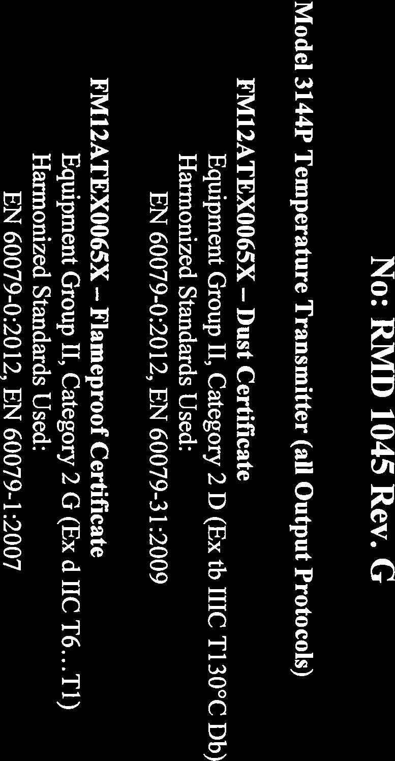
13 Europe E1 I1 N1 ND Quick Start Guide ATEX Flameproof Certificate: FM12ATEX0065X Standards: EN : 2012, EN : 2007, EN 60529:1991 +A1:2000 Markings: II 2 G Ex d IIC T6 T1 Gb, T6(-50 C T a +40 C), T5 T1(-50 C T a +60 C); See Table 3 at the end of the Product Certifications section for Process Temperatures. Special Conditions for Safe Use (X): 1. See certificate for ambient temperature range. 2. The non-metallic label may store an electrostatic charge and become a source of ignition in Group III environments. 3. Guard the LCD display cover against impact energies greater than 4 joules. 4. Consult the manufacturer if dimensional information on the flameproof joints is necessary. ATEX Intrinsic Safety Certificate: Baseefa03ATEX0708X Standards: EN : 2012; EN :2012; Markings: II 1 G Ex ia IIC T4 Ga; T4(-60 C T a +60 C), See Table 4 at the end of the Product Certifications section for Entity Parameters. Special Conditions for Safe Use (X): 1. When fitted with the transient terminal options, the equipment is not capable of passing the 500 V insulation test. This must be taken into account during installation. 2. The enclosure may be made from aluminum alloy with a protective polyurethane paint finish; however, care should be taken to protect it from impact or abrasion when located in Zone 0. ATEX Type n Certificate: aseefa03atex0709x Standards: EN :2012, EN :2010 Markings: II 3 G Ex na IIC T5 Gc; T5(-40 C T a +75 C); Special Condition for Safe Use (X): 1. When fitted with the transient terminal options, the equipment is not capable of withstanding the 500 V electrical strength test as defined in clause of EN : This must be taken into account during installation. ATEX Dust Certificate: FM12ATEX0065X Standards: EN : 2012, EN : 2009, EN 60529:1991 +A1:2000 Markings: II 2 D Ex tb IIIC T130 C Db, (-40 C T a +70 C); IP66 See Table 3 at the end of the Product Certifications section for Process Temperatures. Special Conditions for Safe Use (X): 1. See certificate for ambient temperature range. 2. The non-metallic label may store an electrostatic charge and become a source of ignition in Group III environments. 3. Guard the LCD display cover against impact energies greater than 4 joules. 4. Consult the manufacturer if dimensional information on the flameproof joints is necessary. 13
14 Quick Start Guide International E7 I7 N7 IECEx Flameproof Certificate: IECEx FMG X Standards: IEC :2011, IEC : , IEC :2008 Markings: Ex d IIC T6 T1 Gb, T6(-50 C T a +40 C), T5 T1(-50 C T a +60 C); Ex tb IIIC T130 C Db, (-40 C T a +70 C); IP66; See Table 3 at the end of the Product Certifications section for Process Temperatures. Special Conditions for Safe Use (X): 1. See certificate for ambient temperature range. 2. The non-metallic label may store an electrostatic charge and become a source of ignition in Group III environments. 3. Guard the LCD display cover against impact energies greater than 4 joules. 4. Consult the manufacturer if dimensional information on the flameproof joints is necessary. IECEx Intrinsic Safety Certificate: IECEx BAS X Standards: IEC : 2011; IEC : 2011; Markings: Ex ia IIC T4 Ga; T4(-60 C T a +60 C), See Table 4 at the end of the Product Certifications section for Entity Parameters. Special Conditions for Safe Use (X): 1. When fitted with the transient terminal options, the apparatus is not capable of withstanding the 500 V electrical strength test as defined in Clause of IEC : This must be taken into account during installation. 2. The enclosure may be made from aluminum alloy with a protective polyurethane paint finish; however, care should be taken to protect it from impact or abrasion when located in Zone 0. IECEx Type n Certificate: IECEx BAS X Standards: IEC :2011, IEC :2010 Markings: Ex na IIC T5 Gc; T5(-40 C T a + 75 C), Brazil E2 INMETRO Flameproof Certificate: UL-BR X Standards: ABNT NBR IEC : corrigendum 1:2011, ABNT NBR IEC : corrigendum 1:2011 Markings: Ex d IIC T6...T1* Gb; T6 T1*: -50 C T a +40 C, T5...T1*: - 50 C T a +60 C) Special Conditions for Safe Use (X): 1. See product description for ambient temperature limits and process temperature limits. 2. The non-metallic label may store an electrostatic charge and become a source of ignition in Group III environments. 3. Guard the LCD cover against impact energies greater than 4 joules. 4. Consult the manufacturer if dimensional information on the flameproof joints is necessary. 14
15 Quick Start Guide I2 INMETRO Intrinsic Safety Certificate: UL-BR X Standards: ABNT NBR IEC : corrigendum 1:2011, ABNT NBR IEC :2009 Markings: Ex ia IIC T4 Ga (-60 C T a +60 C), See Table 4 at the end of the Product Certifications section for Entity Parameters. Special Condition for Safe Use (X): 1. When mounted with the terminal options with transient protection, the equipment is not capable of withstanding the dielectric strength test with 500 V as defined in ISO IEC This feature should be taken into account during installation. China E3 China Flameproof Certificate: GYJ X Standards: GB , GB Markings: Ex d IIC T5/T6 Gb Special Conditions for Safe Use (X): 1. Symbol X is used to denote specific conditions of use: For information on the dimensions of the flameproof joints the manufacturer shall be contacted. This shall be mentioned in the manual. 2. Relation between T code and ambient temperature range is: T code Ambient temperature T6-40 C T a +70 C T5-40 C T a +80 C 3. The earth connection facility in the enclosure should be connected reliably. 4. During installation, there should be no mixture harmful to flameproof housing. 5. During installation in hazardous location. Cable glands, conduits and blanking plugs, certified by state-appointed inspection bodies with Ex d IIC Gb degree, should be used. 6. During installation, use and maintenance in explosive gas atmospheres, observe the warning Do not open when energized. 7. End users is not permitted to change any components insides, but to settle the problem in conjunction with manufacturer to avoid damage to the product. 8. When installation, use and maintenance of this product, observe following standards: GB Electrical apparatus for explosive gas atmospheres Part 13: Repair and overhaul for apparatus used in explosive gas atmospheres GB Electrical apparatus for explosive gas atmospheres Part 15: Electrical installations in hazardous area (other than mines) GB Electrical apparatus for explosive gas atmospheres Part 16: Inspection and maintenance of electrical installation (other than mines) GB Code for construction and acceptance of electric device for explosion atmospheres and fire hazard electrical equipment installation engineering 15
16 Quick Start Guide I3 China Intrinsic Safety Certificate: GYJ X Standards: GB , GB Markings: Ex ia IIC T4/T5/T6 Special Conditions for Safe Use (X): 1. Symbol X is used to denote specific conditions of use: a. The enclosure may contain light metal, attention should be taken to avoid ignition hazard due to impact or friction when used in Zone 0. b. When fitted with the Transient Terminal Option, this apparatus is not capable of withstanding the 500 V r.m.s. insulation test required by Clause of GB Relation between T code and ambient temperature range is: T code 3. Parameters: Power/loop terminals (+ and -) Sensor terminal (1 to 5) Ambient temperature T4-60 C T a +60 C Maximum input voltage: Maximum input current: Load connected to sensor terminals (1 to 5) Maximum input power: Maximum internal parameters U i (V) l i (ma) P i (W) C i (nf) L i (μh) Maximum input voltage: Group Maximum input current: Maximum input power: Maximum internal parameters U o (V) l o (ma) P o (W) C i (nf) L i (μh) Maximum external parameters C o (μf) L o (μh) IIC IIB IIA Temperature transmitters comply to the requirements for FISCO field devices specified in GB FISCO parameters are as follows: Maximum input voltage: Maximum input current: Maximum input power: Maximum internal parameters U i (V) l i (ma) P i (W) C i (nf) L i (μh) The product should be used with Ex-certified associated apparatus to establish explosion protection system that can be used in explosive gas atmospheres. Wiring and terminals should comply with the instruction manual of the product and associated apparatus. 16
17 Quick Start Guide 5. The cables between this product and associated apparatus should be shielded cables (the cables must have insulated shield). The shielded has to be grounded reliably in non-hazardous area. 6. End users are not permitted to change any components insides, but to settle the problem in conjunction with manufacturer to avoid damage to the product. 7. When installation, use and maintenance of this product, observe following standards: GB Electrical apparatus for explosive gas atmospheres Part 13: Repair and overhaul for apparatus used in explosive gas atmospheres GB Electrical apparatus for explosive gas atmospheres Part 15: Electrical installations in hazardous area (other than mines) GB Electrical apparatus for explosive gas atmospheres Part 16: Inspection and maintenance of electrical installation (other than mines) GB Code for construction and acceptance of electric device for explosion atmospheres and fire hazard electrical equipment installation engineering EAC - Belarus, Kazakhstan, Russia EM IM Technical Regulation Customs Union (EAC) Flameproof Certificate: RU C-US.GB05.B Markings: 1Ex d IIC T6 T1 Gb X Special Condition for Safe Use (X): 1. See certificate for special conditions. Technical Regulation Customs Union (EAC) Intrinsic Safety Certificate: RU C-US.GB05.B Markings: 0Ex ia IIC T4 Ga X Special Condition for Safe Use (X): 1. See certificate for special conditions. Japan E4 TIIS Flameproof Certificate: TC16120, TC16121 Markings: Ex d IIB T6 (-20 C T a +55 C) Certificate: TC16127, TC16128, TC16129, TC16130 Markings: Ex d IIB T4 (-20 C T a +55 C) Combinations K1 Combination of E1, I1, N1, and ND K2 Combination of E2 and I2 K5 Combination of E5 and I5 K7 Combination of E7, I7, N7 KA Combination of K1 and K6 KB Combination of K5, I6, and K6 KM Combination of EM and IM 17
18 Quick Start Guide Tables Table 3. Process Temperatures T6 T5 T4 T3 T2 T1 T130 Max ambient + 40 C + 60 C + 60 C + 60 C + 60 C + 60 C + 70 C Transmitter with LCD display 0-in. 55 C 70 C 95 C 95 C 95 C 95 C 95 C 3-in. 55 C 70 C 100 C 100 C 100 C 100 C 100 C Sensor extension 6-in. 60 C 70 C 100 C 100 C 100 C 100 C 100 C 9-in. 65 C 75 C 110 C 110 C 110 C 110 C 110 C Transmitter without LCD display 0-in. 55 C 70 C 100 C 170 C 280 C 440 C 100 C 3-in. 55 C 70 C 110 C 190 C 300 C 450 C 110 C 6-in. 60 C 70 C 120 C 200 C 300 C 450 C 110 C 9-in. 65 C 75 C 130 C 200 C 300 C 450 C 120 C Table 4. Entity Parameters HART Fieldbus/PROFIBUS FISCO Voltage U i (V) Current I i (ma) Power P i (W) Capacitance C i (nf) Inductance L i (mh)


19 Quick Start Guide Figure 5. Rosemount 3144P Declaration of Conformity 19


20 Quick Start Guide 20


21 Quick Start Guide 21
22 * * Quick Start Guide , Rev CB Global Headquarters Emerson Process Management 6021 Innovation Blvd Shakopee, MN 55379, USA or North America Regional Office Emerson Process Management 8200 Market Blvd. Chanhassen, MN 55317, USA or Latin America Regional Office Emerson Process Management 1300 Concord Terrace, Suite 400 Sunrise, Florida, 33323, USA Europe Regional Office Emerson Process Management Europe GmbH Neuhofstrasse 19a P.O. Box 1046 CH 6340 Baar Switzerland +41 (0) (0) Asia Pacific Regional Office Emerson Process Management Asia Pacific Pte Ltd 1 Pandan Crescent Singapore Enquiries@AP.EmersonProcess.com Middle East and Africa Regional Office Emerson Process Management Emerson FZE P.O. Box 17033, Jebel Ali Free Zone - South 2 Dubai, United Arab Emirates RFQ.RMTMEA@Emerson.com Standard Terms and Conditions of Sale can be found at: The Emerson logo is a trademark and service mark of Emerson Electric Co. Rosemount and Rosemount logotype are registered trademarks of Rosemount Inc. HART is a registered trademark of FieldComm Group. FOUNDATION fieldbus is a trademark of FieldComm Group. PROFIBUS is a registered trademark of PROFINET International (PI). All other marks are the property of their respective owners Rosemount Inc. All rights reserved.
Rosemount 3144P Temperature Transmitters with FOUNDATION Fieldbus Protocol. Quick Start Guide , Rev DA June 2016
 Rosemount 3144P Temperature Transmitters with FOUNDATION Fieldbus Protocol 00825-0100-4834, Rev DA NOTICE This guide provides basic guidelines for Rosemount 3144P. It does not provide instructions for
Rosemount 148 Temperature Transmitter. Quick Start Guide , Rev GA September 2016
 Rosemount 148 Temperature Transmitter 00825-0100-4148, Rev GA NOTICE This guide provides basic guidelines for the Rosemount 148. It does not provide instructions for detailed configuration, diagnostics,
Rosemount 0085 Pipe Clamp Sensor Assembly. Quick Start Guide , Rev CA June 2016
 Rosemount 0085 Pipe Clamp Sensor Assembly 00825-0100-4952, Rev CA NOTICE This guide provides basic guidelines for Rosemount 0085 Pipe Clamp Sensor. It does not provide instructions for configuration, diagnostics,
Rosemount 752 FOUNDATION Fieldbus Remote Indicator
 Rosemount 752 FOUNDATION Fieldbus Remote Indicator Product Data Sheet 00813-0100-4377, Rev FA Two-wire segment powered device Displays up to eight values Link Master Capability Optional PID, Characterizer,
Rosemount 644H Temperature Transmitters
 Quick Start Guide 00825-0100-4829, Rev DA Rosemount 644H Temperature Transmitters with FOUNDATION Fieldbus Quick Start Guide NOTICE This guide provides basic guidelines for the Rosemount 644. It does not
SmartPower Solutions. Quick Start Guide , Rev CA March 2015
 SmartPower Solutions 00825-0100-4701, Rev CA NOTICE This guide provides basic guidelines for the SmartPower family of products. It does not provide instructions for detailed configuration, diagnostics,
Rosemount 644H Temperature Transmitters
 Quick Start Guide 00825-0300-4728, Rev BA Rosemount 644H Temperature Transmitters with PROFIBUS PA Quick Start Guide NOTICE This guide provides basic guidelines for the Rosemount 644. It does not provide
Quick Start Guide , Rev EA December Rosemount 0065/0185 Sensor Assembly
 Quick Start Guide 00825-0200-2654, Rev EA Rosemount 0065/0185 Sensor Assembly Quick Start Guide NOTICE This guide provides basic guidelines for Rosemount 0065 and 0185 Sensor models. It does not provide
Rosemount 214C Sensor. Quick Start Guide , Rev AF August 2017
 Rosemount 214C Sensor 00825-0400-2654, Rev AF NOTICE This guide provides basic guidelines for Rosemount 214C Sensor models. If the sensor was ordered assembled to a temperature thermowell or transmitter,
Rosemount 3144P Temperature Transmitter
 00825-0100-4021, Rev MA Rosemount 3144P Temperature Transmitter with HART Protocol and Rosemount X-well Technology NOTICE This guide provides basic guidelines for the Rosemount 3144P Transmitter. It does
Rosemount 848T FOUNDATION Fieldbus High Density Temperature Transmitter
 Quick Start Guide 00825-0100-4697, Rev SF Rosemount 848T FOUNDATION Fieldbus High Density Temperature Transmitter Device Revision 8 - Requires New DD/CFF Revision Quick Start Guide NOTICE This guide provides
Rosemount 752 Remote Indicator
 Quick Start Guide 00825-0100-4377, Rev EA Rosemount 752 Remote Indicator with FOUNDATION Fieldbus Protocol Quick Start Guide This guide provides basic guidelines for Rosemount 752 Remote Indicator. It
Rosemount 0085 Pipe Clamp Sensor Assembly. Quick Start Guide , Rev DC August 2017
 Rosemount 0085 Pipe Clamp Sensor Assembly Quick Start Guide 00825-0100-4952, Rev DC Quick Start Guide NOTICE This guide provides basic guidelines for Rosemount 0085 Pipe Clamp Sensor. It does not provide
Rosemount 2090F Hygienic Pressure Transmitter
 Rosemount 2090F Hygienic Pressure Transmitter Product Data Sheet November 2016 00813-0100-4698, Rev FC Conforms to 3-A Sanitary Standards Features CIP/SIP service for process temperatures up to 284 F (140
Quick Start Guide , Rev DA December Rosemount Volume 1 Sensor Assembly
 Quick Start Guide 00825-0300-2654, Rev DA Rosemount Volume 1 Sensor Assembly Quick Start Guide NOTICE This guide provides basic guidelines for Rosemount 0068, 0078, and 0183 Sensor models. It does not
Rosemount 3144P Temperature Transmitter
 Quick Start Guide 00825-0100-4021, Rev NA Rosemount 3144P Temperature Transmitter with HART Protocol and Rosemount X-well Technology Quick Start Guide NOTICE This guide provides basic guidelines for the
Annubar Flowmeter Series
 Reference Manual Appendix B Approvals Annubar Flowmeter Series Hazardous Locations Installations.................. page B-1 Rosemount 3051SFA Product Certifications.......... page B-1 Rosemount 3095MFA
Rosemount 644H Temperature Transmitters
 Quick Start Guide 00825-0300-4728, Rev CA Rosemount 644H Temperature Transmitters with PROFIBUS PA Quick Start Guide NOTICE This guide provides basic guidelines for the Rosemount 644. It does not provide
Rosemount Pipe Clamp Sensor. Reference Manual , Rev BA February 2014
 Rosemount Pipe Clamp Sensor Reference Manual Reference Manual Title Page The Rosemount 0085 Pipe Clamp Sensor NOTICE Read this manual before working with the product. For personal and system safety, and
Rosemount 2090F Hygienic Pressure Transmitter
 Rosemount 2090F Hygienic Pressure Transmitter Product Data Sheet December 2017 00813-0100-4698, Rev GA Conforms to 3-A Sanitary Standards Features CIP/SIP service for process temperatures up to 284 F (140
Rosemount 3490 Series 4 20 ma + HART Compatible Controller
 00825-0200-4841, Rev AB Rosemount 3490 Series 4 20 ma + HART Compatible Controller Failure to follow safe installation guidelines could result in death or serious injury The Rosemount 3490 Series Control
Rosemount 4600 Oil & Gas Panel Pressure Transmitter
 Product Data Sheet October 2017 00813-0100-4022, Rev LA Rosemount 4600 Oil & Gas Panel Pressure Transmitter A compact, lightweight, all-welded stainless steel design Up to 40:1 rangeability for increased
Rosemount 644 Temperature Transmitter
 Quick Start Guide 00825-0200-4728, Rev GB Rosemount 644 Temperature Transmitter with 4 20 ma HART Protocol (Revision 5 and 7) Note Before installing the transmitter, confirm the correct device driver is
Rosemount 4600 Oil & Gas Panel Pressure Transmitter. Quick Start Guide , Rev GA September 2017
 Rosemount 4600 Oil & Gas Panel Pressure Transmitter 00825-0100-4022, Rev GA NOTICE NOTICE This guide provides basic guidelines for the Rosemount 4600 Oil & Gas Panel Pressure Transmitter. It does not provide
Quick Start Guide , Rev DA June Rosemount 644H (Device Revision 7 or Previous) and 644R Smart Temperature Transmitters
 and 644R Smart Temperature Transmitters") Quick Start Guide 00825-0100-4728, Rev DA Rosemount 644H (Device Revision 7 or Previous) and 644R Smart Temperature Transmitters Quick Start Guide NOTICE This guide provides basic guidelines for the Rosemount
Quick Start Guide 00825-0100-4728, Rev DA Rosemount 644H (Device Revision 7 or Previous) and 644R Smart Temperature Transmitters Quick Start Guide NOTICE This guide provides basic guidelines for the Rosemount
Rosemount 248 Temperature Transmitter
 Product Data Sheet November 2013 00813-0100-4825, Rev KA Rosemount 248 Temperature Transmitter Basic temperature transmitter offers a reliable solution for temperature monitoring points transmitter design
Rosemount 2051 Pressure Transmitter and Rosemount 2051CF Series Flowmeter
 Quick Start Guide 00825-0400-4101, Rev AD Rosemount 2051 Pressure Transmitter and Rosemount 2051CF Series Flowmeter with PROFIBUS PA Protocol Quick Start Guide NOTICE This installation guide provides basic
Rosemount 248 Temperature Transmitter. Quick Start Guide , Rev. EA April 2013
 Rosemount 248 Temperature Transmitter 00825-0100-4825, Rev. EA NOTICE This installation guide provides basic guidelines for the Rosemount 248 Wireless. It does not provide instructions for detailed configuration,
Rosemount 3051 Pressure Transmitter and Rosemount 3051CF Series Flowmeter
 Quick Start Guide 00825-0100-4797, Rev ED Rosemount 3051 Pressure Transmitter and Rosemount 3051CF Series Flowmeter with PROFIBUS PA Protocol Quick Start Guide NOTICE This installation guide provides basic
Rosemount 2088, 2090F, and 2090P Pressure Transmitter
 Quick Start Guide 00825-0100-4108, Rev BA Rosemount 2088, 2090F, and 2090P Pressure Transmitter with 4-20 ma HART and 1-5 Vdc Low Power HART Protocol (Revision 5 and 7) Quick Start Guide NOTICE This guide
Rosemount 2051G Pressure Transmitter
 Quick Start Guide 00825-0700-4101, Rev AB Rosemount 2051G Pressure Transmitter with 4 20 ma HART Protocol (Revision 5 and 7) Quick Start Guide NOTICE This guide provides basic guidelines for Rosemount
Rosemount 3051S MultiVariable Transmitter Rosemount 3051SF Series MultiVariable Flowmeter
 Quick Start Guide 00825-0100-4853, Rev AD Rosemount 3051S MultiVariable Transmitter Rosemount 3051SF Series MultiVariable Flowmeter with FOUNDATION Fieldbus Protocol Quick Start Guide NOTICE This guide
Quick Start Guide , Rev HA January Rosemount 248 Temperature Transmitter
 00825-0100-4825, Rev HA Rosemount 248 Temperature Transmitter NOTICE This guide provides basic guidelines for the Rosemount 248. It does not provide instructions for detailed configuration, diagnostics,
Rosemount 752 Fieldbus Remote Indicator
 Product Data Sheet Rosemount 752 Rosemount 752 Fieldbus Remote Indicator ROSEMOUNT 752 DELIVERS: Two-wire segment powered device Displays up to 8 values Link Master Capability Optional PID, Characterizer,
Rosemount 248 Temperature Transmitter
 Product Data Sheet March 2017 00813-0100-4825, Rev LA Rosemount 248 Temperature Transmitter Basic temperature transmitter offers a reliable solution for temperature monitoring points. Standard transmitter
SmartPower Solutions. SmartPower Solutions. Product Data Sheet , Rev AC January Contents
 Product Data Sheet Intrinsically Safe design enables ability to perform routine maintenance in hazardous areas Predictable life specified under installed conditions Robust design for use in harsh environments
Model 144H. Product Data Sheet , Rev DB February Content
 Rosemount 144 PC-Programmable Temperature Transmitter Provides an installation-ready solution for temperature monitoring applications using Complete Point Solutions (CPS) Increases measurement accuracy
Rosemount 2088, 2090P, and 2090F Pressure Transmitters
 Quick Start Guide 00825-0100-4690, Rev FD Rosemount 2088, 2090P, and 2090F Pressure Transmitters with 4 20 ma HART and 1 5 Vdc HART Low Power Protocol Quick Start Guide NOTICE This installation guide provides
Emerson Wireless SmartPower Solutions
 Product Data Sheet 00813-0100-4701 Rev CA Emerson Wireless SmartPower Solutions Intrinsically Safe design enables routine maintenance in hazardous areas Predictable life specified under installed conditions
SmartPower Solutions [ SmartPower Solutions. Quick Installation Guide , Rev AC January 2012
 Start Step 1: Physical Installation Step 2: Verify Operation Disposal/Recycling of Depleted Power Modules Product Certifications EC Declaration of Conformity End 00825-0100-4701[ 2012 Rosemount Inc. All
Rosemount 705 Wireless Totalizing Transmitter
 Quick Start Guide 00825-0200-4705, Rev CB Rosemount 705 Wireless Totalizing Transmitter An installation-ready solution that provides simple connection to a turbine meter. Measures average flow and totalized
Rosemount 3144P Temperature Transmitter with HART Protocol
 Quick Installation Guide Rosemount 3144P Rosemount 3144P Temperature Transmitter with HART Protocol Start Step 1: Configure (Bench Calibration) Step 2: Verify Configuration Step 3: Set the Switches Step
Rosemount 3051HT Hygienic Pressure Transmitter
 00825-0100-4091, Rev CA Rosemount 3051HT Hygienic Pressure Transmitter with 4 20 ma HART Revision 5 and 7 Protocol Note Before installing the transmitter, confirm the correct device driver is loaded on
Rosemount 248 Temperature Transmitter
 Product Data Sheet January 2018 00813-0100-4825, Rev LB Rosemount 248 Temperature Transmitter Basic temperature transmitter offers a reliable solution for temperature monitoring points. Standard transmitter
Rosemount 3051 Pressure Transmitter
 Quick Start Guide 00825-0100-4001, rev. JA Rosemount 3051 Pressure Transmitter with 4-20 ma HART and 1-5 Vdc Low Power Protocol Rosemount 3051CF Series Flowmeter Transmitter with 4-20 ma HART and 1-5 Vdc
Rosemount 3144P Temperature Transmitter
 Product Data Sheet August 2014 00813-0100-4021, Rev NA Rosemount 3144P Temperature Transmitter For every responsibility you have, you are confronted with a number of challenges. You have aggressive production
Rosemount 848T High Density Temperature Measurement Family
 Product Data Sheet July 2017 00813-0100-4697, Rev PA Rosemount 848T High Density Temperature Measurement Family Innovative temperature measurement for high density applications that provide installation
Rosemount 3051S MultiVariable Extension Supplement
 Product Data Sheet April 2015 00813-0400-4801, Rev AA Rosemount 3051S MultiVariable Extension Supplement With the Rosemount 3051S MultiVariable Extensions, you can gain valuable process insight with two
Rosemount 2088 Absolute and Gage Pressure Transmitter
 Product Data Sheet February 2015 00813-0100-4690, Rev PB Rosemount 2088 Absolute and Gage Pressure Transmitter Performance of 0.065% with High Accuracy option Lightweight, compact design for cost-effective
Rosemount 2051 Pressure Transmitter with 4-20 ma HART and 1-5 Vdc HART Low Power Protocol
 Quick Installation Guide August 2009 Rosemount 2051 Rosemount 2051 Pressure Transmitter with 4-20 ma HART and 1-5 Vdc HART Low Power Protocol Start Step 1: Mount the Transmitter Step 2: Consider Housing
Rosemount 2088, 2090F, and 2090P Pressure Transmitter
 Quick Start Guide 00825-0100-4108, Rev CA Rosemount 2088, 2090F, and 2090P Pressure Transmitter with 4 20 ma HART and 1 5 Vdc Low Power HART Protocol (Revision 5 and 7) Quick Start Guide NOTICE This guide
Rosemount 3051S MultiVariable Transmitter Rosemount 3051SF Series Flowmeter MultiVariable Transmitter
 Quick Start Guide 00825-0100-4803, Rev EA Rosemount 3051S MultiVariable Transmitter Rosemount 3051SF Series Flowmeter MultiVariable Transmitter Quick Start Guide NOTICE This guide provides basic guidelines
Rosemount 3051S Series Pressure Transmitter and Rosemount 3051SF Series Flowmeter
 Quick Start Guide 00825-0100-4801, Rev MC Rosemount 3051S Series Pressure Transmitter and Rosemount 3051SF Series Flowmeter with HART Protocol Quick Start Guide NOTICE This guide provides basic guidelines
Rosemount 702 Wireless Discrete Transmitter
 August 2009 Rosemount 702 Rosemount 702 Wireless Discrete Transmitter Start Step 1: Physical Installation Step 2: Verify Operation Step 3: Reference Information Product Certifications EC Declaration of
Rosemount 3144P Rosemount 3144P Temperature Transmitter
 Temperature Transmitter Sensor Drift Alert and Hot Backup features improve measurement reliability while the Transmitter-Sensor Matching feature improves temperature measurement accuracy Statistical Process
Rosemount 2090P Pulp and Paper Pressure Transmitter
 Product Data Sheet Rosemount 2090P Pulp and Paper Pressure Transmitter Rosemount 2090P 1-inch flush mount compatible with a PMC process connection, or 1 1 /2-inch threaded mounting connection Absolute
Rosemount 8800D Series Vortex Flowmeter
 Quick Installation Guide Rosemount 8800D Rosemount 8800D Series Vortex Flowmeter Start Step 1: Mount the Flowmeter Step 2: Consider Housing Rotation Step 3: Set Jumpers and Switches Step 4: Connect Wiring
Rosemount 3490 Series
 Product Data Sheet July 2014 00813-0100-4841, Rev DA Rosemount 3490 Series 4 20 ma + HART Compatible Controller Field mounted controller with integral multi-function LCD and keypad Tough weatherproof wall
Rosemount 3051S MultiVariable Transmitter Rosemount 3051SF Series Flowmeter MultiVariable Transmitter
 00825-0100-4803, Rev EE Rosemount 3051S MultiVariable Transmitter Rosemount 3051SF Series Flowmeter MultiVariable Transmitter NOTICE This guide provides basic guidelines for the Rosemount 3051S MultiVariable
Rosemount 2088, 2090P, and 2090F Pressure Transmitters
 April 2013 Rosemount 2088 and 2090 Rosemount 2088, 2090P, and 2090F Pressure Transmitters with 4-20 ma HART and 1-5 Vdc HART Low Power Protocol Start Step 1: Mount the Transmitter Step 2: Set the Jumpers
Rosemount 4088B MultiVariable Transmitter with Bristol Standard Asynchronous/Synchronous Protocol (BSAP)/MVS Protocol
/MVS Protocol") Quick Start Guide 00825-0200-4088, Rev CA Rosemount 4088B MultiVariable Transmitter with Bristol Standard Asynchronous/Synchronous Protocol (BSAP)/MVS Protocol Quick Start Guide NOTICE This installation
Quick Start Guide 00825-0200-4088, Rev CA Rosemount 4088B MultiVariable Transmitter with Bristol Standard Asynchronous/Synchronous Protocol (BSAP)/MVS Protocol Quick Start Guide NOTICE This installation
Rosemount 3051S MultiVariable Transmitter Rosemount 3051SF Series Flowmeter MultiVariable Transmitter
 Quick Start Guide 00825-0100-4803, Rev EF Rosemount 3051S MultiVariable Transmitter Rosemount 3051SF Series Flowmeter MultiVariable Transmitter Quick Start Guide NOTICE This guide provides basic guidelines
Rosemount 3051P In-Line Pressure Transmitter. Product Data Sheet August , Rev BA
 Rosemount 3051P In-Line Pressure Transmitter Product Data Sheet August 2018 00813-0100-4680, Rev BA August 2018 Settings the standard for pressure measurement Proven best-in-class performance and safety
Model 144H. Product Data Sheet , Rev DB February Content
 Rosemount 144 PC-Programmable Temperature Transmitter Provides an installation-ready solution for temperature monitoring applications using Complete Point Solutions (CPS) Increases measurement accuracy
Rosemount 4500 Hygienic Pressure Transmitter. Start
 Quick Installation Guide June 2007 Rosemount 4500 Rosemount 4500 Hygienic Pressure Transmitter ProductDiscontinued Start Step 1: Mount the Transmitter Step 2: Set the Switches Step 3: Connect Wiring and
Rosemount 3100 Series Ultrasonic Level Transmitters
 Product Data Sheet Ultrasonic Level Transmitters Non-contacting measurement with no moving parts Integral LCD and push-buttons as standard for on-site programming Continuous measurement of level or distance-to-surface.
Rosemount 8800D Series Vortex Flowmeter. Quick Start Guide , Rev FE October 2018
 Rosemount 8800D Series Vortex Flowmeter 00825-0100-4004, Rev FE 1 About this guide This guide provides basic guidelines for the Rosemount 8800D Series Vortex Flowmeter. It does not provide instructions
Rosemount 3051S Series Pressure Transmitter and Rosemount 3051SF Series Flowmeter
 Quick Start Guide 00825-0100-4801, Rev NA Rosemount 3051S Series Pressure Transmitter and Rosemount 3051SF Series Flowmeter with HART Protocol Quick Start Guide NOTICE This guide provides basic guidelines
Rosemount 3100 Series Ultrasonic Level Transmitters
 Product Data Sheet Ultrasonic Level Transmitters Non-contacting measurement with no moving parts Integral LCD and push-buttons as standard for on-site programming Continuous measurement of level or distance-to-surface.
Rosemount 644H and 644R Smart Temperature Transmitters
 Quick Installation Guide March 2011 Rosemount 644 Rosemount 644H and 644R Smart Temperature Transmitters Start Step 1: Configure (Bench Calibration) Step 2: Verify Configuration Step 3: Set the Switches
User s Manual YTA610 and YTA710 NEPSI Certification
 User s Manual YTA60 and YTA70 NEPSI Certification [Option code: /NS, /NS5 and /NF] st Edition . INTRODUCTION Thank you for purchasing the YTA60 and YTA70 Temperature transmitters. This manual contains
Rosemount 2088 Absolute and Gage Pressure Transmitter
 Product Data Sheet Rosemount 2088 Rosemount 2088 Absolute and Gage Pressure Transmitter Performance of 0.075% with High Accuracy option Lightweight, compact design for cost effective installation Protocols
Rosemount 3144P Temperature Transmitter
 Temperature Transmitter Sensor Drift Alert and Hot Backup features improve measurement reliability while the Transmitter-Sensor Matching feature improves temperature measurement accuracy Statistical Process
Rosemount 4500 Hygienic Pressure Transmitter Demonstrated best-in-class performance during SIP/CIP for process temperatures up to 400 F (204 C)
") Product Data Sheet December 2012 00813-0100-4027, Rev BB Rosemount 4500 Hygienic Pressure Transmitter ProductDiscontinued R 37-01 Hygienic design conforms to 3-A and EHEDG standards Demonstrated best-in-class
Product Data Sheet December 2012 00813-0100-4027, Rev BB Rosemount 4500 Hygienic Pressure Transmitter ProductDiscontinued R 37-01 Hygienic design conforms to 3-A and EHEDG standards Demonstrated best-in-class
Rosemount 4500 Hygienic Pressure Transmitter
 Product Data Sheet Rosemount 4500 Rosemount 4500 Hygienic Pressure Transmitter Hygienic design conforms to 3-A and EHEDG standards Demonstrated best-in-class performance during SIP/CIP for process temperatures
J. Rosemount 3051S Series Pressure Transmitter and Rosemount 3051SF Series Flowmeter with HART Protocol.
 Quick Installation Guide Rosemount 3051S Series Pressure Transmitter and Rosemount 3051SF Series Flowmeter with HART Protocol Rosemount 3051S Start Step 1: Mount the Transmitter Step 2: Consider Housing
Rosemount 3051 Pressure Transmitter Includes Transmitter Option TR ProductDiscontinued. Start
 Quick Installation Guide June 2009 Rosemount 3051 Rosemount 3051 Pressure Transmitter Includes Transmitter Option TR ProductDiscontinued Start Step 1: Mount the Transmitter Step 2: Consider Housing Rotation
Rosemount 2090F Hygienic Pressure Transmitter
 Hygienic Pressure Transmitter Conforms to 3-A Sanitary s Features CIP/SIP service for process temperatures up to 284 F (140 C) Absolute or gage pressure ranges from 0-1.5 to 0-300 psi Mounts with either
Rosemount 3095MFC Compact Orifice Mass Flowmeter
 Rosemount 3095MFC Compact Orifice Mass Flowmeter SPECIFICATIONS Performance System Reference Accuracy Percent (%) of mass flow rate TABLE 11. 3095MFC Compact Orifice Mass Flowmeter TYPE Repeatability ±0.1%
Rosemount 3144P Temperature Transmitter
 Temperature Transmitter Sensor Drift Alert and Hot Backup features improve measurement reliability while the Transmitter-Sensor Matching feature improves temperature measurement accuracy. Communicates
Rosemount 8600 Series Vortex Flowmeter. Quick Start Guide , Rev EB April 2018
 Rosemount 8600 Series Vortex Flowmeter 00825-0100-4860, Rev EB April 2018 April 2018 1 About this guide This guide provides basic guidelines for the Rosemount 8600D Series Vortex Flowmeter. It does not
Rosemount 3144P Rosemount 3144P Temperature Transmitter
 Product Data Sheet Rosemount 3144P Rosemount 3144P Temperature Transmitter Industry-leading temperature transmitter delivers unmatched field reliability and innovative process measurement solutions Achieve
SmartLine. RMA803 SmartLine Remote Fieldbus Indicator Specification 34-ST-03-90, December Technical Information.
 SmartLine Technical Information RMA803 SmartLine Remote Fieldbus Indicator Specification 34-ST-03-90, December 2015 Introduction The Honeywell RMA803 is a Foundation Fieldbus remote indicator suitable
Rosemount High Density Temperature Measurement. Simplify Your Project
 Rosemount High Density Temperature Measurement Simplify Your Project 848 Balancing Project Risk is a Daunting Challenge Emerson s approach to temperature measurement can help lower the risk of budget overruns
Rosemount 3051CFP Integral Orifice Flowmeter
 December 2013 Rosemount 3051 Rosemount 3051CFP Integral Orifice Flowmeter See Specifications on page 47 and options for more details on each configuration. Rosemount 3051CFP Integral Orifice Flowmeters
Dräger Polytron 8100 EC Detection of toxic gases and oxygen
 Dräger Polytron 8100 EC Detection of toxic gases and oxygen The Polytron 8100 EC is Dräger s top of the line explosion-proof transmitter for the detection of toxic gases or oxygen It uses a high performance
Rosemount 3051CFC Compact Flowmeter
 CFC Compact Flowmeter CFC Compact Flowmeters provide a quick, reliable installation between existing raised face flanges. Depending on your application needs, you can reduce energy loss with the Compact
Rosemount 2140 and 2140:SIS Level Detectors
 Product Data Sheet 00813-0100-4140, Rev BB Rosemount 2140 and 2140:SIS Level Detectors Vibrating ork Integrates into existing wired HART loops of automated systems without extra wiring costs Switch between
Rosemount 2100 Series
 Rosemount 2100 Series Vibrating Fork Liquid Level Switches Level switches for demanding applications Reliable performance... Rosemount 2100 series vibrating fork level switches are suitable for virtually
Dräger Polytron 8100 EC Detection of toxic gases and vapors
 Dräger Polytron 8100 EC Detection of toxic gases and vapors The Polytron 8100 EC is Dräger s top of the line explosion proof transmitter for the detection of toxic gases or oxygen It uses a high performance
Certificate of Compliance
 FF0 001 Certificate of Compliance Certificate: 70116279 (LR 025993_0_000) Issued to: General Monitors, Incorporated 26776 Simpatica Circle Lake Forest, California 92630 USA Attention: Larry Vlagea The
UL HAZARDOUS LOCATIONS SERVICES
 UL HAZARDOUS LOCATIONS SERVICES The international preference in hazardous locations certification for over 100 years ul.com/hazloc Explosive Gas Atmospheres Class I Division S Includes flammable gases,
Certificate of Compliance
 FF0 001 Certificate of Compliance Certificate: 70116284 (LR 064969_0_00) Issued to: Mine Safety Appliances Company North American Division 1000 Cranberry Woods Dr Cranberry Township, Pennsylvania 16066-5296
Rosemount 2088 Absolute and Gage Pressure Transmitter
 Product Data Sheet Rosemount 2088 Rosemount 2088 Absolute and Gage Pressure Transmitter Absolute and gage pressure ranges from 0 1.5 psi to 0 4,000 psi (0 0.1 to 0 276 bar) Performance of 0.075% with high
Certificate of Compliance
 Certificate of Compliance Certificate: 70000097 Project: 70125347 Issued to: Thermo Engineering S.r.l Via Giuseppina, 19 26030 Malagnino (CR) Italy Attention: Mr. BOZZETTI The products listed below are
Dräger Polytron 8720 IR Detection of carbon dioxide
 Dräger Polytron 8720 IR Detection of carbon dioxide The Dräger Polytron 8720 IR is an advanced explosion proof transmitter for the detection of carbon dioxide in percent volume or ppm It uses a high performance
Operating Instructions Edition 02/2007
 Operating Instructions Edition 02/2007 Temperature Transmitter 7NG3214 with PROFIBUS PA 7NG3215 with FOUNDATION Fieldbus sitrans Introduction 1 General safety notes 2 SITRANS T Temperature transmitter
Rosemount 3490 Series 4 20 ma + HART Compatible Controller
 00825-0100-4841, Rev BA Rosemount 3490 Series 4 20 ma + HART Compatible Controller Quick Start Guide for Installation Failure to follow safe installation guidelines could result in death or serious injury
Temperature Measurement Transmitters for field mounting
 Siemens AG 07 Overview Application The SITRANS TF can be used everywhere where temperatures need to be measured under particularly harsh conditions. For that reasons users from all industries have opted
Dräger Polytron 8700 IR Detection of flammable gases and vapors
 Dräger Polytron 8700 IR Detection of flammable gases and vapors The Dräger Polytron 8700 IR is an advanced explosion proof transmitter for the detection of combustible gases in the lower explosion limit