Models NFPA 1221-A, NFPA 1221-B Public Safety DAS Annunciator Panel. Revision E 61117
|
|
|
- Frank Bryan
- 5 years ago
- Views:
Transcription

1 Models NFPA 1221-A, NFPA 1221-B Public Safety DAS Annunciator Panel Revision E 61117
2 CAUTION: (Read This First) This panel has been designed to make it nearly bullet proof to mistakes made when wiring it to your DAS equipment and to the supplied 15 VDC power supply and 12 VDC backup battery, but please observe the following basic procedure which will prevent any damage if something is wired wrong. It also makes it easy to troubleshoot if there are any problems. 1. Wire the 15 VDC DC power supply to connector J5 as shown in Figure 11. Before connecting anything else, plug the power supply into a 120 VAC outlet. When power is applied the LEDS will turn RED, GREEN and BLUE for a few seconds as the unit goes through its self-test routine. It will also repeat this every time the PUSH to Test button is pressed and released. 2. Once you have verified that DC power is correctly wired, you can unplug the DC supply and wire everything else to the other connectors except the panel s backup battery and its outboard charger. The panel s charger and 12 VDC battery should be the very last things to get plugged in and connected once you have verified that everything else is working as expected. 2
3 TOOLS REQUIRED Standard Voltmeter Tools and hardware for wall mounting INCLUDED TOOLS: The screw driver for the connector clamps is included in the accessories A trim pot adjustment tool is included with the accessories Cable Lengths This panel is designed to work with standard Cat 5 or Cat 6 cable that typically has a DC resistance of about 2.5 ohms per 100 ft for a single wire strand. For all the connections to standard dry relay contacts in the DAS equipment the length of the cable between the panel and the DAS equipment is not critical because the current in the loop is only about 1 milliamp. So cable runs up to 5000 feet or longer can easily be accommodated. This is not true however for only the Model 1221-A interface connections that are used to sense the status of the outdoor Donor Antenna. The panel has a circuit in it that measures the DC resistance of a 50-ohm terminator installed at the outdoor antenna via a bias-t fitting. If the resistance is too high indicating an open circuit or too low indicating a short circuit an alarm is triggered. So the DC resistance of the coax cable, any connectors and surge protectors in line and the Cat 5 or Cat 6 cabling leading to the panel can be a significant factor in the overall DC resistance that the panel measures. To null these variables out of the equation there is a trim pot adjustment that must be made when the panel is first installed, but there is a limit to how much resistance can be nulled. For this circuit to work well a single twisted pair of cat 5 / cat 6 cable can be used up to 1000 feet in length. If the cable run is longer than this (for example 2000 feet) then two twisted pairs should be used in parallel to lower the cable resistance. Please consult our customer service for additional advice and information. Other Available Options There are other optional powering methods available that will allow the unit to be powered from the same DC supply or backup battery that the DAS equipment uses. It is available in either 24 or 48 VDC. Please contact us for more information. An additional module can be purchased that provides SNMP communications. It operates on a local area network providing ethernet / Internet SMTP or MODBUS alarm monitoring with notification, event logging and temperature / humidity sensing. Please contact us for more information. Special BDA Configurations and Settings If your BDA does not conform to the standard alarm relay configuration shown in Figures 2 or 3, please contact us. We have designed into the panel several special DIP switch settings that can accommodate almost any non-standard alarm set up. For example the CommScope NODE A requires some special settings to deal with some issues when power is disconnected. Please contact us for more information. 3

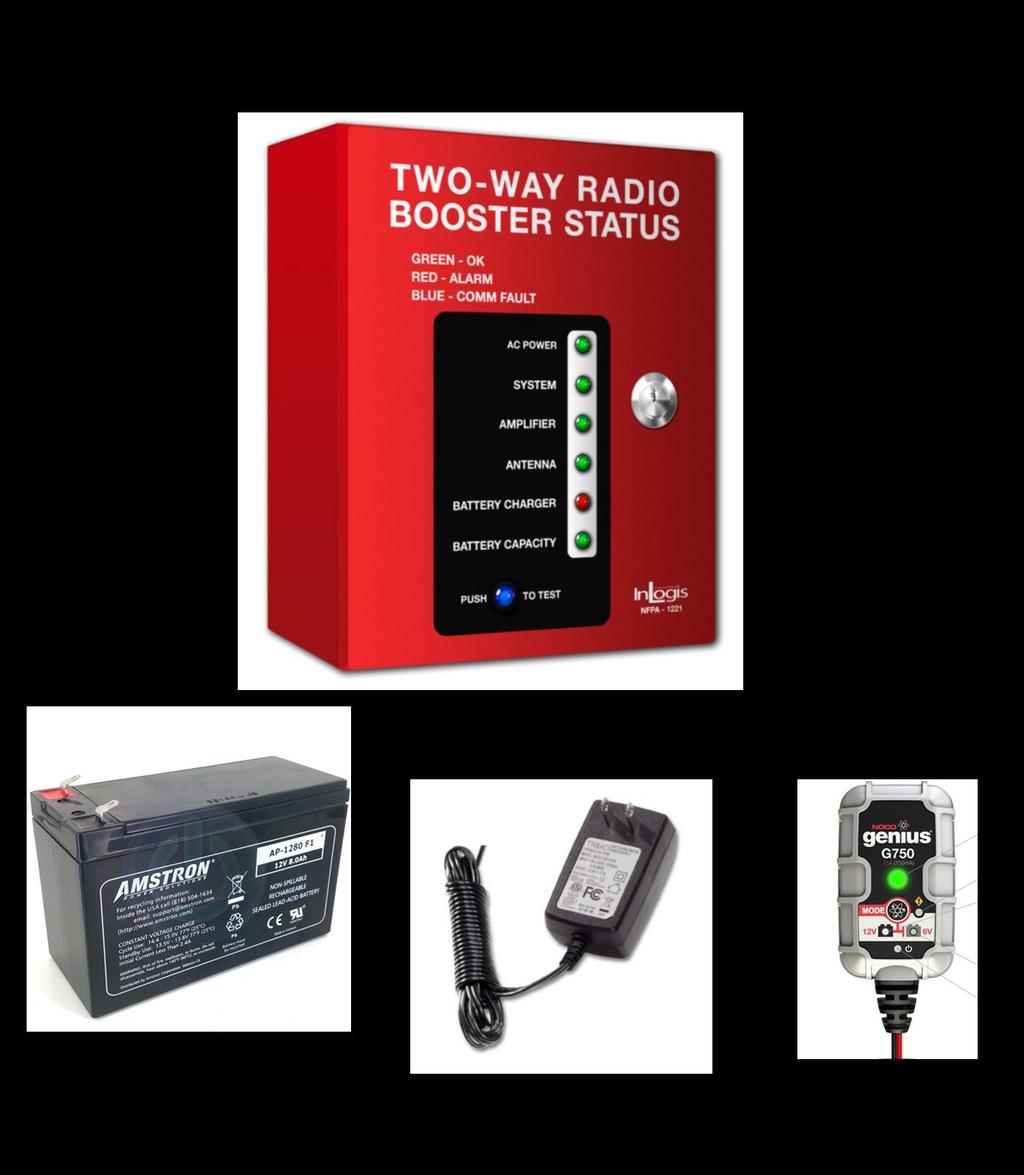
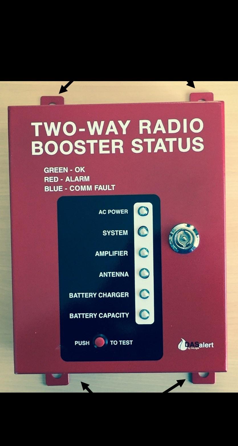
4 Model 1221-A and 1221-B Independent DAS Annunciator Panel Included Items: This panel is designed to meet the requirements of NFPA -72 (versions 2010, 2013 and 2016), and the 2016 version of NFPA It consists of several component sections that enable its use with many different types of BDA s and backup power supplies / UPS. It also has the capability to support DAS installations that have multiple amplifiers and donor antennas. Physically the panel modules consist of two printed circuit boards: the LED Board which is mounted on the back side of the door and the Mother Board that is mounted inside the main body of the enclosure. There is a shelf / cavity that holds the included 8 Ahr 12 vdc SLA emergency backup battery. A battery charger and 15 VDC power supply are also included that can be connected to any 120 VAC electrical outlet. Figure 1 shows the main components. Figure 12 shows the other supplied items. (NOTE: If the included key is lost you can open the panel with a standard set of needle nose pliers.) The main system sections are as follows: QTY Description 1 Main Alarm Panel 4 16 pin cable connector 1 8 pin cable connector 1 6 pin DC Power connector 1 Screw Driver for mating wires to connectors 1 8 Ahr 12 vdc SLA backup battery 1 AC socket mount battery charger 1 Trim pot adjustment tool 1 Installation Manual k Ohm 0.25 watt end-of -line resistor 1 15 VDC wall mount power supply 1 Spare 1 amp battery fuse 1 Door latch key 1. HIGH Brightness 3-color (Red, Green, Blue) LED Annunciator Displays Main AC power Loss BDA / Amplifier Alarm Summary System Alarm Antenna Failure DAS Battery Charger Failure DAS Battery Capacity Low (less than 30%) It also provides individual LED indications if there is a communications error (open, disconnected or shorted cable between the panel and the DAS equipment). 2. Communications Integrity Sensors For each alarm input from the BDA or backup power supply a sensor is provided that detects if the cables connecting to these devices are open or disconnected. A set of dry relay Form-C contacts are also provided to communicate this problem to the main fire alarm panel (MFAP). 3. FORM- C Dry Relay Contacts to mate with common Fire Alarm Panels (See Figure 5) These alarm contacts are rated at 1 amp and include provisions for easily installing End of Line Resistors (EOLR) inside the panel. These relays utilize the same signaling format as smoke detectors. So that in the event of an alarm or panel failure the relays will close shorting the end-of line resistor. 4. ANTENNA Failure (Model 1221-A See Figure 6) Since many BDA s lack the capability to detect problems with the donor antenna or its lead-in cable, this panel includes the internal circuitry to provide this functionality if the BDA does not provide it. It mates with user supplied bias T fittings to sense common donor antenna feed problems. 4

5 5
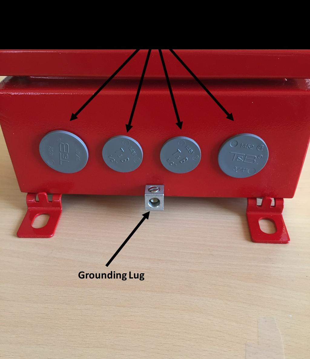
6 5. DAS Backup Battery Charger Failure ( Model 1221-A) If the DAS backup battery charger or UPS does not have a failure sensor, the panel can provide alternative functionality. 6. DAS Backup Battery Capacity less than 30% (Model 1221-A) If the backup power supply or UPS does not have this alarm capability, the panel can provide alternative capability. 7. Backup 24 Hour Panel Power The panel is powered via an external wall mounted 15 VDC power supply. There is also an external Charger provided that keeps an internally mounted 8 Ahr 12 vdc SLA battery charged. In the event of AC power loss, the panel will continue normal operation for at least 24 hours. Although these types of batteries in our application have a lifetime of 4-5 years, best practices call for replacement on an annual basis. Its five-stage charger has LED indicators showing if the battery needs to be replaced or if it has failed for any reason. The panel is designed for a battery with these maximum dimensions: 5.96 L x 2.58 W x 3.65 H or smaller. The replacement battery is available from Amstron (Model AP-1280 F1). The panel s battery also has a method of reporting its failure or its need for replacement to the Main Fire Alarm Panel. This feature can be turned OFF or ON since some installations with alternate backup power do not need this battery. The default mode for this is OFF. (DIP switch SW4-10 ON) 8. NEMA-4 rated wall mounted enclosure The fire codes require that this panel meet the NEMA-4 water resistant requirements. It has four thermoplastic knockouts on the bottom of the panel that provide four openings for standard ½ and ¾ EMT conduit fittings. The panel is provided with brackets to mount it to any wall. Its dimensions are 5.85 H x 7.87 W x 3.98 D and it weighs 11.7 pounds. 9. Test Features A push to test button is provided that will illuminate each of the 3 color LEDs (red, green and blue) for a few seconds in each color. During this test the alarm relays to the main fire alarm panel (MFAP) are also actuated. To statically test the alarm relays there are internal DIP switch settings that will simulate alarms or normal status for the these relays. (see Table 1). Model Differences The panel is available in two different configurations. Model 1221-A and 1221-B. The table below shows the differences. Module Model 1212 A Model 1221 B Annunciator Panel with FORM-C relay outputs to Alternative Donor Antenna Failure Sense Module Alternative DAS Battery Capacity Sense Module Alternative DAS Battery Charger Module Panel Backup Battery (8Ahr) Panel Power Supply and battery Charger Failure Sense 6
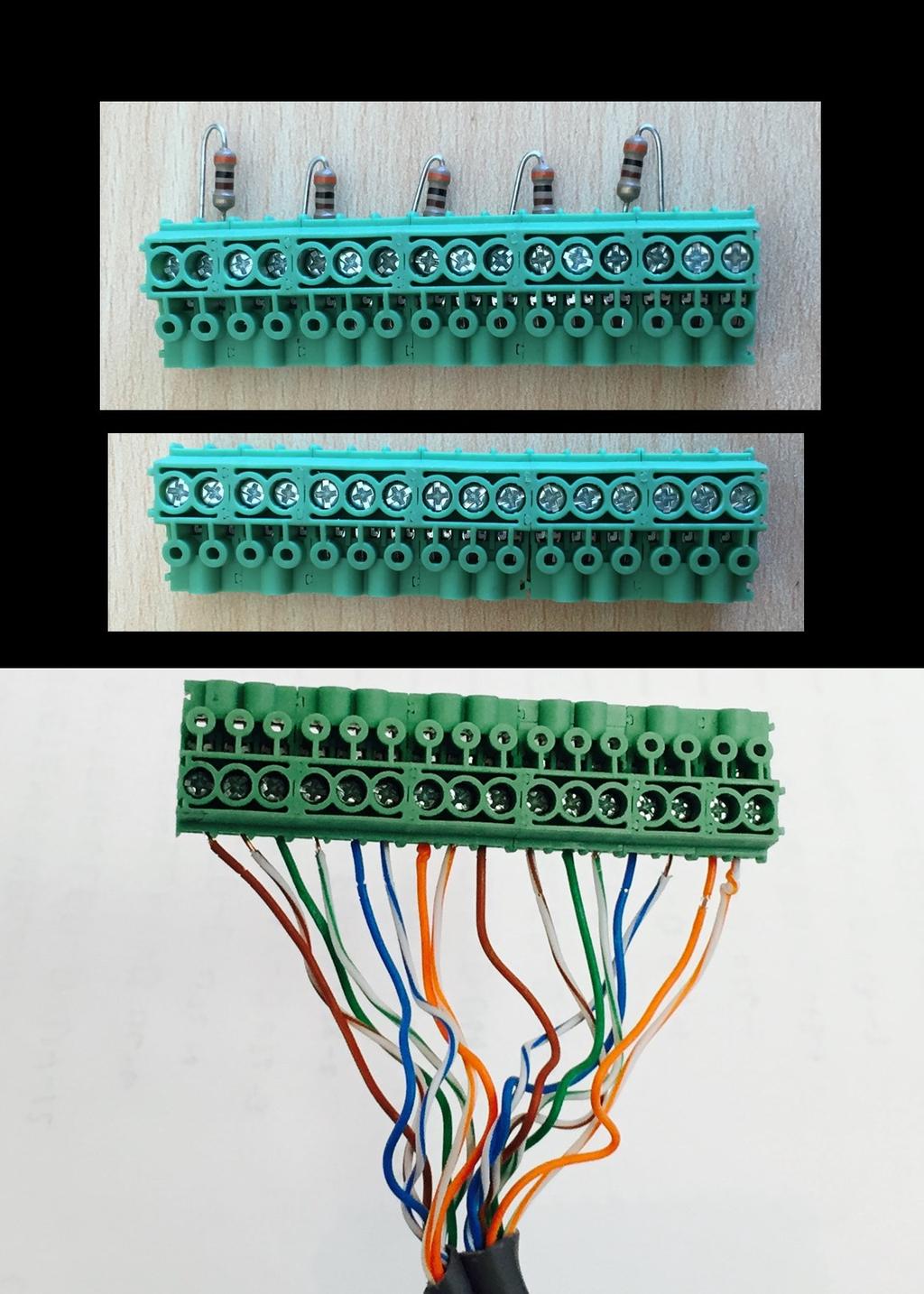
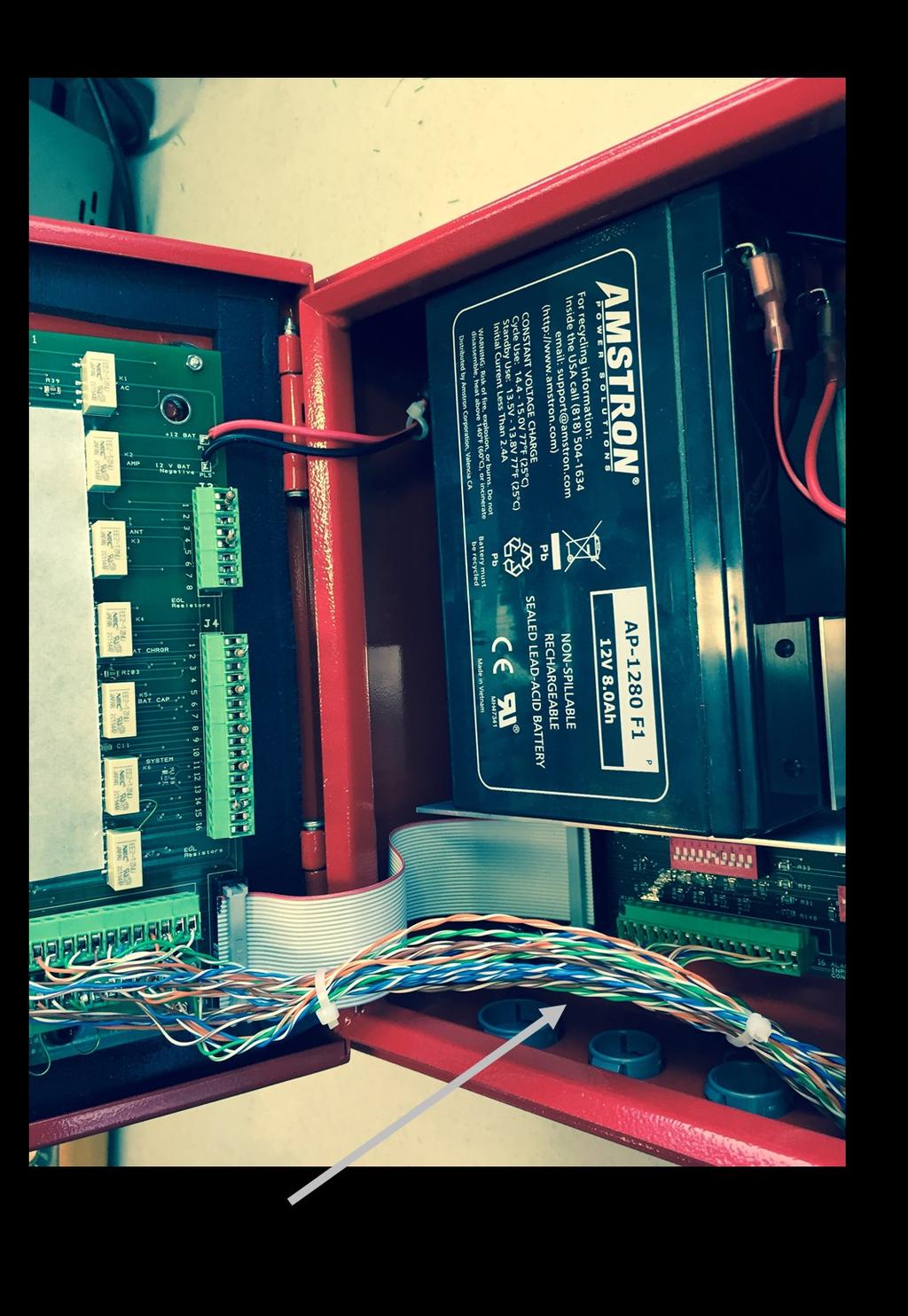
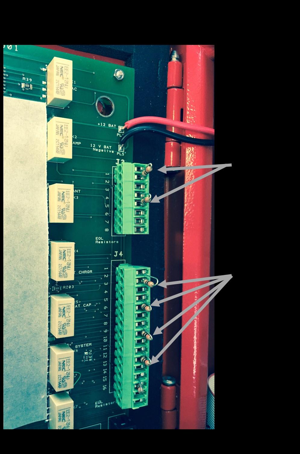
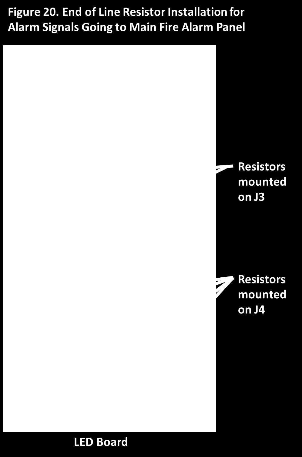
7 Mating with DAS Equipment Figure 2 shows the standard method of mating this panel with a BDA and UPS. The standard method is the same as that used to connect to most Fire Alarm Panels where an end- of- line- resistor (EOLR) is used to sense the alarm status and detect if the cables are open, disconnected or shorted. Most BDA and UPS units are provided with Form- C dry relay contacts that can be connected so if there is an alarm or power failure the relay will close providing a short across the end-of-line resistor. For this panel the EOLR is 10 k Ohms and these are provided with the panel accessories for connection at the DAS equipment. Some BDA or UPS suppliers do not provide Form-C dry relay alarm contacts (See Figure 3). Instead they use Form-A contacts which open when there is an alarm. In this case the panel can be programmed to accommodate this mode by closing the appropriate DIP switch as shown Table 1 in the APPENDIX. Figure 4 shows how to wire to the panel if multiple BDA s or UPS units are utilized in the system. In this configuration, the EOLR is located at the last unit in the daisy chain. In the event it is not possible to install the 10k Ohm EOLR at the DAS equipment, these can be simulated by closing the appropriate DIP switch as shown in Table 1. This method can also be utilized for testing to simulate an OK status input when the DAS equipment is not connected or if one or some of the DAS inputs are not used. Connections to Main Fire Alarm Panel Figure 5 shows the output cable connections from the internal relays to the Main Fire Alarm Panel (MFAP). NOTE: Connectors J2 and J7 on the LED PC board are designed to be directly wired to the MFAP. Connectors J4 and J3 on the LED PC Board are internally connected pin-for-pin to the relays and are intended to hold and connect the end-of-line resistors specified by the MFAP supplier to the relay contacts (See Figure 20). Figure 5 shows the relays in their not energized power off (Alarm) positions. The plugs for these connectors are mated with their headers on the PC boards. To connect them to external wiring a miniature screw driver is included that is used to tighten the wire clamp on each pin. (See Figure 17) The wire clamps will accommodate wire sizes up to 16 AWG in diameter and as small as 26 AWG. Note that these connectors are NOT keyed, so careful attention must be paid to the pin numbers that are marked on the PC board when mating the connector. You also must check that the connector is not offset to insure that all of the appropriate pins of the header are mated with the plug. This is an easy error to make when mating this type of connector. The relays are shown connected to a master fire panel that uses the normal conventional alarm configuration (i.e. when the relays signal an alarm, they are closed causing the EOLR to be shorted). In the unlikely event you are connecting to a panel that uses the opposite convention, the unused contacts on the output relays are also available to connect to and conform to this non-standard convention. Alarm relays are provided for: loss of AC POWER, AMPLIFIER malfunction, DONOR ANTENNA malfunction, DAS Backup battery CHARGER failure, and DAS BATTERY CAPACITY low. Optional alarm relays are provided to signal a COMMUNICATIONS FAULT with the DAS equipment (open, severed or disconnected cable between the annunciator panel and DAS equipment) and a SYSTEM summary alarm that is triggered when any of the other alarms are active. This relay can also be connected to an audible external alarm instead of the fire alarm panel. DIP Switch Settings DIP switches are used to program the functionality of the panel. Unless we have advised you otherwise, the panel is shipped with the standard default factory settings shown in the table on the next page. Details regarding the function of each switch are shown in the APPENDIX. 7
8 DEFAULT FACTORY SETTINGS FOR DIP SWITCHES DIP SWITCH SETTING LOCATION SW1-1 OFF Mother Board SW1-2 OFF Mother Board SW1-3 OFF Mother Board SW1-4 OFF Mother Board SW1-5 OFF Mother Board SW1-6 OFF Mother Board SW1-7 OFF Mother Board SW1-8 OFF Mother Board SW1-9 OFF Mother Board SW1-10 OFF Mother Board SW2-1 OFF Mother Board SW2-2 OFF Mother Board SW2-3 OFF Mother Board SW2-4 OFF Mother Board SW2-5 OFF Mother Board SW2-6 OFF Mother Board SW2-7 ON Mother Board SW2-8 ON Mother Board SW2-9 OFF Mother Board SW2-10 OFF Mother Board SW3-1 OFF Mother Board SW3-2 OFF Mother Board SW3-3 OFF Mother Board SW3-4 OFF Mother Board SW3-5 OFF Mother Board SW3-6 ON Mother Board SW3-7 OFF Mother Board SW3-8 ON Mother Board SW3-9 OFF Mother Board SW3-10 ON Mother Board SW4-1 OFF LED Board SW4-2 OFF LED Board SW4-3 OFF LED Board SW4-4 OFF LED Board SW4-5 ON LED Board SW4-6 ON LED Board SW4-7 OFF LED Board SW4-8 OFF LED Board SW4-9 OFF LED Board SW4-10 ON LED Board 8

9 Model 1221-A or 1221-B 9

10 Model 1221-A or 1221-B DIP Switch Settings for this Mode: SW3-1 ON SW3-2 ON SW3-3 ON SW3-4 ON SW3-5 ON 10
11 Model 1221-A or 1221-B 11
12 Figure 5. Relay and End-of-Line-Resistor Connections to Main Fire Alarm Panel (Model 1221-A or 1221-B) 12
13 Antenna Failure Sense If the BDA in your system does not have the capability to test antenna and lead-in cable failures, this panel can provide an alternative method for detecting most common problems (cable shorted or disconnected). It should be noted that up until the release of the 2016 version of NFPA-1221 there was some ambiguity in the codes relative to this requirement relating to the need to test all the antennas in the system (both indoor and outdoor) or if the code required addressing only the outdoor donor antenna. In the 2016 version, the requirement is clearly stated for the outdoor donor antenna. Detecting problems with the indoor antennas is optional. The method we use involves injecting a DC voltage (10 VDC) onto the lead-in cable at the input to the BDA using a user supplied bias-t. Another bias-t (user supplied) is used outdoors at the antenna to provide a 50 Ohm DC load (See Figure 6). A typical bias-t can be purchased from Mini-Circuits Part # ZNBT-60-1W+. If the cable is shorted or open the detector will sense this and trigger an alarm. If multiple antennas are to be sensed, connect them as shown in Figure 7. Since cable and connector DC resistance may vary in each installation there is a trim pot adjustment provided to null these variables out. The procedure is as follows. On the Mother Board set the DIP switches as follows: SW1-3 ON SW3-6 OFF SW3-7 ON Connect a DC voltmeter to the test points labeled ANT and GROUND.on the LED Board Adjust the trim pot labeled ANT TRIM (R35) on the LED board until the DC voltage reads 5.0 VDC. This voltage has an acceptable window of ±1 VDC, but you should try to adjust it as close to 5.0 VDC as possible This method obviously does not detect all antenna problems such as the antenna being blown down in a storm or a new building being constructed between the donor antenna and the public safety repeater, but it will detect common faults such as a short circuit, a severed cable or a loose connector and it will pass the test that most inspectors employ by simply disconnecting the cable connected to the outdoor donor antenna. 13


14 Figure 6. Model 1221-A Antenna Monitor Connection Diagram Cat 5 or Cat 6 Cable 14


15 Figure 7. Model 1221-A Antenna Monitor Connection Diagram for Multiple Antennas 15
16 DAS Secondary Power Backup Battery Capacity Test (Model 1221-A) The code requires monitoring the DAS backup secondary battery to determine when it has less than 30 % capacity left under normal full load emergency backup conditions (no AC power). If the UPS in the system does not have the capability to do this, the panel provides an alternative technique. (see Figure 8 which shows appropriate connections to the external DAS backup power battery). This method measures the battery voltage and when it reaches a predetermined threshold an alarm is triggered. To enable this mode connect the DAS battery as shown in Figure 8 and set the DIP switches on the Mother board as follows: SW1-10 ON SW3-10 OFF Battery suppliers provide specifications that show how the nominal battery voltage varies as a function of load current and capacity. Different types of batteries from different vendors will have varying specifications. To accommodate this variability a trim pot adjustment is provided on the LED PC board. The table below shows the appropriate DIP switch settings for 48, 24 and 12 VDC systems. Once these switches are set, connect a DC voltmeter to the test points labeled Battery Low Threshold Test Point and Ground. Adjust the trim pot labeled DAS BAT Threshold Adjust (R41) to set the 30% threshold to the require voltage. NOTE: The test point provides the threshold voltage scaled down by a factor of 10. For example, a threshold trigger point of 45 VDC will read 4.50 VDC on your voltmeter. DIP Switch SW-4 on LED Board Settings 12 VDC Battery 24 VDC Battery 48 VDC Battery SW4-1 ON OFF OFF SW4-2 ON OFF OFF SW4-3 OFF ON OFF SW4-4 OFF ON OFF SW4-5 OFF OFF ON SW4-6 OFF OFF ON DAS Battery Charger Failure (Model 1221-A) (On mother Board set SW3-8 OFF and SW3-9 ON) The code requires monitoring the charger used to keep the DAS secondary power battery at full charge in case of AC Power failure. If the UPS in the system does not have the capability to do this, the panel provides an alternative technique. This method measures the battery voltage and when it reaches a predetermined voltage threshold, an alarm is triggered. To enable this mode set DIP Switch SW3-8 on the Mother board to OFF and SW3-9 on the Mother board to the ON position. Different types of batteries and chargers from different vendors will have varying performance. To accommodate this variability a trim pot adjustment is provided on the LED PC board. The table above shows the appropriate DIP switch settings for 48, 24 and 12 VDC systems. Once these switches are set, connect a DC voltmeter to the test points labeled Charger Bad Threshold and Ground. Adjust the trim pot labeled DAS Charger Threshold Adjust to set the desired threshold to the require voltage. NOTE: The test point provides the threshold voltage scaled down by a factor of 10. For example, a threshold trigger point of 52 VDC will read 5.20 VDC on your voltmeter. To determine the appropriate threshold, you should run a test to measure the nominal battery voltage when the charger is on vs when the charger is turned off or disconnected. The battery voltage should be lower when the charger is off and the battery is under load.. 16

17 Figure 8. Model 1221-A Battery and Charger Monitor Connection Diagram Model 1221-A 17
18 AC Power Loss Alarm (Model 1221-A and Model 1221-B) There are two methods that can be used to detect loss of AC Power: 1. Connect the panel to an external DAS device (BDA or UPS) that provides Form-C relay contacts to signal an alarm. Figure 2 shows these connections. This is the default mode and the panel is shipped with the DIP switches set to enable this mode. 2. Use the loss of AC power to the panel s 15 VDC power supply to sense AC power loss. To enable this mode, on the Mother Board set DIP switch SW1-1 ON and SW1-6 to ON 18
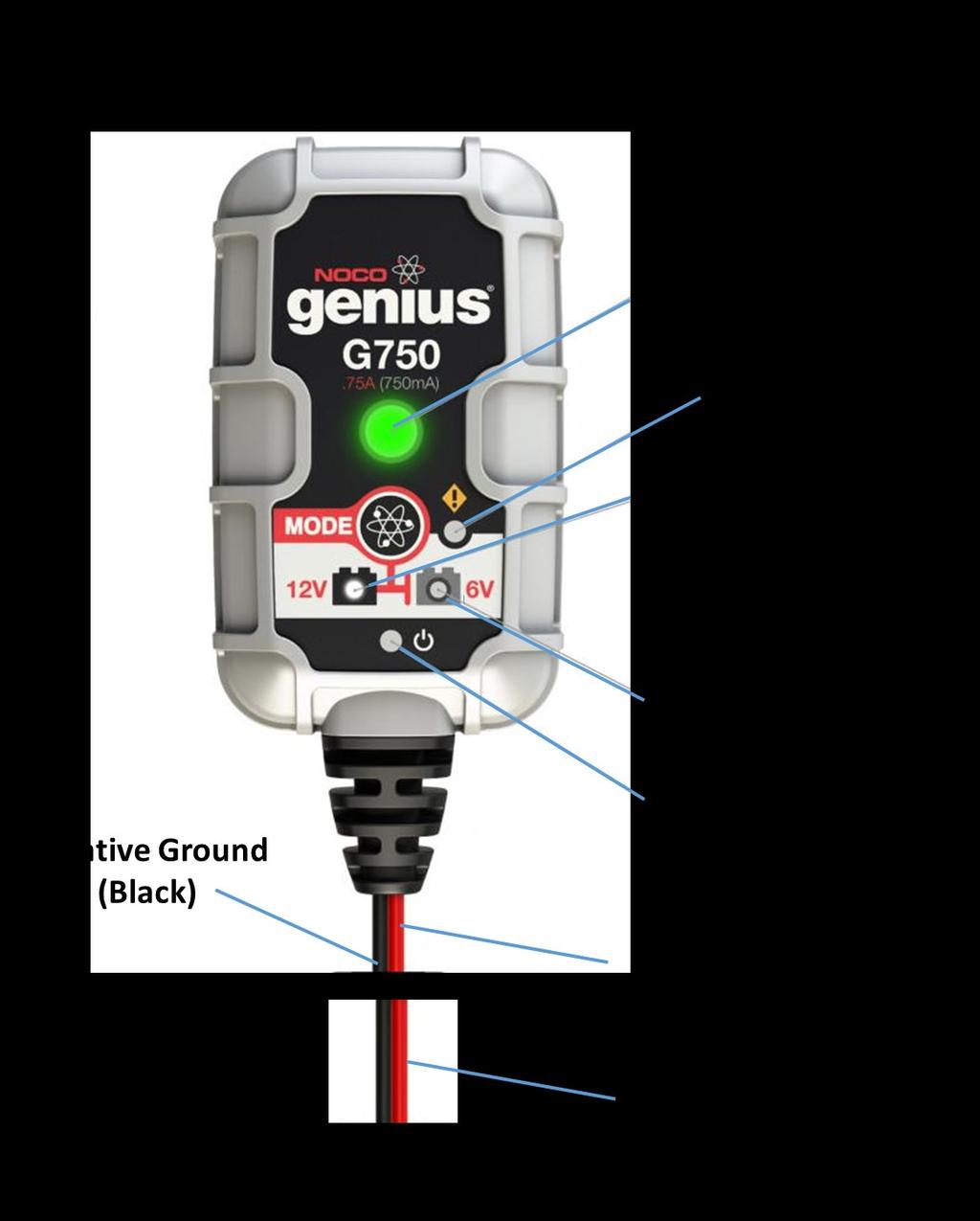
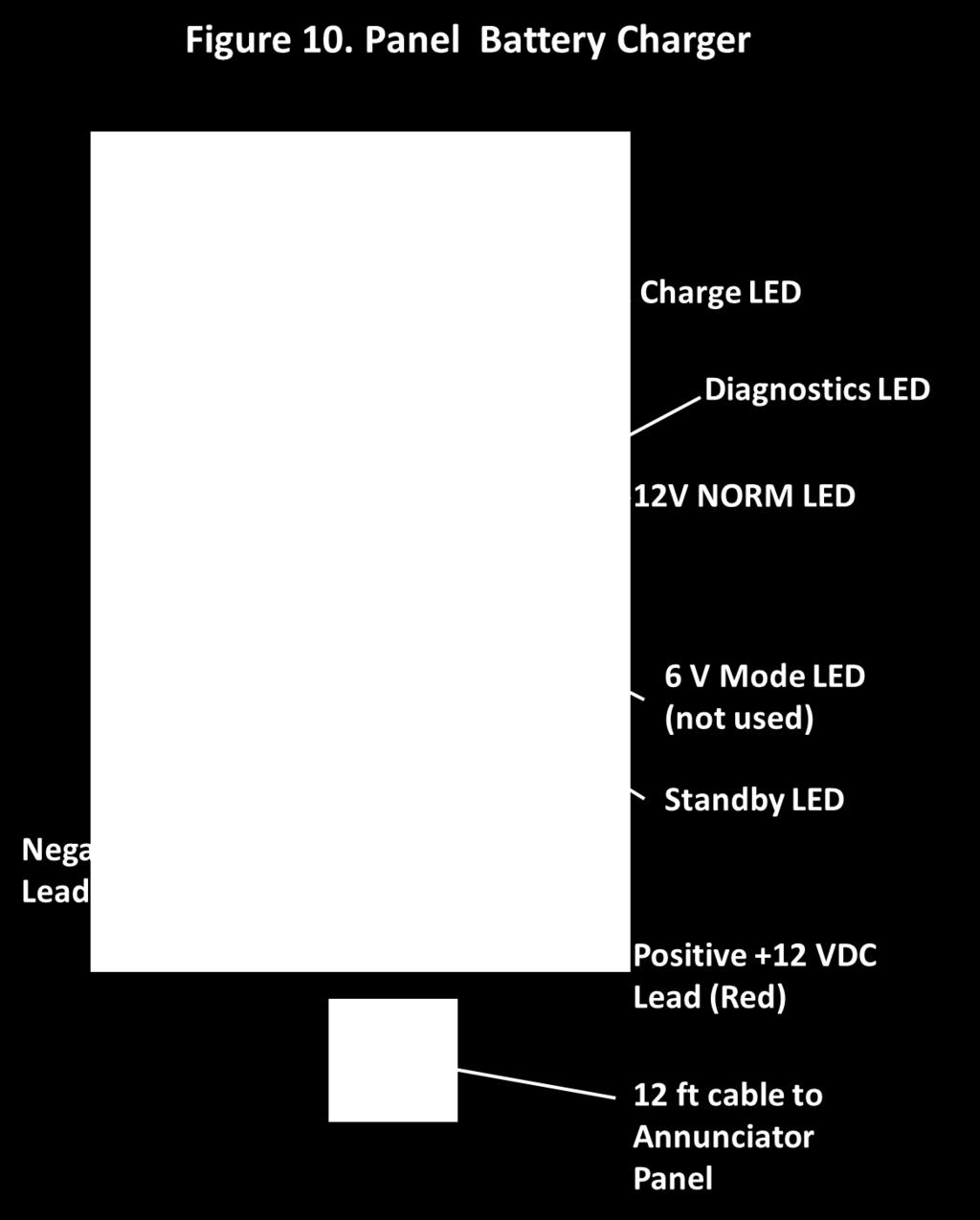
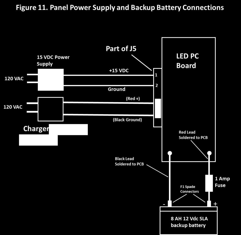
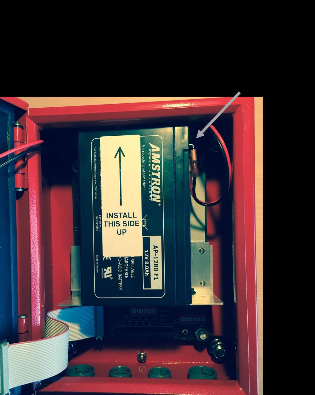
19 Panel Power Supply and Battery Charger The panel s backup battery charger is shown in Figure 10. When doing an installation connect these items last after you have determined that everything else is working correctly on the 15 VDC power supply. This will help eliminate the possibility that the battery s external fuse might blow if something is not wired correctly. The G750 charger is a direct wall plug-in charger, with 12 feet of DC cable attached. The red lead is the positive (nominally +12 to 15 Vdc) output while the black lead is the negative or ground connection. Figure 11 shows how it should be connected to the panel and attached to pins 3 and 4 of the J5 connector on the LED PC Board. Attach the battery to the red and black leads that are soldered to the LED board as shown in Figure 11. Place the battery into its holder making sure that all wire connections and the battery s 1 amp fuse are routed around and below the surface of the battery case to ensure they will not interfere with closing the door of the panel or damage any components on the LED PC board when the door is completely closed and latched. See Figures 13, 14 and 19. When the battery is connected and the charger is powered, the charger LED after a few seconds will blink red to indicate the battery is charging. When the battery is nearly charged it will blink green and eventually turn solid green when the battery is fully charged. The diagnostics LED on the charger provides the following indications: Single Flash: Battery will not hold a charge Double Flash: Possible battery short Triple Flash: Battery voltage is too high for the selected charge mode. Double check the battery is a 12 VDC Sealed Lead Acid type. LED Solid Red: Reverse polarity. Reverse the connections to the battery. The standby LED will be solid Orange if the battery is not connected or its voltage is too low for the charger to detect. There is an option to monitor the status of this battery and notify the building s main fire alarm panel if it is low or needs replacement. This can be done by setting DIP SW4-10 on the LED board to the OFF position. If the battery needs to be replaced or if it is disconnected the SYSTEM LED will flash on and off once per second and the SYSTEM alarm relay will signal an alarm to the building s main fire alarm panel. The circuit that senses this battery s status has a time lag of about 10 seconds. So once the panel s battery is connected or disconnected it will take about 10 seconds before the LED on the panel reacts. Figure 11 also shows how the 15 VDC power supply is attached. End to End Testing. DIP switch settings on the Mother board are provided to simulate various alarm conditions: DIP switch SW1-7 (Normally OFF, when ON all LEDs will be Red and all relay signals to the main fire alarm panel will be forced to the alarm state except the Communications Fault Alarm DIP switch SW1-8 (Normally OFF, when ON all LEDs will be Green and all relay signals to the main fire alarm panel will be forced to the normal non-alarm state. 19
20 Test Points (TP) Test Points (TP) are provided on the LED board to use for troubleshooting and system setup (see Figure 18). These TPs are designed to mate with standard voltmeter probes. Each TP is isolated from the main circuits via a 10k resistor so if a TP is inadvertently shorted, no damage will result. The table below shows the nominal DC signals that can be measured at each TP. Name DC Voltage Comments +14 VDC VDC Approximately 12 VDC when running on panel backup battery. 14 VDC when power supply is active 10 VDC 10 VDC Output of panel's 10 VDC regulator Antenna 5 VDC Nominal level is 5.0 VDC. Will vary as a function of antenna cable length and number of antennas that are monitored.. Use the Antenna trim pot to adjust this voltage to a nominal 5 VDC value DAS Charger Threshold varies Depends on threshold value set to detect DAS Charger failure DAS Battery Low varies Depends on threshold value set to detect DAS battery capacity DAS Battery + Depends on DAS Battery. Connected to DAS battery positive and negative terminals so the status of the DAS Battery - Either 12, 24 or DAS Backup Battery can be measured 48 VDC Ground 0 vdc Connected to circuit ground and enclosure chassis 20
21 21

22 Model 1221-A or 1221-B 22
23 23

24 Figure 13. Mother Board Model 1221-A or 1221-B 24

25 25

26 26

27 27

28 28


29 Figure 18. LED Board Model 1221-A or 1221-B 29
30 30
31 31
32 Table 1. DIP Switch Settings DIP Switch SW4-1 SW4-2 SW4-3 SW4-4 SW4-5 SW4-6 SW4-7 SW4-8 SW4-9 SW4-10 LED PC Board Function 12 VDC Battery 12 VDC Battery 24 VDC Battery 24 VDC Battery 48 VDC Battery 48 VDC Battery Not Used Not Used Not Used Normally ON, OFF enables monitoring of Panel Battery Status DIP Switch SW1-1 SW1-2 SW1-3 SW1-4 SW1-5 SW1-6 SW1-7 SW1-8 SW1-9 SW1-10 SW2-1 SW2-2 SW2-3 SW2-4 SW2-5 SW2-6 SW2-7 SW2-8 SW2-9 SW2-10 Mother PC Board Function Normally OFF, ON places 10 k Ohm EOLR across AC Alarm input Normally OFF, ON places 10 k Ohm EOLR across BDA-Amplifier Alarm input Normally OFF, ON places 10 k Ohm EOLR across Antenna Alarm input from BDA Normally OFF, ON places 10 k Ohm EOLR across DAS Battery Charger Alarm input Normally OFF. ON places 10 k Ohm EOLR across DAS Battery Capacity Alarm input Normally OFF, ON enables 15 VDC Power Supply to trigger AC power loss Alarm. SW1-1 must be also be ON Normally OFF, ON forces all output relays into Alarm mode (RED LEDS) Normally OFF, ON forces all output relays to the MFAP into the OK state (GREEN LEDS) Normally OFF, ON forces a Communications Fault Alarm to the MFAP (BLUE LEDS) Normally OFF, ON connects internal Battery Capacity sensor to MFAP, In the ON state SW3-10 must be OFF. Normally OFF, ON disables AC Power Blue LED Normally OFF, ON disables AMPLIFIER Blue LED Normally OFF, ON disables ANTENNA Blue LED Normally OFF, ON disables CHARGER Blue LED Normally OFF, ON disables BATTERY CAPACITY Blue LED Normally OFF, ON for use with CommScope NODE A amplifiers Normally ON, OFF for use with CommScope NODE A amplifiers Normally ON, OFF for use with some UPS's NOT USED ALWAYS OFF SW3-1 SW3-2 SW3-3 SW3-4 SW3-5 SW3-6 SW3-7 SW3-8 SW3-9 SW3-10 Normally OFF, ON reverses polarity of external AC power loss alarm input from DAS Normally OFF, ON reverses polarity of DAS BDA-Amplifier alarm input Normally OFF, ON reverses polarity of external DAS Antenna fail alarm input Normally OFF, ON reverses polarity of external DAS Battery Charger alarm input Normally OFF, ON reverses polarity of external DAS Battery Capacity low alarm input Normally ON to connect external DAS Antenna Fail alarm to the MFAP. In the ON state SW3-7 must be OFF Normally OFF, ON connects internal DAS Antenna Fail sensor alarm to the MFAP. In the ON state SW3-6 must be OFF Normally ON to connect external DAS Battery Charger Fail alarm to the MFAP. In the ON state SW3-9 must be OFF Normally OFF, ON connects internal DAS Battery Charger Fail sensor alarm to the MFAP. In the ON state SW-3-8 must be OFF. Normally ON, connects external Battery Capacity sensor to the MFAP. In the ON state SW1-10 must be OFF 32
33 Connector Pin Assignments and Functions J1 on Mother PC Board (Inputs from DAS Equipment) PIN # Function / Name 1 AC Power Loss +10 VDC Excite (to UPS) 2 AC Power Loss input (from UPS) 3 BDA-Amplifier Fail +10 VDC Excite (to BDA) 4 BDA-Amplifier Fail input (from BDA) 5 Antenna Fail Alarm +10 VDC Excite (to BDA) 6 Antenna Fail Alarm input (from BDA) 7 DAS Battery Charger Fail +10 VDC Excite (to UPS) 8 DAS Battery Charger Fail Alarm (from UPS) 9 DAS Battery Capacity Low +10 VDC Excite (to UPS) 10 DAS Battery Capacity Low Alarm (from UPS) 11 Not used 12 Not used 13 Not used 14 Not used VDC Power for SNMP Module 16 Not used J2 on LED PC Board (Relay outputs to Main Fire Alarm Panel) PIN # Function / Name 1 AC Fail (COMMON) Alarm relay 2 AC Fail (N.C.) Alarm Relay Contact (closed to common when in alarm or not powered) 3 AC Fail (N.O.) alarm Relay Contact (open to common when in alarm or not powered) 4 BDA-Amplifier (COMMON) Fail Alarm relay 5 BDA-Amplifier (N.C.) Fail Alarm Relay Contact (closed to common when in alarm or not 6 BDA-Amplifier (N.O) Fail Alarm Relay Contact (open to common when in alarm or not 7 Antenna (COMMON) Alarm Relay 8 Antenna Alarm (N.C.) Relay Contact (closed to common when in alarm or not powered) 9 Antenna Alarm (N.O) Relay Contact (open to common when in alarm or not powered) 10 DAS Charger (COMMON) Alarm Relay 11 DAS Charger (N.C.) Alarm Relay Contact (closed to common when in alarm or not pow- 12 DAS Charger Alarm Relay (N.O.) Contact (open to common when in alarm or not 13 DAS Battery Capacity (COMMON) Alarm Relay 14 DAS Battery Capacity (N.C.) Alarm Relay Contact (closed to common when in alarm or not 15 DAS Battery Capacity (N.O.) Relay Contact (open to common when in alarm or not 16 Not used 33
34 Connector Pin Assignments and Functions (continued) J4 on LED PC Board (End of Line Resistor-EOLR contacts) PIN # Function / Name 1 EOLR (COMMON) connection for AC Fail Alarm relay 2 EOLR (N.C.) connection for AC Fail Alarm Relay Contact (closed to common when in alarm or not powered) 3 EOLR (N.O.) connection for AC Fail Alarm Relay Contact (open to common when in alarm or not powered) 4 EOLR (COMMON) connection for BDA-Amplifier Fail Alarm relay 5 EOLR (N.C.) connection for BDA-Amplifier Fail Alarm Relay Contact (closed to common when in alarm or not powered) 6 EOLR (N.O.) connection for BDA-Amplifier Fail Alarm Relay Contact (open to common when in alarm or not powered) 7 EOLR (COMMON) connection for Antenna Alarm Relay 8 EOLR (N.C.) connection for Antenna Alarm Relay Contact (closed to common when in alarm or not powered) 9 EOLR (N.O.) connection for Antenna Alarm Relay Contact (open to common when in alarm or not powered) 10 EOLR (COMMON) connection for DAS Charger Alarm Relay common 11 EOLR (N.C.) connection for DAS Charger Alarm Relay Contact (closed to common when in alarm or not powered) 12 EOLR (N.O.) connection for DAS Charger Alarm Relay Contact (open to common when in alarm or not powered) 13 EOLR (COMMON) connection for DAS Battery Capacity Alarm Relay 14 EOLR (N.C.) connection for DAS Battery Capacity Alarm Relay Contact (closed to common when in alarm or not powered) 15 EOLR (N.O.) connection for DAS Battery Capacity Relay Contact (open to common when in alarm or not powered) 16 Not used 34
35 Connector Pin Assignments and Functions (continued) J7 on LED PC Board (Relay outputs to Main Fire Alarm Panel) PIN # Function / Name 1 System Summary (COMMON) Alarm relay 2 System Summary (N.C.) Alarm Relay Contact (closed to common when in alarm or not 3 System Summary (N.O.) Alarm Relay Contact (open to common when in alarm or not 4 Communications Fault (COMMON) Alarm relay 5 Communications Fault (N.C.) Alarm Relay Contact (closed to common when in alarm 6 Communications Fault (N.O) Alarm Relay Contact (open to common when in alarm or 7 Not used 8 Shield connection from Bias- T 9 Center conductor connection from Bias-T 10 Not used 11 Not Used 12 Ground 13 Ground VDC Output VDC output 16 Not used J3 on LED PC Board (End of Line Resistor-EOLR contacts) PIN # Function / Name 1 EOLR (COMMON) connection for System Summary Alarm relay 2 EOLR (N.C.) connection for System Summary Alarm Relay Contact (closed to common when in alarm or not powered) 3 EOLR (N.O.) connection for System Summary Alarm Relay Contact (open to common when in alarm or not powered) 4 EOLR (COMMON) connection for Communication fault Alarm relay 5 EOLR (N.C.) connection for Communications fault Contact (closed to common when in alarm or not powered) 6 EOLR (N.O.) connection for Communications fault Contact (open to common when in alarm or not powered) 7 Not used 8 Not used 35
36 Connector Pin Assignments and Functions (continued) J5 on LED PC Board (DC Power) PIN # Function / Name VDC from external power supply 2 Ground from external power supply 3 Panel Battery Charger (+) RED 4 Panel Battery Charger (-) BLACK 5 DAS Backup Battery (+) positive terminal 6 DAS Backup Battery (-) negative terminal 36
37 Specifications Dimensions Weight Form-C (1 amp) dry relay outputs to Main Fire Alarm Panel 9.84" H x 7.87" W x 3.98"D 11.7 Lbs 120 VAC Power System Fault Amplifier Antenna Battery Charger Battery Capacity Communications Error Alarm Inputs from DAS Antenna OK / Fail Amplifier / BDA OK/ Fail Charger OK /Fail Battery capacity OK / Low 120 VAC OK / Fail Analog inputs Antenna sense DAS Backup Battery +/- Power 15 milliamps from supplied external power supply 24 HR backup SLA Battery supplied Certifications UL : E194432, ETL
Public Safety DAS Annunciator Panel
 Public Safety DAS Annunciator Panel 120 VAC Models: 1221-A, 1221-B, 1221-C Revision D 91117 48 VDC Models: 1221-A-48, 1221-B-48, 1221-C-48 24 VDC Models: 1221A-24, 1221-B-24, 1221-C-24 CAUTION: (Read This
Installation Guide for AL600ULM. Multi-Output Access Control Power Supply Charger. Rev
 Installation Guide for AL600ULM Multi-Output Access Control Power Supply Charger Rev. 091800 1 AL600ULM - Multi-Output Access Control Power Supply/Charger Overview: The AL600ULM multi-output access control
FlashGuard 3000B Dual Lighting System Troubleshooting Guide
 FlashGuard 3000B Dual Lighting System Troubleshooting Guide Table of Contents Section Flashhead (Strobe) Troubleshooting Flowchart 1 Multiple Strobe Troubleshooting Flowchart 2 Sidelight Troubleshooting
TECHNICAL DATA. Humidity: 85% Relative Humidity (non-condensing) at 90 F (32 C) maximum.
 at 90 F (32 C) maximum.") September 29, 1997 Firecycle III 433 a 1. PRODUCT NAME VIKING Model E-1 Manufactured 1997 Present 2. MANUFACTURED FOR THE VIKING CORPORATION 210 N Industrial Park Road Hastings, Michigan 49058, U.S.A.
September 29, 1997 Firecycle III 433 a 1. PRODUCT NAME VIKING Model E-1 Manufactured 1997 Present 2. MANUFACTURED FOR THE VIKING CORPORATION 210 N Industrial Park Road Hastings, Michigan 49058, U.S.A.
TECHNICAL DATA OBSOLETE
 Deluge Devices 270a 1. PRODUCT NAME VIKING PAR-3 Available since 1991 2. MANUFACTURED FOR: THE VIKING CORPORATION 210 N. Industrial Park Road Hastings, Michigan 49058 U.S.A. Telephone: (269) 945-9501 (877)
Operating & Maintenance Manual. Alert-4 Ethernet LCD Master Alarm
 Operating & Maintenance Manual Alert-4 Ethernet LCD Master Alarm w w w. a m i c o. c o m Contents User Responsibility 4 Introduction 4 Features 5 Description of the Alarm 5 Shipment Details 5 The Alarm
Installing the Cisco ONS FAP-4 Fuse Alarm Panel
 Installing the Cisco ONS 15454-FAP-4 Fuse Alarm Panel Product Number: 15454-FAP-4= This document explains how to install, test, operate, and maintain the Cisco ONS 15454-FAP-4 fuse alarm panel. This document
Installation Guide for AL400ULM. Multi-Output Access Control Power Supply Charger
 Installation Guide for AL400ULM Multi-Output Access Control Power Supply Charger R AL400ULM - Multi-Output Access Control Power Supply/Charger Rev. 072500 Overview: The AL400ULM multi-output access control
Series. Access Power Controllers. Installation Guide
 Series Access Power Controllers Installation Guide Models Include: Maxim11 - Power Supply 1: 12VDC @ 3.5 amp or 24VDC @ 2.7 amp. - Power Supply 2: 12VDC @ 3.5 amp or 24VDC @ 2.7 amp. - Sixteen (16) fuse
Model 17A00 Expansion Enclosure
 HOME AUTOMATION, INC. Model 17A00 Expansion Enclosure Installation Manual Document Number 17I00-1 Rev A March, 2002 Home Automation, Inc. Model 17A00 Expansion Enclosure Installation Manual Document Number
Installation Guide for AL300ULM. Multi-Output Access Control Power Supply Charger
 Installation Guide for AL300ULM Multi-Output Access Control Power Supply Charger R AL300ULM - Multi-Output Access Control Power Supply/Charger Overview: The AL300ULM multi-output access control power supply/charger
MS-4012/4024 and CMS-4012/4024. Instruction Manual for the. Fire Alarm Control Panels
 R 12 Clintonville Road, Northford, CT 06472 Phone: (203) 484-7161 FAX: (203) 484-7118 Instruction Manual for the MS-4012/4024 and CMS-4012/4024 Fire Alarm Control Panels Document 15586 5/11/93 Revision:
4100U City and Relay Cards Installation Instructions
 4100U City and Relay Cards Installation Instructions Introduction This publication describes the installation procedure for the following: 4100-6031/6032 City Circuit Cards 4100-6033 Alarm Relay Card Inspecting
Multi-Output Access Control Power Supply Charger VDC or 24VDC VDC or 3 24VDC.
 M Series Multi-Output Access Control Power Supply Charger Installation Guide Models Include: AL300ULM AL400ULM - 2.5 amp @ 12VDC or 24VDC. - 4 amp @ 12VDC or 3 amp @ 24VDC. AL600ULM AL1012ULM - 6 amp @
Installation Guide for models:
 140 58th St. Brooklyn, NY Access Power Controllers with Power Supplies Installation Guide for models: Maximal3FD - 12VDC @ 4.6 amp or 24VDC @ 5.2 amp. - Sixteen (16) PTC protected power-limited outputs.
Installation Guide for models:
 140 58th St. Brooklyn, NY Access Power Controllers with Power Supplies Installation Guide for models: Maximal11F - Power Supply 1: 12VDC @ 3.3 amp or 24VDC @ 3.6 amp. - Power Supply 2: 12VDC @ 3.3 amp
Installation and Operation Manual Low Power (LP) DC Power System
 DC Power System") Installation and Operation Manual Low Power (LP) DC Power System LPS Power Enclosure LPB Battery Enclosure 2051259 R3 Information in this document is subject to change without notice and does not represent
Installation and Operation Manual Low Power (LP) DC Power System LPS Power Enclosure LPB Battery Enclosure 2051259 R3 Information in this document is subject to change without notice and does not represent
21-light Remote Annunciator. Owner s Manual
 21-light Remote Annunciator Owner s Manual Annunciator Description... Inside Font Cover Detailed Specifications... 1 Environmental Specifications... 1 Power Supply Requirements... 1 Communication With
MODEL B2 INSTALLATION MANUAL
 RELEASE DEVICES GENERAL DESCRIPTION MODEL B2 INSTALLATION MANUAL S/N: The B2 Series Time Delay Release Devices are UL Listed, Canadian Listed, and CSFM Listed for use on rolling doors, single-slide and
PSN-1000 & PSN 1000(E) Installation Manual
 Installation Manual") PSN-1000 & PSN 1000(E) Installation Manual Potter Electric Signal Company, LLC St. Louis, MO Customer Service: (866) 240-1870 Technical Support: (866) 956-1211 Fax: (314) 595-6999 www.pottersignal.com
PSN-1000 & PSN 1000(E) Installation Manual Potter Electric Signal Company, LLC St. Louis, MO Customer Service: (866) 240-1870 Technical Support: (866) 956-1211 Fax: (314) 595-6999 www.pottersignal.com
PS6 SERIES. Installation PS6 SERIES. Power Supplies c/w Fire Panel Interface, EOL Trigger and Standby Power Option
 Installation PS6 SERIES Power Supplies PS6 SERIES Power Supplies c/w Fire Panel Interface, EOL Trigger and Standby Power Option Installation and Specifications Manual ISDPS6_SERIES 08121590 PCN15016 R05/15GR
SP-1000X. Panic Device Power Controller Installation Guide. Rev
 TM SP-1000X Panic Device Power Controller Installation Guide Rev. 120213 Overview: SP-1000X will operate up to two (2) 24VDC panic hardware devices simultaneously. It is designed to handle the high current
Multi-Output Access Control Power Supply Chargers VDC or 24VDC VDC or 4 24VDC.
 M Series Multi-Output Access Control Power Supply Chargers Installation Guide Models Include: AL300ULM AL400ULM - 2.5 amp @ 12VDC or 24VDC. - 3 amp @ 12VDC or 4 amp @ 24VDC. AL600ULM AL1012ULM - 6 amp
tcm100, tcm101 Series Temperature Control Modules and PTS100, PTS100/3 Pipe Temperature Sensors Operations Manual
 tcm100, tcm101 Series Temperature Control Modules and PTS100, PTS100/3 Pipe Temperature Sensors Operations Manual This manual covers operation of the tcm100 and tcm101 Series Temperature Control Modules.
FIREFLY II PLUS RELEASE DEVICES INSTALLATION MANUAL
 FIREFLY II PLUS RELEASE DEVICES INSTALLATION MANUAL MADE IN THE U.S.A. U.L. LISTED CANADIAN LISTED CSFM: 7300-1418:100 GENERAL DESCRIPTION SERIAL NUMBER The Cookson Company FIREFLY II PLUS Time Delay Release
MADE IN THE U.S.A. ADVANCE FIRE CONTROL MODEL LM21-AFC MANUAL RELEASE DEVICES TEST WEEKLY TO ASSURE PROPER OPERATION OF RELEASE DEVICE/CONTROL PANEL
 RELEASE DEVICES MADE IN THE U.S.A. ADVANCE FIRE CONTROL MODEL LM21-AFC MANUAL The LiftMaster Fire Control (LM21-AFC) Release Device/Control Panel is UL/CUL listed normally energized fail-safe device incorporating
APS-300 SERIES DUAL VOLTAGE UL 294 LISTED ACCESS CONTROL POWER SUPPLIES
 APS-300 SERIES DUAL VOLTAGE UL 294 LISTED ACCESS CONTROL POWER SUPPLIES POWER SUPPLY AND BATTERY CHARGER AC AND DC STATUS INDICATORS ENOUGH POWER TO SUPPORT UP TO 3 MAGLOCKS OR ELECTRIC STRIKES PLUS REQUIRED
Rack Mount Series Installation Guide
 Rack Mount Series Installation Guide Models Include: Maximal1RHV Maximal1RV - 12VDC @ 4 amp or 24VDC @ 3 amp. - 12VDC @ 4 amp or 24VDC @ 3 amp. - Eight (8) Fuse Protected Outputs. - Sixteen (16) Fuse Protected
F I R E G A R D D C EXTENDED PERFORMANCE RELEASE DEVICE SAFE A N D SECURE
 SAFE A N D SECURE Cornell 100 Elmwood Ave. Crestwood Industrial Park Mountaintop, PA 18707 Tel 800.233.8366 Fax 800.526.0841 Email: cornell@cornelliron.com O W N E R S M A N U A L M O D E L F I R E G A
Remote NAC Power Supply D7038
 Operation and Installation Guide Remote NAC Power Supply D7038 D7038 REMOTE NAC POWER SUPPLY Page 2 2005 Bosch Security Systems Contents Contents 1.0 Overview...5 1.1 Module Control...5 1.1.1 Option Bus
Cautions and Warnings. Introduction 4009 NAC POWER EXTENDER
 Cautions and Warnings DO NOT INSTALL ANY SIMPLEX PRODUCT THAT APPEARS DAMAGED. Upon unpacking your Simplex product, inspect the contents of the carton for shipping damage. If damage is apparent, immediately
Cookson Company 1901 South Litchfield Road Goodyear, AZ Phone:
 Cookson Company 1901 South Litchfield Road Goodyear, AZ 85338 Phone: 800-294-4358 www.cooksondoor.com O W N E R S M A N U A L MODEL FIREFLY III EXTENDED PERFORMANCE RELEASE DEVICE TABLE OF CONTENTS INTRODUCTION
"SS90" SERIES CONTROLS MODEL C INSTALLATION MANUAL
 S S S SS O L I D S S90 TATE ECURITIES, INC SOLID STATE FAIL-SAFE UNIT * PATENT PENDING LISTED U L 99Y9 RESET RELEASING DEVICE SOLID STATE SECURITIES, INC. "SS90" SERIES CONTROLS MADE IN THE U.S.A. MODEL
THE "SS90" SERIES RELEASE DEVICES MODEL B2 INSTALLATION MANUAL
 S S S S S S S S 90 OLID TATE ECURITIES, INC SOLID STATE FAIL-SAFE UNIT * PATENT PENDING LISTED U 99Y9 RESET L RELEASING DEVICE SOLID STATE SECURITIES, INC. THE "SS90" SERIES RELEASE DEVICES MADE IN THE
RPSMLR2 RPSMLR2BB. Panic Device Power Controller Installation Guide LISTED. Rev
 RPSMLR2 RPSMLR2BB Panic Device Power Controller Installation Guide LISTED Rev. 102715 Overview: RPSMLR2BB, RPSMLR2 will operate up to two (2) 24VDC panic hardware devices simultaneously. It is designed
For a red enclosure add an R suffix to the part # e.g. eflow4na8r. Altronix Corp th St. Brooklyn, NY. Installing Company: Service Rep.
 Power Supply/Chargers Installation Guide Models Include: eflow4na8-4a @ 12VDC or 24VDC - Eight (8) Fused Outputs eflow6na8-4a @ 12VDC or 24VDC - Eight (8) Fused Outputs eflow102na8-10a @ 12VDC - Eight
- 4 12VDC or 24VDC VDC or 24VDC - Eight (8) Fused Outputs - Eight (8) PTC Outputs. Installing Company: Service Rep.
 Fused Outputs - Eight (8) PTC Outputs. Installing Company: Service Rep.") 140 58th St. Brooklyn, NY Power Supply/Chargers Installation Guide Models Include: eflow4n/eflow4nx - 4 amp @ 12VDC or 24VDC eflow4n8/eflow4nx8 eflow4n8d/eflow4nx8d - 4 amp @ 12VDC or 24VDC - 4 amp @ 12VDC
140 58th St. Brooklyn, NY Power Supply/Chargers Installation Guide Models Include: eflow4n/eflow4nx - 4 amp @ 12VDC or 24VDC eflow4n8/eflow4nx8 eflow4n8d/eflow4nx8d - 4 amp @ 12VDC or 24VDC - 4 amp @ 12VDC
OPERATION AND INSTALLATION MANUAL
 EX+Plus 2 ZONE, 1AREA EXTINGUISHANT CONTROL PANEL OPERATION AND INSTALLATION MANUAL INTRODUCTION The Premier EX Plus is a 2 zone, single area panel for controlling the release of extinguishing gases in
M O D E L S F I R E G A R D M C V ADVANCE FIRE CONTROL RELEASE DEVICE
 Cookson 100 Elmwood Avenue Crestwood Industrial Park Mountaintop, PA 18707 Phone: 800-233-8366 Fax: 800-526-0841 CornellCookson.com O W N E R S M A N U A L M O D E L S F I R E G A R D M C F I R E G A R
For a red enclosure add an R suffix to the part # e.g. eflow4na8dr. Altronix Corp th St. Brooklyn, NY. Installing Company: Service Rep.
 Power Supply/Chargers Installation Guide Models Include: eflow4na8d - 4A @ 12VDC or 24VDC - Eight (8) PTC Outputs eflow6na8d - 4A @ 12VDC or 24VDC - Eight (8) PTC Outputs eflow102na8d - 10A @ 12VDC - Eight
F PC and AO OUTPUT BOARDS INSTRUCTION MANUAL. Blue-White. Industries, Ltd.
 F-2000 PC and AO OUTPUT BOARDS INSTRUCTION MANUAL Blue-White R Industries, Ltd. 500 Business Drive Huntington Beach, CA 92649 USA Phone: 714-89-8529 FAX: 714-894-9492 E mail: sales@blue-white.com or techsupport@blue-white.com
SIMPLICITY CO CARBON MONOXIDE DETECTION & VENTILATION PANEL
 SIMPLICITY CO CARBON MONOXIDE DETECTION & VENTILATION PANEL USER MANUAL 1 Table of Contents 1 SAFETY INFORMATION...3 1.1 SAFETY PRECAUTIONS DURING NORMAL OPERATION OF PANEL...3 1.3 BATTERY INFORMATION...3
Beacon 200 Gas Monitor Operator s Manual. Part Number: RK Released: 6/6/08
 Beacon 200 Gas Monitor Operator s Manual Part Number: 71-2102RK Released: 6/6/08 Table of Contents Chapter 1: Introduction.................................................3 Overview.............................................................3
AL802ULADA. NAC Power Extender. Installation Guide. (See Application Guide for additional information)
") AL802ULADA NAC Power Extender Installation Guide (See Application Guide for additional information) Rev. 042010 Agency Listings: UL Listed Control Units for Fire Protective Signaling Systems (UL 864).
AL802ULADA NAC Power Extender Installation Guide (See Application Guide for additional information) Rev. 042010 Agency Listings: UL Listed Control Units for Fire Protective Signaling Systems (UL 864).
Booster Power Supply Manual
 Supply Manual DEVELOPED BY COPYRIGHT NOTICE General Signal Building Systems Corporation 6411 Parkland Drive Sarasota, FL 34243 (941) 739-4300 Copyright 1999 General Signal Building Systems Corporation
Carbon Monoxide Transmitter
 Introduction The CO Transmitter uses an electrochemical sensor to monitor the carbon monoxide level and outputs a field-selectable 4-20 ma or voltage signal. The voltage signal may also be set to 0-5 or
MAINTENANCE & TROUBLESHOOTING GUIDE LEAK ALARM CHANNEL DRY OIL WATER AUX ALARM HIGH LOW CRITICAL WATER TANK LEVEL ALARM MODEL LDE-740 ADVANCE PAPER
 PNEUMERCATOR Liquid Level Control Systems Electronic Systems Excluding LC2000 And TMS Series MAINTENANCE & TROUBLESHOOTING GUIDE 400 300 500 FUEL LEVEL LEAK MONITOR 1 200 600 OIL/GAS NORMAL WATER PNEUMERCATOR
AL400ULACM AL600ULACM - 4 amp - 12VDC or 6 amp. - Fused Outputs - Fused Outputs
 ACM Series Access Power Controllers with Power Supplies Installation Guide Models Include: AL400ULACM AL600ULACM - 12VDC @ 4 amp - 12VDC or 24VDC @ 6 amp. or 24VDC @ 3 amp - Fused Outputs - Fused Outputs
AL802ULADA. NAC Power Extender. Installation Guide. (See Application Guide for additional information) Rev
 Rev") AL802ULADA NAC Power Extender Installation Guide (See Application Guide for additional information) Rev. 031703 Overview: The Altronix AL802ULADA is an extremely cost effective 8 amp voltage regulated
AL802ULADA NAC Power Extender Installation Guide (See Application Guide for additional information) Rev. 031703 Overview: The Altronix AL802ULADA is an extremely cost effective 8 amp voltage regulated
RELEASE DEVICE CONTROLS
 RELEASE DEVICE CONTROLS RELEASE DEVICE MODEL C+ INSTALLATION MANUAL UL LISTED CANADIAN LISTED CSFM: 7300-48:00 GENERAL DESCRIPTION: MADE IN THE U.S.A. S/N: The LM0-C+ Release Device/Control Panel is a
AL800ULADA. NAC Power Extender. Installation Guide
 AL800ULADA NAC Power Extender Installation Guide Rev. 122000 AL800ULADA - NAC Power Extender Overview: The Altronix AL800ULADA is an extremely cost effective 8 amp voltage regulated remote power supply/battery
MEGA. cal electronic gas alarm. Installation, Operation, and Maintenance Instructions. Part No Rev. D Pg.
 WARD OXYGEN Installation, Operation, and Maintenance Instructions MEGA medical electronic gas alarm MEGA WARD MEGA medical electronic gas alarm WARD POWER SUPPLY Medical Electronic Gas Alarm OXYGEN SYSTEM
LC1 & 2. Fire Alarm Panel 6\VWHPLQVWDOODWLRQRSHUDWLQJ PDLQWHQDQFH LQVWUXFWLRQV
 LC1 & 2 Fire Alarm Panel 6\VWHPLQVWDOODWLRQRSHUDWLQJ PDLQWHQDQFH LQVWUXFWLRQV ZIRCONLC1 One Zone Conventional Fire Panel ZIRCONLC2 Two Zone Conventional Fire Panel Compliant with EN54-2:1998 & EN54-4:1998
SC-6 Six Supervised Control Module
 INSTALLATION AND MAINTENANCE INSTRUCTIONS SC-6 Six Supervised Control Module SPECIFICATIONS Normal Operating Voltage: Stand-By Current: Alarm Current: Temperature Range: Humidity: Dimensions: Accessories:
THERMAL BUILDING SOLUTIONS EN-TraceTekTTSIM1A-IM-H /16
 TraceTek TTSIM-1A TraceTek Sensor Interface Module with Relay Installation/OPERATION Instructions Approvals and Certifications TYPE NM General Signaling Equipment 76LJ Only AC versions are UL listed and
Installation, Operating and Maintenance Manual
 STATUS ZONES CONTROLS FIRE FAULT DISABLED FIRE 1 2 3 4 5 6 7 8 TEST FAULT DISABLED 1 5 BUZZER SILENCE RESET 1 2 TEST 2 6 LAMP TEST 3 SUPPLY 3 7 SYSTEM FAULT 4 8 SOUNDERS ACTIVATE/ SILENCE 4 FAULTS INSTRUCTIONS
/9308 External Battery Chargers Installation Instructions
 4081-9306/9308 External Battery Chargers Installation Instructions Introduction This publication describes the installation procedure for an External Battery Charger used with the 4100U or 4100ES System.
SAFEPATH SP40/2 D10 D35 AMP P/N P/N Installation, Testing, TONE SW Operation, and W4 Maintenance D54 SHORT
 W1 U8 AC N L SAFEPATH4 F2 IN BAT 24V TB7 TB1 AC TBL STB D11GRN YEL RED F1 D13 D14 AC SW1 SW2 RECORD D34 1 2 3 4 SP40/2 D9 D22 DV D10 D35 BAT MIC W2 ON D37 STB SHORT D39 STB OPEN 1 2 3 R SW3 1 2 3 4 TEL
Installation Guide for AL800UL-ADA. NAC Power Extender. Rev
 Installation Guide for AL800UL-ADA NAC Power Extender Rev. 090500 Overview: The Altronix AL800UL-ADA is an extremely cost effective 8 amps voltage regulated remote power supply /battery charger. The AL800UL-ADA
PS1240x Series Dual Voltage Access Control Power Supply Systems Operating and Installation Instructions Rev D.01
 PS1240x Series Dual Voltage Access Control Power Supply Systems Operating and Installation Instructions Warnings and Notices WARNING - To reduce the risk of fire or electric shock, do not expose this product
Net/X Thermostat Network Installation and Troubleshooting Guide
 Net/X Thermostat Network Installation and Troubleshooting Guide Introduction This document contains basic procedures that can be used when installing the Net/X Thermostat network. It is highly recommended
Fire Safety. Installation Instructions Model SMB-2 Main Control Board OPERATION INSTALLATION
 Fire Safety Installation Instructions Model SMB- Main Control Board OPERATION The SIEMENS Model SMB- board in each MXL-IQ System controls operations and monitors input device identity, network communication,
LiftMaster 300 Windsor Drive Oak Brook, IL LiftMaster.com
 LiftMaster 300 Windsor Drive Oak Brook, IL 60523 LiftMaster.com O W N E R S M A N U A L MODELS LM21AFCB LM21AFCBVB B ADVANCE FIRE CONTROL RELEASE DEVICE FM APPROVED TABLE OF CONTENTS INTRODUCTION General
ICS Regent. Fire Detector Input Modules PD-6032 (T3419)
") ICS Regent Fire Detector Input Modules (T3419) Issue 1, March, 06 Fire detector input modules provide interfaces for 16 fire detector inputs such as smoke detectors, flame detectors, temperature detectors,
ICS Regent Fire Detector Input Modules (T3419) Issue 1, March, 06 Fire detector input modules provide interfaces for 16 fire detector inputs such as smoke detectors, flame detectors, temperature detectors,
Installation and user manual for the FX range of fire panels. 1, 2, 4 and 8 zone panels
 Installation and user manual for the FX range of fire panels 1, 2, 4 and 8 zone panels Contents Panel installation 3 Panel connections 3 Wiring connection drawings 4 Panel facilities 6 Installation check
POWERPATH PS-8 (105531) PS-8E (100263) PS-6 (105530) PS-6E (100262)
 PS-8E (100263) PS-6 (105530) PS-6E (100262)") PATH PS-8 (105531) PS-8E (100263) PS-6 (105530) PS-6E (100262) NAC ETENDER SUPPLIES Installation Instructions 273 Branchport Avenue, Long Branch, NJ 07740-6899 Ph: (800) 631-2148 Fax: (732) 222-8707 Web
PATH PS-8 (105531) PS-8E (100263) PS-6 (105530) PS-6E (100262) NAC ETENDER SUPPLIES Installation Instructions 273 Branchport Avenue, Long Branch, NJ 07740-6899 Ph: (800) 631-2148 Fax: (732) 222-8707 Web
IDP-Zone-6 Six Zone Interface Module
 INSTALLATION AND MAINTENANCE INSTRUCTIONS IDP-Zone-6 Six Zone Interface Module BEFORE INSTALLING If the modules will be installed in an existing operational system, inform the operator and local authority
Refrigeration Controller Operator s Manual (HRC) PO Box 6183 Kennewick, WA
 PO Box 6183 Kennewick, WA") Refrigeration Controller Operator s Manual (HRC) PO Box 6183 Kennewick, WA 99336 www.jmcvr.com 1-509-586-9893 Table of Contents TABLE OF FIGURES...1 OVERVIEW OF THE HRC CAPABILITIES...2 INSTALLATION AND
Refrigeration Controller Operator s Manual (HRC) PO Box 6183 Kennewick, WA 99336 www.jmcvr.com 1-509-586-9893 Table of Contents TABLE OF FIGURES...1 OVERVIEW OF THE HRC CAPABILITIES...2 INSTALLATION AND
DSGH. Radiation-Based Detector with GEN2000 Electronics for Density Measurement QUICK REFERENCE GUIDE
 DSGH Radiation-Based Detector with GEN2000 Electronics for Density Measurement QUICK REFERENCE GUIDE Revision History Revision History Version of manual Description Date 1.0 Initial release 051025 1.1
Installation and user manual for the CF5000, MF5000 and FXP5000 range of fire panels
 CF5000, MF5000 and FXP5000 Installation and user manual for the CF5000, MF5000 and FXP5000 range of fire panels 16 zone panels Contents PANEL INSTALLATION...3 Installation...3 PANEL WIRING... 3 Mains power
Networked Access Control Panel. Installation Guide
 XP2M Networked Access Control Panel V1.0X Installation Guide X P 2 M A C C E S S C O N T R O L S Y S T E M Installation Guide Document Ref: PLAN XP2M Installation Guide V4(G)2010 Access Control Services
30.45 Electric Release PDRP-2001
 The PDRP-2001 Fire Alarm Control Panel (FACP) is a six-zone control panel for single and dual hazard deluge and preaction applications. The FACP is compatible with conventional input devices (2-wire or
General Routing Interface
 General Routing Interface Features The General Routing Interface Card is an optional module to provide Fire and Fault Routing Outputs compliant with BSEN54-2: 1998 Clauses 7.9 and 8.9 and BS5839-1: 2002.
AL600ULADA. NAC Power Extender. Installation Guide
 AL600ULADA NAC Power Extender Installation Guide Rev. 122000 AL600ULADA - NAC Power Extender Overview: The Altronix AL600ULADA is an extremely cost effective 6.5 amp voltage regulated remote power supply/battery
LDM Series Lamp Driver Modules For Graphic Annunciation and Control
 12 Clintonville Road Northford, CT 06472 (203) 484-7161 FAX: (203) 484-7118 LDM Series Lamp Driver Modules For Graphic Annunciation and Control Used with the System 500, System 5000, AM2020/AFP1010 and
LED Driver Module. These instructions contain procedures to follow in order to avoid personal injury and damage to equipment.
 LED Driver Module Installation Guide 1.0 Notice These instructions are for installing Radionics LED Driver Module in a fire alarm system controlled by Radionics D8024 or D10024 Fire Alarm Control Panels
TTSIM-2 TRACETEK SENSOR INTERFACE MODULE WITH LCD AND RELAY INSTALLATION/OPERATION INSTRUCTIONS
 TTSIM-2 TRACETEK SENSOR INTERFACE MODULE WITH LCD AND RELAY INSTALLATION/OPERATION INSTRUCTIONS GENERAL INFORMATION Please read these instructions and keep them in a safe place. These instructions must
INSTALLATION INSTRUCTIONS
 TT-1343 5/06b INSTALLATION INSTRUCTIONS Original Issue Date: 8/03 Model: Automatic Transfer Switches Equipped with Series 1000 Programmable Controller Market: ATS Subject: Remote Annunciator Kits GM28938-KP1,
Installation Instructions. PS902 Power Supply. These instructions cover the following parts: PS902 Power Supply Specifi cations:
 F1! 44487023 These instructions cover the following parts: PS902 Power Supply Installation Instructions! DANGER: To avoid risk of electric shock, turn off AC power before installing or servicing PS902
TTSIM-1A. TraceTek Sensor Interface Module with Relay. Installation/Operation Instructions. Installation Items (not supplied) Tools Required.
 Tools Required.") TTSIM-1A TraceTek Sensor Interface Module with Relay Installation Items (not supplied) General Information Installation/Operation Instructions Please read these instructions and keep them in a safe place.
TTSIM-1A TraceTek Sensor Interface Module with Relay Installation Items (not supplied) General Information Installation/Operation Instructions Please read these instructions and keep them in a safe place.
20 Light Remote Annunciator
 Light Remote Annunciator Owner s Manual Surface Mount Flush Mount 94-95- Standard Annunciator 94-, 94-95-, 95-4- 4- Annunciator w/remote Relay Panel 4-, 4-4-, 4-49-, 49-49-, 49- Time Multiplexed Annunciator
AL600ULX Series. Power Supply/Charger. Installation Guide
 AL600ULX Series Power Supply/Charger Installation Guide Models Include: AL600ULX - Single Output AL600ULPD4 AL600ULPD4CB - Four (4) Fused Outputs - Four (4) PTC Outputs AL600ULPD8 AL600ULPD8CB - Eight
ACSI AO ELECTRIC LATCH RETRACTION CONTROLLER INSTALLATION INSTRUCTIONS I.D. 1089, REV. F
 II 1400-2 ACSI 1406-04-AO ELECTRIC LATCH RETRACTION CONTROLLER INSTALLATION INSTRUCTIONS I.D. 1089, REV. F INSTALLATION Transformer Model BE31763001 by Basler Electric, Transformer Model 2010028 by Galaxy
RAZOR RZR SERIES DIE CAST ALUMINUM LED EXIT SIGNS INSTALLATION AND OPERATING INSTRUCTIONS IMPORTANT SAFEGUARDS READ AND FOLLOW ALL SAFETY INSTRUCTIONS
 RAZOR RZR SERIES DIE CAST ALUMINUM LED EXIT SIGNS INSTALLATION AND OPERATING INSTRUCTIONS IMPORTANT SAFEGUARDS When using electrical equipment, basic safety precautions should always be followed including
Functional Performance Test
 Fire Alarm Control Panel & Fire Alarm Annunciator Panel Notify all building occupants that testing will be conducted. Fire alarm contractor shall have personnel with 2-way radios at the fire alarm control
Installation and user manual for the BiWire / Conventional Repeater Panel
 Panel EFBWCV-REPEATER Contents Introduction.... 3 Purpose... 3 The Panel.... 3 Indication Equipment (IE).... 3 Power Supply Equipment (PSE).... 4 System Wiring.... 5 Status Indications.... 5 Repeater I/O....
B-40/B-41 Modulating Temperature Controller
 INSTALLATION & OPERATING INSTRUCTIONS B-40/B-41 Modulating Temperature Controller For Raytherm Boilers & Water Heaters H2 514-4001 WH2 2100-4001 Catalog No. 5000.70 Effective: 12-21-11 Replaces: NEW P/N
Hoffman Controls 759-ECM. Installation & Operating Instructions. Introduction. Installation. Pre-Installation Information/ Instruction
 Hoffman Controls Installation & Operating Instructions Introduction CAUTION Failure to read and understand the accompanying instructions and diagrams prior to energizing the Controller may result in permanent
Model PAD-3 Distributed Power Module NAC Expander Installation, Operation, and Maintenance Manual
 Fire Safety Model PAD-3 Distributed Power Module NAC Expander Installation, Operation, and Maintenance Manual Siemens Building Technologies, Inc. Siemens Building Technologies, Ltd. 8 Fernwood Road 2 Kenview
SAFETY INFORMATION AND WARNINGS
 This manual refers to the Model SST-3 control panel manufactured since October 31, 2013, which uses a universal (100 277 VAC; 50/60 Hz) power supply. Older units use a voltage-specific power supply and
EVO192 v3.0 Fire and Burglary What s New
 EVO192 v3.0 Fire and Burglary What s New Compatibility: EVO192 v3.0 TM50 v1.31 K641 v2.41 Overview: CP-01 Compliancy Wiring Diagram The following sections/options have been added to the EVO192 panel. They
SERIES VAC Microprocessor-Based Direct Spark Ignition Control FEATURES APPLICATIONS SPECIFICATIONS DESCRIPTION. Export Information (USA)
") R SERIES 35-70 120 VAC Microprocessor-Based Direct Spark Ignition Control F-35-70 November 2015 FEATURES Safe start with DETECT-A-FLAME flame sensing technology Custom pre-purge and inter-purge timings
R SERIES 35-70 120 VAC Microprocessor-Based Direct Spark Ignition Control F-35-70 November 2015 FEATURES Safe start with DETECT-A-FLAME flame sensing technology Custom pre-purge and inter-purge timings
Door Release Power Supply
 www.protectingpeople.co.uk Door Release Power Supply Engineer / Installation Manual Document: VI55.1 Protecting People Printed : 04/03/2004-1 - Ventcroft Ltd Door Release Power Supply Engineer / Installation
FEC400 Series. Installation Manual
 FEC400 Series Conventional microprocessor controlled fire detection and alarm panels with extinguishing control Installation Manual Version 2.3 / August 2004 Aritech is a GE Interlogix brand. http://www.geindustrial.com/ge-interlogix/emea
RELEASE DEVICES RELEASE DEVICE-WPS MODELS A/B INSTALLATION MANUAL U.L. LISTED CANADIAN LISTED CSFM: :100 GENERAL DESCRIPTION:
 RELEASE DEVICES MADE IN THE U.S.A. RELEASE DEVICE-WPS MODELS A/B INSTALLATION MANUAL U.L. LISTED CANADIAN LISTED CSFM: 7300-1418:100 GENERAL DESCRIPTION: S/N: The "WPS" World Power Series, Time Delay Release
SYSTEM MANUAL FT1-SB. Single Zone Fire Alarm System
 SYSTEM MANUAL FT1-SB Single Zone Fire Alarm System DOCUMENT HISTORY Issue Date Description Written By Checked By Draft 0 2/9/2008 Original Document. A. Shenouda C. Orr Issue 1 4/11/2011 Update drawing
PNC 1000 SERIES 2, 4, 8 Zone Fire Alarm Control Panel
 PNC 1000 SERIES 2, 4, 8 Zone Fire Alarm Control Panel INSTALLATION, OPERATION AND MAINTENANCE MANUAL Version: CN-PM-1000.VER1.1-12/2012 EN54 INFORMATION In accordance with EN 54-2 clause 13.7, the maximum
Operating & Maintenance Manual. Alert-4 Ethernet LCD Master Alarm
 Operating & Maintenance Manual Alert-4 Ethernet LCD Master Alarm Contents User Responsibility 4 Introduction 4 Features 5 Description of the Alarm 5 Shipment Details 5 The Alarm Back Box 5 The Frame/Module
Centaur TM II Cube Slave Alarm Signalling Equipment INSTALLATION GUIDE
 Centaur TM II Cube Slave Alarm Signalling Equipment INSTALLATION GUIDE General Description This guide provides a summary for installing and configuring the Centaur TM Cube Slave Alarm Signalling Equipment
Series SPB Audio Boosters Installation, Testing, Operation, and Maintenance Manual
 Series SPB Audio Boosters Installation, Testing, Operation, and Maintenance Manual Part Number P84748 Assembly Number A84749 Revision C Revision A Copyright 2006 Printed in U.S.A. All rights reserved.