Documentation. Explosion-Protection. for Smoke Detection Panels SDS-4, SDS-8, SDS-12 and Extension Panels SDS-E8, SDS-E12, SDS-E16, SDS-EC16
|
|
|
- Clifton Watson
- 5 years ago
- Views:
Transcription
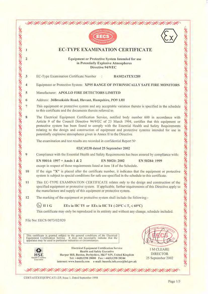
1 safetec Documentation Explosion-Protection for Smoke Detection Panels SDS-4, SDS-8, SDS-12 and Extension Panels SDS-E8, SDS-E12, SDS-E16, SDS-EC16 in Smoke Detection System SDS-48 according IEC Art.No.: DOK File: DOK odt Rev.0 1
2 safetec safetec Brandes und Niehoff GmbH Arenskule Lüneburg Germany Tel.: Fax.: Internet: Autor: Dipl. Ing. (FH) Klaus Brandes List of Revisions No. Date Name Remark kb Document Ex-Protection-SDS-48-Rev7 extended and renamed to DOK Art.No.: DOK File: DOK odt Rev.0 2
3 safetec Content 1 Definition of Zone, Temperature Class and Protection Type Smoke Detection Panels SDS-4, SDS-8, SDS-16 and Extension Units SDS-E8, SDS-E12, SDS- E16, SDS-EC System Description System Analysis Fan Unit SDS-M0440 / SDS-M Attached Documents Drawings Certificates of Conformity...8 Art.No.: DOK File: DOK odt Rev.0 3
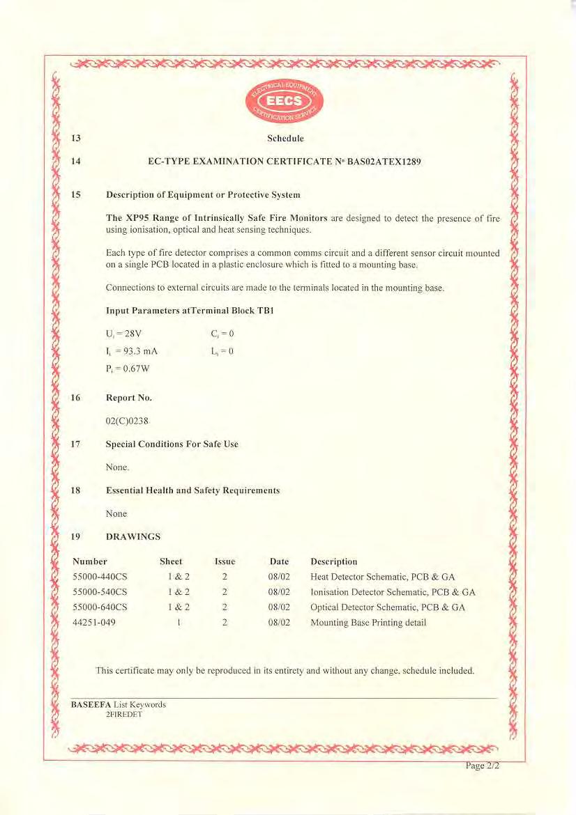
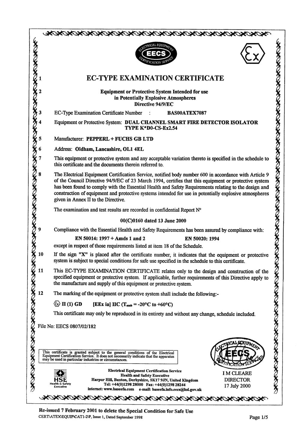
4 safetec 1 Definition of Zone, Temperature Class and Protection Type Hazardous atmosphere in detection unit: Zone 1 Equipment Protection Level: EPL Gb Temperature Class: T5 Environment Temperature: -20 C +45 C Protection Type: Gas - Intrinsic Safety ia acc. IEC Ex Group: IIC 2 Smoke Detection Panels SDS-4, SDS-8, SDS-16 and Extension Units SDS-E8, SDS-E12, SDS-E16, SDS-EC System Description A block diagram of the SDS-48 including earting points will be shown in drawing SDS-48-Ex-1.tcd (see appendix). The smoke detection panels exist of 2 self-contained functional areas, the detection unit and the evaluation unit. The detection unit will be penetrated by hazardous atmosphere. The evaluation unit is separated from the detection unit and will not be penetrated by hazardous atmosphere. The extension panels are compound only of detection units. Every detection unit contains one intrinsically safe circuit with max. 8 smoke detectors type XP95 I.S , the same number of airflow indicators type 605 and one Detector Connection Module with max. 8 resistors 1KOhm 3 Watt. The evaluation unit and the detection units contain the following components: Galvanic Isolators KHD0-CS 1.54 and/or KHD0-CS 2.54 Smoke Detector XP95 I.S. Pressure Switch Type Resistor R1 1KΏ / 3W Resistor R2 22KΏ / 1W A circuit diagram of the intrinsically safe circuits will be shown in drawing SDS-48-Ex-2.tcd (see appendix). Art.No.: DOK File: DOK odt Rev.0 4
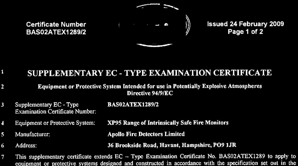
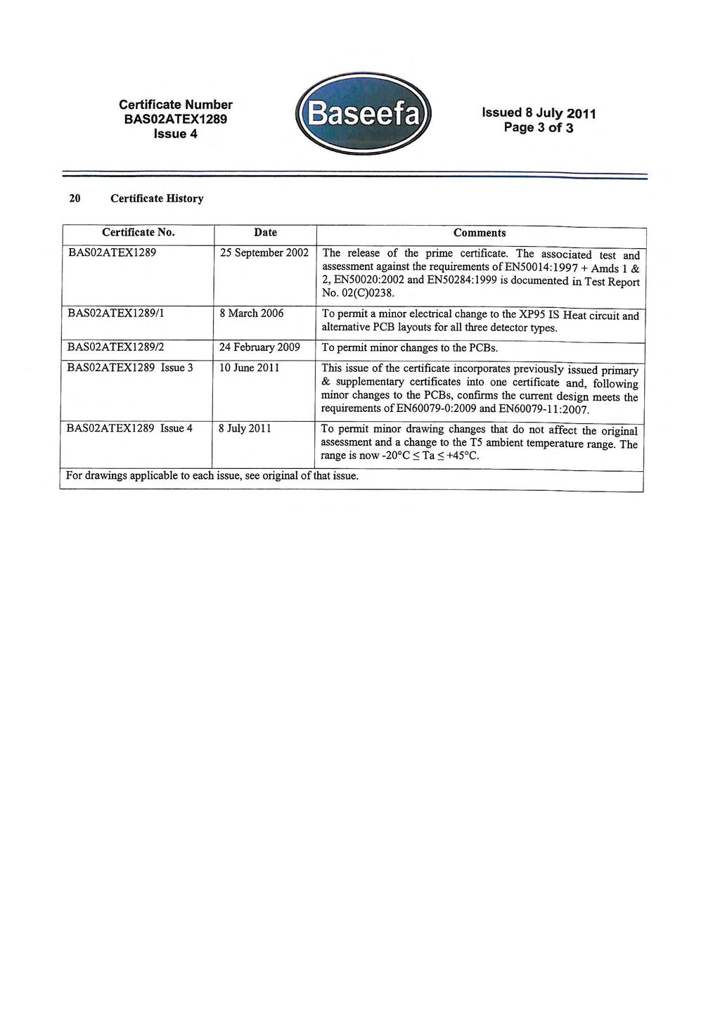
5 safetec 2.2 System Analysis The system comprises only approved or analyzed devices. The system comprises only one linear power source. Step Item Interface Smoke Detector System a) Explosion Group IIC IIC IIC b) Protection Level ia ia ia c) Temperature Class Not applicable T5 T5 d) Environment temperature -20 C +60 C -20 C +45 C (T5) e) Comparison of nominal values See below (Analysis of intrinsical safety of electric circuit(s) in detection unit(s)) f) Cable values g) Isolation against earth isolated isolated isolated ok Analysis of intrinsical safety of electrical circuit(s) in detection unit(s) No. Descript ion 1 Galvanic Isolator 2 Galvanic Isolator Associated Electrical Apparatus Typ KFD0-CS- Ex1.54 (1 channel) KFD0-CS- Ex2.54 ( 2 chan., values per channel) Maker Pepperl + Fuchs Pepperl + Fuchs EC-Type Examination Certificate BAS00ATE X7087 BAS00ATE X7087 U 0 [V] I 0 [ma] P 0 [mw] L 0 [mh] C 0 [nf] Ex- Gruppe ,3 77 IIC ,3 77 IIC No. Intrinsically Safe Apparatus Descript ion 1 Smoke Detector 2 Pressure Switch 3 Resistor R1 Typ Maker EC-Type Examination Certificate XP95 I.S Apollo BAS02ATE X1289, BAS02ATE X1289/1 U i [V] I i [ma] P i [mw] L i [mh] C i [nf] Ex- Gruppe IIC Huba AC03 1KΏ Philips Art.No.: DOK File: DOK odt Rev.0 5
6 safetec 4 Resistor R2 5 Cable A, Cable B MBE KΏ FMKHC 2x2x0,75 Beyschla g Nexans L c = 0,7mH/km C c = 60nF/km l = 100m 0, Conditions check for intrinsic safety: U0 <= Ui 28V <= 28V I0 <= Ii 93mA <= 93,3mA P0 <= Pi 653mW <= 670mW L0 >= Li 4,3mH >= 0,07mH C0 >= Ci 77nF >= 6nF Result: conditions for intrinsic safety are fulfilled. Art.No.: DOK File: DOK odt Rev.0 6
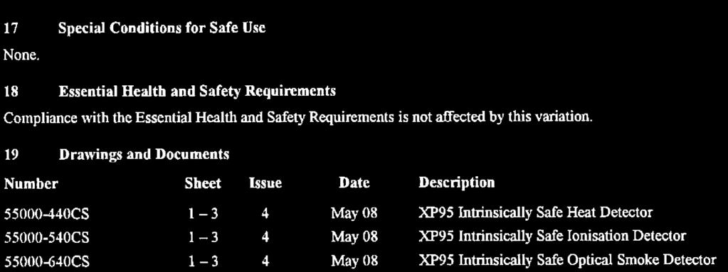
7 safetec Max. Temperature Rise in Resistors under Fault Conditions The resistors, which are integrated into the circuit, are simple apparatus according IEC clause 5.7. They do not add any capacitors or inductances. The resistors are small parts with a surface area smaller than 1000 mm², which allows a maximum temperature of 150 C for T5 (IEC :2007 clause 5.6.2). R1: Resistor 1K Ω surface area: ~ 275 mm² (< 1000 mm²) rated power dissipation: 3 W max. power supply from isolator: 0,653 W temperature rise at 1W power dissipation: 120 K (see datasheet) temperature rise at 0,653 W: 78,4 K max. environment temperature: 45 C max. temperature rise at 0,653 W: 123,4 C (< 150 C) R2: Resistor 22KΩ surface area: rated power dissipation: max. power dissipation: thermal resistance temperature rise at 0,036 W: < 1000 mm² 1 W 28V*28V/22KΩ= 0,036 W 108 K/W ~4 K 3 Fan Unit SDS-M0440 / SDS-M0441 The fan unit SDS-M0440/SDS-M0441 is protected by method c (constructional safety). See separate documentation Technical Documentation DOK Art.No.: DOK File: DOK odt Rev.0 7
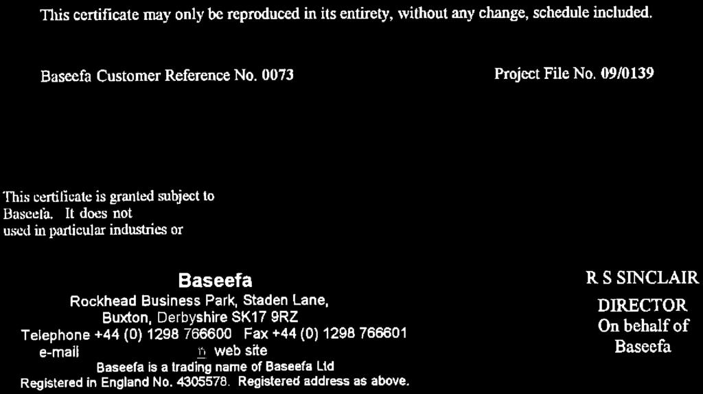
8 safetec 4 Attached Documents 4.1 Drawings No. Document Pages SDS48-Ex-1.tcd Block Diagram SDS-48 with Earth Connections 1 SDS48-Ex-2.tcd Connection Diagram SDS-48 Smoke Detection Panel and Extension Unit(s) Certificates of Conformity No. Certificate for... Pages BAS02ATEX1289 Smoke Detector XP95 I.S Type BAS02ATEX1289/1 2 BAS02ATEX1289/2 2 BAS02ATEX1289 Issue 3 3 BAS02ATEX1289 Issue 4 3 BAS00ATEX7087 Galvanic Isolator 5 BAS00ATEX7087/1 KFD0-CS-Ex1.54 and KFD0-CS-Ex BAS00ATEX7087/2 2 BAS00ATEX7087/3 2 BAS00ATEX7087/4 3 BAS00ATEX7087/5 4 Sign Datum: :02 Uhr Dipl. Ing. (FH) Klaus Brandes safetec Brandes und Niehoff GmbH Art.No.: DOK File: DOK odt Rev.0 8
9 Ausgabe: to Cargo Holds Way-Valve, Connection to CO2-manifold 2 Hose, 13/20mm 3 Smoke Detection Oanel, compound of: 1 or 2 Detection Units (upper) and 1 Evaluation Unit 4 Extension Panel, compound of: 1 or 2 Detection Units 5 Repeater Panel (not exposed to hazardous area) 6 Steel Pipe 7 Fan Unit SDS-M0440 or SDS-M0441 Earth connection safetec Rev. 2 Gepr HZ kb kb Bearb Block Diagram Smoke Detection System SDS-48 with Earth Connections Application: Smoke Det. System: SDS-48 Zeichnung / Drawing: SDS48-Ex-1.tcd Seite / Page:
10 Ausgabe: Evaluation Unit (Part of Smoke Detection Panel) Power Supply Module BG Galvanic Isolators with channels, compound of: KFD0-CS-Ex1.54 or KFD0-CS-Ex2.54 (1 or 2 channels each) single Channel 1 wires (<1m) Intrinsically Safe Circuits Detection Unit (Part of Smoke Detection Panel or Extension Panel Smoke Detector XP95 I.S. Pressure Switch Type 605 P L1+ L2-1 3 max. 8 pairs of smoke detectors and pressure switches Detector Connection Module BG02.810, BG02.819, BG02.820, BG02.819, BG02.840, BG02.849, Smoke Detector XP95 I.S. Pressure Switch Type 605 P L1+ L Channel internal wiring Loop A + - Loop B + - R1 R1 **) R2 Loop B + - Channel Channel Cable A to Extension Panel 1 *) internal wiring (intrinsically safe circuit) 2nd Detection Unit (Part of Smoke Detection Panel or Extension PanelSDS-12, SDS-E12, SDS-E16 and SDS-EC16 only) Smoke Detector XP95 I.S. Pressure Switch Type 605 P max. 8 pairs of smoke detectors and pressure switches Smoke Detector XP95 I.S. Pressure Switch Type 605 P Channel 1 L1+ L2-1 3 Detector Connection Module BG02.810, BG02.819, BG02.820, BG02.819, BG02.840, BG02.849, L1+ L Channel Cable B to Extension Panel 2 *) Loop A + - Loop B + - R1 R1 **) R2 Loop B + - *) Detection units of extension panels: see detection units of smoke detection panel! safe area hazardous area **) R2 mounted only on BG and BG safetec Rev. 0 Gepr kb kb kb Bearb Connection Diagram SDS-48 Smoke Detection Panel (SDS-0, SDS-4, SDS-8, SDS-12) and Extension Unit(s) (E-4, E-8, E-12, E-16, EC-16) Application: Smoke Det. System: SDS-48 Zeichnung / Drawing: SDS48-Ex-2.tcd Seite / Page: 1
11
12
13
14
15


16
17
18
19
20
21
22
23
24
25
26
27
28
29
30
31
32
33
34
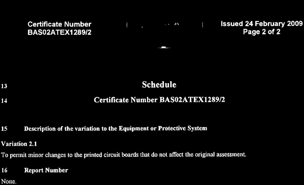
35 Certificate Number BAS00ATEX7087/4 Issued 10 September 2008 Page 2 of 3 13 Schedule 14 Certificate Number BAS00ATEX7087/4 15 Description of the variation to the Equipment or Protective System Variation 4.1 i) To permit minor drawing changes, minor PCB layout changes and the addition of the certification code [Ex iad]. ii) Addition of two new models: KFD0-CS-Ex1.54 with part number Y KFD0-CS-Ex2.54 with part number Y iii) To confirm that the current designs meet the requirements of EN :2006, EN :2007, EN :2004 and EN : Report Number GB/BAS/ExTR /00 17 Special Conditions for Safe Use None 18 Essential Health and Safety Requirements Compliance with the Essential Health and Safety Requirements is not affected by this variation. 19 Drawings and Documents Number Sheet Issue Date Description * C 1 of 1 C Circuit Diagram (ref) for Smart Fire Detector Isolator Type K*D0-CS- Ex1.54 & 2.54(-Y72221&2) * H 1 7 H Parts List for Smart Fire Detector Isolator Type KHD0-CS-Ex2.54 and KFD0-CS-Ex2.54(-Y72222) * B 1 of 1 B Parts List for T1/. Transformer Mounting Board for K*D0-CS- Ex1.54(-Y72221) and K*D0-CS-Ex2.54(Y-72222) * H 1 5 H Parts List for Smart Fire Detector Isolator Type KHD0-CS-Ex1.54 and KFD0-CS-Ex1.54(-Y72221) * A 1 of 1 A Component Overlay (ref) for Smart Fire Detector Isolator Type K*D0- CS-Ex1.54 & 2.54(-Y72221&2) * A 1 of 1 A Plastic Moulding Details for Toroidal Transformers for Galvanic Isolators G 1 & 2 G G.A. for 20mm Non-Power Rail FIM Housing * B 1 of 1 B Cutting/Drilling Details for Barrier Zener Mounting Board * C 1 & 2 C P.C.B. Master for (Mk.5) Transformer Mounting Board [K and E System] * F 1 3 F P.C.B. Master for Smart Fire Detector Isolator K*D0-CS-Ex1.54 & 2.54(-Y72221&2)
 and K*D0-CS-Ex2.54(-Y72222) *256-0120A 1 of 1 A 11.02.00 Winding Details for Transformer. 50 Turns Bifilar P1 & P2. 50 Turns Bifilar S1 & S2. *257-0208C 1 & 2 C 21.03.")
36 Certificate Number BAS00ATEX7087/4 Issued 10 September 2008 Page 3 of 3 Number Sheet Issue Date Description * C 1 of 1 C Connection Details for Transformer T1/. For K*D0-CS-Ex1.54(- Y72221) and K*D0-CS-Ex2.54(-Y72222) * A 1 of 1 A Winding Details for Transformer. 50 Turns Bifilar P1 & P2. 50 Turns Bifilar S1 & S2. * C 1 & 2 C PCB Lacquering Details for Smart Fire Detector Isolator Type K*D0-CS-Ex2.54(-Y72222) * D 1 & 2 D PCB Lacquering Details for Smart Fire Detector Isolator Type K*D0-CS-Ex1.54(-Y72221) BS-10 1 & Type Label ATEX. KFD0-CS-Exx.54 *These drawings are common to, and held with, IECEx BAS
37
38
39
40
IECEx Certificate of Conformity
 INTERNATIONAL ELECTROTECHNICAL COMMISSION IEC Certification Scheme for Explosive Atmospheres for rules and details of the IECEx Scheme visit www.iecex.com Certificate No. : Status: Date of Issue: Applicant:
Declaration of conformity
 File: ATEX Manoswitch DoC 2017-10-20 Rev: 2017-10-20 id: mk Declaration of conformity The products listed in Appendix B, meet the requirements for a simple apparatus given by the standards listed below.
Technical Data. General specifications Switching element function Rated operating distance s n 5 mm
 0102 Model Number Features 5 mm flush Usable up to SIL 3 acc. to IEC 61508 Application Danger! In safety-related applications the sensor must be operated with a qualified fail safe interface from Pepperl+Fuchs,
OilSET Installation and Operating Instructions. Oil Separator Alarm Device with SET/DM3AL sensor
 Labkotec UK Ltd Adminicle House 1 Lumb Lane Audenshaw Manchester M34 5WH GREAT BRITAIN Tel: 0844 3350 477 Fax: 0161 4281 179 E-mail: info@labkotec.co.uk 10.8.2012 Internet: www.labkotec.co.uk 1/13 OilSET-1000
SET Installation and Operating Instructions. Level switch for one sensor
 Labkotec Oy Myllyhaantie 6 FI-33960 PIRKKALA FINLAND Tel.: +358 29 006 260 Fax: +358 29 006 1260 7.11.2013 Internet: www.labkotec.fi 1/14 SET-1000 Level switch for one sensor Copyright 2013 Labkotec Oy
Inductive slot sensor
 0102 Model Number Features 2 mm slot width Technical Data specifications Switching function Normally closed (NC) Output type NAMUR Slot width 2 mm Depth of immersion (lateral) 5... 7 mm, typ. 6 mm Output
Technical Data. Dimensions
 0102 Model Number Features 8 mm non-flush Stainless steel housing Usable up to SIL2 acc. to IEC 61508 Technical Data specifications Switching element function NAMUR, NC Rated operating distance s n 8 mm
Technical Data. General specifications Switching element function Rated operating distance s n 5 mm
 0102 Model Number Features 5 mm non-flush Usable up to SIL2 acc. to IEC 61508 Technical Data specifications Switching element function NAMUR, NC Rated operating distance s n 5 mm Installation non-flush
Intrinsically Safe Flame Detector Installation Guide
 This document is IS Installation Guide/00/Issue 3 Intrinsically Safe Installation Guide General This Installation Guide gives information on the intrinsically safe (I.S.) version of the flame detectors
Technical Data. General specifications Switching element function Rated operating distance s n 8 mm
 0102 Model Number Features 8 mm non-flush Usable up to SIL 3 acc. to IEC 61508 Application Danger! In safety-related applications the sensor must be operated with a qualified fail safe interface from Pepperl+Fuchs,
Intrinsically Safe Solutions
 Intrinsically Safe Solutions INSTALLATION MANUAL 04/12/14 Rev D DOC-01-029 Documentation Feedback Your feedback helps us keep our documentation up to date and accurate. If you have any comments or suggestions
Technical Data. Dimensions
 0102 Model Number Features 5 mm flush Usable up to SIL2 acc. to IEC 61508 Accessories EXG-18 Quick mounting bracket with dead stop BF 18 Mounting flange, 18 mm Technical Data specifications Switching element
4) Intrinsic Safety Certification
 Intrinsic Safety Certification") INSTRUCTION MANUAL Minialert Intrinsically Safe Round Combined Unit Section Volume Control Tone Generator S2 S3 Tone Selection Switches Fig 1 Simplified block diagram The combined unit is CE marked for
INSTRUCTION MANUAL Minialert Intrinsically Safe Round Combined Unit Section Volume Control Tone Generator S2 S3 Tone Selection Switches Fig 1 Simplified block diagram The combined unit is CE marked for
DB5 Intrinsically Safe Sounder Type DB-5
 Operating Instructions RTK Instruments Limited DB5 Intrinsically Safe Sounder Type DB-5 Description The DB5 Sounder is a strong, lightweight warning sounder, CENELEC certified to Ex II 1G EExia IIC T4
Physikalisch-Technische Bundesanstalt
 (1) EC-TYPE-EXAMINATION CERTIFICATE (Translation) (2) Equipment and Protective Systems intended for Use in Potentially Explosive Atmospheres Directive 94/9/EG (3) EC-type-examination Certificate Number:
Technical Data. General specifications Switching element function Rated operating distance s n 4 mm
 0102 Model Number Features 4 mm non-flush Accessories BF 12 Mounting flange, 12 mm Technical Data specifications Switching element function NAMUR, NO Rated operating distance s n 4 mm Installation non-flush
Technical Data. Dimensions
 0102 Model Number Features Comfort series 50 mm non-flush Technical Data specifications Switching element function NAMUR, NC Rated operating distance s n 50 mm Installation non-flush Output polarity NAMUR
IECEx Certificate. INTERNATIONAL ELECTROTECHNICAL COMMISSION IEC Certification Scheme for Explosive Atmospheres
 INTERNATIONAL ELECTROTECHNICAL COMMISSION IEC Certification Scheme for Explosive Atmospheres for rules and details of the IECEx Scheme visit www.iecex.com Certificate No.: Certificate history: Status:
Technical Data. Dimensions
 0102 Model Number Features 15 mm non-flush Technical Data specifications Switching element function NAMUR, NC Rated operating distance s n 15 mm Installation non-flush Assured operating distance s a 0...
Annubar Flowmeter Series
 Reference Manual Appendix B Approvals Annubar Flowmeter Series Hazardous Locations Installations.................. page B-1 Rosemount 3051SFA Product Certifications.......... page B-1 Rosemount 3095MFA
Technical Data. General specifications. Rated operating distance s n 5 mm
 0102 Model Number Features 5 mm non-flush Usable up to SIL 2 acc. to IEC 61508 Technical Data specifications Switching function Normally closed (NC) Output type NAMUR Rated operating distance s n 5 mm
PEPPERL+FUCHS GmbH
 Comfort series 1.5 mm embeddable M8x1 4 25 16 13 LED Switching element function NAMUR NC Rated operating distance s n 1,5 mm Installation embeddable Assured operating distance s a 0... 1,215 mm Reduction
SET-2000 Oil/Sludge 12 VDC
 Labkotec Oy Myllyhaantie 6 FI-33960 PIRKKALA FINLAND Tel: + 358 29 006 260 Fax: + 358 29 006 1260 12.2.2015 Internet: www.labkotec.fi 1/14 SET-2000 Oil/Sludge 12 VDC Alarm Device for Oil Separators with
INSTRUCTION MANUAL IS-mB1 Minialite Intrinsically Safe Round LED Beacon
 INSTRUCTION MANUAL Minialite Intrinsically Safe Round LED This instruction sheet describes installations which conform to EN60079:Part14:2008 Electrical Installation in Hazardous Areas. When designing
Technical Data. General specifications Switching element function DC Dual NC Rated operating distance s n 3 mm
 0102 Model Number Features Direct mounting on standard actuators EC-Type Examination Certificate TÜV99 ATEX 1479X Accessories BT32 BT32XS BT32XAS BT33 BT34 V1-G-N4-5M-PUR Female cordset, M12, 4-pin, NAMUR,
IECEx Certificate of Conformity
 Page 1 of 5 INTERNATIONAL ELECTROTECHNICAL COMMISSION IEC Certification Scheme for Explosive Atmospheres for rules and details of the IECEx Scheme visit www.iecex.com issue No.:1 Status: Current Certificate
OilSET Installation and Operating Instructions. Oil Separator Alarm Device
 Labkotec Oy Myllyhaantie 6 FI-33960 PIRKKALA FINLAND Tel: +358 29 006 260 Fax: +358 29 006 1260 18.11.2010 Internet: www.labkotec.fi 1/10 OilSET-1000 Oil Separator Alarm Device Copyright 2010 Labkotec
E2S Datasheet v10a. The IS-mA1 is suitable for all intrinsically safe signalling applications including fire, security and process control.
 E2S Datasheet 1.2.1 v10a ISmA1 ISminialarm The ISmA1 is a compact, 100dB(A) alarm sounder. Approvals include ATEX, IECEx and GOSTR for Zone 0 applications and FM approval for Class I Division 1 and Class
PROZESSAUTOMATION. Manual SEGMENT PROTECTOR R-SP-!12. Zone 1 Zone 2 / Div 2 FNICO
 PROZESSAUTOMATION Manual SEGMENT PROTECTOR R-SP-!12 FieldConnex TM Segment Protectors with overloaod protection and short-circuit current limitation for the connection of 12 field devices Zone 1 Zone 2
A Characteristics for Electrical Equipment integrated Into SLR Enclosure - Intrinsically Safe Reference Document
 A190325 Characteristics for Electrical Equipment integrated Into SLR Enclosure - Intrinsically Safe Reference Document CONTENTS INTRODUCTION 1. DUAL CERTIFIED COMPONENTS 1.1 Simple Apparatus Switches For
IECEx Certificate of Conform ity
 IECEx Certificate of Conform ity INTERNATIONAL ELECTROTECHNICAL COMMISSION IEC Certification Scheme for Explosive Atmospheres for rules and details of the IECEx Scheme visit www.iecex.com Certificate No.:
E2S Datasheet v10a
 E2S Datasheet 1.2.3 v10a ISmC1 ISminialert The ISmC1 is a compact combined 100dB(A) alarm sounder and L.E.D. beacon only one Zener barrier or galvanic isolator required to run both sounder & beacon or
INSTRUCTION MANUAL (ATEX)
") INSTRUCTION MANUAL (ATEX) ISmA1M Minialarm Intrinsically Safe Round ISmA1M Volume Control Tone Generator S3 Tone Selection Switches Fig 1 Simplified block diagram The ISmA1M sounder is CE marked for compliance
INSTRUCTION MANUAL (ATEX) ISmA1M Minialarm Intrinsically Safe Round ISmA1M Volume Control Tone Generator S3 Tone Selection Switches Fig 1 Simplified block diagram The ISmA1M sounder is CE marked for compliance
EU DECLARATION OF CONFORMITY
 The Low Voltage Directive (LVD) 2014/35/EU and Electromagnetic Compatibility (EMC) Directive 2014/30/EU. Capacitive level sensor DLS 27N(T) Capacitive level sensor type DLS 27N(T) is designed to bistable
PROTECT SRB 200EXi-1A
 2 Installation up to zone 1/21 J S L1 0V X1 X3 S11 S12 S21 S22 Installation up to zone 2 A1 F1 F2 U B U EXi U i 0V S12 S22 X1 X3 K1 Logic K2 K1 K2 13 23 U EXi SRB 200EXi U B -1A U i K1 K2 PA PA A1 A2 13
Safety instructions VEGADIF DF65.GX*****H/Z/P/F***** IECEx BVS
 Safety instructions VEGADIF DF65.GX*****H/Z/P/F***** IECEx BVS 10.0008 Ex td A20, A20/21, A20/22, A21 IP66 T 0044 37675 Contents 1 Area of applicability 3 2 General information 3 2.1 Zone 20 instruments
INSTRUCTION MANUAL. SIL 3 - SIL 2 IIB Group Power Supply for Hazardous Area Equipment DIN-Rail Model PSD1001C PSD1001C
 PSD1001C INSTRUCTION MANUAL SIL 3 SIL 2 IIB Group Power Supply for Hazardous Area Equipment DINRail Model PSD1001C PSD1001C SIL 3 SIL 2 IIB Group Power Supply for hazardous Area Equipment ISM006510 General
D SYSTEM CONTROL DWG. APPROVED BY. OrCAD 6 ROSEMOUNT 2410
 FIELDBUS INTRINSICALLY SAFE CONCEPT (FISCO) APPROVAL FISCO allows interconnection of intrinsically safe apparatus to associated apparatus not specially examined in such combination. The criteria for interconnection
AND INSTALLATION MANUAL
 Labkotec Oy Myllyhaantie 6 FI-33960 PIRKKALA FINLAND Tel. +358 29 006 260 Fax +358 29 006 1260 Internet: www.labkotec.fi 10.10.2013 SET/DM3AL Level sensor OPERATION AND INSTALLATION MANUAL 1(5) SYMBOLS
BA334D Intrinsically safe Externally powered pulse input field mounting rate totaliser Issue 13
 TR Automatyka Sp. z o. o. Tel. (+48 022) 886 10 16 www.trautomatyka.pl ul. Lechicka 14 ; 02-156 Warszawa Fax. (+48 022) 846 50 37 biuro@trautomatyka.pl BA334D Intrinsically safe Externally powered pulse
SITRANS T. SITRANS T Explosion protected temperature sensor. General information. Marking of the degree of protection. Range of uses.
 General information 1 Marking of the degree of protection 2 SITRANS T SITRANS T Explosion protected temperature sensor Operating Instructions Range of uses 3 Installation 4 Assembly and disassembly 5 Commissioning
Manual Power relay SR853
 Manual Power relay SR853 Product types SR853.8.x.x, Rev. 1 SR853 manual page2 The symbols WARNING, CAUTION, NOTE This symbol warns of a serious hazard. Failure to observe this warning may result in death
OPTIBAR DP 7060 Supplementary Instructions
 OPTIBAR DP 7060 Supplementary Instructions Differential pressure transmitter Category ATEX II 1/2G, 2G Ex db ia IIC T6...T1 Ga/Gb, Gb IECEx Ex db ia IIC T6...T1 Ga/Gb, Gb Housing Aluminium: Single chamber,
IECEx Certificate of Conformity
 Page 1 of 10 IECEx Certificate of Conformity INTERNATIONAL ELECTROTECHNICAL COMMISSION IEC Certification Scheme for Explosive Atmospheres for rules and details of the IECEx Scheme visit www.iecex.com Certificate
DICTATOR Hold-Open Systems for Hazardous Areas
 DICTATOR for Hazardous Areas Products to be used in hazardous areas obviously have to meet special demands. The European ATEX directives (first the EN 94/9/EG and then the directive 2014/34/ EU) brought
Air Sensor. SAC Ex FCS Ex. Manual ATEX. AQ M-Tech AB
 Air Sensor SAC Ex FCS Ex Manual AQ M-Tech AB ATEX Air Sensor SAC Ex FCS Ex ATEX Certified AQ M-Tech AB Manual version 2.2 February 2017 2 Air Sensor Manual for SAC Ex and FCS Ex Table of contents 1. Manufacturer
Orbis IS Product Guide MAN 3041
 Orbis IS Product Guide MAN 3041 TABLE OF CONTENTS Page No. 1 Introduction to Intrinsic Safety... 2 2 Range of Products... 3 3 Features of Orbis IS... 3 4 Choosing a Detector: Q & A... 3 5 Orbis IS Optical
OPTIBAR P 1010/2010 C Supplementary instructions
 OPTIBAR P 1010/2010 C Supplementary instructions Pressure transmitter Equipment category II 1G / Ga, II 1D / Da in protection type intrinsic safety Exi KROHNE CONTENTS OPTIBAR P 1010/2010 C 1 Safety instructions
Additional Operating Instructions SITRANS F. Vortex flowmeters. SITRANS FX330 Ex-i.
 Additional Operating Instructions SITRANS F Vortex flowmeters Ex-i Edition 09/2018 CONTENTS 1 Safety instructions 3 1.1 General notes... 3 1.2 EU conformity... 3 1.3 Approval according to the IECEx scheme...
BA338C Intrinsically safe Externally powered pulse input panel mounting rate totaliser issue 13
 BA338C Intrinsically safe Externally powered pulse input panel mounting rate totaliser issue 13 Certification information label Total display Rate display Rotating flow indicator Annunciators for optional
FDOOT241-A9-Ex Multisensor fire detector
 FDOOT241-A9-Ex Multisensor fire detector ASAtechnology TM For potentially explosive areas Sinteso Collective Signal processing with ASAtechnology Multiple protocol detector (collective/fdnet-ex) Event-controlled
Safety instructions VEGADIS DIS61.CC/O** VEGADIS DIS81.CC/O******
 Safety instructions VEGADIS DIS61.CC/O** VEGADIS DIS81.CC/O****** CSA 14.2662675 Ex ia IIC T6 Ga, Gb 0044 Document ID: 48924 Contents 1 Area of applicability... 3 2 General information... 3 3 Technical
FDCL221-Ex Line adapter (Ex)
") FDCL221-Ex Line adapter (Ex) Addressed (FDnet-Ex/C-NET-Ex) For operating FDnet-Ex/C-NET-Ex peripheral devices in potentially explosive areas Sinteso Cerberus PRO Electrical isolation of Ex and non-ex lines
FDCL221-Ex Line adapter (Ex) Addressed (FDnet-Ex/C-NET-Ex) For operating FDnet-Ex/C-NET-Ex peripheral devices in potentially explosive areas Sinteso Cerberus PRO Electrical isolation of Ex and non-ex lines
IECEx Certificate of Conformity
 IECEx Certificate of Conformity INTERNATIONAL ELECTROTECHNICAL COMMISSION IEC Certification Scheme for Explosive Atmospheres for rules and details of the IECEx Scheme visit www.iecex.com Certificate No.:
SET-2000 Hi Level/Oil
 Labkotec Oy Labkotie 1 FI-36240 KANGASALA FINLAND Tel: + 358 29 006 260 Fax: + 358 29 006 1260 13.03.2008 Internet: www.labkotec.fi Alarm Device for Oil Separators Copyright 2008 Labkotec Oy We reserve
OilSET-1000 (12 VDC)
") Labkotec Oy Myllyhaantie 6 FI-33960 PIRKKALA FINLAND Tel: +358 29 006 260 Fax: +358 29 006 1260 Internet: www.labkotec.fi 20.03.2009 1/11 OilSET-1000 (12 VDC) Oil Separator Alarm Device Copyright 2009
Labkotec Oy Myllyhaantie 6 FI-33960 PIRKKALA FINLAND Tel: +358 29 006 260 Fax: +358 29 006 1260 Internet: www.labkotec.fi 20.03.2009 1/11 OilSET-1000 (12 VDC) Oil Separator Alarm Device Copyright 2009
Installation and Operating Instruction
 Installation and Operating Instruction Automatic Fire Detectors Series 900 Ex (i) 9893 0.00 GB Technical changes reserved! 0 Installation and Operating Instruction Automatic Fire Detectors Series 900 Ex
Instrumentation Products and Applications
 1 1/0 Instrumentation Products and Applications 1 Instrumentation Safety barriers I.S. Isolators - DIN rail mounting - Eurocards - Modules Remote I/O Operating and monitoring systems Instrumentation systems
Operating Manual MS220KA and MSR220KA
 Temperature Relays and MINIKA, Mains Monitoring, Digital Panel meters MINIPAN, Switching Relays and Controls Operating Manual MS220KA and MSR220KA ZIEHL industrie elektronik GmbH + Co KG Daimlerstraße
Fire Alarm System Accessories
 Approved by APPROVED Fire Alarm System Accessories FM Approved* Intrinsically Safe Devices Single and Dual Channel Isolated Barrier Modules Features Single or dual channel intrinsically safe, transformer
SBEx-4 BISTATE SEPARATOR 1, 2, 3 or 4 channels in rail housing (TS35, 22,5mm width)
") SBEx-4 BISTATE SEPARATOR,, 3 or 4 channels in rail housing (TS3,,mm width) - group I category (M), group II and III category () accompanying device, - intrinsically safe input circuits with ia protection
SBEx-4 BISTATE SEPARATOR,, 3 or 4 channels in rail housing (TS3,,mm width) - group I category (M), group II and III category () accompanying device, - intrinsically safe input circuits with ia protection
DSF xx10.xx xhv Ex-Atex Hall Effect Single Channel Speed Sensor
 Product ID Type # Product # Drawing # DSF 1210.00 SHV Ex-atex (2m) 374Z-05066 110428F1 DSF 1210.00 SHV Ex-atex (5m) 374Z-05176 110428F1 DSF 1210.00 SHV Ex-atex (10m) 374Z-05590 110428F1 DSF 1410.00 SHV
Tank Gauging System Special Safety Instruction
 Tank Gauging System www.rosemount-tg.com Rosemount TankRadar REX Table of Contents Contents SPECIAL SAFETY INSTRUCTION........................ 1-1 1. GENERAL REQUIREMENTS....................... 1-2 1.1
Operating Manual MS220DA
 ZIEHL industrie elektronik GmbH + Co KG Daimlerstraße 13, D 74523 Schwäbisch Hall + 49 791 504-0, info@ziehl.de, www.ziehl.de Temperature Relays and MINIKA Mains Monitoring Digital Panel Meters MINIPAN
Connection. e. g. Pt100. reference limit. yellow Output I. Composition
 Trip amplifiers for Pt1, Ni1 KFD2GREx1 Connection e. g. Pt1 Input EEx ia IIC 1+ 2 3 Hazardous area 1channel Input EEx ia IIC 2 switching points operate on 2 output relays High/low alarm can be selected
PESO. Temperature sensors with cables Thermocouples and RTD temperature probes ATEX I, e, t For use in areas with an explosion hazard
 Temperature sensors with cables Thermocouples and RTD temperature probes ATEX I, e, t For use in areas with an explosion hazard Persons concerned: Experienced professional electricians as per EU Directive
Assembly. Host Sub-D Alarm
 HighDensity Power Hub, Generic Interface Features Assembly 4 segments, loadsharing redundancy Output: 22... 24 V/360 ma, Ex ib IIC for intrinsically safe, highpower segments Redundant connection to PROFIBUS
ExDetector HC-100. Data Sheet. Gas Measuring and Alarm Systems
 HC-100 Gas Measuring and Alarm Systems HC-100 Application / Construction The HC100 series of measuring probes, used in conjunction with evaluation systems, have the following functions: Measurement and
Survey of electrical equipment installed in hazardous areas on tankers
 (June 2015) Survey of electrical equipment installed in hazardous areas on tankers 1. Application The recommendations in this document apply for survey of electrical installation in hazardous areas on
XP95 Intrinsically Safe Product Guide MAN 3054
 XP95 Intrinsically Safe Product Guide MAN 3054 TABLE OF CONTENTS. Page No. 1 Introduction to Intrinsically Safe... 1 2 Classification of Hazardous Areas... 1 3 XP95 I.S. Ionisation Smoke Detector... 3
SENSOR O2 O2-A
 Item Inquiry Vian code Description QNY Manufacturer 1 7 10359 disposable O sensor SPXCDXSO1SS senspoint XCD 6 honeywell 104 136540 Sensor Gas,Gasmonitor 0-5 No:09737 1 Bieler+Lang 1 104 136543 SENSOR O
VERSAFLOW VORTEX Supplementary instructions
 VERSAFLOW VORTEX Supplementary instructions Vortex flowmeter Equipment category II 2G CONTENTS VERSAFLOW VORTEX 1 Safety instructions 3 1.1 General notes... 3 1.2 EC conformity... 3 1.3 Approval according
Continuous Gas Analyzers AO2000 Series AO2040-CU Ex Central Unit in Category 2G. Operator s Manual 42/24-13 EN Rev. 3
 Continuous Gas Analyzers AO2000 Series AO2040-CU Ex Central Unit in Category 2G Operator s Manual 42/24-13 EN Rev. 3 Table of Contents Page Preface 3 General Safety Information 4 Special Safety Instructions
IECEx Certificate of Conformity
 IECEx Certificate of Conformity INTERNATIONAL ELECTROTECHNICAL COMMISSION IEC Certification Scheme for Explosive Atmospheres for rules and details of the IECEx Scheme visit www.iecex.com Certificate IECEx
ATEX Installation Instructions for Micro Motion F-Series Sensors with Certificate DMT 01 ATEX E 158 X
 Installation Instructions P/N MMI-20010174, Rev. A June 2007 ATEX Installation Instructions for Micro Motion F-Series Sensors with Certificate DMT 01 ATEX E 158 X For ATEX-approved sensor installations
FAHM Co. Temperature Transmitter PTT74 Series
 FAHM Co. PTT74 Series The PTT74 is a versatile temperature transmitter that delivers field reliability and advanced accuracy and stability to meet demanding process needs. PTT74 Family of Transmitters
OOH740-A9-Ex Multi-sensor fire detector
 OOH740-A9-Ex Multi-sensor fire detector ASAtechnology TM For potentially explosive areas Cerberus PRO Collective Signal processing with ASAtechnology Multiple protocol detector (collective/c-net-ex) Event-controlled
国家级仪器仪表防爆安全监督检验站 National Supervision and Inspection Centre for Explosion Protection and Safety of Instrumentation (GYJ ) (Attachment Ⅰ) Attachm
 (Attachment Ⅰ) Attachm") 国家级仪器仪表防爆安全监督检验站 National Supervision and Inspection Centre for Explosion Protection and Safety of Instrumentation (GYJ14.1317) (Attachment Ⅰ) Attachment Ⅰ (Translation) Isolated safety barrier type KFa
国家级仪器仪表防爆安全监督检验站 National Supervision and Inspection Centre for Explosion Protection and Safety of Instrumentation (GYJ14.1317) (Attachment Ⅰ) Attachment Ⅰ (Translation) Isolated safety barrier type KFa
Local Control Panels for VG9000H LCP9H Series. Installation, Maintenance and Operating Instructions
 Local Control Panels for VG9000H LCP9H Series Installation, Maintenance and Operating Instructions 7 LCP9H 70 en 9/2011 2 7 LCP9H 70 en Table of Contents 1 LCP9H Local Control Panels for VG9000H.. 3 1.1
User s Manual YTA610 and YTA710 NEPSI Certification
 User s Manual YTA60 and YTA70 NEPSI Certification [Option code: /NS, /NS5 and /NF] st Edition . INTRODUCTION Thank you for purchasing the YTA60 and YTA70 Temperature transmitters. This manual contains
OOH740-A9-Ex Multisensor fire detector
 OOH740-A9-Ex Multisensor fire detector ASAtechnology TM For potentially explosive areas Cerberus PRO Collective Signal processing with ASAtechnology Multiple protocol detector (collective/c-net-ex) Event-controlled
Crowcon Gasmaster. 1 to 4 channel gas detection control panel. Installation, Operation and Maintenance Manual
 1 to 4 channel gas detection control panel Installation, Operation and Maintenance Manual M070010 Issue 2 October 2014 The equipment described in this manual may have mains voltages applied to it. Ensure
Manual Isolating Barrier D461R1 (Revision 01)
") D461R1 Manual Isolating Barrier D461R1 (Revision 01) Product Manual Original Instructions valid for models D461R1.11 with 1x signal input into 1x isolated signal output D461R1.12 with 1x signal input into
D461R1 Manual Isolating Barrier D461R1 (Revision 01) Product Manual Original Instructions valid for models D461R1.11 with 1x signal input into 1x isolated signal output D461R1.12 with 1x signal input into
Easidew PRO I.S. Process Dewpoint Transmitter User s Manual
 Easidew PRO I.S. Process Dewpoint Transmitter User s Manual KAHN INSTRUMENTS, INC. 885 Wells Road, Wethersfield, CT 06109 Phone: 860-529-8643 Fax: 860-529-1895 E-mail: info@kahn.com www.kahn.com Inside
USER GUIDE FOR GASSONIC SURVEYOR ULTRASONIC GAS LEAK DETECTOR
 T E C H N I C A L D O C U M E N T A T I O N USER GUIDE FOR GASSONIC SURVEYOR ULTRASONIC GAS LEAK DETECTOR CONTENTS 1.0 The Gassonic Surveyor....................................... 3 1.1 Application..............................................
Ex Long & Short stroke LPI POSITION TRANSMITTER MKII For linear position measurement in compressors
 Instructions manual Ex Long & Short stroke LPI POSITION TRANSMITTER MKII For linear position measurement in compressors HB Products A/S Bøgekildevej 21 DK8361 Hasselager support@hbproducts.dk www.hbproducts.dk
Installationsmanual GWSL1100/2100, GWML3100
 GRAIN-WATCH SYSTEM Installationsmanual Grain Watch Sensor Cables GWSL1100/2100, GWML3100 Table of contents 1 1 1 3. Safety certification and features 3.1. Certification label information 3.2. Safety approvals
srra, of Conformity IECEx Gert f cate ?-ot,b
 ts of Conformity I NTERNATIONAL ELECTROTECHNICAL COMMISSION IEG Gertification Scheme for Explosive Atmospheres for rules and details of the IECEx Scheme visit www.recex com Certificate No. ' IECEx SIR
Rosemount 148 Temperature Transmitter. Quick Start Guide , Rev GA September 2016
 Rosemount 148 Temperature Transmitter 00825-0100-4148, Rev GA NOTICE This guide provides basic guidelines for the Rosemount 148. It does not provide instructions for detailed configuration, diagnostics,
ATEX GUIDE. A short introduction to ATEX Terminology. Equipment for use in flammable atmospheres. Directive 94/9/EC
 Quick Introduction to TÛV Denmark TÜV Denmark - is a part of the TÜV NORD Group a global Organisation f Certification and Inspection of: Quality Management Systems, Products, Processes and Qualification
IR1xxx Series 1, IR2xxx Series 1 Miniature Infrared Gas Sensors for Hazardous Areas and Intrinsic Safety in Mining
 IR1xxx Series 1, IR2xxx Series 1 Miniature Infrared Gas Sensors for Hazardous Areas and Intrinsic Safety in Mining FEATURES * Configured for carbon dioxide (IR11BD, IR21BD), hydrocarbons (,,, ) or acetylene
Certificate of Compliance
 Certificate of Compliance Issued to: GE Intelligent Platforms 240 The Village Butterfield Business Park Bedfordshire, Luton LU2 8DL United Kingdom Attention: John Purdy The products listed below are eligible
ED820-24V MODEL INSTRUCTION MANUAL. fire DETECTOR
 ED820 24V MODEL fire DETECTOR INSTRUCTION MANUAL Address: Enigma House, Enigma Business Park, Malvern, Worcestershire, WR14 1GD Tel: 44 (0)1684 891500 Fax: 44 (0)1684 891600 Email: sales@electronicdevices.co.uk
... RD0-TI-Ex8.FF.* Temperature Multi-Input Device for Cabinet Installation. Features. Assembly. Function. Connection. Zone 1
 emperature Multi-Input Device for Cabinet Installation Features Assembly For 8 temperature or analog sensors Installation in Zone 1/Div. 1, intrinsically safe Sensors in Zone 0/Div. 1 Connection to fieldbus
Manual Isolating Barrier D461 (Revision 05)
") D461 Manual Isolating Barrier D461 (Revision 05) Product Manual Original Instructions valid for models D461.11 with 1x signal input into 1x isolated signal output D461.12 with 1x signal input into 2x isolated
D461 Manual Isolating Barrier D461 (Revision 05) Product Manual Original Instructions valid for models D461.11 with 1x signal input into 1x isolated signal output D461.12 with 1x signal input into 2x isolated
1.7. Insulation fault evaluators EDS460/490 EDS461/491
 Dipl.-Ing. W. Bender GmbH & Co. KG Londorfer Str. 65 35305 Grünberg Tel.: 06401 807-0 Fax: 06401 807-59 Insulation fault evaluators EDS460/490 EDS461/491 Insulation fault evaluators with display and control
Fixed Gas Detection System/Meridian CERTIFICATION
 The marking shall include 2 Wire Aluminum Transmitter 3/4 Wire Aluminum Transmitter 2 Wire Stainless Steel Transmitter (PN: 096-3521) (PN: 096-3522) (PN: 096-3525) Ex db [ia Ga] IIC T4 Gb Ex db [ia Ga]
Pressure sensors. Ex ia I / IIC T6 acc. to ATEX. Features. Description. Measuring ranges. Applications
 Force Pressure Temperature Switch Pressure sensors Ex ia I / IIC T6 acc. to ATEX with internal diaphragm with front flush diaphragm Accuracy: 0,25% and 0,5 % Standard output: 4...20 ma; 2-wire system Description
DSF xx15.xx xhv Ex-Atex Ex-Atex Certified Two wire Hall Effect Speed Sensor
 DSF xx15.xx xhv Ex-Atex Product ID Type # Product # Drawing # DSF 1215.01 SHV Ex-atex (5m) 304Z-05197 113216 DSF 1415.01 AHV Ex-atex S148 304Z-05256 113351 DSF 1615.01 SHV Ex-atex (5m) 304Z-05196 113214
SET-2000 Oil/Sludge. Alarm Device for Oil Separators. Installation and Operating Instructions
 SET-000 Oil/Sludge Alarm Device for Oil Separators Copyright 007 Labkotec Oy We reserve the right for changes without notice TABLE OF CONTENTS GENERAL... INSTALLATION... 4. SET-000 Oil/Sludge Control Unit...