Recording Server PRELOADED
|
|
|
- Georgiana Parsons
- 5 years ago
- Views:
Transcription


1 Configuration English Recording Server PRELOADED Rev / Module BANK
2 Information about copyright, trademarks, design patents 2015 Dallmeier electronic The reproduction, distribution and utilization of this document as well as the communication of its contents to others without express authorization is prohibited. Offenders will be held liable for the payment of damages. All rights reserved in the event of the grant of a patent, utility model or design. We reserve the right to make technical modifications. The manufacturer accepts no liability for damage to property or pecuniary damages arising due to minor defects of the product or documentation, e.g. print or spelling errors, and for those not caused by intention or gross negligence of the manufacturer. Dallmeier electronic GmbH & Co.KG Cranachweg Regensburg Germany info@dallmeier.com All trademarks identified by are registeres trademarks of Dallmeier electronic. All trademarks identified by *) are trademarks of the following owners: Third-party trademarks are named for information purposes only. Dallmeier electronic respects the intellectual property of third parties and always attempts to ensure the complete identification of thirdparty trademarks and indication of the respective holder of rights. In case that protected rights are not indicated separately, this circumstance is no reason to assume that the respective trademark is unprotected. 2
3 Table of Contents 1 Summary Validity Installation Connection Contact IN Cameras Contact IN Global Relay OUT Configuration Track Mode Track Types Hold-up Recording Length of the Hold-up Tracks Data Rate Number of Hold-up Tracks Frame Rate Suspicion Recording Length of the Suspicion Track Frame Rate and Duration Activity Monitoring ATM Activity Monitoring Minimum Storage Period Reference Images as PDF Export Single Images Image Sequences
4 1 Summary The software module BANK Package for SMAVIA Recording Server appliances has adjustments and settings, witch match the specific requirements in banks. Based on the licensing of the software module, the appliance is automatically certified for optical area surveillance in credit and currency exchange institutions (banks). This document contains a survey of the requirements for the installation of the system in credit and currency exchange institutions. Moreover, the different requirements on the conformal configuration of the recording system are demonstrated and described. 2 Validity This document is valid for a SMAVIA Appliance with BANK license. It has been produced based on the appliance DMS 2400 in connection with the preloaded software SMAVIA Recording Server version Installation General requirements relating to the installation of Dallmeier products can be found in Commissioning and Configuration documentations. Note the following requirements for the installation of the system in credit and currency exchange institutions. Safety Camera System cameras should be so placed that they are protected against taking or destruction. Visibility Cameras System cameras should be so placed that they are generally visible and so reduce the incentive for an attack. Hidden cameras can be installed additionally. Safety Recording System The recording systems must be set up in a closed or saved room. Supply Recording System The recording systems should be power supplied via UPS systems. Work on the System Workings at the system that compromise the ongoing recording may only be made while there is no front-office business; i.e. out of business hours or immediately after a holdup. Maintenance Recording System Installation, mounting, connecting and configuration of the recording system may only be carried out by qualified personnel. This also applies to the maintenance, testing and repairing. The regulations of the DGUV Information and DGUV Information must always be observed. 4

5 Examination After Fault After interference of the image recording device and after power failure the operability of the image recording device and the connected cameras has to be checked. Data Protection Data protection provisions must always be observed. Resolution Camera Images Camera, which are used for monitoring credit and currency exchange institutions, must be configured to deliver images with a resolution of at least 1280 x 720 pixels. 4 Connection The general description of the connecting assignment of the SMAVIA Appliances is contained in the corresponding documentation Commissioning. Note the following requirement regarding the assignment for the Contact IN interface. 4.1 Contact IN Cameras DMS 2400 and DLS 1600 Pin Assignment Function 1 GND 2 Contact 1 Camera 1 Start recording 3 Contact 2 Camera 2 Start recording 4 Contact 3 Camera 3 Start recording 5 Contact 4 Camera 4 Start recording 6 Contact 5 Camera 5 Start recording 7 Contact 6 Camera 6 Start recording 8 GND The assignment of the three following Contact IN interfaces (9-16, 17-24, 25-32) is analogous to the description above. VideoNetBox II Pin Assignment Function 1 GND 2 GND 3 Contact 1 Camera 1 Start recording 4 Contact 2 Camera 2 Start recording 5 Contact 3 Camera 3 Start recording 6 Contact 4 Camera 4 Start recording 7 Contact 5 Camera 5 Start recording 8 Contact 6 Camera 6 Start recording 9 Contact 7 Camera 7 Start recording 10 Contact 8 Camera 8 Start recording The input contacts can be configured in the menu Interfaces > CSontact IN. 5
6 4.2 Contact IN Global DMS 2400 and DLS 1600 Pin Assignment Function 1 GND 2 Contact 1 Global 1 3 Contact 2 Global 2 4 Contact 3 Global 3 5 Contact 4 Global 4 Start Recording (Recording mode Contact) (suspicion switch) 6 Contact 5 Global 5 7 Contact 6 Global 6 Start alarm (alarm switch) 8 GND VideoNetBox II Pin Assignment Function 1 GND 2 GND 11 Contact 9 Global 1 Start Recording (Recording mode Contact) (suspicion switch) 12 Contact 10 Global 2 -Start alarm (alarm switch) 13 Contact 11 Global 3 14 Contact 12 Global 4 The input contacts can be configured in the menu Interfaces > Contact IN. 4.3 Relay OUT DMS 2400 and DLS 1600 Pin Assignment Triggering event Type 1+2 Relay 1 Recorder in alarm state Normally open 3+4 Relay 2 None Normally open 5+6 Relay 3 System error (camera failure signal) Normally closed 7+8 Relay 4 None Normally open 9+10 Relay 5 More than 80 % of the secure tracks occupied Normally open VideoNetBox II Pin Assignment Triggering event Type 1+2 Relay 1 Recorder in alarm state Normally open 3+4 Relay 2 System error (camera failure signal) Normally closed The output relays can be configured in the menu Interfaces > Releay OUT. 6
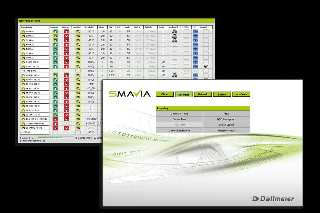
7 5 Configuration 5.1 Track Mode SMAVIA Appliances with BANK license are specially adapted for the use in credit and currency exchange institutions regarding to the used track mode. In the Manual track mode the entire video memory will be segmented into memory units automatically. Every camera / track is assigned manually a particular number of the memory units (track size). Thereby, static tracks will be defined. The size of the tracks can be modified at any time without the need to delete recordings. ¾Open the Recording Settings dialogue via Setup > Recording > Cameras/Tracks. Fig. 1 ¾Set the number of memory units in the Units column. ¾Note the reserved hard disk capacity in the HDD column. ¾Proceed as described for all relevant tracks. ¾Finally confirm with OK. Recording The recordings will be saved continuously into a memory unit of the corresponding track. When the memory unit is filled, the track s next empty memory unit will be used. When no empty memory unit of the track is available, the track s oldest memory unit will be deleted and used for the current recording. 7
8 Modifications At any time the size of the tracks can be increased by adding memory units. The recordings do not have to be deleted. The size of the tracks can be decreased by removing memory units anytime. At first empty memory units will be removed. If no empty memory units are available, the oldest will be deleted and removed. Further recordings in the track do not have to be deleted. Tracks can be dropped and new tracks can be created without deleting other tracks or recordings. The video quality settings can be modified at any time. The recordings in the corresponding track do not have to be deleted. 8
9 5.2 Track Types SMAVIA Appliances with BANK license are specially adapted for the use in credit and currency exchange institutions regarding to the used track types and track names. The corresponding track names of an appliance without this license are given in brackets. Longplay (Longplay) Longplay tracks are generally large ring memories. They are used for ongoing recording. One Longplay track is available for each camera. The recording within Longplay tracks should be configured with the Recording Mode Motion. Note that third-party IP cameras can only record in the recording mode Permanent or Contact. Hold-up (Saving) Hold-up tracks are generally relatively small ring memories. One Hold-up track can be assigned to each camera. Different recording modes can be defined for the Longplay track and the Hold-up tracks. As soon as a hold-up alarm is triggered the Hold-up tracks are saved. This ensures that current images cannot be overwritten. The recording is then continued in a new Hold-up track. The recording in the Hold-up tracks must be configured with the Recording Mode Permanent. Note that the Hold-up track type cannot be selected for third-party IP cameras. Saved Hold-up (Secure track) Hold-up tracks are called Saved Hold-up when they were protected from being overwritten. Depending on the number of triggered alarms, more than one Saved Hold-ups may exist for each camera. Suspicion (without correspondet) The Suspicion track is a mixed track where images from various cameras can be saved. If configured in the Recording Settings dialogue the recording of the cameras is triggered by pressing of the suspicion button. During the evaluation of the suspicion track the camera buttons can be used as filters. The recording in the Suspicion track must be configured with the Recording Mode Contact. Reference track (Reference track) Only individual camera images are saved in the reference track. These can be used to compare the current camera settings and positions with the original situation. Reference tracks are therefore not used for recording purposes and neither can they be played back. 9
10 5.3 Hold-up Recording A hold-up alarm is triggered by an alarm switch which is connected to the Contact IN (configured by the function Start Alarm) interface of the appliance. When an alarm is triggered, the recording of the hold-up cameras in the hold-up tracks is continued for the duration of the alarm. Afterwards the hold-up tracks are saved and recording is continued in new hold-up tracks. A configuration for the use in credit and currency exchange institutions regards the following requirements: Recordings of the hold-up cameras must be available and saved 15 minutes before and after triggering. Recording must be made 15 minutes before and after triggering with a minimum of 2 frames per second. Recordings of the hold-up cameras must be made with a resolution of at least pixels. The recordings of at least two hold-ups have to be stored and secured. ¾Open the Recording Settings dialogue via Setup > Recording > Cameras/Tracks. Fig. 2 ¾Make sure, that enough storage capacity is available (Disk occupation). ¾Open the Hold-up dialogue via Settings... > Hold-up. 10
11 5.3.1 Length of the Hold-up Tracks The length of hold-up tracks determines the duration of the recording before and after a triggering. It must last at least 30 minutes. Fig. 3 Length of the hold-up tracks ¾Set the Alarm duration (min.) if required. ¾Set the Pre-alarm duration (min.) if required. The minimum alarm duration of 15 minutes before and after a trigger is set by default and can not be exceeded Data Rate The bit rate (data rate) is a measure of the degree of compression of video data. It thus has a direct impact on the image quality of the recordings. A low bit rate stands for a high degree of compression with a relatively small volume of data. But the image quality also is poor. A high bit rate stands for a low degree of compression with a relatively large volume of data. The image quality is very good. Fig. 4 Bit rate ¾Set the Maximum bit rate (Mbps) if required. 11


12 5.3.3 Number of Hold-up Tracks The number of hold-up tracks determine the number of hold-ups which can be long-termed saved and so are protected against overwriting. Fig. 5 Number of hold-up tracks ¾Set the Minimum number of Hold-up tracks on at least three times the number of channels of the appliance Frame Rate According to the requirements for the use in credit and currency exchange institutions the recording in the Hold-up tracks must take place with a minimum of 2 frames per second (2 fps). ¾Open the Recording Settings dialogue via Setup > Recording > Cameras/Tracks. ¾Right click on the recording button of the relevant camera in the Hold-up track to open the corresponding configuration dialogue. Fig. 6 Recording settings ¾Select the Normal Quality tab (for IP cameras) if required. ¾Set a Frame rate of at least 2 fps. ¾Confirm with OK. 12
 and assigned to the relevant cameras). By triggering the suspicion switch the recordings of the hold-up cameras are saved in the suspicion track for a certain time.")
13 5.4 Suspicion Recording Suspicion recording is triggered by a suspicion switch, which is connected to the Contact IN interface of the appliance (configured with the function Start Recording (Recording Type Contact) and assigned to the relevant cameras). By triggering the suspicion switch the recordings of the hold-up cameras are saved in the suspicion track for a certain time. This doesn t affect the recording in the Longplay- or Holdup tracks. A configuration for the use in credit and currency exchange institutions regards the following requirements: Recordings of the hold-up cameras must be saved in the suspicion track at least 10 seconds after releasing the suspicion switch. Recording must be made with at least 1 frame per second. Recordings of the hold-up cameras must be made with a resolution of at least pixels. There must be capacity to save recordings of at least 99 suspected triggers. Records within the suspicion tracks may not be overwritten before 10 days. ¾Open the Recording Settings dialogue via Setup > Recording > Cameras/Tracks. Fig. 7 ¾Make sure, that enough storage capacity is available (Disk occupation). ¾Open the Suspicion dialogue via Settings... > Suspicion. 13

")
14 5.4.1 Length of the Suspicion Track The length of the suspicion track determines the number of suspected triggers and the point in time when the first pictures are overwritten. The default setting of the recorder is designed from the factory to the storage of 100 suspicion cases of 24 cameras and not be exceeded. Fig. 8 Length of the suspicion track ¾Set the number of Images Frame Rate and Duration According to the requirements for the use in credit and currency exchange institutions the recording in the suspicion tracks must take place with 1 frame per second (1 fps) for at least 10 seconds. ¾Open the Recording Settings dialogue via Setup > Recording > Cameras/Tracks. ¾Right-click on the recording button of the relevant camera in the suspicion track to open the corresponding configuration dialogue. Fig. 9 Recording settings ¾Note that the frame rate is fixed to 1 fps. ¾Set the Contact Recording Duration with at least 10 seconds. ¾Confirm with OK. 14
 and hold-up track (HO-Track). 6.")
15 6 Activity Monitoring The ATM activity monitoring function is desigend to control the recording of cameras that are installed in automated teller machines. It can be used also to control of every camera that record in longplay track (LP-Track) and hold-up track (HO-Track). 6.1 ATM Activity Monitoring The ATM activity monitoring function is relevant for the recording modes Motion and Contact. The function assumes an error (eg insufficient configuration of the image comparison or defective contact sensor) when recording was not raised in a defined period. This error may display a system message and / or sending an alarm host trigger message. When a recording monitored in the ATM activity monitoring dialogue is stopped, no failure is suspected by the function. ¾Open the ATM activity monitoring dialogue via Setup > System > ATM activity monitoring. ¾Select the ATM activity monitoring tab. Fig. 10 ¾Select the required track (LP-Track / HO-Track). ¾Set the maximum timeout for the required cameras / channels. ¾Click the OK button in order to save the settings. 15

16 6.2 Minimum Storage Period The Min. storage period function is relevant for all types of recording. A channel / recording can be defined so that they normally covers a specific time range. Various events can cause a situation in which more images must be included or more memory is required. Recording Mode Motion Contact All recording modes Event More motion than expected. More contacts than expected Increased storage requirements due to lack of image quality When these events occur permanently, the specified time range Min. storage period may be less. In this case, the function assumes an error and can display a system message and / or sending an alarm host trigger message. If a track monitored in the ATM activity monitoring dialogue is too small, the function suspected a failure. ¾Open the ATM activity monitoring dialogue via Setup > System > Options > Recording Monitoring. ¾Select the Min. storage period tab. Fig. 11 ¾Select the required track (LP-Track / HO-Track). ¾Set the minimum duration for the required cameras / channels. ¾Click the OK button in order to save the settings. 16

17 7 Reference Images as PDF The reference image memory is used to compare image quality and camera perspective for revisions. Thus can be determined, whether the lens has been adjusted or the camera has been mechanically modified in the position. The images stored at any given time are so called reference image set. A master reference image set can be sent by together with the current camera images as a PDF document to a defined alarm host. This can be done manually or can be set up as a continuous broadcast (in intervals or at a specific point in time at daily, weekly or monthly). The reference image is compared with the current camera image in the PDF document. Thus, image quality and camera angles can be matched. In addition, the document contains information about camera number and name and the time stamp of the reference image and of the current camera image. Fig. 12 Example page PDF reference images Define Reference Image Set as Master A reference image set must be defined as the master, so this reference image set can be shipped to a PDF document with the current camera images. ¾ Open the Reference Image Memory dialogue via Setup > Recording > Reference Images. 17

.")
18 Fig. 13 ¾Create a new reference image set if required (see documentation SMAVIA Recording Server Configuration). ¾Select the relevant reference image set as Master. ¾Click the OK button in order to save the settings. Send Reference Image Set In order to send a master reference image set to an alarm host, proceed as follows: ¾Open the Alarm-Hosts dialogue via Setup > Network > Alarm Hosts. Fig. 14 ¾Configure the relevant alarm host with the SMTP connection type (see documentation SMAVIA Recording Server Configuration). ¾Open the Configuration PDF reference images via the Settings button in the Reference images as PDF area. 18
 from the dropdown menu. ¾Click the Send button to start the process.")
19 Fig. 15 Manual Transmission ¾Enable the Send reference images as PDF checkbox. ¾Select in the Send reference images as PDF area the required countdown (immediately, 1, 2, 5 or 10 minutes) from the dropdown menu. ¾Click the Send button to start the process. ¾Click the OK button in order to close the dialogue. The reference image set is sent once after the countdown. Continuous Broadcast ¾Enable the Send reference images as PDF checkbox. ¾Enable the Interval checkbox. ¾Select the required Interval from the dropdown menu or ¾Enable the Point in time option. ¾Select the required option: Daily at, Weekly on oder Monthly on. ¾Set the required daily, weekly or monthly point in time. ¾Click the OK button in order to close the dialogue. The reference image set is sent continuously at the specified point in time of the day, week or month. 19
 Operating system Microsoft Windows 7 Professional (32 Bit) Microsoft Windows 7/8")
20 8 Export The evaluation of the recordings and the export of single images and image sequences is made with the corresponding management software SMAVIA Viewing Client. The client computer has to meet the following requirements: Component Minimum Best Practice (recommendation) Operating system Microsoft Windows 7 Professional (32 Bit) Microsoft Windows 7/8 Professional (64 Bit) CPU 2,66 GHz Dual-Core 3,6 GHz Quad-Core RAM 2 GB DDR3 8 GB DDR3 Recommended NVidia GeForce GT 640 GDDR5 NVidia GeForce GTX 750 graphics board Network 100 Mbit/s 1000 Mbit/s Note the corresponding data sheet and the documentations on SMAVIA Viewing Client for further information. 8.1 Single Images The function Image Export allows to save single images locally or export them to an external storage device. ¾Activate the playback mode of the required camera. ¾Select with the search functions the required image. The function Image Export can be activated with the menu Action > Image > Export or with the control panel as described in the following. ¾Click the Picture processing button. The control panel for the image export is displayed. Fig. 16 ¾Click the Export this picture button. The Export/Print dialog is displayed. 20
 option allows to print the image with all the individual image changes as it is displayed on the screen.")

21 Fig. 17 ¾Select the required option (see below). ¾Click OK. The Save as dialog in the Windows Explorer is displayed. ¾Enter a name for the image. ¾Select a storage medium and / or a directory if required. ¾Click Save. The Modified (WYSWG) option allows to print the image with all the individual image changes as it is displayed on the screen. With the Original option the unaltered original image is printed as it is stored in the track. 8.2 Image Sequences The Backup function allows to backup image sequences of a track. Backups can also be saved to external storage media. Backups can be played in SMAVIA Viewing Client as local tracks. ¾Activate the playback mode of the required camera. The function Backup can be activated with the menu Action > Secured > Backup or with the control panel as described in the following. ¾Click the Create backup button in order to open the backup control panel. Fig

22 Set Start And Stop Time Of The Backup ¾Click the Start time button. The Set start time dialog is displayed. Fig. 19 Note: The Current button allows you to take over the Date and the Time of the currently displayed image. ¾Enter the Date and the Time. ¾Confirm with OK. The start time is displayed in the Start field in the Backup info window. ¾After defining the Start time click the Stop time button and proceed analogously to the start time. Set Target Folder For The Backup ¾Click the Define target folder button. The Save as Windows dialog is displayed. ¾Select with the Windows Explorer the required directory. ¾Enter a name for the backup. ¾Click Save. Start Backup ¾Click the Start backup button. The current backup process is displayed in the Backup working dialog: 22
 or the live mode")
23 Fig. 20 The progress of the backup is displayed in the % bar. Exit Backup Mode After the backup is complete you can activate the playback mode (click on the Create backup button) or the live mode (click on the Live access button) of the current camera. 23
Datasheet. Version 3.8. License Plate Recognition + Red Light Violation Detection. Datasheet LPR + RLVD Version
 Datasheet License Plate Recognition + Red Light Violation Detection AllGoVision Technologies Pvt Ltd Version 3.8 This Specification Sheet gives the details of system requirements, features and other salient
CompleteView Alarm Client User Manual. CompleteView Version 4.6.1
 CompleteView Alarm Client User Manual CompleteView Version 4.6.1 Table of Contents Introduction... 1 Overview...2 System Requirements...2 Configuration... 3 Starting the Alarm Client...3 Menus...3 File
Avigilon Control Center System Integration Guide
 Avigilon Control Center System Integration Guide with Velocity INT-HIRSCH-A-Rev3 Copyright 2013 Avigilon. All rights reserved. No copying, distribution, publication, modification, or incorporation of this
Avigilon Control Center System Integration Guide
 Avigilon Control Center System Integration Guide with Picture Perfect 4 INT-PP4-A-Rev1 Copyright 2012 Avigilon. All rights reserved. No copying, distribution, publication, modification, or incorporation
Avigilon Control Center 5 System Integration Guide
 Avigilon Control Center 5 System Integration Guide for Paxton Net2 Access Control Systems 2014 Avigilon Corporation. All rights reserved. Unless expressly granted in writing, no license is granted with
English. User Manual. Software. PGuard Multiuser. Rev /
 English User Manual Software PGuard Multiuser Rev. 1.0.0 / 070810 Software PGuard-Multiuser Copyright All rights reserved. This document may not be copied, photocopied, reproduced, translated, transferred
Avigilon Control Center 5 System Integration Guide
 Avigilon Control Center 5 System Integration Guide with Hirsch Velocity INT-HIRSCH-B-Rev1 2012 2014 Avigilon Corporation. All rights reserved. Unless expressly granted in writing, no license is granted
Avigilon Control Center System Integration Guide
 Avigilon Control Center System Integration Guide with Gallagher Command Centre INT-CARDAX-C-Rev2 Copyright 2011 Avigilon. All rights reserved. No copying, distribution, publication, modification, or incorporation
Datasheet Face Recognition [Genetec VMS]
![Datasheet Face Recognition [Genetec VMS]](/thumbs/87/95576125.jpg "Datasheet Face Recognition [Genetec VMS]") Datasheet Face Recognition [Genetec VMS] Version 3.6 This Specification Sheet gives the details of system requirements, features and other salient points of AllGoVision Face Recognition application for
Datasheet Face Recognition [Genetec VMS] Version 3.6 This Specification Sheet gives the details of system requirements, features and other salient points of AllGoVision Face Recognition application for
IndigoVision Alarm Panel. User Guide
 IndigoVision Alarm Panel User Guide THIS MANUAL WAS CREATED ON 2/21/2017. DOCUMENT ID: IU-AP-MAN002-4 Legal considerations LAWS THAT CAN VARY FROM COUNTRY TO COUNTRY MAY PROHIBIT CAMERA SURVEILLANCE. PLEASE
Avigilon Control Center System Integration Guide
 Avigilon Control Center System Integration Guide with Gallagher Command Centre INT-CARDAX-C-Rev3 Copyright 2013 Avigilon. All rights reserved. No copying, distribution, publication, modification, or incorporation
Avigilon System Integration Guide. Avigilon Control Center with AMAG Symmetry Security Management System 7.0
 Avigilon System Integration Guide Avigilon Control Center with AMAG Symmetry Security Management System 7.0 2013-2016, Avigilon Corporation. All rights reserved. AVIGILON, the AVIGILON logo, HDSM, HIGH
AC2000 Security Hub Security and Event Management System
 AC2000 Security Hub Security and Event Management System Features that make a difference: Centralised central alarm management application for Access Control, Video, Fire, Intruder and Building Management
Avigilon Control Center 5 System Integration Guide
 Avigilon Control Center 5 System Integration Guide with Lenel Facility Commander Wnx INT-FCWNX-A-Rev1 2010 2014 Avigilon Corporation. All rights reserved. Unless expressly granted in writing, no license
HikCentral Web Client. User Manual
 HikCentral Web Client User Manual Legal Information User Manual 2018 Hangzhou Hikvision Digital Technology Co., Ltd. About this Manual This Manual is subject to domestic and international copyright protection.
Avigilon Control Center 5 System Integration Guide. with STENTOFON AlphaCom. INT-STENTOFON-C-Rev1
 Avigilon Control Center 5 System Integration Guide with STENTOFON AlphaCom INT-STENTOFON-C-Rev1 2013 2014 Avigilon Corporation. All rights reserved. Unless expressly granted in writing, no license is granted
Please use authentic SATA hard drive, USB device and battery.
 Note The device should be set in the room with good ventilation, far from water, hot reservoir or dust. Network Video Recorder is not designed to be used outdoor. Please use authentic SATA hard drive,
Alarm Manager Plug-in
 Alarm Manager Plug-in User s Guide While every attempt is made to ensure both accuracy and completeness of information included in this document, errors can occur, and updates or improvements may be implemented
HikCentral Web Client. User Manual
 HikCentral Web Client User Manual Legal Information User Manual 2018 Hangzhou Hikvision Digital Technology Co., Ltd. About this Manual This Manual is subject to domestic and international copyright protection.
i-vu CCN 4.0 Owner s Guide
 i-vu CCN 4.0 Owner s Guide CARRIER CORPORAION 2007 A member of the United echnologies Corporation family. Stock symbol UX. 11-808-377-01 07/07 able of Contents ACCESSING YOUR SYSEM... 3 YOUR SYSEM DEAILS...
Patriot Systems Limited
 COPYRIGHT 1997 - The Patriot Systems Ltd. Patriot Alarm Monitoring Automation Package is licensed for use on one computer, by the original person, or company, or organization whose name is registered with
Milestone XProtect Alarm Matrix Integration 1.0
 Milestone XProtect Alarm Matrix Integration 1.0 Milestone XProtect Alarm Matrix Integration 1.0 Target Audience This document is aimed at system users and provides descriptions on how to install, configure
Before you install ProSeries Express Edition software for network use
 Before you install ProSeries Express Edition software for network use The following pages describe system requirements and other information you need to know before installing ProSeries Express Edition
Milestone XProtect Alarm Matrix Integration 1.0
 Milestone XProtect Alarm Matrix Integration 1.0 Milestone XProtect Alarm Matrix Integration 1.0 Target Audience This document is aimed at system users and provides descriptions on how to install, configure
1 Introduction Data transmission Compatibility IPS Analytics configuration... 3
 Configuration Instruction Integration of IPS Video Analytics on Axis Cameras with a Milestone XProtect Video Management System Contents 1 Introduction... 1 2 Data transmission... 2 3 Compatibility... 3
UD-VMS510i. Surveillance Management Center
 Surveillance Management Center Introduction VMS510i is a flexible, scalable, high reliable and powerful central management system. Client-Server Architecture, Integrating with multiple surveillance systems.
Operation Manual Fighter ProVision Software. Version: 0.0 Revision: 1
 Operation Manual Fighter ProVision Software Version: 0.0 Revision: 1 TABLE OF CONTENTS 1. Introduction 5 2. Software Installation 5 3. PC Users 6 3.1 Introduction 6 3.2 Default Code 6 3.3 Edit PC User
Milestone XProtect. Central 3.7 User s Manual
 Milestone XProtect Central 3.7 User s Manual Target Audience for this Document This document is intended for end users of the Milestone XProtect Central surveillance system monitoring solution, such as
Table of Contents. i-vu CCN Standard 4.2
 i-vu CCN Standard 4.2 Owner's Guide CARRIER CORPORATION 2009 A member of the United Technologies Corporation family Stock symbol UTX Catalog No. 11-808-381-01 7/13/2009 Table of Contents Accessing your
Architectural and Engineering Specification for a Security Management System. StarNet 2
 Architectural and Engineering Specification for a Security Management System StarNet 2 Jan 2, 2018 Page 1 of 12 AE-S2-IN-R1-EN-01/18 This document is intended to provide performance specifications and
Oracle Communications Performance Intelligence Center
 Oracle Communications Performance Intelligence Center System Alarms Guide Release 10.2.1 E77506-01 June 2017 1 Oracle Communications Performance Intelligence Center System Alarms Guide, Release 10.2.1
Configuring IndigoVision Control Center. Configuring IndigoVision Control Center
 Control Center Prerequisite: IndigoVision Control Center 4.7 build 25 or later Sightlogix Firmware: 5.4.6829 or later Control Center Note: This functionality is only available if you have administrator
Patriot Systems Limited
 COPYRIGHT 1997 - The Patriot Systems Ltd. Patriot Alarm Monitoring Automation Package is licensed for use on one computer, by the original person, or company, or organisation whose name is registered with
LineGuard 2300 Program User Manual (FloBoss 107)
") Form A6251 Part Number D301346X012 November 2012 LineGuard 2300 Program User Manual (FloBoss 107) Remote Automation Solutions Revision Tracking Sheet November 2012 This manual may be revised periodically
Form A6251 Part Number D301346X012 November 2012 LineGuard 2300 Program User Manual (FloBoss 107) Remote Automation Solutions Revision Tracking Sheet November 2012 This manual may be revised periodically
Datasheet Crowd Management
 Datasheet Crowd Management Version 3.78 This Specification Sheet gives the details of system requirements, feature details and other salient points of AllGoVision s Crowd Management applications. Revision
Milestone SMI Intrepid II Perimeter Module 1.1 User s Manual
 Milestone SMI Intrepid II Perimeter Module 1.1 User s Manual Target Audience for this Document This document is aimed at system users and provides descriptions on how to install and maintain the Milestone
Added password for IP setup page : Password must be in IP format!
 NETWORK POWER MONITOR Release : 21 August 2014 Hardware Version : Version 7 Firmware version 1.00 PC Application Software : Version (latest)...2 Added password for IP setup page : Password must be in IP
Installing ProSeries software for stand-alone use
 Welcome to ProSeries tax software For information about this topic... Look here... Getting ready Page 1 Installing ProSeries software for stand-alone use Page 1 Setting up the ProSeries program Page 3
Supervisor Standard Edition
 Supervisor Standard Edition Installation Manual Heat-Tracing Controller Configuration and Monitoring Software INSTALL-119 (Europe) 1 / 18 Contents Section 1 Introduction...3 1.1 Welcome...3 1.2 Vital Information...3
Before you install ProSeries software for network use
 Before you install ProSeries software for network use The following pages describe system requirements and other information you need to know before installing ProSeries software for network use. Important:
Alarm Client. Installation and User Guide. NEC NEC Corporation. May 2009 NDA-30364, Revision 9
 Alarm Client Installation and User Guide NEC NEC Corporation May 2009 NDA-30364, Revision 9 Liability Disclaimer NEC Corporation reserves the right to change the specifications, functions, or features,
Centroid Snet 2. Battery Management Software. User Manual V1.1. Eagle Eye Power Solutions, LLC Keeping an Eye on Your Critical Power!
 Eagle Eye Power Solutions, LLC Keeping an Eye on Your Critical Power! Centroid Snet 2 Battery Management Software User Manual V1.1 www.eepowersolutions.com Tel: 1-877-805-3377 info@eepowersolutions.com
rvm4c Installation Guide Remote Video Module
 rvm4c EN Installation Guide Remote Video Module rvm4c Installation Guide Installation Diagrams EN 2 Installation Diagrams for the Transmitting Unit rvm4c Installation Guide Basic Hardware Installation
Configuring Alarm Rule for Video Analytics Detector
 Configuring Alarm Rule for Video Analytics Detector Introduction Security Management System supports defining multiple detectors of same video analytics feature for a single camera. Eg, 2, 3 etc. can be
IndigoVision. GAI-Tronics Integration Module. Administrator's Guide
 IndigoVision GAI-Tronics Integration Module Administrator's Guide GAI-Tronics Integration Module THIS MANUAL WAS CREATED ON 10 APRIL 2013. DOCUMENT ID: IU-IM-MAN019-1 Legal Considerations LAWS THAT CAN
Fig.: A fire in a server room or data center may cause devastating damage. Protect your infrastructure.
 Didactum`s IP-based monitoring devices have many uses: Monitoring of wiring closets and server room environments Remote monitoring of technical rooms in branch offices Monitoring of power supply systems
Simplex Panel Interface Guide
 Simplex Panel Interface Guide February 2016 SATEON Software Integrations Simplex Panel Interface Guide Issue 1.0, released February 2016 Disclaimer Copyright 2016, Grosvenor Technology. All rights reserved.
Cardax System Comparison
 System Comparison Hardware FT Series 5 Syst Com 131102 Syst Com 131102 2 Contents 1. Introduction... 5 2. System Diagrams... 7 3. Hardware Comparison... 10 4. Comparison... 11 Syst Com 131102 3 Syst Com
USER MANUAL DexTempTM 1000 Temperature Monitor (P/N: IR-1001) DexTempTM 1000 USB Non-Contact Temperature Monitor. User Manual.
 DexTempTM 1000 USB Non-Contact Temperature Monitor. User Manual.") USER MANUAL DexTempTM 1000 Temperature Monitor (P/N: IR-1001) DexTempTM 1000 USB Non-Contact Temperature Monitor User Manual 8690 Rev B Update: 10/24/2013 1 Table of Contents 1 Introduction.. 3 2 Host
USER MANUAL DexTempTM 1000 Temperature Monitor (P/N: IR-1001) DexTempTM 1000 USB Non-Contact Temperature Monitor User Manual 8690 Rev B Update: 10/24/2013 1 Table of Contents 1 Introduction.. 3 2 Host
MegaPower CPU ADMPCPU
 MegaPower CPU ADMPCPU Administrator s Guide 8200-0421-03 J MegaPower CPU Administrator s Guide Figure 1. MegaPower 3200 Video-Matrix Closed-Circuit Television (CCTV) System Cameras Video Data ADDL* Protocol
Datasheet Video Based Fire & Smoke Detection
 Datasheet Video Based Fire & Smoke Detection Version 3.6 AllGo Embedded Systems Pvt. Ltd. 2729, 80 Feet Road, HAL 3 rd Stage Indira Nagar, Bangalore-560038, India Telephone: +91-80-4330-3100 Email: agv_contact@allgosystems.com
CAN unit for Analog Sensors
 CAN unit for Analog Sensors Didactum`s Monitoring Systems have many uses: Monitoring of wring closets and server room environments Remote monitoring of technical rooms in branch offices Monitoring of power
AUTOMATION. Operator s Manual RST Series Web Enabled Input Module. Rev. A2, 1/12
 AUTOMATION P R O D U C T S GROUP, INC. Operator s Manual RST-5000 Series Web Enabled Input Module Rev. A2, 1/12 Tel: 1/888/525-7300 Fax: 1/435/753-7490 www.apgsensors.com E-mail: sales@apgsensors.com RST-5000
Avigilon System Integration Guide. for the Avigilon Control Center and Access Control Manager
 Avigilon System Integration Guide for the Avigilon Control Center and Access Control Manager 2014-2016, Avigilon Corporation. All rights reserved. AVIGILON, the AVIGILON logo, AVIGILON CONTROL CENTER,
Before you install ProSeries software for network use
 Before you install ProSeries software for network use The following pages describe system requirements and other information you need to know before installing ProSeries software for network use. Important:
data logger DL200H DL200D DL200L
 Operating manual data logger DL200H DL200D DL200L TRT-BA-DL200HDL-WM-01- Trotec GmbH & Co. KG Grebbener Str. 7 D-52525 Heinsberg Tel. +49 2452 962-400 Fax +49 2452 962-200 www.trotec.com E-Mail: info@trotec.com
CompleteView SightLogix Sensor Setup Manual. CompleteView Version 4.7.1
 CompleteView SightLogix Sensor Setup Manual CompleteView Version 4.7.1 Table of Contents Contents Introduction... 3 Setup the SightLogix Sensor s Video in CompleteView... 4 Configuring the SightLogix Sensor
Monitoring Operator Guide. Access Control Manager Software Version
 Monitoring Operator Guide Access Control Manager Software Version 5.10.10 2018, Avigilon Corporation. All rights reserved. AVIGILON, the AVIGILON logo, ACCESS CONTROL MANAGER, ACM, ACM VERIFY AND TRUSTED
KEY FEATURES EASY ACCESS. Through web browser for both clients and administrators CLIENT MONITORING. Not dependent on access to site network
 Remote Monitoring of All Sites in One Tool Monitor energy and performance on multiple sites Statistics on energy produced Instant status overview KPI (Key Performance Indicators) Alarms Detect underperforming
D-Link Central Management System
 D-Link Central Management System This seamless management of digital video, audio and data is a powerful solution for large scale installations The D-Link Central Management System is a powerful system
Instruction manual MTL process alarm equipment. October 2016 CSM 725B rev 2 MTL RTK 725B. Configuration Software Manual
 Instruction manual MTL process alarm equipment October 2016 CSM 725B rev 2 MTL RTK 725B Configuration Software Manual SECTION 1 - INTRODUCTION... 5 Basic Requirements... 5 SECTION 2 - SOFTWARE INSTALLATION...
Installing ProSeries 2005
 Installing ProSeries 2005 The following instructions will walk you through Installing and Launching ProSeries 2005. Before you begin your installation, it is very important to make note of the following
USER S GUIDE. AXIS Cross Line Detection
 USER S GUIDE AXIS Cross Line Detection User s Guide Rev. 1.00 Copyright Axis Communications AB, 2009 November 2009 Part no. 36687 AXIS Cross Line Detection AXIS Cross Line Detection is a trip-wire application
3D_ISS. Integrated Software System. User Guide Manual
 3D Digital Design & Development LTD 58/60 Edward Road Tribec House New Barnet EN4 8AZ 020 8440 7060 3D_ISS Integrated Software System User Guide Manual Copyright 2014 3D Digital Design and Development
Typical applications include the vibration detector. Detection of vibrations and shocks
 Didactum`s IP-based monitoring devices have many uses: Monitoring of wiring closets and server room environments Remote monitoring of technical rooms in branch offices Monitoring of power supply systems
Combined CAN Sensor Unit Temperature, Humidity and Smoke
 Combined CAN Sensor Unit Temperature, Humidity and Smoke Didactum`s IP-based monitoring devices have many uses: Monitoring of wiring closets and server room environments Remote monitoring of technical
AK-CS On Board Guide
 MAKING MODERN LIVING POSSIBLE AK-CS On Board Guide electronic controls & sensors About this guide The AK-CS On Board guide highlights the use of the RMT tool, allowing remote software management. Consult
Notice... 1 Trademarks... 1 US Patent Numbers... 1 Technical Services Contact Information... 2 Document Conventions... 2 Warranty...
 Table of Contents Preface 1 Notice... 1 Trademarks... 1 US Patent Numbers... 1 Technical Services Contact Information... 2 Document Conventions... 2 Warranty... 2 Chapter 1 Radius Overview 6 1.1 About
VMD Guide for V960 Series Cameras
 Configuration Guide XX206-40-01 VMD Guide for V960 Series Cameras Vicon Industries Inc., 89 Arkay Drive, Hauppauge, New York 11788 Tel: 631-952-2288 Fax: 631-951-2288 Toll Free: 800-645-9116 24-Hour Technical
User Manual. Software. PGuard II. Dallmeier electronic GmbH. DK GB / Rev /
 User Manual Software PGuard II 1 DK 200.003 GB / Rev. 4.1.1 / 040809 Software PGuard II Copyright & Co.KG, 2004 All rights reserved. This document may not be copied, photocopied, reproduced, translated,
Welcome to ProSeries Express Edition tax software
 Welcome to ProSeries Express Edition tax software ProSeries Express Edition is designed for tax professionals who file 50 or more bank product tax returns each season. ProSeries Express offers: An innovative
VMD Guide for MP-980 Cameras
 Configuration Guide XX206-10-01 VMD Guide for MP-980 Cameras Vicon Industries Inc., 89 Arkay Drive, Hauppauge, New York 11788 Tel: 631-952-2288 Fax: 631-951-2288 Toll Free: 800-645-9116 24-Hour Technical
Integration Test Plan
 Integration Test Plan Terminus Security Prepared by: Kai Chan Stephen Krenzel John O Meara Version: 1.0 1 Contents 1 Introduction 3 1.1 Purpose.................................. 3 1.2 Scope...................................
System Galaxy Quick Guide
 System Galaxy Quick Guide CONFIGURATION AND OPERATION Integrating CCTV with System Galaxy JAN 2019 SG 11.1.0.2 System Galaxy Quick Guide For CCTV Integration Configuration & Operation Information in this
Chapter. Configuring Genetec Omnicast. Version 4.7 SR1. Configuring Third-Party Programs. SightLogix, Inc
 Configuring Genetec Omnicast Version 4.7 SR1 2 Chapter Configuring Third-Party Programs SightLogix devices are used with two types of third-party programs: VMS programs, which display video, GPS coordinates,
Netbiter Tank Sensor
 For Netbiter Tank Sensor HMS Industrial Networks AB Post address: Box 4126 300 04 Halmstad SWEDEN Visitor s address: Stationsgatan 37 302 45 Halmstad SWEDEN Telephone: + 46 35 17 29 00 Fax: + 46 35 17
Monitor Alarms and Events
 This chapter contains the following topics: What Are Alarms and Events?, page 1 How are Alarms and Events Created and Updated?, page 2 Find and View Alarms, page 3 Set Alarm and Event Management Preferences,
PWM. Solar Charge controller with Ethernet. Solar Smart PWM 20Amp. Hardware Description : Release : 19 June 2014
 Solar Charge controller with Ethernet Release : 19 June 2014 Hardware Version : Version 1 Firmware version 1 PC Application Software : Version 1.0.0.0 Hardware Description : The Solar Smart regulator was
Managing Network Alarms and Events
 10 CHAPTER Prime Performance Manager allows you to view alarms and events that occur in your network. The following topics provide information about displaying network alarms and events: Displaying Active
Avigilon System Integration Guide. for the Avigilon Control Center and Access Control Manager
 Avigilon System Integration Guide for the Avigilon Control Center and Access Control Manager 2014-2017, Avigilon Corporation. All rights reserved. AVIGILON, the AVIGILON logo, ACC, AVIGILON CONTROL CENTER,
DC Voltage Sensor. Specifications Didactum DC sensor: The sensor is automatically detected by the Didactum base unit. Accuracy: 1%
 DC Voltage Sensor Didactum`s IP-based monitoring devices have many uses: Monitoring of wiring closets and server room environments Remote monitoring of technical rooms in branch offices Monitoring of power
ViewMatrix. Software for Online Monitoring & Control of Matrix2000 Conventional Fire Alarm Panels. Version: 2.0 Revision: 0.1
 ViewMatrix Software for Online Monitoring & Control of Matrix2000 Conventional Fire Alarm Panels Version: 2.0 Revision: 0.1 CONTENTS 1. Introduction...3 2. Keyboard...5 2.1 POWER indication - Normal Operation...5
Instruction Manual. Digital Recorder. Model SDR-304. Make sure all the accessories are supplied together. Introduction Connection. Operation.
 Digital Recorder Instruction Manual Model SDR-304 Function r - ACCESS ALARM REMOTE WARNING TIMER MENU ENTER SHIFT Setting Others Make sure all the accessories are supplied together. AC120V NTSC CAUTION
Step 1 - Install ProSeries Basic software
 Welcome to ProSeries Basic tax software Please follow steps 1 through 3 in this guide: For this step... Look here... Getting ready Page 1 Step 1 - Install ProSeries Basic softwarepage 1 Step 2 - Set up
Outdoor Temperature Sensor
 Didactum`s IP-based monitoring devices have many uses: Monitoring of wiring closets and server room environments Remote monitoring of technical rooms in branch offices Monitoring of power supply systems
Configuration and Operation Manual for the Unipos
 AxxonSoft Configuration and Operation Manual for the Unipos Integration Module Version 1.1 Moscow 2010 Contents CONTENTS... 2 1 LIST OF TERMS... 4 2 INTRODUCTION... 6 2.1 Document purpose... 6 2.2 Purpose
OVEN INDUSTRIES, INC.
 OVEN INDUSTRIES, INC. OPERATING MANUAL Model 5C7-252 TEMPERATURE CONTROLLER With PLC Inputs Introduction Thank you for purchasing our controller. The Model 5C7-252 is an exceptionally versatile unit and
Interfacing with the ADAM Module
 Introduction Interfacing with the ADAM Module Fiber SenSys, Inc. (FSI) has goal to provide our customers with the best security solution available to fulfill their project requirements. Our design and
Operating instructions
 MA00929301 09/2015 Operating instructions ED10429002 ESYLUX GmbH An der Strusbek 40 22926 Ahrensburg Germany info@esylux.com www.esylux.com 1 Table of contents 1 Using the manual 8 2 Safety instructions
1. Functions of GPS locator ETLOC-30S 3
 Contents 1. Functions of GPS locator ETLOC-30S 3 1.1 Direct view of the vehicle position on the map 3 1.2 Vehicle security 3 1.2.1 Vehicle protection 3 1.2.1.1 GPS protection 3 1.2.1.2 GPS higher level
Tech Data Sheet D01662GB0_Esgraf 4.1 and Configuration Server 30/2011 2/(5)
") Tech Data Sheet D01662GB1_Esgraf 4.1 and Configuration Server 30/2011 1/(5) Esgraf 4.1 graphical user interface, configuration server and fire detectors contamination monitoring Esgraf 4.1 ESGRAF is a
Tech Data Sheet D01662GB1_Esgraf 4.1 and Configuration Server 30/2011 1/(5) Esgraf 4.1 graphical user interface, configuration server and fire detectors contamination monitoring Esgraf 4.1 ESGRAF is a
MultiSite Manager. Setup Guide
 MultiSite Manager Setup Guide Contents 1. Introduction... 2 How MultiSite Manager works... 2 How MultiSite Manager is implemented... 2 2. MultiSite Manager requirements... 3 Operating System requirements...
Installing ProSeries 2004
 Installing ProSeries 2004 The following instructions will walk you through Installing and Launching ProSeries 2004. Before you begin your installation, it is very important to make note of the following
Bosch TCU Integration Module Administrator's Guide
 Bosch TCU Integration Module 1.0 - Administrator's Guide 10 Dec 2008 Rev 1.2 Table of Contents 1 Overview... 3 1.1 Compatibility...3 1.2 References...3 2 Installation... 4 3 Configuration... 5 3.1 System
SIMATIC IPC DiagBase SIMATIC. Industrial PC SIMATIC IPC DiagBase. Introduction. DIAG software components. Quick-Start Guide
 Introduction 1 DIAG software components 2 SIMATIC Industrial PC Operating Manual Quick-Start Guide 3 Hardware and software requirements 4 Installing and removing the software 5 Description of the Management
Diagnostics and Monitoring System WEB Tool 2. User Manual
 Diagnostics and Monitoring System 2 (Translation of the original documentation) User Manual S/N: Valid from: 01.05.2012 Rev.: 2.0 2 Rev. 1.... 1 1.1 General information... 1 1.1.1 Equipment... 1 1.1.2
AirFlow Sensor for Dry Contact connection
 Didactum`s IP-based monitoring devices have many uses: Monitoring of wiring closets and server room environments Remote monitoring of technical rooms in branch offices Monitoring of power supply systems
Innovative Industrial Solutions, Inc Skyline Drive Russellville, AR 72802
 The SigniFire IP Camera System is capable of detecting and alarming on a variety of events. Once an alarm occurs it can be signaled through contact closure or by digital streamed transmissions over IP.
Alarm System Example
 Alarm System Example ASD:Suite Copyright 2013 Verum Software Technologies B.V. ASD is licensed under EU Patent 1749264, Hong Kong Patent HK1104100 and US Patent 8370798 All rights are reserved. No part
REMOTE MONITORING AND ALARM SYSTEM
 FUNCTIONALITY A. The water and wastewater facilities remote monitoring, reporting and alarm notification system shall be comprised of a hosted, Web-based user-interface which communicates to remotely monitored