DYGIZONE GJD910 Lighting Controller & Enunciator
|
|
|
- Louise Anthony
- 5 years ago
- Views:
Transcription
 The blue LCD backlight does not come on The display will automatically clear after 1 minute, or if any button is pressed.")

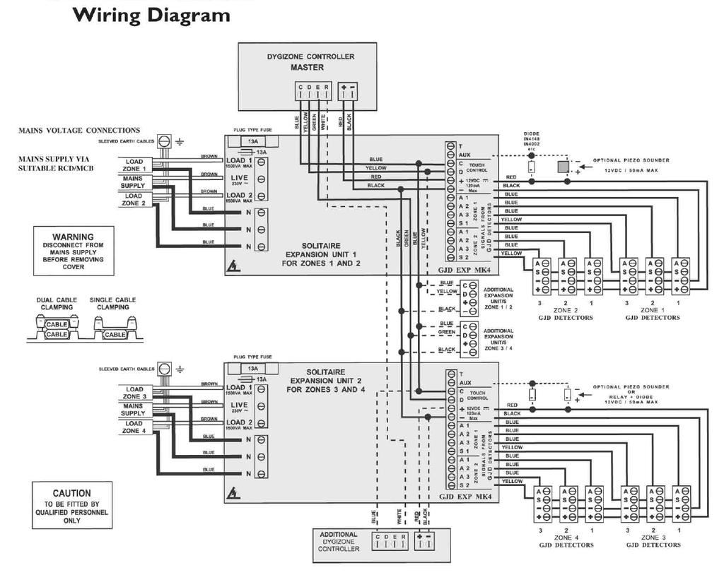
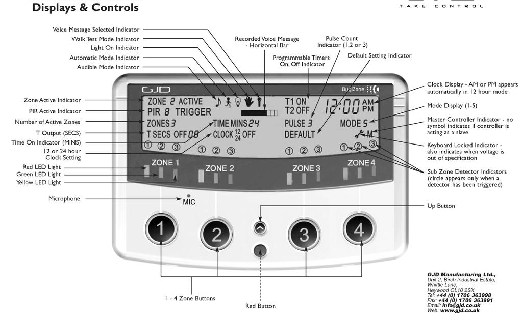
1 DYGIZONE GJD910 Lighting Controller & Enunciator MASTER WIRING IDENTIFICATION Power up to the DygiZone and you will see: All the LED s (red,yellow,green and blue buttons) will flash All the LCD icons will light up (there is no audible noise) The blue LCD backlight does not come on The display will automatically clear after 1 minute, or if any button is pressed. When the display clears and nothing is activated The LCD displays the clock time (automatically defaults to 00:00) The symbol M appears on the DygiZone which is configured as the master controller: The letter M does not appear when setting up a DygiZone as a slave controller The three zone LED s will display whatever zone state has been last programmed or the default setting. The default setting is audible and automatic for all active zones. Remove insulating strip from clock back up battery on master controller Zone Indicator Icons explained Along the bottom of the LCD display up to three sub-zone circular Icons will be displayed above each numbered Zone button. These will only be displayed when an associated detector connected to A1,A2 or A3 on the Expansion Unit is activated. When corresponding detectors connected to A1,A2 or A3 inputs are activated then- The LCD screen will display the zone number 1,2 and 3 A circle will appear around the zone number if that sub-zone detector is activated The circle flashes on the screen in the same way as the PIR text whenever a PIR is triggered. - i.e. the circle flashes for 8 seconds upon activation and then remains on for pre-programmed time duration (time on ) After that time as elapsed, the circle will disappear. Note: the numbers 1,2 or 3 always remain steady and never flash. When the PIR s have not been activated The large circular bluer Zone buttons (1-4) will not be illuminated The clock and M display will remain visible but all other icons on the LCD are turned off The zone status LED s that are required will be displayed. Zone Status Icons (only visible when the zone button is pushed). At the top in the middle of the LCD, three zone status icons will be displayed in various combinations, depending on how the zone has been set up 1. A light bulb icon represents external lights are on from a detector activation, manual override more or timer operation and mimics the yellow LED 2. The musical note icon is shown when the audible mode is selected and mimics the red LED. 3.If voice message mode has been selected(vs beep) then the microphone icon will also display on the LCD. 4. The stick man icon represents the automatic mode and mimics the green LED -1- LED lights explained Red = Audible Mode - either beep more or voice message mode. Green = Automatic Mode - works in conjunction with the photocell in the detector. The external security lights will only be activated if it is dark and thereby saves energy. Yellow = Manual Override - the external security light will now remain on irrespective of detector status - useful for barbeques or when working outside in the dark for long periods Yellow = Lighting Activated - the external security lights have been activated by a detector and will remain on for the pre set time Yellow = Timer Active - the external security lights are on because the Timer 1 or Timer 2 options are programmed to be active. The DygiZone Control and Monitoring Status can be set individually for each Zone as follows- 1.Pressing a Zone button selects the Zone to be set up. The LED s and the LCD display icons will display the current status e.g. Green LED and stick man means auto more has been selected. 2. A second press on the same button will now light the red LED (green LED turns off). The musical note icon will now show on the LCD plus a microphone symbol if voice message has been selected. 3.Pressing the zone button again will turn off all the LED s and icons. 4. Press once more and the yellow LED lights and the light bulb icon displays in the LCD. This now sets the DygiZone to manual mode for that specific zone and the lights will come on and stay on. 5.One more press and both the green and the red LED s come on indicating that audible and automatic mode have been selected. LOCKING THE KEY PAD Locking the key pad prevents accidental programme or settings changes. To Lock - press and hold down the Zone buttons 1 and 4 at the same time - a single beep will be hear and the spanned symbol on the keypad will flash to confirm that the key pad is locked. To unlock - repeat the action and two beeps will be heard, and the spanner symbol will disappear When a PIR detector in a zone is triggered, the following zone information is displayed - LCD Information and Text PIR text will flash for approximately 8 seconds for that zone The blue LCD backlight will come on for about 6 seconds during the trigger state and will remain on after the trigger has occurred. The text remains on for a time duration (time-on) equal to the time that has been pre-set in the Mins Setting. If the DygiZone is triggered during the hours of darkness: The external security light will also be activated for the pre-set time. Note: If another PIR activation occurs on any other zone then the text will be displayed for that new zone for the same pre-programmed time on duration Recording a voice message to audible indicate which zone has been activated 1. Press and hold the red button until the microphone symbol appears on the LCD 2. Press the required Zone button once and then release. As you release the zone button a horizontal bar with ten segments will appear below the microphone symbol on the LCD. This indicates the amount of recording time available where each segment is equivalent to one second therefore a ten second message can be recorded. 3. Speak into the microphone on the front cover of the DygiZone to indicate location (e.g. patio area, front door, side garden etc) 4. When you have finished speaking into the microphone quickly press the zone button again ( there will be no audio beep). 5. The recorded message will now automatically play back. If you are satisfied with the message do nothing but if you wish to re-record the message repeat steps 1 to Press and hold down the red button until the microphone symbol appears in the LCD and then release. 7. Now press and continue to hold down the zone button for which the voice message is to apply, until an audible beep is heard-release the zone button and the programming has been completed. The voice message mode can be confirmed by pressing the the zone button once and a microphone symbol will appear on the LCD if audible mode has been pre-selected.
2 Note 1: the normal default status for sensor activation is an audible beep. i.e. one beep for Zone 1, two beeps for Zone 2 and so on. Note 2: it is possible to mix both audible beeps and recorded messages. e.g. Zone 1 could be in beep and Zone 2 could be in recorded voice playback. To change from a voice message to a beep, repeat Steps 6 & 7. ENGINEER PROGRAMMING Whichever Zone requires adjustment, press and hold down that Zone button until the programming options show on the LCD display. The ZONES number will be flashing on the LCD display, to change this option press UP button until the required number is showing then press the RED button. If no adjustment is required press the RED button. This will store the change and more on to adjust the TIME MINS. Repeat the above process until all changes have been completed then press and Zone button to exit programming. If no buttons are pressed for 30 seconds the DygiZone will automatically exit the programming mode. SELECTING THE NUMBER OF ACTIVE ZONES 1. Press and hold down the Zone 1 button this will enter programming mode. 2. The Zone number will flash and can be changed using the up arrow button. 3. Press the red button to confirm the number of Zones. Unused zones will be cleared i.e. no LCD information will display and no LED s will work for that Zone. An audible beep will be heard if any of the unused Zone buttons are pressed, but no action will be taken. 4. Press Zone 1 button to exit the programming mode. SETTING THE TIME THAT THE LIGHTS STAY ON When a detector is triggered and if that Zone has been set to the automatic mode (green LED), the lights will turn on and stay on for the time programmed using the TIME setting in the programme software. This can be selected to be 1,2,3,4,5,8,12,16 or 24 minutes using the red and arrow buttons, When set simply press any of the Zone buttons to exit the programming mode. OPTIONAL DYGIZONE SLAVE CONTROLLERS Up to two additional DygiZone controllers can be connected to the system, additional Expansion Units or power supply will be required to provide the 12 Volt supply. Only the Master controller can be used to set the programmed options but different voice messages can be recorded on the remotely located Slave controllers. The keypad can also be locked on the Slave controllers otherwise the slaves will mimic the Master. Changing a button selection on the Master DygiZone will instantly change the settings on the Slave controllers. Changing a button selection on either of the Slave controllers will instantly change the setting on that Slave and the master, the setting on the other Slave will change within one minute. It is recommended that the DygiZone which will be used the most should be configured as the master. SETTING THE SENSITIVITY OF DETECTORS (PULSE COUNT) The number of beams (pulse count) that need to be triggered before an alarm output activates can be set at 1,2 or 3 can be selected. Note: when using a DygiZone with GJD detectors where the pulse count is set on the detector itself, ensure that the detector pulse count is set to 1. This will apply to D-TECT,OPAL ELITE and OPAL RFX GJD detectors, but does not apply to the OPAL XL detector. -2- Mode Settings One of five modes can be programmed for each Zone. Mode 1-24 hr = Lights operate day and night with detection when auto is selected Mode 2 - Link (Zone 1) = Detectors on Zone 1 also activate lights on Zone 2 when auto is selected Mode 2 - Link (Zone 2) = Detectors on Zone 2 also activate lights on Zone 1 when auto is selected. Mode 2 - Link (Zone 3) = Detectors on Zone 3 also activate lights on Zone 4 when auto is selected. Mode 2 - Link (Zone 4) = Detectors on Zone 4 also activated lights on Zone 3 when auto is selected. Mode 3-24+L = Outside light will operate day and night with detection according to the Link settings above. Mode 4 - STD = Outside lights will only operate at night with detection. Detectors on that Zone will only operate that zone. Mode 5 - ALL = All lights on all Zones that have Mode 5 selected are activated at night with detection from any Zone with Mode 5 selected. Any Zones with ALL selected will be treated as a group. TSEC OUTPUT When this option is selected on the GJD Expansion Unit, the TSEC output will provide a 12 Volt positive switched signal for the selected time (in seconds) i.e. 1,5,10,20 or 30 secs. SETTING THE CLOCK TO 12HR OR 24 HR MODE OR TO CLOCK OFF DISPLAY The clock display must be set to 24hr before the clock time can be set. Use the red and arrow buttons to advance and to set the clock mode. If 12hr mode is selected, AM and PM symbols will automatically appear. The clock can also be selected to display 24hr time or not to display time (clock off) Note: the two timers for each zone will automatically display the time in the format as selected above. If the power is turned off and then on without holding down the Zone 1 & 4 buttons, both the illuminated zone LED s and programme setting will also remain as they were prior to power down - the clock display will however be reset to 00:00. SETTING THE CLOCK 1. Press and hold down any Zone button until the LCD icon for that Zone appears and that Zone button is flashing blue. (the number of zones connected will also be flashing i.e. the number 1,2, or 4) 2. Press the red button six times and the hour digits will begin to flash. 3. Set the hours by using the up arrow and press the red button again to set the hour required. 4. The minute digits will now begin to flash - set the minutes in the same way as the hours. Now press the red button. Now that the clock is set to the correct time, exit the clock setup mode by pressing any of the zone buttons, The time will now display on the LCD clock. SETTING THE VOLUME The volume can be adjusted by turning the potentiometer in the rear of the controller. WALK TEST Walk Test Mode has to be selected for each Zone that is being walk tested. In this mode, as each detector is activated, the audible beep will sound & relevant Zone & PIR Number is displayed on the LCD. The external lights connected to that Zone will turn on for 4 seconds each time a beam is crossed. Each Zone has to be tested individually. When in programming mode (i.e. after pressing and holding one of the Zone buttons until the LCD display icons show) use the red button to scroll to the flashing hand icon. Select the walk test mode by pressing the up arrow when the hand icon is showing. The blue LED flashes all the time until the walk test mode has been exited.
3 To exit walk test mode press the red button once - an audible beep will be heard. The DygiZone will automatically cancel the walk test mode after five minutes from last trigger. SWITCHING THE LIGHTS ON & OFF AT PRE-SET TIMES IN EACH INDIVIDUAL ZONE Each Zone can be programmed to automatically switch the external lights on & off at pre set times. Each Zone has two programmable timers - T1 & T2. 1. Using the red and arrow buttons, advance to the T1 ON time. When the hour digits being to flash, enter in the hour at which you want the lights to turn on, press the red button, repeat for the minutes and press the red button again to set the time. Repeat for the T1 OFF Time and repeat for the T2 timer. Note: if the timers are not required, they should be set to 01:00 for on and off times (default settings). DEFAULT SETTINGS When you purchase a DygiZone it has already been preprogrammed with suggested parameteres which are DEFAULT settings. To return the DygiZone to its default settings - the programming mode,use the red button to scroll to the DEFAULT text icon and when flashing select press the up arrow key. Caution: this will return all settings to default and will also reset the clock Default settings are: Zones active = 4 Light on time = 1 minute Pulse count = 1 T seconds = 5 Clock mode = 24 hr Mode = 4 POWER-UP RESET - REVERTS TO DEFAULT SETTINGS This would normally be initiated by a qualified electrician or security systems installer. Remove power from the DygiZone. Remove battery from master controller. Press and hold down both Zone 1 & 4 button and then re-apply the power. The clock will be reset and the programme will revert to default settings where all the Zones are set to audible and auto modes i.e. the red and green LED s will be lit on all Zones. Replace battery. Note: after a power down & power up, the detectors connected to the GJD expansion Unit will not activate for the following 2 minutes. SPECIFICATIONS Supply: Display: Audible: Control: 12 20mA standby. 100 ma triggered with message playback Blue back-lit LCD display showing real time clock,detector activation and zone status Internal warning tone with individual tones for each zone or selectable 10 second voice recordable message for each zone Four individual zone buttons for selecting zone status and programming options System configuration: Normally 1 Master and 1 Slave DygiZone, One additional Slave can be added if r required. Requires GJD Expansion Units. Time Control: Two individual on/off timers per zone Mounting: Indoor use only, Mount in a clean dry location. Can be mounted on a standard single or double flush back box Temperature: -10 C to +55 C Dimensions: 190g NET, 260g GROSS NOTE: If the two Expansion Units are not powered simultaneously a 4.7KΏ resistor needs to be placed between +ve 12 volt and Data E on the DygiZone connections MAINTENANCE MODE The spanner icon flashes when the keypad is locked and is steady when the supply voltage to the DygiZone is outside the specification i.e.-below 9 volts or more than 14 Volts. IMPORTANT: if the keypad is not locked and the spanner icon is showing steady, please call a maintenance engineer. -3-
4 -4-
5 -5-
6 4 ZONE EXPANSION UNIT WIRING DIAGRAM -6-
7 Display will show Exit Delay Instant Press 3 to change to 30 seconds, Press 6 to change to 60 seconds, Press 0 to return to instant. Press ENTER to save your selection. HOW TO SET THE ARM DELAY SOUND: (Factory Default Silent.) Select whether you want a silent or audible sound on any arm delay. Quick guide: Press > PROGRAM > 7 > ENTER > 1 > ENTER (1 = Audible; 0 = Silent) 1. Key in the four digit user Password code (Factory Default 1234). 2. Press PROGRAM > 7 > ENTER Display will show Exit Delay Sound Silent Press 1 to change to Audible, Press 0 to return to Silent. Press ENTER to save your selection. HOW TO SELECT WHETHER AN OUTPUT IS 5 SECOND MOMENTARY (PULSED) OR TOGGLE LATCHING: (FIRST ACTIVATION LATCHES OUTPUT ON, SECOND ACTIVATION TURNS IT OFF) (Factory Default Momentary.) Quick guide: Press > PROGRAM > 8 > ENTER > 1 > ENTER > N > ENTER > 1 > ENTER (N = Output 1,2,3 or 4; 0 = Timed; 1 = Latched.) 1. Key in the four digit user Password code (Factory Default 1234). 2. Press PROGRAM > 8 > ENTER > 1 > ENTER Display will show Output Press 1 to program Output 1, Press 2 to program Output 2, etc. Display will show Output 1 Timed Press 1 to Latching Toggles, Press 0 to return to instant. Press ENTER to save your selection. HOW TO SELECT THE TIME OF A PULSED MOMENTARY OUTPUT: (Factory Default 5 Seconds.) Quick guide: Press > PROGRAM > 8 > ENTER > 2 > ENTER > N > ENTER > Time > ENTER (N = Output 1,2,3 or 4 Alarm sound time is from 1 minute 99 minutes) 1. Key in the four digit user Password code (Factory Default 1234). 2. Press PROGRAM > 8 > ENTER > 2 > ENTER Display will show Timed Pulse Time Press 1 to program Output 1, Press 2 to program Output 2, etc. Display will show Output Time 5 Seconds Press digits 1-9 to create a time in seconds that you wish to select as the time for that output to activate. Press ENTER to save your selection. HOW TO SELECT WHETHER AN OUTPUT IS EVENT (TRIGGER ACTIVATED) AS WELL AS USER ACTIVATED: (Factory Default User Activated Only) Quick guide: Press > PROGRAM > 8 > ENTER > 3 > ENTER > N > ENTER >1 > ENTER (N = Output 1,2,3 or 4; 0 = User Activated only; 1 = User + Event/Trigger Activated.) -7-
8 1. Key in the four digit user Password code (Factory Default 1234). 2. Press PROGRAM > 8 > ENTER > 2 > ENTER Display will show Output Type Press 1 to program Output 1, Press 2 to program Output 2, etc. Display will show Output Type User Press 1 to select Output as activating on Trigger 1 (if selected, Output 1 will then activate on activation of Trigger 1, Repeat to program Output 2 activating on Trigger 2, etc.). Press 0 to return to User Activation only. Press ENTER to save your selection. HOW TO TURN THE COMMUNICATOR ON/OFF LOCALLY OR REMOTELY How to turn the Communicator ON: (Default ON. That means the Communicator will always be active or ON when power is first applied or re-applied to it. Turn OFF to program and then turn back ON and leave ON) From the Communicator: Quick guide: Press > ENTER 1. Check that the voice message and at least one phone number has been programmed into the Communicator. 2. Press ENTER. The Communicator will show ON on the display. 3. The triggers will become active after the delay time you have set has expired (Default 0 seconds or instant). From a Telephone: Quick guide: Call the Communicator and Press > # 1. Check that the voice message and at least one phone number has been programmed into the Communicator. 2. Call the Communicator (telephone number of the SIM card that has been installed). You will hear a long beep to indicate that the Communicator has answered. The Communicator s display will read Call in. 3. Press (4 digit code) followed by the # key. You will hear 2 beeps to indicate that the Communicator has been turned on and the Communicator will automatically hang up. 4. The triggers will become active after the delay you have set up has expired (default set at 0 seconds, instant). From a Text Message: Quick guide: Text the Communicator with ># then press the return key 1. Check that the voice message and at least one phone number has been programmed into the Communicator. 2. Text the Communicator (telephone number of the SIM card that has been installed) with the message: # - ensure you then press the return key before pressing send so the cursor on your phone is flashing on the next line. The Communicator s display will briefly show a number, being the number of texts it has received to date. 3. The triggers will become active after the time you have set has expired (default set at 0 seconds, instant). -8-
9 How to turn the Communicator OFF: or to stop it dialling out. From the Communicator: Press ESC Communicator will show OFF on the display. This will also stop calls being sent out after it has been triggered. From a Telephone: Quick guide: Call the Communicator and press > * 1. Call the Communicator (telephone number of the SIM card that has been installed). You will hear a long beep to indicate that the Communicator has answered. The Communicator s display will read Call in. 2. Press (4 digit code) followed by the * key. You will hear 4 beeps to indicate that the Communicator has been turned off and the Communicator will automatically hang up. From a Text Message: Quick guide: Text the Communicator with >* then press the return key. Text the communicator (telephone number of the SIM card that has been installed) with the message * - ensure you then press the return key before pressing send so the cursor on your phone is flashing on the next line. The Communicator s display will briefly show a number, being the number of texts is has received to date. HOW TO STOP THE COMMUNICATOR DIALLING THE TELEPHONE NUMBERS IN SEQUENCE; Quick guide: When the phone is answered, Press <#> or <*> on the receiving end s telephone keypad to stop the dialling sequence. When the Communicator starts dialling, it will dial the first telephone number and repeat the pre-recorded voice message three times. The number dialled will appear briefly on the display and the display will then show the Telephone Number, in sequence, being called. If there is no response or acknowledgement (# or * pressed) from that number, then it will dial the next number until all the programmed numbers for that trigger are dialled. If there is no acknowledgement from any of the phone numbers, it will display NO ANSWER. To stop this dial sequence, press the <*> key on the telephone keypad that is receiving the call. At that time, the Communicator will stop its dialling sequence and the alarm (if programmed) will stop. If the local alarm has been programmed as active, then pressing the <#> key will stop the dialling sequence, but the alarm will continue to sound until timed out. In both cases, the Communicator will remain ON, waiting for any further trigger. You can also stop the dial sequence at the Communicator s keypad by entering the 4 digit code and pressing ESC. This will turn the Communicator OFF. HOW TO OPEN LISTEN-IN When answering a Voice Message from the Communicator: Quick guide: Press 9 1. If you wish to open Listen-In at any time, whilst receiving a voice message from the Communicator, press 9 on your telephone keypad. 2. To close the Listen-In, simply hang up. -9-
10 From a telephone: Quick guide: Call the Communicator and Press > 9 1. Call the Communicator (telephone number of the SIM card that has been installed). You will hear a long beep to indicate that the Communicator has answered. The Communicators display will read Call In. 2. Press (4 digit code) followed by the 9 key to open Listen-In. To close, simply hang up. HOW TO RETURN THE COMMUNICATOR TO FACTORY DEFAULT SETTINGS (Note: this can only be done when the Communicator is in the OFF mode.) From the Communicator: Quick guide: Press > ESC > ENTER > > ESC > ENTER 1. Ensure the Communicator is in the OFF mode. 2. Press > ESC > ENTER. The display will read Factory Default Press > ESC > ENTER again to confirm you wish to return to Factory Default Setting. The GJD710 has 4 Outputs that can be programmed: HOW TO TURN THE OUTPUTS ON AND OFF 1. User only (default setting) or Event Follower + User. Event Follower means Output 1 activates when trigger 1 is activated, Output 2 when trigger 2 is activated, and so on. 2. Whether the output is a 5 second pulsed momentary output or a toggle latching output. Toggle Latching Output means that the output remains ON until a further command turns it OFF again. Note: if the output has been programmed as a momentary output, a further programming section selects whether it remains On for a time between 1 and 99 seconds before automatically turning Off. User Activation of the Outputs From the Communicator: Quick guide: Press > 0 > 1 (the number of the output). 1. Press , followed by 0, followed by the number 1-4, being the number of the output you wish to turn ON (Output 1 in this example). 2. The Communicator will show Output 1 on the display. 3. The output will become active for the time which has been programmed (a time of between 1 and 99 seconds if the output has been programmed as a momentary output or latching On until turned Off if it has been programmed as a latching output). 4. To turn a Latching output off, Press , followed by 0, followed by the number 1-4, being the number of the output you wish to turn off. HOW TO INITIATE AN IMMEDIATE TEST CALL OR TEST SMS FROM THE GSM COMMUNICATOR If you wish to receive a Test Voice Call, you will first need to record a Test Message. See How to record the Voice Messages on Page 4. If you wish to receive a Test SMS, you will first need to create a Test SMS (see Page 4). The Test Call or SMS will be sent to those telephone numbers you have selected (default is all numbers will receive a test call). Select whether you wish numbers to receive a Test Voice Call only, Test SMS only or both Voice Call and SMS (see Page 5). You can cancel continued dial-out of the immediate Voice Message Test Call in the usual way by pressing * or # on your phone. -10-
11 From a telephone: Quick Guide: Call the Communicator and press > 5 1. Check that the Voice Test Call message and at least one phone number has been programmed into the Communicator. 2. Check whether you wish all or some programmed telephone numbers to receive such Voice Test Call message (default is all numbers). 3. Check whether you wish the telephone numbers to receive a Voice Test Call Message only or an SMS as well as a Voice Test Call Message (default is a Voice Test Call Message only). If you wish any telephone numbers to receive an SMS stating Test, program such numbers to receive an SMS as well (see Page 5). 4. Call the Communicator (telephone number of the SIM card that has been installed). You will hear a long beep to indicate that the Communicator has answered. The Communicator s display will read Call In. 5. Press (4 digit code) followed by the 5 key. The Communicator will hang up and the selected telephone numbers will then shortly receive an SMS first (if programmed to receive the same) followed by a Voice Test Call message. OTHER USEFUL INFORMATION HOW TO TEST THE GSM NETWORK SIGNAL STRENGTH: Whilst the Communicator is in the OFF mode (enter 4 digit code, default ESC key), press ENTER to display the network reception quality on the LCD display. A number between 0 and 7 will appear. The strongest reception quality is 7. The Communicator should only be installed in a location where the signal strength display shows 2 or above. Move the Communicator to a different location if the number is 1 or below. You can continue to check the network reception strength at any time provide the Communicator is in the OFF mode. Note that you can also check signal strength by calling the Communicator and entering your code + 7 once it has answered. The Communicator will then send an SMS with current signal strength to Phone No 1 as programmed. HOW TO CHANGE THE BACK-UP BATTERY (IF USED): Important: It is recommended to change the back-up battery pack at least once a year, even if not low. 1. First make sure that the Communicator is OFF. Then release it from the wall. 2. Remove the battery door and remove the old battery. Re-insert a new 9V BATTERY (Lithium recommended). 3. Re-fit the battery door and hang the Communicator back on the wall. Note of Caution: 1. Do not mount the Communicator in areas that are exposed to extreme heat or moisture, as this could adversely affect the performance of the system. 2. Use only a damp cloth and general household cleaning agent to wipe the unit clean. Do not use turpentine, thinners, gasoline or similar substances to clean the unit. -11-
12 TROUBLE SHOOTING Q A Q A Q A Q A I have connected the Communicator to an Alarm Panel. The panel has activated, but there is no message appearing on the Communicator s LCD display and it is not dialling out. Check the following carefully: I. Does the Communicator have a 12V supply either from the panel or via a 500ma 12V mains adaptor? II. Does the Communicator have a SIM card fitted? The words On GSM Ready should be showing in the display to indicate that a SIM card has been fitted and that a network has been found. III. Have you fitted your SIM card correctly? The SIM card must be fitted firmly into the holder in the correct orientation. IV. Have you made the correct connections to the Trigger 1 and 2 inputs (either switched negative or relay)? V. Is the Communicator On/Armed? Remember that if you have been programming, then it will have been in the Off mode and you will have to go back to On/Armed mode again. Enter your 4 digit code + Enter to turn On/Armed. VI. Has your SIM card been disabled by the Network Provider? Most Pay-As-You-Go SIM cards will be disabled after a certain period if they are inactive. Some Network Providers now also require voice usage rather than text usage to continue activation. Check first whether the Network Provider you are using accepts a regular text message to continue activation and over what period of time. Then enable a Self-Test Text Message (see Pages 4 & 6). If your Network Provider requires voice usage only, consider changing Providers or use a Contract SIM. The Communicator s input has been activated correctly and a message has appeared in its display to indicate this, however, the voice message is not being received by the number it is meant to be dialling. Check the following carefully: I. Have you activated the correct Communicator trigger? You may have programmed different numbers to call out for Trigger 1 and Trigger 2. II. See Page 4: have you entered the correct telephone number to call and/or entered a wrong digit by mistake? III. If you think the Communicator should be dialling a particular number, have you actually de-selected that number for that trigger by mistake? (see Pages 4 & 5) To check the numbers that are being dialled in sequence for Trigger 1, press 1234 (code) > Program > 6 > Enter > 1. You should now see various numbers between 1 and 0 illuminated. If a number is unlit it means it is not being dialled for Trigger 1. Toggle numbers on/off by pressing that number on the keypad. A number must be shown if it is being dialled for that trigger. The Communicator s input has been activated correctly and a message has appeared in its display to indicate this, however, it is not then dialling out and an error message is appearing on the LCD display Check the following carefully: I. Have you programmed at least one telephone number to the Communicator? If the Communicator is showing a no answer message in the display it means no telephone number has been programmed. Press 1234(code)+ESC to exit. Then, go to Page 4 and enter at least one telephone number as instructed. II. Have you deleted a telephone number by mistake? See Page 4 - To check whether the 1st telephone number you think you have programmed in is in the Communicator s memory correctly, Press 1234(code)>Program>3>Enter>1>Enter. You should now see that telephone number. Press Enter again to Exit programming. If you don t see a telephone number there, enter the number again and press Enter to exit. DO NOT PRESS ESC TO EXIT AS THIS WILL DELETE THAT NUMBER. III. Have you de-selected a number to be dialled out in sequence for that trigger by mistake? See Pages 4 & 5 - To check the numbers that are being dialled in sequence for Trigger 1, press 1234(code)>Program>6>Enter>1. You should now see various numbers between 1 and 0 illuminated. If a number is unlit, it means it is not being dialled for Trigger 1. Toggle numbes on/off by pressing that number on the keyboard. A number must be shown if it is being dialled for that trigger. IV. Is the Communicator in a location where it can obtain a good GSM signal? Check the Network signal strength by pressing ENTER (you can do this whilst the Communicator is both in the ON and OFF modes). The Communicator should be installed in a location where the signal strength displayed shows at least 2 or above. Move the Communicator to a different location in the premises or use an alternative network SIM card. I can t cancel the remote dial-out remotely by pressing, on the remote telephone hand-set, either * (cancel dial out and alarm sound if programmed) or # (cancel dial out only, alarm sound will continue until time out). Have you waited until the message has ended? You cannot cancel until it has been played to you at least once. -12-
13 ENGINEER NOTES Technical: Sales: Fax: Unit 2, Birch Business Park, Whittle,Lane,Heywood,OL10 2SX
Thank you for choosing Ideal Security s Home Security System with Telephone Dialer.
 SK618 WIRELESS ALARM SYSTEM WITH AUTO DIALER OWNER'S MANUAL Thank you for choosing Ideal Security s Home Security System with Telephone Dialer. If at any time during your installation you have any questions
SK642 THE TELEPHONE DIALER REQUIRES A LAND TELEPHONE LINE TO MAKE OUTGOING CALLS AND ELECTRICITY.
 SK642 WIRELESS WATER ALARM SYSTEM WITH AUTO DIALER OWNER'S MANUAL AND SET UP INSTRUCTIONS. Thank you for choosing Ideal Security s Wireless Water Alarm with Telephone Dialer. Please read through complete
Destiny Destiny Owners Manual
 Destiny 4100 Destiny 4100 Owners Manual TABLE OF CONTENTS INTRODUCTION Control Panel...3 Detection Devices...3 Telephone Keypads...3 GLOSSARY... 4-5 LOCAL PHONE ACCESS Using Your Telephones As Keypads...6
WIRELESS ALARM SYSTEM WITH TELEPHONE AUTO DIALER
 BAT.LOW AC WIRELESS ALARM SYSTEM WITH TELEPHONE AUTO DIALER THE SYSTEM THAT CALLS YOU! Our WIRELESS ALARM SYSTEM WITH TELEPHONE AUTO DIALER is designed to allow you to create your own security system.
Contents. Glossary
 Contents Glossary ------------------------------------------------------------------------------------------------------ 6 1. Introduction to the IDS 1632 -------------------------------------------------------------
Thank you for choosing Ideal Security s Home Security System with Telephone Dialer.
 SK618 WIRELESS ALARM SYSTEM WITH AUTO DIALER OWNER'S MANUAL Thank you for choosing Ideal Security s Home Security System with Telephone Dialer. If at any time during your installation you have any questions
Alarm Control Panel WIC-16Z4P WIC-5Z2P. User Instructions
 WIC-16Z4P WIC-5Z2P User Instructions Page : 2/14 INDEX # Function Page 1 Add a New User Code 11 2 Arm or Disarm All Areas or Disarm Selected Areas (Partitioned System) 8 3 Arming the System (Away Mode)
Emerald 3000 MK3 GJD010 Lighting Controller
 Emerald 3000 MK3 GJD010 Lighting Controller SPECIFICATION SUPPLY: 230 Vac 50Hz via ELCB/MCB - unit fused at 13A 12VDC@ 100mA: GJD Opal XL (6mA) or Elite Detectors (10mA) Optional external 12VDC piezo sounder
ALARM SYSTEM USER S MANUAL Rev
 ALARM SYSTEM USER S MANUAL Rev.06 890-00011 Manufacturer: Viatron Electronics 3514 1st Street, St-Hubert (Quebec) Canada J3Y 8Y5 WARNINGS the warranty can be void if the Agri-Alert 2400 is used in a manner
L900 series USER MANUAL
 INTRODUCTION The BLUGUARD Control Panel is designed for simple operation yet provides the maximum protection for you. Please read this manual carefully and follow the instructions contained in this book.
AXI LED USER MANUAL (REV. 1.0)
") Security & Home Automation System AXI LED USER MANUAL (REV. 1.0) CONTENTS PREFACE FEATURES LED KEYPAD OUTLOOK 1.0 LIGHT INDICATION 1 2 4 6 CHAPTER 1: ALARM SYSTEM CONTROL 1.0 USING LED KEYPAD 1.0.1 ARMING
Security & Home Automation System AXI LED USER MANUAL (REV. 1.0) CONTENTS PREFACE FEATURES LED KEYPAD OUTLOOK 1.0 LIGHT INDICATION 1 2 4 6 CHAPTER 1: ALARM SYSTEM CONTROL 1.0 USING LED KEYPAD 1.0.1 ARMING
AGRI-ALERT 9600 ALARM SYSTEM USER MANUAL
 AGRI-ALERT 9600 ALARM SYSTEM USER MANUAL M 890-00279 rev. 14 K 895-00004 rev. 00 Manufacturer: Viatron Electronics 5200, Armand-Frappier St-Hubert (Quebec) Canada J3Z 1G5 WARNINGS The warranty can be void
GSM Alarm System. User s Manual. Profile. MOBILE CALL GSM Alarm System
 MOBILE CALL GSM Alarm System GSM Alarm System System disarmed 11/26/2013 User s Manual Profile For a better understanding of this product, please read this user manual thoroughly before using it. CONTENTS
DESTINY OWNER S MANUAL
 DESTINY OWNER S MANUAL DESTINY You have made a wise decision to protect your family and property with the DESTINY Security System. The DESTINY has been designed to provide you with a maximum level of security
Elite 64 Version 64 Zone Controller Arrowhead Alarm Products Ltd. Operating Guide. Proudly Designed and Manufactured in New Zealand
 2 Elite 64 Version 64 Zone Controller Arrowhead Alarm Products Ltd Operating Guide Proudly Designed and Manufactured in New Zealand 1 CONTENTS Page No. INTRODUCTION 3 About your Alarm 3 OPERATING YOUR
Elite 16D Version 16 Zone Controller Arrowhead Alarm Products Ltd. Operating Guide. Proudly Designed and Manufactured in New Zealand
 6 Elite 16D Version 16 Zone Controller Arrowhead Alarm Products Ltd Operating Guide 1 Proudly Designed and Manufactured in New Zealand CONTENTS Page No. INTRODUCTION 3 About your Alarm 3 OPERATING YOUR
ZX1e ZX2e ZX5e. Document No Issue 01 user manual
 ZX1e ZX2e ZX5e Document No. 996-130 Issue 01 user manual MORLEY-IAS ZX2E/ZX5E Fire Alarm Control Panels Table of Contents 1 INTRODUCTION... 4 1.1 NOTICE... 4 1.2 WARNINGS AND CAUTIONS... 4 1.3 NATIONAL
MOBILE CALL GSM Alarm System User s Manual
 MOBILE CALL GSM Alarm System User s Manual Profile For a better understanding of this product, please read this user manual thoroughly before using it. Contents Function Introduction (3) Alarm Host Diagram
Profile. For a better understanding of this product, please read this user manual thoroughly before using it.
 Intelligent GSM Auto-Dial Alarm System User s Manual Profile For a better understanding of this product, please read this user manual thoroughly before using it. Contents Function Introduction (3) Alarm
HILLS Series LED Code Pad User Manual
 HILLS Series LED Code Pad User Manual Not all features may be available on your system Check with your installer to find out which features are programmed Page 2 TABLE OF CONTENTS Code Pad Diagrams...2
Elite 16D Version 16 Zone Controller Arrowhead Alarm Products Ltd. Operating Guide. Proudly Designed and Manufactured in New Zealand
 5 Elite 16D Version 16 Zone Controller Arrowhead Alarm Products Ltd Operating Guide Proudly Designed and Manufactured in New Zealand About your Alarm Controller Thank you for choosing to protect your premises
System. For a better understanding of this product, please read this user manual thoroughly before using it.
 GSM Alarm System User s Manual For a better understanding of this product, please read this user manual thoroughly before using it. Chapter 1. Features Chapter 2. Control Panel Introduction Chapter 3.
User s Guide. SUB-MA7240O-0001.OG.Solution doc. Created: 6/05/03. Last Updated: 23/09/03. MA7240AO-0001 Version 1.0
 User s Guide SUB-MA7240O-0001.OG.Solution40-111.doc Created: 6/05/03 Last Updated: 23/09/03 MA7240AO-0001 Version 1.0 2 Table Of Contents User List...6 Quick Reference..7 Features...7 Keypad User's Guide...8
Security GSM Alarm System
 Security GSM Alarm System USER MANUAL 4 wired and 6 wireless defense zones; Can preset and store 6 voice phones and 3 message phones; Remote two-way intercom; Telephone (mobile phone) remote control programming;
CC880/LP880, SC8016. Operators Guide Solution-16, Solution-16 Safecom
 CC880/LP880, SC8016 EN Operators Guide Solution-16, Solution-16 Safecom CC880/LP880, SC8016 Operators Guide EN 2 Copyright Notice Unless otherwise indicated, this publication is the copyright of Bosch
DESTINY 6100 SERIES SECURITY SYSTEM OWNER S MANUAL V1 12/01
 DESTINY 6100 SERIES SECURITY SYSTEM OWNER S MANUAL 800-6006V1 12/01 System Overview General Information Control Panel Detection Devices You have made a wise decision to protect your family and property
 Solution-6 Operators Manual Page 1 Preface Congratulations on selecting the Solution-6 security control system for your installation. So that you can obtain the most from your unit, we suggest that you
U ser's Guide PC6010
 User's Guide PC6010 Quick Reference Guide This manual is for Basic and Advanced users. Each of these types of user can access a different set of functions. The and symbols next to the title of each procedure
USER S MANUAL. Profile. MOBILE CALL GSM Alarm System
 MOBILE CALL GSM Alarm System USER S MANUAL System disarmed 00/00/00 00:00 ARM STAY CALL 1 2 3 4 5 6 7 8 9 Power Set Signal Alarm SOS ESC 0 ENTER Profile For a better understanding of this product, please
Digiplex LED Keypads User s Manual
 KLEDEU03.fm Page -1 Friday, May 4, 2001 11:25 AM Digiplex LED Keypads User s Manual KLEDEU03.fm Page 0 Friday, May 4, 2001 11:25 AM KLEDEU03.fm Page 1 Friday, May 4, 2001 11:25 AM TABLE OF CONTENTS 1.0
2000 SERIES DIAGNOSTIC ALARM CONTROL SYSTEM
 2000 SERIES DIAGNOSTIC ALARM CONTROL SYSTEM OPERATING INSTRUCTIONS MODELS: 2300 2500 2700 This information is relevant to systems fitted with Issue 4.1 (or later) Master Keypad Software, also to Networked
Understanding the Code Pad lights...4. Code Pad tones...5. Fully arming the system On MODE...6. Fully arming the system - Quick Arm MODE...
 TABLE OF CONTENTS...Glossary of terms...2...code Pad Diagram...3 Understanding the Code Pad lights...4 Code Pad tones...5 Fully arming the system On MODE...6 Fully arming the system - Quick Arm MODE...6
Alarm Control Panel WIC-16Z4P WIC-5Z2P. Installation & Operation User Manual
 WIC-16Z4P WIC-5Z2P Installation & Operation User Manual Page : 1/34 INDEX # Function Page 1 Abort Current Communication and Clear Reporting Queue (*59) 13 2 Abort Current Communications (*59) 10 3 Account
Voice Board. Installation and Programming Guide. Runner 4/8,PowerWave 4/8/16 &, Elite64. Add-on Board For Storing Recorded Voice Messages
 ELECTRONIC ENGINEERING LTD. Voice Board Runner 4/8,PowerWave 4/8/16 &, Elite64 Add-on Board For Storing Recorded Voice Messages And listen-in. Installation and Programming Guide. P/N 7101372 Rev. C V.K
Security System. User s Guide for the Text Command Center
 User s Guide for the Text Command Center MY ALARM COMPANY IS: CALL BEFORE TEST: THIS SECURITY SYSTEM IS CONNECTED TO TELEPHONE NUMBER: THE SECURITY CONTROL PANEL IS CONNECTED TO THE PHONE JACK LOCATED:
SA 2650 Kit User Manual
 SA 2650 Kit User Manual Table of Contents 1. System Installation Planning 1 2. Device Introduction 3 3. Getting Started 6 4. System Default Setting 10 5. Connect2Home Application 11 6. System Information
JA-63 Profi User manual
 JA-63 Profi User manual Contents: 1 Limited warranty... 2 2 Indicators... 3 3 Controlling the system... 4 3.1 Arming... 5 3.2 Disarming... 6 3.3 Panic Alarm... 6 3.4 To stop ALARM... 6 3.5 Home arming...
NX-148 LCD CODE PAD TABLE OF CONTENTS
 NX-148 LCD CODE PAD TABLE OF CONTENTS Glossary Of Terms... 4 Understanding The Lights... 5 Code Pad Functions Arming In The ON Mode... 6 Making The System Ready To Arm... 7 Using Quick Arm... 7 Arming
IDS800 USER MANUAL. Summary of Operation. + [ ] 2 IDS800 USER MANUAL NO K ISSUED APR 2003 VER 1.44
![IDS800 USER MANUAL. Summary of Operation. + [ ] 2 IDS800 USER MANUAL NO K ISSUED APR 2003 VER 1.44](/thumbs/89/98095999.jpg "IDS800 USER MANUAL. Summary of Operation. + [ ] 2 IDS800 USER MANUAL NO K ISSUED APR 2003 VER 1.44") Summary of Operation A rm/ disarm [#] + [USER CODE] Quick Quick Quick Away Arm Stay Arm Stay Arm & Go H old down [ 1] for 1 second H old down [ 5] for 1 second H old down [ 6] for 1 second Panic Fire Medical
Summary of Operation A rm/ disarm [#] + [USER CODE] Quick Quick Quick Away Arm Stay Arm Stay Arm & Go H old down [ 1] for 1 second H old down [ 5] for 1 second H old down [ 6] for 1 second Panic Fire Medical
Contents. Glossary Introduction to the IDS Notes Understanding the Keypad Indicators Operation of the Keypad...
 2 Contents Glossary...7 1. Introduction to the IDS805...8 1.1 Notes...8 2. Understanding the Keypad Indicators...8 3. Operation of the Keypad...9 4. System Information...10 4.1 Programmed Functions...10
Wolf Guard Touch Keypad GSM Wireless alarm system User s Manual
 Wolf Guard Touch Keypad GSM Wireless alarm system User s Manual Page 1 Warning Do not remove the front or back cover of the unit and keep it intact. There are no parts inside this unit that can be repaired
Preface. Thank you for purchasing our GSM Security Alarm System ( The System )! The System will keep your home and property safe around the clock.
! The System will keep your home and property safe around the clock.") Preface Thank you for purchasing our GSM Security Alarm System ( The System )! The System will keep your home and property safe around the clock. The GSM Security Alarm ( The Alarm ) adopts the most advanced
Preface Thank you for purchasing our GSM Security Alarm System ( The System )! The System will keep your home and property safe around the clock. The GSM Security Alarm ( The Alarm ) adopts the most advanced
VISTA-20PMT. Security. Systems. User s Guide. Monitronics
 VISTA-15PMT VISTA-20PMT Security Systems User s Guide Monitronics R I N T E R N A T I O N A L, I N C. K5309-1MTV2 7/04 Rev. A Reference: MTV15P, MTV20P IMPORTANT! PROPER INTRUSION PROTECTION For proper
Quick Reference Guide
 infinite Prime with Hybrid Connections User Manual - Version 1.00 Catalog Number: ZI0473A (1/07) All data is subject to change without prior notice. Hereby, Electronics Line 3000 Ltd. declares that this
CONTENTS. (User s Manual)
") CONTENTS (User s Manual) 1. Foreword & Main Features & Brief introduction of the Product 2. Understanding of Alarm Host 3. Specifications 4. Type and definition of Defense Line 5. Programming the alarm
CONTENTS (User s Manual) 1. Foreword & Main Features & Brief introduction of the Product 2. Understanding of Alarm Host 3. Specifications 4. Type and definition of Defense Line 5. Programming the alarm
ADEMCO VISTA SERIES VISTA-20P / VISTA-20PSIA VISTA-15P / VISTA-15PSIA Security Systems
 ADEMCO VISTA SERIES VISTA-20P / VISTA-20PSIA VISTA-15P / VISTA-15PSIA Security Systems User Guide K5309-1V4 10/04 Rev. A IMPORTANT! PROPER INTRUSION PROTECTION For proper intrusion coverage, sensors should
The most user friendly Security Alarm System L S Section 1 Overview of System Section 2 Planning your Installation
 The most user friendly Contents Section 1 Overview of System 1.1 Kit Contents 1.2 Tools Required 1.3 System Features Security Alarm System L S 4 0 0 Section 2 Planning your Installation 2.1 Location of
Solution Ultima 862 Operators Manual ISSUE 1.10
 Solution Ultima 862 Operators Manual ISSUE 1.10 Solution Ultima 862 Operators Manual Copyright 2001 by, SYDNEY, AUSTRALIA Document Part Number MA486O DOCUMENT ISSUE 1.10 Printed 24 April 2001 This documentation
Ref. 1067/024 Ref. 1067/032A Ref. 1067/052A
 DS1067-062C Mod. 1067 LBT20063 REMOTE CONTROLLABLE ALARM CONTROL PANELS Ref. 1067/024 Ref. 1067/032A Ref. 1067/052A USER MANUAL TABLE OF CONTENTS INTRODUCTION... 6 1 CONTROL DEVICES... 7 1.1 1067/022 keypad
3 User s settings. 3.3 Internal clock setting
 2.9 Subsystem arming In a large building a sub control panel can be enrolled to the JA-63. The subsystem reports all alarms and failures to the main system. The installer can program if the systems will
Intelligent Wireless GSM Alarm System
 Intelligent Wireless GSM Alarm System 00M2K User s Manual Profile For a better understanding of this product, please read this user manual thoroughly before using it. Contents [Function Instruction] [Alarm
Solution Ultima Series Operators Manual ISSUE 1.00
 Solution Ultima Series Operators Manual ISSUE 1.00 Solution Ultima Series Operators Manual Copyright 1998 by, SYDNEY, AUSTRALIA Document Part Number MA488O DOCUMENT ISSUE 1.00 Printed 16 February 1999
Elite S Version 8-16 Zone Controller Arrowhead Alarm Products Ltd. Operating Guide. Proudly Designed and Manufactured in New Zealand
 9 Elite S Version 8-16 Zone Controller Arrowhead Alarm Products Ltd Operating Guide Proudly Designed and Manufactured in New Zealand 1 CONTENTS Page No. INTRODUCTION About your Alarm 3 3 OPERATING YOUR
IDS S E C U R I T Y IDS816. User Manual MANUAL NO C ISSUED APRIL 2005 VERSION 2.00
 INHEP DIGITAL IDS S E C U R I T Y IDS816 User Manual MANUAL NO. 700-283-01C ISSUED APRIL 2005 VERSION 2.00 Contents 1. Introduction to the IDS816... 4 2. Understanding the Keypad Indicators... 4 3. Programmable
Auto Dialer. Manual E-921APQ E-921GPQ
 Troubleshooting: Auto dialer will not arm/disarm Auto dialer will not dial out Unit doesn t respond to a call-back Difficulty in activating room monitor by telephone remote control Make sure that you have
Summit 3208GLD USER MANUAL. Electronics Line
 Summit 3208GLD USER MANUAL Electronics Line Table of Contents 1: Introduction... 2 2: Overview... 3 3: Keypad Functions... 4 3.1: Keypads... 4 3.2: 3108 LCD Keypad Layout... 4 4: Basic System Operation...
l 02-April-2010 For INSTANT CARE
 l 02-April-2010 For INSTANT CARE Table of Contents 1. Application Overview 1 1.1. Identifying The Parts 1 1.2. The Power Supply 3 1.3. Line Capture 3 1.4. Line Failure Detection 4 1.5. How to install the
To activate using remote control: press [ ] key once. To activate using keyboard: on panel keyboard [ ] keys once.
![To activate using remote control: press [ ] key once. To activate using keyboard: on panel keyboard [ ] keys once.](/thumbs/93/113878877.jpg "To activate using remote control: press [ ] key once. To activate using keyboard: on panel keyboard [ ] keys once.") Table of Content 1.1General Description----------------------------------------------------------------------2 2.2System Setup-----------------------------------------------------------------------------3
Table of Content 1.1General Description----------------------------------------------------------------------2 2.2System Setup-----------------------------------------------------------------------------3
2G & 3G GSM Portable PIR Alarm
 2G & 3G GSM Portable PIR Alarm www.gsm-activate.co.uk MODEL RF - PORTABLE-PIR PAGE 1 Product Information Our 2G/3G Portable PIR Alarm is a standalone alarm system suitable for indoors or outside usage.
A1UL PERS. Personal Emergency Response System. For Technical Support Please Contact Your Service Provider Or Distributor
 A1UL PERS Personal Emergency Response System TABLE OF CONTENTS 1. READ THIS FIRST... 1 2. SYSTEM OVERVIEW.. 1 3. COMPONENTS 2 4. UNIT OPERATION! Standby Mode.. 3! Emergency Activation. 3! Answering Incoming
ADEMCO VISTA SERIES User Guide
 ADEMCO VISTA SERIES VISTA-15P VISTA-15PSIA VISTA-20P VISTA-20PSIA User Guide K5309-1V7 3/15 Rev B IMPORTANT! PROPER INTRUSION PROTECTION For proper intrusion coverage, sensors should be located at every
User s Guide FA168CPS / FA168CPSSIA FA148CP / FA148CPSIA. K5309-5V5 11/08 Rev. A OFF 3 STAY 2 AWAY 1 OFF A B C D 5 TEST 8 CODE 9 CHIME FA260 # FA560
 MAX INSTANT READY R BYPASS AWAY STAY PAGE ARMED READY 1 OFF MAX INSTANT READY R 2 AWAY 3 STAY BYPASS 9 CHIME FA168CPS / FA168CPSSIA FA148CP / FA148CPSIA Security Systems ARMED READY A B C D 7 4 1 2 3 OFF
Control Panel. Operators Manual TO SUIT AS216 KEYPAD. AS216-OM-6.2. Advanced Digital Controls
 Control Panel Operators Manual TO SUIT AS216 KEYPAD AS216-OM-6.2 Ultra-16 Control Panel AS216 OPERATORS MANUAL Copyright 2002 by NZ Ltd Auckland, New Zealand Document Part Number: This document is provided
Watchguard WGAP864 User Manual
 Watchguard WGAP864 User Manual v1.0 Issued September 2016 1 2 Table of Contents Glossary... 5 1. Introduction to your Watchguard WGAP864... 6 2. Before Operating your Alarm System... 6 3. Understanding
2G & 3G GSM Door Contact Alarm
 2G & 3G GSM Door Contact Alarm www.gsm-activate.co.uk MODEL RF - PIR PAGE 1 Product Information Our 2G/3G GSM Door Contact Alarm is a standalone alarm system for smaller rooms inside properties. It will
TABLE OF CONTENTS TABLE OF CONTENTS 1
 TABLE OF CONTENTS TABLE OF CONTENTS 1 FEATURES 2 Keypad Programmable... 2 EEPROM Memory... 2 Static/Lightning Protection... 2 Supervision... 2 Operation... 2 SPECIFICATIONS 2 PC1550 Control Panel... 2
ADEMCO VISTA-10P ADEMCO VISTA-10PSIA Security Systems
 ADEMCO VISTA-10P ADEMCO VISTA-10PSIA Security Systems User Guide K0736V4 10/08 Rev. B IMPORTANT! PROPER INTRUSION PROTECTION For proper intrusion coverage, sensors should be located at every possible point
Control/Communicator Installation Manual
 DAS NETWORX NX-12 Control/Communicator Installation Manual General Description...2 Ordering Information...2 Option Definitions...3 Programming the LED Code Pads...5 Programming the NX-12...9 Types of Programming
Fire Command Keypad. XR5 User s Guide
 Fire Command Keypad XR5 User s Guide Silencing an Alarm While the fire alarm horns, strobes, or sirens are sounding use one of the following methods to silence the alarm depending on which type of keypad
HARDWIRED CONTROL PANELS
 USER GUIDE 9651 HARDWIRED CONTROL PANELS Contents 1. Introduction...3 The Alarm System...3 The Keypad...3 About This Guide...5 2. Everyday Operation...6 How Do I Know if the System is Working?...6 Setting
User Manual (LS-GSM-006)
") GSM Home/Business Alarm System User Manual (LS-GSM-006) Profile For a better understanding of this product, please read this user manual thoroughly before using it. - 1 - Catalogue: Function Introduction
GSM Home/Business Alarm System User Manual (LS-GSM-006) Profile For a better understanding of this product, please read this user manual thoroughly before using it. - 1 - Catalogue: Function Introduction
VIDEO CONTROLS LIMITED
 VIDEO CONTROLS LIMITED MAXCOM PRO SERIES TELEMETRY CONTROL SYSTEMS Operation Guide for use with MaxCom 3V, MaxCom 3VE, MaxCom 4V and MaxCom4VE Document Code number - CI431V2 Table of Contents Safety Instructions
SCORPION Z16040C, Z8040C and Z5120C
 SCORPION Z16040C, Z8040C and Z5120C Alarm Controller User Instructions Thank you for choosing to purchase this micron security alarm controller. Micron product is manufactured to exacting quality standards.
GSM Smart Home Alarm Apparatus. [99+4 defense zones] Instruction for Use
![GSM Smart Home Alarm Apparatus. [99+4 defense zones] Instruction for Use](/thumbs/83/87979951.jpg "GSM Smart Home Alarm Apparatus. [99+4 defense zones] Instruction for Use") GSM Smart Home Alarm Apparatus [99+4 defense zones] Instruction for Use Table of content Ⅰ. Introduction to the system... 2 Ⅱ. Introduction to function... 2 Ⅲ. System composition and use method... 3 Ⅳ.
GSM Smart Home Alarm Apparatus [99+4 defense zones] Instruction for Use Table of content Ⅰ. Introduction to the system... 2 Ⅱ. Introduction to function... 2 Ⅲ. System composition and use method... 3 Ⅳ.
TABLE OF CONTENTS. FOR THE RECORD 15 PROGRAMMING WORK SHEETS 16 CONTROL PANEL WIRING DIAGRAM inside back cover
 TABLE OF CONTENTS FEATURES 2 SPECIFICATIONS 2 INSTALLATION 3 Mounting the Panel... 3 Mounting the Keypad... 3 Auxiliary Power Connection... 3 PGM Terminal Connections... 3 Bell/Siren Connection... 3 Keypad
GSM LCD Touch Keypad Wireless Intelligent Alarm System. User s manual
 GSM LCD Touch Keypad Wireless Intelligent Alarm System User s manual I. Foreword Thank you for purchasing and using GSM LCD touch keypad wireless intelligent home alarm system. This is a high-performance
BURGLAR ALARM PANEL BS-468
 BURGLAR ALARM PANEL BS-468 Contents 1. Description... 3 2. Instructions for the user... 4 2.1Basic operations... 4 Complete system.... 4 Split system.... 4 2.2 Armed system indication... 5 2.3 Advanced
User s Information Guide R2A
 Pi HSC505 Home Security Controller User s Information Guide R2A Page 1 of 15 of its development program. 1This document and product are copyrighted and all rights are reserved. Introduction Convention
Installation Manual Premier 412/816/832. Issue 10
 Installation Manual Premier // Issue 0 Premier // Installation Manual 5. Operating the System Introduction Before attempting to operate the alarm system ensure you have familiarised yourself with all the
Power Wave LCD Keypads. Users Operating and Programming Guide Version 2.00
 Power Wave LCD Keypads CR-16S CR-16M Users Operating and Programming Guide Version 2.00 P/N 7102265 Rev. C N.A May 2003 Contents Introduction...4 Meet the PowerWave Alarm Control System... 4 Typical Alarm
IDS816 User Manual H Issued January 2009
 1 Contents Glossary-------------------------------------------------------------------------------------------------------------------6 1. Introduction to the IDS 816---------------------------------------------------------------------------7
1. Introduction. 2. Product overview
 1. Introduction The AG400011 GSM Alarm panel is a control panel that is compatible with other H-net security devices from Everspring, such as wireless sensors, remote keyfobs, tags, and keypad. With this
V1.0. Smart Home Alarm System. User Manual. APP download via QR Code scanning. Please read the manual carefully before using.
 V1.0 Smart Home Alarm System User Manual APP download via QR Code scanning Please read the manual carefully before using. Content FUNCTION PROFILE 2 THE SCHEMATIC GRAPH OF HOST 3 PROCESS OF BOOTING 6 OPERATION
Security System. User Guide for the LED Command Center
 Security System User Guide for the LED Command Center National Security Systems Inc (800)457-1999 MY SECURITY COMPANY IS: CALL BEFORE TEST: THIS SECURITY SYSTEM IS CONNECTED TO TELEPHONE NUMBER: THE SECURITY
Solution 844 Operators Manual ISSUE 1.10
 Solution 844 Operators Manual ISSUE 1.10 Solution 844 Operators Manual Copyright 2001 by, SYDNEY, AUSTRALIA Document Part Number MA406O DOCUMENT ISSUE 1.10 Printed 24 April 2001 This documentation is provided
GSM 3G AUTO DIALLER PLUS
 GSM 3G AUTO DIALLER PLUS Control and Monitoring from your mobile phone www.gsm-activate.co.uk MODEL NUMBER 3GADV2 Page 1 Contents 2 3 - Contents. - Product Information. - Specification. 4 5 - PCB Reference.
2000 Series. Program Entry Guide. Control Panels
 2000 Series EN Program Entry Guide Control Panels 2000 Series Program Entry Guide About This Manual EN 2 About This Manual This guide describes the programming parameters available to the 2000 Series Control
9,67$36HULHV 6HFXULW\6\VWHPV 8VHU*XLGH K5309-1V1 7/02
 9,67$3366HULHV 9,67$36HULHV 6HFXULW\6\VWHPV 8VHU*XLGH K5309-1V1 7/02 IMPORTANT! PROPER INTRUSION PROTECTION For proper intrusion coverage, sensors should be located at every possible point of entry to
Using Your. Security System With LED Keypad S5030, S5031, S5032
 Using Your Security System With LED Keypad S5030, S5031, S5032 Contents 1 Overview Your Security System... 1 How Your Security System Works... 2 Your System's Programming... 3 Getting Used to Your System...
GSM 3G AUTO DIALLER. Remote monitoring & Control using your mobile phone. MODEL NUMBER 3GAD1
 GSM 3G AUTO DIALLER Remote monitoring & Control using your mobile phone www.gsm-activate.co.uk MODEL NUMBER 3GAD1 PAGE 1 Product Information Our GSM 3G Auto Dialer is a versatile unit which can be attached
Version 1.03 January-2002 USER S MANUAL
 Version 1.03 January-2002 1 USER S MANUAL 2 Version 1.03 January-2002 System Details CUSTOMER:...... PHONE:... FAX:... INSTALLED BY:...... PHONE:... FAX:... MAINTENANCE & SERVICE:...... PHONE:... FAX:...
2G & 3G GSM Wireless Beam Alarm
 2G & 3G GSM Wireless Beam Alarm www.gsm-activate.co.uk MODEL RF - BEAM PAGE 1 Product Information Our 2G/3G GSM Wireless Beam Alarm is a standalone alarm system suitable for indoor and outside use. It
Table of Contents. Appendix A Special Characters 31
 Table of Contents Introduction 2 Section 1: General System Operation 3 1.1 Getting to Know Your System... 3 1.2 How to Arm... 4 1.3 Alternate Arming Methods... 5 1.4 Disarming... 6 1.5 Alarm Memory...
Solution 880 Operators Manual. Issue 1.00
 Solution 880 Operators Manual Issue 1.00 Solution 880 Operators Manual Copyright 1998 by, SYDNEY, AUSTRALIA Document Part Number MA408O Document ISSUE 1.00 Printed 15 June 1998 This documentation is provided
Quick Installation Manual LED Touch Keypad Autodial Wireless Alarm System
 Quick Installation Manual LED Touch Keypad Autodial Wireless Alarm System By shield4u http:// (Version 20110816) A. Alarm Understanding Away Disarm Home Emergency Function Signal Interpretation Buzzer
TYDOM 315. * _Rev.2* GSM domotics transmitter. 1. Presentation
 TYDOM 5 GSM domotics transmitter ) Présentation. Presentation Delta Dore hereby declares that the equipment complies with the essential requirements and other relevant provisions of the R&TTE Directive
USER GUIDE. PowerMaster-10 G2 Fully supervised wireless alarm control system.
 USER GUIDE PowerMaster-10 G2 Fully supervised wireless alarm control system www.visonic.com PowerMaster-10/30 G2 Version 17 User's Guide Table of Contents 1. Introduction... 3 Preface... 3 Overview...
RUNNER 8/64. 8/64 Zones Control Panel. Program Summary Guide
 RUNNER 8/64 8/64 Zones Control Panel Program Summary Guide SOFTWARE VERSION This manual relates to RUNNER 864 control panels with software version V10.0.115 and above Special Programming Operating Procedures
Solution 4+4 Operators Manual ISSUE 1.25
 Solution 4+4 Operators Manual ISSUE 1.25 Solution 4+4 Operators Manual Copyright 1997 by, SYDNEY, AUSTRALIA Document Part Number MA400O Document ISSUE 1.25 Printed 02 August 1999 This documentation is
XRSuper6. User s Guide
 XRSuper6 User s Guide Silencing an Alarm All/Perimeter and Home/Away Systems While the alarm bell or siren is sounding, enter your user code. DISARM SILENCE. Select SILENCE to stop the bell or siren. This