ANALOGUE ADDRESABLE FIRE PANEL
|
|
|
- Alyson Doyle
- 5 years ago
- Views:
Transcription


1 ANALOGUE ADDRESABLE FIRE PANEL INSTALLATION MANUAL VERSION 1.0
2 Guarantee During the guarantee period the manufacturer shall, at its sole discretion, replace or repair any defective product when it is returned to the factory. All parts replaced and/or repaired shall be covered for the remainder of the original guarantee, or for ninety (90) days, whichever period is longer. The original purchaser shall immediately send manufacturer a written notice of the defective parts or workmanship, which written notice must in all cases be received prior to expiry of the guarantee. International Guarantee Foreign customers shall enjoy the same guarantee rights as those enjoyed by any customer in Bulgaria, except that manufacturer shall not be liable for any related customs duties, taxes or VAT, which may be payable. Guarantee Procedure This guarantee will be granted when the appliance in question is returned. The manufacturer shall accept no product whatsoever, of which no prior notice has been received. Conditions for waiving the guarantee This guarantee shall apply to defects in products resulting only from improper materials or workmanship, related to its normal use. It shall not cover: Damages resulting from transportation and handling; Damages caused by natural calamities, such as fire, floods, storms, earthquakes or lightning; Damages caused by incorrect voltage, accidental breakage or water; beyond the control of the manufacturer; Damages caused by unauthorized system incorporation, changes, modifications or surrounding objects: Damages caused by peripheral appliances (unless such peripheral appliances have been supplied by the Manufacturer: Defects caused by inappropriate surrounding of installed products; Damages caused by failure to use the product for its normal purpose; Damages caused by improper maintenance; Damages resulting from any other cause, bad maintenance or product misuse. In the case of a reasonable number of unsuccessful attempts to repair the product, covered by this guarantee, the Manufacturer s liability shall be limited to the replacement of the product as the sole compensation for breach of the guarantee. Under no circumstances shall the manufacturer be liable for any special, accidental or consequential damages, on the grounds of breach of guarantee, breach of agreement, negligence, or any other legal notion. Waiver This Guarantee shall contain the entire guarantee and shall be prevailing over any and all other guarantees, explicit or implicit (including any implicit guarantees on behalf of the dealer, or adaptability to specific purposes), and over any other responsibilities or liabilities on behalf of the manufacturer. The manufacturer does neither agree, nor empower, any person, acting on his own behalf, to modify or alter this Guarantee, nor to replace it with another guarantee, or another liability with regard to this product. Unwarranted Services The manufacturer shall repair or replace unwarranted products, which have been returned to its factory, at its sole discretion under the conditions below. The manufacturer shall accept no products for which no prior notice has been received. The products, which the manufacturer deems repairable, will be repaired and returned. The manufacturer has prepared a price list and those products, which can be repaired, shall be paid for every repaired appliance. The closest equivalent product, available at the time, shall replace the products manufacturer deems unrepeatable. The current market price shall be charged for every replaced product. ATTENTION! This manual contains an information about the limitations in using and operation of the product, as and information about the limits in the responsibility of the manufacturer. Please read the operation manual carefully before starting the installation. ALL RIGHTS RESERVED! This manual is subject to change without a notice! 2 Fire Panel IRIS - Installation Manual

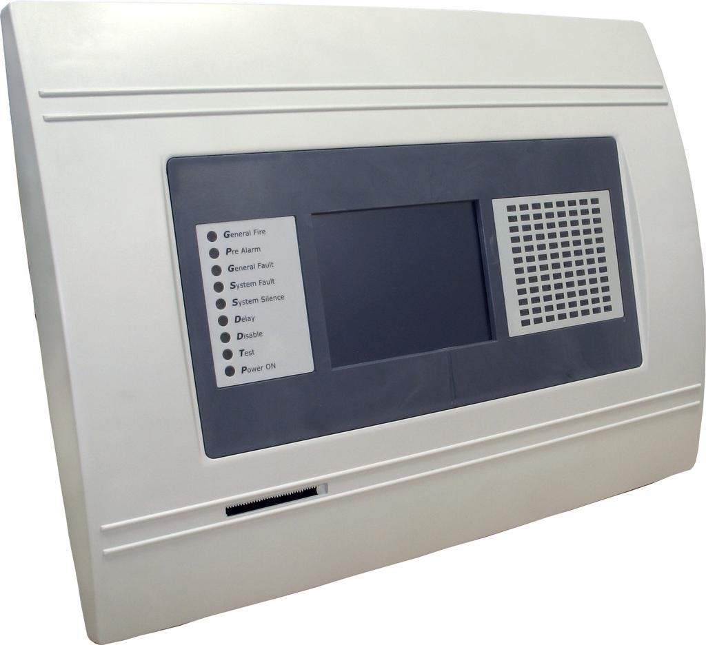
3 1. INTRODUCTION 1.1 General Description IRIS is an analogue addressable fire panel with maximum coverage of 96 zones, with 1 or 2 loops and 198 (99 detectors and 99 modules) devices per loop. The panel maintains a System Sensor series 200 protocol. An arbitrary number of devices can be added to each zone thus ensuring the easy adaptation of the system to any type of configuration. To avoid or significantly diminish problems when mounting the system it must be carefully planned prior to installation. This includes: establishing an address for every device and planning a name of maximum 40 digits (including the spaces) for each address, thereby ensuring easy access to the device. According to the acting standards for establishing fire systems and the plan of the building, the devices must be grouped in zones. Every loop provides for 99 (1-99) detectors and 99 (1-99) modules. General view of the IRIS Fire Panel 1.2 General Specifications The front panel consists of a graphic LCD display (dimensions 240x320) with a built-in touch screen and a light-emitting diode indication. Separate operator and engineer passwords provide access to the functions of the panel. The internal space of the box is protected with the help of secret screws. One or two loop expanders can be supplemented to the mother board. Each one can control up to 198 addressable devices (99 modules and 99 detectors). In a configuration with two loops, the panel covers 396 addressable devices. The system can be expanded by connecting several fire panels IRIS to the Ethernet, using TCP/IP for communication between them. The panel has a built-in real time clock and calendar, allowing day and night time modes of work. Switching over between the two modes can be automatic or manual. Events like FIRE, RESET, fault, etc., are saved in the memory, thereby creating an event log-file. It contains the time and date, the address of the device, the type (module or detector), the name of the device, the zone, the name of the zone, etc. Fire Panel IRIS - Installation Manual 3
4 1.2.1 General Technical Specifications Loops - 1 or 2 loop versions as standard Up to 99 detectors and 99 modules per loop Zones - 96 displayed zones Inputs - 4 programmable for volt-free Normal Open contact Monitored relay outputs 4 (Sounder, Fire, Fault and Fire Protection) Non monitored relay outputs 4 programmable, 230V/ 10A Display 320x240 CSTN graphic display (118.8mm X 89.38mm) with a touch panel Real time clock Up to 128 programmable Inputs/Outputs per panel Comprehensive day/night mode facility Simple Windows graphical configuration utility via Ethernet or USB Simple Http monitoring utility Loop less panel option (repeater) Thermal printer (optional) Digital communicator (optional) Flush mounting enclosure Multi-language support Easy software update Absolutely compatible with the requirements of EN54-2/ Structure Maximum configuration: - Main PCB - Power Source - LED-indication - Main Board - 20 Relays Expander Module - 2 Loop Controllers - Modem - Heat Printer Minimum configuration: - Main PCB - Power Supply Environment - Ambient Temperature: -5 C up to +50 C - Relative Humidity: up to 95% (without condense) - Storage Temperature: -10 C up to +60 C - Weight (without the battery): 6kg Electrical Specifications Earth connection The earth connection has to be realized in accordance with the rules for the electrical safety with the total resistance in the circuit lower than 10Ω. It is mandatory to connect the main power supply cable to the middle input of the fire panel terminal - see Power Source. Main power supply In normal operating conditions the fire panel is powered from the mains voltage line. In case of mains voltage line loss the fire panel is equipped with one rechargable battery. The characteristics of the main power supply are as follows: - Mail Power Supply: ~230V ±10% - Frequency: 50/ 60Hz - Electrical output: 1A! ATTENTION: Do not instal the fire panel near power electromagnetic fields (radio equipments, electric motors, etc.)! 4 Fire Panel IRIS - Installation Manual
5 Battery Power Supply - Voltage output: Ucharge=13,8V - Current output: Imax: 2A - Number of the Batteries: 1, 12v/ 18Ah - Battery Size: 167x181x76mm - Type of the Battery connection: with a flat terminal lug - Ø5mm (M5) List of the fuses - General Power Supply: 2A, Slow Type - Outputs: Sounder, Fire, Fault and Fire Protection - 0,5A, Self-recovering Type - Battery: 10A, Automobile Type List of the additional components, included in the set of the fire panel IRIS: 1. Fuse, Automobile Type, 10A Fuse 2A, Slow Type, for the Power Supply Balansing resistors, 10K Plastic taps Cable bandages Special Tool for unscrewing the secret bolts - 1! The panel should be installed by qualified specialists only. The electronic components of the panel are vulnerable to electrostatic discharge. Never add or turn off components which are being power supplied. Fire Panel IRIS - Installation Manual 5
6 2. INSTALLATION 2.1 Mounting The panel must be installed in a clean dry place and must not be subjected to impact orvibrations (Figure 1). It must be situated far form heating appliances. The temperature must be within 5ºС and + 50ºC. The fire panel is not water-proof! Unscrew the two secret bolts situated from above and from bellow the metal box with the help of the Special Tool in the set - see Figure 2. Remove the front panel as first disconnect the flat-cable for panel indication. After that unscrew the hinge bolts on the side of the front panel - Figure 3. (Note: You can unscrew and the hinge bolts on the side of the metal box. The special here is the presence of two plastic pads situated under the hinges. The pads have to be returned back under the hinges at closing the front pane.) Choose inlets for the cables, and put from the ptastic taps on those ones which you will not use. Figure 1 Figure 2 Figure Wall Mounting Use the templete in the set to fix the mounting holes of the metal box on the wall - see Figure 4. Drill holes (Ø6-8mm) on the wall and fix the metal box - see Fig 5. Route the external cables onto the back box, make off connection glands etc., BUT DO NOT make any connections at this stage. ENTER THE MAINS CA- BLE THROUGH ITS OWN CABLE ENTRY POINT AND KEEP MAINS WIRING AWAY FROM SYS- TEM AND OTHER LOW VOLTAGE WIRING. Connect the mains supply and earth to the main terminal block BUT DO NOT apply the main electrical supply at this stage. Position the accumulator battery in an upright position and fix the metal clamp. Figure 4 Figure 5 6 Fire Panel IRIS - Installation Manual
7 2.1.2 Flush Mounting Analogue-addressable fire panel IRIS is provided for flush mounting. In the set of the panel are included two special hinges used for building-in the metal box of the panel in gypsum plaster walls with thickness up to 25mm. Use given on Figure 6 dimentions to outline and to cut the mounting hole in the gypsum plaster wall. Fix the hinges on the back side of the gypsum plaster wall with suitable bolts, as shown on Figure 7, Position 1. Route the external cables onto the back box, make off connection glands etc., BUT DO NOT make any connections at this stage. ENTER THE MAINS CABLE THROUGH ITS OWN CABLE ENTRY POINT AND KEEP MAINS WIRING AWAY FROM SYSTEM AND OTHER LOW VOLTAGE WIRING. Place the metal box in the mounting hole and fix it with suitable bolts - Figure 7, Position 2. Connect the mains supply and earth to the main terminal block BUT DO NOT apply the main electrical supply at this stage. Position the accumulator battery in an upright position and fix the metal clamp. Figure 6. Dimentions of the metal box and the mountig hole. Figure 7. Action secuence for flush mounting. Figure 8. Flush mounting holes. Main view of the fix to the wall hinge and the bolts supporting the metal box. Fire Panel IRIS - Installation Manual 7
8 2.2 System components Front panel LED-indication of the events provides following functions: 1 - GENERAL FIRE 2 - PREALARM 3 - GENERAL FAULT 4 - SYSTEM FAULT 5 - SYSTEM SILENCE 6 - DELAY 7 - DISABLE 8 - TEST 9 - POWER ON Figure 9. Main view of the front panel Configuration of the basic modules Figure 10. Configuration of the basic modules in the system. 1 - Metal Clamp for supporting the accumulator battery. 2 - Terminal for connection between the accumulator battery and the main power source. An automobile type fuse 10A is situated into the terminal. 3 - Clamp for supporting the main power supply cable. 4 - Terminal for connection between the mains power supply and the power source. A slow type fuse 12A is situated into the terminal. 5 - Earthing lead. 8 Fire Panel IRIS - Installation Manual
9 2.2.3 Main Board The Main Board (Figure 11) is a basic part of the fire panel IRIS. Its function is to control the output devices sounders, fire detectors, signaling devices, etc. The Main Board could not work independently. Figure 11 General view of the Main Board of the fire panel. REL1, REL2, REL3 and REL4 Programmable outputs, 230V / 10A; +24V and +12V DC power supply terminals; GND Common earth IN1, IN2, IN3 and IN4 Inputs (Each input is independent from the others); SOUNDER Monitored output for connecting of a sounder, 24 VDC / 0,5 A; FIRE, FIRE PROTECTION and FAULT Monitored outputs for connecting of different devices (e.g. signaling devices), 24V / 0,5A; 1 - Flat-cable interface connector for front panel power supply; 2 - Flat-cable interface connectors for connecting 20 Relay Expander Module; (At connecting 20 Relay Expander Module to the system configuration, the total number of the programmable outputs increases to 24.) 3 - Flat-cable interface connector for connecting 20 Relay Expander Module; 4 - Fuse 0,5A, type Self-recovering; 5 - Mounting holes. Fire Panel IRIS - Installation Manual 9
10 IMPORTANT: The relay of the respective programmable output only breaks the circuit (NC: The left terminal lead) or closes the circuit (NO: The right terminal lead) according to the middle lead of each terminal. The relays of the programmable outputs just open or close the output circuit there is no difference in the potentials between the separate terminal leads! At the monitored outputs Sounder, Fire Protection, Fire and Fault could be measured 24 VDC and maximum output current 0,5A at closed relay contacts, ad 0V at open relay contacts. Figure 12 Example for connecting a button to inputs IN1 and IN2. ATTENTION: The active level of the input signal is logical zero! To the monitored output Sounder could be connected several sounders Figure 13. The maximum number of sounders that could be connected in the circuit, depends on their total current consumption, which must not exceed 0,5A. Before connecting the last sounder in the circuit, parallel to it must be added end-of-line resistor 10k. Figure 13. Connecting of sounders. 10 Fire Panel IRIS - Installation Manual
11 Relay Expander Module 20 Relay Expander Module (Figure 14.) is an additional module by which the total number of the programmable outputs increases to 24. The expander consists of 20 relays, controlling 20 separate outputs (110V / 1A) numbered REL5 REL24. The function of the relays is just to open or close the output circuit according to their configuration (the position of the jumper). It is possible the relay of the respective programmable output to open the circuit (NC: the left terminal lead) or to close it (NO: the right terminal lead) according to the middle lead of each terminal. Figure 14. General view of 20 Relay Expander Module. REL5 REL24 Programmable outputs, 110V / 1A; NC - Normally closed contact; NO - Normally open contact; 1 - Flat interface connectors for connecting 20 Relay expander module to the Main board; 2 - Jumper leads for programming the function of the respective relay to open (NC) or to close (NO) the circuit; 3 - Mounting holes for fixing the 20 Relay expander module to the Main board. Adding of 20 Relay Expander Module to the Main Board of the fire panel Figure Place the mounting clips into the pointed holes, as shown on Figure Screw the mounting supports into the pointed holes, as shown on Figure Place 20 Relay expander module on the Main board, thus the flat interface connectors on the both PCBs to connect to each other. 4 Fix with suitable bolts 20 Relay expander module to the Main Board. Fire Panel IRIS - Installation Manual 11
12 2.2.5 Loop Expander The Loop Expander (Figure 16) realizes the connection between the Main Board and devices connected to the communication line. The Loop Expander has two basic functions: 1. Gathers data from the devices in the communication line and transfers it to the Main Board. 2. Receives commands from the Main Board and transfers them to the devices connected in the communication line. In the configuration of analogue-addressable fire panel IRIS could be mounted two loop expanders, and thus the maximum number of the addressable devices increases to 396. To each loop expander could be connected up to 99 modules and 99 sensors. The maximum current consumption of the devices in the communication line is Imax = 700mA. If the consumption exceeds this value an over-load protection would be turned on. 1 Flat interface connector for connecting the Loop expander to the Main Board. 2 Flat interface connector for connecting second loop expander. Figure 16. General view of Loop Expander and an example for connecting devices to it. Adding of second loop expander in the configuration of the fire panel IRIS 1 Connect the flat interface connectors of the first and the second loop expanders. 2 Fix the second loop expander with suitable bolts to the metal box of the fire panel. Figure 17. Connecting of a second loop expander in the fire panel configuration. 12 Fire Panel IRIS - Installation Manual
13 2.2.6 Maximum permissible cable length The maximum length of the loop in the system could vary according to the cross-section and the ohmic resistance of the used cable. To make possible identifying devices with identical addresses (double addresses) in the system configuration, the cable resistance should not exceed definite calculated value. According to the ohmic cable resistance, calculate: Formula 1: L C1MAX = 21 / R C Formula 2: L C2MAX = 80 / R C, Where: L C1MAX and L C2MAX - are maximum permissible length of the used cabel, [km]; R C - is total ohmic resistance of the two wires of the used able; its value shows the magnitude of the cable resistance at length 1km [Ω/km]. If L C is the necessary length of the cable used in the loop, then: At L C L C1MAX - the fire pane will be able to communicate with the devices in the circuit and also will be able to identify the presence of double address. At L C1MAX < L C L C2MAX - the fire panel will be able to communicate with the devices in the circuit but will not be able to identify the presence of double addresses. At L C > L C2MAX - the fire panel will not be able neither to communicate with the devices nor to identify the presence of double addresses. Example: R C = 39 Ω/km, then L C1MAX = 21 / RC = 21 / 39 0,540km L C2MAX = 80 / RC = 80 / 39 2km L C = 1km In this case it is possible to use the chosen cable in the system, but the fire panel will not be able to identify devices with double addresses. If this could not satisfying the requirements of the system it must be chosen cable with lower ohmic resistance RC. The connection diagram shown on Figure 18, gives the possibility to protect devices against opening and short-circuit. For example, short-circuit in section 2 will not influence the operation of sections 1 and 3. The isolator modules at the both ends of section 2 will isolate it, and section 1 and 3 will continue working properly, as section 1 will operate by supply from the channel A and section 3 by supply from channel B. Since the fire panel will not be able to communicate with the devices from section 2, it will generate an alarm signal for lost devices and open circuit. Figure 18. IMPORTANT: The maximum number of devices between two isolator modules is 30! Fire Panel IRIS - Installation Manual 13
14 2.2.7 Main Power Source Figure 19. General view of the power source and the terminal. LED-indication of the power source LED Function Description 1 AC LOSS Main power supply loss. 2 Charger Fault Problem with the battery charging. 3 BATT LOSS Battery loss. 4 BATT Low Discharged battery. 5 EARTH FAULT Earth connection 10kΩ. 6 Rx / Tx Shows the communication with the panel. Terminal Block for connecting to external power supply. Terminal Function Description 1 GND Input for connectin of external power supply EARTH. 2 FAULT OUT Fault output, turns on when a problem with the main power supply occurred. Connect it to the input (Fault In) of the external power supply. 3 FAULT IN Input for connecting the Fault output of the external power supply V External power supply input.! Before the mains supply is switched on, check the correct connection of each loop, sounder or any other input or output. 14 Fire Panel IRIS - Installation Manual
15 2.2.8 Connecting of the accumulator battery Figure 20. Connecting the accumulator battery to the main power source. Connect the red cable to the positive pole of the battery, the black cable to the negative battery pole. Both of the cables are connected to the battery by means of a flat terminal lug Ø5mm. Connect the cable with the built-in thermo resistor to the negative battery pole. Check the presence and proper working of the automobile fuse 10A, situated in the terminal for connection between the battery and the power source.! Important: Never cut or shorten the cable with the built-in thermo resistor! That will cause harm to the normal charging process of the battery! ATTENTION: The connection between the accumulator battery and the main power source has some special features. It is strongly recommended to use only battery with electrical characteristics and dimensions pointed from the manufacturer. Before connecting to the power source check the polarity of the battery. The battery cannot power up the panel before the mains supply has been switched on. Connect the battery after the mains supply is turned on. If the battery is new it will take a few hours before its complete charging! The charging of the accumulator battery is done at maximum current Imax = 2A and charging voltage Ucharge < 13,8V. The charging of the battery depends on its temperature. The temperature is monitored by means of a thermo-resistor build-in the black cable without flat terminal lug at the end Figure 20. Never cut or shorten the cable with the built-in thermo resistor, because that will harm the normal charging of the battery! Fire Panel IRIS - Installation Manual 15

16 2.3. Network connection diagram It is possible to connect some individual IRIS fire panels in a network by means of a HUB and TCP/IP protocol Figure 21. A supervisor PC, which could follow the current status of the individual fire panels, monitors the current panel state. As an option, it is possible connecting of a modem, which allows connecting of the supervisor PC with other remote devices (in other cities, countries, etc.). Figure Fire Panel IRIS - Installation Manual
17 3. PROGRAMMING When turned on, the panel always conducts a procedure of loading the parameters, which usually takes about 30 sec. There is no access to the menus of the panel during that procedure. Upon the initial start up, the panel does not hold any configurations. Initialization may take several minutes. The initialization time needed depends on the number of periphery and loop devices. After the panel has been turned on, it performs a procedure for detecting newly installed periphery and loop devices. The general view of the CONFIGURATION Menu of IRIS Fire Panel is shown on Fig. Screen 1. It gives the installer the possibility to choose the type of the operation, which is necessary to do: 1. To program system parameters Programming Menu. 2. To study the panel operation, as to enter different parameters for the maintenance of the system Maintenance Menu. Fig. Screen Programming Menu To enter in the Programming Menu the installer has to choose button Programming. The general view of the menu is shown on Fig. Screen 2. Fig. Screen 2. On the left side of the screen are located buttons for entering submenus for parameter programming of Devices, Zones, Inputs, Outputs and Access Codes. To enter a desired submenu just choose it button. Choosing the button Restore Defaults on the left side of the screen can restore all the factory settings. Button Save is for quick saving of the entered information. With the button Exit in the bottom left corner the user/installer can easy move one step back on the previous screen. Fire Panel IRIS - Installation Manual 17

 - 4 input/ 4 monitored outputs/ 4 relays IO24 (Main Board + 20 Relay Expander Module) - 4 input/ 4 monitored outputs/ 24")
18 3.2 Devices In the addressable fire panel IRIS are supported periphery and loop devices. With choosing the Device button the user/installer enters a menu for choosing the type of the device Fig. Screen 3. Fig. Screen Periphery Devices Choosing Periphery Device button leads to submenu for entering the parameters of the available periphery devices in the system configuration Fig. Screen 4. List of 1.0 version supported periphery devices: PSU140 Power source IO4 (Main Board) - 4 input/ 4 monitored outputs/ 4 relays IO24 (Main Board + 20 Relay Expander Module) - 4 input/ 4 monitored outputs/ 24 relays LOOP1 (First Loop expander) / LOOP2 (Second Loop expander) Upon detecting a new periphery device (which is missing in the configuration), the following message will be displayed: NEW PERIPHERY DEVICES FOUND, and the number of the detected devices will be indicated. All new periphery devices have to be added to the panel configuration using the SAVE command for the specific device or the general SAVE command from the CONFIGURATION menu Fig. Screen 2. Any devices, not configured in the panel, shall not generate any messages. Where a periphery device is removed, the panel shall display PERIPHERY DEVICE FAULT. In the case of an unregistered device, the panel reduces the number of new devices, and if their number is 0 it will stop displaying the NEW PERIPHERY DEVICES FOUND notice. The device can be deleted from the configuration of the panel with the REMOVE command for the specific device. Where a device of a different type is placed in position on the panel of a given device from the configuration, the panel shall display PERIPHERY DEVICE TYPE ERROR. In order to replace a previous device with a new type, choose the REPLACE button for the specific device. Fig. Screen Fire Panel IRIS - Installation Manual

, where it is possible to follow the current information for the main and additional power")
19 Physical Address of Periphery Device The panel is able to operate with up to 5 periphery devices, addressed 1 to 5. The devices can be self-addressed, whereby the first along the link acquires the lowest address. The power supply always acquires address Button for Entering the Device Submenu There is a menu for each periphery device which displays its current configuration and parameters. On Fig. Screen 5 is shown the submenu of the first periphery device in the panel configuration (Power source PSU), where it is possible to follow the current information for the main and additional power supply. On Fig. Screen 6 is shown the submenu of the second device in the system configuration (Main board I/O4, or Main board + 20 Relay Expander I/O24), and on Fig. Screen 7 the third available periphery device (First Loop expander LOOP1). Fig. Screen 5 PSU (Power source) Fig. Screen 6 I/O24 (Main board + 20 Relay Expander Module) Fire Panel IRIS - Installation Manual 19

20 Fig. Screen 7 LOOP1 (First Loop expander) Current Status of the Device The running status of the device can be: NORMAL the device is properly operating. NEW the device is new to the system. It must be saved. FAULT the device does not respond. TYPE ERROR a device, different from that saved, has been detected. EMPTY no device has been detected at this address Loop Devices The device searches for new loop devices only when the respective loop controller has been added to the configuration. To enter the submenu for programming of the loop devices parameters from Device menu choose button Loop Devices Fig. Screen 3. When a new loop device is found (missing in the configuration) the message NEW LOOP DEVICES FOUND will be generated, as well as the number of detected devices. The message is generated by loops. Adding a new device to the configuration is accomplished with the APPLY command from the specific device menu or with the help of the general SAVE command from the Programming menu. Any device, which has not been added to the configuration, cannot generate messages. In case of removal of a loop device, the panel generates a LOOP DEVICE FAULT message. When a newly detected device is removed, the panel reduces the number of the new devices and if their number is 0 it shall extinguish the NEW LOOP DEVICES FOUND message. Removing the device from the configuration is accomplished with the REMOVE command in the menu for the specific device. Where in abundance, it is possible for device addresses to double along the loops (see also Maximum permissible cable length). In such cases the message DOUBLE ADDRESS will be displayed along with the problem address. Should a different device type appear at the address of a saved device, the panel will generate LOOP DEVICE TYPE ERROR. The new device can be saved by selecting the correct type from the menu of types and the APPLY command in the menu for the specific device. The panel cannot distinguish the types of devices in one and the same area. This requires each type of device to be further defined by the installer. For ease of introduction, the panel suggests possible devices for selection. Information for correspondence of the device types is given in Maintained Loop Devices and Appendix B Tables for correspondence of the device types. 20 Fire Panel IRIS - Installation Manual
21 The SAVE button can be used for fast configuration of the device. Following this command, the panel sets up all detected loop and periphery devices by default. New devices only are configured under this command. The RESTORE DEFAULTS command deletes all system parameters. On Fig. Screen 8 is given the general view of the submenu for new loop devices configuration. Fig. Screen Confirm Change Button Saves changes in the permanent memory Button to enable/disable a device See Module or detector selection button This button is used to switch over between module and detector addresses Address Navigation Button This button helps to screen (in sequence or directly) the devices of one and the same loop Loop Number Navigation Button These keys alternate the loop (in sequence or directly) of the screened devices Zone Selection Button These keys alternate the zone (in sequence or directly) to which the device belongs Current Device Status The current device status varies according to the device type Button for Changing the Current Status of the Device The action of this button depends on the type of current status of the device. The following are possible: REMOVE deletes the device from the configuration. SAVE saves the new device in the configuration. REPLACE replaces the device type Change Device Type Button Press this button for the panel to provide a compatibility device list of which to choose the most suitable one. The SELECT NEW DEVICE TYPE message will be portrayed Fig. Screen 9. Fire Panel IRIS - Installation Manual 21


22 Active Field for Text Introduction Choosing this field accesses the text introduction mode. The text must not exceed 40 digits together with the spaces Fig. Screen 10. Entered information is confirmed with button. Figure Screen 9. Figure Screen Additional Settings Button The additional adjustments vary according to the type of device. Setting the day and nighttime mode, as and setting the levels of the alarm signal (FIRE) Fig. Screen 11, is performed by pressing of the respective button and entering of the desired value by means of an additional keypad displayed on the screen. Fig. Screen Fire Panel IRIS - Installation Manual
23 Maintained Loop devices (See also APPENDIX B: Tables for corresponding of device types) E (Ionization sensor) - Following the initial start-up of the system there is no need for further readjustment of the type. - A number should be set for the zone (1-96), to which the messages from the specific device will be sent, indicating: ALARM, TROUBLE, etc. - A specific mode is assigned to the light-emitting diode of the device: BLINK and OFF. In the BLINK mode the LED blinks at every query addressed by the system. In the OFF mode the LED does not reflect any device contact. The LED turns ON in case of a FIRE signal. - Introduce the name of the device 40 digits. - The device maintains day and nighttime working modes. Each of these are assigned different times of filtration of the FIRE signal. The nighttime mode must be less than that of the daytime mode. For specific cases the times of both modes can be 0, disallowing filtration time, having the fire signal is immediately perceived. The device maintains day and nighttime working modes. Both are assigned different thresholds for FIRE (1-3). Nighttime mode must be of a lower threshold than that of the daytime one. It is possible to experiment with various alarm levels EM (Photoelectric Smoke sensor) - Following the initial start-up of the system there is no need for further readjustment of the type. - A number should be set for the zone (1-96), to which the messages from the specific device will be sent, indicating: ALARM, TROUBLE, etc. - A specific mode is assigned to the light-emitting diode of the device: BLINK and OFF. In the BLINK mode the LED blinks at every query addressed by the system. In the OFF mode the LED does not reflect any device contact. The LED turns ON in case of a FIRE signal. - Introduce the name of the device 40 digits. - The device maintains day and nighttime working modes. Each of these are assigned different times of filtration of the FIRE signal. The nighttime mode must be less than that of the daytime mode. For specific cases the times of both modes can be 0, disallowing filtration time, having the fire signal is immediately perceived. The device maintains day and nighttime working modes. Both are assigned different thresholds for FIRE (1-3). Nighttime mode must be of a lower threshold than that of the daytime one. It is possible to experiment with various alarm levels EIS (Photoelectric Smoke sensor) - After the initial starting up of the system the type needs to be fine-tuned. The panel shall detect devices like 2251ЕМ. From the menu of types select the correct type of the respective device (this is recommended in order to ensure the proper performance of the device). - A number should be set for the zone (1-96), to which the messages from the specific device will be sent, indicating: ALARM, TROUBLE, etc. - A specific mode is assigned to the light-emitting diode of the device: BLINK and OFF. In the BLINK mode the LED blinks at every query addressed by the system. In the OFF mode the LED does not reflect any device contact. The LED turns ON in case of a FIRE signal. - Introduce the name of the device 40 digits. - The device maintains day and nighttime working modes. Each of these are assigned different times of filtration of the FIRE signal. The nighttime mode must be less than that of the daytime mode. For specific cases the times of both modes can be 0, disallowing filtration time, having the fire signal is immediately perceived (Smoke beam sensor) - After the initial starting up of the system the type needs to be fine-tuned. The panel shall detect devices like 2251ЕМ. From the menu of types select the correct type of the respective device (this is recommended in order to ensure the proper performance of the device). - A number should be set for the zone (1-96), to which the messages from the specific device will be sent, indicating: ALARM, TROUBLE, etc. - A specific mode is assigned to the light-emitting diode of the device: BLINK and OFF. In the BLINK mode the LED blinks at every query addressed by the system. In the OFF mode the LED does not reflect any device contact. The LED turns ON in case of a FIRE signal. - Introduce the name of the device 40 digits. Fire Panel IRIS - Installation Manual 23
24 - The device maintains day and nighttime working modes. Each of these are assigned different times of filtration of the FIRE signal. The nighttime mode must be less than that of the daytime mode. For specific cases the times of both modes can be 0, disallowing filtration time, having the fire signal is immediately perceived FTX-P1 (Photoelectric Smoke sensor) - After the initial starting up of the system the type needs to be fine-tuned. The panel shall detect devices like 2251ЕМ. From the menu of types select the correct type of the respective device (this is recommended in order to ensure the proper performance of the device). - A number should be set for the zone (1-96), to which the messages from the specific device will be sent, indicating: ALARM, TROUBLE, etc. - A specific mode is assigned to the light-emitting diode of the device: BLINK and OFF. In the BLINK mode the LED blinks at every query addressed by the system. In the OFF mode the LED does not reflect any device contact. The LED turns ON in case of a FIRE signal. - Introduce the name of the device 40 digits. - The device maintains day and nighttime working modes. Each of these are assigned different times of filtration of the FIRE signal. The nighttime mode must be less than that of the daytime mode. For specific cases the times of both modes can be 0, disallowing filtration time, having the fire signal is immediately perceived (Linear smoke sensor) - After the initial starting up of the system the type needs to be fine-tuned. The panel shall detect devices like 2251ЕМ. From the menu of types select the correct type of the respective device (this is recommended in order to ensure the proper performance of the device). - A number should be set for the zone (1-96), to which the messages from the specific device will be sent, indicating: ALARM, TROUBLE, etc. - A specific mode is assigned to the light-emitting diode of the device: BLINK and OFF. In the BLINK mode the LED blinks at every query addressed by the system. In the OFF mode the LED does not reflect any device contact. The LED turns ON in case of a FIRE signal. - Introduce the name of the device 40 digits. - The device maintains day and nighttime working modes. Each of these are assigned different times of filtration of the FIRE signal. The nighttime mode must be less than that of the daytime mode. For specific cases the times of both modes can be 0, disallowing filtration time, having the fire signal is immediately perceived. - The device can be tested by covering the reflector, depending on the selected alarm level. As a result a FIRE signal is generated to the respective zone. In the case of complete blockage of the reflector a BEAM BLOCKAGE message is generated. If there are any reflective objects in the path of the detector a SIGNAL OVER RANGE message is generated EM (Temperature sensor) - Following the initial start-up of the system there is no need for further readjustment of the type. - A number should be set for the zone (1-96), to which the messages from the specific device will be sent, indicating: ALARM, TROUBLE, etc. - A specific mode is assigned to the light-emitting diode of the device: BLINK and OFF. In the BLINK mode the LED blinks at every query addressed by the system. In the OFF mode the LED does not reflect any device contact. The LED turns ON in case of a FIRE signal. - Introduce the name of the device 40 digits. - The device maintains day and nighttime working modes. Each of these are assigned different times of filtration of the FIRE signal. The nighttime mode must be less than that of the daytime mode. For specific cases the times of both modes can be 0, disallowing filtration time, having the fire signal is immediately perceived TEM (Temperature sensor) - After the initial starting up of the system the type needs to be fine-tuned. The panel shall detect devices like 5251ЕМ. From the menu of types select the correct type of the respective device (this is recommended in order to ensure the proper performance of the device). - A number should be set for the zone (1-96), to which the messages from the specific device will be sent, indicating: ALARM, TROUBLE, etc. - A specific mode is assigned to the light-emitting diode of the device: BLINK and OFF. In the BLINK mode the LED blinks at every query addressed by the system. In the OFF mode the LED does not reflect any device contact. The LED turns ON in case of a FIRE signal. - Introduce the name of the device 40 digits. 24 Fire Panel IRIS - Installation Manual
25 - The device maintains day and nighttime working modes. Each of these are assigned different times of filtration of the FIRE signal. The nighttime mode must be less than that of the daytime mode. For specific cases the times of both modes can be 0, disallowing filtration time, having the fire signal is immediately perceived HTEM (Temperature sensor) - After the initial starting up of the system the type needs to be fine-tuned. The panel shall detect devices like 5251ЕМ. From the menu of types select the correct type of the respective device (this is recommended in order to ensure the proper performance of the device). - A number should be set for the zone (1-96), to which the messages from the specific device will be sent, indicating: ALARM, TROUBLE, etc. - A specific mode is assigned to the light-emitting diode of the device: BLINK and OFF. In the BLINK mode the LED blinks at every query addressed by the system. In the OFF mode the LED does not reflect any device contact. The LED turns ON in case of a FIRE signal. - Introduce the name of the device 40 digits. - The device maintains day and nighttime working modes. Each of these are assigned different times of filtration of the FIRE signal. The nighttime mode must be less than that of the daytime mode. For specific cases the times of both modes can be 0, disallowing filtration time, having the fire signal is immediately perceived TEM (Multi-criteria fire sensor) - Following the initial start-up of the system there is no need for further readjustment of the type. - A number should be set for the zone (1-96), to which the messages from the specific device will be sent, indicating: ALARM, TROUBLE, etc. - A specific mode is assigned to the light-emitting diode of the device: BLINK and OFF. In the BLINK mode the LED blinks at every query addressed by the system. In the OFF mode the LED does not reflect any device contact. The LED turns ON in case of a FIRE signal. - Introduce the name of the device 40 digits. - The device maintains day and nighttime working modes. Both are assigned different thresholds for FIRE (1-6). Threshold 6 responds to an alarm signal sent from a thermal detector. It is recommended that threshold 6 be selected for daytime mode. Nighttime mode must be of a lower threshold than that of the daytime one. It is possible to experiment with various alarm levels. The day and nighttime working modes are assigned different times of filtration of the FIRE signal. The nighttime mode must be less than that of the daytime mode. For specific cases the times of both modes can be 0, disallowing filtration time, having the fire signal is immediately perceived (Photoelectric smoke sensor) - Following the initial start-up of the system there is no need for further readjustment of the type. - A number should be set for the zone (1-96), to which the messages from the specific device will be sent, indicating: ALARM, TROUBLE, etc. - A specific mode is assigned to the light-emitting diode of the device: BLINK and OFF. In the BLINK mode the LED blinks at every query addressed by the system. In the OFF mode the LED does not reflect any device contact. The LED turns ON in case of a FIRE signal. - Introduce the name of the device 40 digits. - The device maintains day and nighttime working modes. Both are assigned different thresholds for FIRE (1-9). Nighttime mode must be of a lower threshold than that of the daytime one. It is possible to experiment with various alarm levels. The day and nighttime working modes are assigned different times of filtration of the FIRE signal. The nighttime mode must be less than that of the daytime mode. For specific cases the times of both modes can be 0, disallowing filtration time, having the fire signal is immediately perceived M210E (Single input) - Following the initial start-up of the system there is no need for further readjustment of the type. - A number should be set for the zone (1-96), to which the messages from the specific device will be sent, indicating: ALARM, TROUBLE, etc. - A specific mode is assigned to the light-emitting diode of the device: BLINK and OFF. In the BLINK mode the LED blinks at every query addressed by the system. In the OFF mode the LED does not reflect any device contact. The LED turns ON in case of activation at the input. - Introduce the name of the device 40 digits. Fire Panel IRIS - Installation Manual 25
26 M220E (Dual input) - After the initial starting up of the system the type needs to be fine tuned. The panel shall detect devices like М210E. From the menu of types select the correct type of the respective device (this is recommended in order to ensure the proper performance of the device). - A number should be set for the zone (1-96), to which the messages from the specific device will be sent, indicating: ALARM, TROUBLE, etc. - A specific mode is assigned to the light-emitting diode of the device: BLINK and OFF. In the BLINK mode the LED blinks at every query addressed by the system. In the OFF mode the LED does not reflect any device contact. The LED turns ON in case of activation at the input. - Introduce the name of the device 40 digits M221EINPUT (Input) - After the initial starting up of the system the type needs to be fine-tuned. The panel shall detect devices like М210E. From the menu of types select the correct type of the respective device (this is recommended in order to ensure the proper performance of the device). - A number should be set for the zone (1-96), to which the messages from the specific device will be sent, indicating: ALARM, TROUBLE, etc. - A specific mode is assigned to the light-emitting diode of the device: BLINK and OFF. In the BLINK mode the LED blinks at every query addressed by the system. In the OFF mode the LED does not reflect any device contact. The LED turns ON in case of activation at the input. - Introduce the name of the device 40 digits M221EOUTPUT (output) - After the initial starting up of the system the type needs to be fine tuned. The panel shall detect devices like М210E. From the menu of types select the correct type of the respective device (this is recommended in order to ensure the proper performance of the device). - A number should be set for the zone (1-96), to which the messages from the specific device will be sent, indicating: ALARM, TROUBLE, etc. - A specific mode is assigned to the light-emitting diode of the device: BLINK and OFF. In the BLINK mode the LED blinks at every query addressed by the system. In the OFF mode the LED does not reflect any device contact. The LED turns ON in case of activation at the output. - Introduce the name of the device 40 digits M201E (Main switch output) - Following the initial start-up of the system there is no need for further readjustment of the type. - A number should be set for the zone (1-96), to which the messages from the specific device will be sent, indicating: ALARM, TROUBLE, etc. - A specific mode is assigned to the light-emitting diode of the device: BLINK and OFF. In the BLINK mode the LED blinks at every query addressed by the system. In the OFF mode the LED does not reflect any device contact. The LED turns ON in case of activation at the input. - Introduce the name of the device 40 digits M501ME (Input) - After the initial starting up of the system the type needs to be fine tuned. The panel shall detect devices like М210E. From the menu of types select the correct type of the respective device (this is recommended in order to ensure the proper performance of the device). - A number should be set for the zone (1-96), to which the messages from the specific device will be sent, indicating: ALARM, TROUBLE, etc. - A specific mode is assigned to the light-emitting diode of the device: BLINK and OFF. In the BLINK mode the LED blinks at every query addressed by the system. In the OFF mode the LED does not reflect any device contact. The LED turns ON in case of activation at the input. - Introduce the name of the device 40 digits M503ME (Micro monitor) - After the initial starting up of the system the type needs to be fine-tuned. The panel shall detect devices like М210E. From the menu of types select the correct type of the respective device (this is recommended in order to ensure the proper performance of the device). - A number should be set for the zone (1-96), to which the messages from the specific device will be sent, indicating: ALARM, TROUBLE, etc. 26 Fire Panel IRIS - Installation Manual
27 - A specific mode is assigned to the light-emitting diode of the device: BLINK and OFF. In the BLINK mode the LED blinks at every query addressed by the system. In the OFF mode the LED does not reflect any device contact. The LED turns ON in case of activation at the input. - Introduce the name of the device 40 digits M500KAC (Call point) - After the initial starting up of the system the type needs to be fine tuned. The panel shall detect devices like М210E. From the menu of types select the correct type of the respective device (this is recommended in order to ensure the proper performance of the device). On a correct adjustment of the type, after activation of a Call Point is generated an alarm signal to the relevant device. - A number should be set for the zone (1-96), to which the messages from the specific device will be sent, indicating: ALARM, TROUBLE, etc. - A specific mode is assigned to the light-emitting diode of the device: BLINK and OFF. In the BLINK mode the LED blinks at every query addressed by the system. In the OFF mode the LED does not reflect any device contact. The LED turns ON in case of activation at the input. - Introduce the name of the device 40 digits M512ME (Zone monitor) - Following the initial start-up of the system there is no need for further readjustment of the type. - A number should be set for the zone (1-96), to which the messages from the specific device will be sent, indicating: ALARM, TROUBLE, etc. - A specific mode is assigned to the light-emitting diode of the device: BLINK and OFF. In the BLINK mode the LED blinks at every query addressed by the system. In the OFF mode the LED does not reflect any device contact. The LED turns ON in case of activation at the input. - Introduce the name of the device 40 digits EMA24 & DBS24 (Loop sounders) - After the initial starting up of the system the type needs to be fine tuned. The panel shall detect devices like М210E. From the menu of types select the correct type of the respective device (this is recommended in order to ensure the proper performance of the device). - A number should be set for the zone (1-96), to which the messages from the specific device will be sent, indicating: ALARM, TROUBLE, etc. - A specific mode is assigned to the light-emitting diode of the device: BLINK and OFF. In the BLINK mode the LED blinks at every query addressed by the system. In the OFF mode the LED does not reflect any device contact. The LED turns ON in case of activation at the output. - Introduce the name of the device 40 digits. Important: Every device can be enabled or disabled. When disabled a LOOP DEVICE DISA- BLED message is generated to the respective zone. No signals will be perceived from a disabled device. Device disabling does not terminate after a RESET command. Fire Panel IRIS - Installation Manual 27
28 3.3 Zones The IRIS analogue-programmable fire panel avails of 96 zones. There are separate LED-s to indicate FIRE and PREALARM statuses for each zone. In case of FIRE event - LED is permanently lit. In case of a PRE- ALARM event - LED blinks. To enter the submenu for zone configuration, chose Zones button from Programming menu Fig. Screen 2. The general view of the zone configuration menu is shown on Fig. Screen 12. Fig. Screen Button for Selecting the Zone Number The zone number can be selected in sequence or directly, which can than be monitored Active Field for Introducing Zone Name Choose the button to enter the screen (Fig Screen 10), for introducing the zone name, which shall not exceed 40 digits together with the spaces. Verify the information with the button Button for Zone Mode Change Each zone has two working modes: NORMAL and 2DEVICES. In NORMAL mode any detector activation within the system generates an alarm event to the respective zone. In 2DEVICES mode any detector activation within the system generates a PREALARM event to the respective zone, but also awaits the activation of another detector from the same zone to generate a FIRE signal. The RESET command shall disable the FIRE and PREALARM events Sounder Delay The delay can be within an interval of sec. In case of activation of more than one zone, the delays to the outputs are caused by the zone with shorter delays Fire output Delay The delay can be within an interval of sec. In case of activation of more than one zone, the delays to the outputs are caused by the zone with shorter delays Fire protection Output Delay The delay can be within an interval of sec. In case of activation of more than one zone, the delays to the outputs are caused by the zone with shorter delays Enable/Disable Zone Button See Fire Panel IRIS - Installation Manual
 INVERTED the output is set at ON, when the result of the logical function is OFF.")
29 3.4 Inputs To enter the submenu for inputs configuration choose Inputs button from Programming menu Fig. Screen 2. The general view of the menu for inputs configuration is shown on Fig. Screen 13. Fig. Screen 13 Menu for introducing input parameters Input delay Delays can be within sec Input Active Status (Polarity) INVERTED the output is set at ON, when the result of the logical function is OFF. NORMAL the output is set at ON, when the result of the logical function is ON Mode LATCHED deleted only after RESET. UNLATCHED monitors the status Type Selection Menu The 1.0 version types are: NONE PERIPHERY_DEVICE LOOP_DEVICE ZONE TIME DATE ACTION GENERAL NETWORK Parameter Selection Menu Depending on the type of input, the parameters can be: PERIPHERY_DEVICE Number of the periphery device and number of its input. LOOP_DEVICE Number of the loop, device address and indication whether it is a module or detector. Only a de vice with an input can be configured. ZONE Number of zone and event for activation. The possible events by zones are: - FIRE - FAULT - DISABLED - PREALARM Fire Panel IRIS - Installation Manual 29

30 TIME Device input. activation time. DATE Device input activation date. ACTION Device input activation action. The possible actions are as follows: - SILLENCE_BUZZER - SILLENCE_SOUNDER - RESET - SOUNDER_ON - FIRE_BRIGADE_ON - FAULT_ROUTING_ON - FIRE_PROTECTION_ON GENERAL General status which will activate the input of the device. The possible statuses can be: - COMMON _FIRE - COMMON_PREALARM - COMMON_FAULT - SYSTEM_FAULT - DISABLED - TEST NETWORK Panel number and output number, to which the input shall be attached. 3.5 Outputs To enter the submenu for outputs configuration choose Outputs button from Programming menu Fig. Screen 2. The general view of the menu for inputs configuration is shown on Fig. Screen 14. Fig. Screen 14 - Menu for introducing output parameters. 30 Fire Panel IRIS - Installation Manual

31 3.5.1 Type of output NONE PERIPHERY_DEVICE LOOP_DEVICE NETWORK Parameters Depending on the type of output, the parameters can be as follows: PERIPHERY_DEVICE The number of the periphery device and its output number. LOOP_DEVICE The number of the loop device, the device address and whether it concerns a module or a detec tor. It is possible to enter and only device, which is output. NETWORK Number of the panel and number of the input to which the output will be connected Output Delay This could be within sec Output Active Status (Polarity) INVERTED the output is set at ON, when the result of the logical function is OFF. NORMAL the output is set at ON, when the result of the logical function is ON Pulse Type CONTINUOUS the output signal is continuous PULSED the output signal is a pulse signal (3 sec./ 3 sec.) ONE PULSE the output signal is a single pulse signal (5 sec) ONE PULSE must be used in the case of ACTION type activating input or else the activating input must be LATCHED or the output LATCHED Menu for selection of the inputs, controlling the outputs Fig. Screen Mode LATCHED deleted only after RESET. UNLATCHED monitors the status. Fire Panel IRIS - Installation Manual 31
 and the level of access for the respective code Fig. Screen 16.")
32 3.6 Access Codes The access codes can be viewed and edited in the ACCESS CODES submenu, menu Programming see Fig. Screen 2. It displays in turn: the code number, the access code (symbolic sequence) and the level of access for the respective code Fig. Screen 16. Other codes can be viewed by scrolling the navigation arrows for changing the code number. Fig. Screen 16. By default the system has the following configuration of the access codes: Code number Code Access Level Accessible for programming are the fields Code and Access level. The ACCESS CODES menu is accessible only at access level Changing the Code To change the access code select the Button for introducing of access code button on the right of the field with the current code. The code introduction menu is automatically accessed. The code consists of 4 figures. After the code is initially entered, the system shall request the code to be entered again for verification. If the codes differ the system will ignore whatever was entered and the old code will remain active. If both codes are identical, the new code will be displayed in the ACCESS CODES output field and an Apply button will appear. Select Apply to save the entered code. If a code has already been entered the system will ignore it and will retain the old one Changing the Access Level Changing the level of access is done by choosing the Change button next to the field for calling out the access level. When activated a menu appears in which the user selects a new level of access (1-3) by pressing the respective button or EXIT to leave. If the newly assigned access level is different from the current one, the Apply button will be activated. Pressing that will save the new access level. There must be at least one code in the system with an access code 3! The program disallows editing a level of access (3) if it is the only one! 32 Fire Panel IRIS - Installation Manual


33 4. MAINTENANCE 4.1 Maintenance Menu To enter in the Maintenance Menu the installer has to choose button Maintenance Fig. Screen 1. The general view of the menu is shown on Fig. Screen 17. Fig. Screen Time introducing Choose the button Time from the Maintenance Menu to set the current time Fig. Screen 18. The desired time can be set with the buttons for selecting the hours, minutes and seconds. Fig. Screen Date introducing Choose the button Date from the Maintenance Menu to set the current date Fig. Screen 19. The desired date can be set with the buttons for selecting the day, month and year. Fig. Screen 19. Fire Panel IRIS - Installation Manual 33

 and the end hour and minutes (the time when the nighttime mode is activated) are introduced.")
34 4.4 Daytime Mode Choose the button Day from the Maintenance Menu to set the daytime schedule for detectors operation Fig. Screen 20. Fig. Screen 20 Fig. Screen 21 In this mode the detectors use the alarm level which has been programmed as day mode. This is usually a level of lower sensitivity. It lowers the risk of false alarms caused by dust, cigarette smoke, etc. Nighttime mode is opposite to the daytime mode (higher level of sensitivity). Daytime mode can be: ON, OFF or Schedule Fig. Screen 21. In Schedule mode the initial hour and minutes (the time when the daytime mode is activated) and the end hour and minutes (the time when the nighttime mode is activated) are introduced. The times are set for every day of the week. By default the station is in nighttime mode. 4.5 Output Delay Introduction Choose the button Output Delay from the Maintenance Menu to set the output delay Fig. Screen 22. Fig. Screen Fire Panel IRIS - Installation Manual

35 4.5.1 Sounder Delay Choose Sounder Delay button from Output Delay Menu Fig. Screen 22 to enter the submenu for sounder delay introduction Fig. Screen 23. A delay can be added before the sounders are turned on. This provides the possibility of checking the authenticity of the alarm before the sounders are turned on (an official visits the site of the fire and inspects for such). The delay can be: ON, OFF or Schedule Fig. Screen 21. In Schedule mode the initial hour and minutes (the time when the delay is activated) and the end hour and minutes (the time when the delay is deactivated) are introduced. The times are set for every day of the week. During turned on Delay the LED is active. Fig. Screen Fire output Delay Choose Fire Br. Delay button from Output Delay Menu Fig. Screen 22 to enter the submenu for fire output delay introduction (the screen is the same as those for sounder delay introduction). A delay can be added before the sounders are turned on (fire output). This provides the possibility of checking the authenticity of the alarm before the sounders are turned on (an official visits the site of the fire and inspects for such). The delay can be: ON, OFF or Schedule. In Schedule mode the initial hour and minutes (the time when the delay is activated) and the end hour and minutes (the time when the delay is deactivated) are introduced. The times are set for every day of the week. During turned on Delay the LED is active Fire Protection Delay Choose Fire Pr. Delay button from Output Delay Menu Fig. Screen 22 to enter the submenu for fire protection delay introduction (the screen is the same as those for sounder delay introduction). A delay can be added before the fire protection system is turned on. This provides the possibility of checking the authenticity of the alarm before the sounders are turned on (an official visits the site of the fire and inspects for such). The delay can be: ON, OFF or Schedule. In Schedule mode the initial hour and minutes (the time when the delay is activated) and the end hour and minutes (the time when the delay is deactivated) are introduced. The times are set for every day of the week. During turned on Delay the LED is active. Fire Panel IRIS - Installation Manual 35


36 4.6 LOG-file view Choose View Log from the Maintenance Menu to enter in a screen for viewing the happened events in the system. The addressable fire panel IRIS can show maximum 999 events, which could be viewed by date or number Fig. Screen 24. Fig. Screen Testing The addressable fire panel IRIS has an option for testing of zone functioning and the LED-indication of the panel. To make a test, choose the Test button from Programming Menu Fig. Screen 17. On the displayed screen the user/installer could choose which test to perform zone or LED-indication testing Fig. Screen 25. Fig. Screen 25. After choosing the desired test by pressing the respective button, the user/installer could examine the proper functioning of each zone and the LED-indication of the front panel. The entered information has to be confirmed by pressing Apply button. 36 Fire Panel IRIS - Installation Manual

37 4.8 Disable introducing The user/installer can enable or disable the loop devices, zones and the outputs of the fire panel. To introduce enabling or disabling a function you can directly choose the respective button and make corrections, or first by pressing View button to look at the current status of the system and after that, if it is necessary, to enter new data Fig. Screen 26. Fig. Screen Loop Devices Disabling The user/installer could first look at the current status of the loop devices by choosing View button situated next to the Loop devices button see Fig. Screen 26. On the screen of the panel is displayed the current status of the loop devices programmed earlier in the system (see part Programming, Loop Devices) Fig. Screen 27. Fig. Screen 27 From the screen for the current status of the loop devices the user/installer can introduce new settings as choose the button with the number of the respective device 1,2,3 40. With the buttons is possible to be viewed and the other loop devices in the configuration of the system, with number over 40. By choosing a button with a device number the user/installer moves to menu for setting of the parameters of the respective device see Fig. Screen 8, part Programming. Note: From the disabling menu you can directly enter in the loop devices configuration menu (Fig. Screen 8) as choose Loop Devices button (Fig. Screen 26). Fire Panel IRIS - Installation Manual 37
 Fig.")
38 4.8.2 Zone disabling The user/installer could first look at the current status of the loop devices by choosing View button situated next to the Zones button see Fig. Screen 26. On the screen of the panel is displayed the current status of the loop devices programmed earlier in the system (see part Programming, 3.3 Zones) Fig. Screen 28. Fig. Screen 28 From the screen for the current status of the zones the user/installer can introduce new settings as choose the button with the number of zone 1,2,3 50. With the buttons is possible to be viewed and the other zones in the configuration of the system, with number over 50. By choosing a button with a zone number the user/installer moves to menu for setting of the parameters of the respective zone see Fig. Screen 12, part Programming. Note: From the disabling menu you can directly enter in the zone configuration menu (Fig. Screen 12) as choose Zones button (Fig. Screen 26) Outputs disabling From the menu for disabling introduction Fig. Screen 26, the user/installer can disable or enable the monitored outputs of the IRIS fire panel Sounder, Fire Brigade, Fire Protection and Fire Routing Fig. Screen 29. Fig. Screen Software version By choosing Software Rev button from the general Maintenance Menu, in a separate screen you can see the last version of the used foftware. 38 Fire Panel IRIS - Installation Manual
!")
39 4.10 Calibrating the Display It is possible that after a certain period of use the parameters of the Touchscreen display may change, causing difficulties in marking the sites. This would require it to be calibrated periodically, which can be done in access levels 2 and 3. ATTENTION! Calibrating the display must be done with a Touch screen pen (or PALM)! To begin a display calibration procedure the following sequence of actions must be performed: Main menu Maintenance Calibration Coordinates The calibration of the display runs in the following 4 stages see also Fig. Screen The following message is displayed on the screen: Press the cross center in the top left corner of the screen: The user has to press the point on the top left corner of the display. It is marked with a cross and it is desirable to choose the crossing point of the two lines. The calibration procedure shall continue after the point is pressed. 2. The following message is displayed on the screen: Press the cross center in the top right corner of the screen: By analogy, the next point, which has to be pressed, is selected in the top right corner of the display, once again marked with a cross. The calibration procedure shall continue after the point is pressed. 3. The following message is displayed on the screen: Press the cross center in the botton right corner of the screen: This is the last point and is situated in the lower right corner of the display. The calibration procedure shall continue after the point is pressed. 4. The following message is displayed on the screen: Press a point within the rectangle in the top left corner of the screen: This is the menu for verifying input data, and it is entered automatically. The user has to press the rectangular field with the pen in the upper left corner of the display. The message Calibration Successful!!! will be displayed if the calibration has been successful and after pressing of any part of the display, the programme returns to the main menu. The message Calibration Unsuccessful!!! will be displayed if the calibration has been unsuccessful, the newly introduced data will be ignored and after pressing of any part of the display, the program returns to the main menu. Fig. Screen 30. Fire Panel IRIS - Installation Manual 39
, the status of the fire output and")
40 5 INSTRUCTION FOR USE 5.1 Status Line Purpose Indicates the current status of the fire alarm panel, containing detailed information on the access level, the working mode (day/ nighttime), the status of the fire output and fire protection, etc see Fig. Screen 31 and Fig. Screen 32. Fig. Screen Change of Access Level Button Used for accessing the Change Access Level menu Button for Quick Access to Functional Buttons Used for changing over from message review mode to functional buttons mode Alarm Access Mode Used for accessing the alarm review window. The button contains a counter of the current alarms in the panel Error Access Button Used for accessing the error review window Warning Access Button Used for accessing the warnings review window. 40 Fire Panel IRIS - Installation Manual
 NIGHT - processes signals from detectors with enhanced sensitivity (set for every detector) 5.2.")
41 5.2 Panel Status Icons Fig. Screen Panel Mode Icon IDLE LOADING loads configuration data from permanent memory SAVING saves configuration data in permanent memory DAY processes signals from detectors with enhanced sensitivity (set for every detector) NIGHT - processes signals from detectors with enhanced sensitivity (set for every detector) Sounder Status Icon ON (red) activated output OFF (black) dormant output DISABLE (grey) deactivated output DELAY (red - blinks + countdown until activation) delay is running prior to activation (programmable for every zone) Fire Output Status Icon ON (red) activated output OFF (black) dormant output DISABLE (grey) deactivated output DELAY (red - blinks + countdown until activation) delay is running prior to activation (programmable for every zone) Fire Extinguishing Output Status Icon ON (red) activated output OFF (black) dormant output DISABLE (grey) deactivated output DELAY (red - blinks + countdown until activation) delay is running prior to activation (programmable for every zone) Fire Panel IRIS - Installation Manual 41
42 5.3 Messages The maximal number of messages, which can be displayed is 3. The order in which they are displayed is: 1) first come; 2) all messages in between the first and the last, the scrolling is performed with the navigation buttons; 3) latest incoming message. The messages displayed are abridged. To view the complete information it is necessary to pass into extended image mode. This mode can be accessed by pressing on the respective message. Return to normal mode is accomplished by pressing the Exit button. 5.4 Access The control panel has 3 levels of access. The first level is accessible to users without having to introduce a password. Levels 2 and 3 are accessible only after a password is introduced. The password is entered in the change access level menu. At different access levels users have different restrictions to panel operations, as shown in Table 1. Function Access Level 1 Access Level 2 Access Level 3 Control panel Silence Buzzer Silence Sounder Delay Override Reset Evacuate Alarms Faults SFaults Warnings Menu Access Level System Disable Test Inputs/Outputs Zone Device Configuration Time Calibration View Log Access Codes Software Revision Table Where the control panel is properly functioning, there should be no active messages in the various message files. The green Power ON LED must remain lit. In order to access the required access level (2 or 3), press Access Level once and than introduce the password for the desired access level and confirm by pressing OK Fig. Screen Fire Panel IRIS - Installation Manual


43 Fig. Screen 33 4 digits need to be introduced. A short buzzer sound acknowledges every pressing of the button. In the interest of security, * will be displayed in the field intended for the password instead of the figures which have been introduced. Use Log Out to exit access level 1. Fig. Screen Silence Buzzer (1) The Silence Buzzer button deactivates the internal buzzer. 5.6 Reset (2) The Reset button is activated only in access levels 2 and 3. Where this button is pressed all activated statuses shall be overruled and the panel shall be brought to a normal state. 5.7 Delay Override (3) The Delay Override button is activated only in access level 1. After it is pressed, all currently active output delays shall be overruled. 5.8 Silence Alarm (4) The Silence Alarm button is active only at access levels 2 and 3. Pressing this button will overrule all active sounders and the associated thereto delays. In the case of an alarm present in the panel, pressing this button would cause the System Silenced LED to be activated. 5.9 Evacuate (5) The Evacuate button is activated only in access levels 2 and 3. After it is pressed, the sounder and the programmable outputs will be activated, the General Fire LED lights up and a warning message is displayed. Fire Panel IRIS - Installation Manual 43

44 5.10 Delay introducing Fig. Screen Zone Disabling Fig. Screen 36 In the case of a disabled zone, the panel generates a Zone Disabled error message and the Disable and General Fault LED-s on the control panel are activated. Any disabled zone will not generate messages to the panel. (See also Sounder delay, Fire output delay and Fire Protection delay form the Installation instruction.) 44 Fire Panel IRIS - Installation Manual

45 Loop devices disabling Fig. Screen 37 In the case of a disabled device, the panel generates a Device Disabled error message and the Disable and General Fault LED-s are activated. Any disabled device will not generate messages to the panel. In the case of disabled devices associated with a given zone, where it has passed into Normal mode, and of all devices without 1 if the zone is in 2Devices mode, the same is automatically disabled and a Zone Disabled error message is generated Outputs Fig. Screen 38 In the case of disabled output, the panel generates an error for the respective output and the Disable and General Fault LED-s are activated. The output is not activated by the activating event. Fire Panel IRIS - Installation Manual 45
ANALOGUE ADDRESSABLE FIRE PANEL
 ANALOGUE ADDRESSABLE FIRE PANEL INSTALLATION AND PROGRAMMING MANUAL Contents 1. Introduction... 5 1.1 General Description... 5 1.2 General Specifications... 5 1.2.1 General Technical Specifications...6
MAG2/4. AL MAG2 Soft. Version 2.1 MAG4 Soft.Version 2.0 USER MANUAL
 FIRE CONTROL PANEL MAG2/4 USER MANUAL AL MAG2 Soft. Version 2.1 MAG4 Soft.Version 2.0 READ THIS MANUAL BEFORE CONNECTING THE EQUIPMENT AND KEEP IT SAFE FOR FUTURE REFERENCE. To call our technical support
ANALOGUE ADDRESSABLE FIRE PANEL MAGPRO96 INSTALLATION AND PROGRAMMING MANUAL
 ANALOGUE ADDRESSABLE FIRE PANEL MAGPRO96 INSTALLATION AND PROGRAMMING MANUAL C 1293 Contents 1. INTRODUCTION...4 1.1 General Description... 4 1.2 General Specifications... 4 1.2.1 General Technical Specifications...
Fire Control Panel FS5100
 Fire Control Panel FS5100 INSTRUCTION MANUAL Revision 6/02.11 Contents 1. Introduction... 5 2. Terminology... 5 3. Function... 7 4. Technical data... 7 4.1. Modules... 7 4.1.1. Type of modules... 7 4.1.2.
Interactive Fire Control Panel IFS7002 four signal loops Instruction Manual
 Interactive Fire Control Panel IFS7002 four signal loops Instruction Manual Revision 6/01.17 Contents 1. Introduction... 6 2. Terminology... 6 3. Function... 8 4. Technical data... 8 4.1. Physical configuration...
Alarm Control Panel CA62
 Alarm Control Panel CA62 Installation and Programming Manual WARNING This manual contains information on limitations regarding product use and function and information on the limitations as to liability
INDEX 1- Introduction The Control Pane...7l 4.1- The Control Panel 1 and 2 Loops The Control Panel 4 and 8 Loops...
 GUIDE MANUAL INDEX 1- Introduction...5...5...6 4- The Control Pane...7l 4.1- The Control Panel 1 and 2 Loops...7 4.2- The Control Panel 4 and 8 Loops...9 5- Installation Guide...10 5.1- Pre-Installation
Interactive Fire Control Panel IFS7002 one signal loop Instruction Manual
 Interactive Fire Control Panel IFS7002 one signal loop Instruction Manual Revision 4/01.17 Contents 1. Introduction... 6 2. Terminology... 6 3. Function... 8 4. Technical data... 8 4.1. Physical configuration...
Fire Extinguishing Control Panel INSTRUCTION MANUAL. Revision 8/ Instruction Manual Page 1 Revision 8/01.17 of 63
 Fire Extinguishing Control Panel FS5200Е INSTRUCTION MANUAL Revision 8/01.17 Instruction Manual Page 1 1. 2. 3. 4. 4.1. 4.2. 4.2.1. 4.2.2. 4.2.3. 4.2.4. 4.2.5. 4.2.6. 4.2.7. 4.2.8. 4.2.9. 4.2.10. 4.2.11.
REPEATER FS5200R INSTRUCTION MANUAL
 REPEATER FS5200R INSTRUCTION MANUAL Instruction Manual Page1 CONTENTS 1. Introduction... 3 2. Function... 3 3. Technical data... 3 4. Contents of delivery... 4 5. General information... 5 6. Duty Mode...
CA60Plus. Installation manual
 CA60Plus Installation manual WARNING This manual contains information on limitations regarding product use and function and information on the limitations as to liability of the manufacturer. The entire
E N G L I S H FIRE ALARM ASPIRATION SENSING TECHNOLOGY QUICK INSTALLATION GUIDE STAND-ALONE FAAST LT MODELS FL0111E FL0112E FL0122E. 367 mm.
 E N G L I S H FIRE ALARM ASPIRATION SENSING TECHNOLOGY QUICK INSTALLATION GUIDE STAND-ALONE FAAST LT MODELS FL0E FL0E FL0E mm mm 0 mm DESCRIPTION The LT FL0 Series is part of the Fire Alarm Aspiration
Fire Control Panel FS4000
 Fire Control Panel FS4000 INSTRUCTION MANUAL Revision 4/02.11 Contents 1. Introduction... 4 2. Terminology... 4 3. Function... 5 4. Technical features... 5 4.1 Fire alarm lines... 5 4.2. Current thresholds
S2000-ASPT. Fire Alarm and Extinguishing Control Panel. Engineer s and User s Manual
 S2000-ASPT Fire Alarm and Extinguishing Control Panel Engineer s and User s Manual FIRE ALARM AND EXTINGUISHING CONTROL PANEL ATTENTION! To modify the panel configuration parameters use the program UProg.exe
Installation, Operating and Maintenance Manual
 STATUS ZONES CONTROLS FIRE FAULT DISABLED FIRE 1 2 3 4 5 6 7 8 TEST FAULT DISABLED 1 5 BUZZER SILENCE RESET 1 2 TEST 2 6 LAMP TEST 3 SUPPLY 3 7 SYSTEM FAULT 4 8 SOUNDERS ACTIVATE/ SILENCE 4 FAULTS INSTRUCTIONS
Operation Manual Fighter ProVision Software. Version: 0.0 Revision: 1
 Operation Manual Fighter ProVision Software Version: 0.0 Revision: 1 TABLE OF CONTENTS 1. Introduction 5 2. Software Installation 5 3. PC Users 6 3.1 Introduction 6 3.2 Default Code 6 3.3 Edit PC User
Solution F2. Fire Alarm Control Panels one step ahead.
 Solution F2 Fire Alarm Control Panels one step ahead. Sicherheitstechnik Sicherheitstechnik GmbH GmbH The Fire Alarm Control Panel Solution F2 Solution F2 in B2 enclosure (B01090-00) The Concept The Solution
Intelligent addressable fire alarm control panel
 Intelligent addressable fire alarm control panel Input current consumption: Panel rating: Batteries: Networking and Interfaces Panel to panel communication: Number of panels: Interface port: System capacity
D8024, D9024, D10024 Analog Fire Alarm Control Panels Programming Guide
 System Reset Trou ble Silence Ala rm Silence Manual Ala rm ENTER NO YES Letters Numb ers Keyword Radionics System Reset Trouble Silence Alarm Silence Manual Alarm ENTER NO YES Le ters Numbers Keyw ord
FEC400 Series. Installation Manual
 FEC400 Series Conventional microprocessor controlled fire detection and alarm panels with extinguishing control Installation Manual Version 2.3 / August 2004 Aritech is a GE Interlogix brand. http://www.geindustrial.com/ge-interlogix/emea
SIMPLICITY CO CARBON MONOXIDE DETECTION & VENTILATION PANEL
 SIMPLICITY CO CARBON MONOXIDE DETECTION & VENTILATION PANEL USER MANUAL 1 Table of Contents 1 SAFETY INFORMATION...3 1.1 SAFETY PRECAUTIONS DURING NORMAL OPERATION OF PANEL...3 1.3 BATTERY INFORMATION...3
Added password for IP setup page : Password must be in IP format!
 NETWORK POWER MONITOR Release : 21 August 2014 Hardware Version : Version 7 Firmware version 1.00 PC Application Software : Version (latest)...2 Added password for IP setup page : Password must be in IP
CONTENTS Installation Precautions... 1 Chapter 1 Product Introduction... 2 Chapter 2 Technical Specifications... 3
 CONTENTS Installation Precautions... 1 Chapter 1 Product Introduction... 2 Chapter 2 Technical Specifications... 3 2.1 Electrical Specifications... 3 2.2 Communication Loop Parameters... 3 2.3 Dimensions...
Intelligent Security & Fire Ltd
 full installation, commissioning and operating manuals can be downloaded from www.haes-systems.co.uk combined addressable / conventional fire alarm control panel User Guide Approved Document No. MFBU-04
E N G L I S H FIRE ALARM ASPIRATION SENSING TECHNOLOGY QUICK INSTALLATION GUIDE ADDRESSABLE FAAST LT MODELS MI-FL2011EI, MI-FL2012EI AND MI-FL2022EI
 E N G L I S H FIRE ASPIRATION SENSING TECHNOLOGY QUICK INSTALLATION GUIDE ADDRESSABLE FAAST LT MODELS MI-FL0EI, MI-FL0EI AND MI-FL0EI mm mm 0 mm DESCRIPTION The LT MI-FL0 Series is part of the Fire Alarm
Silent Alert Fire Safe System
 Silent Alert Fire Safe System Technical Manual This manual covers the FSTX-2225-EU Fire alarm interface PG3A-2204-EU Pager FSCH-2226-IN Fire Safe Charger or CH3A-2205-IN Alarm clock charger SW3A-2208-EU
BSR Addressable Fire Detection control panel. Installation operation manual
 BSR-1116 Addressable Fire Detection control panel Installation operation manual ATTENTION!!! READ THE MANUAL BEFORE THE INSTALLATION AND PAY ATTENTION TO PARAGRAPH 2.6.3 AND 2.6.4. Page 2 from 36 Contents
Long Range Radio Alarm Transmitter
 TM Long Range Radio Alarm Transmitter INSTALLATION MANUAL Version 1.3W FEATURES Transmits alarm information to a long range radio network Varitech Transmission Format Note: If automatic SIA is used in
Ethernet General Purpose
 Ethernet General Purpose Technical Manual Revision 1.03 8 November 2013 Pakton Technologies IO PAE224 Ethernet GPIO Manual.docx Page 1 of 22 Revision 1.03 Last updated 8/11/2013 Table of Contents INTRODUCTION...3
Revision November 2013 JVA Technologies. Ethernet General Purpose IO Technical Manual
 Revision 1.03 8 November 2013 JVA Technologies Ethernet General Purpose IO Technical Manual www.jva-fence.com.au Table of Contents INTRODUCTION...3 Scope and Purpose...3 Glossary...3 SPECIFICATIONS...4
TX7004. Intelligent Addressable Fire Alarm Control Panel Installation and Operation Manual. TANDA UK Technology Copyright 2015, All right reserved.
 TX7004 Intelligent Addressable Fire Alarm Control Panel Installation and Operation Manual Technology Copyright 2015, All right reserved. Product Safety To prevent severe injury and loss of life or property,
Matrix2000. User Guide - CPD Advanced Analog Fire Alarm Control Panel 4 24 Zones. Version: 2.0 Revision: 1
 Matrix2000 User Guide - CPD Advanced Analog Fire Alarm Control Panel 4 24 s Version: 2.0 Revision: 1 IMPORTANT INFORMATION Limitation of liability It is mandatory, Matrix2000 panel to be installed in accordance
JA-63 Profi User manual
 JA-63 Profi User manual Contents: 1 Limited warranty... 2 2 Indicators... 3 3 Controlling the system... 4 3.1 Arming... 5 3.2 Disarming... 6 3.3 Panic Alarm... 6 3.4 To stop ALARM... 6 3.5 Home arming...
Maintenance Manual PC6010. WARNING This manual contains information on limitations regarding product use and function
 WARNING This manual contains information on limitations regarding product use and function and information on the limitations as to liability of the manufacturer. The entire manual should be carefully
Networked Access Control Panel. Installation Guide
 XP2M Networked Access Control Panel V1.0X Installation Guide X P 2 M A C C E S S C O N T R O L S Y S T E M Installation Guide Document Ref: PLAN XP2M Installation Guide V4(G)2010 Access Control Services
JUNO-NET. Fire Alarm Control Panel OPERATION & MAINTENANCE MANUAL
 Fire Alarm Control Panel & MANUAL CONTENTS SECTION -. Description of the fire control panel fascia.... Alarm.... Reset the system.... Sound and silence the alarms.... Read the Fire, Fault, Test and Disabled
Syncro AS. Analogue Addressable Fire Control Panel. User Manual
 Syncro AS Analogue Addressable Fire Control Panel User Manual Man-1100 Issue 02 Nov. 2008 Index Section Page 1. Introduction...3 2. Safety...3 3. Panel Controls...4 3.1 Access Level 1...4 3.2 Access Level
DATA SHEET CYBERCAT 254 INTELLIGENT FIRE ALARM CONTROL SYSTEM DESCRIPTION APPROVALS: SYSTEM OPERATION. Form No. D
 DATA SHEET CYBERCAT 254 INTELLIGENT FIRE ALARM CONTROL SYSTEM DESCRIPTION Fike s CyberCat 254 (P/N 10-066) is a state-of-the-art true intelligent digital peer-to-peer modular fire alarm control system.
Analogue Addressable Fire Panels FP1500. Manual for Installation, Configuration and Commissioning
 Analogue Addressable Fire Panels FP1500 Manual for Installation, Configuration and Commissioning Version 2.1 / November 2003 Aritech is a GE Interlogix brand. http://www.geindustrial.com/ge-interlogix/emea
LC1 & 2. Fire Alarm Panel 6\VWHPLQVWDOODWLRQRSHUDWLQJ PDLQWHQDQFH LQVWUXFWLRQV
 LC1 & 2 Fire Alarm Panel 6\VWHPLQVWDOODWLRQRSHUDWLQJ PDLQWHQDQFH LQVWUXFWLRQV ZIRCONLC1 One Zone Conventional Fire Panel ZIRCONLC2 Two Zone Conventional Fire Panel Compliant with EN54-2:1998 & EN54-4:1998
The supplier and installer of the system should be approved by the local civil defence authority.
 ANALOGUE ADDRESSABLE FIRE ALARM SYSTEM 1. Scope of Work The contractor shall supply, install, test and commission a modern Analogue Addressable Fire Detection and Alarm System of an approved manufacturer
VA301C CONTROLLER WITH BACnet OPTION
 ORDERING INFORMATION VA301C Controller VA301C-DLC VA301C-DLC-BIP Gas detection controller with data logging, display and plastic housing. Gas detection controller with data logging and display, BACnet/IP
Conventional Fire Alarm System 2014 V1.2
 Conventional Fire Alarm System 2014 V1.2 Product Overview Control Panel 2 Conventional Fire Panel GST102A 2 zone Fire panel GST104A 4 zone Fire panel GST108A 8 zone Fire panel GST116A 16 zone Fire Panel
PNC 1000 SERIES 2, 4, 8 Zone Fire Alarm Control Panel
 PNC 1000 SERIES 2, 4, 8 Zone Fire Alarm Control Panel INSTALLATION, OPERATION AND MAINTENANCE MANUAL Version: CN-PM-1000.VER1.1-12/2012 EN54 INFORMATION In accordance with EN 54-2 clause 13.7, the maximum
NZ 400 AUTOMATIC FIRE ALARM SYSTEM OPERATORS MANUAL
 NZ 400 AUTOMATIC FIRE ALARM SYSTEM OPERATORS MANUAL Document No...G108WO1.DOC Serial No... Issue Date...17 th SEPTEMBER 1999 Software Version...1.4 APPROVED TO: NZS 4512:1997 AS/NZS 3548:1992 Fire Alarm
The ID51 & ID52 can be upgraded to 2 loops without the need to change back box. FEATURES. Intelligent Features
 990-052, Issue 6 20 March 2006 ID50 Series Single Loop Intelligent Fire Alarm Panels Section: Intelligent Fire Alarm Panels GENERAL The NOTIFIER ID50 series single loop intelligent fire alarm panels, has
SOLO Single Loop Addressable Fire Control Panel
 Solo Single Loop Analogue Addressable Fire Control Panel Apollo Protocol Installation, Commissioning & Operating Manual Issue 03 June 1999 CONTENTS Section... Page 1. Introduction...1 2. Safety...2 3.
Installation and Operating Manual
 Installation and Operating Manual SR868C6 System Regulator for Solar Thermal Systems Display Panel Illustration Pos. Button on display panel Button description 1 Green lamp Power indication lamp 2 On/Off
New Silent Alert Fire Safe System
 1 New Silent Alert Fire Safe System TECHNICAL MANUAL This manual covers the FSTX-2225-EU - Fire Alarm Interface PG3A-2204-EU - Pager Unit - Fire Safe Compatible FSCH-2226-IN - Fire Safe Charger or CH3A-2205-IN
GB-DAS. Installation and user manual DEVIreg 850 controller
 GB-DAS Installation and user manual DEVIreg 850 controller 1 Table of Contents 1: User Manual System overview......................................... 3 General use..............................................
user manual Document No , Revision 03 November 2015
 user manual Document No. 996-202-600-3, Revision 03 November 2015 Contents 1 Introduction...1 1.1 Notice...1 1.2 Models...1 2 User Control Levels...2 2.1 Level Definition...2 2.2 User Passwords...2 3 Controls
Installation and Programming manual INSTALLATION MANUAL E PROGRAMMING INSTALLAZIONE PROGRAMMAZIONE
 SELF-POWERED S I R E N A A U SOUNDER/FLASHER T O A L I M E N T A T A FOR P E R OUTDOOR E S T E R NUSE O INSTALLATION MANUALE AND DI PROGRAMMING INSTALLAZIONE MANUAL E PROGRAMMAZIONE 1 Table of contents
BS-316. Gas detection control panel up to 16 inputs. Installation operation manual
 BS-316 Gas detection control panel up to 16 inputs Installation operation manual Page 1 from 21 Contents 1 Operation instructions--------------------------------------------------------------------------------------------------------------------3
UNC100 Integra Manual
 UNC100 Integra Manual New Generation Building Security July 30, 2014 V1.2 Copyright Notice Copyright 1995-2014 by All rights reserved Worldwide. Printed in Canada. This publication has been provided pursuant
AIM TECHNICAL MANUAL PATENT PENDING STOP REMEMBER TO ACTIVATE UNIT BEFORE TESTING. See page 9 for Activation Instructions
 AIM TECHNICAL MANUAL AIM-1450WL WIRELESS PATENT PENDING STOP REMEMBER TO ACTIVATE UNIT BEFORE TESTING See page 9 for Activation Instructions AIM Technical Manual - AIM 1450WL AIM-1450WL WIRELESS ABOUT
MODEL B2 INSTALLATION MANUAL
 RELEASE DEVICES GENERAL DESCRIPTION MODEL B2 INSTALLATION MANUAL S/N: The B2 Series Time Delay Release Devices are UL Listed, Canadian Listed, and CSFM Listed for use on rolling doors, single-slide and
GE Security. FP1200, FP2000 and KSA1200 series fire panels, repeaters and emulators Interconnection and wiring
 GE Security FP1200, FP2000 and KSA1200 series fire panels, repeaters and emulators Interconnection and wiring Version v2-2 / September 2005 Aritech and Kilsen are GE Security brands. http://www.geindustrial.com/ge-interlogix/emea
DATA SHEET CHEETAH XI 50 INTELLIGENT SUPPRESSION CONTROL SYSTEM DESCRIPTION APPROVALS: SYSTEM OPERATION. Form No. D
 DATA SHEET CHEETAH XI 50 INTELLIGENT SUPPRESSION CONTROL SYSTEM DESCRIPTION Fike s Cheetah Xi 50 (P/N 10-071) is a state-of-the-art true intelligent digital peer-to-peer modular suppression control system.
ID50series. intelligent fire alarm panels
 ID50series intelligent fire alarm panels features LPCB approved to EN54 parts 2 and 4 One loop capacity (99 sensors and 99 modules) 16 fire zones, 16 non fire zones Supports NOTIFIER advanced range of
Safety Temperature Limiter STL 50 Certified to DIN EN (replaces DIN 3440)
") Safety Temperature Limiter STL 50 Certified to DIN EN 14597 (replaces DIN 3440) Features M For use as: STB Protection - temperature limiter ASTB Exhaust gas - protection - temperature limiter STW Protection
Safety Temperature Limiter STL 50 Certified to DIN EN 14597 (replaces DIN 3440) Features M For use as: STB Protection - temperature limiter ASTB Exhaust gas - protection - temperature limiter STW Protection
VX SERIES Wireless Thermostat with Occupancy Sensor
 VX SERIES Wireless Thermostat with Occupancy Sensor INSTRUCTION MANUAL Table of Contents Thermostat Installation... 7 Installing the Wireless Control Card...8 Mounting the thermostat to the wall...9 Thermostat
B-40/B-41 Modulating Temperature Controller
 INSTALLATION & OPERATING INSTRUCTIONS B-40/B-41 Modulating Temperature Controller For Raytherm Boilers & Water Heaters H2 514-4001 WH2 2100-4001 Catalog No. 5000.70 Effective: 12-21-11 Replaces: NEW P/N
BT1 SINGLE ZONE FIRE ALARM SYSTEM OPERATORS MANUAL
 BT1 SINGLE ZONE FIRE ALARM SYSTEM OPERATORS MANUAL 26 Aug 2015 V1.8 Page 1 SECTION CONTENTS PAGE NO. 1.0 SYSTEMS DESCRIPTION 1.1 General descriptions 2 1.2 Master Alarm PCB 2 1.3 Zone Display Board 2 1.4
600 Range Dialer Installation Manual. Version 1.0
 600 Range Dialer Installation Manual Version 1.0 The information contained is supplied without liability for any errors or omissions. No part may be reproduced or used except as authorised by contract
BENTEL SECURITY declines all responsibility in the event of unauthorized intervention on the FireClass200 control panel.
 V4.2 BUI 0.1 061099 The FireClass200 is available in the following models: FC200 - Master panel with 4 A Linear power supply; FC200/S - Master panel with 2.5 A Switching power supply; FC200/SL - Slave
Ion Endeavor Pump Controller Digital Level Control with Pump Alternation and High Water Alarm
 Ion Endeavor Controller Digital Level Control with Alternation Page 1 of 8 General Overview The Ion Endeavor is a pump controller that senses a water level of up to 72", has a configurable water level/pump
DS9400 Series. Release Notes for Firmware V2.07. Fire Alarm Control Panel
 DS9400 Series EN Release Notes for Firmware V2.07 Fire Alarm Control Panel DS9400 Series Release Notes for Firmware V2.07 Trademarks Trademarks Gentex is a trademark of Gentex Corporation, Fire Protection
Intelligent Security & Fire Ltd
 Product Data Sheet Mx-4000 Series User Manual MX-4100, MX-4200, MX-4400, Mx-4400/LE & Mx-4800 Fire Alarm Control Panels The operation and functions described in the manual are available from Software Versions
SMART EVO 2 - User Manual ELECTRICAL PANEL FOR 2 MOTORS
 SMART EVO 2 - User Manual ELECTRICAL PANEL FOR 2 MOTORS CONTENTS 1. INTRODUCTION... 5 2. WARNINGS... 6 3. GENERAL DESCRIPTION... 7 4. INSTALLATION... 8 5. LUMINOUS INDICATORS AND COMMANDS... 9 6. DIP-SWITCH
Control Panel User Guide
 Fire Detection & Alarm System Control Panel V4.14 Control Panel User Guide (TO BE RETAINED BY USER) 26-0397 Issue 6 Fike s policy is one of continual improvement and the right to change a specification
Long Range Radio Alarm Transmitter
 W A R N I N G Please refer to the System Installation Manual for information on limitations regarding product use and function and information on the limitations as to liability of the manufacturer. TM
EasyTronic III MANUAL SERVICE
 rev.6 EasyTronic III MANUAL SERVICE General characteristics: Power supply 24 Vac ±15% Max consumption at 24Vac 300mA Relay outputs 6 Maximum relay current 8 A res. Serial standard RS232 2 Serial standard
The system is expanded via the RCC network with each RCC capable of passing information to and from up to 31 detection or output devices.
 FireCell Radio Hub Fully addressable Wireless activation Third party approved (EN54) 2-way radio communication Loop powered Diagnostics port Range in excess of 150 metres Overview The model FCX-500-001
BENTEL SECURITY reserves the right to modify the technical features of this product without prior notice.
 BENTEL SECURITY reserves the right to modify the technical features of this product without prior notice. via Florida Z.I. Valtesino - 63013 GROTTAMMARE (AP) - ITALY Installation and Quick guide: DUAL
DRYTEK 1 - User Manual ELECTRICAL PANEL FOR 1 MOTOR WITH POWER FACTOR CONTROL
 DRYTEK 1 - User Manual ELECTRICAL PANEL FOR 1 MOTOR WITH POWER FACTOR CONTROL CONTENTS 1. INTRODUCTION... 5 2. WARNINGS... 6 3. GENERAL DESCRIPTION... 7 4. INSTALLATION... 8 5. CONTROL PANEL... 9 5.1
SCAN200E USER S MANUAL
 SCAN200E USER S MANUAL Code No. 2071 1052 rev. 1.4 Code No. 2071 1052 Rev. 1.4 Page 2/16 SCAN200E User s Manual Foreword This manual is for SCAN200E Controller running software version 2.03 or later. We
OVEN INDUSTRIES, INC.
 OVEN INDUSTRIES, INC. OPERATING MANUAL Model 5C7-252 TEMPERATURE CONTROLLER With PLC Inputs Introduction Thank you for purchasing our controller. The Model 5C7-252 is an exceptionally versatile unit and
30.45 Electric Release PDRP-2001
 The PDRP-2001 Fire Alarm Control Panel (FACP) is a six-zone control panel for single and dual hazard deluge and preaction applications. The FACP is compatible with conventional input devices (2-wire or
The Kentec driver connects to the Kentec Syncro range of fire detection panels. Available for Commander and ObSys.
 The Kentec Driver The Kentec driver connects to the Kentec Syncro range of fire detection panels. Available for Commander and ObSys. This document relates to Kentec driver version 1.1 to 1.3 Please read
2200 and 2200L ALARM CONTROL SYSTEMS
 2200 and 2200L ALARM CONTROL SYSTEMS OPERATING INSTRUCTIONS MODELS: 2200 (fitted software 3.4 or later) 2200L (fitted software 3.9L or later) Castle Care-Tech Ltd. 2200/2200L Alarm System Operating Manual
Independent Zone Control (I.Z.C.)
") Operation and Installation Guide Independent Zone Control (I.Z.C.) DELAYED INSTANT ARMED 1 2 3 4 7 5 6 8 9 * * fi Radionics R D279A Operation & Installation Guide 46456B Page 2 Copyright 2000 Radionics
Operation and Installation Guide Independent Zone Control (I.Z.C.) DELAYED INSTANT ARMED 1 2 3 4 7 5 6 8 9 * * fi Radionics R D279A Operation & Installation Guide 46456B Page 2 Copyright 2000 Radionics
The EN54 Part 2 & 4 Fire System
 Scope of work: To design, supply, install and commission an Analogue Addressable Fire Alarm Control System in accordance with the details specified herein and in accordance with supplied drawings The EN54
KFP-AF Series Fire Alarm Control Panel Installation Manual
 KFP-AF Series Fire Alarm Control Panel Installation Manual P/N 501-405103-1-20 REV 2.0 ISS 03MAR11 Copyright Trademarks and patents Manufacturer Version Certification European Union directives Contact
XP95/Series 90 Test Set
 PP1072/2003/Issue 5 XP95/Series 90 Test Set XP95/SERIES 90 TEST SET BIT 0 BIT 1 BIT 2 NEW TEST MIN/MAX DOWN * UP # LOOP POWER OFF ON OUTPUT HEALTHY LOOP + - User Manual 1 Apollo XP95/Series 90 Test Set
Flopurge TS. Operation Manual
 Flopurge TS Operation Manual Part Number 079-0204 Spectron Gas Control Systems United Kingdom Unit 4, Herald Court, University of Warwick Science Park, Coventry, CV4 7EZ +44 (0)24 7641 6234 sales@spectron-gcs.com
PEGAsys. Multi-Loop Intelligent Suppression Control System FEATURES DESCRIPTION. Effective: March 2007 K
 PEGAsys Multi-Loop Intelligent Suppression Control System A UTC Fire & Security Company Effective: March 2007 K-76-028 FEATURES UL Listed CSFM Approved MEA Approved Peer-to-Peer Networking (to 32 nodes)
Laptop / PC Programming Manual
 Laptop / PC Programming Manual Doc. # Fire PC Program rev B 01.07 This Document is property of Evax Systems, Inc. The Evax Fire Solutions Programmer Components 2 1.0 System Setup 4 1.1 Interface Setup
CHEETAH XI INTELLIGENT SUPPRESSION CONTROL SYSTEM
 CHEETAH XI INTELLIGENT SUPPRESSION CONTROL SYSTEM DESCRIPTION Fike s Cheetah Xi (P/N 10-068) is a state-of-the-art true intelligent digital peer-topeer modular suppression control system. It is ideal for
Discovery 1-4 Loop 32 Zone, 40 Character Analogue Addressable Control Panel. Application Guide
 Discovery 1-4 Loop 32 Zone, 40 Character Analogue Addressable Control Panel Application Guide Contents Page 1.0 Introduction and Typical System Illustration 2 2.0 Cabinet Specifications 4 3.0 Hardware
Intelligent Single Loop Fire Alarm Control Panel
 Intelligent Single Loop Fire Alarm Control Panel The CAX-CTL-1L Intelligent Single Loop Fire Alarm Control Panel is a member of the industry leading Axis AX Series Intelligent Fre Alarm Control Panels
FIREFLY II PLUS RELEASE DEVICES INSTALLATION MANUAL
 FIREFLY II PLUS RELEASE DEVICES INSTALLATION MANUAL MADE IN THE U.S.A. U.L. LISTED CANADIAN LISTED CSFM: 7300-1418:100 GENERAL DESCRIPTION SERIAL NUMBER The Cookson Company FIREFLY II PLUS Time Delay Release
LifeAlarm Fire Alarm Control Panels
 LifeAlarm Fire Alarm Control Panels UL, ULC Approved* Features Control panel operator convenience features: Wide viewing angle 2 x 20 (40 character) alphanumeric LCD and dedicated LEDs provide convenient
The EN54 Part 2, 4 and 13 Fire System
 Scope of work: To design, supply, install and commission an Analogue Addressable Fire Alarm Control System in accordance with the details specified herein and in accordance with supplied drawings The EN54
ZXe INTELLIGENT MULTI PROTOCOL FIRE ALARM CONTROL PANEL
 ZXe INTELLIGENT MULTI PROTOCOL FIRE ALARM CONTROL PANEL PRODUCT Specification FEATURES Designed To Meet The Requirements Of EN54 Expandable From 1 To 5 Loops As Standard A Variety Of Networking Options
RESET + Password Enter (During Auto Speed Procedure) Maintenance Timeout or after TEST + RESET + DISABLE (No Need for Device to Initialize)
 Maintenance Timeout or after TEST + RESET + DISABLE (No Need for Device to Initialize)") FAAST LT FIRE ALARM ASPIRATION SENSING TECHNOLOGY ADVANCED SET-UP AND CONTROL GUIDE CONTENTS Introduction....1 The FAAST LT Functional State Diagram....1 Password Procedure (to enter Maintenance Mode)
FAAST LT FIRE ALARM ASPIRATION SENSING TECHNOLOGY ADVANCED SET-UP AND CONTROL GUIDE CONTENTS Introduction....1 The FAAST LT Functional State Diagram....1 Password Procedure (to enter Maintenance Mode)
FX FIRE DETECTION SYSTEM
 FX FIRE DETECTION SYSTEM Installation and commissioning manual Read this manual carefully before installation and commissioning! Installation and commissioning must be performed according to this manual.
CONTENTS. GST102A/104A/108A/116A Conventional Fire Alarm Control Panel Installation and Operation Manual
 CONTENTS Installation Precautions... 1 EN 54 Information... 2 Chapter 1 Product Overview... 3 1.1 Features... 3 1.2 Technical Specifications... 3 1.2.1 Operating Voltage... 3 1.2.2 Batteries... 3 1.2.3
ZLM4 OEM Technical Manual
 ZLM4 OEM Technical Manual Version 3, June 2014 JVA Technologies Pty Ltd Page 1 of 32 Issue:1/08/2014 10:49:00 AM Contents INTRODUCTION... 4 Scope and Purpose... 4 DRAFT... 4 Features... 5 Limitations...
Carbon Monoxide Transmitter
 Introduction The CO Transmitter uses an electrochemical sensor to monitor the carbon monoxide level and outputs a field-selectable 4-20 ma or voltage signal. The voltage signal may also be set to 0-5 or
ZM1 User Manual JVA TECHNOLOGIES.
 ZM1 User Manual JVA TECHNOLOGIES www.jva-fence.com Contents 1 Introduction.... 6 1.1 Equipment Requirements and Options..................... 6 1.1.1 Requirements.....................................6 1.1.2