SLATE. Base Module INSTALLATION INSTRUCTIONS R8001A1001
|
|
|
- Primrose Golden
- 5 years ago
- Views:
Transcription

1 SLATE Base Module R8001A1001 INSTALLATION INSTRUCTIONS

2 Scan for more information
3 Application SLATE brings configurable safety and programmable logic together into one single platform. The platform can easily be customized for almost any requirement or application offering virtually limitless development opportunities with far less complexity. The R8001A1001 base module provides communications and power supply for the SLATE system, configurable safety for Burner Control, Flame Amps, Fuel Air Ratio, and Limit modules, and programmable logic for Digital and Analog I/O, and Annunciation. SLATE is a combustion system with configurable safety and programmable logic. The system is modular in format and DIN rail mountable. Modules include: Base Burner Control Module Flame Amp Modules Fuel Air Ratio Control Module Limit Module Analog I/O Module Digital I/O Module Annunciator Module SLATE BASE MODULE 3 R8001A1001
4 Features Within the SLATE system, the base module provides: Power to all modules with multiple voltage options External communication protocols Modbus/TCP, BACnet MSTP or IP, and web services Overall health of the system The ability to do remote troubleshooting Network identification of the system as a single device Web-based pages (both Honeywell provided and designer customized) for Web browser access to the system Module identification for the system Event log storage for user lockouts, fault history, and user requested events Trend logging for user specified data Specifications Electrical Ratings: Input Voltage and Frequency: 24 VDC (± 15%), 24 VAC (± 15%), 50/60 Hz, VAC, 50/60 Hz Output Voltage: 18 VDC (± 1 VDC) Power Dissipation: 38W 24V (approx. 12 modules), 45W V (approx. 14 modules) Fusing Total Connected Modules: 5A, slow type, non-replaceable Terminal Ratings: See Table 1. Terminal Description Rating E100-1 L1 - line voltage hot --- E100-2 L2 - line voltage common --- E100-3 PE - Earth Ground
5 Terminal Description Rating E200-1 Alarm (dry contacts) 120 / 240 VAC, 1A pilot duty E200-2 Alarm (dry contacts) 120 / 240 VAC, 1A pilot duty E200-3 Unused --- E200-4 A (BACnet MS/TP) --- E200-5 B (BACnet MS/TP) --- E200-6 GND (BACnet MS/TP) --- E200-7 VAUX VDC output, 250mA max E200-8 VAUX - a VDC output, 250mA max a Do not connect to earth ground. Table 1. Terminal Ratings. Environmental Ratings Ambient Temperature: Operating: -20 F to +150 F (-29 C to +66 C). LCD Operating: 32 F to +150 F (0 C to +66 C). Shipping: -40 F to +150 F (-40 C to +66 C) Humidity: 95% continuous, noncondensing. Vibration: 0.5G environment Dimensions: See Fig. 1 Weight: 2 lb 1 oz (0.94 Kg) Approvals: Underwriters Laboratories Inc. Listed, File: MP268. IRI acceptable. Federal Communications Commission: Part 15, Class A Emissions. Must be mounted inside a grounded metal enclosure. Mounting: DIN Rail (See Fig. 4) SLATE BASE MODULE 5 R8001A1001
6 7-3/32 (180) 6-3/32 (155) 5-19/64 (135) M35389 Fig. 1. Dimensions in in. (mm)
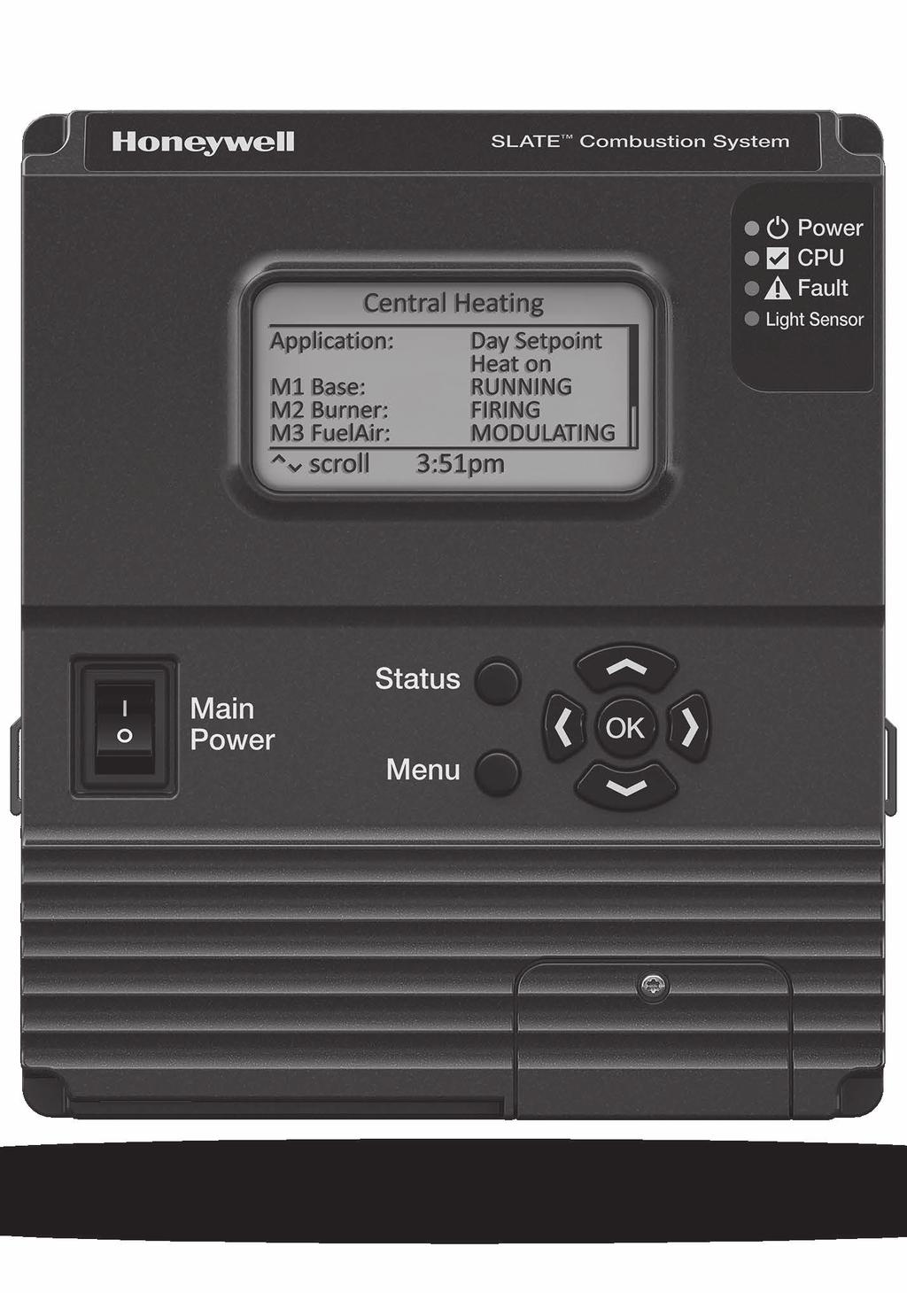
7 Principal Technical Features The R8001A1001 base module provides communications and power supply for the SLATE system, configurable safety for Burner Control, Flame Amps, Fuel Air Ratio, and Limit modules, and programmable logic for Digital and Analog I/O, and Annunciation. Communications The base module provides communications via Modbus IP RS485, BACNet IP/MSTP (RS-485), and Web Services. User Interface The menu-driven user interface provides system status and alerts via a dot matrix display on the front of the module. It is controlled by a 7-button keypad. LED Array There are three LEDs on the front of the base module that provide quick identification of system status and problems. This status is broadcast to other modules on the platform bus in case they are affected by the inoperable module(s). LED Color Description Power No light System does not have power Green System has power CPU Fault Red Green Red No light Table 2. LED Descriptions. No wire sheet or problem with the wire sheet Running Fault Running SLATE BASE MODULE 7 R8001A1001
8 LCD Screen The base module LCD screen will show information about various modules and other parts of the combustion system. Use the arrow keys to navigate the items on the LCD screen, then press OK to select one. In Fig. 2, Burner6 is in Lockout. For additional information, navigate to that menu item and press OK. Slate Application: Running m6 Burner6: Lockout > 1FM-VU-Achk Running m1 Base: Running m2 Burner: Hold > scroll 8:07 am OK:select > > Power CPU Fault Light Sensor Main Power Status Menu OK Fig. 2. LCD display showing a fault (Burner6 is in Lockout). M35422 Additional information, as shown in Fig. 3, is displayed. Use this information to troubleshoot the combustion system
9 < m6 Burner6: FAULT Fault code: 35 Flame is OFF Date: 4 Nov 2014 Time: 3:30 PM scroll <back > > Power CPU Fault Light Sensor Main Power Status Menu OK Fig. 3. Additional lockout information. M35423 Light Sensor SLATE contains a light sensor that is used when the system is exposed to light. This is a power saving feature. Installation WARNING Fire or Explosion Hazard Can cause severe injury, death, or property damage. Verification of safety requirements must be performed each time a control is installed on a burner to prevent possible hazardous burner operation. SLATE BASE MODULE 9 R8001A1001
10 When Installing This Product 1. Read these instructions carefully. Failure to follow them could damage the product or cause a hazardous condition. 2. Check the ratings given in the instructions and on the product to make sure the product is suitable for your application. 3. After installation is complete, check out the product operation as provided in these instructions. Wiring WARNING Electrical Shock Hazard. Can cause severe injury, death, or equipment damage. 1. Disconnect the power supply before beginning installation to prevent electrical shock and equipment damage. More than one power supply disconnect can be involved. Fig. 4. Installing the Base Module on DIN Rail. M
11 2. Wiring must comply with all applicable codes, ordinances and regulations. See Table 1, Table 3, and Recommended Grounding Practices on page 13 for connections and terminals. For DIP switch settings, see DIP Switches on page 15. Note: MS/TP must be wired in a straight line without spurs no star wiring. Main Power Status Menu OK DIP SWITCHES USB ETHERNET REMOVEABLE SD CARD INTERNAL SD CARD INTERNAL CLOCK BATTERY INPUT POWER BACnet AND PROGRAMMABLE POWER SUPPLY L1 L2(N) ALARM A B G M35391 Fig. 5. Base Module inputs and terminals. SLATE BASE MODULE 11 R8001A1001
12 3. Wiring must comply with NEC Class 1 (Line Voltage) wiring. 4. The R8001A1001 should not interfere with the proper safety operation of the controls, limits, and interlocks it is monitoring. After installation, check each control, limit, and interlock to ensure that it is operating properly. DO NOT PLACE JUMPER WIRES ACROSS THE INSTALLATION CONTROLS, LIMITS, AND INTERLOCKS. Application Line voltage terminals Communication lines a Other terminals Recommended Wire Size 14, 16, or 18 AWG copper conductor, 600 volt insulation, moistureresistant wire. 22 AWG two-wire twisted pair with ground, or five-wire. 18 AWG wire insulated for voltages and temperatures for given application. Recommended Part Numbers TTW60C, THW75C, THHN90C Belden 8723 shielded cable or equivalent. TTW60C, THW75C, THHN90C a BACnet MS/TP connections must be wired in daisy chain configuration, 1(a)-1(a), 2(b)-2(b), 3(c)-3(c). The order of interconnection of all the devices is not important. Be aware that the termination DIP switch (number 3) must be used if the SLATE system is at the end of connections over 100 feet. Table 3. Recommended Wire Sizes and Part Numbers
13 Recommended Grounding Practices Use an Earth ground or a signal ground as described below. Earth ground (Base, Rectification Flame Amp Module, other modules optional) 1. Use to provide a connection between the base and the control panel of the equipment. Earth ground must be capable of conducting enough current to blow the breaker in the event of an internal short circuit. 2. Use wide straps or brackets to provide minimum length, maximum surface area ground conductors. If a leadwire is required, use 14 AWG copper wire. 3. Make sure that mechanically tightened joints along the ground path are free of nonconductive coatings and protected against corrosion on mating surfaces. Signal ground Note the 18V system ground is not electrically connected to earth ground. Follow local codes and appliance recommendations to determine if this should be connected to earth ground. Recommended wire routing of leadwires Do not run high voltage ignition transformer wires in the same conduit with the flame detector or data lines. Do not route flame detector or data lines in conduit with line voltage circuits. Enclose flame detector leadwires without armor cable in metal cable or conduit. Follow directions in flame detector instructions. Be sure loads do not exceed the terminal ratings. Refer to the labels or terminal ratings in Table 1. The SLATE system must be mounted in an electrical enclosure. When mounting in an electrical enclosure, provide adequate clearance for servicing, installation and removal of SLATE modules. SLATE BASE MODULE 13 R8001A1001
14 IMPORTANT 1. This equipment generates, uses and can radiate radio frequency energy and, if not installed and used in accordance with these instructions, may cause interference for radio communications. It has been tested and found to comply with the limits of a Class A computing device of part 15 of FCC rules, which are designed to provide reasonable protection against such interference when operated in a commercial environment. Operation of this equipment in a residential area may cause interference; in which case, the user, at their own expense, may be required to take whatever measures are required to correct this interference. 2. This digital apparatus does not exceed the Class A limits for radio noise, set out in the Radio Interference Regulations of the Canadian Department of Communications. 3. For straight gas burner applications, the oil limit and interlock inputs DO NOT need to be jumpered. 4. For straight oil burner applications, the gas limit and interlock inputs DO NOT need to be jumpered. 5. For combination gas-oil burner applications, a double pole, double throw (dpdt) fuel select switch is required. 6. Cable shield must be terminated to ground at both ends. If shielded cable is NOT used, use three-wire twisted cable. WARNING Electrical Shock Hazard. Can cause severe injury, death or equipment damage. Disconnect the power supply from the main disconnect before beginning installation to prevent electrical shock and equipment damage. More than one disconnect can be required
15 DIP Switches The SLATE Base Module has three DIP switches. DIP switches 1 and 2 should be On only if no other MS/TP device providing bias resistors is connected. DIP switch 3 should be On only if SLATE is the last device in the communication chain. SLATE BASE MODULE 15 R8001A1001
16 For more information and detailed instructions on the SLATE display please refer to the SLATE User Guide document located on our website at Automation and Control Solutions Honeywell International Inc. U.S. Registered Trademark Douglas Drive North 2014 Honeywell International Inc. Golden Valley, MN M.S customer.honeywell.com Printed in U.S.A.
SLATE. Sub-Base Module INSTALLATION INSTRUCTIONS R8001S9001
 SLATE Sub-Base Module R8001S9001 INSTALLATION INSTRUCTIONS Scan for more information Application SLATE brings configurable safety and programmable logic together into one single platform. The platform
SLATE. Burner Control Module INSTALLATION INSTRUCTIONS R8001B2001
 SLATE Burner Control Module R8001B2001 INSTALLATION INSTRUCTIONS Scan for more information Application SLATE brings configurable safety and programmable logic together into one single platform. The platform
SLATE. Rectification Ampli-Check Flame Amplifier INSTALLATION INSTRUCTIONS R8001V1031
 SLATE Rectification Ampli-Check Flame Amplifier R8001V1031 INSTALLATION INSTRUCTIONS Scan for more information Application SLATE brings configurable safety and programmable logic together into one single
SLATE. UV Ampli-Check Flame Amplifier INSTALLATION INSTRUCTIONS R8001S1071
 SLATE UV Ampli-Check Flame Amplifier R8001S1071 INSTALLATION INSTRUCTIONS Scan for more information Application SLATE brings configurable safety and programmable logic together into one single platform.
INSTALLATION INSTRUCTIONS
 SLATE 10 Color Touch Screen Display R8001K1010 INSTALLATION INSTRUCTIONS Scan for more information Application SLATE brings configurable safety and programmable logic together into one single platform.
YP7999A1000 ControLinks Fuel Air Ratio Control Panel
 YP7999A1000 ControLinks Fuel Air Ratio Control Panel FEATURES INSTALLATION INSTRUCTIONS Pre-wired and ready to install Includes the R7999A control, wiring subbase and S7999D1048 touchscreen display Commission,
7800 SERIES 22-Terminal Universal Subbase
 7800 SERIES 22-Terminal Universal Subbase FEATURES PRODUCT DATA Q7800B003/2003/U Metal Wall-mount subbase Q7800A005/2005/U Plastic Wall-mount subbase Quick-mount wiring subbase for all 7800 SERIES Relay
Honeywell SLATE ICM Platform
 Honeywell SLATE ICM Platform SUBMITTAL SPECIFICATION Note to specifiers: To specify Honeywell SLATE Integrated Combustion Management System with specified packaged boiler manufactures, Copy and Paste both
7800 SERIES RM7888A Relay Module
 7800 SERIES RM7888A Relay Module SPECIFICATION DATA FEATURES APPLICATION The Honeywell RM7888A Relay Module is a microprocessor-based integrated burner control for industrial process semi-automatically
RM7838A 7800 SERIES Relay Modules
 RM788A 7800 SERIES Relay Modules APPLICATION The Honeywell RM788A is a microprocessor-based integrated burner control for semi-automatically fired gas, oil, or combination fuel single burner applications.
7800 SERIES EC7823/RM7823 Relay Module
 7800 SERIES EC7823/RM7823 Relay Module FEATURES SPECIFICATION DATA APPLICATION The Honeywell EC7823/RM7823 is a microprocessor based Flame Detector Relay that can be fitted with any 7800 SERIES amplifier
7800 SERIES RM7888A Relay Module
 7800 SERIES RM7888A Relay Module FEATURES SPECIFICATION DATA APPLICATION The Honeywell RM7888A Relay Module is a microprocessor-based integrated burner control for industrial process semi-automatically
RM7895A,B,C,D/EC7895A,C; RM7896A,B,C,D 7800 SERIES Relay Modules
 RM79A,B,C,D/EC79A,C; RM796A,B,C,D 700 SERIES Relay Modules INSTALLATION INSTRUCTIONS APPLICATION The RM79A,B,C,D/EC79A,C; RM796A,B,C,D are microprocessor-based integrated burner controls for automatically
7800 SERIES S7830 Expanded Annunciator
 7800 SERIES S7830 Expanded Annunciator PRODUCT DATA FEATURES APPLICATION The S7830 Expanded Annunciator is an enhancement module for use with 7800 SERIES Relay Modules. The S7830 is a microprocessor-based
7800 SERIES EC7885A/RM7885A Relay Module
 7800 SERIES EC7885A/RM7885A Relay Module SPECIFICATION DATA 1. Torch-ignited main burner using the S445A Start-Stop Station, or any conventional knee or foot operated start-stop station. 2. Torch-ignited
7800 SERIES EC7890A,B; RM7890A,B,C Relay Module
 7800 SERIES EC7890A,B; RM7890A,B,C Relay Module SPECIFICATION DATA EC7890 APPLICATION RM7890 The Honeywell EC7890A,B/RM7890 is a microprocessor based integrated burner control for automatically fired gas,
7800 SERIES RM7840E,G,L,M; EC7840L Relay Module
 7800 SERIES RM7840E,G,L,M; EC7840L Relay Module SPECIFICATION DATA Valve Proving features including: VPS test time When (Never, Before, After, Split or Both) FEATURES APPLICATION The Honeywell RM7840 is
7800 SERIES S7800A2142 Keyboard Display Module
 7800 SERIES S7800A2142 Keyboard Display Module PRODUCT DATA The S7800A2142 KDM offers the following technical advancements to the 7800 SERIES devices: APPLICATION The S7800A2142 Keyboard Display Module
RM7897A,C 7800 SERIES Relay Modules
 RM7897A,C 7800 SERIES Relay Modules INSTALLATION INSTRUCTIONS APPLICATION The RM7897A,C are microprocessor-based integrated burner controls for automatically fired gas, oil, or combination fuel single
7800 SERIES EC7895A,C; RM7895A,B,C,D and RM7896A,B,C,D Relay Modules
 7800 SERIES EC7895A,C; RM7895A,B,C,D and RM7896A,B,C,D Relay Modules SPECIFICATION DATA FEATURES APPLICATION The Honeywell EC7895/RM7895/RM7896 is a microprocessor based integrated burner control for automatically
configurable safety and programmable logic SLATE Integrated Combustion Equipment Management The revolutionary integration of
 SLATE Integrated Combustion Equipment Management The revolutionary integration of configurable safety and programmable logic in a single, modular platform Complexity. This is today. Individual components
RM7895A,B,C,D/EC7895A,C; RM7896A,C,D 7800 SERIES
 RM7895A,B,C,D/EC7895A,C; RM7896A,C,D 7800 SERIES Relay Modules INSTALLATION INSTRUCTIONS APPLICATION The RM7895A,B,C,D/EC7895A,C; RM7896A,B,C,D are microprocessor-based integrated burner controls for automatically
R7120M 7800 SERIES Relay Modules
 R7120M 7800 SERIES Relay Modules INSTALLATION INSTRUCTIONS APPLICATION The R7120M are microprocessor-based integrated burner controls for automatically fired gas, oil, or combination fuel single burner
7800 SERIES: EC7895A,C; RM7895A,B,C,D; RM7896A,B,C,D RM7897A,C and RM7898A Relay Modules
 7800 SERIES: EC7895A,C; RM7895A,B,C,D; RM7896A,B,C,D RM7897A,C and RM7898A Relay Modules SPECIFICATION DATA The RM7897A1002 offers selectable pilot operation, intermittent on terminal 8 or interrupted
R7824, R7847, R7848, R7849, R7851, R7852, R7861, R7886 Amplifiers for 7800 SERIES and R7140 Relay Modules
 R7824, R7847, R7848, R7849, R7851, R7852, R7861, R7886 Amplifiers for 7800 SERIES and R7140 Relay Modules PRODUCT DATA indicate the presence of flame when used with 7800 SERIES and R7140 Relay Modules.
7800 SERIES RM7840E,G,L,M Relay Module
 7800 SERIES RM7840E,G,L,M Relay Module APPLICATION SPECIFICATION DATA The Honeywell RM7840 is a microprocessor based integrated burner control for automatically fired gas, oil or combination fuel single
RM7890D; RM7895E,F 7800 SERIES Relay Modules
 RM7890D; RM7895E,F 7800 SERIES Relay Modules PRODUCT DATA The RM7890D; RM7895E,F provides automatic burner sequencing, flame supervision, system status indication, system or self-diagnostics and troubleshooting.
Q7800H Integrated Burner Control Subpanel
 Q7800H Integrated Burner Control Subpanel INSTALLATION INSTRUCTIONS FEATURES Unique subpanel design eliminates extensive wiring in the OEM control panel. One subpanel design covers multiple applications.
7800 SERIES S7800A1167 Keyboard Display Module
 7800 SERIES S7800A1167 Keyboard Display Module PRODUCT DATA The S7800A1167 KDM offers the following technical advancements to the 7800 SERIES devices: Compatible with installed Honeywell 7800 SERIES systems.
CR Series Command Relays
 CR Series Command Relays FEATURES INSTALLATION INSTRUCTIONS Patented 35mm Din-rail mounting flange (US Patent 7,416,421) SPDT Form 1C Relay contacts Pilot duty rated LED status indication Stackable for
Cleaver-Brooks CB780/CB784 Operation and Maintenance Manual
 $25.00 Cleaver-Brooks CB780/CB784 Operation and Maintenance Manual 750-166 DIVISION OF AQUA-CHEM, INC. TO: Owners, Operators and/or Maintenance Personnel This manual presents information that will help
R7824, R7847, R7848, R7849, R7851, R7852, R7861, R7886 Amplifiers for 7800 SERIES and R7140 Relay Modules
 R7824, R7847, R7848, R7849, R7851, R7852, R7861, R7886 Amplifiers for 7800 SERIES and R7140 Relay Modules PRODUCT DATA indicate the presence of flame when used with 7800 SERIES and R7140 Relay Modules.
RM7890A1056, RM7890B SERIES
 RM7890A1056, RM7890B1048 7800 SERIES Relay Modules INSTALLATION INSTRUCTIONS APPLICATION The Honeywell RM7890A1056 and RM7890B1048 Relay Modules are microprocessor based integrated burner controls for
RM7890; RM Vac 7800 SERIES Relay Modules
 RM7890; RM7895 00 Vac 7800 SERIES Relay Modules PRODUCT DATA The RM7890; RM7895 provides on/off automatic burner sequencing, flame supervision, system status indication, system or self-diagnostics and
YP7899C SERIES Burner Management Panel
 YP7C1000 700 SERIES Burner Management Panel INSTALLATION INSTRUCTIONS 65-00, ST700A,C 700 SERIES Plug-In Purge Timer 65-0, S710M Modbus Module 60-06, C707, C7035, C70, C77 Minipeeper UV Flame Detector
MBCE-110/230FR Flame Sensor Module
 MBCE-1001 APRIL 13, 2012 MBCE-110/230FR Flame Sensor Module DESCRIPTION The MBCE-110/230FR modules provide visual indication and electrical outputs that signal the user regarding flame presence in a combustion
Model 17A00 Expansion Enclosure
 HOME AUTOMATION, INC. Model 17A00 Expansion Enclosure Installation Manual Document Number 17I00-1 Rev A March, 2002 Home Automation, Inc. Model 17A00 Expansion Enclosure Installation Manual Document Number
VA301C CONTROLLER WITH BACnet OPTION
 ORDERING INFORMATION VA301C Controller VA301C-DLC VA301C-DLC-BIP Gas detection controller with data logging, display and plastic housing. Gas detection controller with data logging and display, BACnet/IP
7800 Series RM7888A Relay Module
 7800 Series RM7888A Relay Module FEATURES PRODUCT DATA APPLICATION The Honeywell RM7888A Relay Module is a microprocessor based, integrated burner control for industrial process semiautomatically fired
Commercial/Industrial Combustion Control Level Three Announcement
 Commercial/Industrial Combustion Control Level Three Announcement SUBJECT: C6097 requiring venting Model Numbers Affected: C6097A and B Ref. Number L3-08-006 Issue Date 12/9/08 Author P.Yuen/L.Ziller Date
Solid Core and Split Core 0-5, 0-10 Vdc Output Current Sensors CTS-05,10; CTP-05,-10
 Solid Core and Split Core 0-5, 0-10 Vdc Output Current Sensors CTS-05,10; CTP-05,-10 DESCRIPTION FEATURES PRODUCT DATA Solid and Split Core Vdc Output Current Transmitters. Fast Response Time. Integral
Suggested Specification: Benchmark 1.5 Low NOx Gas-Fired Hydronic Boiler(s)
") Furnish and install as shown on AERCO International plans and operation and maintenance manuals, with all applicable codes and authorities having local, state and federal jurisdiction, Benchmark Series
Furnish and install as shown on AERCO International plans and operation and maintenance manuals, with all applicable codes and authorities having local, state and federal jurisdiction, Benchmark Series
Carbon Monoxide Transmitter
 Introduction The CO Transmitter uses an electrochemical sensor to monitor the carbon monoxide level and outputs a field-selectable 4-20 ma or voltage signal. The voltage signal may also be set to 0-5 or
Sola Hydronic Control. An Eco-Friendly Solution.
 Sola Hydronic Control An Eco-Friendly Solution. Honeywell s Sola Boiler Control saves you money and reduces your carbon footprint! Efficient Boiler Control Honeywell s Sola Boiler Control offers energy
MBCE-110/230FR Flame Sensor Module
 MBCE-1001 FEBRAURY 6, 2017 MBCE-110/230FR Flame Sensor Module exida FMEDA SIL2 SEE NOTE 1 ON PAGE 4 DESCRIPTION The MBCE-110/230FR modules provide visual indication and electrical outputs that signal the
R7910A SOLA (Hydronic Control) and R7911 SOLA (Steam Control) Systems
 and R7911 SOLA (Steam Control) Systems") R7910A SOLA (Hydronic Control) and R7911 SOLA (Steam Control) Systems APPLICATION The R7910 SOLA hydronic boiler and the R7911 SOLA steam control systems provide heat control, flame supervision, circulation
R7910A SOLA (Hydronic Control) and R7911 SOLA (Steam Control) Systems APPLICATION The R7910 SOLA hydronic boiler and the R7911 SOLA steam control systems provide heat control, flame supervision, circulation
Refer to Bulletin E-1101 for detailed information on the FLAME-MONITOR System.
 The Fireye EP260, EP270 (early spark termination), or EP265 (pilot stabilization) programmer modules are used with the FLAME-MONITOR Burner Management Control System (P/N E110). Several operational characteristics
UltraLITE Model ELU Centralized Emergency Lighting Inverter 4.2 KW- 5 KW
 12/23/16 Rev 9 UltraLITE Model ELU General Specification 4.2 KW to 5 KW UltraLITE Model ELU Centralized Emergency Lighting Inverter 4.2 KW- 5 KW 1.0 General General Specification This specification describes
Solid Core and Split Core 4-20 ma Output Current Sensors CTS-20; CTP-20
 Solid Core and Split Core 4-20 ma Output Current Sensors CTS-20; CTP-20 PRODUCT DATA FEATURES Solid or split core loop-powered current transmitters Fast response time Integral DIN rail mounting flange
7800 SERIES EC7810A, EC7820A Relay Module
 7800 SERIES EC780A, EC780A Relay Module PRODUCT DATA GENERAL The Honeywell EC780A or EC780A Relay Module is a microprocessor based integrated burner control for automatically fired gas, oil, or combination
R7910A SOLA (Hydronic Control) and R7911 SOLA (Steam Control) Systems
 and R7911 SOLA (Steam Control) Systems") R7910A SOLA (Hydronic Control) and R7911 SOLA (Steam Control) Systems INSTALLATION INSTRUCTIONS APPLICATION The R7910 SOLA hydronic boiler and the R7911 SOLA steam control systems provide heat control,
R7910A SOLA (Hydronic Control) and R7911 SOLA (Steam Control) Systems INSTALLATION INSTRUCTIONS APPLICATION The R7910 SOLA hydronic boiler and the R7911 SOLA steam control systems provide heat control,
APPLICATION SPECIFICATIONS INSTALLATION INSTRUCTIONS. The following assumptions apply when using the RM7840G,L, RM7800L, EC7840L:
 INSTALLATION INSTRUCTIONS APPLICATION The Honeywell RM7800L/40G,L and EC7840L Relay Modules are microprocessor-based integrated burner controls for automatically fired gas, oil, or combination fuel single
MBCE-110/230UV Flame Sensor Module
 MBCE-1002 FEBRUARY 3, 2017 MBCE-110/230UV Flame Sensor Module DESCRIPTION The MBCE-110/230UV modules provide visual indication and electrical outputs that signal the user regarding flame presence in a
SCC Inc. TS Series. Technical Instructions. Document No. TS 1000 June 25, TS Touchscreen Kits. Description. Touchscreen
 TS Touchscreen Kits for use with LMV3, LMV5 and RWF Controls June 25, 2018 Touchscreen Description Plate Kit Enclosure TS series touchscreen kits provide a human machine interface (HMI) with a Siemens
T M. User Manual. MarinaGuard. Ground Fault Monitoring Panel For Marina Shore Power
 T M User Manual MarinaGuard Ground Fault Monitoring Panel For Marina Shore Power NAE1095810 / 03.2013 T M Bender Inc. USA: 700 Fox Chase Coatesville, PA 19320 Toll-Free: 800-356-4266 Phone: 610-383-9200
A New Standard of Excellence
 A New Standard of Excellence PREVENTION IS SO EASY... LIVING THROUGH A DISASTER IS NOT The reliable identification of low combustion oxygen in a fired heater or boiler has always been critical to the effectiveness
LORAIN CIP 4890/48120 DC Power System
 DC Power for Business-Critical Continuity Key Features Compact flexibility provides rectifiers, distribution, and controller in one shelf Constant power delivers more current at lower voltages to meet
Power Supply Display Module PSDM. Installation and Operation Manual
 Power Supply Display Module PSDM Installation and Operation Manual Read this manual before using this product. Failure to follow the instructions and safety precautions in this manual can result in serious
Networked Access Control Panel. Installation Guide
 XP2M Networked Access Control Panel V1.0X Installation Guide X P 2 M A C C E S S C O N T R O L S Y S T E M Installation Guide Document Ref: PLAN XP2M Installation Guide V4(G)2010 Access Control Services
SP-1000X. Panic Device Power Controller Installation Guide. Rev
 TM SP-1000X Panic Device Power Controller Installation Guide Rev. 120213 Overview: SP-1000X will operate up to two (2) 24VDC panic hardware devices simultaneously. It is designed to handle the high current
ACS-30 MULTIPOINT COMMERCIAL HEAT-TRACING SYSTEM PRODUCT OVERVIEW. ACS-30 System
 SHIFT TEST BACK ENTER C910 SERIES STATUS OUTPUT ACS-30 MULTIPOINT COMMERCIAL HEAT-TRACING SYSTEM ACS-30 System MONITOR CONFIG POWER CONTROL MODULE ACCS-PCM-5 PROGRAMMABLE SINGLE POINT HEAT-TRACING CONTROLLER
R7824, R7847, R7848, R7849, R7851, R7852, R7861, R7886 Amplifiers for 7800 SERIES and R7140 Relay Modules
 R784, R7847, R7848, R7849, R7851, R785, R7861, R7886 Amplifiers for 7800 SERIES and R7140 Relay Modules PRODUCT DATA and R7140 Relay Modules. This is not European Community (CE) approved for EC7810, EC780,
isopv and AGH-PV Ground Fault Detector for Ungrounded Solar Arrays up to 1100 V And Isolation Tester Prior to Array Startup (Grounded and Ungrounded)
") T M 1 isopv and AGH-PV Ground Fault Detector for Ungrounded Solar Arrays up to 1100 V And Isolation Tester Prior to Array Startup (Grounded and Ungrounded) Technical Bulletin NAE1012372 / 03.2015 isopv
T M 1 isopv and AGH-PV Ground Fault Detector for Ungrounded Solar Arrays up to 1100 V And Isolation Tester Prior to Array Startup (Grounded and Ungrounded) Technical Bulletin NAE1012372 / 03.2015 isopv
IS Series Pressure Sensing Switches
 IS Series Pressure Sensing Switches FEATURES INSTALLATION INSTRUCTIONS IS3 PRESSURE SWITCH APPLICATION IS2 PRESSURE SWITCH The IS Series of pressure sensing switches offers the same proven compression
RPSMLR2 RPSMLR2BB. Panic Device Power Controller Installation Guide LISTED. Rev
 RPSMLR2 RPSMLR2BB Panic Device Power Controller Installation Guide LISTED Rev. 102715 Overview: RPSMLR2BB, RPSMLR2 will operate up to two (2) 24VDC panic hardware devices simultaneously. It is designed
ELECTRONIC FLAME SUPERVISION MULTI-BURNER
 MULTI-BURNER MODEL: SENS-A-FLAME II Revision: 0 7112 DESCRIPTION Model 7112 Sens-A-Flame II is a second generation solid-state programmable combustion safeguard for supervising multiple burner ovens, furnaces,
SPECIFICATION: AlarmLine TM INTELLIGENT LINEAR HEAT DETECTION
 1. GENERAL SPECIFICATION 1.1 The contractor shall provide an Intelligent AlarmLine Linear Heat Detection System to perform the following functionality: A. Fire Alarm, Supervisory and Trouble-Event Initiation
RMS/RPX Reader. User Manual
 RMS/RPX Reader User Manual Copyright Disclaimer Trademarks and patents Intended use FCC compliance Copyright 2005, GE Security Inc. All rights reserved. This document may not be copied or otherwise reproduced,
Operating & Maintenance Manual. Alert-4 Ethernet LCD Master Alarm
 Operating & Maintenance Manual Alert-4 Ethernet LCD Master Alarm w w w. a m i c o. c o m Contents User Responsibility 4 Introduction 4 Features 5 Description of the Alarm 5 Shipment Details 5 The Alarm
INSTALLATION INSTRUCTIONS
 TT-1343 5/06b INSTALLATION INSTRUCTIONS Original Issue Date: 8/03 Model: Automatic Transfer Switches Equipped with Series 1000 Programmable Controller Market: ATS Subject: Remote Annunciator Kits GM28938-KP1,
FIREYE NXF4000 ADVANCED BURNER MANAGEMENT SYSTEM with INTERNAL FLAME SAFEGUARD
 BURNER MANANGEMENT SYSTEM NXF4000-SPEC AUGUST 5 2017 PRODUCT GUIDE SPECIFICATION FIREYE NXF4000 ADVANCED BURNER MANAGEMENT SYSTEM with INTERNAL FLAME SAFEGUARD GENERAL OVERVIEW 1.1.1. Each burner shall
KT-100 Door Controller
 WARNING: This manual contains information on limitations regarding product use and function and information on the limitations as to liability of the manufacturer. The entire manual should be carefully
Models NFPA 1221-A, NFPA 1221-B Public Safety DAS Annunciator Panel. Revision E 61117
 Models NFPA 1221-A, NFPA 1221-B Public Safety DAS Annunciator Panel Revision E 61117 CAUTION: (Read This First) This panel has been designed to make it nearly bullet proof to mistakes made when wiring
NGC-40 PANEL MOUNTED ADVANCED MODULAR HEAT-TRACING CONTROL SYSTEM HTC HTC3 PRODUCT OVERVIEW
 NGC-40 PANEL MOUNTED ADVANCED MODULAR HEAT-TRACING CONTROL SYSTEM Local configuration and monitoring with Raychem Touch 1500 touch screen display PRODUCT OVERVIEW The nvent RAYCHEM NGC-40 is a multipoint
EC-BOS-602/616 AX Security
 D a t a s h e e t EC-BOS-602/616 AX Security Comprehensive, easy-to-use Access Control management solution Overview The heart of EC-Net AX Security is the EC- BOS-602/616 AX Security, an advanced IP-based
ISOMETER IRDH375. Insulation monitoring device for unearthed AC, AC/DC and DC systems (IT systems)
") Insulation monitoring device for unearthed AC, AC/DC and DC systems (IT systems) IRDH375_D00124_01_D_XXEN/07.2018 Insulation monitoring device for unearthed AC, AC/DC and DC systems (IT systems) Product
Insulation monitoring device for unearthed AC, AC/DC and DC systems (IT systems) IRDH375_D00124_01_D_XXEN/07.2018 Insulation monitoring device for unearthed AC, AC/DC and DC systems (IT systems) Product
21-light Remote Annunciator. Owner s Manual
 21-light Remote Annunciator Owner s Manual Annunciator Description... Inside Font Cover Detailed Specifications... 1 Environmental Specifications... 1 Power Supply Requirements... 1 Communication With
C SINGLE-POINT HEAT-TRACING CONTROL SYSTEM PRODUCT OVERVIEW
 SINGLE-POINT HEAT-TRACING CONTROL SYSTEM PRODUCT OVERVIEW SHIFT TEST SHIFT C910 SERIES ALARM MONITOR CONFIG BACK ENTER PROGRAMMABLE SINGLE POINT HEAT-TRACING CONTROLLER HEAT-TRACING CONTROLLER STATUS ALARM
C554A Cadmium Sulfide Flame Detector
 C554A Cadmium Sulfide Flame Detector FEATURES PRODUCT DATA Cadmium sulfide sensing element provides faster response than bimetal sensors. On flame failure, the cad cell causes the oil primary control to
NGC-40 PANEL MOUNTED ADVANCED MODULAR HEAT-TRACING CONTROL SYSTEM HTC HTC3
 NGC-40 PANEL MOUNTED ADVANCED MODULAR HEAT-TRACING CONTROL SYSTEM Local configuration and monitoring with Raychem Touch 1500 touch screen display PRODUCT OVERVIEW The Raychem NGC-40 is a multipoint electronic
WARRANT Y AND LIMITS OF LIABILIT Y Vulcain Inc. warrants to the original purchaser that its product, and the component parts thereof, will be free fro
 A d e v i h c r D c o n e m u WARRANT Y AND LIMITS OF LIABILIT Y Vulcain Inc. warrants to the original purchaser that its product, and the component parts thereof, will be free from defects in workmanship
Dual Input ph/orp Analyzer
 Instruction Sheet PN 51A-1055pH/rev.I February 2006 Model 1055 SOLU COMP II Dual Input ph/orp Analyzer Model Option 1055-22-32 For additional information, please refer to the Instruction Manuals CD shipped
Across-the-Line SERIES MP300 Combined Manual and Automatic
 Across-the-Line SERIES MP300 Combined Manual and Automatic Metron Fire Pump Controllers conform to the latest requirements of National Fire Protection Association s Standard for Centrifugal Fire Pumps
4100U City and Relay Cards Installation Instructions
 4100U City and Relay Cards Installation Instructions Introduction This publication describes the installation procedure for the following: 4100-6031/6032 City Circuit Cards 4100-6033 Alarm Relay Card Inspecting
LC3000 Level Controller Installation and Maintenance Instructions
 4025550/12 IM-P402-36 AB Issue 12 LC3000 Level Controller Installation and Maintenance Instructions 1. General safety information LC3000 NORM ALARM TEST 2. General product information 3. Installation 4.
THERMAL BUILDING SOLUTIONS EN-TraceTekTTSIM1A-IM-H /16
 TraceTek TTSIM-1A TraceTek Sensor Interface Module with Relay Installation/OPERATION Instructions Approvals and Certifications TYPE NM General Signaling Equipment 76LJ Only AC versions are UL listed and
Booster Power Supply Manual
 Supply Manual DEVELOPED BY COPYRIGHT NOTICE General Signal Building Systems Corporation 6411 Parkland Drive Sarasota, FL 34243 (941) 739-4300 Copyright 1999 General Signal Building Systems Corporation
TTSIM-2 TRACETEK SENSOR INTERFACE MODULE WITH LCD AND RELAY INSTALLATION/OPERATION INSTRUCTIONS
 TTSIM-2 TRACETEK SENSOR INTERFACE MODULE WITH LCD AND RELAY INSTALLATION/OPERATION INSTRUCTIONS GENERAL INFORMATION Please read these instructions and keep them in a safe place. These instructions must
T7079A,B Solid State Remote Temperature Controllers
 T7079A,B Solid State Remote Temperature Controllers FEATURES PRODUCT DATA Switch selection of heat or cool mode. Temperature sensing up to 400 feet. Does not require field calibration. 0K NTC temperature
Rev Pulse Modulating Anti- Sweat Control (PMAC II) Installation and Operation Manual
 Installation and Operation Manual") 026-1501 Rev 5 3-20-03 Pulse Modulating Anti- Sweat Control (PMAC II) Installation and Operation Manual 1640 Airport Road, Suite 104 Kennesaw, GA 31044 Phone: (770) 425-2724 Fax: (770) 425-9319 ALL RIGHTS
026-1501 Rev 5 3-20-03 Pulse Modulating Anti- Sweat Control (PMAC II) Installation and Operation Manual 1640 Airport Road, Suite 104 Kennesaw, GA 31044 Phone: (770) 425-2724 Fax: (770) 425-9319 ALL RIGHTS
Two-Channel Gas Controller
 Two-Channel Gas Controller Specifications subject to change without notice. USA 09 Page of DESCRIPTION Highly configurable, UL 0 performance-tested and -certified, and wall-mounted gas monitor; continuously
LORAIN CSP DC Power System
 DC Power for Business-Critical Continuity Key Features Compact flexibility provides more space for revenue generating equipment Constant power delivers more current at lower voltages to meet load or recharge
NGC-40 Advanced Heat-Tracing Control System
 NGC-40 Advanced Heat-Tracing Control System Local configuration and monitoring with Raychem Touch 1500 touch screen display Heat-tracing system NGC-40 system Remote configuration and monitoring with Raychem
SmartVFD HVAC and BYPASS
 SmartVFD HVAC and BYPASS The Smart Choice For Energy Savings Energy Savings Are Smart For You. And Smart For The World. About three-quarters of the energy consumed by commercial buildings is in the form
Halton SAFE / 7.14 user guide and installation instructions
 Halton SAFE / 7.14 user guide and installation instructions VERIFIED SOLUTIONS BY H A LTO N Enabling Wellbeing Table of contents 1 System description 3 2 User Accounts 4 3 Main menu 7 3.1 Main menu - Change
LG ELECTRONICS Air Conditioning Technologies LG Guide Specifications Controls
 LG ELECTRONICS Air Conditioning Technologies LG Guide Specifications Controls 1 Article I. General Section 1.01 Section 1.02 Section 1.03 System Description Quality Assurance Storage and Handling Article
C7232A,B Sensor and Controller CARBON DIOXIDE SENSOR
 C7232A,B Sensor and Controller CARBON DIOXIDE SENSOR PRODUCT DATA C7232A C7232B FEATURES Used for CO 2 based ventilation control. Models available with LCD that provides sensor readings and status information.
7800 SERIES RM7824A Relay Module
 7800 SERIES RM7824A Relay Module FEATURES PRODUCT DATA APPLICATION The Honeywell RM7824A Relay Module is a 24 Vdc microprocessor-based integrated burner control for automatically fired gas, oil or combination
Installation Guide for models:
 140 58th St. Brooklyn, NY Access Power Controllers with Power Supplies Installation Guide for models: Maximal3FD - 12VDC @ 4.6 amp or 24VDC @ 5.2 amp. - Sixteen (16) PTC protected power-limited outputs.
TTSIM-1A. TraceTek Sensor Interface Module with Relay. Installation/Operation Instructions. Installation Items (not supplied) Tools Required.
 Tools Required.") TTSIM-1A TraceTek Sensor Interface Module with Relay Installation Items (not supplied) General Information Installation/Operation Instructions Please read these instructions and keep them in a safe place.
TTSIM-1A TraceTek Sensor Interface Module with Relay Installation Items (not supplied) General Information Installation/Operation Instructions Please read these instructions and keep them in a safe place.