LZR -I30. max. detection range of 30 ft x 30 ft LASER SCANNERS FOR INDUSTRIAL DOORS LZR-I Page 1 of 12
|
|
|
- Tracy Preston
- 5 years ago
- Views:
Transcription


1 EN LZR -I30 LASER SCANNERS FOR INDUSTRIAL DOORS max. detection range of 30 ft x 30 ft LZR-I Page of


 The visible")


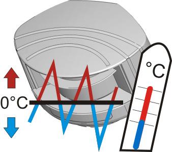

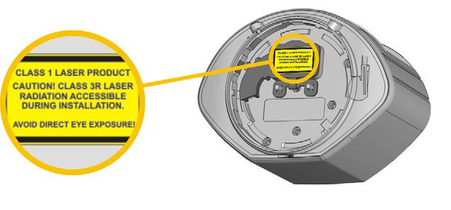
2 SAFETY The device contains IR and visible laser diodes. IR laser: wavelength 905nm; max. output pulse power 75W (Class according to IEC 6085-) Visible laser: wavelength 650nm; max. output CW power 3mW (Class 3R according to IEC 6085-) The visible laser beams are inactive during normal operation. The installer can activate the visible lasers if needed. CAUTION! Use of controls, adjustments or performance of procedures other than those specified herein may result in hazardous radiation exposure. Do not look into the laser emitter or the visible red laser beams. The warranty is void if unauthorized repairs are made or attempted by unauthorized personnel. Only trained and qualified personnel may install and adjust the sensor. Test the proper operation of the installation before leaving the premises. The manufacturer of the door system is responsible for carrying out a risk assessment and installing the sensor and the door system in compliance with applicable national and international regulations and standards on door safety and if applicable, the machinery directive 006/4/EC. Other use of the device is outside the permitted purpose and can not be guaranteed by the manufacturer. The manufacturer cannot be held responsible for incorrect installations or inappropriate adjustments of the sensor. INSTALLATION AND MAINTENANCE Avoid extreme vibrations. Do not cover the front screens. Avoid moving objects and light sources in the detection field. Avoid the presence of smoke and fog in the detection field. Avoid condensation. Avoid exposure to sudden and extreme temperature changes. Avoid direct exposure to high pressure cleaning. Do not use aggressive products to clean the front screens. Wipe the front screens regularly with a clean and damp cloth. Keep the sensor permanently powered in environments where the temperature can descend below 4 F. Page of LZR-I
 9. adjustable bracket 0. cable conduits (4) LED-SIGNAL 3 4. Detection LED: relay - optional field. Detection LED: relay - safety field 3. Error LED 4.")

3 DESCRIPTION laser sweep emission. laser sweep reception 3. LED-signals (4) 4. screws for position lock () 5. connector 6. protection cover 7. visible laser beams (3) 8. notches for tilt angle adjustment () 9. adjustable bracket 0. cable conduits (4) LED-SIGNAL 3 4. Detection LED: relay - optional field. Detection LED: relay - safety field 3. Error LED 4. Power LED LED flashes quickly LED flashes DETECTION LEDs ERROR LED POWER LED LED flashes slowly detection no detection error no error power no power LED flashes once x LED is off All 4 LEDs can be switched off and on again by remote control. This can be useful in cases where the sensor should not draw any attention. SYMBOLS Caution! Laser radiation Remote control sequence Possible remote control adjustments Factory values According to Not according to EN ISO 3849-:008 CAT, Pl «d» Attention! Important! Tip Info LZR-I Page 3 of


4 HOW TO USE THE REMOTE CONTROL 30 minutes after last use, the sensor locks the access to the remote control session. Cut and restore power supply. The remote control session is accessible again during 30 minutes. 30 After unlocking, the red LED flashes and the sensor can be adjusted by remote control. If the red LED flashes quickly after unlocking, you need to enter an access code from to 4 digits. To end an adjustment session, always lock the sensor. ADJUSTING ONE OR MORE PARAMETERS CHECKING A VALUE x X = number of flashes = value of the parameter 4x x = field width: 4. m x = field width is defined by teach-in 3x RESTORING TO FACTORY VALUES teach-in SAVING AN ACCESS CODE The access code is recommended for sensors installed close to each other. DELETING AN ACCESS CODE Enter the existing code Page 4 of LZR-I


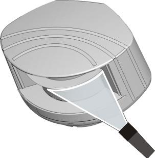
5 MOUNTING 4 in 3 in in 45 Use the mounting template to position the sensor correctly. The grey area indicates the detection range. Drill 4 holes and make a hole for the cable if possible. Pass the cable +/- 4 in though the cable opening. If drilling an opening is not possible, use the cable conduits on the back side of the bracket. 45 Position the bracket and fasten the 4 screws firmly in order to avoid vibrations. 4 5 Open the protection cover, plug the connector and position the cable in the slit. Close the protection cover and fasten it firmly. Position the housing on the bracket and turn the sensor until the two triangles are face to face. Use the LBA accessory if needed. WIRING RED BLACK + - POWER SUPPLY Use a Power Supply Module (4V DC, 0.75 A) if needed. WHITE GREEN WHITE/BLACK GREEN/WHITE BLUE BLUE/WHITE ORANGE ORANGE/BLACK + - RELAY - OPTIONAL FIELD RELAY - SAFETY FIELD TEST NOT USED The sensor tests both relays. Door control without test: connect red and blue wires to power supply (no polarity) LZR-I Page 5 of


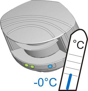
6 3 POSITIONING Unlock the sensor and activate the visible laser beams in order to position the curtains parallell to the door. The visible laser beams stay activated for 5 minutes or can be turned off by the same sequence. Adjust the lateral position of the detection field. Adjust the tilt angle of the detection field with the hex key. Lock the position of the mounting bracket to avoid malfunctioning in case of extreme vibrations. The distances between the curtains depend on the mounting height and side. 6.5 ft The visible laser beams indicate approximately the postion of curtain C. 94 C The distance between the inner curtains of the sensors must be max. 8 in to ensure safety according to EN ISO 3849-:008 CAT, Pl «d». 0 in 4 MOUNTING SIDE Check and select the corresponding mounting side if necessary. Stay outside of the detection field to avoid disturbances. left right left right centre WITH BACKGROUND The sensor memorizes the floor as reference point and signals a fault when its orientation is changed. WITHOUT BACKGROUND No reference point, no signal. A teach-in is launched, the sensor learns its environment and automatically determines the detection field(s). Both RED LEDs flash slowly and the 3 visible laser beams automatically light up during 30 seconds. Ex: teach-in After setting the mounting side, the safety and the optional field have the same dimensions. Page 6 of LZR-I

7 5 SAFETY FIELD CONFIGURATION (RELAY ) SAFETY FIELD TEACH-IN Launch a teach-in after changing the sensor position or when new objects are added to or changed in the detection zone. During teach-in, the detection field should be free of snow buildups, heavy rain, snowfall, fog or other moving objects. Wait for the sensor to learn its environment or lock it by remote control. 3 s max. 30 s During teach-in, the sensor learns its surroundings and adapts the detection field shape to these. Objects in the detection field will be cut out. FIELD DIMENSIONS After the teach-in, the field dimensions can be reduced by remote control. WIDTH HEIGHT no field MIN - - MAX in 360 in 00 in in 360 in 00 in Ex: for a field width of 6 in The field is by default limited to 00 in x 00 in. You can adapt the dimensions by remote control, but they can never be bigger than the shape which was defined by the teach-in. FACTORY VALUES LZR-I Page 7 of
 Install or virtual push buttons as activation zone(s) to open the door «manually».")


8 6 OPTIONAL FIELD CONFIGURATION (RELAY ) Make sure the white and yellow wires are connected to the corresponding inputs before configuring the optional field. VIRTUAL PUSH BUTTON TEACH-IN (VPB) Install or virtual push buttons as activation zone(s) to open the door «manually». Apply the vitual push button sticker(s) within the optional field. Launch a VPB teach-in to configure the detection zone(s). When the red LED flashes very slowly after 3 seconds, hold your hand in front of the sticker to learn the detection zone. The green LED flashes 3x to confirm the selection. When the red LED flashes again, learn a second (max. ) detection zone or wait until the LED switches to green. Launch a new VPB teach-in each time the sensor position is changed or new objects are added to or changed in the detection zone. ATTENTION! This VPB teach-in is different from the safety field teach-in. max x 3 s 3 FIELD DIMENSIONS Reduce the field dimensons if needed. In order to configure the field dimensions, you have to cancel the virtual push button function by launching a new VPB teach-in without any movement in the detection field. WIDTH HEIGHT same as safety field no field MIN - - MAX in 360 in 360 in in 360 in 360 in Change output configuration to value 3. Test the good functioning of the installation before leaving the premises. FACTORY VALUES Page 8 of LZR-I

.")
 indoor outdoor low outdoor med outdoor high Choose between environment or object.")
 off 3 4 6 8 in OUTPUT ACTIVATION DELAY (approximate values) off 00 00 300 400 500 600 700 800 900 ms The relays are triggered when the")
9 OTHER REMOTE CONTROL CONFIGURATIONS ACTIVE DETECTION CURTAINS X X X X CURTAIN C C C3 C4 curtain is inactive on both fields Ex: C + C are active on safety field C3 + C4 are active on optional field C C C3 C4 curtain is active on optional field curtain is active on safety field curtain is active on both fields C is active on both fields C+C3 are active on safety field C4 is inactive All curtains are active on both fields The distances between the curtains depend on the mounting height and side. When mounted on the left, the distance between curtain C and curtain C4 is approximately 4 in for every 3.5 ft (mounting height). Example: at 00 in the distance between C and C4 is 0 in. IMMUNITY FILTER FOR CRITICAL ENVIRONMENTS (RAIN, SNOW, FOG) indoor outdoor low outdoor med outdoor high Choose between environment or object. UNCOVERED ZONE in Increase in case of snow, dead leaves, etc. MIN. OBJECT SIZE (approximate values) off in OUTPUT ACTIVATION DELAY (approximate values) off ms The relays are triggered when the detection duration the selected time. DETECTION FIELD REDIRECTION R optional optional or safety R safety safety OUTPUT CONFIGURATION R A - NO P - NC P - NC A - NO A = active P = passive R R R P - NC A - NO P - NC A - NO NO = normally open NC = normally closed FACTORY VALUES R = RELAY OUTPUT LZR-I Page 9 of
10 TROUBLESHOOTING No blue LED There is no power. Check cable and connexion. The polarity of the power supply is inverted. Check the polarity of the power supply. Only the blue LED is on. The detection LED remains green. All LEDs have been deactivated by remote control. The test input is not connected. The detection field is too small or deactivated. The object size is too small. Activate the LEDs by remote control. Check wiring. The RED and BLUE cable have to be connected to the test input or the power supply. Check the size of the fields. Launch a teach-in. Decrease the min. object size. The detection LED remains red. Someone or something is in the detection field. Step out of the field and/or remove the any object(s) from the field. The orange LED is flashing and the detection LEDs are red. The field is touching the floor, the wall or the door, which leads to detection. No background (reference point) is found. 3 3 Activate the 3 red beams and check if the position of the sensor is correct. If not, adjust the hex screws. Verify the field size. Launch a teach-in. Check the position of the sensor. Check the mounting side setting. If there is no background, set the mounting side to value 3 to 5. Launch a new teach-in. The sensor is masked. Verify and clean the front screens with a damp cloth. The orange LED is on. The power supply voltage is exceeding the acceptable limits. Check the power supply voltage. The sensor exceeds its temperature limits. Verify the outside temperature where the sensor is installed. Eventually protect the sensor from sunlight using a cover. Internal error Wait a few seconds. If the LED remains ON, reset the power supply. If the LED turns on again, replace the sensor. The sensor does not respond to the remote control. 30 minutes after last use of the remote control, the sensor locks the access to the remote control session. Cut and restore power supply. The remote control session is accessible again during 30 minutes. The batteries in the remote control are not installed properly or dead. Verify or replace the batteries. The remote control is badly pointed. Point the remote control towards the sensor, but with a slight angle. The RC should not be pointed in a right angle in front of the sensor. A reflective object is in close proximity to the sensor. Avoid highly reflective material in proximity to the sensor. The sensor does not unlock. You have to enter an access code or the wrong code was entered. Cut and restore power supply. No code is required to unlock during the first minute after powering. Page 0 of LZR-I
11 TECHNICAL SPECIFICATIONS Technology: Detection mode: Max. detection range: Uncovered zone: Remission factor: Angular resolution: Min. detected object size (typ.): (in proportion to object distance) Testbody: Emission characteristics: IR laser: Red visible laser: Supply voltage: Power consumption: Peak current at power-on: Cable length: Response time: Output: Max. switching voltage: Max. switching current: Switching time: Output resistance: Voltage drop on output: Leakage current: Input: Max. contact voltage: Voltage threshold: Response time monitoring input: LED-signal: Dimensions: Material: Colour: Mounting angles on bracket: Rotation angles on bracket: Tilt angles on bracket: Protection degree: Temperature range: Humidity: Vibrations: Pollution on front screens: Expected lifetime: Norm conformity: laser scanner, time-of-flight measurement motion and presence (EN 453 Typ. E) 30 ft x 30 ft - 9 in (adjustable) > % 0, in ;.4 97 in ; ft 700 mm x 300 mm x 00 mm (testbody A according to EN 445) wavelength 905 nm; max. output pulse power 75 W (CLASS ) wavelength 650 nm; max. output CW power 3 mw (CLASS 3R) 0-35 V sensor side (to be operated from SELV compatible power supplies only) < 5 W.8 A (max V) 33 ft typ. 0 ms; max. 80 ms (+ output activation delay) electronic relays (galvanic isolated - polarity free) 35 V DC / 4 V AC 80 ma (resistive) t ON =5 ms; t OFF =5 ms typ 30 Ω < ma < 0 µa optocouplers (galvanic isolated - polarity free) 35 V DC (over-voltage protected) Log. H: >8 V DC; Log. L: <3 V DC < 5 ms blue LED: power-on status orange LED: error status bi-coloured LEDs: detection/output status (green: no detection; red: detection) 5.0 in (D) x 3.6 in (W) x.75 in (H) (mounting bracket in) PC/ASA black or white -45, 0, 45-5 to +5 (lockable) -3 to +3 IP65 - F to +40 F if powered; +4 F to +40 C unpowered 0-95 % non-condensing < G max. 30 %; homogenous 0 years 006/95/EC: LVD; 00/95/EC: RoHS; 004/08/EC: EMC; 006/4/EC: MD; EN 453:000 chapter 5...6, chapter 5.5. Safety device E; EN 978:009; EN ISO 3849-:008, Pl d ; EN 6059:00; IEC 6085-:007; EN :005; EN :005; EN :006; IEC 6496-:009; EN :008 ESPE Type ; EN 606:005 SIL Specifications are subject to changes without prior notice. All values measured in specific conditions LZR-I Page of

12 BEA Original instructions PLEASE KEEP FOR FURTHER USE DESIGNED FOR COLOR PRINTING BEA hereby declares that the LZR -I00/-I0 is in conformity with the basic requirements and the other relevant provisions of the directives 006/95/EC, 00/95/EC, 004/08/EC and 006/4/EC. Notified Body for EC inspection: TÜV NORD CERT GmbH, Langemarckstr. 0, 454 D-Essen EC-type examination certificate number: Angleur, May 0 Jean-Pierre Valkenberg, Authorized representative and responsible for technical documentation The complete declaration of conformity is available on our website: For EC countries: according to the directive 0/9/EU for Waste Electrical and Electronic Equipment (WEEE) 4/7 Tech Support: Customer Service: General Tech Questions: Tech_Services@beainc.com Tech Docs: Page of LZR-I
LZR -I100/ -I110. LASER SCANNERS for industrial doors. User s Guide for product version 0600 and more
 EN LZR -I00/ -I0 LASER SCANNERS for industrial doors I00: max. detection range of 9.9 m x 9.9 m I0: max. detection range of 5.0 m x 5.0 m User s Guide for product version 0600 and more SAFETY The device
XGUARD-10/-5. LASER SCANNERS for industrial doors. User s Guide for product version 0600 and more
 EN XGUARD-0/-5 LASER SCANNERS for industrial doors XGUARD-0: max. detection range of 9.9 m x 9.9 m XGUARD-5: max. detection range of 5.0 m x 5.0 m User s Guide for product version 0600 and more SAFETY
LZR -H110. LASER SCANNER FOR BARRIERS & GATES with max. detection range of 5.0 m x 6.5 m (16.5 ft x21 ft) User s Guide
 User s Guide") EN LZR -H110 LASER SCANNER FOR BARRIERS & GATES with max. detection range of 5.0 m x 6.5 m (16.5 ft x21 ft) User s Guide 75.5897.02 LZR-H110 20170821 Page 1 of 12 SAFETY The device contains IR and visible
EN LZR -H110 LASER SCANNER FOR BARRIERS & GATES with max. detection range of 5.0 m x 6.5 m (16.5 ft x21 ft) User s Guide 75.5897.02 LZR-H110 20170821 Page 1 of 12 SAFETY The device contains IR and visible
active infrared 875 nm < 250 mw/m² motion & presence 157 in x 157 in (emitting spots**) 2 in/s to activate detection 250 ms 15-45
 2 in/s to activate detection 250 ms 15-45") Please keep for further use Designed for color printing Other use of the device is outside the permitted purpose and can not be guaranteed by the manufacturer. The manufacturer cannot be held responsible
Please keep for further use Designed for color printing Other use of the device is outside the permitted purpose and can not be guaranteed by the manufacturer. The manufacturer cannot be held responsible
LZR -WIDESCAN OPENING, PRESENCE & SAFETY SENSOR FOR INDUSTRIAL DOORS
 LZR -WIDESCAN EN OPENING, PRESENCE & SAFETY SENSOR FOR INDUSTRIAL DOORS User s Guide for product version 0300 and higher See product label for serial number INSTALLATION & MAINTENANCE & TIPS Avoid extreme
LZR -FLATSCAN SW SAFETY SENSOR FOR FULL- AND LOW-ENERGY AUTOMATIC SWING DOORS
 EN LZR -FLATSCAN SW SAFETY SENSOR FOR FULL- AND LOW-ENERGY AUTOMATIC SWING DOORS 75.5947.01 LZR-FLATSCAN SW 20180627 Page 1 of 16 DESCRIPTION 1 2 3 4 5 6 7 8 11 12 13 14 15 16 9 10 17 18 1. cover 2. push
LZR -WIDESCAN. Motion, Presence, and Safety Sensor for Industrial Doors (US version) DESCRIPTION ENGLISH
 DESCRIPTION ENGLISH") LZR -WIDESCAN Motion, Presence, and Safety Sensor for Industrial Doors (US version) ENGLISH DESCRIPTION 6 7 8 9 0 2 3 2 3 4 5 4. main connector 2. protection film 3. laser window 4. USB cap 5. LED display
LZR -WIDESCAN Motion, Presence, and Safety Sensor for Industrial Doors (US version) ENGLISH DESCRIPTION 6 7 8 9 0 2 3 2 3 4 5 4. main connector 2. protection film 3. laser window 4. USB cap 5. LED display
LZR -FLATSCAN SW SAFETY SENSOR FOR FULL- AND LOW-ENERGY AUTOMATIC SWING DOORS. Visit website for available languages of this document.
 EN LZR -FLATSCAN SW SAFETY SENSOR FOR FULL- AND LOW-ENERGY AUTOMATIC SWING DOORS Visit website for available languages of this document. 75.5947.03 LZR-FLATSCAN SW 20190206 Page 1 of 16 DESCRIPTION 1 2
Download the BEA DECODER app for a quick overview of settings
 Download the BEA DECODER app for a quick overview of settings IXIO-DT1 Activation & safety sensor for automatic sliding doors ENGLISH DESCRIPTION 1 2 3 4 5 6 7 8 9 1. LCD 2. radar antenna (narrow field)
Download the BEA DECODER app for a quick overview of settings
 Download the BEA DECODER app for a quick overview of settings IXIO-DT1 V Activation & safety sensor with camera for automatic sliding doors ENGLISH DESCRIPTION 1 2 3 4 5 6 7 8 9 10 1. LCD 2. radar antenna
ACTIV8 ONE OFF. 1 Tips USER S GUIDE COMBINED RADAR OPENING AND ACTIVE INFRARED SAFETY SENSOR. 1 Description. 2 Symbols.
 ACTIV8 ONE OFF USER S GUIDE COMBINED RADAR OPENING AND ACTIVE INFRARED SAFETY SENSOR 1 Description Cover 2 nd Radar Antenna Radar motion sensor Push-Buttons IR-Presence sensor Radar Antenna clip IR-Prism
1. LCD 2. radar antenna (narrow field) 3. radar antenna (wide field) 4. AIR-curtain width adjustment 5. AIR-lenses
 3. radar antenna (wide field) 4. AIR-curtain width adjustment 5. AIR-lenses") IXIO-DT INDUSTRIAL Activation & safety sensor for industrial doors (US Version) ENGLISH DESCRIPTION 3 4 5 6 7 8 9 ACCESSORIES. LCD. radar antenna (narrow field) 3. radar antenna (wide field) 4. AIR-curtain
IXIO-DT INDUSTRIAL Activation & safety sensor for industrial doors (US Version) ENGLISH DESCRIPTION 3 4 5 6 7 8 9 ACCESSORIES. LCD. radar antenna (narrow field) 3. radar antenna (wide field) 4. AIR-curtain
DDS-SSENSOR - INSTALLATION MANUAL. Installation Manual DDS-S SENSOR
 Installation Manual DDS-S SENSOR 1 TRANSLATED DOCUMENT This manual has been compiled according to standard UNE-EN-ISO 12100. INSTALLATION MANUAL DDS-S SENSOR Read thoroughly all of these instructions before
DDS-A / DDS-B HYBRID SENSOR
 Installation Manual DDS-A / DDS-B HYBRID SENSOR 1 TRANSLATED DOCUMENT This manual has been compiled according to standard UNE-EN-ISO 12100. INSTALLATION MANUAL DDS-A / DDS-B HYBRID SENSORS Read thoroughly
IMPORTANT. PLEASE NOTE: The infrared beam path MUST be kept clear of obstructions at all times!
 USER GUIDE English IMPORTANT PLEASE NOTE: The infrared beam path MUST be kept clear of obstructions at all times! Failure to comply may result in the Detector initiating a Fire or Fault signal. Contents
Motorised Infrared Optical Beam Smoke Detector. User Guide
 Motorised Infrared Optical Beam Smoke Detector User Guide EN 1. General Information 50cm 50cm 8-100m Ensure clear line of sight from Detector to Reflector Mount on solid surfaces (structural wall or girder)
Motorised Infrared Optical Beam Smoke Detector. User Guide
 Motorised Infrared Optical Beam Smoke Detector User Guide EN 1. General Information 50cm 50cm 8-100m Ensure clear line of sight from Detector to Reflector Mount on solid surfaces (structural wall or girder)
Sensing light curtain as per DIN 18650/EN 16005
 TÜV NORD CERT B GmbH Sensing light curtain as per DIN 8650/EN 6005 -DS-P-00/30 Dimensions 38 L 4 aumuster geprüftf Zertifiziert nach DIN 8650 In accordance with Model Number -DS-P-00/30 Active infrared
/ / 2018
 Original operating instructions Photoelectric safety sensors (safety light curtain / safety light grid) with IP69K protective tube Protected area width (range) 0...10 m OY4xxS UK 704859 / 05 02 / 2018
FIRERAY 5000 range USER GUIDE
 FIRERAY 5000 range USER GUIDE 0044-003-04 IMPORTANT PLEASE NOTE: The beam path MUST be kept clear of obstructions at all times! Failure to comply may result in the Detector initiating a Fire or Fault signal.
Sensing light curtain as per DIN 18650/EN 16005
 TÜV NORD CERT B GmbH Dimensions 38 L 4 aumuster geprüftf Zertifiziert nach DIN 8650 In accordance with Model Number Active infrared scanner Profile length 00 mm Electrical connection Features BN 4V Moving
BES M30EP-PFC12F-S04G-D12 BES Q40ZU-PFC15B-S04G-D12 BES Q40ZU-PFC20F-S04G-D12 Inductive Safety Sensors User's Manual
 BES M3EP-PFC12F-S4G-D12 BES Q4ZU-PFC15B-S4G-D12 BES Q4ZU-PFC2F-S4G-D12 Inductive Safety Sensors User's Manual english www.balluff.com Original user's guide All rights reserved. Protected within the legally
Original operating instructions Photoelectric safety sensors (safety light curtain / safety light grid) Protected area width (range) 0...
 Protected area width (range) 0...") Original operating instructions Photoelectric safety sensors (safety light curtain / safety light grid) Protected area width (range) 0...12 m OY UK 704555 / 05 02 / 2018 Contents 1 Preliminary note...4
Original operating instructions Photoelectric safety sensors (safety light curtain / safety light grid) Protected area width (range) 0...12 m OY UK 704555 / 05 02 / 2018 Contents 1 Preliminary note...4
Detector switch - Dual Tech SCS
 0 672 26 0 784 86 5 740 48 5 740 98 Page 1. Use...1 2. Technical characteristics....1 3. Dimensions....1 4. Connection...1 5. Installation...2 6. Operation...2 7. Settings...2 8. Configuration....3 9.
SCHMIDT LED Measured Value Display MD Instructions for Use
 SCHMIDT LED Measured Value Display MD 10.010 Instructions for Use Table of Contents 1 Important Information... 3 2 Application range... 4 3 Mounting instructions... 4 4 Electrical connection... 6 5 Signalizations...
HR-Robus. Included INSTALLATION INSTRUCTIONS. Industrial Door Microwave Motion Sensor
 Section 1 General Description The is a microwave motion sensor for activating automatic industrial doors. Features include a speed selectable switch that makes the unit capable of detecting pedestrians
BODYGUARD-T USER S GUIDE
 BODYGUARD-T USER S GUIDE NOTE: For BODYGUARD-TC functionality, set Immunity to 3-HIGH. PRESENCE SENSOR w/monitoring DESCRIPTION The BEA Bodyguard-T (10BODYGUARDT) are self-monitored, ready overhead-mounted,
Original operating instructions Safety switch with guard locking AC901S AC902S
 Original operating instructions Safety switch with guard locking AC901S AC902S 7390914/03 01/2017 Contents 1 Preliminary note...4 1.1 Explanation of symbols...4 2 Safety instructions...4 3 Items supplied...5
DH400. Accessories. NOTE: Set up for this sensor should be performed by an AAADM-certified installer.
 NOTE: Set up for this sensor should be performed by an AAADM-certified installer. Section 1 General Description The is a high mount microprocessor controlled active infrared presence detector for all types
Apollo Intelligent Auto Aligning Beam Detector. User Guide
 Apollo Intelligent Auto Aligning Beam Detector User Guide EN 1. General Information 50cm 50cm 8-100m Ensure clear line of sight from Detector to Reflector Mount on solid surfaces (structural wall or girder)
Quick Start Guide. 4MP Vandal Dome Fixed Lens IP Camera O4D1
 Quick Start Guide 4MP Vandal Dome Fixed Lens IP Camera O4D1 Version 1.1.1 Welcome Thank you for purchasing this Network camera! This manual is designed to be a reference tool for your system. Please read
SCS motion sensors Surface/wall mounting - PIR
 IP55 Page 1. Use.....................................1 2. Technical characteristics................1 3. Dimensions............................1 4. Connection.............................1 5. Removal................................2
DHR3. Accessories. NOTE: Set up for this sensor should be performed by an AAADM-certified installer. INSTALLATION INSTRUCTIONS
 NOTE: Set up for this sensor should be performed by an AAADM-certified installer. Section 1 General Description The DHR3 is a combination microwave/infrared sensor providing both motion detection and presence
WIRELESS OUTDOOR DUAL TECHNOLOGY MOTION DETECTOR AOD-200
 aod-200_en 05/16 WIRELESS OUTDOOR DUAL TECHNOLOGY MOTION DETECTOR AOD-200 SATEL sp. z o.o. ul. Budowlanych 66 80-298 Gdańsk POLAND tel. +48 58 320 94 00 www.satel.eu Firmware version 1.0 WARNING The device
SOUND-INSULATED FAN. Iso-K OPERATION MANUAL. Iso-K_v.1(2)-EN.indd :20:59
-EN.indd :20:59") SOUND-INSULATED FAN OPERATION MANUAL _v.1(2)-en.indd 1 10.08.2015 15:20:59 CONTENT Introduction 3 General 3 Safety rules 3 Transport and storage requirements 3 Manufacturer's warranty 3 Fan design 4 Delivery
SOUND-INSULATED FAN OPERATION MANUAL _v.1(2)-en.indd 1 10.08.2015 15:20:59 CONTENT Introduction 3 General 3 Safety rules 3 Transport and storage requirements 3 Manufacturer's warranty 3 Fan design 4 Delivery
2 Ensure that all personnel in the area are wearing the appropriate protective eyewear.
 SYNRAD, Inc. 4600 Campus Place Mukilteo, WA 98275 tel 1.425.349.3500 fax 1.425.349.3667 e-mail synrad@synrad.com web www.synrad.com Power Wizard PW-250 Operating Instructions Important Power Wizard power
Instructions for the fan motor control system with integrated wiring terminals SILVER C
 Instructions for the fan motor control system with integrated wiring terminals SILVER C 1. General The motor control system is used for controlling the type EC, 0.41-10 kw fan motors in the SILVER C units.
HANDBUCH / MANUAL / MANUEL / MANUALE TopScan-S
 FACTORY AUTOMATION HANDBUCH / MANUAL / MANUEL / MANUALE TopScan-S Certification Type Tested Inhalt / Content / Sommaire / Indice Deutsch......................................................... 3 English.........................................................
Instruction manual. Digital Radar Motion Detector with Infrared Remote Control MWD BF. FEIG ELECTRONIC GmbH Lange Straße Weilburg/Lahn
 Instruction manual Digital Radar Motion Detector with Infrared Remote Control MWD BF FEIG ELECTRIC GmbH Lange Straße 4 35781 Weilburg/Lahn 22.08.02 MWD BF Instruction manual General Copyright 2002 by FEIG
3kW 6kW, QUBE Fiber Lasers
 3kW 6kW, QUBE Fiber Lasers CONTENTS 1.1 SCOPE 2 1.2 OPTICAL SPECIFICATION 2 1.3 BEAM DELIVERY FIBER SPECIFICATION 3 1.4 SHARE UNITS 3 1.5 ALIGNMENT LASER 3 1.6 POWER DISTRIBUTION 4 1.7 WATER COOLING REQUIREMENTS
Mounting bezel Retaining spring. Detects movement within the detection range, allowing load control in response to changes in room occupancy.
 Installation Guide High-Bay PIR Presence/Absence Detector (317) The 317 High-Bay PIR Presence/Absence Detector, in conjunction with a Helvar lighting control system, provides automatic control of lighting
Laser Distance Sensor Type M Analog-Output
 Laser Distance Sensor Type M Analog-Output Operating Manual Version 2.3, May 2009 ELAG Elektronik AG l Stegackerstrasse 14 l CH-8409 Winterthur Contents 1. Safety 1.1 Laser safety 1.2 Electrical safety
D-TECT Dual Tech. GJD360 Triple Technology External Detector
 D-TECT Dual Tech GJD360 Triple Technology External Detector PACKAGE CONTENTS 1 x Dual Tech 1 x Drilling template for fixing holes 3 x 31.75mm wall plugs 3 x 31.75mm screws 2 x Spare Sliding Curtains 2
HD IR Vari-focal Dome Network Camera. Quick Start Guide. Version 1.0.0
 HD IR Vari-focal Dome Network Camera Quick Start Guide Version 1.0.0 Welcome Thank you for purchasing our network camera! This quick start guide is designed to be a reference tool for your system. Please
D-TECT Introduction. Connecting the Unit. Quick Installation. Multi Beam Alignment & Masking. Mounting the Unit
 D-TECT 2 GJD300 Quad PIR Movement Detector Package Contents Package Contains: 1 x D-Tect 2 1 x Drilling template for fixing holes 3 x 31.75mm wall plugs 3 x 31.75mm screws 2 x Spare Sliding Curtains 2
5800-OD Wireless Outdoor Motion Sensor Installation Instructions
 GENERAL INFORMATION The Honeywell 5800-OD Wireless Outdoor Motion Sensor (referred to as the 5800-OD) combines the convenience of wireless technology with a full featured outdoor PIR motion sensor. The
Detector switch - Dual Tech
 Page 1. Use.................................... 1 2. Technical characteristics................1 3. Dimensions............................ 2 4. Connection........................... 2 5. Installation...........................
English. Italiano. Português. Françias. Español
 DT AM Grade 3 Español Françias Português Italiano English High Ceiling Mount Detector Installation Guide English DT AM Grade 3 High Ceiling Mount Detector Installation Guide General Description The Industrial
Installation Guide. Ceiling PIR Detector (311) Features and Connections
 Features and Connections") Installation Guide Ceiling PIR Detector (311) The 311 Ceiling PIR Detector is a compact unit containing sensors to provide energy-saving functions when used in a DALI system. Functioning as a presence
Installation Guide Ceiling PIR Detector (311) The 311 Ceiling PIR Detector is a compact unit containing sensors to provide energy-saving functions when used in a DALI system. Functioning as a presence
Operating instructions Safety-monitoring module SRB 302X3. 1. About this document. Content
 8 Appendix 8.1 Wiring examples...4 8.2 Start configuration...4 8.3 Sensor configuration...4 8.4 Actuator configuration...5 Operating instructions.............pages 1 to 6 Original 9 EU Declaration of conformity
Secure WANDERING INSTALLATION AND USAGE GUIDE
 Secure WANDERING system C 4 7 0 5 8 2 E 6 9 3 INSTALLATION AND USAGE GUIDE Contents 2 Installation principle 2 System description 3 Device presentation and installation 3 Secure wandering system 6 Secure
Safety. Detection. Control. SAFETY INTERFACES. Safety Interfaces and Relays. Product catalogue. Issue 1
 Safety. Detection. Control. Issue 1 SAFETY INTERFACES Safety Interfaces and Relays Product catalogue OVERVIEW SAFETY INTERFACES AND RELAYS MG d1 PL d control unit for ReeR Magnus magnetic switches See
Instruction manual EN
 Instruction manual EN Contents Introduction... 3 Keyboard /Display... 4 1. Horizontal Operation... 5 2. Rotation Speed... 5 3. Slope in Manual Mode... 5 4. Mask Mode... 6 5. Setting the Levelling Precision
Important Safety Notice
 Date: 27 th April 2015 Page 1 of 12 SPI Lasers UK Limited Safety Information High Power OEM Fibre Lasers Important Safety Notice This notice outlines important safety related information and must be read
Illustra Essentials HD IR Vari-Focal Dome Network Camera Quick Start Guide
 Illustra Essentials HD IR Vari-Focal Dome Network Camera Quick Start Guide 8200-1102-10 B0 Notice Please read this manual thoroughly and save it for future use before attempting to connect or operate this
Project planning (original) EN. Functional safety. Inverter i550-cabinet kw
 EN. Functional safety. Inverter i550-cabinet kw") Project planning (original) EN Functional safety Inverter i550-cabinet 0.25... 45 kw This page intentionally left blank! Contents Contents Safety instructions 4 Basic safety measures 4 Residual hazards
Project planning (original) EN Functional safety Inverter i550-cabinet 0.25... 45 kw This page intentionally left blank! Contents Contents Safety instructions 4 Basic safety measures 4 Residual hazards
Scanning Laser Range Finder Smart-URG mini UST-10LN Specification
 Date: 2016.3.24 Scanning Laser Range Finder Smart-URG mini UST-10LN Specification Symbol Amended Reason Pages Date Corrector Amendment No Approved by Checked by Drawn by Designed by UST-10LN Specification
Safety Temperature Limiter STL 50 Certified to DIN EN (replaces DIN 3440)
") Safety Temperature Limiter STL 50 Certified to DIN EN 14597 (replaces DIN 3440) Features M For use as: STB Protection - temperature limiter ASTB Exhaust gas - protection - temperature limiter STW Protection
Safety Temperature Limiter STL 50 Certified to DIN EN 14597 (replaces DIN 3440) Features M For use as: STB Protection - temperature limiter ASTB Exhaust gas - protection - temperature limiter STW Protection
D-Tect 2 GJD300 Quad PIR Movement Detector
 D-Tect GJD0 Quad PIR Movement Detector Package Contents 3. Package Contains: x D-Tect x Drilling template for fixing holes x Allen Key 3 x 3.75mm wall plugs 3 x 3.75mm screws x Spare Sliding Curtains x
D-TECT 3 IP. GJD260 IP Motion Detector
 D-TECT 3 IP GJD260 IP Motion Detector PACKAGE CONTENTS 1 x D-TECT 3 IP 1 x Drilling template for fixing holes 3 x 31.75mm wall plugs 3 x 31.75mm screws 2 x Spare sliding curtains 2 x Tamper feet 1 x Tamper
DUAL TECHNOLOGY SENSOR (PIR + Microwave) Outdoor use INSTALLATION MANUAL
 Outdoor use INSTALLATION MANUAL") DUAL TECHNOLOGY SENSOR (PIR + Microwave) Outdoor use INSTALLATION MANUAL 1. DESCRIPTION Dual Technology Sensor (PIR + Microwave). AND operation in the prevention of "false alarms". IP65 (indoor and outdoor).
DUAL TECHNOLOGY SENSOR (PIR + Microwave) Outdoor use INSTALLATION MANUAL 1. DESCRIPTION Dual Technology Sensor (PIR + Microwave). AND operation in the prevention of "false alarms". IP65 (indoor and outdoor).
Class 1 laser beam sensor safe for your eyes
 113 Sensor SERIES Related Information General terms and conditions... F-7 About laser beam... P.199~ Sensor selection guide... P.1~ General precautions... P.11 PHOTO PHOTO PARTICUR MEASURE ITY panasonic.net/id/pidsx/global
Ex SOLENOID / ALARM DRIVER. PRepower 5203B. Table of contents. Applications Safety instructions Technical characteristics...
 14 Ex SOLENOID / ALARM DRIVER PRepower 5203B Table of contents Warnings... 16 Safety instructions... 17 Declaration of Conformity... 19 How to dismantle SYSTEM 5000... 20 Application... 21 Technical characteristics...
Color Mark Sensor. Sensing gdsa distance Spot diameter e. Possible to switch between vertical or horizontal connection using the M12 rotary connector.
 Color Mark Sensor Detects laminated or light-dispersing objects in stable operation without being influenced by mirror reflection. Double indication of the detection level and threshold level allows easy
MICROtrac MICROPROCESSOR BASED WATER TREATMENT CONTROLLER. Installation and Operation Manual REV. L
 MICROtrac MICROPROCESSOR BASED WATER TREATMENT CONTROLLER Installation and Operation Manual MICROtrac Warranty Pulsafeeder, Inc. warrants MICROtrac control systems (including the conductivity sensor) of
INSTRUCTION MANUAL T119 1MN0110 REV. 0. operates with ISO9001 certified quality system
 INSTRUCTION MANUAL 1MN0110 REV. 0 operates with ISO9001 certified quality system TECSYSTEM S.r.l. 20094 Corsico (MI) Tel.: +39-024581861 Fax: +39-0248600783 http://www.tecsystem.it R. 1.1 25/08/16 ENGLISH
SensaGuard TM Integrated Latch Installation Instructions
 TM Integrated Latch Installation Instructions Certifications IMPORTANT: SAVE THESE INSTRUCTIONS FOR FUTURE USE Note: Refer to Technical Specifications for Certification information and ratings. 2 TM Installation
Snifter ATEX22 VERSION. User Manual. Distributor
 Snifter ATEX22 VERSION User Manual Distributor Version 1.4 09/09/2009 Table of Contents 1. INTRODUCTION... 3 1.1. Safety... 3 1.2. Product overview... 4 1.3. How does it work?... 4 2. INSTALLATION... 5
HDCVI PIR Camera User s Manual
 HDCVI PIR Camera User s Manual Version 1.0.1 Table of Contents 1 General Introduction... 1 1.1 Overview... 1 1.2 Features... 1 2 Device Framework... 2 3 Detection Range... 4 4 Device Installation... 5
Infrascan Passive Infrared Motion Sensor Surface-Mount 753SSR Series. Installation Instructions
 Infrascan Passive Infrared Motion Sensor Surface-Mount 753SSR Series Installation Instructions Contents 1.0 Product Range...3 2.0 Principle of Operation...3 3.0 Field of View...3 4.0 System Components
Instruction Manual. Alarm Unit For Low Gas Level # Read manual before use! Observe all safety information! Keep manual for future use!
 Mess-, Regel- und Überwachungsgeräte für Haustechnik, Industrie und Umweltschutz Lindenstraße 20 74363 Güglingen Telefon +49 7135-102-0 Service +49 7135-102-211 Telefax +49 7135-102-147 info@afriso.de
Customers must fill in and mail the warranty card in order to activate the warranty.
 WARRANTY The Gentec-EO UNO Single Channel Laser Power Meter comes with a one-year warranty (from date of shipment) against material and/or workmanship defects, when used under normal operating conditions.
XUX0AKSAM12 photo-electric sensor - XUX - multi - Sn 0..40m VDC - M12
 Characteristics photo-electric sensor - XUX - multi - Sn 0..40m - 12..24VDC - M12 Complementary Enclosure material Lens material Maximum sensing distance Output type Add on output Status LED [Us] rated
RS Pro Infrared Temperature Sensor
 Instruction Manual RS Pro Infrared Temperature Sensor Stock Number: 161-8103 Introduction The RS Pro Infrared Temperature Sensor is a device for measuring the temperature of the surface of a solid or liquid
G4 Pulsed Fiber Laser
 G4 Pulsed Fiber Laser OEM Safety and System Integration Manual Module types C1 and C2 Module type C1 - fitted with IBeam1 delivery optic Module type C2 - fitted with IBeam2 delivery optic 1 1 Preface Definition
Operating instructions Safety-monitoring module SRB 302X3. 1 About this document
 1 About this document Operating instructions... pages 1 to 6 Translation of the original operating instructions 1.1 Function This operating instructions manual provides all the information you need for
Cat. N. Cat. N (s) 1. DESCRIPTION - USE 3. OVERALL DIMENSIONS. Technology : 4. PREPARATION - CONNECTION 2. PRODUCT RANGE
 1. DESCRIPTION - USE 3. OVERALL DIMENSIONS. Technology : 4. PREPARATION - CONNECTION 2. PRODUCT RANGE") Cat. N STOP & GO automatic resetting 87045 LIMOGES Cedex - FRANCE Telephone : + 33 5 55 06 87 87 Fax: + 33 5 55 06 88 88 Cat. N (s) : 4 062 88 / 4 062 89 CONTENTS PAGE 1. Description - Use... 1 2. Product
Cat. N STOP & GO automatic resetting 87045 LIMOGES Cedex - FRANCE Telephone : + 33 5 55 06 87 87 Fax: + 33 5 55 06 88 88 Cat. N (s) : 4 062 88 / 4 062 89 CONTENTS PAGE 1. Description - Use... 1 2. Product
Class 1 laser beam sensor safe for your eyes
 13 Sensor SERIES Related Information General terms and conditions... F-17 About laser beam... P.13~ Sensor selection guide... P.967~ General precautions... P.1 PHOTO PHOTO Conforming to EMC Directive Conforming
Installation Guide. Termix Distribution unit. 1.0 Table of Contents. 1.0 Table of Contents
 1.0 Table of Contents 1.0 Table of Contents... 1........................................................................ 2 2.0 Functional description... 3 3.0 Safety notes... 4 3.1 Safety Notes general............................................
64 Max IR Thermometer
 64 Max IR Thermometer Instructions PN 4861406 January 2017 2017 Fluke Corporation. All rights reserved. Specifications are subject to change without notice. All product names are trademarks of their respective
Datasheet PDCSY-MW-MD. Technical Overview. Features. Product warranty and total quality commitment. Heat Meter Integrator
 Datasheet Heat Meter Integrator Technical Overview The range of Heat Meter Integrators uses the latest innovative technology to calculate heat usage from heating and cooling systems. They are for use with
RVA /109. Heating Circuit ZONE Controller. Instructions for the INSTALLER
 Heating Circuit ZONE Controller RVA 46.531/109 Zonal temperature controller for control of a lowtemperature heating system, for use with condensing gas boilers Instructions for the INSTALLER INDEX Page
COMPACT FLAME CONTROLLER CFC 100
 COMPACT FLAME CONTROLLER CFC 100 TECHNICAL DESCRIPTION EDITION: TB CFC100 EN REV. 1 2012-03-07 IMPORTANT: Please note, that all mounting and wiring as well as all changing or adjustment at the flame monitoring
ISIS SAFETY SYSTEM Installation guide
 ISIS SAFETY SYSTEM Installation guide CAUTION This information is designed to help suitably qualified personnel install and operate Mechan Safety equipment. Before using this product, read this guide thoroughly
FEC400 Series. Installation Manual
 FEC400 Series Conventional microprocessor controlled fire detection and alarm panels with extinguishing control Installation Manual Version 2.3 / August 2004 Aritech is a GE Interlogix brand. http://www.geindustrial.com/ge-interlogix/emea
Protection Chain IQ-Sensor + Relaiy device T420
 APPLICATION NOTES Protection Chain IQ-Sensor + T420 Protection Chain IQ-Sensor + Relaiy device T420 According to IEC 61508 SAFETY Integrity Level 2 I N C H A R G E O F S P E E D 2/7 1 Introduction This
Laser Collimated Beam Sensor
 SERIES Laser Collimated Beam Sensor Class 1 Laser Beam Sensor Safe for Your Eyes Marked Conforming to EMC Directive (Excluding LA-C1) Safe Laser Beam This laser collimated beam sensor conforms to the Class
Miniature Thermoelectric Cooler Controller MTCC-01 user's guide
 Miniature Thermoelectric Cooler Controller MTCC-01 user's guide 1 Table of Contents 1. Warranty... 3 2. MTCC-01-xxx overview... 4 2.1. MTCC-01-xxx specification... 4 2.2. TE cooled detector temperature
FEC403EN Installation Manual
 FEC403EN Installation Manual P/N 10-4101-501-2FC1-01 ISS 22JAN15 Copyright Trademarks and patents Manufacturer 2015 UTC Fire & Security. All rights reserved. The FEC403EN name and logo are trademarks of
Snifter. User Manual. Distributor
 Snifter User Manual Distributor Version 1.3 08/09/2009 1 Table of Contents 1. INTRODUCTION... 3 1.1 Safety... 3 1.2 Product overview... 3 1.3 How does it work?... 3 2. INSTALLATION... 4 2.1 Selecting the
Class 1 laser beam sensor safe for your eyes
 1129 PHOTO PHOTO PARTICUR Sensor SERIES Related Information General terms and conditions... F-3 About laser beam... P.193~ guide... P.121~ General precautions... P.19 Conforming to FDA regulations (-11
Instruktions manual. At skræmme fugle med laser!
 Instruktions manual At skræmme fugle med laser! www.fuglekontrol.dk 2017 I.V. Version 1.0 / 2017 Table of contents 1 INTRODUCTION 3 2 GENERAL 4 2.1 Warranty 4 2.2 Symbols within this Instruction Manual
Room Temperature Controller
 3 22 Room Temperature Controller for two-pipe fan coil units with electrical heater RCC2 Outputs for on / off valve actuator and electrical heater Output for three-speed fan Control depending on the room
Instructions for the fan motor control system, SILVER C
 Instructions for the fan motor control system, SILVER C 1. General The motor control system is used for controlling the type EC, 0.41-10 kw fan motors in the SILVER C units. The motor control system is
A-MIP 210 Installation and user guide
 20 A-MIP 20 Installation and user guide General Information Important Read this manual before installation and use of the Aivia. Read this section carefully and follow the instructions. The warranty does
XUBLAPCNL2 photo-electric sensor - XUB - thru beam - laser - Sn 100m VDC - cable 2m
 Characteristics photo-electric sensor - XUB - thru beam - laser - Sn 100m - 12..24VDC - cable 2m Buy online Complementary Enclosure material Lens material Blind zone Output type Status LED [Us] rated supply
Photobeam 5000 ISC-FPB1-W60QS, ISC-FPB1-W120QS, ISC-FPB1-W200QS. en Installation and Operation Guide
 Photobeam 5000 ISC-FPB-W60QS, ISC-FPB-W20QS, ISC-FPB-W200QS en Installation and Operation Guide Photobeam 5000 Table of Contents en 3 Table of contents Introduction 4. About documentation 4.2 Bosch Security
High Mount. Low Mount. High security wired tri-technology external detectors with anti-masking
 High Mount Low Mount High security wired tri-technology external detectors with anti-masking XDH10TT-AM Installation height 2.4m High Mount Installation - XDH The XDH detectors optical configuration is
WIRELESS 868 MHz TEMPERATURE STATION Instruction Manual
 WIRELESS 868 MHz TEMPERATURE STATION Instruction Manual INTRODUCTION: Congratulations on purchasing this temperature station with wireless 868 MHz transmission of outdoor temperature and display of indoor
PD154 & PD158 VIGILANTE II ANNUNCIATORS Instruction Manual
 PD154 & PD158 VIGILANTE II ANNUNCIATORS 8 Field Selectable Sequences All Common ISA Sequences 4 or 8-Point (Channel) Monitoring Free Replaceable Message Labels Type 4X, NEMA 4X, IP65 Front Universal Power