Flameproof Manual Call Points
|
|
|
- Flora Moody
- 5 years ago
- Views:
Transcription

1 Operating instructions Additional languages CS & Clifford & Snell
2 Contents General Information.... Manufacturer.... Information regarding the operating instructions.... Further documents.... Conformity with standards and regulations... Explanation of the symbols.... Symbols in these operating instructions.... Warning notes.... Symbols on the device... Safety notes.... Operating instructions storage.... Safe use.... Modifications and alterations...6 Function and device design...6. Function...6 Technical data Transport and storage Mounting and installation Dimensions / fastening dimensions Mounting / dismounting, operating position Installation Commissioning Operation Manual signalling device test Resetting the manual signalling device Troubleshooting... 0 Maintenance, Overhaul, Repair Maintenance Repair Returning the device... Cleaning... Disposal... Accessories and Spare parts...
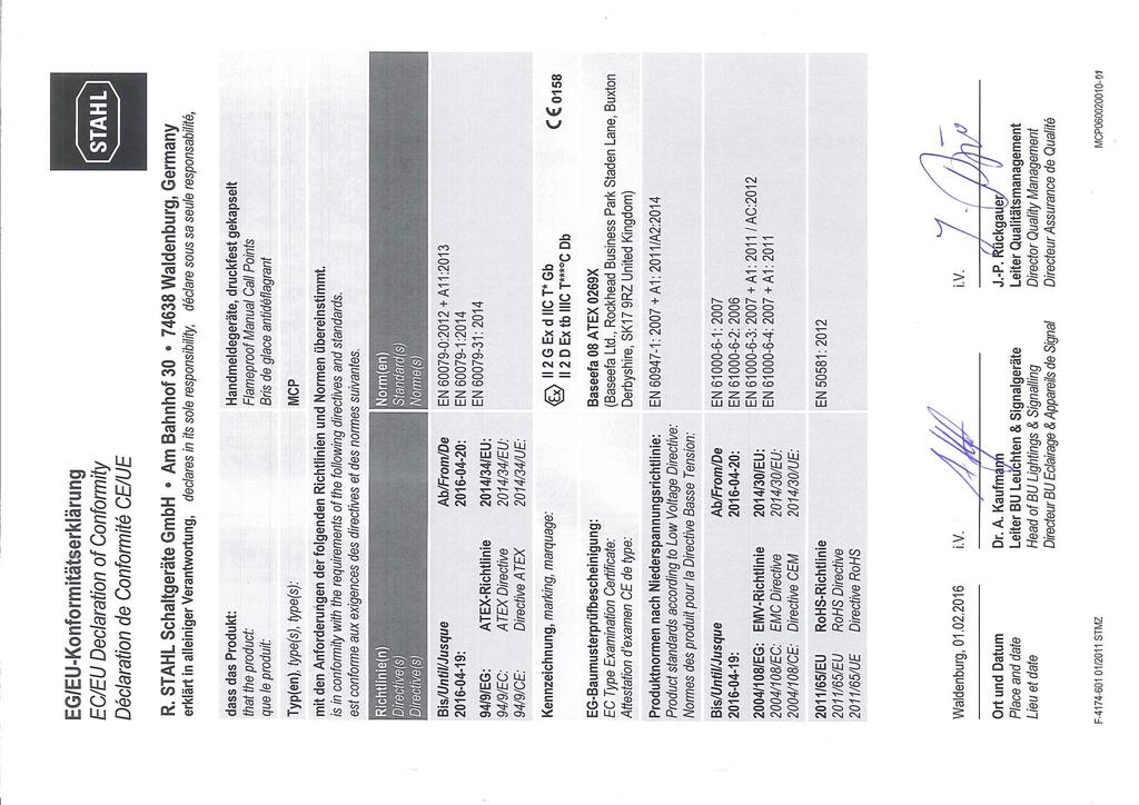
3 General Information. Manufacturer R. STAHL Schaltgeräte GmbH Business Unit Lighting & Signalling Nordstr Weimar Germany Phone: Fax: Internet: info@stahl.de. Information regarding the operating instructions ID-No.: 08 / MCP60000 Publication Code: BA00 III en 0 The original instructions are the English edition. They are legally binding in all legal affairs.. Further documents Data sheet For documents in additional languages, see General Information R. STAHL Schaltgeräte GmbH Am Bahnhof Waldenburg Germany Phone: Fax: Internet: info@stahl.de. Conformity with standards and regulations See certificates and EC Declaration of Conformity: The device has IECEx approval. For certificate please refer to the IECEx homepage: Further national certificates can be downloaded via the following link: 08 / MCP BA00 III en 0
4 Explanation of the symbols Explanation of the symbols. Symbols in these operating instructions Symbol Meaning Tips and recommendations on the use of the device General danger Danger due to explosive atmosphere Danger due to energised parts. Warning notes Warnings must be observed under all circumstances, in order to minimize the risk due to construction and operation. The warning notes have the following structure: Signalling word: DANGER, WARNING, CAUTION, NOTICE Type and source of danger/damage Consequences of danger Taking countermeasures to avoid the danger or damage DANGER Danger to persons Non-compliance with the instruction results in severe or fatal injuries to persons. WARNING Danger to persons Non-compliance with the instruction can result in severe or fatal injuries to persons. CAUTION Danger to persons Non-compliance with the instruction can result in light injuries to persons. NOTICE Avoiding material damage Non-compliance with the instruction can result in material damage to the device and / or its environment. 08 / MCP BA00 III en 0
5 Safety notes. Symbols on the device Symbol Significance CE marking according to the current applicable directive. 09E00 098E00 According to its marking, the device is certified for hazardous areas. Input 69E00 Output 68E00 08E00 Safety notes Safety instructions that must always be followed: The respective data must be noted and/or the safety-related instructions contained in the operating instructions must be followed for devices with this symbol!. Operating instructions storage Read the operating instructions carefully. Store the operating instructions at the mounting location of the device. Observe applicable documents and operating instructions of the devices to be connected.. Safe use Read and observe the safety notes in these operating instructions! Observe characteristic values and rated operating conditions on the rating and data plates! Observe additional information plates on the device! Use the device in accordance with its intended and approved purpose only! We cannot be held liable for damage caused by incorrect or unauthorized use or by non-compliance with these operating instructions. Before installation and commissioning, make sure that the device is not damaged! Work on the device (installation, maintenance, overhaul, repair) may only be carried out by appropriately authorized and trained personnel. 08 / MCP BA00 III en 0
6 Function and device design. Modifications and alterations DANGER Explosion hazard due to modifications and alterations to the device! Non-compliance results in severe or fatal injuries. Do not modify or alter the device. No liability or warranty for damage resulting from modifications and alterations. Function and device design DANGER Explosion hazard due to improper use! Non-compliance results in severe or fatal injuries. Use the device only in accordance with the operating conditions described in these operating instructions. Use the device only for the intended purpose specified in these operating instructions.. Function Application range The MCP/BG is a single or double action emergency switch. The device is designed for use in hazardous areas and/or harsh environments. In hazardous areas the device has explosion protection for ATEX /IECEx Zones and for gas and and for dust. The device is suitable for gas group IIC and dust group IIIC. Mode of operation The switch is activated by breaking the frangible glass pane on the front side of the device; this provides the user with a distinct trigger signal. The device can be equipped with a number of variants and accessories / MCP BA00 III en 0
7 Technical data Explosion Protection Global (IECEx) Gas and dust IECEx BAS X IEC : 0 / IEC : / IEC : 008 Ex d IIC T6 Ta C Gb Ex tb IIIC T8 C Ta C Db IP66 Europe (ATEX) Gas and dust Baseefa 08ATEX069X : 009 / : 007 / : 009 E II G Ex d IIC T6 Ta C Gb E II D Ex tb IIIC T8 C Ta C Db IP66 Certifications and certificates Certificates IECEx, ATEX, Brazil (INMETRO), India (PESO), Russia (TS-RU) Technical Data Electrical data Rated operational voltage Switching capacity to 0 V DC, to 0 V AC DC to 0 V A 0 to 0 V A AC to 0 V A Technical data Contact element standard: change-over contact optional: change-over contacts Switch NO or NC System test Test key provided Ambient conditions Operating -0 to +70 C temperature range Mechanical data Material Enclosure material glass fibre reinforced polyester (GRP) Surface finish two pack, acrylic polyurethane, various colour options Degree of protection IP66 acc. to IEC 609 Cable entries cable entries, supplied with (x) Ex d stopping plugs and (x) dust cap 08 / MCP BA00 III en 0 7
 indication Lift flap stainless steel (break glass version only) Duty label Metalised")
8 Transport and storage Technical Data Position of cable entries Break glass call point Connection Terminals 7 way terminal block., mm Earth connection provided as standard Accessories LED status optional: red LED status indication(up to V DC) indication Lift flap stainless steel (break glass version only) Duty label Metalised polyester, customer to specify wording / symbols (see main picture for example) Tag label Stainless steel tag with polyester label, customer to specify max 9 characters Resistors Customer to specify value Mounting / Installation Assembly via holes through the back box. see operating instruction for full details For further technical data, see 9E00 6E00 9E00 Break glass call point with lift flap 6 Transport and storage Transport and store the device only in the original packaging. Store the device in a dry place (no condensation) and vibration-free. Do not drop the device. Push button call point 7 Mounting and installation The device is approved for use in gas explosion hazardous areas of Zones and and dust explosion hazardous area of Zones and and in safe areas / MCP BA00 III en 0
9 Mounting and installation DANGER Explosion hazard due to incorrect installation of the device! Non-compliance results in severe or fatal injuries. Carry out installation strictly according to the instructions and national safety and accident prevention regulations to maintain the explosion protection. Select and install the electrical device so that explosion protection is not affected due to external influences, i.e. pressure conditions, chemical, mechanical, thermal and electric impact such as vibration, humidity and corrosion (see IEC/ ). The device must only be installed by trained qualified personnel who is familiar with the relevant standards. 7. Dimensions / fastening dimensions Dimensional drawings (All dimensions in mm [inches]) Subject to modifications MCP/BG 7. Mounting / dismounting, operating position DANGER Explosion hazard due to improper mounting! Non-compliance can result in severe or fatal injuries. Only mount the device on walls or a suitable surface. Fit the core sleeves gas-tight and only using a suitable tool. Carefully remove or replace the components. Carefully protect exposed joint surfaces from damage, dust and dirt. Install end flange without applying force (without hammer and tool) in straight alignment. 9E00 08 / MCP BA00 III en 0 9
10 Mounting and installation 7. Installation DANGER Explosion hazard due to open holes, unused cable entries and cable glands! Non-compliance can result in severe or fatal injuries. Only use approved and flameproof (Ex d) cable glands. When selecting cable entries, observe the thread type and thread size in the component documentation. Seal thread with non-hardening thread sealant. Always close unused holes, cable entries and cable glands using approved stopping plugs or plugs. Observe IEC/ for this. DANGER Danger due to energised parts! Non-compliance results in severe or fatal injuries. Before opening and dismounting the device, disconnect it from the power supply. Secure the device against unauthorized switching. Correct reassembly of the unit is required to ensure ingress protection to IP Preparation for electrical installation Cheese-head screws M x 6 MCP front cover together with middle frame PCB fastening screw PCB MCP base 66E00 Removing the cover A retaining strap is fitted between the base and front cover. Depending on the version of the selected MCP, the PCB may or may not have to be removed during installation. Details about this can be found in the "Electrical connection" chapter. Remove screws. Lift the MCP front cover together with the middle frame / MCP BA00 III en 0
11 Mounting and installation Re-assembly of the enclosure If removed, replace PCB and screws. Replace the front cover with the middle frame. Ensure that the retraining strap is not pinched in. Once the front cover is in position, tighten the outer screws with a torque of 6. Nm. 7.. Electrical Connection Key components 7.. Circuit diagrams LK LK N/C N/O Common LK The device is to be installed on a wall made from a suitable material! Comply with local directives and standards when selecting the installation location! Correct reassembly of the device is required to ensure the degree of protection. Be cautious when replacing components and ensure the correct torque is applied, where specified. 6 68E00 Cable connection (from left) Connection for switch LK, LK and LK connections for special versions PCB fastening points Terminal block 6 Breakable lugs for independent switch function MCP switch can be operated normally open or normally closed to suit different systems. The device can be purchased with a single or two-pin switch. Two-pin switch can be used as standard or to switch independent circuits. An LED indication light is available as an optional extra. Standard wiring configurations are listed below. If further information is required please contact your local sales office. 08 / MCP BA00 III en 0
12 Mounting and installation 7.. Standard devices Single-pole MCP, switch normally open in standby / normally closed in alarm Single-pole MCP, switch normally closed in standby / normally open in alarm Two-pole MCP, switch normally open in standby / normally closed in alarm (independent circuits) Two-pole MCP, switch normally closed in standby / normally open in alarm (independent circuits) LK N/C N/O Common LK LK N/C N/O Common LK LK N/C N/O Common LK LK N/C N/O Common LK 68E00 686E00 687E00 Cable connection (from left) L / + N / - Cable connection (from left) L / + N / - Cable connection (from left) L / + pole L / + pole N / - pole N / - pole Cable connection (from left) L / + pole L / + pole N / - pole N / - pole 688E Standard devices with monitoring resistors Standard versions with monitoring resistors are only available with switch normally closed in standby / normally open in alarm. Resistor values are to be selected by the system designer, depending on requirements. The PCB has 0 ohms of resistance. For V DC systems, a minimum resistor value of 70 ohms should be used. 08 / MCP BA00 III en 0
13 Mounting and installation Single-pole MCP, switch normally closed in standby / normally open in alarm Make sure that the LK connection has been removed. In-line resistor between positions & 6 R. End-of-line resistor between positions & R Standard devices with LED status light Single-pole MCP, switch normally open in standby / normally closed in alarm 006E00 08E00 Normal / standby Switch closed end-of-line resistor active N / - L / + R end-of-line resistor R in-line resistor Active / alarm Switch open in-line resistor engaged N / - L / + R end-of-line resistor R in-line resistor There is an 80 ohm resistor which is in line with the LED. When activated, the LED together with the resistor will draw a current. On a V DC system this current is approximately 0 ma. a a a a C 767E00 Ensure that the connector wires from switch and LED are correctly installed as per the schematic (see the following figure). 08 / MCP BA00 III en 0
14 Mounting and installation Remove LK for LED activation in alarm or remove LK for LED activation in standby. Add a jumper/connection between terminals and. Terminal is the one closest to LK. The jumper/connection is depicted in the figure. Single-pole MCP, switch normally closed in standby / normally open in alarm a a a a LK LK N/C N/O Common LK C 76E00 76E00 767E00 Ensure that the connector wires from switch and LED are correctly installed as per the schematic (see the following figure). C a Connector terminal Red wire for LED Black wire for LED Blue wire for switch Yellow wire for switch Red wire for switch Cable connection (from left) L / + N / - C a Connector terminal Red wire for LED Black wire for LED Blue wire for switch Yellow wire for switch Red wire for switch 76E00 LK LK N/C N/O Cable connection (from left) L / + N / - Common LK 76E00 08 / MCP BA00 III en 0
15 Mounting and installation Remove LK for LED activation in alarm or remove LK for LED activation in standby. Add a jumper/connection between terminals and. Terminal is the one closest to LK. The jumper/connection is depicted in the figure. Two-pole MCP, switch normally open in standby / normally closed in alarm (independent circuits) a a a a 767E00 Ensure that the connector wires from switch and LED are correctly installed as per the schematic (see the following figure). LK LK N/C N/O Common LK C 766E00 C a a a a Connector terminal Red wire for LED Black wire for LED Blue wire for switch Blue wire for second switch Yellow wire for switch Yellow wire for second switch Red wire for switch Red wire for second switch Cable connection (from right) L / + L / + N / - N / - Remove LK for LED activation in alarm or remove LK for LED activation in standby. Add a jumper/connection between terminals and. Terminal is the one closest to LK. The jumper/connection is depicted in the figure. Two-pole MCP, switch normally closed in standby / normally open in alarm (independent circuits) 766E00 a a a a C 767E00 Ensure that the connector wires from switch and LED are correctly installed as per the schematic (see the following figure). 08 / MCP BA00 III en 0
16 Mounting and installation LK LK N/C N/O Common LK Remove LK for LED activation in alarm or remove LK for LED activation in standby. Add a jumper/connection between terminals and. Terminal is the one closest to LK. The jumper/connection is depicted in the figure Standard devices with monitoring resistors and LED status light 766E00 767E00 C a a a a Connector terminal Red wire for LED Black wire for LED Blue wire for switch Blue wire for second switch Yellow wire for switch Yellow wire for second switch Red wire for switch Red wire for second switch Cable connection (from right) L / + L / + N / - N / - standard versions with monitoring are only available with switch normally closed in standby / normally open in alarm with LED activated. There is an 80 ohm resistor which is in-line with the LED. When activated, the LED together with the resistor will draw a current. On a V DC system this current is approximately 0 ma. In standby without the LED activated, the resistance of the the PCB is 0 ohms. Resistor values are to be selected by the system designer, depending on the system requirements. For V DC systems, a minimum resistor value of 70 ohms should be used. Single-pole MCP, switch normally closed in standby / normally open in alarm a a a a C 767E00 Ensure that the connector wires from switch and LED are correctly installed as per the schematic (see the following figure) / MCP BA00 III en 0
17 R R R R 78E00 7E00 7E00 C a a Make sure that the LK connection has been removed. In-line resistor between positions & 6 R. End-of-line resistor between positions & R. Connector terminal Black wire for LED Blue wire for switch Yellow wire for switch Red wire for switch Red wire for LED Mounting and installation Normal / standby Switch closed end-of-line resistor engaged N / - L / + Active / alarm Switch open in-line resistor engaged N / - L / Earth connection 66E00 08 / MCP BA00 III en 0 7
18 Commissioning 8 Commissioning Before commissioning, ensure the following: Check the mounting and installation. Enclosure must not be damaged. If necessary, remove foreign bodies. If necessary, clean the connection chamber. Check if the conductors have been inserted correctly. Check if all screws and nuts have been tightened firmly. Check if all conductors have been clamped firmly. Check if all prescribed tightening torques have been observed. Check whether the bayonet lock is tightened firmly. Make sure that the plug pin surface is not damaged. Use only in completely mounted state. 9 Operation DANGER Explosion hazard due to incorrect installation! Non-compliance results in severe or fatal injuries. Check the device for proper installation before commissioning. Comply with national regulations. 9. Manual signalling device test Insert the key. 66E00 Trip an alarm: Carefully turn the key clockwise until the alarm is triggered. 667E / MCP BA00 III en 0
19 9. Resetting the manual signalling device Key components A B 67E00 A B 68E00 CAUTION Danger of cutting injuries due to broken glass! Non-compliance can result in light injuries. Wear protective gloves. Operation Test completed: Turn the key back to its home position. The manual signalling device is ready to be used again. Mounting hinge for the frangible glass pane Recess Recess Piston Lever under spring tension Pivot point for the glass pane Pivot point for the glass pane Remove the screws. 670E00 Insert the key and turn clockwise by. Lift the front cover with the inserted key. 667E00 08 / MCP BA00 III en 0 9
20 Operation Remove the front cover from the device. Remove the broken glass pane. 67E00 67E00 Position the new glass pane carefully, as shown in the figure. Important: The lower edge of the glass pane must lie on the mounting hinge. The piston must push the glass pane down. The glass pane must be installed facing in the direction that is depicted in the figure. Insert the key bit through the opening in the front cover of the device. 67E00 Important: The key bit must be in the direction of the lever home position (). Place the key together with the front cover onto the device. The key is now located in the lever and the front cover is blocked by the piston. Turn the key clockwise by. The piston rises and the front cover slips onto the device / MCP BA00 III en 0
21 9. Troubleshooting If the error cannot be eliminated using the mentioned procedures: Contact R. STAHL Schaltgeräte GmbH. For fast processing, have the following information ready: Type and serial number of the device Purchase information Error description Intended use (in particular input / output wiring) 0 Maintenance, Overhaul, Repair 669E00 677E00 Maintenance, Overhaul, Repair Remove the key. Insert the screws and tighten them. CAUTION Risk of electric shock or malfunction of the device due to unauthorized work! Non-compliance can result in light injuries! Before carrying out work on the device, switch off voltage supply. Work performed on the device must only be carried out by authorized and appropriately trained qualified electricians. 08 / MCP BA00 III en 0
22 Maintenance, Overhaul, Repair 0. Maintenance Determine the type and extent of inspections in compliance with the relevant national regulations. Adapt inspection intervals to the operating conditions. The following tests and measures must be carried out during regular maintenance. 0. Repair Observe the relevant national regulations in the country of use. Check the permissible ambient temperature the enclosure components for formation of cracks and damage. its intended use if the conductors are clamped properly the cables for ageing and damage the seals for ageing and damage Measures If exceeding the permissible ambient temperature or falling below the device must be taken out of operation. Replace the exchangeable enclosure components. If the enclosure components are non-exchangeable, the device must be taken out of operation. If the device is not used according to its intended use, it must be taken out of operation. clamp loose conductors tightly. replace damaged or aged cables. replace damaged, aged and porous seals and completely change enclosure components with foamed seal. DANGER Explosion hazard due to improper repair! Non-compliance results in severe or fatal injuries. Repair work on the devices must be performed only by R. STAHL Schaltgeräte GmbH. 08 / MCP BA00 III en 0
23 0. Returning the device Only return or package the devices after consulting R. STAHL! Contact the responsible representative from R. STAHL. Cleaning R. STAHL's customer service is available to handle returns if repair or service is required. Contact customer service personally. or Go to the website. Under "Support" > "RMA form", select "Request RMA slip". Fill out the form and send it. Confirmation will be sent. R. STAHL's customer service will contact you. You will receive an RMA slip after speaking with customer service. Send the device along with the RMA slip in the packaging to R. STAHL Schaltgeräte GmbH (refer to Section. for the address). Cleaning Clean the device only with a cloth, brush, vacuum cleaner or similar items. When cleaning with a damp cloth, use water or mild, non-abrasive, non-scratching cleaning agents. Do not use aggressive detergents or solvents. Disposal Observe national and local regulations and statutory regulation regarding disposal. Separate materials when sending it for recycling. Ensure environmentally friendly disposal of all components according to the statutory regulations. Accessories and Spare parts NOTICE Malfunction or damage to the device due to the use of non-original components. Non-compliance can result in material damage. Use only original accessories and spare parts from R. STAHL Schaltgeräte GmbH. For accessories and spare parts, see data sheet on our homepage 08 / MCP BA00 III en 0
24
Inspection Light LED 6149/2. Operating instructions EN EN EN EN EN EN EN EN EN EN EN EN EN EN EN EN EN EN EN EN EN EN EN EN
 Inspection Light LED Operating instructions Additional languages www.stahl-ex.com Contents 1 General Information...3 1.1 Manufacturer...3 1.2 Information regarding the operating instructions...3 1.3 Conformity
Explosion Proof Combination Signal db (A) / 5 Joule
 / 5 Joule") Explosion Proof Combination Signal - Operating instructions Additional languages www.r-stahl.com General information Contents 1 General information...2 1.1 Manufacturer...2 1.2 Information regarding the
Explosion Proof Combination Signal - Operating instructions Additional languages www.r-stahl.com General information Contents 1 General information...2 1.1 Manufacturer...2 1.2 Information regarding the
Flameproof Manual Call Points Series MCP
 > Light weight glass reinforced polyester (GRP) Ex d enclosure > Weather resistant high performance red paint finish as standard > Break glass version supplied with test key > Push button version supplied
Flameproof Manual Call Points Series MCP
 > Light weight glass reinforced polyester (GRP) Ex d enclosure > Weather resistant high performance red paint finish as standard > Break glass version supplied with test key > Push button version supplied
Explosion Proof Manual Call Points Series MCP
 > Light weight glass reinforced polyester (GRP) Ex d enclosure > Weather resistant high performance red paint finish as standard > Break glass version supplied with test key > Push button version supplied
INSTRUCTION MANUAL (ATEX / IECEx)
") INSTRUCTION MANUAL (ATEX / IECEx) BExS110D and BExS110D-R Sounder For use in Flammable Gas and Dust Atmospheres BExS110D BExS110D-R 1) Warnings DO NOT OPEN WHEN AN EXPLOSIVE ATMOSPHERE IS PRESENT DO NOT
INSTRUCTION MANUAL (ATEX / IECEx) BExS110D and BExS110D-R Sounder For use in Flammable Gas and Dust Atmospheres BExS110D BExS110D-R 1) Warnings DO NOT OPEN WHEN AN EXPLOSIVE ATMOSPHERE IS PRESENT DO NOT
GRP Flameproof Combination Signal db(a) / 5 Joule Series YL6S
 / 5 Joule Series YL6S") www.stahl.de > Corrosion resistant omnidirectional high output sounder > Integrated Ex d enclosure > Extreme temperature range > 3 stage alarm with independant tone selection for V DC systems > IP66 IP67
www.stahl.de > Corrosion resistant omnidirectional high output sounder > Integrated Ex d enclosure > Extreme temperature range > 3 stage alarm with independant tone selection for V DC systems > IP66 IP67
Operating Instructions
 Important information: These instructions contain safety information, read and follow them carefully. Dialight will not accept any responsibility for injury, damage or loss which may occur due to incorrect
Additional Operating Instructions SITRANS F. Vortex flowmeters. SITRANS FX330 Ex-d.
 Additional Operating Instructions SITRANS F Vortex flowmeters Ex-d Edition 09/208 CONTENTS Safety instructions 3. General notes... 3.2 EU conformity... 3.3 Approval according to the IECEx scheme... 3.4
Integrated Solutions Low Voltage Systems
 Integrated Solutions Low Voltage Systems 612 Contents Energy Distribution Overview Module Technology 8146 614 Overview Flameproof Enclosures 8220 614 Overview Flameproof Enclosures 8261 614 Overview CUBEx
Duct heaters for ATEX/IECEx hazardous areas or in non-atex version
 for ATEX/IECEx hazardous areas or in non-atex version * Non contractual picture Warning It is imperative to read these instructions carefully before installing or maintaining the equipment. MI200EN 09/2017
VERSAFLOW VORTEX Supplementary instructions
 VERSAFLOW VORTEX Supplementary instructions Vortex flowmeter Equipment category II 2G CONTENTS VERSAFLOW VORTEX 1 Safety instructions 3 1.1 General notes... 3 1.2 EC conformity... 3 1.3 Approval according
Immersion heaters for ATEX/IECEx hazardous areas or in non-atex version
 for ATEX/IECEx hazardous areas or in non-atex version * Non contractual picture Warning It is imperative to read these instructions carefully before installing or maintaining the equipment. MI100EN 09/2017
Installation manual surface mounting plugs and socket outlets, panel mounting plugs and socket outlets with screw connection (16/32 A)
") EN Installation manual surface mounting plugs and socket outlets, panel 60003214 Issue 04.2016 2016-04-01 Table of contents 1 About this manual 3 1.1 Structure of the warnings 3 1.2 Symbols used 4 1.3
EN Installation manual surface mounting plugs and socket outlets, panel 60003214 Issue 04.2016 2016-04-01 Table of contents 1 About this manual 3 1.1 Structure of the warnings 3 1.2 Symbols used 4 1.3
Regulated Ex-Heater HEX with internal controller, HEX with external controller II 3 G II 3 D
 Regulated Ex-Heater HEX5-1.08 with internal controller, HEX5-2.08 with external controller II 3 G II 3 D Instruction Manual Version 1.02.00 Dear customer, we have made up this operating manual in such
Installation manual extra-low-voltage socket outlets for panel- and surface-mounting
 EN Installation manual extra-low-voltage socket outlets for panel- and 60003221 Issue 04.2016 2016-04-01 Table of contents 1 About this manual 3 1.1 Structure of the warnings 3 1.2 Symbols used 4 1.3 Signal
Earth-Rite II PLUS Static Earthing System
 READ MANUAL BEFORE COMMENCING WITH INSTALLATION EN Earth-Rite II PLUS Static Earthing System P1 PLUS - DC Supply Installation & Operating Instructions The safety of any system incorporating the equipment
Global Series. Installation and Maintenance Instructions. Model G-STR Strobe Beacon. For Use in Hazardous Locations
 Global Series Model G-STR Strobe Beacon For Use in Hazardous Locations Ex d Surface Mount Ex de Surface Mount Installation and Maintenance Instructions 25500185 Rev. B4 1217 Printed in U.S.A. Limited Warranty
Circulation heaters for ATEX/IECEx hazardous areas or in non-atex version
 for ATEX/IECEx hazardous areas or in non-atex version * Non contractual picture Warning It is imperative to read these instructions carefully before installing or maintaining the equipment. MI500EN 09/2017
Additional Operating Instructions SITRANS F. Vortex flowmeters. SITRANS FX330 Ex-i.
 Additional Operating Instructions SITRANS F Vortex flowmeters Ex-i Edition 09/2018 CONTENTS 1 Safety instructions 3 1.1 General notes... 3 1.2 EU conformity... 3 1.3 Approval according to the IECEx scheme...
OPTIWAVE X500 Supplementary Instructions
 OPTIWAVE X500 Supplementary Instructions OPTIWAVE 3500 C OPTIWAVE 6500 C OPTIWAVE 7500 C Supplementary Instructions for ATEX applications KROHNE CONTENTS OPTIWAVE X500 1 General safety information 4 1.1
INSTRUCTION MANUAL (ATEX/IECEx/SIL2) BExBG05D-SIL Flameproof Xenon SIL 2 Beacons For use in Flammable Gas and Dust Atmospheres
 BExBG05D-SIL Flameproof Xenon SIL 2 Beacons For use in Flammable Gas and Dust Atmospheres") INSTRUCTION MANUAL (ATEX/IECEx/SIL2) BExBG05D-SIL Flameproof Xenon SIL 2 Beacons For use in Flammable Gas and Dust Atmospheres 1) Introduction The BExBG05D-SIL is a flameproof beacon which is certified
INSTRUCTION MANUAL (ATEX/IECEx/SIL2) BExBG05D-SIL Flameproof Xenon SIL 2 Beacons For use in Flammable Gas and Dust Atmospheres 1) Introduction The BExBG05D-SIL is a flameproof beacon which is certified
Translation of the assembly instructions with operating instructions and technical appendix
 BA Ex-SBU Switch box type SBU-x(1,2,3)x Translation of the assembly instructions with operating instructions and technical appendix In accordance with EU ATEX Directive 2014/32/EU In accordance with EU
Instruction Manual. Alarm Unit For Low Gas Level # Read manual before use! Observe all safety information! Keep manual for future use!
 Mess-, Regel- und Überwachungsgeräte für Haustechnik, Industrie und Umweltschutz Lindenstraße 20 74363 Güglingen Telefon +49 7135-102-0 Service +49 7135-102-211 Telefax +49 7135-102-147 info@afriso.de
Approved by: Document no.: EGT
 ET Page 1 of 6 TECHNICL MNUL EXPLOSION PROOF MNUL CLL POINT / PUSH BUTTON TEX Marking: Code: II 2D EPL b, Db Ex d IIC T6 IP66 Ex tb IIIC T85 C Marking details: Please note that every care has been taken
standards: standards:
 INSTRUCTION MANUAL D2xB1LD2 LED Beacons For use in Hazardous Locations 1) Warnings DO NOT OPEN WHEN AN EXPLOSIVE ATMOSPHERE IS PRESENT DO NOT OPEN WHEN ENERGISED POTENTIAL ELECTROSTATIC CHARGING HAZARD
Installation manual plugs and connectors QUICK-CONNECT (63 A)
") EN Installation manual plugs and connectors QUICK-CONNECT (63 A) 60003217 Issue 04.2016 2016-04-01 Table of contents 1 About this manual 3 1.1 Structure of the warnings 3 1.2 Symbols used 4 1.3 Signal
EN Installation manual plugs and connectors QUICK-CONNECT (63 A) 60003217 Issue 04.2016 2016-04-01 Table of contents 1 About this manual 3 1.1 Structure of the warnings 3 1.2 Symbols used 4 1.3 Signal
Sensor module. Operating instructions. Sensor module, Type 17-51P2-... Document No P2-7D0001 Version: 17 May 2011/Rev. 0
 Sensor module Operating instructions Sensor module, Document No. 11-51P2-7D0001 Version: 17 May 2011/Rev. 0 Operating Instructions Sensor-Module Type: 17-51P2-. Document no.: 11-51P2-7D0001 Version: 17.
Operating instructions
 ebm-papst Mulfingen GmbH & Co. KG Bachmühle D-74673 Mulfingen Phone +49 (0) 793-0 Fax +49 (0) 793-0 info@de.ebmpapst.com www.ebmpapst.com CONTENTS. SAFETY REGULATIONS AND NOTES. Levels of hazard warnings.
Manual Power relay SR853
 Manual Power relay SR853 Product types SR853.8.x.x, Rev. 1 SR853 manual page2 The symbols WARNING, CAUTION, NOTE This symbol warns of a serious hazard. Failure to observe this warning may result in death
INSTRUCTION MANUAL. E2xB05 & E2xB10 Xenon Beacons For use in Hazardous Locations
 INSTRUCTION MANUAL E2xB05 & E2xB10 Xenon Beacons For use in Hazardous Locations 1) Warnings DO NOT OPEN WHEN AN EXPLOSIVE ATMOSPHERE IS PRESENT DO NOT OPEN WHEN ENERGISED POTENTIAL ELECTROSTATIC CHARGING
SCHMIDT Flow Sensor SS Ex - Supplementary instructions for use in explosive atmospheres ATEX
 SCHMIDT Flow Sensor SS 20.600 Ex - Supplementary instructions for use in explosive atmospheres ATEX SCHMIDT Flow Sensor SS 20.600 Ex ATEX version Table of Contents 1 Important information... 3 2 Storage
LIGHTING TEF 9980 STATUS LIGHT, MAIN LIGHT & REPEATER LIGHT ZONE 1, ZONE 2 & SAFE AREA USER MANUAL
 Subject to change without prior notice TUM7 REV. B.08.08 SAFETY INSTRUCTIONS The TEF 9980 status light may be installed in Zone, or safe area. The Equipment shall not be installed in Zone 0! HANDLE WITH
TECHNICAL MANUAL EXPLOSION PROOF STATUS LIGHT / LAMP BSL 125 / BSL 150. Scope: EXcite USER MANUAL BSL 125 / BSL 150. Date:
 Page 1 of 9 TECHNICL MNUL EXPLOSION PROOF STTUS LIGHT / LMP TEX Marking: Code: II 2GD EPL Gb, Db Ex d IIC T4/T5/T6 IP66 Ex tb IIIC TXXX C Marking details: Please note that every care has been taken to
IECEx Certificate. INTERNATIONAL ELECTROTECHNICAL COMMISSION IEC Certification Scheme for Explosive Atmospheres
 INTERNATIONAL ELECTROTECHNICAL COMMISSION IEC Certification Scheme for Explosive Atmospheres for rules and details of the IECEx Scheme visit www.iecex.com Certificate No.: Certificate history: Status:
Multiple Status Indicators Series MEXE, MS25, MS35, MS45, MS55
 www.stahl.de > Pre-wi ready-to-use multi-signalling unit > Corrosion resistant > Suitable for offshore / onshore harsh environments > Incorporates the FX15 GRP beacon YA90 for visual audible notification
Installation manual surface mounting plugs and socket outlets, panel mounting plugs and socket outlets QUICK-CONNECT (63 A)
") EN Installation manual surface mounting plugs and socket outlets, panel 60003506 Issue 04.2016 2016-04-01 Table of contents 1 About this manual 3 1.1 Structure of the warnings 3 1.2 Symbols used 4 1.3
EN Installation manual surface mounting plugs and socket outlets, panel 60003506 Issue 04.2016 2016-04-01 Table of contents 1 About this manual 3 1.1 Structure of the warnings 3 1.2 Symbols used 4 1.3
Explosion Proof Combination Signal db (A) / 5 Joule Series YL60
 / 5 Joule Series YL60") www.stahl.de Explosion Proof Combination Signal - 110 db (A) / 5 Joule > Omnidirectional high output sounder 110 db (A) / 1 m > 5 Joule xenon strobe > 2 stage alarm, independently selectable 2nd stage
www.stahl.de Explosion Proof Combination Signal - 110 db (A) / 5 Joule > Omnidirectional high output sounder 110 db (A) / 1 m > 5 Joule xenon strobe > 2 stage alarm, independently selectable 2nd stage
Additional Operating Instructions SITRANS F. Vortex flowmeters. SITRANS FX330 Ex-nA.
 Additional Operating Instructions SITRANS F Vortex flowmeters Ex-nA Edition 08/207 CONTENTS Safety instructions 3. General notes... 3.2 EU conformity... 3.3 Approval according to the IECEx scheme... 3.4
EX-TECH SIGNALLING SAS SD100-1 WEATHERPROOF SOUNDER/HORN TECHNICAL MANUAL
 PRODUCT NAME: SD-100-1- WEATHER-PROOF SOUNDER/HORN DOC NO.: EX-TECH SIGNALLING SAS-12-SD100-1-TM REV03 WEATHERPROOF SOUNDER/HORN IP66 SD-100 SERIES EX-TECH SIGNALLING SAS SD100-1 WEATHERPROOF SOUNDER/HORN
SPECIFICATION SHEET. Installation, Operation, Maintenance Instructions for safety use Series EX SOCKET SWITCH
 Page /3 SPECIFICATION SHEET Ed. Document UTE_ Issued Written Verified Approved MP36350 6-05-05 Strizzi Franco Page /3 INDICE HISTORY... 3 MODIFY RECORDING... 3 INSTALLATION, OPERATION AND MAINTENANCE INSTRUCTIONS
OPTIBAR DP 7060 Supplementary Instructions
 OPTIBAR DP 7060 Supplementary Instructions Differential pressure transmitter Category ATEX II 1/2G, 2G Ex db ia IIC T6...T1 Ga/Gb, Gb IECEx Ex db ia IIC T6...T1 Ga/Gb, Gb Housing Aluminium: Single chamber,
INSTRUCTION MANUAL. D2xB1XH1 & D2xB1XH2 Xenon Beacons For use in Hazardous Locations
 INSTRUCTION MANUAL D2xB1XH1 & D2xB1XH2 Xenon Beacons For use in Hazardous Locations synchronization requirements of UL1971 & UL1638 / CAN/ULCS526. 2.2 NEC & CEC Class / Division Ratings for US / Canada
COMPACT FLAME CONTROLLER CFC 200 (Formerly 8.XX)
") COMPACT FLAME CONTROLLER CFC 200 (Formerly 8.XX) TECHNICAL DESCRIPTION EDITION: TB CFC200-REV3-2015-04-07 IMPORTANT: Please note, that all mounting and wiring as well as all changing or adjustment at the
COMPACT FLAME CONTROLLER CFC 200 (Formerly 8.XX) TECHNICAL DESCRIPTION EDITION: TB CFC200-REV3-2015-04-07 IMPORTANT: Please note, that all mounting and wiring as well as all changing or adjustment at the
FSW300 Series Flow Switch
 . FSW300 Series Flow Switch - 2 - Series FSW300 Series FSW300 Table of contents page 0 About this operating manual... 4 1 Device description... 5 1.1 Intended use... 5 1.1.1 Reed contact - Switching of
EJBX. Ex d. AISI 316L stainless steel. - Zone 1, 2, 21, 22 - Group IIB+H2 - Stainless steel junction boxes - Choice of 13 sizes - IP 66 / 67
 Ex d EJBX AISI 316L stainless steel - Zone 1, 2, 21, 22 - Group IIB+H2 - Stainless steel junction boxes - Choice of 13 sizes - IP 66 / 67 Quartz sand blasting Warning labels Mounting bracket Silicone gasket
BKA-EN Fire Damper. Additional operating instructions according to
 Additional operating instructions according to BKA-EN Fire Damper Contents GENERAL CONDITIONS... 1 DESCRIPTION... 3... 4 EC Certificate of Conformity 0761 CPD 0244 Declaration of Performance 09-19-DoP-BKA-EN-2013-07-01
Safety. Operating instructions UV sensor UVS 10 DANGER WARNING. Contents CAUTION Edition Please read and keep in a safe place
 8.. Edition 08.0 D GB F NL I E DK S N P GR TR CZ PL RUS H www.docuthek.com Operating instructions UV sensor UVS 0 Translation from the German 008 009 Elster GmbH Contents UV sensor UVS 0......................
Officine Meccaniche M.A.M. series for command, control, signaling and/or automation. DOCUMENT IS-EJB-A-14 rev. 0
 Officine Meccaniche M.A.M. Apparecchiature Antideflagranti DOCUMENT IS-EJB-A-14 rev. 0 Instructions Flameproof enclosures EJB../W series for command, control, signaling and/or automation Emission date:
OPTIBAR P 1010/2010 C Supplementary instructions
 OPTIBAR P 1010/2010 C Supplementary instructions Pressure transmitter Equipment category II 1G / Ga, II 1D / Da in protection type intrinsic safety Exi KROHNE CONTENTS OPTIBAR P 1010/2010 C 1 Safety instructions
USER MANUAL FOR EXPLOSION PROTECTED FLUORESCENT LIGHT FITTING type PSF 218
 CONTENT 1. Manufacturer 1 2. General safety informations 1 3. Purpose 2 4. Product compliance 2 5. Degree of protection and technical data 2 6. Type 3 7. Mounting and installation 3 8. Dimensions 6 9.
INSTRUCTION & SERVICE MANUAL
 INSTRUCTION & SERVICE MANUAL D2xC1 ALARM HORN AND STROBE For Use In Hazardous Locations 3) Ratings and Markings 3.1 ATEX / IECEx certification The D2xC1 Alarm Horn and Strobe complies with the following
Certificate of Compliance
 FF0 001 Certificate of Compliance Certificate: 70116279 (LR 025993_0_000) Issued to: General Monitors, Incorporated 26776 Simpatica Circle Lake Forest, California 92630 USA Attention: Larry Vlagea The
DSF xx15.xx xhv Ex-Atex Ex-Atex Certified Two wire Hall Effect Speed Sensor
 DSF xx15.xx xhv Ex-Atex Product ID Type # Product # Drawing # DSF 1215.01 SHV Ex-atex (5m) 304Z-05197 113216 DSF 1415.01 AHV Ex-atex S148 304Z-05256 113351 DSF 1615.01 SHV Ex-atex (5m) 304Z-05196 113214
INSTRUCTION MANUAL IS-mB1 Minialite Intrinsically Safe Round LED Beacon
 INSTRUCTION MANUAL Minialite Intrinsically Safe Round LED This instruction sheet describes installations which conform to EN60079:Part14:2008 Electrical Installation in Hazardous Areas. When designing
Operating manual GTL 369 GTL 369M GTL 389 GTL 389M. Temperature probe. Please keep the manual for future use.
 Operating manual Temperature probe GTL 369 GTL 369M GTL 389 GTL 389M Please keep the manual for future use. L02.0.3X.6C-01 GREISINGER electronic GmbH Hans-Sachs-Str. 26 93128 Regenstauf Germany Fon +49(0)9402-9383-0
User Manual GV25 GV35 GV702. Company information: Original instructions GV12066 (1)
") User Manual Original instructions GV25 GV35 GV702 Company information: www.vipercleaning.eu info-eu@vipercleaning.com GV12066 (1) 2012-04-10 USER MANUAL ENGLISH TABLE OF CONTENTS Introduction... 4 Manual
User Manual Original instructions GV25 GV35 GV702 Company information: www.vipercleaning.eu info-eu@vipercleaning.com GV12066 (1) 2012-04-10 USER MANUAL ENGLISH TABLE OF CONTENTS Introduction... 4 Manual
2CKA001473B System Manual Busch-Infoline. Handicapped toilet signal set 1510 UC
 2CKA001473B9007 19.05.2017 System Manual Busch-Infoline Handicapped toilet signal set 1510 UC-... -101 Table of contents Table of contents 1 Notes on the instruction manual... 3 2 Safety... 4 2.1 Information
BSK-RPR Fire Damper. Additional operating instructions according to
 Additional operating instructions according to BSK-RPR Fire Damper Contents GENERAL CONDITIONS... 1 DESCRIPTION... 3... 4 EC Certificate of Conformity 0761 CPD 0245 Declaration of Performance 09-22-DoP-BSK-RPR-2013-07-01
INSTRUCTION MANUAL (ATEX/IECEx/SIL2)
") INSTRUCTION MANUAL (ATEX/IECEx/SIL2) BExS110D-SIL Flameproof Sounders For use in Flammable Gas Atmospheres BExS110D-SIL 1) Warnings DO NOT OPEN WHEN AN EXPLOSIVE ATMOSPHERE IS PRESENT DO NOT OPEN WHEN
INSTRUCTION MANUAL (ATEX/IECEx/SIL2) BExS110D-SIL Flameproof Sounders For use in Flammable Gas Atmospheres BExS110D-SIL 1) Warnings DO NOT OPEN WHEN AN EXPLOSIVE ATMOSPHERE IS PRESENT DO NOT OPEN WHEN
INSTALLATION OPERATION AND MAINTENANCE INSTRUCTIONS FAW, FAW-C & FAW-C-T TYPE AIR WARMERS FCR & FCR-A TYPE CONVECTORS
 INSTALLATION OPERATION AND MAINTENANCE INSTRUCTIONS FAW, FAW-C & FAW-C-T TYPE AIR WARMERS FCR & FCR-A TYPE CONVECTORS STW & STW-T SAFE AREA AIR WARMERS HFT, AFT & SAT TYPE AIR THERMOSTATS Please read these
Installation and operating instructions. DK energy storage and DK energy buffer
 Installation and operating instructions DK energy storage and DK energy buffer Edition: 08-2015 1 Preliminary note With this DK energy storage / DK energy buffer you purchased a DK quality product. The
Read this manual through carefully before installing/using the cleaner, paying special attention to the SAFETY INSTRUCTIONS
 PW1370TD 2 EN Read this manual through carefully before installing/using the cleaner, paying special attention to the SAFETY INSTRUCTIONS 3 E3 E1 C3 A1-A2-A3-A4 B4 B1 B5 B2 C1 B3 D 1 4 1 2 3 4 5 6 7 Ø13
DSF xx10.xx xhv Ex-Atex Hall Effect Single Channel Speed Sensor
 Product ID Type # Product # Drawing # DSF 1210.00 SHV Ex-atex (2m) 374Z-05066 110428F1 DSF 1210.00 SHV Ex-atex (5m) 374Z-05176 110428F1 DSF 1210.00 SHV Ex-atex (10m) 374Z-05590 110428F1 DSF 1410.00 SHV
ATM Lighting sp. z o.o
 INSTALLATION AND MAINTENANCE MANUAL FOR EXPLOSIONPROOF LIGHT FITTING EXL210LED Carefully read the instructions before mounting the light fitting. ATM Lighting sp. z o.o., ul. Budowlanych 31, 80-298 Gdańsk,
OilSET Installation and Operating Instructions. Oil Separator Alarm Device
 Labkotec Oy Myllyhaantie 6 FI-33960 PIRKKALA FINLAND Tel: +358 29 006 260 Fax: +358 29 006 1260 18.11.2010 Internet: www.labkotec.fi 1/10 OilSET-1000 Oil Separator Alarm Device Copyright 2010 Labkotec
Technical Manual for the Alarm Pull Station PH1
 Technical Manual for the Alarm Pull Station PH1 Please note that every care has been taken to ensure the accuracy of our technical manual. We do not, however, accept responsibility for damage, loss or
Multipoint temperature sensor
 Multipoint temperature sensor ATEX e / t for use in areas with an explosion hazard Persons concerned: Experienced professional electricians as per EU Directive 1999/92/EC and trained personnel B 903530.0.0
OilSET Installation and Operating Instructions. Oil Separator Alarm Device with SET/DM3AL sensor
 Labkotec UK Ltd Adminicle House 1 Lumb Lane Audenshaw Manchester M34 5WH GREAT BRITAIN Tel: 0844 3350 477 Fax: 0161 4281 179 E-mail: info@labkotec.co.uk 10.8.2012 Internet: www.labkotec.co.uk 1/13 OilSET-1000
Operating instructions Electric agitator RE80Ex. T-Dok-520-GB-Rev.5 Article no Translation of the original operating instructions
 GB Operating instructions Electric agitator RE80Ex T-Dok-520-GB-Rev.5 Article no. 200-0332 Translation of the original operating instructions Thank you for selecting a Krautzberger product. This product
ATM Lighting sp. z o.o
 INSTALLATION AND MAINTENANCE MANUAL FOR EXPLOSIONPROOF LIGHT FITTING EXL390LED Carefully read the instructions before mounting the light fitting. ATM Lighting sp. z o.o., ul. Budowlanych 31, 80-298 Gdańsk,
Installation and Operating instructions for. C9900-U battery pack. Version: 2.0 Date:
 Installation and Operating instructions for C9900-U330-0010 battery pack Version: 2.0 Date: 2017-03-23 Table of contents Table of contents 1 Foreword 3 1.1 Notes on the Documentation 3 1.1.1 Liability
MANUAL Oil Level Sensor
 PROCESS AUTOMATION MANUAL Oil Level Sensor KVF-104-PF ISO9001 0102 With regard to the supply of products, the current issue of the following document is applicable: The General Terms of Delivery for Products
Original operating instructions Safety switch with guard locking AC901S AC902S
 Original operating instructions Safety switch with guard locking AC901S AC902S 7390914/03 01/2017 Contents 1 Preliminary note...4 1.1 Explanation of symbols...4 2 Safety instructions...4 3 Items supplied...5
Certificate of Compliance
 FF0 001 Certificate of Compliance Certificate: 70116284 (LR 064969_0_00) Issued to: Mine Safety Appliances Company North American Division 1000 Cranberry Woods Dr Cranberry Township, Pennsylvania 16066-5296
INSTRUCTION MANUAL. D1xB2XH2 Xenon Beacon For use in Hazardous Locations. 2) Rating & Marking Information
 Rating & Marking Information") INSTRUCTION MANUAL D1xB2XH2 Xenon Beacon For use in Hazardous Locations 2) Rating & Marking Information 2.1 Public Mode Fire Alarm Ratings The D1xB2XH2 is certified for use as public mode visual alarm
INSTRUCTION MANUAL D1xB2XH2 Xenon Beacon For use in Hazardous Locations 2) Rating & Marking Information 2.1 Public Mode Fire Alarm Ratings The D1xB2XH2 is certified for use as public mode visual alarm
Operating Manual Distribution box
 Distribution box Operation manual Distribution box 27-5452-... Type 27-5452-... EN 1/12 EN 2/12 1. Product description The distribution boxes Type 27-5452-... are used for connections and distribution
Product manual reducers, adapters, plugs etc. INDEX ELEKTRO BV Harregatplein VP Zuidland Netherlands
 Product manual reducers, adapters, plugs etc. INDEX ELEKTRO BV Harregatplein 15 3214 VP Zuidland Netherlands T. +31(0)181 452120 http/www.indexelektro.nl email info@indexelektro.nl Purpose of these instructions
INSTRUCTION MANUAL. D1xB2XH1 Xenon Beacon For use in Hazardous Locations. 2) Rating & Marking Information
 Rating & Marking Information") INSTRUCTION MANUAL D1xB2XH1 Xenon Beacon For use in Hazardous Locations 2) Rating & Marking Information 2.1 Public Mode Fire Alarm Ratings The D1xB2XH1 is certified for use as public mode visual alarm
INSTRUCTION MANUAL D1xB2XH1 Xenon Beacon For use in Hazardous Locations 2) Rating & Marking Information 2.1 Public Mode Fire Alarm Ratings The D1xB2XH1 is certified for use as public mode visual alarm
OPTISENS TUR 2000 Technical Datasheet
 OPTISENS TUR 2000 Technical Datasheet Sensor for turbidity measurement in water and wastewater Rugged design for harsh applications Integrated transmitter with direct 4...20 ma output Near infrared light
Operating Manual. VIENNA Hot Display
 Operating Manual VIENNA Hot Display Operating and Maintenance instructions Please read this manual carefully before you start to operate your heated display case. Following these instructions helps you
Operating Manual MS220DA
 ZIEHL industrie elektronik GmbH + Co KG Daimlerstraße 13, D 74523 Schwäbisch Hall + 49 791 504-0, info@ziehl.de, www.ziehl.de Temperature Relays and MINIKA Mains Monitoring Digital Panel Meters MINIPAN
AZN ATEX INSTALLATION AND MAINTENANCE
 ZerAx AZN ATEX INSTALLATION AND MAINTENANCE 924714-0 English 924714-0 GB ZerAx axial flow fans type AZN ATEX Installation and maintenance 1. Application 2. Handling 2.1 Marking 2.2 Weight 2.3 Temperature
Operating Instruction
 Version 0 21/02/2017 Operating Instruction Hot air dryer english Item No. 108 3106 Elma Schmidbauer GmbH Gottlieb-Daimler-Str. 17 D-78224 Singen Tel. +49 7731 882-0 Fax +49 7731 882-266 info@elma-ultrasonic.com
Operating Instructions
 Operating Instructions ProVicom MT-65, MT-125 R. STAHL HMI Systems GMBH Im Gewerbegebiet Pesch 14 50767 Köln Version 1.7 Issue: 21.07.2008 R. STAHL HMI Systems GmbH / OperatingInstruction_Provicom_Falcon_en_1_7.doc
Temperature Sensor TRG Original Installation Instructions English
 Temperature Sensor TRG 5-6.. EN English Original Installation Instructions 818597-05 1 Contents Important notes Page Usage for the intended purpose...4 Function...4 Safety note...4 Directives and standards
TTV 1500 / TTV 3000 OPERATING MANUAL CONVEYING FAN TRT-BA-TTV TC EN
 TTV 1500 / TTV 3000 EN OPERATING MANUAL CONVEYING FAN TRT-BA-TTV1500-3000-TC2016-26-004-EN Table of contents Notes regarding the operating manual... 2 You can download the current version of the operating
TECHNICAL MANUAL EXPLOSION PROOF MANUAL CALL POINT BCP 135. Scope: EXcite USER MANUAL BCP 135. Date: Page: Page 1 of 6.
 Pae 1 of 6 TECHNICL MNUL EXPLOSION PROOF MNUL CLL POINT TEX Markin: Code: II 2GD EPL Gb, Db Ex d IIB+H2 T6 IP66 Ex tb IIIC T85 C Markin details: Please note that every care has been taken to ensure the
Owner s Guide and Installation Manual
 For Your Records and Warranty Assistance For reference, also attach your receipt or a copy of your receipt to the manual. Model Name Type 2A Models Owner s Guide and Installation Manual Model No. Date
EHA Hoffmann International GmbH
 EHA Hoffmann International GmbH User manual EHA-TRANSPRINT HP 2020 Machine-No.: Year: EHA Hoffmann International GmbH Michelsbergstraße 24 D-57080 Siegen/Germany Telephone: +49 271 39 32-0 Telefax: +49
USER MANUAL FOR EXPLOSION PROTECTED FLUORESCENT LIGHT FITTING type PSF 236
 CONTENT 1. Manufacturer 1 2. General safety informations 1 3. Purpose 2 4. Product compliance 2 5. Degree of protection and technical data 2 6. Type 3 7. Mounting and installation 3 8. Dimensions 6 9.
Montageanleitung RLO (Original) Mounting Instructions RLO (Translation of the original)
 Mounting Instructions RLO (Translation of the original)") Montageanleitung (Original) (Translation of the original) DE MA_ 1.0 06/2014 Taperlock Clamping-bush system _0 _1 Fixed hub Inlet nozzle with IMV 1. Revision index Revision Date MA_ 1.0 06/2014 2. Safety
Montageanleitung (Original) (Translation of the original) DE MA_ 1.0 06/2014 Taperlock Clamping-bush system _0 _1 Fixed hub Inlet nozzle with IMV 1. Revision index Revision Date MA_ 1.0 06/2014 2. Safety
OPERATION AND MONTAGE MANUAL ROOF FANS
 NO RFEC/U/2017-1 (EN) (valid since 18.08.2017) ROOF FANS RF/EC...-... / RFV/EC...-... Venture Industries Sp. z o.o. is not responsible for any damage caused by improper use of the fan and reserves the
Stainless Steel Chimney Extractor
 Stainless Steel Chimney Extractor User & Installation Guide LAM2404 LAMONA Appliances Dear Customer, Congratulations on your choice of a LAMONA domestic appliance which has been designed to give you excellent
COMPACT FLAME CONTROLLER CFC 2000
 COMPACT FLAME CONTROLLER CFC 2000 TECHNICAL DESCRIPTION EDITION: TB_CFC2000_EN_REV09_20150408 Important: Please note, that all mounting and wiring as well as all changing or adjustment at the flame monitoring
Operating instructions Safety-monitoring module SRB 302X3. 1. About this document. Content
 8 Appendix 8.1 Wiring examples...4 8.2 Start configuration...4 8.3 Sensor configuration...4 8.4 Actuator configuration...5 Operating instructions.............pages 1 to 6 Original 9 EU Declaration of conformity
Original instructions. Operation Manual & Cautions
 Original instructions Operation Manual & Cautions Thank you for purchasing the Mistresa from Showa Denki. This manual explains the specifications for the [Mistresa units from CRN Series]. Please read the
Installation instructions. For the heating engineer. Installation instructions. timeswitch VTS 160 GB, IE
 Installation instructions For the heating engineer Installation instructions timeswitch VTS 160 GB, IE Table of contents Table of contents 1 Notes on the installation instructions...4 1.1 Observing other
Instruction Manual. Electronic gas and smoke detector GRM
 Mess-, Regel- und Überwachungsgeräte für Haustechnik, Industrie und Umweltschutz Lindenstraße 20 DE-74363 Güglingen Telefon +49(0)7135-102-0 Service +49(0)7135-102-211 Telefax +49(0)7135-102-147 E-Mail
INSTRUCTION MANUAL (ATEX / IECEx)
") INSTRUCTION MANUAL (ATEX / IECEx) BExBG15E and BExBG10E Flameproof / Increased Safety Xenon Beacons For use in Flammable Gas and Dust Atmospheres 1) Introduction The BExBG15E and BExBG10E beacons are flameproof
INSTRUCTION MANUAL (ATEX / IECEx) BExBG15E and BExBG10E Flameproof / Increased Safety Xenon Beacons For use in Flammable Gas and Dust Atmospheres 1) Introduction The BExBG15E and BExBG10E beacons are flameproof