Cerabar S PMC71, PMP71, PMP75
|
|
|
- Madeline Lyons
- 5 years ago
- Views:
Transcription

1 Functional Safety Manual Cerabar S PMC71, PMP71, PMP75 Process Pressure and Level Measurement with Output Signal ma Application Use for process pressure measurement (e.g. limit pressure monitoring) in aggressive and non-aggressive gases, vapours and liquids or level measurement in systems that have to meet the particular requirements for safety-related systems in accordance with IEC The measuring device fulfills the requirements concerning: Functional safety in accordance with IEC Explosion protection (depending on version) Electromagnetic compatibility in accordance with EN and NAMUR recommendation NE 21 Electrical safety in accordance with IEC/EN Your benefits Used for process pressure monitoring level monitoring up to SIL 3, independently assessed (Functional Safety Assessment) by TÜV Süd in accordance with IEC Continuous measurement Easy commissioning Permanent self-monitoring Safe parameterization concept SD190P/00/en/
2 Table of contents SIL Declaration of Conformity General information Measuring system design Permitted device types Further applicable device documentation Form for standard device configuration Pressure Form for standard device configuration Level Description of safety requirements and boundary conditions Safety function Restrictions for use in safety-related applications Functional safety parameters Operating life of electrical components Behavior of device when in operation and in case of failure Alarm response and current output Total performance Settling time Maximum reaction time of alarms and warnings Installation Device configuration Methods for device configuration Conditions for safe measuring mode device configuration with increased security during parameter entry Increased security during parameter entry via on-site display or handheld terminal 375 Field Communicator Increased security during parameter entry via operating tool Parameter description of the SAFETY CONFIRM. group "Pressure" operating mode Parameter description of the SAFETY CONFIRM. group "Level" operating mode Standard device configuration Checks Locking/Unlocking Proof-test Proof-test Repair Repair Appendix Notes on the redundant connection of multiple sensors for SIL Management summary Certificate Endress+Hauser
3 SIL Declaration of Conformity The binding document forms part of the scope of delivery when the Cerabar S is ordered with the "SIL 2/SIL 3 IEC Declaration of Conformity" option. Example P01-PMP7xxxx-01-xx-xx-xx-000 Endress+Hauser 3
4 ! Note! General information General information on functional safety (SIL) is available at: (German) or (English) and in the Competence Brochure CP002Z "Functional Safety in the Process Industry - Risk Reduction with Safety Instrumented Systems". Measuring system design Permitted device types The functional safety assessment described in this manual applies to the device versions listed below and is valid from the stated software and hardware versions. Unless otherwise indicated, all subsequent versions can also be used for safety functions. Device versions valid for use in safety-related applications: PMC71 - Options Designation Version 010 Approval all 020 Output; Operating A, B, C 030 Housing; Cable Entry all 040 Sensor Range; Sensor Overload Limit all 050 Calibration; Unit all 070 Process Connection all 080 Seal all 100 Additional option 1 E (SIL, IEC Declaration of Conformity) or 110 Additional option 2 E (SIL, IEC Declaration of Conformity) PMP7x - Options Designation Version 010 Approval all 020 Output; Operating A, B, C 030 Housing; Cable Entry all 040 Sensor Range; Sensor Overload Limit all 050 Calibration; Unit all 060 Membrane Material all 070 Process Connection all 090 Transmitter Mounting (PMP75); Fill Fluid all; PMP75 ä Additional option 1 E (SIL, IEC Declaration of conformity) or 110 Additional option 2 E (SIL, IEC Declaration of conformity) Valid software version: and higher ("Level Easy Pressure" as of 02.10) Valid hardware version (electronics): and higher In the event of device modifications, a modification process compliant with IEC is applied. 4 Endress+Hauser
5 Further applicable device documentation # Warning! The following controls are permitted for devices without an on-site display that are to be used in PCT protection equipment: DTM for Cerabar S with software version 02.10, e.g. can be operated with the Endress+Hauser FieldCare operating program Handheld terminal 375 Field Communicator. An operating program is included in the scope of delivery for devices with the "HistoROM/M-DAT" option (version N in feature 100 "Additional option 1" or version N in feature 110 "Additional option 2" in the order code). The functional safety assessment of the devices includes the basic unit with the main electronics, sensor electronics and sensor up to the sensor membrane and the process connection mounted directly. Process adapter and diaphragm seal are not taken into account in the rating. The following applies for diaphragm seals: The additional use of diaphragm seal systems has an impact on the overall accuracy of the measuring transmission and the settling time. In these cases, the planning instructions for diaphragm seal systems in Technical Information TI383P must be observed. Assessing the suitability of the overall system, consisting of the basic device and the diaphragm seal, for safety-related operation is the responsibility of the operator. Documentation Contents Note Brief Operating Instructions KA1019P Installation Wiring Operation Commissioning The documentation is provided with the device. Technical Information TI383P Operating Instructions BA271P Technical data The documentation is provided on the documentation CD enclosed. The documentation is also available via the Internet. Identification Installation Wiring Operation Commissioning, description of the Quick Setup menu Maintenance Trouble-shooting incl. spare parts Appendix: illustration of menus The documentation is provided on the documentation CD enclosed. The documentation is also available via the Internet. Operating Instructions BA274P (Description of Device Functions) Compact Instructions KA218P Safety Instructions, Control Drawings or Certificates Configuration examples for pressure, level and flow measurement Parameter description Trouble-shooting Appendix: diagram of menus Wiring Operation without display Description of the Quick Setup menu HistoROM/M-DAT operation Safety, mounting and operating instructions for devices suitable for use in hazardous areas or as overfill protection (German Water Resources Act). The documentation is provided on the documentation CD enclosed. The documentation is also available via the Internet. The documentation is provided with the device. Connection compartment cover. Select the desired explosion protection or approval by means of feature 10 "Approval" in the order code. The corresponding documentation is provided with the device. Endress+Hauser 5
6 dsdmdm df das. asdas fa asas la. DELTABAR: * * * * * * * * ONLINE 1 QUICK SETUP 2 OPERATING MENU 3 PV 352 mbar 4 SV 0 C HELP SAVE Bksp Page Up Page On Delete # % & A B C D E F Copy Paste Hot Key G H I J K L M N O Insert + Hot Key P Q R S T U V W X Y Z 7 8 9, ( ) _ < > + * / FIELD COMMUNICATOR Cerabar S Description of safety requirements and boundary conditions Safety function Computer with operating program, e.g. FieldCare Handheld terminal 375 Field Communicator 9 6 Commubox FXA191/ FXA ma Cerabar S with display module (optional) and local operation Logic unit e.g. PLC, limit signal generator etc. Actuator Operating and configuration possibilities of the Cerabar S SD190en02 Safety-related signal The safety-related signal of the Cerabar S is the analogue output signal 4 20 ma. All safety functions solely refer to this output. In addition, the Cerabar S communicates via HART and contains all HART features with additional diagnostics information. The Cerabar S generates an analogue signal ( ma) that is proportional to the pressure. This signal is sent to a logic unit located downstream, e.g. a programmable logic controller or a limit signal transmitter, and monitored there to establish if: A specified value for the "Pressure" or "Level" operating modes has been overshot or undershot ("Level Easy Pressure") A range to be monitored for the "Pressure" or "Level" operating modes has been violated ("Level Easy Pressure") A fault has occurred (e.g. sensor error, sensor cable disconnection or short-circuit, supply voltage failure). The following dangerous undetected failures can occur in the devices: An incorrect output signal which deviates from the real measured value by more than 1%, with the output signal remaining within the ma range. A settling time that is delayed by more than the specified settling time plus tolerance. Other deviations from specified safety-related properties. For fault monitoring, the logic unit must be able to detect HI alarms ( 21 ma) and LO alarms ( 3.6 ma). The transmitter output is not safety-oriented during the following activities: Changes to the configuration Multidrop Simulation Proof-test While configuring the transmitter and performing maintenance work on Cerabar S, alternative measures must be taken to ensure the process safety. 6 Endress+Hauser
7 Restrictions for use in safetyrelated applications Functional safety parameters Device warmup time: after device warmup, the safety functions are available after a 30-second initialization period. In the case of local operation of the Cerabar S without a display and without an operating tool or without a HART communicator, the device cannot be safely configured because the user cannot perform a visual check. In both these situations, communication via HART alone is not sufficient. The device must be locked following configuration. When using the device as a subsystem of a safety function, the "Hold meas. value" setting may not be selected as this option does not provide failsafe alarming. During commissioning, a complete function test of the safety-related functions must be performed. The maximum interval for recurrent testing (Proof Test Interval) is 5 years. Faulty devices must be replaced as soon as possible to minimize the possibility of multiple errors occurring. The failure probabilities indicated in this Safety Manual are based on a medium time to repair (MTTR) of 8hours. The table shows the specific functional safety parameters. PMP71, PMP75 Parameters according to IEC Safety functions SIL (hardware) Value MIN, MAX, Range 2 (single-channel), 3 (with use of a SIL 3 capable coincidence logic) SIL (software) 3 Device type Mode of protection B Low demand mode Safety functions MIN MAX Range λ sd 52 FIT 396 FIT 448 FIT λ su 313 FIT 313 FIT 313 FIT λ dd 396 FIT 52 FIT 0 FIT λ du 65 FIT 65 FIT 65 FIT λ tot * 1 MTBF tot * FIT 107 Jahre SFF 92.0 % PFD avg for T 1 = 1 year (single-channel) * T 1 (Proof-test interval) Diagnostic test interval * 3 Fault reaction time * 4 Settling time * 5 graphic 5 min (RAM, ROM,...), 1 s (Measurement) 5 min (RAM, ROM, ), 10 s (Measurement) Technical Information TI383P, "Dead time, time constant (T63)" section * 1 According to Siemens SN This value takes into account all failure types ( "Management summary" ä 36). * 2 Where the average temperature when in continuous use is in the region of 50 C, a factor of 1.3 should be taken into account. For further information "Management summary" ä 36. * 3 During this time, all diagnostic functions are executed at least once. * 4 Time between fault detection and fault reaction. * 5 Step response time as per DIN EN Endress+Hauser 7
8 PMC71 standard, Ex i Parameters according to IEC Safety functions SIL (hardware) Value MIN, MAX, Range 2 (single-channel), 3 (with use of a SIL 3 capable coincidence logic) SIL (software) 3 Device type Mode of protection B Low demand mode Safety functions MIN MAX Range λ sd 52 FIT 367 FIT 419 FIT λ su 392 FIT 392 FIT 392 FIT λ dd 367 FIT 52 FIT 0 FIT λ du 80 FIT 80 FIT 80 FIT λ tot * 1 MTBF tot * FIT 101 Jahre SFF 91.0 % PFD avg for T 1 = 1 year (single-channel) * T 1 (Proof-test interval) Diagnostic test interval * 3 Fault reaction time * 4 Settling time * 5 graphic 5 min (RAM, ROM,...), 1 s (Measurement) 5 min (RAM, ROM, ), 10 s (Measurement) Technical Information TI383P, "Dead time, time constant (T63)" section * 1 According to Siemens SN This value takes into account all failure types ( "Management summary" ä 36). * 2 Where the average temperature when in continuous use is in the region of 50 C, a factor of 1.3 should be taken into account. For further information "Management summary" ä 36. * 3 During this time, all diagnostic functions are executed at least once. * 4 Time between fault detection and fault reaction. * 5 Step response time as per DIN EN Endress+Hauser
9 PMC71 standard HT, Ex i HT (HT = high temperature) Parameters according to IEC Safety functions SIL (hardware) Value MIN, MAX, Range 2 (single-channel), 3 (with use of a SIL 3 capable coincidence logic) SIL (software) 3 Device type Mode of protection B Low demand mode Safety functions MIN MAX Range λ sd 52 FIT 375 FIT 427 FIT λ su 396 FIT 396 FIT 396 FIT λ dd 375 FIT 52 FIT 0 FIT λ du 80 FIT 80 FIT 80 FIT λ tot * 1 MTBF tot * FIT 100 Jahre SFF 91.1 % PFD avg for T 1 = 1 year (single-channel) * T 1 (Proof-test interval) Diagnostic test interval * 3 Fault reaction time * 4 Settling time * 5 graphic 5 min (RAM, ROM,...), 1 s (Measurement) 5 min (RAM, ROM, ), 10 s (Measurement) Technical Information TI383P, "Dead time, time constant (T63)" section * 1 According to Siemens SN This value takes into account all failure types ( "Management summary" ä 36). * 2 Where the average temperature when in continuous use is in the region of 50 C, a factor of 1.3 should be taken into account. For further information "Management summary" ä 36. * 3 During this time, all diagnostic functions are executed at least once. * 4 Time between fault detection and fault reaction. * 5 Step response time as per DIN EN Endress+Hauser 9
10 PMC71 Ex d[ia] Parameters according to IEC Safety functions SIL (hardware) Value MIN, MAX, Range 2 (single-channel), 3 (with use of a SIL 3 capable coincidence logic) SIL (software) 3 Device type Mode of protection B Low demand mode Safety functions MIN MAX Range λ sd 52 FIT 443 FIT 495 FIT λ su 450 FIT 450 FIT 450 FIT λ dd 443 FIT 52 FIT 0 FIT λ du 85 FIT 85 FIT 85 FIT λ tot * 1 MTBF tot * FIT 90 Jahre SFF 91.7 % PFD avg for T 1 = 1 year (single-channel) * T 1 (Proof-test interval) Diagnostic test interval * 3 Fault reaction time * 4 Settling time * 5 graphic 5 min (RAM, ROM,...), 1 s (Measurement) 5 min (RAM, ROM, ), 10 s (Measurement) Technical Information TI383P, "Dead time, time constant (T63)" section * 1 According to Siemens SN This value takes into account all failure types ( "Management summary" ä 36). * 2 Where the average temperature when in continuous use is in the region of 50 C, a factor of 1.3 should be taken into account. For further information "Management summary" ä 36. * 3 During this time, all diagnostic functions are executed at least once. * 4 Time between fault detection and fault reaction. * 5 Step response time as per DIN EN Endress+Hauser
11 PMC71 Ex d[ia] HT (HT = high temperature) Parameters according to IEC Safety functions SIL (hardware) Value MIN, MAX, Range 2 (single-channel), 3 (with use of a SIL 3 capable coincidence logic) SIL (software) 3 Device type Mode of protection B Low demand mode Safety functions MIN MAX Range λ sd 52 FIT 451 FIT 503 FIT λ su 454 FIT 454 FIT 454 FIT λ dd 451 FIT 52 FIT 0 FIT λ du 85 FIT 85 FIT 85 FIT λ tot * 1 MTBF tot * FIT 89 Jahre SFF 91.8 % PFD avg for T 1 = 1 year (single-channel) * T 1 (Proof-test interval) Diagnostic test interval * 3 Fault reaction time * 4 Settling time * 5 graphic 5 min (RAM, ROM,...), 1 s (Measurement) 5 min (RAM, ROM, ), 10 s (Measurement) Technical Information TI383P, "Dead time, time constant (T63)" section * 1 According to Siemens SN This value takes into account all failure types ( "Management summary" ä 36). * 2 Where the average temperature when in continuous use is in the region of 50 C, a factor of 1.3 should be taken into account. For further information "Management summary" ä 36. * 3 During this time, all diagnostic functions are executed at least once. * 4 Time between fault detection and fault reaction. * 5 Step response time as per DIN EN Endress+Hauser 11
12 4x10 3 1oo1D PMC71 Ex d[ia] 3x10 3 PFD avg 2x10 3 PMC71 standard and PMC71 Ex i 1x10 3 PMP71, PMP Proof-test interval (years) Proof-test interval The values for the PMC71 Ex d[ia] high-temperature version, PMC71 standard high-temperature version and PMC71 Ex i high-temperature version lie slightly above the values of the respective standard version. ä 7, "Functional safety parameters (SIL 2)". SD190en03 Operating life of electrical components! Note! Behavior of device when in operation and in case of failure The underlying failure rates of electrical components apply within the usable operating life in accordance with IEC , Section , Note 3. Correct installation is essential to the safe operation of the Cerabar S. The behavior during operation and in case of failure is described in Operating Instructions BA271P. 12 Endress+Hauser
13 Alarm response and current output! Note! Increased security during parameter entry When using this configuration method, the Cerabar S outputs a permanently configured error current 22 ma when the safety function is triggered or in the event of device errors. If you selected the "On" option for the ACK. ALARM MODE parameter and an alarm occurs, proceed as follows: Rectify the cause of the alarm. Unlock the Cerabar S via the SAFETY LOCK and SAFETY PASSWORD parameters. Acknowledge the alarm via the ACK. ALARM parameter. Select the "Lock" option for the SAFETY LOCK parameter. Enter the password for the SAFETY PASSWORD parameter. Confirm the values and option selected for the parameters queried. Lock the Cerabar S via the password. Standard device configuration Configure the current output for an alarm condition via the parameters OUTPUT FAIL MODE (default value: max. alarm) and SET MAX. ALARM (default value: 22 ma). These parameters can be set to the following values: OUTPUT FAIL MODE * 1 Min. alarm (LO alarm) Max. alarm (HI alarm) Current value in the event of a fault 3.6 ma Can be set via SET MAX. ALARM * 1 = 22 ma * 1 Menu path: (GROUP SELECTION ) OPERATING MENU OUTPUT # Warning!! Note!! Note! When using the Cerabar S as a subsystem of a safety function, the "Hold meas. value" setting may not be selected as this option does not provide failsafe alarming. ä 31, section "Standard device configuration". The following applies to both configuration methods "Increased security during parameter entry" and "Standard device configuration": During device configuration, the selected current value in the event of a fault cannot be guaranteed for all possible fault situations (e.g. cable open circuit). However, failure reaction in accordance with NE 43 ( 3.6 ma or 21 ma) is always ensured. The current value can be (independent of the selected current value) between 22 and 25 ma when the integrated diagnostics and monitoring measures are triggered. In cases such as power failure or circuit break, output currents can be (independent of the selected current value) 3.6 ma. After an error or a fault has been removed, the ma output signal can be considered to be safe after 20 seconds. For the maximum reaction time of alarms and warnings ä 14. Total performance Settling time "Total performance" comprises non-linearity including hysteresis and non-repeatability, the thermal change of the zero point: ±1% of URL (Upper Range Limit) PMP71 with Gold-Rhodium-coated membrane, 400 mbar measuring cell: ±1.5 % of URL (Upper Range Limit) The information applies to a temperature range from C ( F). The settling time is calculated according to the following formula: t settling time = t 1 + (t 2 + configured damping time) x 5 For t 1 (dead time) and t 2 (T63), Technical Information TI383P, "Dead time, time constant (T63)" section. The factory setting for the damping time is 2 seconds, but can be configured between 0 and 999 seconds. In accordance with IEC , the settling time is the time the output signal needs to reach its steady-state value at 1% of the output span and to remain within this range. Endress+Hauser 13
14 Maximum reaction time of alarms and warnings The reaction times of alarms and warnings are listed in the following table. In the event of an alarm (device faults), the device outputs an error current. ä 13, "Alarm response and current output" section. Code * 1 Message type * 2 (current output) Maximum reaction time Diagnostic test interval 113, 704, 705, 728, 729, 736 und 737 Alarm 5 min 5 min 703 und 739 Alarm 10 s 1 s 738, 131, 132, 133, 110, 121, 747 Alarm Only during initialization 101, 115 * 3, 120 * 3, 122, 130, 703, 704, 707, 711, 713, 715 * 3, 716, 717 * 3, 718 * 3, 719, 720 * 3, 721, 722, 723, 725, 726 * 3, 727 * 3, 741, 742, 743, 744, , 106, 116, 602, 604, 613, 700, 701, 702, 706, 710, 730 * 4, 731 * 4, 732 * 4, 733 * 4, 740 * 4, 745, 746, 620 * 3 Alarm Warning (device continues to measure) Immediately Immediately * 1 Operating Instructions BA271P, Section 8.1 "Messages". * 2 Operating Instructions BA271P, Section 8.2 "Response of the outputs to error". * 3 These messages are "Error"-type messages and are automatically set to "Alarm" when using the "Increased security during parameter entry" method. These messages have to be set to "Alarm" manually when using the "Standard device configuration" method. ä 31, "Standard device configuration" section. * 4 These messages are "Error"-type messages and are set to "Warning" at the factory. These messages are not set to "Alarm" when using the "Increased security during parameter entry" method. Installation Mounting, wiring and commissioning The mounting, wiring and commissioning of the Cerabar S is described in Operating Instructions BA271P. 14 Endress+Hauser
15 Device configuration Methods for device configuration When using the devices in process control protection equipment, the device configuration must meet two requirements: 1. Confirmation concept: proven independent checking of safety-relevant parameters input 2. Locking concept: device locked after configuration (required in accordance with IEC and NE 79 3)! Note! The following methods for device configuration are available: 1. Standard device configuration 2. Increased security during parameter entry Due to the increased configuration safety, the use of the the "Increased security during parameter entry" method is recommended when using the device in process control protection functions. Procedure for "Standard device configuration" Point ➀: "Standard device configuration" section, ä 31, and for the "Level" operating mode, "Level Easy Pressure" level selection, also observe the permitted parameter settings, ä 17 ff. Point ➁: Observe the prescribed parameters in accordance with the form, ä 42 ("Pressure" operating mode) and ä 43 ("Level" operating mode, "Level Easy Pressure" level selection). Standard device configuration (manual parameter confirmation and locking) Perform a reset (code "7864") The correct display of the characters and digits is checked via the DIGITS SET parameter. Configure the device 1 (see Operating Instructions BA271P and BA274P) and make a protocol of the settings manually. 2 Read out the prescribed parameters 2 and compare them to the protocol. Is the configuration identical to the protocol? no yes Lock the device for safe measuring mode via software and/or hardware. Read out the CONFIG RECORDER parameter and document it. SD190en04 Endress+Hauser 15
16 Procedure for the "Increased security during parameter entry" Increased security during parameter entry (software-guided configuration and locking) Point ➂: Observe "Conditions for safe measuring mode" section, ä 17. Configure the device 3 (see Operating Instructions BA271P and BA274P). Initiate the locking sequence via the SAFETY LOCK parameter. Enter the password "7452 via the SAFETY PASSWORD parameter. Set parameter correctly or perform a Reset 3 (code "7864"). Conditions OK? yes no Locking not possible. Device software checks whether all conditions have been fulfilled. The correct display of the characters and digits is checked via the DIGITS SET parameter. Display OK? no yes Safety-relevant parameters are queried for validity. Querying is continued. yes Value OK? no yes Querying completed. Enter the password "7452 again. The device is locked for safe measuring mode. SD190en05 For a description of the "Increased security during parameter entry", ä 21 ff and for "Standard device configuration", ä Endress+Hauser
17 Conditions for safe measuring mode device configuration with increased security during parameter entry With the "Increased security during parameter entry" method, the device checks whether a number of operating steps have been performed beforehand and whether certain parameters have been configured with reliable settings. This method of configuration is no longer possible if one of these operating steps has been performed or if the configuration is not permitted. A corresponding message is displayed. The "Increased security during parameter entry" method is no longer possible after the following operating steps. Position adjustment performed or measuring range set on site without using the on-site display. Following a download After a configuration backup using HistoROM /M-DAT After a reset apart from after the reset code "7864" After performing sensor recalibration (observe Note ä 20.) Following current trimming For the LEVEL SELECTION parameter, the "Level Easy Height" or "Level Standard" option was selected (permitted setting for LEVEL SELECTION is "Level Easy Pressure"). The reset code "7864" resets all the parameters to their delivery status. After this, the "Increased security during parameter entry" method is possible once more. Permitted parameter settings: Only certain settings are possible for some parameters. If a setting that is not permitted has been selected for one of these parameters, the "Increased security during parameter entry" method is not possible. This method is possible once more as soon as the permitted setting is selected for the parameter. Parameter and menu path BUS ADDRESS (345) Menu path: (GROUP SELECTION ) OPERATING MENU TRANSMITTER INFO HART PARAMETER "Pressure" MEASURING MODE: PRESS. ENG. UNIT (060) Menu path: (GROUP SELECTION ) OPERATING MENU SETTINGS BASIC SETUP "Level" MEASURING MODE, "Level Easy Pressure" LEVEL SELECTION: The PRESSURE EMPTY, PRESSURE FULL, EMPTY CALIB., FULL CALIB., SET LRV and SET URV parameters must meet the following conditions: Menu path: (GROUP SELECTION ) OPERATING MENU SETTINGS BASIC SETUP "Level" MEASURING MODE, "Level Easy Pressure" LEVEL SELECTION: ADJUST DENSITY (007) Menu path: (GROUP SELECTION ) OPERATING MENU SETTINGS EXTENDED SETUP Permitted setting 0 All units, apart from "User unit" The pressure values for SET LRV and SET URV must be within the sensor measuring range. following graphics, Point ➀. The turndown, which is determined by the difference between the pressure values for SET LRV and SET URV, must not be larger than the maximum turndown (100:1 at factory). following graphics, Point ➁. The value for PRESSURE FULL PRESSURE EMPTY must not fall below the minimum span (1 % of sensor measuring range). following graphics, Point ➂. Same value as PROCESS DENSITY (025) Endress+Hauser 17
18 Example of 1 bar measuring cell. The "Level Easy Pressure" calibration was performed correctly. I 20 ma SET URV H 10 m 8m EMPTY CALIB. SET LRV 4mA FULL CALIB. 1m 0m Span > 3 permitted minimum span 100 mbar 800 mbar p EMPTY PRESS. FULL PRESS. Turndown < max. Turndown 2 0 mbar 1000 mbar 1 Pressure value 1 Pressure value for4ma= for 20 ma = LRL SENSOR URL SENSOR The conditions ➀, ➁ and ➂ are met. The "Increased security during parameter entry" method can be performed for the device. SD190en06 Point ➀: The pressure values for SET LRV and SET URV must be within the sensor measuring range. Point ➁: The turndown, which is determined by the difference between the pressure values for SET LRV and SET URV, must not be larger than the maximum turndown (100:1 at factory). Point ➂: The value for PRESSURE FULL PRESSURE EMPTY must not fall below the minimum span (1 % of sensor measuring range). 18 Endress+Hauser
19 The "Level Easy Pressure" calibration was not performed correctly. I 20 ma SET URV H 11.2 m 6m FULL CALIB. SET LRV 4mA EMPTY CALIB. 0m 0 mbar EMPTY PRESS. Pressure value for4ma= LRL SENSOR 1000 mbar FULL PRESS. URL SENSOR = 1000 mbar 1 p Pressure value for 20 ma = 1120 mbar > URL SENSOR The condition that the pressure values for SET LRV and SET URV have to be within the sensor measuring range is not met (Point ➀). The "Increased security during parameter entry" method cannot be performed for the device without a correction. SD190en07 Point ➀: The pressure values for SET LRV and SET URV must be within the sensor measuring range. I H 2m FULL CALIB. 20 ma SET URV 0.8 m SET LRV 4mA EMPTY CALIB. 0m 0 mbar EMPTY PRESS mbar p FULL PRESS. Pressure value for4ma= 0 mbar Pressure value for 20 ma = 8 mbar The condition that the turndown, which is determined by the difference between the pressure values for SET LRV and SET URV, must not be larger than the maximum turndown is not met (Point ➁). The "Increased security during parameter entry" method cannot be performed for the device without a correction. SD190en08 Point ➁: The turndown, which is determined by the difference between the pressure values for SET LRV and SET URV, must not be larger than the maximum turndown (100:1 at factory). Endress+Hauser 19
20 I 20 ma SET URV H 2m 0.8 m FULL CALIB. SET LRV 4mA EMPTY CALIB. 0m 0 mbar 8 mbar EMPTY PRESS. FULL PRESS. 3 p Pressure value for 20 ma = 20 mbar The condition that the value for PRESSURE FULL PRESSURE EMPTY must not drop below the minimum span (1 % of sensor measuring range) is not met (Point ➂). The "Increased security during parameter entry" method cannot be performed for the device without a correction. SD190en09 Point ➂: The value for PRESSURE FULL PRESSURE EMPTY must not fall below the minimum span (1 % of sensor measuring range).! Note! If the device has assumed a fault condition, i.e. an alarm is output and the current output assumes the set value, the cause of the fault must first be eliminated. When operating via the DTM, locking via the SAFETY CONFIRM. menu is only possible in the online mode. The sensor can only be recalibrated by Endress+Hauser Service. As the parameters for a sensor recalibration are not reset with the "7864" reset code, the parameters have to be checked prior to locking via the SAFETY CONFIRM. menu. 20 Endress+Hauser
21 Increased security during parameter entry via on-site display or handheld terminal 375 Field Communicator For a description of the safety-relevant parameters, ä 25 ff "Parameter description of the SAFETY CONFIRM. group" section. This configuration method is a software function implemented in the device and comprising automated parameter confirmation and device locking. ä 16, process diagram. 1. Configure device. Operating Instructions BA271P and BA274P. Observe "Conditions for safe measuring mode" section, ä Note the settings of the following parameters since these settings are queried for safe device configuration: Parameters Available in the operating mode Group Pressure Level, "Level Easy Pressure" level selection ACK. ALARM MODE X X MESSAGES CALIB. OFFSET X X POSITION ADJUSTMENT MEASURING MODE X X On-site display: MEASURING MODE Handheld terminal 375 Field Communicator: BASIC SETUP PRESSURE EMPTY X BASIC SETUP EMPTY CALIB. X BASIC SETUP PRESSURE FULL X BASIC SETUP FULL CALIB. X BASIC SETUP SET LRV X X BASIC SETUP SET URV X X BASIC SETUP DAMPING VALUE X X BASIC SETUP! Note! The PRESSURE EMPTY and PRESSURE FULL parameters are only displayed for the "Dry" CALIBRATION MODE. If you have performed a wet calibration, you subsequently have to select the "Dry" option by means of the CALIBRATION MODE parameter. You can read out the corresponding values for the PRESSURE EMPTY and PRESSURE FULL parameters here. 3. Select "SAFETY CONFIRM." group. (Menu path: (GROUP SELECTION ) OPERATING MENU SAFETY CONFIRM.). 4. Select the "Lock" option. On-site display: Select the "Lock" option via the SAFETY LOCK parameter. The status "Locked" or "Unlocked" is indicated on the fourth line on the display. Handheld terminal 375 Field Communicator: The Field Communicator offers the two SAFETY LOCKSTATE and SAFETY LOCK methods. Via SAFETY LOCK, select the "Lock" option and confirm. Via SAFETY LOCKSTATE, you can display the "Locked" or "Unlocked" status. 5. Enter the password via the SAFETY PASSWORD parameter (password: 7452). If the correct password is entered, the following parameters are reset to the factory values: CURR. CHARACT., OUTPUT FAIL MODE, ALT. CURR. OUTPUT., SET MAX. ALARM, SET MIN. CURRENT, SIMULATION MODE, ALARM DELAY, ALARM DISPL. TIME and SELECT ALARMTYPE ( Point 7 for factory values.) Any simulation running is terminated. The configurable messages ("Error"-type messages) 115, 120, 620, 715, 716, 717, 718, 720, 726 and 727 are set to "Alarm". Operating Instructions BA271P, Section 8.1 "Messages". Endress+Hauser 21
22 6. By means of the DIGIT SETS parameter, the user checks whether the characters and digits are displayed correctly on the user interface. " " is displayed if everything is displayed correctly. Valid: Select this option if the string of characters and digits is displayed correctly. Not valid: Select this option if the string of characters and digits is not displayed correctly. In this case, operation in the safe measuring mode is not possible. 7. By means of the OUTPUT CURRENT parameter, the user can check whether the following parameters are correctly reset to the factory values. If reset correctly, the OUTPUT CURRENT parameter displays "LinMaxNorm/22/3.8/0s". Factory values: CURR. CHARACT.: linear OUTPUT FAIL MODE: max. alarm ALT. CURR. OUTPUT: normal SET MAX. ALARM: 22 ma SET MIN. CURRENT: 3.8 ma ALARM DELAY: 0.0 s ALARM DISPLAY TIME: 0.0 s Valid: Select this option if the factory values displayed correspond to the desired values. The system continues to interrogate the safety-related parameters. Not valid: Select this option if the factory values displayed do not correspond to the desired values. In this case, operation in the safe measuring mode is not possible. The SAFETY LOCK parameter displays the status "Unlocked". 8. The following parameters have to be confirmed depending on the operating mode selected: ACK. ALARM MODE CALIB. OFFSET MEASURING MODE PRESSURE EMPTY (only Level operating mode) EMPTY CALIBRATION (only Level operating mode) PRESSURE FULL (only Level operating mode) FULL CALIBRATION (only Level operating mode) SET LRV SET URV DAMPING VALUE The value saved is indicated on the fourth line of the on-site display. Valid: Select this option if the value entered or the desired value is displayed. The system continues to interrogate the safety-related parameters. Not valid: Select this option if an incorrect value or a value that was not entered is displayed. In this case, operation in the safe measuring mode is not possible. The SAFETY LOCK parameter displays the status "Unlocked". 9. Once the safety-related parameters have been successfully interrogated, the password "7452" must be entered again via the CONF. PASSWORD parameter. Afterwards, the device is locked for the safe measuring mode. The SAFETY LOCK parameter displays the status "Locked". This locking has the highest priority and can only be disabled via the SAFETY LOCK and SAFETY PASSWORD parameters. ä 32, "Locking/Unlocking" section. 22 Endress+Hauser
23 Increased security during parameter entry via operating tool For a description of the safety-related parameters ä 25, "Parameter description of the SAFETY CONFIRM. group" section. This configuration method is a software function implemented in the device and comprising automated parameter confirmation and device locking. ä 16, process diagram. 1. Configure device. Operating Instructions BA271P and BA274P. Observe "Conditions for safe measuring mode" section, ä Note the settings of the following parameters since these settings are queried for safe device configuration: Parameters Available in the operating mode Group Pressure Level, "Level Easy Pressure" level selection ACK. ALARM MODE X X MESSAGES CALIB. OFFSET X X POSITION ADJUSTMENT MEASURING MODE X X BASIC SETUP PRESSURE EMPTY X BASIC SETUP EMPTY CALIBRATION X BASIC SETUP PRESSURE FULL X BASIC SETUP FULL CALIBRATION X BASIC SETUP SET LRV X X BASIC SETUP SET URV X X BASIC SETUP DAMPING VALUE X X BASIC SETUP! Note! The PRESSURE EMPTY and PRESSURE FULL parameters are only displayed for the "Dry" CALIBRATION MODE. If you have performed a wet calibration, you subsequently have to select the "Dry" option by means of the CALIBRATION MODE parameter. You can read out the corresponding values for the PRESSURE EMPTY and PRESSURE FULL parameters here. 3. Select the "SAFETY CONFIRM." group. (Menu path: OPERATING MENU SAFETY CONFIRM.). 4. Select the "Lock" option via the SAFETY LOCK parameter. The SAFETY LOCKSTATE parameter displays the status "Unlocked". 5. Enter the password via the SAFETY PASSWORD parameter (password: 7452). If the password entered is correct, the following parameters are reset to the factory settings: CURR. CHARACT., OUTPUT FAIL MODE, ALT. CURR. OUTPUT, SET MAX. ALARM, SET MIN. CURRENT, SIMULATION, ALARM DELAY and ALARM DISPLAY TIME ( Point 7 for factory values.) Any simulation running is terminated. The configurable messages ("Error"-type messages) 115, 120, 620, 715, 716, 717, 718, 720, 726 and 727 are set to "Alarm". Operating Instructions BA271P, Section 8.1 "Messages". All the parameters to be confirmed are displayed. 6. By means of the DIGIT SETS parameter, the user checks whether the characters and digits are displayed correctly on the user interface. " " is displayed if everything is displayed correctly. Valid: Select this option if the string of characters and digits is displayed correctly. Not valid: Select this option if the string of characters and digits is not displayed correctly. In this case, operation in the safe measuring mode is not possible. Endress+Hauser 23
24 7. By means of the OUTPUT CURRENT parameter, the user can check whether the following parameters are correctly reset to the factory values. If reset correctly, the OUTPUT CURRENT parameter displays "LinMaxNorm/22/3.8/0s". Factory values: CURR. CHARACT.: linear OUTPUT FAIL MODE: max. alarm ALT. CURR. OUTPUT: normal SET MAX. ALARM: 22 ma SET MIN. CURRENT: 3.8 ma ALARM DELAY: 0.0 s ALARM DISPLAY TIME: 0.0 s Valid: Select this option if the factory values displayed correspond to the desired values. Not valid: Select this option if the factory values displayed do not correspond to the desired values. In this case, operation in the safe measuring mode is not possible. 8. The following parameters have to be confirmed depending on the operating mode selected: ACK. ALARM MODE CALIB. OFFSET MEASURING MODE PRESSURE EMPTY (only Level operating mode) EMPTY CALIBRATION (only Level operating mode) PRESSURE FULL (only Level operating mode) FULL CALIBRATION (only Level operating mode) SET LRV SET URV DAMPING VALUE Valid: Select this option if the value entered or the desired value is displayed. Not valid: Select this option if an incorrect value or a value that was not entered is displayed. In this case, operation in the safe measuring mode is not possible. 9. Once the safety-related parameters have been successfully interrogated, the password "7452" must be entered again via the CONF. PASSWORD parameter. Afterwards, the device is locked for the safe measuring mode. The SAFETY LOCKSTATE parameter displays the status "Locked". This locking has the highest priority and can only be disabled via the SAFETY LOCK and SAFETY PASSWORD parameters. ä 32, "Locking/Unlocking" section. 24 Endress+Hauser
25 Parameter description of the SAFETY CONFIRM. group "Pressure" operating mode The numbers in brackets indicate the ID numbers of the parameters on the on-site display. MEASURING MODE = pressure Parameter name SAFETY LOCKSTATE SAFETY LOCK (836) SAFETY PASSWORD (838) DIGIT SETS (841) OUTPUT CURRENT (875) Description Displays the device status with regard to the safe measuring mode. Possibilities: Unlocked Locked Prerequisites: Operating tool or handheld terminal 375 Field Communicator This parameter offers the following functions: Check and lock the device for the safe measuring mode. ä 21 ff for operation via the on-site display or handheld terminal 375 Field Communicator and ä 23 ff for operation via operating tool. Disable the lock on the safe measuring mode. ä 32, "Locking/Unlocking" section. On-site display: Displays the device status with regard to the safe measuring mode. The password has to be entered in the following instances: Prior to querying safety-related parameters ä 21 ff for operation via the on-site display or handheld terminal 375 Field Communicator and ä 23 ff for operation via operating tool. When unlocking the safe measuring mode ä 32, "Locking/Unlocking" section. This parameter is used to check whether the characters and digits are displayed correctly on the user interface. If the characters and digits are displayed correctly, this parameter displays the character string " ". Valid: Select this option if the string of characters and digits is displayed correctly. Not valid: Select this option if the string of characters and digits is not displayed correctly. In this case, operation in the safe measuring mode is not possible. For displaying and querying the settings for the CURR. CHARACT., OUTPUT FAIL MODE, ALT. CURR. OUTPUT, SET MAX. ALARM, SET MIN. CURRENT parameters. Once you have entered the password correctly for the SAFETY PASSWORD parameter, the following parameters - among others - are reset to the factory setting: CURR. CHARACT. = linear OUTPUT FAIL MODE = max. alarm ALT. CURR. OUTPUT = normal SET MAX. ALARM = 22 ma SET MIN. CURRENT = 3.8 ma ALARM DELAY = 0 s ALARM DISPLAY TIME = 0 s The OUTPUT CURRENT parameter displays these factory values as "LinMaxNorm22/ 3.8/0s". Valid: Select this option if the factory values displayed correspond to the desired values. Not valid: Select this option if the factory values displayed do not correspond to the desired values. In this case, operation of the device in the safe measuring mode is not possible. Endress+Hauser 25
26 MEASURING MODE = pressure Parameter name ACK. ALARM MODE (844) CALIB. OFFSET (847) MEASURING MODE (845) SET LRV (852) SET URV (853) Description For displaying and querying the option selected for the ACK. ALARM MODE parameter (MESSAGES group). Possibilities: On Off Valid: Select this option if the selected and desired value is displayed. Not valid: Select this option if an incorrect value or a value that was not selected is displayed. In this case, operation of the device in the safe measuring mode is not possible.! Note! If you selected the "On" option for the ACK. ALARM MODE parameter and an alarm occurs, proceed as follows: Rectify the cause of the alarm. Unlock the device via the SAFETY LOCK and SAFETY PASSWORD parameters. Acknowledge the alarm via the ACK. ALARM parameter. Select the "Lock" option for the SAFETY LOCK parameter. Enter the password for the SAFETY PASSWORD parameter. Confirm the values and option selected for the parameters queried. Lock the device via the password. For displaying and querying the value entered or calculated for the CALIB. OFFSET parameter (POSITION ADJUSTMENT group). Valid: Select this option if the value entered and desired is displayed. Not valid: Select this option if a value that was not entered or desired is displayed. In this case, operation of the device in the safe measuring mode is not possible.! Note! You can also perform position adjustment by means of the POS. ZERO ADJUST or POS. INPUT VALUE parameters. The CALIB. OFFSET parameter then displays the calculated value. For displaying and querying the set measuring mode. Possibilities: Pressure Level Valid (for "Pressure" operating mode): Select this option if the selected and desired value is displayed. Not valid (for "Level" operating mode): Select this option if an incorrect value or a value that was not selected is displayed. In this case, operation of the device in the safe measuring mode is not possible. For displaying and querying the value entered or calculated for the SET LRV (BASIC SETUP or QUICK SETUP group). Valid: Select this option if the value entered and desired is displayed. Not valid: Select this option if a value that was not entered or desired is displayed. In this case, operation of the device in the safe measuring mode is not possible.! Note! You can also configure the lower-range value via the GET LRV parameter and a pressure present at the device. The SET LRV parameter displays the pressure value that was assigned to the lower-range value. For displaying and querying the value entered or calculated for the SET URV parameter (BASIC SETUP or QUICK SETUP group). Valid: Select this option if the value entered and desired is displayed. Not valid: Select this option if a value that was not entered or desired is displayed. In this case, operation of the device in the safe measuring mode is not possible.! Note! You can also configure the upper-range value via the GET URV parameter and a pressure present at the device. The SET URV parameter displays the pressure value that was assigned to the upper-range value. 26 Endress+Hauser
27 MEASURING MODE = pressure Parameter name DAMPING VALUE (855) CONF. PASSWORD (856) Description For displaying and querying the value entered for the DAMPING VALUE parameter (BASIC SETUP or QUICK SETUP group). Valid: Select this option if the value entered and desired is displayed. Not valid: Select this option if a value that was not entered or desired is displayed. In this case, operation of the device in the safe measuring mode is not possible.! Note! Changing the "Damping" DIP switch on the electronic insert does not have any effect on the damping time when operation is locked. A change only takes effect once operation has been unlocked. Once the safety-related parameters have been successfully interrogated, the password " 7452" must be entered again via the CONF. PASSWORD parameter. Afterwards, the device is locked for the safe measuring mode. The SAFETY LOCKSTATE parameter displays the status "Locked". Endress+Hauser 27
28 Parameter description of the SAFETY CONFIRM. group "Level" operating mode The numbers in brackets indicate the ID numbers of the parameters on the on-site display. MEASURING MODE = Level, LEVEL SELECTION = Level Easy Pressure Parameter name SAFETY LOCKSTATE SAFETY LOCK (836) SAFETY PASSWORD (838) DIGIT SETS (841) OUTPUT CURRENT (875) Description Displays the device status with regard to the safe measuring mode. Possibilities: Unlocked Locked Prerequisites: Operating tool or handheld terminal 375 Field Communicator This parameter offers the following functions: Check and lock the device for the safe measuring mode. ä 21 ff for operation via the on-site display or handheld terminal 375 Field Communicator and ä 23 ff for operation via operating tool. Disable the lock on the safe measuring mode. ä 32, "Locking/Unlocking" section. On-site display: Displays the device status with regard to the safe measuring mode. The password has to be entered in the following instances: Prior to querying safety related parameters ä 21 ff for operation via the on-site display or handheld terminal 375 Field Communicator and ä 23 ff for operation via operating tool. When unlocking the safe measuring mode. ä 32, "Locking/Unlocking" section. This parameter is used to check whether the characters and digits are displayed correctly on the user interface. If the characters and digits are displayed correctly, this parameter displays the character string " ". Valid: Select this option if the string of characters and digits is displayed correctly. Not valid: Select this option if the string of characters and digits is not displayed correctly. In this case, operation in the safe measuring mode is not possible. For displaying and querying the settings for the CURR. CHARACT., OUTPUT FAIL MODE, ALT. CURR. OUTPUT, SET MAX. ALARM, SET MIN. CURRENT parameters. Once you have entered the password correctly for the SAFETY PASSWORD parameter, the following parameters - among others - are reset to the factory setting: CURR. CHARACT. = linear OUTPUT FAIL MODE = max. alarm ALT. CURR. OUTPUT = normal SET MAX. ALARM = 22 ma SET MIN. CURRENT = 3.8 ma ALARM DELAY = 0 s ALARM DISPLAY TIME = 0 s The OUTPUT CURRENT parameter displays these factory values as "LinMaxNorm22/ 3.8/0s". Valid: Select this option if the factory values displayed correspond to the desired values. Not valid: Select this option if the factory values displayed do not correspond to the desired values. In this case, operation of the device in the safe measuring mode is not possible. 28 Endress+Hauser
29 MEASURING MODE = Level, LEVEL SELECTION = Level Easy Pressure Parameter name ACK. ALARM MODE (844) CALIB. OFFSET (847) MEASURING MODE (845) PRESSURE EMPTY (016) EMPTY CALIB. (018) Description For displaying and querying the option selected for the ACK. ALARM MODE parameter (MESSAGES group). Possibilities: On Off Valid: Select this option if the selected and desired value is displayed. Not valid: Select this option if an incorrect value or a value that was not selected is displayed. In this case, operation of the device in the safe measuring mode is not possible.! Note! If you selected the "On" option for the ACK. ALARM MODE parameter and an alarm occurs, proceed as follows: Rectify the cause of the alarm. Unlock the device via the SAFETY LOCK and SAFETY PASSWORD parameters. Acknowledge the alarm via the ACK. ALARM parameter. Select the "Lock" option for the SAFETY LOCK parameter. Enter the password for the SAFETY PASSWORD parameter. Confirm the values and option selected for the parameters queried. Lock the device via the password. For displaying and querying the value entered or calculated for the CALIB. OFFSET parameter (POSITION ADJUSTMENT group). Valid: Select this option if the value entered and desired is displayed. Not valid: Select this option if a value that was not entered or desired is displayed. In this case, operation of the device in the safe measuring mode is not possible.! Note! You can also perform position adjustment by means of the POS. ZERO ADJUST or POS. INPUT VALUE parameters. The CALIB. OFFSET parameter then displays the calculated value. For displaying and querying the set operating mode. Possibilities: Pressure Level Valid (for the "Level" operating mode): Select this option if the selected and desired value is displayed. Not valid (for the "Pressure" operating mode): Select this option if an incorrect value or a value that was not selected is displayed. In this case, operation of the device in the safe measuring mode is not possible. For displaying and querying the value entered for the PRESSURE EMPTY parameter (BASIC SETUP group). Valid: Select this option if the selected and desired value is displayed. Not valid: Select this option if an incorrect value or a value that was not selected is displayed. In this case, operation of the device in the safe measuring mode is not possible. For displaying and querying the value entered for the EMPTY CALIBRATION parameter (BASIC SETUP group). Valid: Select this option if the selected and desired value is displayed. Not valid: Select this option if an incorrect value or a value that was not selected is displayed. In this case, operation of the device in the safe measuring mode is not possible. Endress+Hauser 29
30 MEASURING MODE = Level, LEVEL SELECTION = Level Easy Pressure Parameter name PRESSURE FULL (015) FULL CALIB. (017) SET LRV (021) SET URV (022) DAMPING VALUE (855) CONF. PASSWORD (856) Description For displaying and querying the value entered for the PRESSURE FULL parameter (BASIC SETUP group). Valid: Select this option if the selected and desired value is displayed. Not valid: Select this option if an incorrect value or a value that was not selected is displayed. In this case, operation of the device in the safe measuring mode is not possible. For displaying and querying the value entered for the FULL CALIBRATION parameter (BASIC SETUP group). Valid: Select this option if the selected and desired value is displayed. Not valid: Select this option if an incorrect value or a value that was not selected is displayed. In this case, operation of the device in the safe measuring mode is not possible. For displaying and querying the value entered for the SET LRV parameter (BASIC SETUP group). Valid: Select this option if the value entered and desired is displayed. Not valid: Select this option if a value that was not entered or desired is displayed. In this case, operation of the device in the safe measuring mode is not possible. For displaying and querying the value entered for the SET URV parameter (BASIC SETUP group). Valid: Select this option if the value entered and desired is displayed. Not valid: Select this option if a value that was not entered or desired is displayed. In this case, operation of the device in the safe measuring mode is not possible. For displaying and querying the value entered for the DAMPING VALUE parameter (BASIC SETUP group). Valid: Select this option if the value entered and desired is displayed. Not valid: Select this option if a value that was not entered or desired is displayed. In this case, operation of the device in the safe measuring mode is not possible.! Note! Changing the "Damping" DIP switch on the electronic insert does not have any effect on the damping time when operation is locked. A change only takes effect once operation has been unlocked. Once the safety-related parameters have been successfully interrogated, the password " 7452" must be entered again via the CONF. PASSWORD parameter. Afterwards, the device is locked for the safe measuring mode. The SAFETY LOCKSTATE parameter displays the status "Locked". 30 Endress+Hauser
31 Standard device configuration 1. Reset the parameters to their factory setting with the "7864" reset code.! Note! The following operating steps may no longer be performed after this reset: Position adjustment or setting the measuring range on site without using the on-site display Download Configuration backup using HistoROM /M-DAT Reset apart from reset code "7864" Current trimming Sensor recalibration ( ä 32, note.) Selecting "Level Easy Height" and "Level Easy Standard" for the LEVEL SELECTION parameter. 2. By means of the DIGIT SETS parameter, check whether the characters and digits are displayed correctly on the user interface. " " is displayed if everything is displayed correctly. (Menu path: (GROUP SELECTION -->) OPERATING MENU --> DISPLAY) 3. Configure the device and log settings manually. For the configuration Operating Instructions BA271P and BA274P.! Note! Observe the prescribed parameters in accordance with the form, ä 42 ("Pressure" operating mode), and ä 43 ("Level" operating mode, "Level Easy Pressure" level selection). In addition, the permitted parameter settings on ä 17 ff must be taken into consideration for the "Level" operating mode. 4. Check safety functions if necessary. ä 32, "Checks" section. 5. Read out the specified parameters and compare against the log. Observe the form, ä 42 ("Pressure" operating mode) or ä 43 ("Level" operating mode, "Level Easy Pressure" level selection). 6. Lock the device via software and/or hardware. Operating Instructions BA271P, Section 5.9 "Locking/ unlocking operation". 7. Read out and log the CONFIG. COUNTER parameter. (Menu path: (GROUP SELECTION -->) OPERATING MENU --> TRANSMITTERINFO --> TRANSMITTER DATA) Permitted parameter setting: Functional group (menu path) OUTPUT (GROUP SELECTION ) OPERATING MENU OUTPUT MESSAGES (GROUP SELECTION ) OPERATING MENU DIAGNOSIS MESSAGES SIMULATION MODE (GROUP SELECTION ) OPERATING MENU SIMULATION Parameter and setting CURR. CHARACT. = linear * 1 OUTPUT FAIL MODE = max. alarm * 1 or min. alarm * 2 ALT. CURR. OUTPUT = normal * 1 SET MAX. ALARM = 22 ma * 1 SET MIN. CURRENT = 3.8 ma * 1 ALARM DELAY = 0.0 s * 1 ALARM DISPLAY TIME = 0.0 s * 1 All configurable messages (Error-type message) have to be set to "Alarm" apart from messages 730, 731, 732, 733 and 740. * 1 Operating Instructions BA271P, Section 8.1 "Messages" and Section 8.2 "Response of the outputs to error" and Operating Instructions BA274P, parameter descriptions for MESSAGES and SELECT ALARM TYPE. SIMULATION = none * 3 * 1 With the "Increased security during parameter entry" method, these parameters are automatically set to the corresponding values once the correct password has been entered. * 2 The "Min. alarm" setting is only possible with the "Standard device configuration" method. * 3 With the "Increased security during parameter entry" method, any simulation running is terminated automatically once the correct password has been entered.! Note! If the device has assumed a fault condition, i.e. an alarm is output and the current output assumes the set value, the cause of the fault must first be eliminated. Endress+Hauser 31
32 "Level" operating mode, "Level Easy Pressure" level selection: The PRESSURE EMPTY and PRESSURE FULL parameters are only displayed for the "Dry" CALIBRATION MODE. If you have performed a wet calibration, you subsequently have to select the "Dry" option by means of the CALIBRATION MODE parameter. You can read out the corresponding values for the PRESSURE EMPTY and PRESSURE FULL parameters here. The sensor can only be recalibrated by Endress+Hauser Service. As the parameters for a sensor recalibration are not reset with the "7864" reset code, the parameters have to be checked prior to locking via the SAFETY LOCK menu. Checks After entering all the parameters, check the safety function prior to the locking sequence by means of the SIMULATION MODE parameter or by approaching the limit pressure, for example. ( Operating Instructions BA274P SIMULATION MODE parameter description.) The entire safety function should be checked after each change to the Cerabar S as part of a safety function, e.g. a change to the orientation of the device or the configuration. Locking/Unlocking # Warning!! Note! After entering all the parameters and checking the safety function, the operation of the device must be locked since changes to the measuring system or parameters can affect the safety function. Increased security during parameter entry Locking With the "Increased security during parameter entry" method, the device is locked by a password at the end of the locking sequence. ä 21 ff for operation via local operation or handheld terminal 375 Field Communicator or ä 23 ff for operation via operating tool. Locking by password has the highest priority and can only be disabled via the SAFETY LOCK and SAFETY PASSWORD parameters. Unlocking 1. Select the "SAFETY CONFIRM." group. (Menu path: (GROUP SELECTION ) OPERATING MENU SAFETY CONFIRM.). 2. Select the "Unlock" option via the SAFETY LOCK parameter. 3. Enter the password "7452" via the SAFETY PASSWORD parameter. If the password entered is correct, the SAFETY LOCK or SAFETY LOCKSTATE parameter displays the status "Unlocked". Standard device configuration If you are using the "Standard device configuration" method ( ä 31), the device has to be locked via the software and/or the hardware. Operating Instructions BA271P, Section 5.9 "Locking/Unlocking operation". 32 Endress+Hauser
33 Proof-test Proof-test Safety functions must be tested at appropriate intervals to ensure that they are functioning correctly and are safe. The intervals have to be specified by the operator ( ä 12, "Proof-test interval" graphic). The test must be carried out in such a way that it is proven that the protection equipment functions perfectly in interaction with all the components. The following section describes two possible procedures for recurrent testing to uncover dangerous undetected device failures. They differ in terms of the percent rate of detection. Proof-test 1: This test detects approx. 50 % of the possible dangerous undetected device failures. 1. Bypass safety PLC or take other suitable measures to prevent alarms from being triggered by mistake. 2. Disable locking. ä 32, "Locking/Unlocking" section. 3. Set the current output of the transmitter to HI alarm via a HART command or by means of the on-site display and check whether the analog current signal reaches this value. e.g. simulate an alarm by means of the SIMULATION MODE and SIM. ERROR NO. parameters. This test detects problems based on voltages that are not compliant with the standard, e.g. due to too low a current loop supply voltage or increased cable resistance, and checks possible faults in the transmitter electronics. 4. Set the current output of the transmitter to LO alarm via a HART command or by means of the on-site display and check whether the analog current signal reaches this value. e.g. set the ALARM RESPONSE parameter to "Min. alarm". Simulate an alarm by means of the SIMULATION MODE and SIM. ERROR NO. parameters. This test detects any problems in conjunction with quiescent currents. 5. Restore the complete operativeness of the current loop. 6. Disable safety PLC bypassing or restore normal operation in some other way. 7. Once the recurrent test has been carried out, the results must be documented and stored in a suitable manner.! Note! Proof-test 2: This test detects approx. 99 % of the possible dangerous undetected device failures. 1. Perform steps 1 to 4 outlined under recurrent test Compare the pressure measured value displayed to the pressure present and check the current output. During this test, suitable processes, measuring resources and references must be used. For the lower-range value (4 ma value) and the upper-range value (20 ma value), compare the pressure present to the measured pressure. If the measured pressure deviates from the pressure present at the device, the reference pressure present must be reassigned to the 4 ma value and the 20 ma value. For the 4 ma value, Operating Instructions BA274P, parameter descriptions for SET LRV (245) and GET LRV (309) for pressure measurement, SET LRV (013) for level measurement (LEVEL SELECTION "Level Easy Pressure"). For the 20 ma value, Operating Instructions BA274P, parameter descriptions for SET URV (246) and GET URV (310) for pressure measurement, SET URV (012) for level measurement (LEVEL SELECTION "Level Easy Pressure"). 3. Perform steps 5 to 7 outlined under proof-test 1. Regarding step 2 of proof-test 2: After this procedure, the current value is output correctly. The value displayed, e.g. on the on-site display, and the digital value via HART can deviate from the pressure actually present. If the display value and digital value are also to be corrected, please contact Endress+Hauser Service. Endress+Hauser 33
34 Repair Repair All repairs to the Cerabar S must be carried out by Endress+Hauser only. In the event of failure of a SIL-labeled Endress+Hauser device, which has been operated in a protection function, the "Declaration of Contamination and Cleaning" with the corresponding note "Used as SIL device in protection system" must be enclosed when the defective device is returned Please refer to the second-last page of Operating Instructions BA271P/00 with regard to this. If the Cerabar S is equipped with new software, a reset must be carried out following download, and the device must be tested to ensure that it is functioning correctly and also recalibrated. Appendix Notes on the redundant connection of multiple sensors for SIL 3 With redundant connection with HFT = 1 (e.g. coincidence logic 1oo2 or 2oo3), the Cerabar S meets the requirements for SIL 3. The common cause factors β and β D indicated in the table below are minimum values for the Cerabar S. These values should be used when calculating the failure probability of redundantly connected the device units as per IEC The system-specific observation can return higher values depending on the actual installation and the use of other components (e.g. Ex barriers). Minimum value β with homogeneous redundant use 5 % Minimum value β D with homogeneous redundant use 2 % 34 Endress+Hauser
35 Endress+Hauser 35

36 Management summary P01-PMx7xxxx-01-xx-xx-en Endress+Hauser
37 P01-PMx7xxxx-01-xx-xx-en-001 λ λ λ λ λ λ λ λ P01-PMx7xxxx-01-xx-xx-en-004 P01-PMx7xxxx-01-xx-xx-en-003 Endress+Hauser 37
38 P01-PMx7xxxx-01-xx-xx-en-006 λ λ λ λ λ λ λ λ λ λ λ λ λ λ λ λ P01-PMx7xxxx-01-xx-xx-en Endress+Hauser
39 P01-PMx7xxxx-01-xx-xx-en-008 λ λ λ λ λ λ λ λ λ λ λ λ λ λ λ λ P01-PMx7xxxx-01-xx-xx-xx-007 Endress+Hauser 39
40 P01-PMx7xxxx-01-xx-xx-en Endress+Hauser

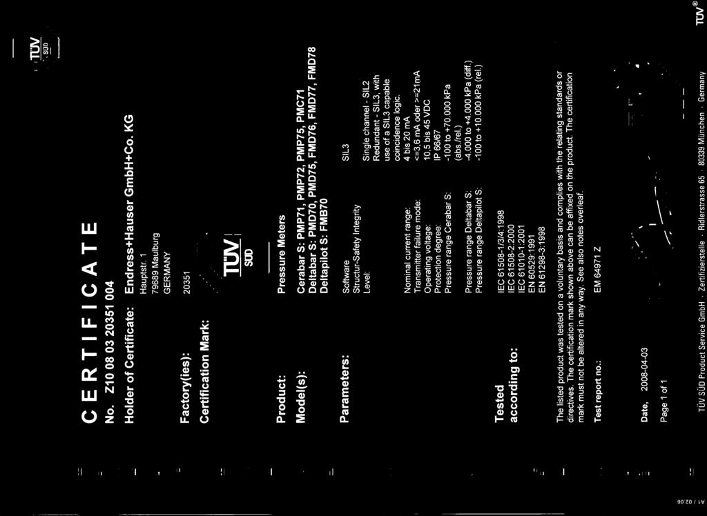
41 Certificate TUEV_en Endress+Hauser 41
Deltapilot S FMB70. Functional Safety Manual. Level and Pressure Measurement with Output Signal ma
 Functional Safety Manual Deltapilot S FMB70 Level and Pressure Measurement with Output Signal 4...20 ma Application Use for process pressure measurement in aggressive and non-aggressive gases, vapours
Liquiphant S, Nivotester FDL60/61, FTL670
 Functional Safety Manual Liquiphant S, Nivotester FDL60/61, FTL670 Level limit measuring system FTL670 s Application Overfill protection or maximum detection of all types of liquids, to meet the particular
Gammapilot M FMG60. Functional safety manual. Radiometric measurement technology Maximum point level detection
 Functional safety manual Gammapilot M FMG60 Radiometric measurement technology Maximum point level detection Application Overfill protection or maximum point level detection of all types of liquids and
Proservo NMS5- / NMS7-
 Functional Safety Manual Proservo NMS5- / NMS7- Tank gauge for Liquid level measurement with 4 to 20mA Output or with Alarm Relay Contact Output Application Operating minimum (e.g. dry run protection),
Functional Safety Manual Cerabar M PMC51, PMP51/55 Deltabar M PMD55 Deltapilot M FMB50/51/52/53
 SD00347P/00/EN/03.16 71344568 Products Solutions Services Functional Safety Manual Cerabar M PMC51, PMP51/55 Deltabar M PMD55 Deltapilot M FMB50/51/52/53 Process pressure / Differential pressure, Flow
Pressure Transmitter cerabar S PMC 731/631 cerabar S PMP 731/635 with ma output signal
 Safety Manual SD 159P/00/en Pressure Transmitter cerabar S PMC 731/631 cerabar S PMP 731/635 with 4...20 ma output signal Functional safety manual Application Pressure measurements (e.g. limit pressure
Pressure Transmitter cerabar M PMC 41/45 cerabar M PMP 41/45/46/48 with Output Signal ma/hart
 Safety Manual SD 172P/00/en 71036063 Pressure Transmitter cerabar M PMC 41/45 cerabar M PMP 41/45/46/48 with Output Signal 4...20 ma/hart Functional Safety Manual Application Pressure measurement (e.g.
Functional safety manual Liquiphant M/S with FEL57 and Nivotester FTL325P
 T T SD00231F/00/EN/14.14 71271294 Products Solutions Services Functional safety manual Liquiphant M/S with FEL57 and Nivotester FTL325P [Ex ia] [Ex ia] FTL325N FTL325N CH2 CH3 CH2 CH3 Level Limit Measuring
Differential Pressure Transmitter deltabar S PMD 230/235 deltabar S FMD 230/630/633 with ma output signal
 Safety Manual SD 158P/00/en Differential Pressure Transmitter deltabar S PMD 230/235 deltabar S FMD 230/630/633 with 4...20 ma output signal Functional safety manual Application Overspill protection or
ProcessMaster FEP300, FEP500 HygienicMaster FEH300, FEH500 Electromagnetic Flowmeter
 SIL-Safety Instructions SM/FEX300/FEX500/SIL-EN Rev. C ProcessMaster FEP300, FEP500 HygienicMaster FEH300, FEH500 Electromagnetic Flowmeter Information about functional safety Measurement made easy Change
Soliphant M with electronic insert FEM52
 Functional safety manual Soliphant M with electronic insert FEM52 Level Limit Measuring System Application Overfill protection or operating maximum detection of all types of solids in tanks to satisfy
SITRANS. Temperature transmitter Functional safety for SITRANS TW. Introduction. General safety instructions 2. Device-specific safety instructions
 Introduction 1 General safety instructions 2 SITRANS Temperature transmitter Device-specific safety instructions 3 Appendix List of Abbreviations/Acronyms A B Product Information Supplement to Operating
Operating Instructions Deltabar S FMD76/77/78, PMD70/75
 Operating Instructions Deltabar S FMD76/77/78, PMD70/75 Differential pressure transmitter 6 BA270P/00/en/05.04 52022793 valid from Software version 02.00 Hardware version 02.00 Overview documentation Deltabar
Certification Report of the ST3000 Pressure Transmitter
 Certification Report of the ST3000 Pressure Transmitter Revision No.: 1.0 Date: Report Number: Product: Customer: Order Number: Authority: Responsible: 2006-Dec-12 SAS-128/2006T ST3000 Pressure Transmitter
Functional Safety Manual Oil Leak Detector NAR300 System
 SD01357G/08/EN/01.14 71255416 Products Solutions Services Functional Safety Manual Oil Leak Detector NAR300 System Application This system is designed to be installed in a pit, dike, plant, or sump pit
Functional Safety Manual June pointek CLS500/LC500
 Functional Safety Manual June 2009 pointek CLS500/LC500 Introduction 1 Level Switch Pointek CLS500 SITRANS LC500 SIL Safety Manual Supplement to device manual General safety instructions 2 Device-specific
Introduction. Additional information. Additional instructions for IEC compliant devices. Measurement made easy
 ABB MEASUREMENT & ANALYTICS SIL-SAFETY MANUAL TTH300, TTF300 Temperature transmitter Additional instructions for IEC 61508 compliant devices Measurement made easy TTH300 TTF300 Introduction TTH300, TTF300
Certification Report of the ST 3000 Pressure Transmitter with HART 6
 Certification Report of the ST 3000 Pressure Transmitter with HART 6 Revision No.: 2.4 Date: Report Number: 2010-Mar-18 SAS-190/2006T Product: ST 3000 Pressure Transmitter with HART 6 Customer: Order Number:
Failure Modes, Effects and Diagnostic Analysis
 Failure Modes, Effects and Diagnostic Analysis Project: Detcon FP-700 Combustible Gas Sensor Customer: Detcon The Woodlands, TX USA Contract No.: DC 06/08-04 Report No.: DC 06/08-04 R001 Version V1, Revision
Safety in the process industry
 Products Solutions Services Safety in the process industry Simply reliable Table of contents Endress+Hauser: At home in the process safety Smart devices and concepts for hazardous areas Introduction to
United Electric Controls One Series Safety Transmitter Safety Manual
 United Electric Controls One Series Safety Transmitter Safety Manual OneST-SM-02 1 INTRODUCTION This Safety Manual provides information necessary to design, install, verify and maintain a Safety Instrumented
PPA Michaël GROSSI - FSCE PR electronics
 Functional Safety Component selection according to IEC61511 Title 2 Presentation Michaël GROSSI: Ex / SIL Product manager @ Degree in Instrumentation & Measurement More than 10 years experience in Functional
Meridian wiredhart. HART Field Device Specification Goldmine Rd. Monroe, NC USA
 HART Field Device Specification Meridian wiredhart 4320 Goldmine Rd. Monroe, NC 28110 USA HART is a registered trademark of the HART Communication Foundation TABLE OF CONTENTS 1. Introduction...5 1.1 Scope...5
SAFETY MANUAL. Electrochemical Gas Detector GT3000 Series Includes Transmitter (GTX) with H 2 S or O 2 Sensor Module (GTS)
 with H 2 S or O 2 Sensor Module (GTS)") SAFETY MANUAL Electrochemical Gas Detector GT3000 Series Includes Transmitter (GTX) with H 2 S or O 2 Sensor Module (GTS) Sensor Module (GTS) Transmitter (GTX) Detector (GT3000) SAFETY CERTIFIED GT3000
SAFETY MANUAL Electrochemical Gas Detector GT3000 Series Includes Transmitter (GTX) with H 2 S or O 2 Sensor Module (GTS) Sensor Module (GTS) Transmitter (GTX) Detector (GT3000) SAFETY CERTIFIED GT3000
Proof Testing Level Instruments
 Proof Testing Level Instruments Partial proof testing of level instruments can save millions of dollars while maintaining required safety ratings By Bill Sholette, Level Product Business Manager Endress+Hauser
SAFETY CERTIFIED MODEL FP-700 COMBUSTIBLE GAS DETECTOR
 SAFETY MANUAL SIL 2 Certified Model FP-700 Combustible Hydrocarbon Gas Sensor Version 2.0 1 SAFETY CERTIFIED MODEL FP-700 COMBUSTIBLE GAS DETECTOR This manual addresses the specific requirements and recommendations
SIPART. Electropneumatic positioner Functional safety for SIPART PS2. Introduction. General safety instructions 2. Device-specific safety instructions
 Introduction 1 General safety instructions 2 SIPART Electropneumatic positioner Device-specific safety instructions 3 Appendix List of Abbreviations/Acronyms A B Product Information Supplement to the manuals
SAFETY MANUAL. PointWatch Eclipse Infrared Hydrocarbon Gas Detector Safety Certified Model PIRECL
 SAFETY MANUAL PointWatch Eclipse Infrared Hydrocarbon Gas Detector SIL 2 Certified Model PIRECL Safety Certified Model PIRECL PointWatch Eclipse IR Gas Detector This manual addresses the specific requirements
Safety Temperature Limiter STL 50 Certified to DIN EN (replaces DIN 3440)
") Safety Temperature Limiter STL 50 Certified to DIN EN 14597 (replaces DIN 3440) Features M For use as: STB Protection - temperature limiter ASTB Exhaust gas - protection - temperature limiter STW Protection
Safety Temperature Limiter STL 50 Certified to DIN EN 14597 (replaces DIN 3440) Features M For use as: STB Protection - temperature limiter ASTB Exhaust gas - protection - temperature limiter STW Protection
STT850 and STT750 SmartLine Temperature Transmitter HART Communications Options Safety Manual 34-TT Revision 4 September 2017
 STT850 and STT750 SmartLine Temperature Transmitter HART Communications Options Safety Manual 34-TT-25-05 Revision 4 September 2017 Honeywell Process Solutions Copyrights, Notices and Trademarks Copyright
FUNCTIONAL SAFETY MANUAL
 FUNCTIONAL SAFETY MANUAL UltraSonic EX-5 Ultrasonic Gas Leak Detector The information and technical data disclosed in this document may be used and disseminated only for the purposes and to the extent
Guidelines. Safety Integrity Level - SIL - Valves and valve actuators. February Valves
 Valves Guidelines Safety Integrity Level - SIL - Valves and valve actuators February 2009 VDMA German Engineering Federation Valves Manufacturers Association Chairman: Prof.-Dr.-Ing. Heinfried Hoffmann
FMEDA and Proven-in-use Assessment. Pepperl+Fuchs GmbH Mannheim Germany
 FMEDA and Proven-in-use Assessment Project: Transmitter Supply Isolators KF**-CRG-*** Customer: Pepperl+Fuchs GmbH Mannheim Germany Contract No.: P+F 02/11-01 Report No.: P+F 02/11-01 R012 Version V2,
Failure Modes, Effects and Diagnostic Analysis
 Failure Modes, Effects and Diagnostic Analysis Project: ST3000 pressure transmitter Customer: Honeywell International Inc. Fort Washington, Pennsylvania USA Contract No.: HON 06/05-18 Report No.: HON 06/05-18
Failure Modes, Effects and Diagnostic Analysis. PR electronics A/S Rønde Denmark
 Failure Modes, Effects and Diagnostic Analysis Project: 9203 Solenoid / Alarm Driver Customer: PR electronics A/S Rønde Denmark Contract No.: PR electronics 06/03-19 Report No.: PR electronics 06/03-19
HAWK Measurement Systems Pty. Ltd. Centurion CGR Series Safety Manual
 HAWK Measurement Systems Pty. Ltd. Centurion CGR Series Safety Manual Document No. SIL0008 Version 1.7 17/04/2018 1. Revision History: Revision Author Reviewed Approved Update Details Date 0.1 Klaus Lorentschitsch
User s Manual. YTA110, YTA310, YTA320, and YTA710 Temperature Transmitters. Manual Change No
 User s Manual YTA110, YTA310, YTA320, and YTA710 Temperature Transmitters Manual Change No. 16-045 Please use this manual change for the manuals listed below. 1. Applicable manuals, revised item, revised
Failure Modes, Effects and Diagnostic Analysis. Rosemount Inc. Chanhassen, Minnesota USA
 Failure Modes, Effects and Diagnostic Analysis Project: 2088 Pressure Transmitter Customer: Rosemount Inc. Chanhassen, Minnesota USA Contract No.: ROS 06/10-18 Report No.: ROS 06/10-18 R001 Version V1,
Simply reliable: Process safety from Endress+Hauser
 Products Solutions Services Simply reliable: Process safety from Endress+Hauser Safety by choice, not by chance: Functional Safety Slide 1 Oil & Gas industry Hai-Thuy Industry Manager Oil & Gas Slide 2
GMA 301. Operation Manual. Worldwide Supplier of Safety Solutions. Part Number
 Worldwide Supplier of Safety Solutions GfG Instrumentation 1194 Oak Valley Drive #20 Phone: 734-769-0573 Fax: 734-769-1888 E-Mail: info@gfg-inc.com Internet: www.gfg-inc.com GMA 301 Operation Manual Part
FUNCTIONAL SAFETY MANUAL
 f u n c t i o n a l S a f e t y M a n u a l FUNCTIONAL SAFETY MANUAL Gassonic Surveyor and Gassonic Observer Ultrasonic Gas Leak Detectors The information and technical data disclosed in this document
FMEDA Report. Failure Modes, Effects and Diagnostic Analysis. KFD0-CS-Ex*.54* and KFD0-CS-Ex*.56* Project: X7300
 Failure Modes, Effects and Diagnostic Analysis Device Designation: KFD0-CS-Ex*.54* and KFD0-CS-Ex*.56* Project: X7300 Pepperl+Fuchs GmbH Mannheim Germany Mannheim norm sheet 1 of 16 Released EDM checkout
FUNCTIONAL SAFETY MANUAL. Gassonic Observer-H and Observer-i Ultrasonic Gas Leak Detector
 FUNCTIONAL SAFETY MANUAL Gassonic Observer-H and Observer-i Ultrasonic Gas Leak Detector The information and technical data disclosed in this document may be used and disseminated only for the purposes
RPM1600 Series Room Pressure Monitors
 RPM1600 Series Room Pressure Monitors Technical Bulletin LB-RPM1611-0, LB--0 Code No. LIT-12012228 Issued October 2017 Refer to the QuickLIT website for the most up-to-date version of this document. How
Rosemount Functional Safety Manual. Manual Supplement , Rev AF March 2015
 Rosemount 2120 Functional Safety Manual Manual Supplement Manual Supplement Contents Contents 1Section 1: Introduction 1.1 Scope and purpose of the safety manual.................................. 1 1.2
Failure Modes, Effects and Diagnostic Analysis
 Failure Modes, Effects and Diagnostic Analysis Project: 3144P SIS Temperature Transmitter Customer: Rosemount Inc. Chanhassen, MN USA Contract No.: ROS 04/08-19 Report No.: ROS 04/08-19 R003 Version V2,
Failure Modes, Effects and Diagnostic Analysis. Rosemount Inc. Chanhassen, MN USA
 Failure Modes, Effects and Diagnostic Analysis Project: 3144P SIS Temperature Transmitter Customer: Rosemount Inc. Chanhassen, MN USA Contract No.: ROS 04/08-19 Report No.: ROS 04/08-19 R003 Version V1,
Addendum HART Communication with the X2200 UV Flame Detector 1.1 4/
 Addendum HART Communication with the X2200 UV Flame Detector 1.1 4/09 Table Of Contents Interconnecting the HART Communicator with the Detector.... 1 HART Device Description Language.... 3 Detector Wiring.......................................
SAFETY MANUAL. Intelligent Sensors for H 2 S Gas Applications
 SAFETY MANUAL Intelligent Sensors for H 2 S Gas Applications The information and technical data disclosed in this document may be used and disseminated only for the purposes and to the extent specifically
SCAN200E USER S MANUAL
 SCAN200E USER S MANUAL Code No. 2071 1052 rev. 1.4 Code No. 2071 1052 Rev. 1.4 Page 2/16 SCAN200E User s Manual Foreword This manual is for SCAN200E Controller running software version 2.03 or later. We
Failure Modes, Effects and Diagnostic Analysis
 Failure Modes, Effects and Diagnostic Analysis Project: Oldham OLCT 200 Transmitter Company: Industrial Scientific Corporation Oakdale, PA USA Contract Number: Q11/05-009 Report No.: IS 10/10-010 R001
FUNCTIONAL SAFETY OF ELECTRICAL INSTALLATIONS IN INDUSTRIAL PLANTS BY OTTO WALCH
 FUNCTIONAL SAFETY OF ELECTRICAL INSTALLATIONS IN INDUSTRIAL PLANTS BY OTTO WALCH Troublefree and safe operation of industrial systems is of great importance, not only for the safety of the systems and
Safety Integrity Verification and Validation of a High Integrity Pressure Protection System to IEC 61511
 TÜV Rheinland International Symposium in China Functional Safety in Industrial Applications October 18 19, 2011 in Shanghai China Safety Integrity Verification and Validation of a High Integrity Pressure
Safety Manual. XNXTM Universal Transmitter. Fault Diagnostic Time Interval Proof Test Proof Testing Procedure
 XNXTM Universal Transmitter Safety Manual Table of Contents SIL 2 Certificates Overview Safety Parameters Fault Diagnostic Time Interval Proof Test Proof Testing Procedure Revision 2 Table of Contents
DOCUMENTATION IPS640
 DOCUMENTATION IPS640 TECHNICAL AND APPLICATION DESCRIPTION Authors: Nebojša Božič, Peter Hauner Last modification: 2018-07-06 2001-2018 Apricum d.o.o. Mažuranićeva 4, 21312 Podstrana, Hrvatska Details,
Failure Modes, Effects and Diagnostic Analysis
 Failure Modes, Effects and Diagnostic Analysis Project: Fireye Flame Sensor Module CE Flameswitch, model MBCE-110/230FR Company: Fireye Derry, NH USA Contract Number: Q09/10-26 Report No.: FIR 09/10-26
M-Sens 2. Online-Moisture Meter for Solids. Operating Instructions. SWR engineering Messtechnik GmbH
 EN M-Sens 2 Operating Instructions Online-Moisture Meter for Solids SWR engineering Messtechnik GmbH CONTENTS Page 1. System Overview......................................................................
Rosemount 2140:SIS Level Detector
 Rosemount 2140:SIS Level Detector Functional Safety Manual Manual Supplement Manual Supplement Contents Contents 1Section 1: Introduction 1.1 Scope and purpose of the safety manual..................................
SLG 700 SmartLine Level Transmitters Guided Wave Radar Safety Manual 34-SL Revision 4.0 December 2017
 SLG 700 SmartLine Level Transmitters Guided Wave Radar Safety Manual 34-SL-25-05 Revision 4.0 December 2017 Honeywell Process Solutions Copyrights, Notices and Trademarks Copyright 2017 by Honeywell, Inc.
SAFETY MANUAL. Multispectrum IR Flame Detector X3301
 SAFETY MANUAL Multispectrum IR Flame Detector X3301 SAFETY-CERTIFIED MODEL X3301 MULTISPECTRUM INFRARED DETECTOR This manual addresses the specific requirements and recommendations applicable to the proper
FlameGard 5 UV/IR HART
 FlameGard 5 UV/IR HART HART Communication Manual The information and technical data disclosed in this document may be used and disseminated only for the purposes and to the extent specifically authorized
DOCUMENTATION IPS640
 DOCUMENTATION IPS640 TECHNICAL AND APPLICATION DESCRIPTION Authors: Nebojša Božič, Peter Hauner Last modification: 2017-01-25 2001-2017 Apricum d.o.o. Mažuranićeva 4, 21312 Podstrana, Hrvatska Details,
FUNCTIONAL SAFETY: A PRACTICAL APPROACH FOR END-USERS AND SYSTEM INTEGRATORS
 FUNCTIONAL SAFETY: A PRACTICAL APPROACH FOR END-USERS AND SYSTEM INTEGRATORS TINO VANDE CAPELLE 1, Dr. MICHEL HOUTERMANS 2, 3 1- HIMA Paul Hildebrandt GmbH + Co KG, Brühl, GERMANY 2 Risknowlogy, Brunssum,
Smarter Field Instrumentation Life Cycle Management. Ray Rogowski Global Marketing PMC Instruments
 Smarter Field Instrumentation Life Cycle Management Ray Rogowski Global Marketing PMC Instruments Smart LifeCycle Management Pressure Temperature Radar Remote Seal Flange Mount User Interface Buttons Single
Addendum. HART Communication with the FlexSonic Acoustic Detector. 1.1 Rev: 1/
 Addendum HART Communication with the FlexSonic Acoustic Detector 1.1 Rev: 1/15 Table Of Contents Interconnecting the HART Communicator with the Acoustic Detector... 1 HART Device Description Language...
Failure Modes, Effects and Diagnostic Analysis
 Failure Modes, Effects and Diagnostic Analysis Project: 3144P 4-20mA HART Temperature Transmitter Device Label SW REV 1.1.X Customer: Rosemount Inc. (an Emerson Process Management company) Shakopee, MN
ICS Regent. Fire Detector Input Modules PD-6032 (T3419)
") ICS Regent Fire Detector Input Modules (T3419) Issue 1, March, 06 Fire detector input modules provide interfaces for 16 fire detector inputs such as smoke detectors, flame detectors, temperature detectors,
ICS Regent Fire Detector Input Modules (T3419) Issue 1, March, 06 Fire detector input modules provide interfaces for 16 fire detector inputs such as smoke detectors, flame detectors, temperature detectors,
Certificate: / 29 April 2014
 Test report: 936/21217455/A of 10 September 2013 Initial certification: 01 April 2014 Expiry date: 31 March 2019 Publication: BAnz AT 01 April 2014 B12, chapter I, No. 1.1 Approved application The tested
Failure Modes, Effects and Diagnostic Analysis
 Failure Modes, Effects and Diagnostic Analysis Project: Type 95IR/95UV/95DS Flame Scanners Customer: FIREYE Derry, New Hampshire USA Contract No.: FIR 04/08-21 Report No.: FIR 04/08-21 R002 Version V1,
Technical Manual for the Manual Alarm Call Point BG
 Technical Manual for the Manual Alarm Call Point BG Please note that every care has been taken to ensure the accuracy of our technical manual. We do not, however, accept responsibility for damage, loss
SIL Safety Guide Series MS Single-Acting Spring-Return Hydraulic Linear Actuators
 SIL Safety Guide Series MS Single-Acting Spring-Return Hydraulic Linear Actuators Rev 0, November 17 2015 Page 1 of 9 Table of Contents 1 INTRODUCTION 3 1.1 Terms and abbreviations 3 1.2 Acronyms 4 1.3
Manual Supplement. Model Number: 8680-N2. Communications Protocol. Contents of this manual supplement include:
 Model Number: 8680-N2 Product/System Title: Room Pressure AOC Controller with N2 Communications Protocol Contents of this manual supplement include: 1) Sequence of Operation 2) Variable map 3) Description
Thermal Mass Flowmeter Sensyflow FMT500-IG
 Pos: 1 /Titelblätter / Copyright/SIL/Durchfluss/SIL-Handbuch Sensyflow FMT500-iG Analog / HART @ 22\mod_1222423613156_3101.doc @ 218417 @ Pos: 2 /Titelblätter / Copyright/Copyright-Seite @ 32\mod_1247732119296_3101.doc
Technical Report Proven In Use SITRANS P500
 Technical Report Proven In Use SITRANS P500, Industry Sector, Industry Automation Division, Sensors and Communication, PD PA PI R&D PM CRT Oestliche Rheinbrueckenstr. 50 76187 Karlsruhe, Germany Number:
GMA200-MW4. User Manual. Gas detection controller for wall mounting
 User Manual GMA200-MW4 Gas detection controller for wall mounting GfG GESELLSCHAFT FÜR GERÄTEBAU MBH KLÖNNESTRASSE 99 44143 DORTMUND, GERMANY TEL. +49 / (0)231 / 564 00 0 FAX +49 / (0)231 / 516 313 INFO@GFG-MBH.COM
CELLTROL II BIOREACTOR CONTROL SYSTEM OPERATIONS MANUAL
 Operation Manual Celltrol II Bioreactor Control System Page 1 of 33 Table of Contents 1) Introduction... 3 1.1) Scope of Document... 3 1.2) Control System Overview... 3 1.3) Introduction to Celltrol II...
Safety Manual. XNX TM Universal Transmitter. Table of Contents SIL 2 Certificates Overview Safety Parameters
 XNX TM Universal Transmitter Safety Manual Table of Contents SIL 2 Certificates Overview Safety Parameters Fault Diagnostic Time Interval Proof Test Proof Testing Procedure Table of Contents 1 SIL 2 Certificate...3
100 & 120 Series Pressure and Temperature Switches Safety Manual
 100 & 120 Series Pressure and Temperature Switches Safety Manual MECH-SM-01 1 INTRODUCTION This Safety Manual provides information necessary to design, install, verify and maintain a Safety Instrumented
Operating Manual MS220DA
 ZIEHL industrie elektronik GmbH + Co KG Daimlerstraße 13, D 74523 Schwäbisch Hall + 49 791 504-0, info@ziehl.de, www.ziehl.de Temperature Relays and MINIKA Mains Monitoring Digital Panel Meters MINIPAN
KNX module for smoke alarm devices Dual/VdS and Q-Label (Order no )
") Product definition KNX module for smoke alarm devices Dual/VdS and Q-Label (Order no 2343 00) Art. no 2343 00 Page 1 of 22 Product definition Table of contents 1 Product definition... 3 1.1 Product catalogue...
Product definition KNX module for smoke alarm devices Dual/VdS and Q-Label (Order no 2343 00) Art. no 2343 00 Page 1 of 22 Product definition Table of contents 1 Product definition... 3 1.1 Product catalogue...
SAFETY MANUAL. IR5000 Open Path Hydrocarbon Gas Monitoring System
 SAFETY MANUAL Open Path Hydrocarbon Gas Monitoring System The information and technical data disclosed in this document may be used and disseminated only for the purposes and to the extent specifically
How E+H instrumentation can improve process safety
 Products Solutions Services How E+H instrumentation can improve process safety With special focus on Coriolis flowmeters Slide 1 Scope of presentation Slide 2 What is safety? Is this safety? Slide 3 Safety
Operating Guide Safe Torque Off
 ENGINEERING TOMORROW Operating Guide Safe Torque Off VLT Frequency Converters vlt-drives.danfoss.com Contents Operating Guide Contents 1 Introduction 2 1.1 Purpose of the Manual 2 1.2 Additional Resources
New Developments in the IEC61511 Edition 2
 New Developments in the IEC61511 Edition 2 Presented by Dr Issam Mukhtar PhD(Eng.) TÜV FS Expert (IDNo.:117/06) 6 th May 2013 2010 Invensys. All Rights Reserved. The names, logos, and taglines identifying
Engineering Guideline. pac-carriers Type for Yokogawa ProSafe-RS
 Engineering Guideline pac-carriers Type 9195 for Yokogawa ProSafe-RS 2 Engineering Guideline / Yokogawa ProSafe-RS 06.06.2017 Integrated solutions for Yokogawa R. STAHL offers a wide range of customized
SAFETY MANUAL. X2200 UV, X9800 IR, X5200 UVIR SIL 2 Certified Flame Detectors
 SAFETY MANUAL X2200 UV, X9800 IR, X5200 UVIR SIL 2 Certified Flame Detectors SAFETY-CERTIFIED Flame DETECTORs This manual addresses the specific requirements and recommendations applicable to the proper
RES-210 (-211, -220, -221) / RES-420
 / RES-420") RESISTR GB Replacing RES-2xx/ Replacement Instructions The RESISTR temperature controller can be used as an alternative to the following controllers of the series 200 : RES-210: Analog temperature display,
RESISTR GB Replacing RES-2xx/ Replacement Instructions The RESISTR temperature controller can be used as an alternative to the following controllers of the series 200 : RES-210: Analog temperature display,
ADOS Biogas 905. Multi-channel Gas Analyser. A D O S GmbH Instrumentation and Control Trierer Str FRG
 ADOS Biogas 905 Multi-channel Gas Analyser Issue: 05/2006 A D O S GmbH Instrumentation and Control Trierer Str. 23-25 @ 52078 Aachen @ FRG TEL. : (0241) 9769-0 FAX : (0241) 9769-16 E-Mail : info@ados.de
IEC61511 Standard Overview
 IEC61511 Standard Overview Andre Kneisel Instrumentation Engineer Chevron C.T. Refinery SAFA Symposium 2011 August 5 th, 2011 Presentation Overview Provide some understanding of the key aspects of Functional
Model D12-IR. Digital Gas Transmitter...
 Model D12-IR Digital Gas Transmitter... ATI s Series D12 gas transmitter line now includes a versatile Infrared system that can be configured for LEL or select toxic gases. The D12-IR utilizes a compact
M-Sens 2. Online moisture measurement for solids. Operating Instructions. SWR engineering Messtechnik GmbH PART OF THE ENVEA GROUP
 EN M-Sens 2 Operating Instructions Online moisture measurement for solids SWR engineering Messtechnik GmbH PART OF THE ENVEA GROUP CONTENTS Page 1. System overview.............................................
REGARD. REGARD 4-20 AND Ex CHANNEL CARDS INSTALLATION AND OPERATING MANUAL (FOR ATEX VERSION CARDS)
") REGARD REGARD 4-20 AND Ex CHANNEL CARDS INSTALLATION AND OPERATING MANUAL (FOR ATEX VERSION CARDS) Part No. 4206712 For use with Regard 4-20 and Ex cards software version 3.0 or later. Draeger Safety UK
REGARD REGARD 4-20 AND Ex CHANNEL CARDS INSTALLATION AND OPERATING MANUAL (FOR ATEX VERSION CARDS) Part No. 4206712 For use with Regard 4-20 and Ex cards software version 3.0 or later. Draeger Safety UK
FlameGard 5 MSIR HART
 FlameGard 5 MSIR HART Multi-Spectral Infrared Flame Detector HART Communication with the FlameGard 5 Multi-spectral Infrared Detector The information and technical data disclosed in this document may be
Functional Safety of Machinery Presented by Greg Richards Manufacturing in America 02/22-23/2017
 Functional Safety of Machinery Presented by Greg Richards Manufacturing in America 02/22-23/2017 AGENDA Definition of Safety? Machinery Safety Standards Comparison of ISO 13849-1 and IEC 62061 Safety-related
OMC Ex interface unit. Manual. Version 1.2 August Author: Observator Instruments
 OMC-158-2 Ex interface unit Manual Version 1.2 August 2017 Author: Observator Instruments Revisions: 0.1 (October 2016) First issue 0.2 (December 2016) Prototype 0.3 (January 2017) Test release 1.0 (March
Engineering Guideline. pac- Carriers Type Universal
 Engineering Guideline pac- Carriers Type 9195 Universal Integration of conventional process automation interfaces pac- Carrier The pac- Carrier reflects the intention of R. STAHL to provide state-of-the-art
Operating Instructions Edition 02/2007
 Operating Instructions Edition 02/2007 Temperature Transmitter 7NG3214 with PROFIBUS PA 7NG3215 with FOUNDATION Fieldbus sitrans Introduction 1 General safety notes 2 SITRANS T Temperature transmitter
Session Ten Achieving Compliance in Hardware Fault Tolerance
 Session Ten Achieving Compliance in Hardware Fault Tolerance Mirek Generowicz FS Senior Expert (TÜV Rheinland #183/12) Engineering Manager, I&E Systems Pty Ltd Abstract The functional safety standards
SIL2-Interface/ -Signal Conditioners Series DuoTec
 SIL2-Interface/ -Signal Conditioners Series DuoTec Certified according IEC 61508/ 61511 SIL2 DIN-Rail- and 19 -Mounting Since 1970 - Mütec Instruments GmbH Introduction To achieve a maximum safety in production
Automation, Software und Informationstechnologie
 Automation, Software und Informationstechnologie Report on the type approval of the Adjustable Frequency AC Drives PowerFlex 753 and 755 of Rockwell Automation Inc. Bericht-Nr.: 968/EZ 334.00/08 Datum: