Menntor X7 SERVICE MANUAL. Modular Patient Monitors FDM
|
|
|
- Chrystal Phillips
- 5 years ago
- Views:
Transcription


1 Menntor X7 Modular Patient Monitors SERVICE MANUAL FDM Rev.A Sept. 2014
2 Conformity according to the Council Directive 93/42/EEC concerning Medical Devices Manufacturer s Name : Mennen Medical Ltd. 4 Hayarden Street, Yavne, P.O. Box 102, Rehovot, , Israel Tel.: Fax: European Representative : Charter-Kontron Limited Unit 18 Avant Business Centre 21 Denbigh Road Milton Keynes MK1 1DT England Tel.: Fax: US Representative: Mennen Medical Corp. 290 Andrews Road Feasterville-Trevose, PA Phone Fax Publication No.FDM REV.A Revision: September 2014 Copyright Mennen Medical Ltd All RIGHTS RESERVED Registered trademarks are the intellectual property of their respective holders.
3 TABLE OF CONTENTS Chapter 1: System Description Overview Labeling Symbols Field Repairs Statement Training and Qualification System Features and Capabilities Monitor Inputs Controls and Outputs System Specification Chapter 2: Hardware Description Menntor X7 Overview Main Units CPU Card Main Storage Main Power Supply Power Supply Unit Rechargeable Battery Splitter Board Connectors: Main Units: Front Panel Rack Single Slot Board MX MX57 (MPM) Vital Signs ECG / RSP BP / CO Temp NIBP SPO2 (Nellcor) SPO2 (Masimo) EtCO2 Microstream, Plug-in Module Spirometry UIM - Universal Input Mennen Medical i
4 Menntor X7 Service Manual Remote Keypad (Optional) Chapter 3: Setting Up the System Introduction Accessing the System Setup Menu Date & Time Setup General Settings General Units Timeouts Hospital Name Setting the General Settings Panel Alarm Volume and Controls Enable Alarm Off Silence Time SpO2 Alarm Tone Priority Level Setting the Alarm Volume & Control Panel Sound Event Default Alarm Limits Event Setup Vital Sign (VS) Setup Accessing the Vital Signs Setup Dialog Panels ECG Setup Respiration Setup BP Setup NIBP Setup SpO2 Setup Temperature Setup CritiCool Setup EtCO2 Setup EtCO2 Calibration Cardiac Output (CO) Setup Transcoutaneous Gas (TcGas) Setup CO2 (from Anesthetic Gas) Setup O2 Setup N2O Setup Anesthetic Agent Setup Ventilator Setup Parameter Hierarchy Monitor Profiles Setup Showing/Hiding the Monitor profile on the Main Screen Changing the Position of an Monitor Profile Clearing a Monitor profile Admit by Default Report Setup Naming a Report Automatic Reports ii Mennen Medical
5 Menntor X7 Service Manual Network Setup Recorder Setup Trends Setup Quick Keys Setup Tabular Charts Naming a UDC Editing a UDC Clearing a UDC From the UDC List Updating the Software Version Enmove Interface Setup Change Password Check Disk Permission Editor Remove Saved Patients Touch Screen Calibration Demo Activation Copy Configuration Utility Chapter 4: System Installation Overview System Acceptance Safety Precautions Grounding the System Grounding Care Electrosurgery, Diathermy and Defibrillation Protection Mounting of Monitors Accidental Wetting of the Equipment General Hazards Site Survey Unpacking and Inspection Setting Up the Basic System Connecting and Wiring the LAN Cables Network Connections Mounting Options Mounting the Switch and Patch Panel Mounting and Connecting the LAN Hub and the Patch Panel Mounting the Menntor X7 Monitor on the Wall Chapter 5: Upgrading Software Upgrading Using Microsoft Windows Utilities General Required Hardware Required Software Upgrading Menntor X Copying the Tar file from the Laptop to Menntor X Upgrading Menntor X7 Software Mennen Medical iii
6 Menntor X7 Service Manual Chapter 6: Maintenance and Cleaning Periodic Testing and Preventive Maintenance Cleaning the Menntor X7 Bedside Monitor Replacing the Menntor X7 Battery Calibration and Preventive Maintenance Error Messages and Troubleshooting Error Messages Trouble Shooting Menntor X7 Bedside Monitor Troubleshooting Vital Signs Appendix A: Spare Parts Spare Parts Menntor X7.... A-1 Appendix B: Drawings External Connectors... B-2 Patient Input Connectors... B-3 Menntor X7 Assemblies... B-8 Menntor X7 - Top Assembly... B-8 Menntor X7 Mainframe Assembly... B-10 Menntor X7 BEZEL Assembly... B-12 Menntor X7 Rear Cover Assembly... B-14 Menntor X7 Bottom Assembly... B-16 Menntor X7 Rack Bottom Assembly... B-18 Menntor X7 Rack Assembly... B-20 MX57 Top Assembly... B-22 MX57 Main Board Assembly... B-24 MX57 Assemblies... B-26 MX57 Input Connections Assembly... B-26 MX57 Front Assembly... B-28 Spiro Module Assembly... B-30 EtCO2 Unit Assembly... B-32 Appendix C: Step-by-Step Assemblies Assembling MX57 Step-by-Step... C-1 Assembling Menntor X7 Step-by-Step... C-6 Appendix D: CerebraLogik Introduction... D-1 Indications for Use... D-1 Compliance... D-2 CerebraLogik Storage... D-2 Icons... D-2 Patient Safety... D-3 CerebraLogik Label... D-4 iv Mennen Medical
7 Menntor X7 Service Manual CerebraLogik - Waveforms and Display Modes... D-4 Quality Bar and Graph... D-5 CerebraLogik Full Disclosure... D-5 Operating Menntor X7 Monitor with CerebraLogik... D-5 Preparing for Operation... D-5 Electrode Location... D-6 Technical Alarm... D-7 CerebraLogik Service... D-7 CerebraLogik Drawing... D-7 Appendix E: Additional Information and Technical Assistance Appendix F: Laser Printer Setup Appendix G: Test Procedures Appendix H: Acceptance Report Mennen Medical v
8 Menntor X7 Service Manual vi Mennen Medical
9 CHAPTER 1: SYSTEM DESCRIPTION Overview Menntor X7 Patient monitoring system is a modular monitor that suits a wide range of patient applications. Menntor X7 offer solutions to both intermediate and critical care monitoring. It is mains or battery operated. It is offered with an optional touch screen for fast and easy operation. Menntor X7 is easily adapted to a diverse range of monitoring requirements including: Adult, Pediatric, Neonatal and patient transportation. Each monitor can be customized to meet the user's needs. As computerized monitors, Menntor X7 allows the user to take advantage of data connectivity, embedded data storage capabilities and high resolution display. Mennen Medical 1-1

 1-2")
10 System Description Menntor X7 Service Manual Labeling Figure 1-1: Menntor X7 Label Figure 1-2: Multi Parameter plug-in Module - MPM Label (1) 1-2 Mennen Medical
 Type BF applied part Type BF")
11 Menntor X7 Service Manual Symbols Figure 1-3: Multi Parameter plug-in Module - MPM Label (2) Following is a short description of the meaning of the various symbols which appear on the Menntor X7. Symbol Description Alternating Current Equipotential Danger High Voltage Attention, consult accompanying documents (Service to be performed by qualified technician) Type BF applied part Type BF applied par - Defibrillator-proof Type CF applied part - direct cardiac application defibrillator-proof Refer to instruction manual/ booklet Mennen Medical 1-3
12 System Description Menntor X7 Service Manual Symbol Description Restricts the sale and use of this instrument to qualified medical personnel only. Not for use in explosive gas environment Electrical and electronic equipment - Dispose according to local regulation Date of manufacture CE Mark 1-4 Mennen Medical
13 Menntor X7 Service Manual Field Repairs Statement Repair of Mennen Medical equipment in the field should be performed by service engineers, authorized by Mennen Medical. Repairs should be performed on a board level only. The list of replaceable component and boards is available in the spare part list. System testing should be performed using the test form available in the Service manual. Training and Qualification Mennen Medicalor it's authorized distributer provides training for technicians and sales personal as per the intended use of the device or system. The scope of the training is part of the agreement between Mennen Medical or it's authorized distributer and/or the end user. Servicing of Mennen Medical equipment is allowed only to persons trained and qualified to service the equipment efficiently and safely. System Features and Capabilities Menntor X7 displays a wide range of vital sign clinical parameters. It includes: ECG/Respiration multi-lead for monitoring ECG and respiration. Dual (four optional) BP inputs for monitoring two invasive blood pressures. CO/2TMP connector to measure either thermodilution Cardiac Output or two temperatures. Temp connector. NIBP input for monitoring non-invasive blood pressure using the oscillometric method. Pulse Oximetry. Microstream End Tidal CO2 (EtCO2) for monitoring CO2 during exhalation (EtCO2) and inhalation (inco2) and Respiration Rate. Serial Input for communication and interface with an external, auxiliary device. Menntor X7 s main monitoring features include: Continuously updated vital sign parameter data displayed as numeric values and continuous waveforms. Clinical and technical alarm detection as well as alarm notification in audio and visual formats. Easy access to collected data in the form of tabular charts and graphical trends as well as various types of clinical reports. Mennen Medical 1-5
14 System Description Menntor X7 Service Manual Patient data output to a recorder or a printer, if connected. You can interact with Menntor X7: Using interactive panels These panels include menus and dialog panels that enable you to configure system and monitoring parameters. Responding to Events Fixed keys on the front panel enable you to respond quickly to events such as alarms. Reviewing Clinical Data Charts, Trends, Full Disclosure and Overview enable you to view and compare data in different formats and over selected time periods. Monitor Display Features Inputs Menntor X7 can display up to eight traces, depending on how the vital sign display is configured. For monitor control procedures, refer to the User s Manual. All clinical data collected from the inputs is stored in the flash memory. This data includes waveforms, vital signs, trends, charts and beat-to-beat data. Menntor X7 can store at least 5 days of patient waveform and 80 days of numeric data for review purposes. The front panel of the main processing unit contains 5 fixed keys and the Quicknob. These features enable you to interact with the system. A remote keypad provides direct access, via the orange keys, to the menus of Vital signs, Patient data, and Setup, via the green keys, to Event, Print, Record, and Freeze and by the yellow key to Timer. This allows the user to reach these functions without opening the Main menu. For a detailed description of the functions and controls of the main processing unit, see Chapter 6 Controls and Functions of Menntor X7 User Manual. The main screen display is divided into four areas: Global Header Area Patient Area Patient Display Area QuicKeys For a description of all monitor display features and functions, Chapter 6 Controls and Functions of Menntor X7 User Manual. The Vital Signs inputs are housed on the left side panel. They include: 1-6 Mennen Medical
15 Menntor X7 Service Manual 12 Lead ECG/RSP Dual BP CO/2TMP Temp NIBP SpO2 EtCO2 MicroStream Controls and Outputs Video output for external display External keyboard and mouse Remote keypad Analog output EtCO2 gas outlet System Specification See the following pages. Mennen Medical 1-7

16 Menntor X7 Specification Menntor X7 is a modular monitor consisting of a Host Monitor a Multi Parameter Module, and two Single Parameters Modules. Menntor X7 Host Monitor Specification Hardware and Parameters Menntor X7 is a modular monitor with a built-in display and battery back-up. MX57 - Multi Parameters Module Non Invasive 3/5/12 lead ECG Respiration NIBP SpO2 (Nellcor ) 2 Temperatures Universal Input Module - UIM 2 x RS232 ports Interface to other vendor devices: Anestheic gases: Poet IQ, Andros 4800, Leon Plus, IRMA Ventilators: EVITA, Monet, Matisse, Saturn Evo, Stephanie Continuous CO: Vigilance, Vigileo, PiCCO2 Other: BISx, CritiCool, Micropod, Radical-7, CerebraLogik Display-Host Unit LCD (1024x768): 15 Waveform display horizontal area: 195 mm Numeric Display horizontal area: 95 mm vertical area: 23 mm Very Big Numbers One or Two Lead ECG WF HR height: 45 mm Four areas with Waveform height: 15 mm Numeric Vital Signs height: 35 mm Interface to a Remote Display Waveform Display - Standard 7 sec, grid 5 boxes/sec (25 mm/sec nominal) up to 8 traces and up to 14 traces (during 12 lead ECG) Overlapping Pressure Waveforms mode Sweep Speed: 6.25, 12.5, 25, 50, 100 mm/sec (nominal) Cardio Respiratory Graph (CRG) - up to 4 parameters Big Numbers Waveform + Trend Format: 2/3 waveforms and 1/3 graphic Trend Very Big Numbers mode Host CPU Details Via X 86 Core Fusion CPU Sound Blaster 2W audio power / 8Ω Mass storage: 8 GB / 16 GB Operating System: QNX 4.25 Window manager: Photon SW upgrades via network or memory card Dimensions\Weight Menntor X7 with MX57 MPM Module HxWxD: 361x392x215 mm (14.2x15.4x8.4 inches) Weight: 8.5Kg. (18.7 lb) (for basic configuration with battery) Power requirement VAC, 2A, 50/60 Hz VAC, 1A, 50 Hz Battery Single Battery Environmental Operating Conditions Temperature: +5 0 C to C (41 F to 104 F) Humidity: 10 to 93 percent, non-condensing Barometric Pressure: mmhg (-1250 to 15,000 ft. ; -380 to 5200 meter) Temperature: -15C O to +68C O (5 F to 154 F) Humidity: 10 to 93 percent, non-condensing Menntor X7 Dual Battery Lithium Ion 14.8V / 5.2A 14.8V / 10.4A Operation Time (Hours) 3 6 Charge Time (Hours) 3 6 Environmental Storage Conditions Invasive 3/5/12 lead ECG Respiration NIBP SpO2 (Nellcor ) 2 Temperatures/ 4 Temeratures 2 x IBP (optional 4 IBP available) CO / 2 additional Temperatures Network LAN Physical: IEEE Ethernet interface 10/100 BaseT Protocol: TCP/IP Serial Interface RS232 (optional) Connectivity to: Ensemble (CNS), Enguard, Enscribe (recorder) and network printer Wireless LAN (optional) includes: Utilizes an industry-standard b/g IEEE compliant radio card Dual-diversity dipole antenna Signal strength indicator WPA security and encryption User Controls- Host Unit 6 Fixed Keys Quicknob Remote Control Keypad (optional) Touch Screen ELO IT (optional) Barcode Reader (optional) Patient Data storage- Host Unit Demographic Data Charts - Numerical Trend - Graphic Full Disclosure - All leads ECG waveform Overview - All Waveforms with top ECG Event Strips 20 Seconds of all ECG and Vital signs waveforms (10 sec pre & post event) Calculations - Host Unit Medications Hemodynamics Respiratory Mechanics Oxigenation Renal Clearance Fick Cardiac Output Heart Rate Variability (HRV): Time Domain Histogram Default Alarms - Host Unit User defined Fixed or calculated values Alarm levels: Clinical levels: C1, C2, C3, C4 Technical levels: T1, T2. Visual and Audible alarm Output Alarms by Analog Switches Recorder (Optional) - Host Unit Integrated Recorder up to 3 channels Analog Output - Host Unit ECG II 1Volt/mV (pin1, 5 Gnd) ECG V1 1Volt/mV (pin2, 6 Gnd) QRS 5 Volt ART 1Volt/100 mmhg (pin4, 8 Gnd) Output to input delay < 20 msec Languages English, Dutch, Espanol, French, Greek, Italian, Polish, Portuguese, Russian, Spanish, Turkish. Regulatory Approvals EN EN EN Degree of protection against electrical shock ECG / RSP, IBP, CO and TEMP = Type CF NIBP, SpO2 and EtCO2 = Type BF CE Mark 0473 Pending FDA Clearance - K073140, K Pending WIFI FCC ID XM5-SM2144N1/2 Industrial Canada 8516A-SM2144N1/2 DGM Rev B 09/2014. Page 1/5
17 Menntor X7 Technical Specification MX57 - Multi Parameter Module The MPM, when disconnected from the host will serve as a stand alone transport monitor Monitor Profile and alarm setting are fixed, as received from the host Upon return to the host, the data collected during the transport will merge with the data collected by the host CPU Detail Arm Cortex A8 AC97 Sound Card - 2W audio power 8 ohm Mass storage: 2 GB Operating System: Linux and TI CCD Dimension / Weight HxWxD: 170 x 80 x 225 mm (6.7 x 3.0 x 8.8 inches) Weight: 1.4 Kg. (3.08 lb) Display (optional) LCD (640 x 480): 5.7 optional ECG. One Waveform display horizontal area: 82 mm HR height 20 mm Power - Battery operated Lithium Ion: 16.8 VDC / 2.6 A Operation Time: 5 (Hours) Charge Time: 4 (Hours) from host Environmental Operating Conditions Temperature: +5C to +40C (41 F to 104 F) Humidity: 10 to 93 percent, non-condensing User Controls 5 Fixed keys : Silence, Event Mark, IBP Zero, NIBP, On/Off Data Storage Storage time Demographic Data Numerical Vital Sign Full Disclosure - All leads ECG waveform Overview - All Waveforms with top ECG Event Strips (for each event) 20 Seconds of all ECG and Vital signs waveforms 10sec pre & post event) Alarms Alarm levels: Clinical levels: C1, C2, C3, C4 Technical levels: T1, T2. Visual and Audible alarm Battery Status Alarm Numeric Display 4 areas Big Numbers boxes horizontal area: 58 mm vertical area: 30 mm Vital Signs Waveform height: 11 mm Numeric Vital Signs height: 15 mm Sweep Speed: 6.25, 12.5, 25, 50, 100 mm/sec (nominal) Single parameter modules EtCO2 Spirometry Dimension / Weight HxWxD: 95 x 40 x 120 mm (3.7 x 1.6 x 4.7 inches) Weight: 0.3 Kg. (0.6 lb) MX57 - MPM Mounting (Optional) DGM Rev B 09/2014. Page 2/5
18 Menntor X7 Clinical Specification ECG (3 / 5 / 12 Lead) Leads: ECG cables for 3/5/12-lead surface ECG with defibrillation protection in the cable. Input Dynamic Range: ±5 mv peak to peak Input DC Offset: ±530 mv Baseline Correction: Automatic recovery of waveform within 100 msec Notch Filtering: 50Hz or 60Hz Frequency Response: Diagnostic 0.05 to 150Hz Monitoring 0.5 to 40Hz ST 0.05 to 40Hz Exercise 1 to 25Hz Sensitivity: 0.25, 0.5, 1.0, 2.0, 4.0, 8.0 mv/cm (nominal) Common Mode Rejection: 120 db minimum Noise: 30 µv Input Impedance: 2.5 megaω Defibrillator Pulse Protection: Yes Baseline Recovery: < 8 sec Lead Fault Sense: Based on impedance with driven lead: Sense current < 90 na, DC Digital Sample Rate: 640Hz Sample Resolution: 24 bit Pacemaker Detection and Rejection of Pacer Artifact. Amplitude: +/- 2 mv to +/- 700 mv Width: 0.1 ms to 2.0 ms Pacer Detection Flag inserted into ECG waveform. 3 Detection Modes: 1. Fixed Threshold 2mV 2. Adaptive 1 Threshold ½mV High Sensitivity 3. Adaptive 2 Threshold > 2mV High Immunity Auto Cable Detection Audio Indicator: QRS Beep Adjustable volume QRS Detection Range: Height: 0.25 or 0.15 mv to 5.0 millivolt Width: 70 to 120 milliseconds Heart Rate Counting: Range: 0 to 350 BPM Accuracy: ±2 BPM, Accuracy ±4 BPM Heart Rate averaging: 3/4 of last average + 1/4 new beat (about 8 beats between 60 to 120, or 120 to 60) Note: Values below 20- forced to zero Heart Rate Alarm Settings High and low rate: BPM non-overlapping Leads analyzed for Heart Rate and Arrhythmia Configuration: Top two displayed ECG Leads: I, II, III (3 Lead cable) I, II, III, avr, avl, avf, V (5 Lead cable) I, II, III, avr, avl, avf, V1-V6 (12 Lead cable) ST on all leads: Automatic or Manual ST range + 8 mm to 8 mm ST Alarm Arrhythmia: Detection and alarm on 19 Arrhythmias PR and QT measurement and display Data Storage:Beat notification, RR Interval, Heart Rate, ST values, Arrhythmia, Alarms, Alarm event markers Respiration Leads: RA-LA or Leads: RA-LL Excitation: 65 khz Sinus wave, < 1 ma Input Impedance: >40 KΏ Frequency Response: 0.13 to 2.5Hz Impedance Range: 100 to 3000 Ω Input Sensitivity Range: 0.2 to 5 Ω Digital Sample Rate: 640 Hz Sample Resolution: 24 bit Sweep Speed: ECG speed, 6.25, 12.5 mm/sec (nominal) Gain: Automatic or 1/8 to x 8 Respiration Rate Counting Range: 0 to 150 breaths/min Respiration rate: Accuracy +/- 1 per minute Respiration Alarm Settings Low rate: BPM High rate: BPM Apnea: User configurable (10, 15, 20, 30, 45, 60, 90 Sec.) Cardiac coincidence alarm Modes: Normal / Cardiac Data Storage: Respiration rate, Respiration rate Alarms, Apnea alarms Alarm event markers DGM Rev B 09/2014. Page 3/5 Invasive Blood Pressure Site Labels: BPx, ART, PAP, CVP, RAP, LAP, ICP Input Sensitivity: 5 µvolt/volt/mmhg IBP waveform synchronized to ECG Dynamic Range Pressure range: -50 to +350 mmhg Zero range: ±150 mmhg Total dynamic range: -200 to +450 mmhg Heart rate: BPM Transducer Excitation Voltage: +5 VDC Separate excitation driver for each channel Zero Accuracy: ±0.2 mmhg Zero Drift: Less than ±0.2 mmhg in 24 hours, (at constant temperature) Blood Pressure Accuracy: ±2 mmhg or ±2%, whichever is greater, exclusive of transducer Blood Pressure Linearity: within 1% across entire range Waveform Frequency Response: 0-40 Hz Sampling Rate: 640 Hz Sample Resolution: 24 bit Fault Detection; Transducer in/out, Cable out Data Storage:Systolic, Diastolic and Mean; Alarms Pulse Oximetry (Sp02) Nellcor Oximax Plethysmograph waveform Saturation Range: 0% to 100% Sp02 Extreme Alarm Capability Sp02 Accuracy: SpO2 % +/-3 digits standard deviation Pulse Rate Range: 20 to 250 BPM +/-3 BPM Saturation alarm limits: 0% to 100% Data Storage:Heart rate and O2 saturation, Alarms Thermo Dilution Cardiac Output Adapter and Compatibility Cables: CO Set interface cable Ice Bath YSI-400 cardiac output interface cable Dual temperature interface cable (YSI-400) Temperature Range Blood temperature: 27 0 C to 45 0 C (81 0 F to F) Injectate temperature: 0 0 C to 25 0 C (32 0 F to 77 0 F) Body temperature: 0 0 C to 45 0 C (32 0 F to F) Accuracy ±0.1 O C over the entire range Digital Sample Rate: 160 Hz Sample Resolution: 24 bit Frequency Response: 0 to 15 Hz Cardiac Output Determination Range: 0 to 20 liters per minute Injectate Volumes: 1, 3, 5, and 10cc Displayed Data: Cardiac Output, Cardiac Index, Stroke Volume, Stroke Volume Index, Blood Temperature, Injectate Temperature, Trial Number Data Storage: In Cardiac Output mode: Cardiac Output, Hemodynamic Calculation results Measuring time In Two Temp mode: Temperatures and Delta-Temp, Temperature Alarms Non-Invasive Blood Pressure Oscillometric Method Displayed Parameters: Systolic, Diastolic, Mean pressure values, Time of last measurement, and next measurement Cuff Size: Adult, Pediatric, Infant, Neonatal Inflation Rate: Within 5 sec. Initial inflation target: 150 mmhg, Adult/Pediatric Initial inflation target: 100 mmhg, Neonatal Over pressure limit : 290 mmhg, Adult/Pediatric Over pressure limit : 145 mmhg, Neonatal Cycle Times Deflation time (typical): 30 sec.; BP time-out: sec. Measurement Ranges, Adult (in mmhg) Systolic: 30 to 255; Diastolic: 15 to 220; Mean: 20 to 235 Measurement Ranges, Neonatal (in mmhg) Systolic: 30 to 135; Diastolic: 15 to 110; Mean: Pressure: Transducer Accuracy ±3 mmhg or ±2%, whichever is greater Heart Rate: Adult/Pediatric: 30 to 240 BPM Neonatal: 40 to 240 BPM Modes: Auto, Manual, STAT Automatic intervals 1,2,3,4,5,10,15,20,30,60,120,180,240,360, 480 minutes Data Storage: Measurement time markers, S/D/M, Alarm event markers We follow every beat of your heart Mennen Medical Ltd. All rights reserved. Specification subject to be changed without notice.
19 Temperature YSI 400 Series Probes Body temperature: 0 0 C to 45 0 C (32 0 F to F) +/ C Temperature Alarm Range: 25 0 C to 45 0 C (77 0 F to F) Data storage: Temperature and Delta temperature, Temperature alarms Delta Temperature Range + / C Delta temp Accuracy: +/ C End Tidal CO2 Microstream (EtCO2) Module Sidestream method Flow rate: 50 ml/min (accuracy: -7.5ml/min + 15ml/min ) Displayed Data: Waveform labels and annotations EtCO2, in CO2 and respiration rate values CO2 Display Range: 0-99 mmhg Measurement Resolution: Typical Accuracy ±2 mmhg for CO2 range of 0-38 mmhg +0.08% for every 1 mmhg above 38 mmhg ±5% for CO2 range of mmhg Respiration Rate: 0 to 70 bpm: ±1 bpm 71 to 120 bpm: ±2 bpm 121 to 150 bpm: ±3 bpm Rise Time: 190 msec (10% - 90%) Delay Time: 2.7 Sec (10% - 90%) typical Start-up Time: 30 sec typical Automatic Compensation: At least once per hour Ambient Temperature: 0-65 C, Humidity: 10-95%, non-condensing Barometric Pressure: mmhg (-1250 to 15,000 ft. ; -380 to 5200 meter) Calibration required: Initially after 1200 operating hours and then once a year or 4000 operating hours CO2 Alarm Limits: 0 to 100 mmhg; 0 to 10%; 0 to 15 kpa Respiration Rate Alarm Limits: Neonatal - 0 to 150 BMP; Adult - 0 to 50 BPM Data Storage:EtCO2, inco2 and Respiration Rate values, Alarms, Apnea Alarm Exhaust Gas Outlet BIS Interface BISx Technology Bispectral Index (BIS): 0 to 100 (0 = no brain activity, 100 = fully conscious) Electromyographic Strength (EMG): 25 to 100 db (where 1µV = 40dB) Signal Quality Index (SQI): 0 to 100% Suppression Ratio (SR): 0 to 100% Spectral Edge Frequency (SEF): 0.5 to 30.0 Hz Total Power (TP): 40 to 100 db (1µV2 RMS = 40dB) Burst Count (BC): 0 to 30 (with an Extend Sensor only) EEG: Two channel, real-time EEG waveform Noise (EEG Waveform) < 0.3 µv RMS (2.0µV peak-to-peak) BIS Numeric Update Frequency: Once per second Band width: 0.25 to 100 Hz (- 3dB) Filters: High Pass: 0.25, 1, 2 Hz Low Pass: 30, 50, 70 Hz Notch: 50 or 60 Hz Impedance Measurement Range: 0 to 999 kohm Data Storage: Numeric Chart Graphic Trend and EEG waveform full disclosure CRG trend Display features: EEG waveforms EEG waveform + Trend of BIS and EMG BIS value and alarm limit EMG and SQI at vertical bars SR, BC, TP numeric display Alarms: High BIS alarm: Low BIS alarm: DGM Rev B 09/2014. Page 4/5 Anesthetic Gases Module Agent Gas External Module using Poet IQ bench technology with Automatic 5 Agent Identification. Size: (WxDxH) 264 x 208 x 96 mm / 10.4 x 8.2 x 3.8 in. Weight 3.4 kg / 7.5 lbs. Power: Input Voltage 100 to 240 Vac - 48 to 62 Hz Sampling Gas Flow Rate: 100 ml/min. Environment: Temperature: +15 to +35 C / +59 to 95 F Humidity: 15 to 95% RH (non-condensing) Barometric Pressure / Altitude: 525mmHg to 790mmHg -300m to + 3,000m (-1,000 ft 10,000 ft) Gas Specifications CO2 Gas Range Accuracy (1-30 BPM) 0.0 to 30mmHg ± 1.5mmHg 30.1 to 76mmHg 5% Relative O2 - fast 0.0 to 100.0% ±2.5% abs. plus 2.5% rel. Breath Rate 0 to 100bpm ± 2bpm N2O 0.0 to 100% ± 1.5% abs. plus 5% rel. Isoflurene 0.00 to 7.5% ± 0.1% abs. plus 4% rel Halothane 0.00 to 7.5% ± 0.1% abs. plus 4% rel Enflurane 0.00 to 7.5% ± 0.1% abs. plus 4% rel Sevoflurane 0.00 to 9% ± 0.1% abs. plus 4% rel Desflurane 0.00 to 20% ± 0.1% abs. plus 4% rel. MAC Spirometry Module LED for function indication For use for patients with tidal volumes greater than 100 ml. Waveforms: Air Flow Air Volume Airway Pressure Loops: Flow Volume Pressure Volume Flow Pressure Spirometry Measured Parameters RR - Respiration Rate VT - Tidal Volume MV - Minute Volume PIP - Peak Inspiration Pressure MAP - Mean Airway Pressure PEEP - Positive End Expiratory Pressure RES - Resistance COMP - Compliance PLTP - Plateau Pressure Menntor X7 Clinical Specification Calculated from N2O + Agent EZ-Flow TM Flow Airway Adapter Specifications Flow Range: lpm ( ml/s) Accuracy: ±5% reading, or 0.5 lpm Dead Space: 6.9 ml Flow (L/min): Range: Adult 2.0 to 180 Accuracy: Greater of 0.5 LPM or ±3% of reading Tidal Volume (ml) Range: Adult 200 to 3000 Resolution: Adult 1 ml Volume Accuracy: Greater of ±10 ml or ±3% of reading Respiration Rate (breaths/min) Range: Adult 2 to 120 Accuracy: Adult ±1 Airway Pressure (cm H2O) Range: Adult -120 to 120 Resolution: Adult 0.1 cm H2O Accuracy: Adult ±2% of reading We follow every beat of your heart Mennen Medical Ltd. All rights reserved. Specification subject to be changed without notice.

20 CerebraLogik Specification The CerebraLogik is a dual channel EEG amplifier, with Amplitude Integrated EEG (aeeg) recording and display capability. It is used as a front end EEG amplifier interfaced to Menntor X7 Monitors, where EEG and aeeg can be displayed and stored, simultaneously with all patient vital signs monitored on the Menntor X7. CerebraLogik Module CerebraLogik interface to Menntor X7 with Monitor mass storage: 16GB Physical HxWxD: 140/95/30 mm (5.5/3.7/1.2 inch) Weight: 385gr (0.849 lb) (with mounting clip and cable) Interface Cable length: 1.2meter (47.2 inch) 5 sockets for DIN safety electrodes cables Power Consumption: 5V/300 ma Mounting Clip Amplifier 2 different amplifiers: Left, Right + Reference. Input Range +/- 5.0 mv p-p full scale Input impedance > 5 MΩ Linearity ±2% DC input offset: +/ mv maximum Common Mode Rejection Ratio 130 db at 50/60 Hz Frequency Response 0.5 Hz to 75 Hz (-3db) Noise < 10nV/ sqrt(hz) at 100Hz Bias Current: Less than 7nA per input Input isolation Double isolation A/D Sampling rate: 640 Hz per channel A/D span: 24 bits Low filter (High pass) 0.5/1.5 Hz High filter (Low pass) 15/35/50/70 Hz Degree of protection: Type BF Applied part aeeg Monitoring Parameters 2 x Differential channel (Left, Right): EEG/aEEG channels 1 Cross Channels ("Left Right") : EEG/aEEG Signal Quality (Resistance) - 0 to 5 (Arbitrary units) EEG Gain: 10,20,50,70,100,200 µv/cm; aeeg Range: 100, 200µV EEG/aEEG history duration: Up to 7 days recording aeeg panel : 3 Hour Display EEG sweep speed : 15 or 30 mm/sec Section marking Event marking Built-in Recorder (Optional) Data Export Data printing on recorder (Optional) USB for Data output (viewer on PC) Environmental Operating Conditions Temperature: +5 0 C to C (41 F to 104 F) Humidity: 10 to 93 percent, non-condensing Environmental Storage Conditions Temperature: -15C O to +68C O (5 F to 154 F) Humidity: 10 to 93 percent, non-condensing Regulatory Degree of protection: Type BF Applied part EN EN (EMC) (EEG) CE Mark 0473 DGM Rev B 09/2014. Page 5/5
21 CHAPTER 2: HARDWARE DESCRIPTION This chapter includes the following sections: Menntor X7 Overview CPU Card Main Storage Main Power Supply Rechargeable Battery Power Splitter Board Front Panel Rack Board Single Slot Board MX 57 - Multi Parameter Module (MPM) WARNING!!! Electrical shock hazard! Disconnect the main A/C power supply cable from the A/C power socket before service!! If power must remain connected for troubleshooting while the unit is uncovered, use extreme caution. When you have completed a test, immediately unplug the unit. Do not wear rings,bracelets or metal objects that may come in contact with live power contacts. Mennen Medical 2-1
22 Hardware Description Menntor X7 Service Manual Menntor X7 Overview The following electronic block diagram describes the main units and internal interfaces for the Menntor X7 system. Touch VitaLogik 7000BD Power & Com LCD" 15 LVDS LCD Inverter WIFI Com() 4 Speaker VGA CF VitaLogik SBC Com & LPT LAN PS2 Ram128- MB 5V Pwr LAN Rack Pwr State UIM Aux SPB User Interface Recorder FAN UIM & Aux Module x2 MPM Power Supply Battery Main AC Line Filter Remote Figure 2-1: Electronics block diagram of main units and internal interfaces of Menntor X7 Main Units Menntor X7 Main CPU (see CPU Card ) MX57 Front End ( see MPM ) Power Splitter ( see Rechargable Battery ). User Interface ( see Front Panel ) Recorder: Optional built-in recorder for 25mm/Sec 3 WF printing. L-ion battery: 16.8Volt 5.2A L-ion battery. Medical Power Supply:"XP" medical grade power supply for output voltage of 24Volt/100W AC Line filter: AC line filter with dual fuses for medical uses. 2-2 Mennen Medical

23 Menntor X7 Service Manual LCD: Integrated NEC 15" / SHARP 15" XGA display with LVDS interface. Inverter:The inverter provides high voltage for the NEC LCD and low voltage for Sharp LCD. The light level is controlled by the power splitter board via an analog signal. Note:SHARP display does not require an inverter. Touch Screen : ElO 15" IT which communicates with the CPU via a serial interface with 5 volt power signal from CPU. Main Storage: Flash memory card (see Main Storage ). Figure 2-2: Menntor X7 Internal Wiring Diagram Mennen Medical 2-3
24 Hardware Description Menntor X7 Service Manual CPU Card Main Storage The main CPU board is a unique single board computer, custom designed. Intel Atom N GHz Processor Onboard, FSB 533 MHz, TDP=2.5W Intel 945GSE + ICH7M Chipset Onboard DDR2-400/ MB Memory Integrated Graphic Media Accelerator GMA950, VGA Support Gigabit Enternet x 2 (Intel 82574L) HD Audio Codec with Realtek ALC655, with 2 channel Each 2 Watts SP-ou CompactFlash Type II x 1 USB2.0 x 3, RS-232/422/485 x 1, RS-232 x 3, Parallel x 1 Extensive 36-bit LVCS LCD Support Mini-PCI Slot, and Put Mini-PCI Slot On The Bottom Side On-board sound blaster and audio amplifier BIOS Setup configured for Mennen Medical Ltd. applications. The CPU runs the Mennen Medical Ltd.Patient Monitoring application under QNX4.25 operating system which is located on the external flash card. The main storage consists of a 8 GB or 16 GB flash memory which stores the QNX operation system with PHOTON window manager and the Menntor X7 system application software. The flash memory stores all of a patient s clinical data (vital signs and waveforms). These files are retrieved when the user enters the data review panels. 2-4 Mennen Medical

25 Menntor X7 Service Manual Figure 2-3: Flash Card Size Main Power Supply The main power supply is composed of a power supply module (AC to DC), DCto-DC Splitter board, and a rechargable battery. Power Supply Unit "XP" medical grade power supply for output voltage of 24Volt/100W. The main power supply supplies DC voltage to the Splitter board. Note:There is no field adjustment or repair. In case of malfunction, replace with a new power supply supplied by Mennen Medical Ltd. Rechargeable Battery The unit is supplied with single 16.8Volt 5.2A L-ion battery (two batteries are optional). The unit can operate for 3 hours with single battery and 6 hours with two batteries. Splitter Board The AC input voltage is VAC. The Splitter Board handles the followings: DC/DC Converter; Input: +24V Output:+12V, +8.25V, +5V Batteries charger and switching between AC to DC. Mennen Medical 2-5
 and LPT interface connector Aux Interface UIM x 2 Interfaces Rack Interface Auto shutdown feature at low battery Connectors: Figure 2-4: Power Splitter Board.")
26 Hardware Description Menntor X7 Service Manual Panel; power and User Interface Remote control; power and user interface LCD; power and light level Touch screen; Power and control Recorder; power (8.25V) and LPT interface connector Aux Interface UIM x 2 Interfaces Rack Interface Auto shutdown feature at low battery Connectors: Figure 2-4: Power Splitter Board. PN Rack: Interface connector provides the followings: Power lines of 5V, Volt for MX57, Rack board and single slots modules. UIM x 2 serial interface Analog output signals Host monitor state signal MX57 present signal from rack to SPB. 2-6 Mennen Medical
27 Menntor X7 Service Manual CPU : (Menntor X7 Main board) the power connector provides +5Volt for Menntor X7 main board via U2 switch regulator (item 2 in Figure 2-4). The power circuit is controlled by main controller which turns On/Off the power according to the monitor state. Maximum quiescent current is ~3500mA. COM1: S232 UART interface between power splitter board and Menntor X7 main board. All user interface commands are transmitted to/from the Menntor X7 CPU via this interface. LPT: Parallel interface to Menntor X7 main board. This interface is using for built in recorder option. COM2: RS232 UART interface between touch screen controllers, to Menntor X7 main board. Recorder Connector: Parallel interface to built-in recorder. This interface includes dedicated 8.25Volt power circuits (item 3 in Figure 2-4). Panel Connector: Interface connection to front panel board. LCD Connector: Interface connector to LCD inverter. This interface includes dedicated 12Volt power circuits (item 6 in Figure 2-4) which controlled by the main controller. The interface includes control line for back light power consumption which can control the light value for AC connection and battery use. Touch Screen: RS232 UART interface between touch screen controller to Menntor X7 main board. The power splitter provides power lines (+5v) for the touch controller and route the data line to/from Com2. Fan Connector: Provides controlled 12 volt power line to system FAN. UIM Connector: SPB include dual UIM interface connection via DB9 female connectors. This interface includes dedicated 5volt power line for vendors which required power. Remote Control: DB9 male interface includes a RS232 UART level and a 5Volt power line to the remote control unit. The communication with the power splitter is done by a specific UART channel to the main controller and goes to Menntor X7 CPU via COM1. Remote interface includes three alarms level analog switches for user interface. Aux: DB9 female interface includes four analog output signals (ECG II, ECG V1, Sync signal and IBP1) FAN Connector: Provides controlled 12Volt power supply to FAN. Mennen Medical 2-7

28 Hardware Description Menntor X7 Service Manual Main Units: Main Controller IC controller handles the followings: Power Circuits Charger Panel- User Interface Remote control LCD light level Important! The board software version notation is SPB:X.X. Upgrading the software should only be performed by Mennen Medical Ltd. Q1: Main power switch module which converts main 24Volt input to 14Volt (item 1 in Figure 2-4) Q2: 12Volt Power switch circuits for LCD inverter (item 6 in Figure 2-4). Q4: 5Volt Power switch circuits for Menntor X7 main board (item 2 in Figure 2-4) Q5: 8.5Volt Power switch circuits for built in recorder and panel board (item 3 in Figure 2-4) Charger: Handles the L-ion battery charging. Power Switch (S2): Automatic power source control for power circuits (AC or battery). Front Panel Figure 2-5: Mennen Medical Ltd. Panel Board PN: The front panel board includes the following: Upper LEDs alarm connector - 4 wire connector plug to Mennen Medical Ltd. LED board PN: The interface includes power lines and three colors (yellow/red/cyan) LED signals. 2-8 Mennen Medical

29 Menntor X7 Service Manual Panel Connector - 20 pin connector for interfacing to the power splitter board. This interface includes the following: DC Power Optical switch signals Alarm Off, Silence, Record and NIBP switches Main and Esc switches and Quicknob Main power ON/OFF switch LED indicators for the following: On/Off switch AC line Battery status Alarm led status Optical switch Connector A basic block diagram of the information flow is given in Figure 2-6: Rack Figure 2-6: Basic Block Diagram of information flow The Rack board interfaces between MX57, single slots modules and Menntor X7 SPB. A basic block diagram of the Rack board is given in Figure 2-7: Mennen Medical 2-9

30 Hardware Description Menntor X7 Service Manual Figure 2-7: Rack board diagram The Rack board provides the following features: MX57 interface Single slot module board interface Dedicated 12volt switch regulator power circuit for each slot. LAN interface to Menntor X7 main board CPU. DAC converter for 4 x Analog output signal 3 x RS232 transformers for 3 UIM channels. Figure 2-8: Rack board photo Single Slot Board Single slot board is used to interface between single slot modules to rack board. This board does not contain any electrical components Mennen Medical

31 Menntor X7 Service Manual Figure 2-9: Single slot board photo Mennen Medical 2-11

32 Hardware Description Menntor X7 Service Manual MX57 MX57 is a single acquisition unit (PN: XXX) which acquiring, analyzing all monitor signals, handling single slots modules and transfer the data to the main computer via a LAN channel trough Rack interface for displaying, saving etc.. Figure 2-10: MX57 The MX57 includes the followings: 1. Clinical Parameters: 3/5/10 Lead ECG Respiration 4 x Invasive blood pressure. SpO2 - Masimo/Nellcore Cardiac Output Temperature x 2 NIBP 2. Interfaces via Rack channel: 3 x UIM Interface Dual slot modules interfaces DAC interface for analog output. 3. Local 640x480 LCD display 4. Speaker 5. Storage device 2-12 Mennen Medical

33 Menntor X7 Service Manual 6. Accelerometer - Auto display rotation 7. User interface switches 8. LED indicators for Alarm levels (C1-C3, Technical and battery state) 9. Wireless b/g 10. Internal battery 16.8V 2.6A 11. Integrated L-ion charger 12. GCX mounting. Note:Parameter details and specifications can be found in the Menntor X7 User Manual. Figure 2-11: MX57 Block Diagram MX57 (MPM) Vital Signs ECG / RSP The ECG is measured using a multi-lead cable via electrodes attached to the patient s chest. Monitoring the ECG produces a continuous waveform of cardiac electrical activity to enable an accurate assessment of a patient s current physiological condition. With the ECG, you can use a 3, 5 or 10-lead electrode ECG cable set to display up to seven selectable ECG leads in up to three channels. Mennen Medical 2-13
34 Hardware Description Menntor X7 Service Manual 2BP / CO The Dual BP and CO/2TMP input is housed in the Menntor X7 front panel, where it occupies a single slot. It supports two channels that enable it to simultaneously monitor two BPs as well as Cardiac Output or two body temperatures. Blood Pressure Principle of Operation Blood pressure usually is considered to be the pressure in the brachial arm artery at heart level. There is a maximum and minimum pressure that occurs in this artery due to the heart action. The maximum pressure, called systolic pressure, occurs at the completion of contraction of the heart. The minimum pressure, called diastolic pressure, occurs at the completion of the resting (repolarization) phase of the heart. Pulse pressure is the difference between systolic and diastolic pressures. As one of the physiological variables that can be quite readily measured, blood pressure is considered a good indicator of the status of the cardiovascular system. The indirect (noninvasive) method of blood pressure measurement has certain disadvantages in that it does not provide a continuous recording of pressure variations and its practical repetition rate is limited. Furthermore, only systolic and diastolic arterial pressure readings can be obtained, with no indication of the details of pressure waveform. The indirect method is also somewhat subjective and often fails when the blood pressure is very low (as would be the case when a patient is in shock). Direct (invasive) blood pressure measurement, on the other hand, do provide a continuous readout of the blood pressure waveform and are considerably more accurate than the indirect method. They require, however, that a blood vessel be punctured in order to introduce the sensor. Blood pressure is measured via a fluid-filled catheter and dome pressure transducer. The active element of a typical transducer consists of a thin membrane and resistive element, which changes in resistance as the membrane deflects with pressure. Impressing a fixed voltage across the resistive element derives the blood pressure signal. The amount of current that flows through the variable resistance element, once sealed, is considered the blood pressure signal. The blood pressure signal than pass through a low pass filter to cut noise signals, than to the analog to digital converter (ADC). The ADC serial data output pass to the P&SB for further processing and data storage. Cardiac Output Principle of Operation Cardiac output is perhaps the most important parameter of the entire circulatory system because it determines the blood flow to all issues of the body. Diseases of the heart can result in a decrease of cardiac output leading to an inadequate nutrition of the cells of the body. Cardiac output may be expressed as the product of heart rate and volume of blood pumped per beat of the heart, assuming a consistent stroke volume: 2-14 Mennen Medical
35 Menntor X7 Service Manual Cardiac Output = (Heart Rate) (Stroke Volume) Cardiac output or blood flow is directly proportional to mean blood pressure and inversely proportional to peripheral resistance. Cardiac Output by Thermodilution An exact amount of a solution of known temperature is injected into the right atrium or superior vena cava and the resultant change in blood temperature is detected by the thermistor in the pulmonary artery. Cardiac output is inversely proportional to the integral temperature change. The following equation is used to compute cardiac output by the thermodilution method: ( 108. )( Ct)( 60) Vi( Tb Ti) CO.. Tb() t dt 0 Temp NIBP Where: C.O.= Cardiac Output (ml/min) 1.08= Correlation constant Ct= Correction for injectate temperature rise (from the table) 60= Seconds/minute Vi= Volume of injectate Tb= Initial blood temperature (C) Ti= Initial injectate temperature (C) The ADC converts the analog signals from the CO catheter and the injection bath to digital signals. The ADC serial data output pass to the P&SB for further processing and data storage. Temperature is detected either through the Temp. input or from the CO/2 Temp. input when Cardiac Output (CO) is not being monitored. Non-Invasive blood pressure is detected in the NIBP. Pressure is measured using a cuff and is derived by the oscillometric method. The cuff is automatically inflated and systolic, diastolic and mean pressures are derived as the cuff deflates. Adults and neonates may be monitored. The Menntor X7 bedside monitor can be configured to take NIBP readings in one of three modes: manual, automatic and stat mode. In the manual mode, a single NIBP measurement is taken as required. In the automatic mode, measurements are repeated at regular, pre-set intervals. Mennen Medical 2-15
36 Hardware Description Menntor X7 Service Manual In the stat mode, blood pressure is measured as many times as possible during a period of five minutes. Readings can be logged in the patient s chart. Note: During NIBP operation, isolated readings may be displayed which indicate a significant change in blood pressure values. This may have been caused by a change in the patient s actual pressure or by a movement artifact, muscle tremors, or a weak pulse. Take a manual ausculatory blood pressure to verify the patient s pressure before administering any medication. Note: The width of the cuff should be 50% of the limb circumference or 2/3 of the upper arm length. The inflation part of the cuff should be long enough to encircle 50-80% of the limb. Note: Inflation pressures used in adult NIBP monitoring are not appropriate for neonates. Also, neither the pediatric nor the adult cuff is suitable for neonates. Limitations of the Oscillometric Method The patient s actual condition at the time of measurement has a direct bearing on the reliability of that measurement. When taking an NIBP measurement, a regular arterial pressure pulse is sought. When a patient s condition makes that pulse hard to detect, it may take longer to get a reading and the reading may be unreliable. In some cases, the patient s condition may make it impossible to take a reading. The following conditions may interfere with the oscillometric method: Heart-Lung Machine - It is impossible to take an NIBP reading when a patient is connected to a heart-lung machine. Arrhythmia - An irregular heartbeat caused by cardiac arrhythmia may cause the NIBP reading to be unreliable or impossible to perform. Again, measurement time is increased. Changes in Pressure - If a patient s blood pressure changes rapidly over the period of time during which the arterial pressure pulses are being analyzed for the reading, the measurement will be unreliable and may be impossible to obtain. Patient Movement - Patient movement, shivering, tremors, and convulsions may interfere with detection of partial pressure pulses. NIBP measurements may be unreliable or impossible to perform. In any case, measurement time is increased. Heart Rate Extremes - An NIBP reading cannot be taken if the patient s heart rate is less than 40 BPM or more than 300 BPM Mennen Medical
37 Menntor X7 Service Manual Severe Shock - Reduced blood flow to the extremities due to shock or hypothyroid causes reduced pulsations of the arteries. This causes the NIBP readings taken under such conditions to be unreliable. Limitations for Neonates - Due to the small size of arteries in premature babies and in neonates, it becomes more difficult to sense the arterial pulse. To achieve optimal results in Neonatal NIBP: 1. Use the shortest practical tube length possible between the NIBP input and the Cuff. Use approximately 1.5 meters as a practical compromise. 2. Do not tighten the Cuff on the baby s limb. Leave a space of approximately 5 mm between the Cuff and the limb. Preparatory Checklist Make sure that the NIBP monitoring is activated. Select the correct cuff size for the patient. Cuff width should be either 40% of the arm s circumference or 2/3 the upper arm length. If you are unsure whether the cuff is large enough, use a larger cuff. Connect the fitting at the end of the pressure hose to the corresponding fitting on the cuff and the monitor. Ensure that the cuff is not open and that fittings are tight to prevent air leaks. No reading can be obtained when cuff is open. Note: 1. An incorrect cuff size, especially a normal cuff on obese patients, may result in incorrect readings. 2. Always take care to avoid compression or restriction of pressure tubes. WARNING!!! Do not perform NIBP measurements on patients with sickle-cell anemia or any condition involving skin damage. Do not apply the cuff to a limb where an intravenous infusion or catheter is inserted. The infusion is slowed or blocked during cuff inflation, and tissue damage may result around the catheter. Due to the risk of hematoma in the limb where the cuff is placed, use clinical judgment when deciding whether or not to perform automatic blood pressure readings on patients with severe blood clotting disorders. Mennen Medical 2-17
38 Hardware Description Menntor X7 Service Manual It is important when measuring blood pressure in neonatal patients, to make sure that the Menntor X7 is correctly configured for neonatal readings, due to the lower overpressure level used. Leakage Test The NIBP leakage test procedure is described in Addendix D of the Menntor X7 User Manual. WARNING!!! Never perform a leakage test when the cuff is attached to a patient SPO2 (Nellcor) SPO2 (Masimo) The SPO 2 measures the patient s arterial oxygen saturation and pulse rate. Arterial oxygen saturation is the percentage of oxygenated hemoglobin in relation to the total hemoglobin. For example, if 95 percent of the hemoglobin molecules in the arterial red blood cells combine with oxygen, the blood has an oxygen saturation of 95 percent. The Sp02 numeric value represents the percentage of hemoglobin molecules that have combined with oxygen molecules to form oxyhemoglobin. The SPO 2 measures oxygen saturation using the Pulse Oximetry method. This continuous, non-invasive method measures the light absorption in the patient s tissue (for example, using a finger probe) to a receiver on the other side. Absorption by tissue and venous blood is constant. However, the blood flow in the arterioles is pulsate and, therefore, varies with time. Measuring light absorption during pulsation can derive oxygen saturation of the arterial blood. The Menntor X7 provides continuous monitoring of arterial oxygen saturation expressed as a percentage. Moment-to-moment variations in capillary filling are presented as a continuous pulse waveform. The pulse rate is derived from the pulse waveform. The SpO2 input measures the patient s arterial oxygen saturation and pulse rate. Arterial oxygen saturation is the percentage of oxygenated hemoglobin in relation to the total hemoglobin. For example, if 95 percent of the hemoglobin molecules in the arterial red blood cells combine with oxygen, the blood has an oxygen saturation of 95 percent. The SpO2 numeric value represents the percentage of hemoglobin molecules that have combined with oxygen molecules to form oxyhemoglobin. The SpO2 input measures oxygen saturation using the Pulse Oximetry method. This continuous, non-invasive method measures the light absorption in the patient s tissue (for example, using a finger probe) Mennen Medical
39 Menntor X7 Service Manual Absorption by tissue and venous blood is constant. However, the blood flow in the arterioles is pulsatile and, therefore, varies with time. Measuring light absorption during pulsation can derive oxygen saturation of the arterial blood. The Menntor X7 provides continuous monitoring of arterial oxygen saturation expressed as a percentage. Moment-to-moment variations in capillary filling are presented as a continuous pulse waveform. The pulse rate is derived from the pulse waveform. EtCO2 Microstream, Plug-in Module The End Tidal CO2 (EtCO2) Microstream module uses Oridion Microstreem technology. Principles of Operation Intended Use Menntor X7 s End Tidal CO2 (EtCO2) input uses Non-Dispersive Infrared Spectroscopy (NIDS) with single beam, single detector and fully chopped ratiometric measurement with spinning gas cell. The EtCO2 input uses infrared (IR) light to measure the concentration of CO2 in a sample of respiratory gas. It then measures the inspiratory and end tidal (end expiratory) CO2 levels (inco2 and EtCO2) and converts the data to percentages or mmhg. Changes in carbon dioxide levels are displayed graphically as a CO2 waveform. The MicroStream EtCO2 uses sidestream monitoring with low sampling volume of 50 ml/min. In Sidestream monitoring, a tube is attached to the patient s airway circuit. Respiratory gas is then drawn into the tube and sent to an IR sensor in a separate measuring device. This method can be used on patients who are not intubated. The unit performs automatic barometric pressure compensation to adjust the CO2 reading for changes due to pressure fluctuations. The barometric pressure is determined continuously in the mainstream mode and during power-up in the sidestream mode. The system incorporates an internal pressure transducer that measures barometric pressure continuously. The EtCO2 value is given in mmhg or as a percentage. The effects of humidity are eliminated by a Nafion dryer tube and a filter in the sampling set. The unit automatically senses when a sampling tube is installed and begins drawing a gas sample for sidestream operation. The Menntor X7 s End Tidal CO2 (EtCO2) Microstream module is intended for use with both intubated and non-intubated patients. The input uses real-time data to calculate and display the numerical values for End-tidal carbon dioxide (EtCO2), inspired carbon dioxide (inco2) and Respiration rate. Mennen Medical 2-19

40 Hardware Description Menntor X7 Service Manual WARNING!!! The airway adapter is intended for use on a single patient and should be discarded after use. Do not attempt to clean with air or Oxygen. Microstream User Calibration Calibration Interval Calibration should be performed at 1200 operating hours after first factory calibration and then annually or after 4000 operating hours, whichever comes first. When the operating hours criterion is detected the monitor will display, in the EtCO2 area, the message: "Calibration Alert" Calibration Personnel and Equipment Calibration should be performed by qualified service personnel. Calibration must be performed with a manufacturer authorized Calibration kit containing 5% CO 2 gas and the connecting means. A manufacturer approved Calibration kit can be purchased from Scott Medical (part number ORFBD). The kit consists of: Calibration Gas containing 5% CO 2, 21% O 2 Tubing Adapter Calibration FilterLine Start calibration only after the device has been operating for at least 20 minutes in a normal operating mode (not in Standby mode) and connected to a FilterLine. Note: Prior to calibration, verify that the FilterLine supplied with the Calibration Kit is firmly attached. Figure 2-12: Calibration kit 2-20 Mennen Medical

41 Menntor X7 Service Manual Calibration Procedure 13. In System Setup select EtCO2 Calibration. This will open the Calibration panel with the last calibration date at the bottom of the panel 14. Set the gas concentration to 5% 15. Connect the calibration gas and click on Start Calibration. 16. The message "Calibration in Progress" will appear 17. At the end of the process the message "Calibration has succeeded" will be displayed. 18. Stop the gas flow. Note: If the gas flow is irregular or if the gas concentration is not same as set a Calibration failure message will be displayed on the panel Spirometry Figure 2-13: Calibration has Failed message Overview The Spirometry module (P/N ) of the Menntor X7 enables monitoring of the air flow, tidal volume, airway pressure and lung mechanic parameters. Principles of Operation The Spirometry module uses OEM flow sensor technology developed by CPT; this technology is based upon a fixed orifice, differential pressure approach to flow measurement. Mennen Medical 2-21
42 Hardware Description Menntor X7 Service Manual The Spirometry module employs a pump and purge system to keep the tubing clear, allowing for continuous usage. The system is entirely free of any user calibration. The Spirometry module produces three waveform signals: Air flow Air volume Airway pressure The module measures a set of numeric parameters that evaluate the respiration function. The module monitors respiratory mechanic continuously in both spontaneous respiration and during artificial ventilation. WARNING!!! WARNING!!! Read the following chapters of the Menntor X7 User Manual before using the Menntor X7 Spirometry module: Chapter 2: Warnings and Precautions Chapter 4: Installation and Setup Chapter 5: Maintenance and Cleaning The flow sensor/airway adapter is disposable and for single patient use only. CAUTION! Menntor X7 can display respiration numeric parameters from the Spirometry module or from a UIM (Universal Interface Module) that interfaces with an external Ventilator. If both the Spirometry module and the Ventilator interface are activated simultaneously, the spirometry waveforms and loops are generated by the Spirometry module, while the numeric parameters come from the Ventilator. In this case, the table of parameters is marked as "Vent" and not as "Spiro". UIM - Universal Input Two Universal inputs are located at the left side of the monitor. The UIM input enables connection of vendor devices to the Menntor X7 monitor Table 2-1: Vendor device communication parameters Device Baud Rate No. of Bits Parity Stop bits Interface cable p/n Anesthesia gas analyzer No Ventilator Drager Evita Even Mattise Ventilator none BIS none Mennen Medical

43 Menntor X7 Service Manual Remote Keypad (Optional) The remote keypad and QuicKnob enable the user to operate the Menntor X7 system through an external cable connected to the Remote port. The Remote port is located on the rear panel of the unit and enables performing additional functions. Figure 2-14: Remote Keypad General View The Remote keypad consists of 12 fixed keys, QuicKnob, buzzer, MCU and RS-232 interface (see in Figure 2-14:). The connection to the unit includes power for the Remote keypad that is provided via the Splitter board (+5V). Mennen Medical 2-23
44 Hardware Description Menntor X7 Service Manual 2-24 Mennen Medical
45 CHAPTER 3: SETTING UP THE SYSTEM This chapter includes instructions for configuring the following Menntor X7 parameters: Store Diagnostic File Date & Time Setup General Settings Alarm Volume & Controls Disable Touch Screen (in Touch screen option) Sound Event Default Alarm Limits Event Setup NIBP Leakage test Vital Sign (VS) Setup Parameter Hierarchy Monitor Profiles Admit by Default Report Setup Automatic Reports Network Setup Recorder Setup Trends Setup Quick Keys Tabular Charts Software Version Mennen Medical 3-1
46 Setting Up the System Menntor X7 Service Manual Change Password Check Disk Permission Editor Remove Saved Patients Touch Screen Calibration Demo Mode Build Master Configuration Copy Configuration From Introduction System Setup enables configuration of global controls, such as setting the date and time or defining the default language for the Menntor X7. It is also used to define default values for all monitored vital signs. The Menntor X7 is configured at the factory with factory default values which can be changed as needed by your hospital or department. Access to the System Setup menu is limited to authorized personnel such as a System Administrator or Hospital Biomedical Engineer possessing a pre-defined password. Accessing the System Setup Menu From the System Setup menu, you can access the following dialog panels: Store Diagnostic File Use this panel to store a diagnostic file in the event of a malfunction or failure of the Menntor X7. In case of failure download the diagnostic files and send them to the Service dept. of Mennen Medical. Date & Time Setup Use this panel to set the date and time and to set time display formats for the Menntor X7 bedside monitor. See Date & Time Setup. General Settings Use this dialog panel to define general information, such as the hospital name and parameters controlling general panel behavior. See General Settings. Disable/Enable Touch Screen Monitors and Ensemble equipped with Touch Screen have a toggle to disable the touch screen feature for cleaning 3-2 Mennen Medical
47 Menntor X7 Service Manual Alarm Volume & Controls Use this panel to define general alarm-related parameters, such as alarm volume, color scheme, etc. See Alarm Volume and Controls. Sound Event Use this panel to assign audio messages to various events. See Sound Event. Default Alarm Limits Use this panel to set new default alarm limits for all monitored vital signs. See Default Alarm Limits. Event Strip Use this panel to prepare or modify a list of Event Strip Labels, and to define the response of the Menntor X7 to the activation of the Mark Event key. Leakage Test Use this panel to perform Leakage test of the NIBP module and cuff. The test is password protected (after Event Strip) Vital Sign (VS) Setup Use this panel to set default parameters and units for each vital sign available for monitoring in the Menntor X7 bedside monitor. These include alarm parameters and other parameters specific to the monitored vital sign. See Vital Sign (VS) Setup. Parameter Hierarchy Use this panel to present the Hierarchy of VS parameters. See Parameter Hierarchy. Monitor Profiles Use this panel to preset and label monitoring profiles. See Monitor Profiles Setup. Admit By Default Use this option to return the Menntor X7 to default parameters. See Admit by Default. Report Setup Use this dialog panel to define and edit report formats. See Report Setup. Automatic Reports Use this panel to set the time and type of automatic report printout on the network printer. See Automatic Reports. Network Setup Mennen Medical 3-3
48 Setting Up the System Menntor X7 Service Manual Use this panel to configure devices, such as monitors, printers, etc. on the network. See Network Setup. Recorder Setup Use to define default recording options. See Recorder Setup. Trends Setup Use to set the scales of the graphic trend for each vital sign. See Trends Setup. Quick Keys Use this panel to prepare QuicKeys for single button access to monitoring functions. See Quick Keys Setup. Tabular Charts Use this panel to create User Defined Charts, customized to the specific needs of a unit or patient. See Tabular Charts. Software Version The Software Version panel displays the software version of all inputs and manages loading of new software to the vital signs inputs. See Updating the Software Version Change Password Use this panel to define a new password for entering the System Setup menu. See Change Password. Check Disk Check disk is a technical procedure resets all parameters to factory default settings.. This panel is for use by authorized service personnel only. See Check Disk. Permission Editor Use this panel to define which Menntor X7 menu options are available. See Permission Editor. Remove Saved Patients Use this panel to access a list of all the patient data saved by the Menntor X7 and to remove some or all of the saved files. See Remove Saved Patients. Touch Screen Calibration Note: Monitors and Ensemble equipped with Touch Screen have a key to start Touch screen calibration See Touch Screen Calibration. In the System Setup menu, some of the dialog panels can be accessed only when the Menntor X7 is not currently monitoring a patient. In this case, if a patient is being monitored, he/she must first be discharged, meaning that 3-4 Mennen Medical
49 Menntor X7 Service Manual monitoring of that patient must be stopped. On the other hand, some of the dialog panels can be accessed only when a patient is currently being monitored. Demo Mode See Demo Activation. Build Master Configuration Use this key to store a configuration for future copying to different Envoy monitors. Copy Configuration From Use this key to copy a configuration from a master configuration monitor. Note: See Table 3-1 below for the access capabilities in the dialog panel: Table 3-1: Access Capabilities in the Dialog Panel Patient Discharged Patient Monitored Store Diagnostic File Date & Time Setup ++ General Settings ++ Enable Touch Screen Alarm Volume & Controls Sound Event Default Alarm Limits ++ Event Setup Leakage Test CO2 Calibration ++ Vital Sign (VS) Setup ++ Parameter Hierarchy ++ Monitor Profiles ++ Admit By Default ++ Report Setup Automatic Reports Network Setup Mennen Medical 3-5
50 Setting Up the System Menntor X7 Service Manual Table 3-1: Access Capabilities in the Dialog Panel Recorder Setup Trends Setup Quick Keys ++ Tabular Charts Software Version ++ Change Password Check Disk ++ Permission Editor Remove Saved Patients Touch Screen Calibration Demo Mode ++ - Build Master Configuration ++ Copy Configuration From ++ To discharge a patient: 1. Press the Setup key to access the ADT menu and select Discharge Patient. 2. A window appears informing you that all patient data will be erased and asking you to confirm patient discharge. 3. Press Discharge to stop patient monitoring and erase patient data. The Menntor X7 bedside monitor is now ready to admit a new patient or Press Cancel to cancel the discharge, close the panel and return to the main screen display. Once the patient has been discharged, all defined Monitor Profile Admit Keys appear on the now blank display screen. You are now ready to access the System Setup menu. To access the System Setup menu: 1. Press Setup button, the Setup menu is displayed. 2. Turn the QuicKnob until the System Setup button is highlighted and press. The System Password panel appears requesting the password. 3-6 Mennen Medical
.")
51 Menntor X7 Service Manual Figure 3-1: The System Password Dialog Box 3. Enter the correct password. The System Setup menu is displayed. Date & Time Setup This panel enables you to set the date and time and to set time display formats for the Menntor X7 bedside monitor. Time Server (implemented in Menntor X7 SW Version 3.4). The Date and Time setting of the Menntor X7 monitor can be set on each monitor individually, or, if the monitors are connected to a LAN, by one device defined as the Time Server. Only ONE device on the network can function as the Time Server. If one of the devices is set to become the Time Server, then the Date and Time setting on all other devices will be disabled and the time can be changed only on the Server device. The Time Server sends a time signal every 30 seconds to all the devices on the network. Mennen Medical 3-7
52 Setting Up the System Menntor X7 Service Manual Menntor X7 monitors that are in the Discharge mode, reset their time to the time sent by the server. Menntor X7s that are in the process of monitoring a patient, will not respond to the Time Server. The Enguard always responds to the Time Server and resets its own time, but this will not affect the device that the Enguard is viewing. The Ensemble always responds to the Time Server and will reset its own time, but this will not affect the device/s it is viewing. To create a Time Server: 1. Select System setup (password protected) in the Setup menu. 2. Select Date & Time Setup in the System setup menu. 3. In the Time Server Master, set the Time server Master to ON (Green). 4. Use the Current Date & Time box to change the time and/or date. Note: If there is a Time Server Master on the network, then: All other devices will show the Device ID and the Device name of the Time Server Master on the Date & Time panel. The Current Date & Time box will show the date & time, but will be dimmed and not accessible. The Date and Time Setup Panel is divided into 3 major areas (note - the function Daylight Saving Date is not active): ²Current Date and Time As the name implies, the current date and time are set in this area. ²Shift End Time Specify the end times for each work shift according to what is standard in your department or hospital. The end time defined for the shift also indicates the start time of the following shift. For example, if the Day shift ends at 15:00, this indicates that the Evening Shift begins at 15:00. The Date and Time Setup panel provides space for three shifts: Day, Evening and Night. ²Display Format In the Display Format area, you define how the time and the date appear on the main screen display. 3-8 Mennen Medical

53 Menntor X7 Service Manual Figure 3-2: The Date & Time Setup Panel To set the date and time display formats: 1. Select the Date textbox. A calendar panel is displayed. 2. Using the QuicKnob, select the day, month and year. Turn the QuicKnob until the monthly calendar is highlighted and press. Now the calendar is selected. Begin turning the QuicKnob again to move through the days of the month. When the correct day is highlighted, press the QuicKnob. Turn the QuicKnob until one of the arrows on the month indicator is highlighted. The arrow on the right, when selected, advances the months, the arrow on the left goes back. Press to select the correct month. Turn the QuicKnob until the year is highlighted and press to select. Turn the QuicKnob clockwise to advance in 10-year steps. Press and turn the QuicKnob to advance in one-year steps. Turn the QuicKnob counterclockwise in the same manner to go back. 3. Select Cancel Changes to close the panel without applying the changes or Select Accept to apply the changes and return to the Date and Time Setup panel. 4. Select the Time area. An Hour/Minute panel is displayed. Select Hours/Minutes and turn the QuicKnob to set the time. Turning the QuicKnob clockwise goes forward in time. Turning the QuicKnob counter-clockwise goes back. Mennen Medical 3-9
54 Setting Up the System Menntor X7 Service Manual Once you have set the minutes/hours, you must press the QuicKnob again to go on to the next parameter. 5. Under Shift End Time, select Day, Evening, or Night. The Hour/Minute panel is displayed. Enter the shift end time in the same way you set the time for the Time area. 6. Under Display Format: Select Date Format. A drop-down list is displayed. There are three available options: ddmmmmyy, ddmmyyyy, or mmddyy. The factory default is mmddyy. Select Separator. The Keyboard panel is displayed. Select a character to be used by the system as a separator between elements of a date (such as. or / ). Only a single character can be selected. 7. Under Display Leading Zeros, select the Date or Time checkbox to activate display of a leading zero (for example, 01/01/98, or 01:30). Clear the checkbox to deactivate. Select the 24 Hour Display checkbox to activate display of time in a 24- hour format (00:00-24:00). Clear the checkbox to have time displayed in a 12-hour format (12A.M. AND 12 P.M.) When the 24 Hours Display checkbox is cleared, the Suffix (am/pm) checkbox is enabled. Select to display the suffix AM or PM after the time when time is displayed in 12-hour format. Clear the checkbox to remove the suffix. 8. Select Discard Changes to close the panel without applying any changes, or Select Main Screen to apply the changes and close the panel. General Settings Use this dialog panel to set parameters that: affect general panel behavior (timeouts, etc.) define general information, such as the name of the hospital, set the interface language for the panels, default measurement units, etc. set the Remote View panel, between full panel and 1/3 panel deactivate the fan 3-10 Mennen Medical

55 Menntor X7 Service Manual Figure 3-3: The General Settings Dialog Panel The General Settings panel is divided into five areas; General, Units, Timeouts, Hospital Name and and Special Features General Language Frequency Under the General area, you can configure the following parameters: Defines the language used for display purposes and as the interface language on the dialog panels. You can choose from a provided list of languages - currently, English and French are supported. The factory default language is English. Defines the monitor frequency in Hertz (Hz). You can select either 50 or 60Hz. Freeze Time Screen Orientation By pressing the Freeze button on the front panel, a user can stop updating of all waveform information displayed on the main screen for a period of time which is defined here. The available freeze times are 10, 20, or 30 seconds. Defines the location in which numerical values and waveforms are displayed on the main screen. There are two options available; Right-Left or Left-Right. Mennen Medical 3-11
56 Setting Up the System Menntor X7 Service Manual Units Under the Units area, you can define the default measurement units used for patient s height and weight. Height The units of measurement available are; CM (centimeters), or IN (inches). The factory default is CM. Weight Timeouts Hospital Name Available units of measurement are; Kilograms (Kg), Grams (Gr), Pounds (Lb), or Pounds and Ounces (Lb & Oz.). The factory default is Kg. Under the Timeouts area, you can define the period of time which elapses from the last time an action was performed in a panel or menu to the time it is automatically closed by the system and disappears from the main screen display. The timeout can be defined for each type of panel and for menus. The following panels can be configured for timeout; Vertical Panels, Horizontal Panels, Full Panels, Confirmation Panels, Keyboard Panels and Menus. The available timeout options for all types of panels are; None (panel or menu will not automatically close) 1 min., 2 min., 4 min., or 10 min. The factory default timeout for all panel types is 2 min. Under Hospital Name, you can enter the name of the hospital. This name will then appear in the Header area on the main screen display. Setting the General Settings Panel The General Settings panel can be accessed from the System Setup menu, or, if you are currently in another System Setup panel, from the drop-down menu list to the right of the back menu button ( System Setup ) on the top of the screen. To define General Settings: 1. Under General, select the required Language, Frequency, Freeze Time, and Screen Orientation. 2. Under Charts, select the Default Frequency. 3. Under Units, select the required default measurement units for the patient s height and weight Mennen Medical

57 Menntor X7 Service Manual 4. Under Timeouts, select the required timeouts for the various panels and menus. 5. Under Hospital Name, select the Hospital Name text box. The alphanumeric keyboard appears. Using the QuicKnob, enter the name of the hospital and close the keyboard. 6. Select Discard Changes to close the panel without applying any changes or select Main Screen to apply your changes and return to the blank screen. Alarm Volume and Controls Use this panel to define general alarm-related parameters, such as alarm volume, color scheme, etc. These parameters are defined for each alarm priority level, enabling the alarm response for each alarm priority to be unique. For a more detailed description of Alarms, including alarm priority and notification, refer to Chapter 7, Alarms, in the Menntor X7 Operating Manual. Figure 3-4: The Alarm Volume & and Controls Panel The panel is divided into two major areas. Parameters common to all alarms are located on the left of the panel. These parameters include; Alarm Color Scheme, Suspension Time, Silence Time, and SpO2 Alarm Tone. On the right side of the panel, parameters specific to each alarm priority are set. These fields include; File Name, Repeat Every (sec), End and Init Volume, Delay, Step and Increase Mennen Medical 3-13
58 Setting Up the System Menntor X7 Service Manual Enable Alarm Off Silence Time SpO2 Alarm Tone Priority Level File Name Intensity. These parameters remain disabled until an alarm priority is selected. A description of each Alarm Volume and Control panel field follows. Depending on the regulation of each country or institution, the option to be able to put alarms off can be allowed by activating Enable Alarm Off or can be prevented by not activating Enable Alarm Off. When the Alarms Off key on the Menntor X7 front panel is pressed, all detection of clinical alarms is disabled for a pre-defined period. Technical alarms are still detected and visually displayed in the appropriate area on the main screen. Under Suspension Time, you can select the period of time that Alarms Off is in effect when the Alarms Off button is pressed. The available options are; 30, 60, 90, and 120 seconds. Alarms Off can be configured to be permanent (where allowed by law). When the Enable Alarms Off checkbox is selected, the option Permanent is added to the available options under Suspension Time. The factory default suspension time is 60 seconds. When pressed, the Silence key terminates any audio alarms active at that moment for a predefined period which you can set under Silence Time. The available options are; 30, 60, 90, and 120 seconds. The factory default is 30 seconds. Defines whether SpO2 alarms are indicated with the same standard tone as other alarms of the same priority or whether they are indicated with a tone unique to SpO2. The available options are Standard, or Unique. Defines the alarm priority level for which you wish to define alarm volume parameters. The available priority levels are; C1, C2, C3, C4, Low HR, High HR, T1, T2, and SpO2. When you select an alarm priority level, the following fields are enabled: Defines the.wav file (sound file) which supplies the alarm tone for the selected alarm priority. The available options are; C1.WAV, C2.WAV, C3.WAV, T1.WAV, T2.WAV and SpO2.WAV. Each file corresponds to the default alarm priority of that name. Additional *.WAV are available for user selection Mennen Medical
59 Menntor X7 Service Manual CAUTION! If you select for C1, C2, C3, C4 a different *.wav file than the default, it is recommended to use the Inter-burst Interval per the following standard requirement: Table 3-1: Priority Standard Priority C1 C2 Inter-burst Interval 0 to 5 sec 2.5 to 30 sec C3 >C2 C4 > or = C3 Repeat Every (sec) Defines the time period after which an alarm is repeated (every 10 seconds, every 20 seconds, etc.). The available options are; 10, 20, 30, 40, 50, and 60 seconds. You can press the Play button to sample the selected alarm tone. The factory default values are as follows: C1, C2, C3 and C4-20 seconds T1-30 seconds T2-60 seconds SpO2-5 seconds Note: Note:A repeat time of 0 seconds indicates that the alarm tone is continuous. End and Init Volume Delay (sec) Sets the volume of the alarm tone when the alarm is first triggered (Initial Volume) and the maximum volume the alarm can reach until responded to (End Volume). The alarm volume gets progressively louder until it reaches the maximum level, then remains at that maximum level until someone responds. End and Init Volume is set on a scale of Sliders are provided to set the volume. The left slider controls the end (maximum) volume and the right slider controls the init (initial) volume. Sets the time delay (in seconds) until the alarm increases in volume. Delay is set on a scale of Mennen Medical 3-15
60 Setting Up the System Menntor X7 Service Manual Step (vol) Increase Intensity Sets the increase in alarm volume after each delay. Step is set on a scale of 0-20 (in units of 4). Select this checkbox to enable increase in alarm volume. If this option is disabled, the alarm tone remains at its initial level of volume. Setting the Alarm Volume & Control Panel You can access the Alarm Volume & Control panel from the System Setup menu. To set Alarm Volume and Controls: 1. Select the required Alarm Color Scheme. 2. Select or clear the Enable Alarm Off checkbox, as required. 3. From the drop-down menu, select the required Suspension Time for the alarm. 4. From the Silence Time drop-down menu, select the alarm silence time. 5. From the SpO2 Alarm Tone drop-down menu, select the type of alarm tone for SpO2 alarms. 6. From the Priority Level drop-down menu, select the alarm priority level to be configured. 7. Print the Message you would like to receive in the event of an external device alarm and press accept. 8. From the File Name drop-down menu, select the alarm tone.wav file for the selected priority level. 9. Set the Repeat Every (sec) scale by moving the slider to the required time period. Select Play to hear a sample of the alarm tone. Select Stop to end the playback of the alarm tone. 10. Under End and Init Volume, set the left slider to the maximum alarm volume and the right slider to the initial alarm volume. 11. Set the Delay slider to the required delay (in seconds). 12. Set the Step slider to the required number of steps for each alarm volume increase. 13. Select the Increase Intensity checkbox to activate this function. Clear the checkbox to deactivate Mennen Medical

61 Menntor X7 Service Manual 14. Press Discard Changes to close the panel without applying any changes made or Press Main Screen to apply the changes and exit to the main screen. Sound Event Sound events are audio messages that are heard when certain events occur. Sound files are supplied for the following events: When performing cardiac output, the message Inject now is heard at injection time (CO Inject.wav). When performing Wedge Pressure procedure (PCWP), the audio message Deflate balloon is heard when it is time to deflate the balloon (PCWPTimeOut.wav). When starting up the computer (StartUp.wav). NIBP Success (NIBP Success.wav). NIPB Fail (NIPB Fail.wav). Use the Sound Event panel to assign sound files to events at the Menntor X7, and to define the volume of the sound. Figure 3-5: The Sound Event Panel To configure sound events: 1. From the System Setup menu, select Sound Event. The Sound Event panel is displayed. Mennen Medical 3-17
62 Setting Up the System Menntor X7 Service Manual 2. In the Event list, select the event to which you want to assign an audio message. 3. Under the File Name list appear all sound files, including technical and clinical alarms. Select the sound file that will supply the sound for the selected event. 4. Under Volume, set the required volume, and click Play to test the sound file. 5. Click Main Screen to save settings and close the dialog box. Note: Factory default setting is for Volume = 60 for Inject Now and Deflate Balloon, and Volume = 0 for all other events. Default Alarm Limits Each vital signs available for monitoring appears as a button on the Default Alarm Limits panel. The current alarm limits for each vital sign are also displayed on the button. Select a vital sign. The appropriate scale is displayed where you can set new default alarm limits for the selected vital sign. You can select Fixed or Dynamic Alarm Limits. When Dynamic Alarm Limits is selected, the alarm limits change according to the patient s vital signs, when Set to Default is activated Mennen Medical
. 4.")
63 Menntor X7 Service Manual Figure 3-6: The Default Alarm Limits Panel To set default alarm limits: 1. Turn the QuicKnob until the required vital sign is highlighted and press. The appropriate options and scale are displayed on the right side of the dialog panel. 2. Under Default Type, select Fixed or Dynamic. 3. Select Pressure Type (for BPs). 4. Select the required limit (high or low), highlight the required slider with the QuicKnob and turn the QuicKnob clockwise or counter-clockwise to move the slider to the required alarm limit. Press in the QuicKnob to set the limit. 5. When done, press the Escape button on the front panel to return to the Vital Sign list. 6. Repeat steps 1-5 until you have set alarm limits for all required vital signs. Mennen Medical 3-19

64 Setting Up the System Menntor X7 Service Manual 7. Select Discard Changes to close the panel without applying any changes, or Select Main Screen to apply the changes and close the panel. Event Setup Use the Event Setup panel to create or modify Event labels, and to determine the response to activation of the Mark Event key. Figure 3-7: The Event Setup Panel To Insert a new label: 1. Select the Event Strip List in the Mark Event panel - it turns green 2. Select a Label 3. Select Insert - this opens the virtual keyboard on the Menntor X7 screen 4. Prepare a label and press Accept 5. The new label is added above the selected label (item 2) To Delete a label: 1. Select the Event Strip List in the Mark Event panel - it turns green 2. Select a Label 3. Select Delete this deletes the label To Edit a label: 1. Select the Event Strip List in the Mark Event panel - it turns green 3-20 Mennen Medical
65 Menntor X7 Service Manual 2. Select a Label 3. Select Edit - this opens the virtual keyboard on the Menntor X7 screen 4. Edit the label and press Accept 5. The new label will replace selected label To set the response to the Mark Event Key: Three response options are available: Chart only Chart + Strip Chart + Strip + Label Chart A row of vital signs at the time of Mark Event activation is added to the charts. The row is by a green dot. Chart + Strip In addition to the above, an Event Strip is stored in the monitor and is labeled as Manual Event. The Event strip starts 10 seconds before the time at which you press the Mark Event Key, and ends 10 seconds after the time at which you pressed the above key. Chart + Strip + Label NIBP Leakage Test In addition to the above, a list of labels is displayed on the monitor screen. The user can now select one of the labels for the event. The event timing depends on the time of button activation and not on the time of the labeling. Use the Leakage Test to test the leakage of the NIBP module including the patient cuff. To test NIBP Leakage 1. To start the test, disconnect the cuff from the patient, rap the cuff around itself 2. Press Leakage Test --- A password panel will open Mennen Medical 3-21
66 Setting Up the System Menntor X7 Service Manual 3. Enter the password The test panel will open. The test panel contains a warning message : Disconnect Patient from Cuff before Testing 4. Be sure that the cuff is not connected to a patient and press Test 5. The module will inflate the cuff to a pressure of about 200 mmhg for adult cuff, or about 120 mmhg for neonatal cuff. 6. After that all internal valves will be closed and the leakage will be tested for total time of 4 minutes 7. The test results are displayed as : Pressure after 1 minute of inflation and Pressure Difference that is the pressure drop between the Initial pressure at 1 minute and the final pressure 3 minutes later. Note: If you assume that the leakage is in internal parts of the module, start the test with a cuff connected, and at about 1 minute close the cuff tube near the pressure outlet using a surgical clamp. Vital Sign (VS) Setup The Vital Signs Setup menus enable you to set default parameters for each vital sign available for monitoring in the Menntor X7 bedside monitor. These include alarm parameters and other parameters specific to the monitored vital sign. The Vital Signs Setup menu enables you to access the following dialog panels: ECG Setup Respiration Setup BP Setup NIBP Setup SpO2 Setup Temperature Setup CritiCool Setup EtCO2 Setup CO Setup cgas Setup CO2 Setup O2 Setup N2O Setup Agent Setup Ventilator Setup SvO2 Setup 3-22 Mennen Medical
67 Menntor X7 Service Manual Accessing the Vital Signs Setup Dialog Panels A dialog panel is provided for each available vital sign. You can access these dialog panels from the Vital Sign Setup menu. To access the Vital Sign Setup menu: 1. In the System Setup menu, select Vital Signs Setup. The menu is displayed. 2. Select the vital sign for which you want to set defaults. The appropriate dialog panel is displayed. ECG Setup This dialog panel enables you to set ECG default parameters. These parameters include: Alarm priorities for Heart Rate, Fault and Pacemaker alarms Alarm priority affects the order of audible and visual alarm notification. See User Guide for a full description of this feature. Heart Rate alarm priority can be set at a level of either C-1 or C-2. The factory setting is C-1. Alarm Latching For a complete description of Alarm Latching, (see User Guide for a full description of this feature. The available options are Off, Visual (latching visual alarms only), and On (both visual and audible alarms). The factory default is Off. Arrhythmia Package Enables you to determine the level of Arrhythmia analysis. The available levels are: OFF, Basic (includes Asystole, Vfib, V-tach, Run, PVC, and Pause) and Extended (includes Bradycardia, Supraventricular Tachycardia, SV Irregular Rhythm, Idioventricular Rhythm, Couplets of PVCs, Triplets of PVCs, Bigeminy, Trigeminy, R on T, PVC, Vfib, V-Tach, Multifocal PVCs, Interpolated PVCs, Asystole, Run, Pause, Premature Artrial Contraction, and Sinus Tachycardia). Arrhythmia Priority Enables you to set default priority levels for all available Arrhythmia alarms. The available alarm priorities are as follows: Mennen Medical 3-23
68 Setting Up the System Menntor X7 Service Manual Table 3-2: Arrhythmia Alarm Priorities Arrhythmia C-1 C-2 C-3 Default Priority Asystole X C-1 Ventricular Fibrillation (VFIB) X C-1 Ventricular Tachycardia (VTACH) X C-1 Runs of PVC beats (RUN) X X C-2 Bigeminy (BGM) X X X C-2 PVC beats per minute (PVC) X X X C-2 Pause Event (PAUSE) X X X C-3 Bradycardia (BRADY) X C-1 Tachycardia (TACHY) X C-1 Irregular Rhythm (IRREGU- LAR) Idioventricular Rhythm (IDIO- VENT) X X X C-2 X X X C-2 Couplets of PVCs (COUPLET) X X X C-2 Triplets of PVCs (TRIPLET) X X X C-2 Trigeminy (TRIGEM) X X X C-2 R on T X X X C-2 Premature Atrial Contraction (PAC) X X X C-2 Atrial Fibrillation (AFIB) X X X C-2 Supraventricular Tachycardia (SVTACH) Multi-focal PVCs (MULTIFO- CAL) X X X C-2 X X X C-2 Interpolated PVCs (INTPVC) X X X C-2 Alarm Detection Delay When an alarm is detected, a pre-defined delay period allows the system to check in order to avoid false alarms. The delay can be set to 3, 5, or 10 seconds. The factory default is set to 5 seconds Mennen Medical

69 Menntor X7 Service Manual Default Color Defines the color in which ECG vital signs and waveforms appear on the main screen display. You have a choice of 16 colors. The factory default color is yellow. Figure 3-8: The ECG Setup Panel To define ECG default parameters: 1. From the System Setup menu, select Vital Signs Setup. The Vital Signs menu is displayed. 2. From the Vital Signs menu, select ECG Setup. The ECG Setup dialog panel is displayed. 3. Under Extended Alarm Response: From the appropriate drop-down list, set the priority levels for Heart Rate, Faults and Pacer. From the Latching drop-down list, set alarm latching to On or Off. 4. Under Arrhythmia, select the Arrhythmia Package that you want. 5. Under Arr Priority: From the Arr Name drop-down list, select the type of arrhythmia for which you want to set alarm priority. From the Priority drop-down list, select the priority level for the selected Mennen Medical 3-25
70 Setting Up the System Menntor X7 Service Manual Respiration Setup type of arrhythmia. 6. ST analysis: Toggle on (green) if you wish ST to be functional, or off to prevent activation of ST measurement. 7. OR monitoring: Toggle on (green) if you wish to enable Electrosurhgery filter (ESF) on the top displayed ECG lead, 8. From the Alarm Detection Delay drop-down list, select the required delay time (in seconds). 9. Select ECG Default Color. A panel displaying all available colors appears. Select the required color. The panel closes. 10. Select Discard Changes to close the ECG Setup panel without applying any changes or Select Main Screen to apply the changes and exit the panel. Note: When you exit a vital signs setup panel, you return to the main screen. To continue System Setup, you must press the System Setup button again to access the System Setup menu. This dialog panel enables you to set Respiration default parameters. These parameters include: Alarm priorities for Resp Rate, Apnea and alarms Alarm priority affects the order of audible and visual alarm notification. See User Guide for a full description of this feature. Resp Rate, Apnea, and alarm priority can be set at a level of C-1, C-2, or C-3. The factory defaults are as follows: Resp Rate: C-2 Apnea: C-2 Alarm Latching For a complete description of Alarm Latching, see the User Guide. The available options are Off, Visual (latching visual alarms only), and On (both visual and audible alarms). The factory default is Off. Alarm Detection Delay When an alarm is detected, a pre-defined delay period allows the system to check in order to avoid false alarms. The delay can be set to 3, 5, or 10 seconds. The factory default is set to 5 seconds Mennen Medical

71 Menntor X7 Service Manual Apnea Reset Defines the default number of breaths the system uses to reset the apnea timer. The available options are; 2 breaths, 3 breaths, and 4 breaths. Default Color Defines the color in which Respiration vital signs values and waveforms appear on the main screen display. You have a choice of 16 colors. The factory default color is green. Figure 3-9: The Respiration Setup Panel To define Respiration default parameters: 1. From the System Setup menu, select Vital Signs Setup. The Vital Signs menu is displayed. 2. From the Vital Signs menu, select Respiration Setup. The Respiration Setup dialog panel is displayed. 3. Under Extended Alarm Response: From the appropriate drop-down list, set the default priority levels for Resp Rate and Apnea. From the Latching drop-down list, set default alarm latching to On or Off. 4. From the Alarm Detection Delay drop-down list, select the required delay time (in seconds). 5. From the Apnea Reset drop-down list, select the number of breaths required to reset the Apnea timer. 6. Select Respiration Default Color. A panel displaying all available colors appears. Select the required color. The panel closes. Mennen Medical 3-27
72 Setting Up the System Menntor X7 Service Manual BP Setup 7. Select Discard Changes to close the Respiration Setup panel without applying any changes or Select Main Screen to apply the changes and exit the panel. Note: When you exit a vital signs setup panel, you return to the main screen. To continue System Setup, you must press the System Setup button again to access the System Setup menu. This dialog panel enables you to set BP default parameters. These parameters include general default values applicable to all BPs and default values applicable to a specific BP site (such as ART, CVP, etc.) General BP Default Parameters Alarm priorities for BP, and Fault alarms Alarm priority affects the order of audible and visual alarm notification. See User Guide for a full description of this feature. BP alarm priority can be set to C-1, C-2, or C-3. The factory default is C-2. Fault alarm priority can be set to T-1, or T-2. The factory default is T-1. Alarm Latching See User Guide for a full description of this feature. The available options are Off, Visual (latching visual alarms only), and On (both visual and audible alarms). The factory default is Off. Alarm Detection Delay When an alarm is detected, a pre-defined delay period allows the system to check in order to avoid false alarms. The delay can be set to 3, 5, or 10 seconds. The factory default is set to 5 seconds. Auto Scale Automatically sets the range of the BP waveform on the main screen display. After Zero enables you to specify if autoscaling is done automatically after the BP is zeroed and in which cases. The available options are; Always, Never, and Only After First Zero. Under Type, you can define the type of autoscaling implemented. The available options are; Normal, and Only Upper Limit (meaning that the lower scale limits should be kept). BP Site-Specific Default Parameters Defaults per Site Name 3-28 Mennen Medical
73 Menntor X7 Service Manual Defines the site for which the site-specific parameters are being set. Units Determines the units used to measure the selected BP. The available options are; mmhg, Kpa, and cm H 2 0. The factory default is mmhg. Numeric Formats Determines the numeric format in which the selected BP is displayed. When units are defined as mmhg, the available options are: SSS/DDD MMM, SSS/DDD mmm, and SSS/DDD. The factory default is SSS/DDD MMM. When units are defined in Kpa, the available options are: SS.S/DD.D, and MM.M. The factory default is SS.S/DD.D MM.M. Manual Scale Defines the default high and low scale limits for use when implementing manual scaling. The available options are as follows: High Scale - 250, 300 and 350 Low Scale: -15, -10, and 0 BP Default Color Defines the color in which BP vital signs values and waveforms appear on the main screen display. You have a choice of 16 colors. The factory default colors are as follows: ART/UA - Pink PAP - Light Blue CVP - Orange All others - Grey or Silver Mennen Medical 3-29

74 Setting Up the System Menntor X7 Service Manual Figure 3-10: The BP Setup Dialog Panel Displaying the Color Selection Panel To define default BP parameters 1. From the System Setup menu, select Vital Signs Setup. The Vital Signs menu is displayed. 2. From the Vital Signs menu, select BP Setup. The BP Setup dialog panel is displayed. 3. Under Extended Alarm Response: From the appropriate drop-down list, set the default priority levels for BP and Fault alarms. From the Latching drop-down list, set default alarm latching to On or Off. 4. From the Alarm Detection Delay drop-down list, select the required delay time (in seconds). 5. Under Auto Scale: From the After Zero drop-down list, select Always, Never, or Only After First Zero. Under Type, select Normal, or Only Upper Limit Mennen Medical
75 Menntor X7 Service Manual NIBP Setup 6. From the Defaults Per Site Name drop-down list, select the BP for which you want to set site-specific default values. 7. From the Units drop-down list, select the type of units used to measure the selected BP. 8. From the Numeric Formats drop-down list, select the required format in which to display the BP reading. 9. Under Manual Scale; from the High/Low Scale drop-down lists, select the required upper/lower limits for manual scaling. 10. Select BP Default Color. A panel displaying all available colors appears. Select the required color. The panel closes. 11. Select Discard Changes to close the BP Setup panel without applying any changes or Select Main Screen to apply the changes and exit the panel. Note: When you exit a vital signs setup panel, you return to the main screen. To continue System Setup, you must press the System Setup button again to access the System Setup menu. This dialog panel enables you to set NIBP default parameters. These parameters include setting alarm priority for both NIBP and Pulse Rate alarms, defining the default cuff type for the monitor, setting reading intervals and specifying the measurement units used to display NIBP values. Alarm priorities for NIBP Alarm priority affects the order of audible and visual alarm notification. See User Guide for a full description of this feature. NIBP alarm priority can be set to C-1, C-2, or C-3. The factory default is C-1. Alarm Latching For a complete description of Alarm Latching, refer to Chapter 7, Alarms in the Menntor X7 Operation Manual. The available options are Off, Visual (latching visual alarms only), and On (both visual and audible alarms). The factory default is Off. Cuff Type Defines the default cuff type to be used by the Menntor X7. The available cuff types are Adult or Neonatal. The factory default is Adult. Mennen Medical 3-31

76 Setting Up the System Menntor X7 Service Manual Reading Intervals Use to set defaults for T and Q intervals. Refer to Chapter 11, NIBP Monitoring in the Menntor X7 Operation Manual for a complete description of this concept. Units Determines the units used to measure NIBP. The available options are; mmhg, Kpa, and cm H 2 0. The factory default is mmhg. Numeric Formats Determines the numeric format in which the NIBP reading is displayed. When units are defined as mmhg, the available options are; SSS/DDD MMM, SSS/DDD mmm, and SSS/DDD. The factory default is SSS/DDD MMM. When units are defined in Kpa, the available options are: SS.S/DD.D, and MM.M. The factory default is SS.S/DD.D NIBP Default Color Defines the color in which NIBP values appear on the main screen display. You can choose from 16 available colors. Figure 3-11: The NIBP Setup Dialog Panel To set NIBP default parameters: 1. From the System Setup menu, select Vital Signs Setup. The Vital Signs menu is displayed. 2. From the Vital Signs menu, select BP Setup. The BP Setup dialog panel is displayed Mennen Medical
77 Menntor X7 Service Manual SpO2 Setup 3. Under Extended Alarm Response: From the appropriate drop-down list, set the default priority levels for NIBP alarms. From the Latching drop-down list, set default alarm latching to On or Off. 4. Under Cuff Type: Select the Adjustable Cuff Size checkbox to enable user access to the Cuff Type panel. Clear the checkbox Adjustable Cuff Type to remove the Cuff Type menu item from the NIBP menu. Select the default cuff type, Adult or Neonatal. 5. Under Default Reading Intervals, set the required parameters for T and Q intervals. 6. From the Units drop-down list, select the type of units used to measure NIBP. 7. From the Numeric Formats drop-down list, select the required format in which to display the NIBP reading. 8. Select NIBP Default Color. A panel displaying all available colors appears. Select the required color. 9. Select Discard Changes to close the panel without applying any changes or Select Main Screen to apply the changes and exit the panel. Note: When you exit a vital signs setup panel, you return to the main screen. To continue System Setup, you must press the System Setup button again to access the System Setup menu. Note: It is possible to simplify the use of NIBP timing by selecting either Single T or Single Q. If this is selected only single timing mode will be available. This dialog panel enables you to set SpO2 default parameters. These parameters include setting alarm priority for SpO2, Pulse Rate and Fault alarms, activating or deactivating alarm latching, defining Alarm Detection delay and disabling SpO2 alarms during NIBP readings. Alarm priorities for SpO2, Pulse Rate, and Fault alarms Alarm priority affects the order of audible and visual alarm notification. SpO2 and Pulse Rate alarm priority can be set to C-1, C-2, or C-3. The factory default for both parameters is C-1. Mennen Medical 3-33

78 Setting Up the System Menntor X7 Service Manual Fault alarm priority can be set to T-1 or T-2. The factory default is T-1. Alarm Latching For a complete description of Alarm Latching, refer to Chapter 7, Alarms in the Menntor X7 Operation Manual. The available options are Off, Visual (latching visual alarms only), and On (both visual and audible alarms). The factory default is Off. Alarm Response Time When an alarm is detected, a pre-defined response time allows the system to check in order to avoid false alarms. The delay can be set to 3, 6, or 12 seconds. The factory default is set to 6 seconds. SpO2 Default Color Defines the color in which SpO2 values appear on the main screen display. You can choose from 16 available colors. Figure 3-12: The SpO2 Setup Dialog Panel To set SpO2 default parameters: 1. From the System Setup menu, select Vital Signs Setup. The Vital Signs menu is displayed. 2. From the Vital Signs menu, select BP Setup. The BP Setup dialog panel is displayed. 3. Under Extended Alarm Response: 3-34 Mennen Medical
79 Menntor X7 Service Manual From the appropriate drop-down list, set the default priority levels for SpO2, Pulse Rate, and Fault alarms. From the Latching drop-down list, set default alarm latching to On or Off. 4. Select the Disable SpO2 Alarms During NIBP checkbox to stop detection of SpO2 alarms (if monitored) while taking an NIBP reading. Clear the checkbox to reactivate SpO2 alarms. 5. From the Alarm Detection Delay drop-down list, select the required delay time (in seconds). 6. Select SpO2 Default Color. A panel displaying all available colors appears. Select the required color. 7. Select Discard Changes to close the panel without applying any changes or Select Main Screen to apply the changes and exit the panel. Note: When you exit a vital signs setup panel, you return to the main screen. To continue System Setup, you must press the System Setup button again to access the System Setup menu. Temperature Setup This dialog panel enables you to set Temperature default parameters. These parameters include setting Temperature alarm priority activating or deactivating alarm latching, defining Alarm Detection delay and selecting the default color for Temperature values. Temperature Alarm Priority Alarm priority affects the order of audible and visual alarm notification. See User Guide for a full description of this feature. Temperature alarm priority can be set to C-1, C-2, C-3 or C-4. The factory default is C-4. Alarm Latching For a complete description of Alarm Latching, refer to Chapter 7, Alarms, in the Menntor X7 Operation Manual. The available options are Off, Visual (latching visual alarms only), and On (both visual and audible alarms). The factory default is Off. Mennen Medical 3-35
80 Setting Up the System Menntor X7 Service Manual Alarm Detection Delay When an alarm is detected, a pre-defined delay period allows the system to check in order to avoid false alarms. The delay can be set to 3, 5, or 10 seconds. The factory default is set to 5 seconds. Units Defines the default units used to measure and display temperature. The available options are Celsius or Fahrenheit. The factory default is Celsius. Temperature Default Color Defines the color in which Temperature values appear on the main screen display. You can choose from 16 available colors. Figure 3-13: The Temperature Dialog Panel To set default Temperature parameters: 1. From the System Setup menu, select Vital Signs Setup. The Vital Signs menu is displayed. 2. From the Vital Signs menu, select Temperature Setup. The Temperature Setup dialog panel is displayed. 3. Under Extended Alarm Response: From the Temp drop-down list, set the default priority level for temperature alarms. From the Latching drop-down list, set default alarm latching to On or Off. 4. From the Alarm Detection Delay drop-down list, select the required delay time (in seconds). 5. From the Units drop-down list, select the required default measurement unit (Celsius or Fahrenheit) Mennen Medical

81 Menntor X7 Service Manual CritiCool Setup 6. Select Temperature Default Color. A panel displaying all available colors appears. Select the required color. 7. Select Discard Changes to close the panel without applying any changes or Select Main Screen to apply the changes and exit the panel. Note: When you exit a vital signs setup panel, you return to the main screen. To continue System Setup, you must press the System Setup button again to access the System Setup menu. This dialog panel enables you to set CritiCool Pro default parameters. These parameters include neonatal and adult default settings and temperature units. in Figure 3-14: show the CritiCool setup panel. EtCO2 Setup Figure 3-14: CritiCool Setup. This dialog panel enables you to set EtCO2 default parameters. These parameters include setting EtCO2 alarm priority activating or deactivating alarm latching, defining Alarm Detection delay and selecting the default units and color for EtCO2 values. EtCO2 Alarm Priority Alarm priority affects the order of audible and visual alarm notification. See User Guide for a full description of this feature. Mennen Medical 3-37
82 Setting Up the System Menntor X7 Service Manual EtCO2 alarm priority can be set to C-1, C-2, or C-3. The factory default is C-2. Alarm Latching For a complete description of Alarm Latching, refer to Chapter 7, Alarms, in the Menntor X7 Operation Manual. The available options are Off, Visual (latching visual alarms only), and On (both visual and audible alarms). The factory default is Off. Alarm Detection Delay When an alarm is detected, a pre-defined delay period allows the system to check in order to avoid false alarms. The delay can be set to 0, 3, 5, or 10 seconds. The factory default is set to 0 seconds. Units Defines the default units used to measure and display EtCO2. The available options are % or mmhg. The factory default is %. EtCO2 Default Color Defines the color in which EtCO2 values appear on the main screen display. You can choose from 16 available colors Mennen Medical
83 Menntor X7 Service Manual Figure 3-15: The EtCO2 Dialog Panel To set default EtCO2 parameters: 1. From the System Setup menu, select Vital Signs Setup. The Vital Signs menu is displayed. 2. From the Vital Signs menu, select EtCO2 Setup. The EtCO2 Setup dialog panel is displayed. 3. Under Extended Alarm Response: Set the default priority level for EtCO2 alarms. From the Latching drop-down list, set default alarm latching to On or Off. 4. From the Alarm Detection Delay drop-down list, select the required delay time (in seconds). 5. From the Units drop-down list, select the required default measurement unit (% or mmhg). 6. Select EtCO2 Temperature Default Color. A panel displaying all available colors appears. Select the required color. 7. Select Discard Changes to close the panel without applying any changes or Select Main Screen to apply the changes and exit the panel. Note: When you exit a vital signs setup panel, you return to the main screen. To continue System Setup, you must press the System Setup button again to access the System Setup menu. Mennen Medical 3-39

84 Setting Up the System Menntor X7 Service Manual EtCO2 Calibration Figure 3-16: EtCO2 Calibration panel For Microstream EtCO2 we have to perform span calibration with standard CO2 concentration after 1200 hours of first use and then once every year. To perform the calibration use gas mixture 5%, 21%D2m Bal. N2 (Scott Medical Products 6141 Easton Road Box 310, Plumsteadville, PA 18949, (215) Fax: (215) ). To perform the calibration 1. In System Setup, select EtCO2 Calibration (see in Figure 3-16:). 2. Set the calibration value to 5.0% 3. Open the gas flow and select "Start Calibration" 4. After several seconds the calibration will end 5. Stop Gas flow. Cardiac Output (CO) Setup CO Default Color This dialog panel enables you to set the CO default color. Defines the color in which CO values appear on the main screen display. You can choose from 16 available colors Mennen Medical

85 Menntor X7 Service Manual Figure 3-17: The CO Dialog Panel To set default CO parameters: 1. From the System Setup menu, select Vital Signs Setup. The Vital Signs menu is displayed. 2. From the Vital Signs menu, select CO Setup. The CO Setup dialog panel is displayed. 3. Select CO Default Color. A panel displaying all available colors appears. Select the required color. 4. Select Discard Changes to close panel without applying any changes -or- Select Main Screen to apply the changes and exit the panel. Note: When you exit a vital signs setup panel, you return to the main screen. To continue System Setup, you must press the System Setup button again to access the System Setup menu. Transcoutaneous Gas (TcGas) Setup This dialog panel enables you to set TcGas default parameters. These parameters include setting TcGas alarm priority activating or deactivating alarm latching, defining Alarm Detection delay and selecting the default units and color for TcGas values. TcGas Alarm Priority Alarm priority affects the order of audible and visual alarm notification. See User Guide for a full description of this feature. Mennen Medical 3-41

86 Setting Up the System Menntor X7 Service Manual TcGas alarm priority can be set to C-1, C-2, or C-3. The factory default is C-2. TcGas technical fault priority can be set as T1 or T2. The factory default is T2. The Sensor Temperature alarm priority is set T2. Alarm Latching For a complete description of Alarm Latching, refer to Chapter 7, Alarms, in the Menntor X7 Operation Manual. The available options are Off, Visual (latching visual alarms only), and On (both visual and audible alarms). The factory default is Off. Alarm Detection Delay When an alarm is detected, a pre-defined delay period allows the system to check in order to avoid false alarms. The delay can be set to 3, 5, or 10 seconds. The factory default is set to 5 seconds. Units Defines the default units used to measure and display temperature. The available options are mmhg or kpa for Tc PO2/ Tc Co2. The factory default is mmhg. The sensor temperature unit options are Celsius or Fahrenheit. The factory default is Celsius. TcGas Default Color Defines the color in which TcGas values appear on the main screen display. You can choose from 16 available colors. Figure 3-18: The TcGas Dialog Panel 3-42 Mennen Medical
87 Menntor X7 Service Manual To set TcGas parameters: 1. From the System Setup menu, select Vital Signs Setup. The Vital Signs menu is displayed. 2. From the Vital Signs menu, select TcGas Setup. The TcGas Setup dialog panel is displayed. 3. Under Extended Alarm Response: Set the default priority level for TcGas alarms. From the Latching drop-down list, set default alarm latching to On or Off. 4. From the Alarm Detection Delay drop-down list, select the required delay time (in seconds). 5. From the TcGas drop-down list, select the required default measurement unit (mmhg or kpa). Select the required default measurement unit (Celsius or Fahrenheit) from the Sensor Temperature units drop down list 6. Select TcGas Default Color. A panel displaying all available colors appears. Select the required color. 7. Select Discard Changes to close the panel without applying any changes or Select Main Screen to apply the changes and exit the panel. Note: When you exit a vital signs setup panel, you return to the main screen. To continue System Setup, you must press the System Setup button again to access the System Setup menu. CO2 (from Anesthetic Gas) Setup This dialog panel enables you to set CO2 default parameters. These parameters include setting CO2 alarm priority activating or deactivating alarm latching, defining Alarm Detection delay and selecting the default units and color for CO2 values. CO2 Alarm Priority Alarm priority affects the order of audible and visual alarm notification. See User Guide for a full description of this feature. CO2 alarm priority can be set to C-1, C-2, or C-3. The factory default is C-2. Alarm Latching For a complete description of Alarm Latching, refer to Chapter 7, Alarms, in the Menntor X7 Operation Manual. The available options are Off, Visual Mennen Medical 3-43
88 Setting Up the System Menntor X7 Service Manual (latching visual alarms only), and On (both visual and audible alarms). The factory default is Off. Alarm Detection Delay When an alarm is detected, a pre-defined delay period allows the system to check in order to avoid false alarms. The delay can be set to 0, 3, 5, or 10 seconds. The factory default is set to 0 seconds. Units Defines the default units used to measure and display CO2. The available options are % or mmhg. The factory default is mmhg. CO2 Default Color Defines the color in which CO2 values appear on the main screen display. You can choose from 16 available colors. Figure 3-19: The CO2 Dialog Panel To set default CO2 parameters: 1. From the System Setup menu, select Vital Signs Setup. The Vital Signs menu is displayed. 2. From the Vital Signs menu, select CO2 Setup. The CO2 Setup dialog panel is displayed. 3. Under Extended Alarm Response: Set the default priority level for Co2 alarms. From the Latching drop-down list, set default alarm latching to On or Off Mennen Medical
89 Menntor X7 Service Manual 4. From the Alarm Detection Delay drop-down list, select the required delay time (in seconds). 5. From the Units drop-down list, select the required default measurement unit (% or mmhg). 6. Select CO2 Default Color. A panel displaying all available 7. colors appears. Select the required color. 8. Select Discard Changes to close the panel without applying any changes or Select Main Screen to apply the changes and exit the panel. Note: When you exit a vital signs setup panel, you return to the main screen. To continue System Setup, you must press the System Setup button again to access the System Setup menu. O2 Setup This dialog panel enables you to set O2 default parameters. These parameters include setting O2 alarm priority activating or deactivating alarm latching, defining Alarm Detection delay and selecting the default units and color for O2 values. O2 Alarm Priority Alarm priority affects the order of audible and visual alarm notification. See User Guide for a full description of this feature. O2 alarm priority can be set to C-1, C-2, or C-3. The factory default is C-2. Alarm Latching For a complete description of Alarm Latching, refer to Chapter 7, Alarms, in the Menntor X7 Operation Manual. The available options are Off, Visual (latching visual alarms only), and On (both visual and audible alarms). The factory default is Off. Alarm Detection Delay When an alarm is detected, a pre-defined delay period allows the system to check in order to avoid false alarms. The delay can be set to 0, 3, 5, or 10 seconds. The factory default is set to 0 seconds. O2 Default Color Defines the color in which O2 values appear on the main screen display. You can choose from 16 available colors. Mennen Medical 3-45
90 Setting Up the System Menntor X7 Service Manual To set default O2 parameters: Figure 3-20: The O2 Dialog Panel 1. From the System Setup menu, select Vital Signs Setup. The Vital Signs menu is displayed. 2. From the Vital Signs menu, select O2 Setup. The O2 Setup dialog panel is displayed. 3. Under Extended Alarm Response: Set the default priority level for O2 alarms. From the Latching drop-down list, set default alarm latching to On or Off. 4. From the Alarm Detection Delay drop-down list, select the required delay time (in seconds). 5. Select O2 Default Color. A panel displaying all available 6. colors appears. Select the required color Select Discard Changes to close the panel without applying any changes or Select Main Screen to apply the changes and exit the panel. Note: When you exit a vital signs setup panel, you return to the main screen. To continue System Setup, you must press the System Setup button again to access the System Setup menu Mennen Medical
91 Menntor X7 Service Manual N2O Setup This dialog panel enables you to set N2O default parameters. These parameters include setting N2O alarm priority activating or deactivating alarm latching, defining Alarm Detection delay and selecting the default units and color for N2O values. N2O Alarm Priority Alarm priority affects the order of audible and visual alarm notification. See User Guide for a full description of this feature. N2O alarm priority can be set to C-1, C-2, or C-3. The factory default is C-2. Alarm Latching For a complete description of Alarm Latching, refer to Chapter 7, Alarms, in the Menntor X7 Operation Manual. The available options are Off, Visual (latching visual alarms only), and On (both visual and audible alarms). The factory default is Off. Alarm Detection Delay When an alarm is detected, a pre-defined delay period allows the system to check in order to avoid false alarms. The delay can be set to 0, 3, 5, or 10 seconds. The factory default is set to 0 seconds. N2O Default Color Defines the color in which N2O values appear on the main screen display. You can choose from 16 available colors. Figure 3-21: The N2O Dialog Panel Mennen Medical 3-47
92 Setting Up the System Menntor X7 Service Manual To set default N2O parameters: 1. 1.From the System Setup menu, select Vital Signs Setup. The Vital Signs menu is displayed From the Vital Signs menu, select N2O Setup. The N2O Setup dialog panel is displayed. 3. Under Extended Alarm Response: Set the default priority level for N2O alarms. From the Latching drop-down list, set default alarm latching to On or Off. 4. From the Alarm Detection Delay drop-down list, select the required delay time (in seconds) Select N2O Default Color. A panel displaying all available 6. colors appears. Select the required color Select Discard Changes to close the panel without applying any changes or Select Main Screen to apply the changes and exit the panel. Note: When you exit a vital signs setup panel, you return to the main screen. To continue System Setup, you must press the System Setup button again to access the System Setup menu. Anesthetic Agent Setup This dialog panel enables you to set Anesthetic Agent default parameters. These parameters include setting Anesthetic Agent alarm priority activating or deactivating alarm latching, defining Alarm Detection delay and selecting the default units and color for Anesthetic Agent values. Anesthetic Agent Alarm Priority Alarm priority affects the order of audible and visual alarm notification. See User Guide for a full description of this feature. Anesthetic Agent alarm priority can be set to C-1, C-2, or C-3. The factory default is C-2. Alarm Latching For a complete description of Alarm Latching, refer to Chapter 7, Alarms, in the Menntor X7 Operation Manual. The available options are Off, Visual (latching visual alarms only), and On (both visual and audible alarms). The factory default is Off. Alarm Detection Delay 3-48 Mennen Medical
93 Menntor X7 Service Manual When an alarm is detected, a pre-defined delay period allows the system to check in order to avoid false alarms. The delay can be set to 0, 3, 5, or 10 seconds. The factory default is set to 10 seconds. Anesthetic Agent Default Color Defines the color in which Anesthetic Agent values appear on the main screen display. You can choose from 16 available colors. Figure 3-22: The Anesthetic Agent Dialog Panel To set default Anesthetic Agent parameters: 1. 1.From the System Setup menu, select Vital Signs Setup. The Vital Signs menu is displayed From the Vital Signs menu, select Anesthetic Agent Setup. The Anesthetic Agent Setup dialog panel is displayed. Under Extended Alarm Response: Set the default priority level for Anesthetic Agent alarms. From the Latching drop-down list, set default alarm latching to On or Off From the Anesthetic Agent drop down list, select either one of the 5 Anesthetic Agents or select Automatic for automatic selection of the Agent. 4. From the Alarm Detection Delay drop-down list, select the required delay time (in seconds) Select Agent Default Color. A panel displaying all available 6. colors appears. Select the required color. Mennen Medical 3-49
94 Setting Up the System Menntor X7 Service Manual 7. 7.Select Discard Changes to close the panel without applying any changes or Select Main Screen to apply the changes and exit the panel. Note: When you exit a vital signs setup panel, you return to the main screen. To continue System Setup, you must press the System Setup button again to access the System Setup menu. Ventilator Setup This dialog panel enables you to set Ventilator default parameters. These parameters include setting Ventilator alarm priority activating or deactivating alarm latching, defining Alarm Detection delay and selecting the default units and color for Ventilator values. Ventilator Alarm Priority Alarm priority affects the order of audible and visual alarm notification. See User Guide for a full description of this feature. Ventilator alarm priority can be set to C-1, C-2, or C-3. The factory default is C-2. Alarm Latching For a complete description of Alarm Latching, refer to Chapter 7, Alarms, in the Menntor X7 Operation Manual. The available options are Off, Visual (latching visual alarms only), and On (both visual and audible alarms). The factory default is Off. Alarm Detection Delay When an alarm is detected, a pre-defined delay period allows the system to check in order to avoid false alarms. The delay can be set to 0, 3, 5, or 10 seconds. The factory default is set to 5 seconds. Ventilator Default Color Defines the color in which Anesthetic Agent values appear on the main screen display. You can choose from 16 available colors Mennen Medical
95 Menntor X7 Service Manual Figure 3-23: The Ventilator Dialog Panel To set default Ventilator parameters: 1. From the System Setup menu, select Vital Signs Setup. The Vital Signs menu is displayed. 2. From the Vital Signs menu, select Ventilator Setup. The Ventilator Setup dialog panel is displayed. 3. Under Extended Alarm Response: Set the default priority level for Ventilator alarms. From the Latching drop-down list, set default alarm latching to On or Off. 4. From the Alarm Detection Delay drop-down list, select the required delay 5. time (in seconds). 6. Select Ventilator Default Color. A panel displaying all available 7. colors appears. Select the required color. 8. Select Discard Changes to close the panel without applying any changes or Select Main Screen to apply the changes and exit the panel. Note: When you exit a vital signs setup panel, you return to the main screen. To continue System Setup, you must press the System Setup button again to access the System Setup menu. Mennen Medical 3-51

96 Setting Up the System Menntor X7 Service Manual Parameter Hierarchy Note:This dialog panel is active only when a patient is being monitored. The Parameter Hierarchy panel enables you to set the waveform and big number display on the monitor screen, from top for high hierarchy to bottom for lower hierarchy. Figure 3-24: The Parameter Hierarchy Setup Panel To set the Parameter Hierarchy panel 1. From the System Setup menu, select Parameter Hierarchy. The Parameters list menu is displayed. 2. From the Parameters list menu, select a parameter. 3. To promote a parameter, select Promote 4. To demote a parameter, select Demote 5. When the required hierarchy is obtained, select main screen The display will then be reorganized according to the new hierarchy Mennen Medical

97 Menntor X7 Service Manual Monitor Profiles Setup When admitting a patient, the admitting staff member must define which vital signs to monitor and how those parameters appear on the main screen display. In order to simplify this process, the monitor can be configured with pre-defined monitor profiles which include all definitions necessary for admitting various types of patients, such as adult, pediatric, geriatric, etc. Monitor profiles make it possible to prepare standard patient monitoring profiles allowing staff to connect a patient quickly without having to first configure the Menntor X7 (or at least to reduce configuration to a minimum). Up to 12 Monitor profiles can be configured for use in the Menntor X7. This includes 11 user-defined monitor profiles and one default Admit as previous key that saves the settings defined for the previous patient monitored by the unit. Only those Monitor profiles defined for use in the unit appear on the display screen. You can set up Monitor profiles while monitoring an actual patient, or you can start the Menntor X7 without actually connecting a patient, set up monitoring parameters and then save them as a Monitor profile. Figure 3-25: The Monitor Profiles Setup Dialog Panel Monitor profiles are defined in the Monitor profiles panel which can be accessed from the Setup menu. The keys are displayed on the panel in the order in which they appear on the Menntor X7 screen when admitting a patient. Any defined Monitor profiles are labeled with their defined name and monitoring parameters. To set up a new Monitor profile: 1. Set up the monitoring parameters you want according to the instructions in the Vital Signs Monitoring section. 2. Press the Setup key on the front panel and select Monitor profiles from the Setup menu. The Monitor profile panel is displayed. Mennen Medical 3-53

98 Setting Up the System Menntor X7 Service Manual 3. Press Select Key. 4. Select an available key. A frame appears around the key and the buttons along. Figure 3-26: The Monitor Profiles Selection Setup To set up a new Monitor profile: 1. Set up the monitoring parameters you want according to the instructions in the Vital Signs Monitoring section. 2. Press the Setup key on the front panel and select Monitor profiles from the Setup menu. The Monitor profile panel is displayed. 3. Press Select Key. 4. Select an available key. A frame appears around the key and the buttons along the bottom of the panel become available. 5. Click Save. To name a new Monitor profile: 1. Press Select Key in the Monitor profiles panel 2. Turn the QuicKnob and press an available key 3. Press Label. The alphanumeric keyboard panel appears. 4. Enter the text for the label and press Accept. Showing/Hiding the Monitor profile on the Main Screen Once you have defined a Monitor profile, you can also determine whether it is available for use when admitting a new patient. A green bullet appears next to those Monitor profiles that are set to appear on the main screen. To show or hide the Monitor profile: 1. In the Monitor profiles panel, press Select Key Mennen Medical
99 Menntor X7 Service Manual 2. Select the required Monitor profile. A frame appears around the key indicating that it is selected. If no bullet appears in the label, press Show/Hide. The green bullet appears and the Monitor profile will appear on the main screen the next time you want to admit a patient. If a green bullet appears in the label, press Show/Hide. The bullet disappears and the Monitor profile is removed from the main screen. Changing the Position of an Monitor Profile The Monitor profiles are arranged on the Monitor profile panel in the positions where they will appear on the main screen. You can move the keys to the most convenient position. To move a Monitor profile: 1. In the Monitor profiles panel, press Select Key. 2. Turn the QuicKnob and press the key you want. A frame appears around the key, indicating that it is selected. 3. Press Right to move the selected Monitor profile clockwise or press Left to move the key counterclockwise. Clearing a Monitor profile A previously defined Monitor profile may no longer suit your monitoring needs. In that case you can simply clear the Monitor profile from the Menntor X7. To clear a Monitor profile: 1. In the Monitor profiles panel, press Select Key. 2. Turn the QuicKnob until you reach the key you want to clear and press. A frame appears around the selected key. 3. Press Clear. The Monitor profile is removed from the Monitor profiles panel and will no longer appear on the main screen when admitting a patient. Mennen Medical 3-55

100 Setting Up the System Menntor X7 Service Manual Admit by Default This panel enables you to admit a patient by a factory set default monitor profile. You can only use this option after the patient has been discharged. Figure 3-27: The Admit by Default Setup Panel To admit by Default: 1. 1.Discharge the patient 2. 2.Select System Setup 3. 3.From the System Setup menu, select Admit by Default 3-56 Mennen Medical

101 Menntor X7 Service Manual Report Setup In order to review patient data, the Menntor X7 generates reports. You can name and define the format for up to 10 types of reports. Reports are configured in the Report Setup dialog panel. All available reports appear in the Reports List. You can configure and edit the format for each report, rename it, and clear the report from the Report List. All reports can be printed and placed in the patient s records. For example, if you want to set up a report for Hemodynamics, you might first name a report Hemodynamics and then, in Edit Report, set up the format for the Hemodynamics report. For each report, specify whether the report type is Charts or Trends. Naming a Report Figure 3-28: The Report Setup Dialog Panel By default, reports are named Report 1, Report 2, etc. You can change the name of any report according to what is accepted practice in your hospital or department. To rename a report: 1. In the System Setup menu, select Report Setup. 2. From the Reports List, select a report. 3. Select the Report Name textbox. The alphanumeric keyboard panel is displayed. Enter the new report name and close the panel. The new report name now appears on the Reports List. Mennen Medical 3-57

102 Setting Up the System Menntor X7 Service Manual Editing a Report When you edit a report, you define its type, duration and layout. You can select from one of two report types: Charts, or Trends. Charts A chart documents a patient s condition as observed at regular intervals in table format, much in the same way as a nurse records data in a bedside chart. The Menntor X7 supports the following set of clinical charts for the purpose of data acquisition, clinical calculations and review. Hemodynamics Respiration Oxygenation Renal Clearance User Defined Charts (with the name as given in Tabular Charts) The format of the User Defined chart can be edited. All other charts have a fixed format. Figure 3-29: Setting Up a Chart-Type Report To edit the format of a Vital Signs chart-type report: 1. From the System Setup menu, select Report Setup. 2. From the Report List, select a report. 3. Select Edit Report. The Edit Report dialog panel is displayed Mennen Medical

103 Menntor X7 Service Manual 4. In the Type drop-down list, select Chart. 5. From the Duration drop-down list, select the time period during which data is collected for the chart. 6. From the Paper Size drop-down list, select the size of the paper you want the report printed out on. Available options are; Letter, Legal, Executive, A4, and A3. 7. From the Paper Orientation drop-down list, select Portrait (vertical orientation) or Landscape (horizontal orientation). 8. From the Chart Type drop-down list, select Vital Signs. 9. Press Select All Filters for all available filters to be included in the chart or Press Unselect All Filters and select only those filters you want to include in the chart. The available filters are; Alarm, Manual, Cardiac Output, PWedge, Apnea Alarm, NIBP, and CVP. 10. Select Discard Changes to close the panel without applying any changes or select Main Screen to apply your changes and return to the blank screen. Figure 3-30: An Example of a Charts Report Showing All Filters Mennen Medical 3-59

104 Setting Up the System Menntor X7 Service Manual Trends Trends allows you to review data in a graphic representation rather than just a list of numbers. Trends represents changes in vital signs over time. Comparing the patterns of change gives an indication of the patient s progress. For each trend-type report, up to four axes can be presented. Each axis includes a left vital sign parameter and a right vital sign parameter for 8 parameters in total. In the Edit Report panel, you can see a preview of the report as you configure it. Each parameter appearing in the report can be configured to appear in a different color. The available colors are; red, black, green, and blue. Scaling can be configured as fixed or dynamic. You can also define that the data appear on a grid background to make reading the graph easier. Figure 3-31: The Report Setup Dialog Panel Displaying a Trend Report To edit the format of a trends-type report: 1. From the System Setup menu, select Report Setup. 2. From the Report List, select a report. 3. Select Edit Report. The Edit Report dialog panel is displayed. 4. In the Type drop-down list, select Trends. 5. From the Duration drop-down list, select the time period during which data is collected for the chart Mennen Medical
105 Menntor X7 Service Manual 6. From the Paper Size drop-down list, select the size of the paper you want the report printed out on. Available options are; Letter, Legal, Executive, A4, and A3. 7. From the Paper Orientation drop-down list, select Portrait (vertical orientation) or Landscape (horizontal orientation). 8. Select the number of axes to appear in the trend report. Up to eight axes can be presented. Each axis contains a left parameter and a right parameter. 9. Select an axis and define its left and right parameters: From the Vital Sign drop-down list, select the vital sign for the left or right parameter. Under Parameter Color, select the required color. From the Scaling drop-down list, select Fixed, or Dynamic. When Fixed Scaling is selected, turn the QuicKnob and select the min./ max scaling values, as required. Select or clear the Grid checkbox to activate or deactivate display of the trended data on a grid. 10. Select Discard Changes to close the panel without applying any changes or select Main Screen to apply your changes and return to the blank screen. Clearing a Report From the Reports List To clear a report from the Reports List: 1. From the System Setup menu, select Report Setup. 2. From the Report List, select the report you want to remove from the list. 3. Press Clear Report. The Report is removed from the Reports List and the undefined Report# appears in its place. Automatic Reports This function is only available if a printer was selected in Network Setup. This panel enables you to activate the automatic printout of reports at a preselected time daily. Mennen Medical 3-61

106 Setting Up the System Menntor X7 Service Manual Figure 3-32: The Automatic Reports Setup Panel To set Automatic Reports Setup Panel 1. Select System Setup 2. From the System Setup menu, select Automatic Reports 3. Select the report for automatic printing 4. Select the invoke time, either at the end of one of the three shifts, or at a user defined time. Note: Each selected report can be printed automatically up to three times every day Mennen Medical

107 Menntor X7 Service Manual Network Setup The Network Setup panel is used to name a device and to name and define which unit each device is associated with. You can associate a device with each of the units located on the network, or you can create a new unit and assign to it a device. The panel also displays the device ID number and IP address as defined during manufacturing. If a printer is located on the LAN, you can enable the printer for the device. If the monitor is connected to a Data Base (D.B.) the panel will show the Data Base Device ID and IP address. Monitors equipped with Wireless LAN board, can be activated from the Network Setup panel. "Wireless Network ID" and "WAP Pass Phase" can be downloaded from the panel to the wireless board. This provides a protected wireless network to Mennen Medical Monitors. Figure 3-33: The Network Setup Dialog Panel To configure Network Setup: 1. In the System Setup menu, click Network Setup. 2. Click in the Device Name text box and select a device, or enter the name of the device with the alphanumeric keypad. 3. Click in the Device Unit/Group text box and select a unit from the list of units located on the network. To create a new unit, select the Manual option and using the alphanumeric keypad type the name of the new unit or group. Mennen Medical 3-63
108 Setting Up the System Menntor X7 Service Manual 4. Click the Printer checkbox if you wish to use the printer and select the printer to be used. 5. Select Discard Changes to close the panel without applying any changes, or Select Main Screen to apply the changes and close the panel. Recorder Setup If the Menntor X7 is connected to a network, it can be set up to send a recording to an in-built (optional) recorder or a defined list of recorders or printers located on the network. The Menntor X7 supports three recording types, each of which can be configured to send recordings to different recorders or printers, as is convenient for the user. These recording types are: Manual Recording A manual recording is initiated by the user at the bedside. The user can select a real-time or delayed recording and can select from the following recording durations: 20, 30, 45, and 60 sec. or Continuous. Alarm Recording A recording triggered by an alarm documenting the ECG waveforms, all VS values and the waveform of the clinical parameter which triggered the alarm (when not ECG). When using a dual channel recorder, the first channel is always ECG1. For the second channel, you can select ECG2 or any other parameter that produces a waveform. Selective Recording In a selective recording, the user defines which waveforms to record. The following recording durations can be selected: 20, 30, 45, or 60 sec. Each recording type has its own characteristics. If the Menntor X7 is on a network and a number of different recorders at different locations are available, you can assign specific recorders to specific recording types. For example, manual alarms can be sent to a local recorder located next to the Menntor X7, while alarm and allwaveform recordings can be sent to a Central Nurse Station Mennen Medical


109 Menntor X7 Service Manual Figure 3-34: The Recorder Setup Dialog Panel Trends Setup This dialog panel enables you to set the scales to be used in the graphic trend for each vital sign. Figure 3-35: The Trends Setup Dialog Panel Two scaling options are available:fixed and Dynamic. If the Fixed option is selected, the scales of the Trend graph will be fixed and Mennen Medical 3-65
110 Setting Up the System Menntor X7 Service Manual independent of the input data. In the Dynamic option, the scale of the trend graph will depend on the maximal and minimal parameter values from the patient admission. To modify Trends Setup: 1. Select Trends Setup from the System Setup menu - a large panel will open. 2. On the left of the panel open the "Vital Sign" window - a list of vital signs appears. 3. Select a parameter - for example RSP. 4. In the Scaling window select either "Fixed" or "Dynamic" 5. If you select Fixed, set the Min (minimum) and the Max (maximum) limits of the trend scale. 6. If you select "Dynamic" the Min and Max values will be dimmed and will show the maximal and minimal limits of the dynamic scaling. 7. Click on Accept to accept the selected settings. Quick Keys Setup Note:This dialog panel is active only when a patient is being monitored. The Quick Keys bar is a row of up to 12 user-defined function keys that appear on the bottom of the main screen display. This panel provides you with quick access to your most frequently used functions and menus. For example, if you want to access the Charts panel, instead of pressing the Data Review fixed key on the front panel and then selecting Charts from the Data Review menu, you can simply turn the QuicKnob until the Charts Quick Key is highlighted and press to display the Charts panel. Any function can be configured as a Quick Key. Quick Keys are configured by your hospital biomedical engineer or System Administrator in System Configuration. Note: Quick Keys disappear from the screen every two minutes. To redisplay the Quick Keys, simply turn the QuicKnob. Figure 3-36: The Quick Keys Bar Mennen Medical

111 Menntor X7 Service Manual Figure 3-37: The Quick Keys Setup Panel To assign a Quick Key 1. Select System Setup 2. From the System Setup menu, select Quick Keys 3. Use the Quicknob to select one of the Quick Keys this opens a menu with a green background 4. Press and rotate the Quicknob to open the menu item and open the sub menus 5. Select the function that you wish to assign press the Quicknob to finish the assignment. Tabular Charts A chart documents a patient s condition as observed at regular intervals in table format, much in the same way as a nurse records data in a bedside chart. The Menntor X7 supports a set of clinical charts for the purpose of data acquisition, clinical calculations and review (For more details, see Report Setup) The Menntor X7 also enables to create User Defined Charts (UDF), customized to specific needs of a unit or patient. This is done in the Tabular Charts panel. Up to 10 User Defined charts can be defined in System Setup. You can define the parameters that appear in the UDC, edit the format of a UDC, rename it, and clear a UDC from the User Defined Charts List. All UDCs can be printed and placed in the patient s records. Mennen Medical 3-67

112 Setting Up the System Menntor X7 Service Manual Naming a UDC Figure 3-38: The Tabular Charts Dialog Panel By default, User Defined Charts are named Tabular Chart 1, Tabular Chart 2, etc. You can change the name of any tabular chart according to what is accepted practice in your hospital or department. To rename a Tabular chart: 1. In the System Setup menu, select Tabular Charts. The Tabular Charts panel opens. 2. From the User Defined Charts List, select a tabular chart. 3. Select the UDC Name textbox. The alphanumeric keyboard panel is displayed. Enter the new UDC name and close the panel. The new chart name now appears in the User Defined Charts List. Editing a UDC Editing a User Defined Chart includes the following procedures: Defining the parameters to appear in the chart. The parameters can be selected from any of the available parameters associated with the Menntor X7 predefined charts. Defining the order in which the parameters will appear in the chart. Defining an alarm column for display of clinical alarms for the selected parameters Mennen Medical

113 Menntor X7 Service Manual Defining filters the conditions according to which entries are added to the chart. The available filters are: Manual - Chart entries based on a manually selected event. Alarm - Chart entries when an alarm is triggered. Cardiac Output - A chart entry each time a cardiac output reading occurs. PCWP - A chart entry each time a pulmonary wedge reading occurs. NIBP - A chart entry each time a NIBP reading occurs. CVP - A chart entry each time a VCP reading from the PAP channel occurs. Apnea - A chart entry each time an apnea event occurs. Time Interval - Chart entries based on a defined time interval. To edit a User Defined Chart: 1. From the System Setup menu, select Tabular Charts. The Tabular Charts panel opens. 2. From the User Defined Charts List, select a chart and click the Edit UDC button. An editing dialog panel appears, displaying all available charts supported by the Menntor X7, and the parameters associated with each. Figure 3-39: Editing a Tabular Chart 3. Click the arrow beneath a category (chart name), and from the list of parameters available for the category select the required parameters for the UDC. The selected parameters appear on the bar above. 4. To define the order of parameters in the UDC, click on a selected parameter and then click the Move left or Move right buttons until the parameter reach Mennen Medical 3-69

114 Setting Up the System Menntor X7 Service Manual the required location. If you want to remove any of the selected parameters, select the parameter and click Remove Parameter. 5. To display alarms, click the Insert alarm button. 6. Click Accept to apply your changes and return to the Tabular Charts panel. Note: If you want to return to the Tabular Charts panel without applying any changes, click Back to UDC List. If you want to move to the next or to the previous UDC in the list, click Next UDC or Previous UDC accordingly. 7. To set filters, in the Tabular Charts panel click the Define Filter button. A window opens displaying all available filters. Figure 3-40: Defining the Filters 8. Press Select All Filters for all available filters to be included in the chart or Press Unselect All Filters and select only those filters you want to include in the chart. 9. Click Accept to apply the changes and return to the Tabular Charts panel. The new UDC appears in the User Defined Charts list. Clearing a UDC From the UDC List To clear a UDC from the UDC List: 1. From the System Setup menu, select Tabular Charts Mennen Medical

115 Menntor X7 Service Manual 2. From the User Defined Charts List, select the UDC you want to remove from the list. 3. Press Clear UDC. The UDC is removed from the User Defined Charts List and the undefined Tabular Chart# appears in its place. Updating the Software Version The Software Version panel displays the software version of the bedside monitor, the MPM, CIPAM and BEP, the two plug-in modules and modules connected via the UIM. It also allows you to download the software for the modules. Module Box UIM Box Figure 3-41: The Software Version Panel To download MPM software: 1. Click Update MPM Software; a window with a list box containing software versions appears. 2. Select the new MPM SW version/ 3. Press the QuicKnob ; a message appears, requesting you to confirm the upgrade of the software. Mennen Medical 3-71


116 Setting Up the System Menntor X7 Service Manual 4. Click Yes to download the software; the upgrade process starts.. Note: You can click Quit Download to stop the upgrade. 5. When upgrade is finished, click Main Screen to close the panel. To download BEP / CIPAM software: 1. Click the Update CIPAM Software button. A window with a list box containing software versions of CIPAM and BEP appears. 2. Select the new version to update. 3. Press the QuicKnob. A message appears, requesting you to confirm the upgrade of the software. 4. Click Yes to download the software. 5. When upgrade is finished, click Main Screen to close the panel Mennen Medical
117 Menntor X7 Service Manual To download UIM vendor software: 1. In the UIM box, select the vendor; a window with a list box containing software versions appears (see Figure 3-41). 2. Select the version. 3. Press the QuicKnob ; a message appears, requesting you to confirm the upgrade of the software. 4. Click Yes to download the software. 5. When download is finished, click Main Screen to close the panel.. To download plug-in module software: 1. In the Module box, select the module; a window with a list box containing software versions appears (see Figure 3-41). 2. Select the new version. 3. Press the QuicKnob ; a message appears, requesting you to confirm the upgrade of the software. 4. Click Yes to download the software. 5. When download is finished, click Main Screen to close the panel.. Enmove Interface Setup To use the Menntor X7 with the Ensemble EN Central Station,the monitor has to receive a Network Number in the common network of Enmoves and Menntor X7s, To set the Network Number enter:system Setup >>Enmove Interface Setup and give the monitor a Network Number between 1 and 64. The Network Number is displayed in System Setup >>Network Setup under the heading:menntor X7 to MCS interface CAUTION! Each of the monitors Menntor X7 s and Enmove s must have a different Network Number. Note:All Menntor X7 monitors with software version 7.0 and up can be monitors on Ensemble EN Central Nurse Station. Change Password The Change Password option allows you to change the password that enables access to the System Setup menu. Access to the System Setup menu is limited to authorized personnel, such as a System Administrator or Hospital Biomedical Engineer. Mennen Medical 3-73
 and click Accept. 3. A panel appears requesting you to type the password again. Type the password again and click Accept.")
118 Setting Up the System Menntor X7 Service Manual To change the password: 1. In the System Setup menu, click Change Password. The Change Password panel opens. Figure 3-42: Changing the Password 2. Enter the new password (3 digits) and click Accept. 3. A panel appears requesting you to type the password again. Type the password again and click Accept. Check Disk When running Check Disk, all patient information on the disk is erased. Warning! Avoid using this option. To run Check Disk: In the System Setup menu, select Check Disk Mennen Medical

119 Menntor X7 Service Manual Permission Editor In the Permission Editor panel you can define which Menntor X7 functions are available. By default, access to all functions is available. However, you can configure certain functions to be unavailable. For example, you can decide that at a certain station recording of vital signs data cannot be performed. The Permission Editor displays the entire Menntor X7 menu in tree format, and allows you to define, for each menu option, whether it is available or unavailable for the current Menntor X7. The following modes can be set for each menu option: On - select this checkbox to activate the menu option. The option appears in the appropriate panel and can be accessed. Off - select this checkbox to remove the menu option from the appropriate panel. The option cannot be accessed. Dimmed - select this checkbox when you want the menu option to appear dimmed on the panel. The option cannot be accessed. Figure 3-43: The Permission Editor Panel To define permission for a menu option: 1. From the System Setup menu, select Permission Editor. The Permission Editor panel appears displaying a menu tree with all Menntor X7 menu options. Mennen Medical 3-75
120 Setting Up the System Menntor X7 Service Manual 2. In the menu tree, click the plus (+) icon that appears to the left of a menu item to access the menu level below that listed on the screen. Any item from any level can be selected when assigning permission. 3. Select the required menu item, and then select the permission status for the item. 4. Repeat step 3 until defining permission for all the menu option that you want. 5. Click Main Screen to apply changes and close the panel. Remove Saved Patients Use this panel to view the list of patients with data saved in the Menntor X7 monitor. To delete a patient from the list 1. Select the patient row - this opens a list of the following options: Delete - to delete the patient from the list Sort the list, or Close Note: The data of a patient that is deleted from the list is LOST and cannot be retrieved. Touch Screen Calibration Select the Touch Screen Calibration item. A blank screen will appear. Follow the instruction and touch the screen corners. At the end of calibration press Main Screen. Demo Activation The Menntor X7 monitor has a Demo Mode where signals stores in the system can be viewed and almost all features of the monitor can be demonstrated The following vital signs data is used in Demo Mode: 12 lead ECG, 80 Bpm, ST (-2.0) - (1.5), Filter = ST Respiration RA-LL 19 BPM, ART, PAP, waveforms and vital signs SpO2 96%, Pulse Mennen Medical
121 Menntor X7 Service Manual EtCO2, 0 to 5% (0 to 39 mmhg), Respiration 17 BPM Temp: Temp1-35 C, Temp2-31.2C, Temp3-36.8C, Temp C, Temp3- Temp4-0.2C Not Available: Cardiac Output, NIBP, Arrhythmia Patient Clinical Data (Waveforms, Vital Signs, Bit-to-Bit & QRS) source will be two minutes of recorded signals data played in a continuous loop. To start Demo Mode 1. Discharge the patient. 2. Enter System Setup (see To access the System Setup menu:) 3. Select Demo Mode from System Setup menu. 4. Enter password Admit a patient 6. Monitor goes into Demo Mode. To exit Demo Mode Discharge Copy Configuration Utility The Copy Configuration utility (available from V5.2) enables transferring monitor configurations from one Menntor X7 monitor to other Menntor X7 monitors on the same network. CAUTION! CAUTION! You can transfer configurations between monitors only when they are of the same software version. You can only transfer configurations between monitors which are the same model (from Menntor X7 to Menntor X7, not from VitaLogik 4000 or VitaLogik 6000 to Menntor X or from Menntor X7 to VitaLogik 4000 or VitaLogik 6000 ). Copying a configuration includes the following steps: 1. Building a reference monitor configuration 2. Storing the configuration on the reference monitor 3. Copying the configuration to each monitor you want to copy the configuration to. Mennen Medical 3-77
122 Setting Up the System Menntor X7 Service Manual To build the reference monitor configuration: 1. Admit a patient without inserting a name or any demographic information. 2. Set the monitoring profiles, the alarm limits and display options. 3. Discharge the patient. To store the configuration on the reference monitor: 1. Enter System Setup. 1. Select Build Master Configuration from System Setup menu. The monitor will restart and store the configuration files To copy the configuration to a monitor: 1. On Main menu select > Setup ' A - D - T ' > Discharge Patient 2. On Main menu select > Setup > System Setup > Copy Configuration from. 3. Choose the source (reference) monitor's unit. 4. Choose the source (reference) monitor from the list. Are you Sure" panel will appear. 5. Select "Copy" The monitor will restart and will come up with the new configuration. 6. Verify that all the changes including the new profiles, permissions, quick keys are displayed. CAUTION! If Alarm Watch was part of the configuration, be sure to remove the target monitor watching itself and if required to add the reference monitor to the watched monitors list. Example : The reference monitor was BED 1, and it was watching BED 2 Upon transfer BED 2 is part of the list of beds watched by BED 2 which means that BED 2 watches itself, while BED 1 is not watched by BED 2. You need to remove BED 2 from the list of beds watched by BED 2, and to add BED 1 to the watched bed list. Note: If Enmove interface is used, enter "Enmove Interface Setup" panel of each of the target monitors and set it to the proper Enmove network number Mennen Medical
123 CHAPTER 4: SYSTEM INSTALLATION This chapter includes the following sections: Overview System Acceptance Site Survey Unpacking and Inspection Setting Up the Basic System Mounting Options Overview The basic Menntor X7 system usually consists of more than one Menntor X7 bedside monitor, recorder, laser printer and local area network (LAN). The installation includes the following stages: Site survey Unpacking and inspection Setting up the basic system Mennen Medical 4-1

124 System Installation Menntor X7 Service Manual Figure 4-1: Menntor X7 System Basic Setup In addition, various options exist for mounting the Menntor X7 bedside monitor see Mounting of Monitors. System Acceptance Fill the Device Acceptance Check list and send it to Mennen Medical Service department for future reference. The form can be found in - Appendix G Safety Precautions Before installing the system, you must consider the following safety precautions: System grounding Equipotential grounding Electrosurgery, diathermy and defibrillation protection Monitor Mounting Accidental wetting of the equipment 4-2 Mennen Medical
125 Menntor X7 Service Manual Patient connections General hazards Grounding the System To protect patients and hospital personnel, the Menntor X7 system must be grounded. Accordingly, the system is equipped with a detachable 3 wire cable which grounds the instrument to the power line ground (protective earth) when plugged into an appropriate 3 wire receptacle. If a 3 wire receptacle is not available, consult the hospital electrician. WARNING!!! WARNING!!! Do not use a 3 wire to 2 wire adapter with this instrument. If it is not evident from the instrument specifications whether a particular instrument combination is hazardous or not. For example, due to summation of leakage currents, the user should consult the manufacturers concerned or an expert in the field to ensure that the necessary safety of all instruments concerned will not be impaired by the combination. Grounding Care Protection instruments are already included in the protective grounding (protective earth) system of the room by way of grounding contacts in the power plug. Check each time before use that the instrument is in perfect working order. The cable connecting the patient to the instrument must be dry and clean.. WARNING!!! When performing examinations in or on the heart (or brain), the conductive parts of electrodes and associated connectors, including the neutral electrode, should not contact other conductive parts including earth. Electrosurgery, Diathermy and Defibrillation Protection Neither electrosurgery and diathermy instruments nor defibrillation will damage the monitor. If the correct electrodes are used and applied according to the manufacturer s instructions, the screen display will recover within 10 seconds of defibrillation. The inputs have floating inputs are defibrillator-proof. WARNING!!! Do not touch the patient, bed or instrument during defibrillation. Mounting of Monitors Mount the monitors on Mennen Medical Ltd. wall mounts. Mennen Medical 4-3
126 System Installation Menntor X7 Service Manual CAUTION! Mennen Medical Ltd. is responsible for monitor's wall mount and shelves if and only if they were installed by Mennen Medical Ltd. WARNING!!! Mennen Medical Ltd. is not responsible for the stability of the wall mounts and shelves unless checked by Mennen Medical Ltd. at least once a year. Note: It is the responsibility of the end user (hospital) to ensure that the stability of the wall mounts or shelves is checked at least once a year. Accidental Wetting of the Equipment General Hazards If, for whatever reason, the equipment accidentally gets wet, remove all patient connections and turn the unit off. Thoroughly wipe all wet areas and then allow sufficient time to ensure that the equipment is completely dry before proceeding. It is the responsibility of the hospital, its consultants and/or contractors to ensure that the wall is adequately safe for mounting the bedside monitor. This includes selecting the appropriate fasteners and installing them properly. In constructions and remodeling work where the wall covering may be partially or entirely removed, a 16 gauge steel stud must be used for attaching the wall channel. The following mounting instructions are provided as guideline information only. It is recommended that the hospital establish a policy for periodical check of the wall mounting structure for proper installation. WARNING!!! Do not place any portion of the monitor directly over a patient s bed. To ensure easy reach and handling of the bedside monitor, all controls should not be higher than 182 cm (72 ) above the floor. Site Survey Performing a site survey ensures that all environmental, electrical, and cabling requirements are taken into consideration. This ensures that the actual installation proceeds as smoothly as possible and that the installed equipment will run reliably. Perform a site survey every time an Menntor X7 bedside monitor is installed. The hospital Biomedical Engineer and Facilities Engineer should participate in any discussion, which must include: Reviewing details and drawings of hospital layout and architecture. 4-4 Mennen Medical
127 Menntor X7 Service Manual Planning of all cable ducts, raceways, runs, wall plates, pull boxes and other interconnection details. Establishing length of cable runs. Reviewing AC power requirements, locations and types of outlets. Discussing the type of emergency (backup) AC power supply to be used, time of transfer (periodic test), degree of transient introduced into the power line (how long is power interrupted?), frequency and voltage of emergency power. Reviewing environmental considerations, such as ambient temperature, humidity control, potential static charge, and expected tolerances in the area planned for the Menntor X7. Measure AC power disturbances over a period of at least 24 hours with a power line analyzer. It is important to perform this test over the period of emergency power transfer to measure the severity of transients during the transfer. Environmental Requirements Locate the Menntor X7 out of direct sunlight and in a clean air atmosphere. Avoid dusty areas or areas where there are airborne dirt particles. Avoid static build-up and discharge, which may result in disruptions of operation and loss of data. Reasonable environmental parameters are: Temperature 5 to 40 C Relative Humidity 10% to 93% (non-condensing) The following table describes the equipment physical dimensions and power consumption. To complete the site survey please fill the following form and send it with the purchase order. Unpacking and Inspection Before unpacking the Menntor X7 bedside monitor, inspect visually the packaging for any signs of damage or abuse, which may have resulted during shipment. If any signs of external damage are visible, you have to contact your nearest Mennen Medical Ltd. agent before proceeding to unpack the unit. Failure to do so could invalidate the warranty. Unpack carefully the package and check all components against the packing list to confirm their availability. If any damage appears or any part is missing, contact your Mennen Medical Ltd. agent immediately. Do not attempt to set up the system if any component is damaged. Mennen Medical 4-5
128 System Installation Menntor X7 Service Manual IMPORTANT! Transfer the packaging materials to recycling as per the regulation of the import country. Setting Up the Basic System The Menntor X7 basic system consists of the following parts: the LAN switch and patch panel, and the nurse station. These should be set up according to system description. Take care when handling the components. Proper installation of the Menntor X7 is divided into the following steps: Connecting and wiring the LAN cables Mounting the LAN outlets Mounting and connecting the LAN hub and the patch panel Mounting the Menntor X7 monitor on the wall Connecting the interconnection cables for each device Mounting the nurse station devices Note: If a hospital has special installation requirements, these may call for special planning and materials that must be furnished by that hospital and are not covered by this manual. Connecting and Wiring the LAN Cables To connect and wire the LAN cables: 1. After determining the location of the nurse station and the Menntor X7 bedside monitors, for each Menntor X7 bedside monitor, place a standard shielded twisted pair LAN cable from the nurse station to the bedside monitor. Leave 20cm (7.8 ) spare cable on the bedside monitor side, and 120cm (47.2 ) spare cable on the nurse station side. 2. For each Menntor X7 bedside monitor, connect the four wires (two Rx and two Tx wires, according to the connections drawing) to the LAN outlet. 4-6 Mennen Medical
129 Menntor X7 Service Manual Figure 4-2: LAN Cables Wiring Diagram Mennen Medical 4-7
 will not exceed 100m.")
130 System Installation Menntor X7 Service Manual Network Connections Network type 100-Base-TX Ethernet network Infrastructure installation Figure 4-3: System Overview The distance between switch to devices will not exceed 100m. The distance between connected switches (not in stack) will not exceed 100m. Cables, patch panel and wall plates will be with accordance to Category 5E standard (TIA/EIA 568A). Note: This will cover us up to bandwidth of 100mb/sec. Maximum bandwidth needed to NGMS network can be calculated roughly as follows: 0.5mb/sec * (# of active devices connected). This is rarely achieved and the actual bandwidth is half of this. For design purposes, the maximum rate must be considered. As long as switches used for the active equipment, the total bandwidth calculation is not important. Patch panels and switches will be located in a standard 19 communication racks. 4-8 Mennen Medical

131 Menntor X7 Service Manual Cable specifications 100BaseTX is based on the American National Standards Institutes (ANSI) Twisted Pair-Physical Medium Dependent (TP-PMD) specification. The ANSI TP- PMD supports UTP and STP cabling. 100BaseTX uses the 100BaseX signaling scheme over 2-pair Category 5 UTP or STP. The following are Mennen Medical Ltd. s network cable specification: Characteristics Cable 100BaseTX Category 5E Type 1 and 2 STP Number of pairs 4 pairs * Connector Maximum segment length Maximum network diameter ISO 8877 (RJ-45) connector 100 meters 200 meters * Only 2 pairs are in use (in Figure 4-4:) Figure 4-4: Network Connections To connect network devices such as desktops, printers etc., use a straight-through cables. To connect a remote switch to another switch, use a roll-over cable. You can identify a roll-over cable by comparing the two modular ends of the cable. Holding the cables side-by-side, with the tab at the back, the wire connected to the pin on the outside of the left plug should be the same color as the wire connected to the pin on the outside of the right plug. (See Figure) If your cable came from Mennen Medical Ltd., pin 1 will be white on one connector, and pin 8 will be white on the other (a roll-over cable reverses pins 1 and 8, 2 and 7, 3 and 6, and 4 and 5). Mennen Medical 4-9
132 System Installation Menntor X7 Service Manual Communication Rack Arrangement Figure 4-5: Communication Rack Arrangment All communication racks will be 19 standard. Each patch panel must include at least 16 ports. To avoid spaghetti syndrome in communication racks, make sure that the jumper cables (connects patch panel ports to switches) will be no more than 50cm long. In large installations, to avoid using jumper cables longer than 50cm, a careful thought must be taken regarding the arrangement of the patch panels and switches inside the communication rack. In most installations you will find a block of patch panels and underneath a block of switches. This kind of arrangement forces you to use jumper cables of different lengths. In that case arrangement of several blocks is more logical (see example) 4-10 Mennen Medical
133 Menntor X7 Service Manual Active equipment installation # Conditions Solution Quantities 1 The number of devices connected to each department/site is up to 24 # of departments is one or more There is no interaction between departments/site Use switches. (# of switches) = (# of departments) 2 The number of devices connected is more than 24 All of the devices are within the distance boundaries There isn t a clear division of departments / sites 3 The number of devices connected in each department is up to 24 All of the devices are within the distance boundaries and located in a radius of less than 100m from the location of the switches. There is a clear division of departments. 4 The number of devices connected in each department or site is up to 24 or more It is impossible to locate all/part of departmental switches/stack in on place There is a clear division of departments or sites. # of remote departments / sites is up to 3. 5 Same as #4 except that number of departments/sites is more than 3. Use a stack of switches. In the stack, the switches are connected between them with a very fast bus (2.4Gbit/sec). In order to achieve this, every switch must be equipped with a cascade card (item # 2). Also needed is a special cable to connect the switches (item # 3). Use a stack of switches. In the stack, the switches are connected between them with a very fast bus (2.4Gbit/sec). In order to achieve this, every switch must be equipped with a cascade card (item # 2). Also needed is a special cable to connect the switches (item # 3). In that case, connect each department to a different switch. Connect each department to a different switch. If possible, cascade departmental switches. Connect remote switches with Ethernet cables (normal, not cross). Make sure that the distance won t exceed 100m. the number of devices that can be connected is equal to: 24 * (# of switches) (# of remote switches x 2). If it isn t possible to connect all remote switches to the same switch, they can be cascaded with Ethernet cables. Same as #4 except that all departmental switches/stacks will be connected to a center switch. (# of switches and cards) = INT((# of devices) / 24) + 1 (# of cascade cables) = (# of switches) 1 (# of switches and cards) = (# of departments) (# of cascade cables) = (# of switches) 1 Use formulas from case # 2 or 3 as needed. Same as #4. Add 1 to the total number of switches Mennen Medical 4-11
134 System Installation Menntor X7 Service Manual Equipment used ITEM Manufacturer Model P/N 1 Nortel Networks T switch AL2012B14 2 Nortel Networks Cascade card for BayStack 4xx AL Nortel Networks Cascade cable for BayStack 4xx (1m) AL Nortel Networks MDA card with 2 fiber ports AL Mounting Options Mounting the Switch and Patch Panel After placing the LAN cables, mount the LAN outlets on its place according to the hospital requirements. The following three types of LAN outlets are available: Wall outlet mounted on the wall surface. Wall outlet mounted behind the wall surface. Wall outlet mounted together with other outlets on an aluminum plate. Mounting and Connecting the LAN Hub and the Patch Panel To mount the LAN hub and the patch: 1. Mount the LAN hub and the patch panel inside the enclosure and place them under the nurse station desk (or at any other convenient place). Secure them if necessary. 2. At the nurse station side, connect each LAN cable to the patch panel according to the wiring installation diagram (in Figure 4-2:). 3. For each Menntor X7 bedside monitor, connect a bridge cable from the patch panel to the LAN hub. Mounting the Menntor X7 Monitor on the Wall To properly mount the Menntor X7 bedside monitor, refer to the wall mounting instructions supplied with your wall mounting kit. It is the responsibility of the hospital, its consultants, and/or contractors to determine that the wall is adequate to safely mount instrumentation. This includes the selection of appropriate fasteners and the proper installation Mennen Medical


135 Menntor X7 Service Manual Wall Mount for VL4X cm Item Number part number Description QTY WALL CHANNEL 19' ARM ADAPTER PLATE for Envoy/VL5XXX NUT-HEX 1/4-20 THD SCREW M5X20 PH,PHILIPS SS DIN 7985A A2 4 Figure 4-6: Menntor X7 Mounting Diagram Figure 4-7: Menntor X7 Mounting Views Mennen Medical 4-13
136 System Installation Menntor X7 Service Manual 4-14 Mennen Medical
137 CHAPTER 5: UPGRADING SOFTWARE This chapter describes the technique employed to support Menntor X7 software upgrades. The proposed method attempts to resolve the various possible installation scenarios, as experienced by personnel servicing the Menntor X7 with the various tools. To upgrade Menntor X7 you need to upgrade using Microsoft Windows utilities. In addition the following is also described: Upgrading Main software of Menntor X7. Upgrading the inputs and/or Front panel Note: You should check the system after upgrading! Note: Send to Mennen Medical Ltd. Service Department, the p/n and the serial numbers of any device that you upgraded. Upgrading Using Microsoft Windows Utilities General The Menntor X7 software consists of: QNX operating system Menntor X7 Application software The following instructions cover all the procedures needed to achieve a successful upgrade of one Menntor X7. Required Hardware Personal computer Modem Network Card with RJ45 connector Mennen Medical 5-1
138 Upgrading Software Menntor X7 Service Manual Network Patch Cable for a connection to the switch or Network Cross Connect cable for a direct connection to a Menntor X7. Required Software Windows 95 or 98 Internet browser software (AOL, Internet Explorer, etc. WS_FTP95 or compatible program Winzip Menntor X7 Software Installation Process This section describes the technique employed to support Menntor X7 software upgrades. The proposed method attempts to resolve the various possible installation scenarios, as experienced by personnel servicing the Menntor X7 with the various tools. There are two main procedures for upgrading: replacing hard disk or Compact Flash Upgrade by computer. WARNING!!! Only a person authorized by Mennen Medical Ltd. for performing such a procedure should perform replacing Hard Disk / Compact Flash or Upgrading by software installation. It is recommended to connect the patient to another monitor until the upgrading procedure will complete. You should test the system after upgrading! Record the serial number and part number and report to Mennen Medical Ltd. Service department Upgrading Menntor X7 WARNING!!! Before upgrading Menntor X7, make sure there is no patient connected to the Menntor X7. To change the IP Address of your laptop 1. Connect your computer to the Menntor X7 network. 2. Select the Network Neighborhood icon and press the right button of your mouse 3. Select Properties 5-2 Mennen Medical
 Subnet Mask = 255.255. 0. 0 8. Click OK twice to exit and save the new settings. 9.")
139 Menntor X7 Service Manual 4. In the Configuration area, select the TCP/IP that is bound to your network card. 5. Click Properties 6. Select the IP Address tab. 7. Change the following properties: IP Address = (250 or number higher than 180) Subnet Mask = Click OK twice to exit and save the new settings. 9. Reboot the computer for the change to take effect. Copying the Tar file from the Laptop to Menntor X7 To copy the Tar file from a Laptop to Menntor X7: 1. On your PC : Using WS_FTP95 program, create a new session called Menntor Update. 2. In the Host Name field type the IP address of the Menntor X7 you wish to connect to. 3. Use root as User ID and go4it as Password. Check the Save Password box to save the setting for the next update. 4. In the Remote System field, select the Envoy.tar file (old) under /UPDATE directory and click Delete to delete it. Mennen Medical 5-3
140 Upgrading Software Menntor X7 Service Manual 5. Select the tar file (Local System field) and transfer it into the Envoy / Menntor X7 (Remote System field) into /UPDATE directory). When the transfer is completed, click on the Rename button and rename the file you have just transferred from Envoy.tar.xxx to Envoy.tar Upgrading Menntor X7 Software The following steps use the new version of the tar file to create a new Menntor X7 software version. To upgrade Menntor X7 Software: 1. Discharge the monitor. 2. On your PC Open MS-DOS prompt 3. Type in the following: telnet <Menntor IP address> (for example: telnet ) login as root Run the command: # uflags sc A window, requesting confirmation for the software update, will pop-up. Press Start. The Menntor X7 reboots and the new software is installed. 4. Wait till the Menntor X7 system builds the new version and scan checks the disk automatically ( This may take up to 5 minutes) At the end of this procedure you will get the normal Menntor X7 monitor screen 5. At the end of the Menntor X7 update, in the discharge mode, select Setup, System Setup and open Software Version panel. Update the last BEP and CIPAM software version by pressing one by one on Update BEP Software and on Update CIPAM Software buttons. Note: At the end of the software update, check the Menntor X7 functionality and confirm that all the parameters work properly. Notes: 1. If the Menntor X7 is not in discharge mode, the confirmation window is displayed once the patient is discharged. 2. If the button (start) is not pressed within two minutes, update starts automatically. 5-4 Mennen Medical
141 CHAPTER 6: MAINTENANCE AND CLEANING Periodic Testing and Preventive Maintenance Once every year perform a full monitor test, according to the Test procedure (see Appendix G Test Procedures ). For Menntor X7 with the EtCO2 option you also need to calibrate EtCO2 Every 3 years: Replace the CPU ventilator Replace the main battery Every 4 years: Replace the backup battery on the computer board Replace the Quicknob (optical switch) Every 5 years : Replace the main ventilator Note: Annual tests and preventive maintenance must be performed by Mennen Medical authorized service person Cleaning the Menntor X7 Bedside Monitor The Menntor X7 bedside monitor can be cleaned with most common hospital cleaning solutions and detergents. Be careful not to use caustic detergents or ammonia or acetone-based cleaning solutions. These may damage the bedside monitor. To clean the Menntor X7 bedside monitor and accessories: 1. Switch the monitor off and disconnect from the power supply before cleaning. Mennen Medical 6-1

142 Maintenance and Cleaning Menntor X7 Service Manual 2. Dust the monitor regularly. Clean with a lint-free cloth or sponge dampened with cleaning solution. Abrasive scouring powders and pads should be avoided to prevent damage to the monitor. 3. Clean the display screen with non-abrasive glass cleaners, such as Ajax or Windex. Use a lint-free cloth. A paper towel may damage the screen. Before cleaning a Touch Screen disable the Touch functionality. To disable Touch enter System Setup (password protected) and press the "Touch Screen" key. At the end of the cleaning re-activate the Touch functionality. 4. Clean patient cables and all exposed surfaces with mild soap solution only. Using alcohol or any type of concentrated cleaning solution may impair patient cable flexibility. 5. Remove any adhesive used to attach the cable to the patient. To remove adhesive residue, use a plaster remover solution made up of one-third alcohol, two-thirds water, or use a commercial tape remover such as Scholl Double Seal tape remover. Do not use strong solvents (acetone, straight alcohol, ammonia, etc.). These will damage the cable. 6. Do not autoclave patient leads, transducer components or other sensors. Autoclaving permanently damages these instruments. If you need to sterilize accessories, we recommend Ethylene Oxide (EtO) gas sterilization. Replacing the Menntor X7 Battery To replace the battery: 1. Turn the Monitor to view the lower cover and turn the latches to "0" position. 6-2 Mennen Medical


143 Menntor X7 Service Manual 2. Remove the lower cover. 3. Turn the battery cover latch at 90º 4. Remove the battery cover 5. Disconnect the battery connector and remove the battery. 6. Replace the battery and connect the battery connector. 7. Close the battery cover by turning the latch 90º and pushing it. 8. Close the lower plastic cover by turning the latch 90º and pushing it. 9. Replace the battery and connect the battery connector. 10. Close the battery cover by turning the latch 90º and pushing it. 11. Close the lower plastic cover by turning the latch to 1 and pushing it. Mennen Medical 6-3
144 Maintenance and Cleaning Menntor X7 Service Manual Calibration and Preventive Maintenance Mennen Medical Ltd. Ltd. recommends that the Menntor X7 be checked at least once a year by qualified Mennen Medical Ltd. personnel for proper calibration of the unit. The exterior of the unit should be periodically checked for any signs of damage or abuse. Units or parts which show any signs of damage should be immediately referred to a qualified technician. Before commencing monitoring on a patient: check for any mechanical damage. check all external leads and accessories. check all functions of the instrument needed to monitor the patient and ensure that the instrument is in good working order. Do not use the Menntor X7 for any monitoring procedure on a patient if you identify features which demonstrate impaired functioning on the instrument. Contact the hospital biomedical engineer, or Mennen Medical Ltd. service engineer. Full performance checks, including safety checks, must be performed by qualified service personnel at least once a year and after every repair. The synchronization of the monitor and defibrillator should be checked as often as required by the Hospital Procedures Policy, and must be tested at least every three months by qualified service personnel. The grounding and equipotential resistances of the monitor and power cables must be tested at least every 3 months. All checks which require the instrument to be opened must be made by qualified service personnel. Safety and maintenance checks can also be made by Mennen Medical Ltd. personnel. Your local Mennen Medical Ltd. agent will be glad to give you information about service contracts. 6-4 Mennen Medical
145 Menntor X7 Service Manual Error Messages and Troubleshooting Error Messages If you have any problems, or the setup procedure does not function as described, check the appropriate table, as follows: In normal monitor use most of the specific faults are associated by error message that can guide you in locating and correcting the problemthe list below shows all the error messages that the monitor will present. Table 6-1: Error Messages Vital Sign Alarm Message Cause - All Vital Signs (parameter) "Cable Out Cable out, Faulty cable, Lead V1 Fault" when more Faulty internal connector CIPAM board (parameter) "Artifact (parameter) "Fault ECG "RL Fault RL or more than one lead fault "Lead xx Fault "All Leads Fault Lead xx disconnected Fault on more than "Pacer not sensed" "Pacer non function" "Pacer non capture" BP "Zero Failure "Transducer Fault Unstable transducer/transducer failure NIBP Read Failed (3) Zero pressure detected Read Failed (9) Read Failed (11) Read Failed (12) Read Failed (13) Read Failed (14) Read Failed (15) Hardware failure Pump failure (adult cuff used in neonatal mode) Diastolic BP too low to measure Motion artifact Inflation not sufficiently above systolic point Abnormal oscillometric waveform detected (may be due to motion) Mennen Medical 6-5
146 Maintenance and Cleaning Menntor X7 Service Manual Table 6-1: Error Messages Vital Sign Alarm Message Cause - Read Failed (16) Read Failed (17) Read Failed (18) Read Failed (19) Read Failed (20) Read Failed (21) Arrhythmic pulse detected Measurement time-out (may be due to motion) Pulse rate too fast (may be due to motion) Cuff over-pressure sensed Loose cuff Neonatal cuff used in adult mode RESP Sp02 "RSPECG Coincidence "SpO2 Relocate Probe "SpO2 Wrong Probe "SpO2 Probe Disconnected "SpO2 Low Signal "SpO2 Low Light "SpO2 C-Lock mode EtCO2 Microstream Tube Disconnected Check that the sampling tube is connected Calibration Alert Replace tube Purge Auto Zero Calibrate the EtCO2 Replace the tube Wait for the end of purge Wait for the end of Auto zero 6-6 Mennen Medical
147 Menntor X7 Service Manual Table 6-1: Error Messages Vital Sign Alarm Message Cause - Anesthesia Gas Analyzer Ventilator Cable Out No Comm Device Error Error S Error F Error PS CO2 Check Sampling Line Calibration Zero Cal. In progress Span Cal. In progress Zero Calibration Failure Initialize Check Sampling line Tube Disconnected No Water-trap found Safety Valve Open Disconnect O2 Inlet Air Inlet Low Battery Valve Leak Inoperable Gas Supply Error Communication Error Cable between Andros and monitor not connected Communication Loss: cable disconnected or device does not transmit System Error Fan Error Power Supply Error Sampling delivery system error System is performing auto calibration Wait for end of calibration Zero Calibration Failure Making communication with device Replace Water trap Mennen Medical 6-7
148 Maintenance and Cleaning Menntor X7 Service Manual Table 6-1: Error Messages Vital Sign Alarm Message Cause - BIS Poor SQI Poor Low SQI No BISx Sensor not connected Check sensor Sensor fault Sensor expired No more uses (for SRS) Sensor Invalid Low Signal quality BISx not connected No sensor Check Electrodes Replace sensor Replace sensor Replace SRS sensor Replace with avalid sensor 6-8 Mennen Medical
149 Menntor X7 Service Manual Trouble Shooting Menntor X7 Bedside Monitor If you have any problems, or the Menntor X7 does not function as described, check the table to identify the problem and possible corrective actions: Table 6-2: Menntor X7 Bedside Monitor faults Problem Problem Cause Corrective Action Monitor is not turning ON: 1.No leds 2.No Display 3.No Fan 1.Burned Fuses 2.Battery Failure 3.Power Splitter Failure 1.Check fuses on AC Plug 2.Replace Battery 3.Replace Power Splitter board Monitor is not running: 1.Front leds are working 2.Display is ON without any display 1.Power Splitter Failure 2.SBC Failure 1.Replace Power Splitter board 2.Replace SBC Monitor is running without front leds indications 1.Power Splitter Failure 1.Disconnect AC line and battery connection for 3 sec and plug them again 2.Replace Power Splitter Monitor is running without LCD display (VGA is working) 1.Bios Setting 2.LCD inverter cable 3.LCD inverter board 4.LCD cable 5.SBC failure 6.Power Splitter Failure 7.LCD failure 1.Set the bios to Mennen Medical Ltd. default in bios application 2.Replace the LCD inverter cable 3.Replace the LCD inverter board 4.Replace the LCD cable 5.Replace SBC 6.Replace Power Splitter board 7.Replace LCD Monitor is running without waveforms and vital sign. "Front end Failure" message is appearing 1.LAN cross cable failure. 2.Front End failure 3.CF failure 4Power Splitter Failure 5.SBC Failure 1.Replace LAN cable 2.Replace Front End board 3.Replace CF card 4.Replace Power Splitter board 5.Replace SBC No Battery charging 1.Battery failure 2.AC line failure 3.Power Splitter failure 4.Power Supply failure 1.Replace battery 2.Check AC fuses 3.Replace Power Splitter Board 4.Replace power supply Front Panel not working (Knob + Switches) 1. Front Panel Flat Cable connections 2. Power Splitter 3.Front Panel Board 1.Check connections between Front Panel to Power Splitter board and power splitter board to SBC (Com1,2) 2.Replace Power Splitter board 3.Replace Front Panel Mennen Medical 6-9
150 Maintenance and Cleaning Menntor X7 Service Manual Table 6-2: Menntor X7 Bedside Monitor faults Problem Problem Cause Corrective Action Touch Screen not working 1.Application settings 2.Cable connections 3.Touch Controller Failure 4.Touch Plate failure 1.Check the setting for touch display in application (should be at enable state) 2.Check cables between Power Splitter board to touch controller and Com cable from power splitter to SBC 3.Replace touch controller 4.Replace touch plate Knob is not working (all other switches are working) 1.Knob failure 1.Replace Knob MCU Remote not working 1.Back DB9 connection setting at production 2.Remote failure 3.Power Splitter failure 1.Verify that the back DB9 connection is set to MCU remote by connection to power splitter board. 2.Replace Remote 3.Replace Power Splitter board Upper LEDs are not working 1.LED PCBA cable connection 2.LED PCBA failure 3.Front Panel failure 1.Check cable between LED PCBA to front panel board. 2.Replace Led PCBA 3.Replace Front Panel board No Audio 1.Application setup. 2.Speaker failure 3.SBC failure 1.Check the Alarm volume settings 2.Replace Speaker 3.Replace SBC Recorder Not working 1.Application settings 2.Cables connections 3.Power Splitter 4.Recorder 5.SBC 1.Verify that the application configured to use the internal recorder 2.Check cable and connections between Power splitter to SBC and Recorder 3.Replace Power Splitter in case of not having front panel leds indications 4.Replace Recorder 5.Replace SBC NIBP not working 1.NIBP Pump 2.NIBP Cable 3.Front End board 1.Replace pump 2.Replace NIBP Flat Cable 3.Replace Front End board EtCO2 Not Working 1.EtCo2 Module failure 2.EtCO2 cable failure 3.Front End failure 1.Replace Module 2.Replace EtCO2 Cable 3.Replace Front End board 6-10 Mennen Medical
151 Menntor X7 Service Manual Table 6-2: Menntor X7 Bedside Monitor faults Problem Problem Cause Corrective Action SpO2 Not measuring 1.SpO2 type mismatch 2.SpO2 Sensor failure 3.SpO2 cable failure 4.SpO2 FE connector failure 5.SpO2 boar failure 6.Front end failure 1.Verify SW version the SPO2 type 2.Replace Sensor 3.Replace cable 4.Replace SPO2 Panel connector 5.Replace SpO2 board 6.Replace Front End ECG,IBP,CO,TEMP failures UIM Not working 1.Parameter cable or sensor failure 2.Parameter FE connector failure 3.Front End Failure 1.Application setting 2.Interface cable 3.Target system failure 4.Internal cables failure 5.Front End failure 1.Replace parameter cable and sensor sets. 2.Replace parameter FE connector. 3.Replace Front End board 1.Verify the UIM setting in the application 2.Replace interface cable to target device 3.Replace target device 4.Replace Menntor X7 internal UIM cable 5.Replace Front End Application is not running stack or cyclic restarting 1.Mennen Medical Ltd. configuration files 2.Compact flash 1.Update the application 2.Replace CF card Mennen Medical 6-11
152 Maintenance and Cleaning Menntor X7 Service Manual Troubleshooting Vital Signs ECG/Respiration Monitoring Table 6-3: ECG/Respiration monitoring fault Problem Probable Cause Corrective Action No display 1. The system is not plugged in and switched on. 2. The ECG/Resp cable is not inserted correctly. 3. The Display is broken. 1. Check that the system is plugged in and switched on. 2.Check that the ECG cable is correctly inserted. 3. Call Mennen Medical Ltd. Service. ECG Cable Out message instead of HR/Resp numerics. 1. The ECG cable is not connected. 1. Check that the ECG cable is connected. Lead fault or All lead fault 1. One or more electrodes are detached. 2. No electrolyte gel on the electrodes. 3. Strong solvent used for cleaning skin. 4. A 3 Lead set is used and channels 2 and 3 are not switched off. 1. Check that the electrodes are correctly attached. 2. Check that there is sufficient gel on the electrodes. 3. Change solvents used for cleaning skin in line with your Hospital Procedure Policy. 4. Ensure that channels 2 and 3 are switched off or change to 5-lead set. ECG waveform is present but the Resp channel shows a flat line. Straight line on one or more ECG waveforms 1. One of the Resp electrodes is loose 2. No electrolyte gel on the electrodes. Lead fault 1. Check that the Resp electrodes are properly attached. 2. Check that there is sufficient gel on the electrodes. Reconnect the faulty lead 6-12 Mennen Medical
153 Menntor X7 Service Manual Response to Single Lead Fault Table 6-4: Responst to Single Lead Fault Lead Fault Active leads Straight lines LA II, avr, avl, avf I, III, all V RA III, avr, avl, avf I, II, all V LL I, avr, avl, avf II, III, all V RL V1 Vb (b = 2 to 6) I, II, III, avr, avl, avfm V2 to V6 I, II, III, avr, avl, avfm V2 to V6 I, II, III, avr, avl, avfm V1 to V6 (without Vb) V1 V1 Vb Invasive Blood Pressure Monitoring Table 6-5: Invasive Blood Pressure Monitoring fault Problem Probable Cause Corrective Action Abnormally low pressure No Pressure Noise or fling in the pressure waveform Dampened arterial waveform Resonating arterial waveform Transducer level higher than heart. Loose connections. If the monitor is switched on and there is no pressure, a transducer or connector wire may be broken. 1. Movement of PAP catheter tip. 2. Motion of pressure tubing. 1. Thrombus formation or blood left in catheter following blood sampling. 2. Large air bubble in tubing. 3. Catheter tip against the vessel wall. 4. Catheter kinking or arteriospasm. 5. Tubing too long or pliant. 6. Improper sequence of stopcock operation. 7.Defective transducer and/or amplifier. 1. Small air bubbles to the in, or very close transducer. 2. Tubing too long. Check patient and transducer positions. Check and tighten connections. 1. Replace transducer and cable. 2. Check stopcocks. 1. Reposition catheter (according to hospital procedures policy). 2. Make sure the patient or ventilator tubing is not touching the pressure tubing. Use syringe to withdraw air or particles in catheter, then flush the line with fresh solution. Use syringe to withdraw air in tubing, then flush line with fresh solution. Reposition the catheter to relieve spasm. Shorten the tubing (recommended length 3-4ft.) or replace with large diameter stiff tubing. Flush line, re-zero and recalibrate. Replace transducer and have the monitor checked. 1. Carefully flush the transducer and tubing when setting up system. Debubble carefully after each flush. 2. Shorten tubing. Mennen Medical 6-13
154 Maintenance and Cleaning Menntor X7 Service Manual EtCO2 Problem Probable Cause Corrective Action Airway Adapter occluded (intubated patient) Dirty/foggy adapter Incorrect adapter/sensor connection Sensor on top of circuit 1. Check adapter for cleanliness and fog. An airway adapter may fog when placed in a warm circuit. Wait a few minutes for the fogging to disappear. 2. Check that the adapter/sensor are correctly connected. Sidestream occlusion Kinks in line. Watertrap obstructed Check for kinks in the sampling line. If no kinks are evident, disconnect the sampling line from the water-trap. If message clears, replace the sampling line. If message remains, replace the watertrap. If message persists, contact your Mennen Medical Ltd. service representative. Error message Device fault detected If Mainstream is being activated, check that the sensor in use is the correct sensor recommended for use with the unit. Repeat start-up procedure. If the error message persists, contact your Mennen Medical Ltd. service representative. Exhaust occluded Kinked exhaust line, kinked internal pneumatics, bad pump Disconnect the exhaust port con-nection. If message persists, contact your Mennen Medical Ltd. service representative Mennen Medical
155 APPENDIX A: SPARE PARTS Appendix A includes recommended spare parts for Menntor X7 (see Table A-1), EtCO2 Module (see Table A-2) and basic assessories (see Table A-3). Note: See comments in Table A-1 for annual replacement recommendation. Spare Parts Menntor X7. Table A-1: Spare Parts for Menntor X7 Part Number Description QTY. Repair Exchange Comment BATT Li-Ion battery pack 148V/52AH 1 No No Replace after 3 Years Batt For CPU Board 1 No No Replace after 3 Years Fuse slow blow 5x20 mm 2A 250 Vac 2 No No P/S VAC to +24CDC 1 No Yes Optical Switch 2 No No Replace after 3 Years Processor Card 1 No Yes Antenna for Wireless 1 No No PCBA Wireless Assy Board (EU) 1 No Yes PCBA Wireless Assy Board (US) 1 No Yes Nibp Module 1 No Yes SpO2 Nellcor OEM Board- NELL1 1 No Yes For Nellcor OEM Massimo board MS No Yes For Masimo MX57 MB Top Assy 3/5ECG/ Resp/ 2Temp (NIBP+SpO2_N) MX57 MB Top 3/5ECG/ Resp/ 2T/2IBP/ CO/LCD(NIBP+SpO2_N) 1 Yes Yes For Nellcor 1 Yes Yes For Nellcor Mennen Medical A-1
156 Menntor X7 Service Manual Table A-1: Spare Parts for Menntor X7 Part Number Description QTY. Repair Exchange Comment MX57 MB Top 12ECG/Resp/2T/ 4IBP/ CO/LCD NIBP+SpO2_N MX57 MB Top Assy 3/5ECG/ Resp/2T/ (NIBP+SpO2_M) MX57 MB Top 3/5ECG/Resp/2T/ 2IBP/ CO/LCD(NIBP+SpO2_M) MX57 MB Top 12ECG/Resp/ 2T/ 4IBP/ CO/LCD NIBP+SpO2_M 1 Yes Yes For Nellcor 1 Yes Yes For Masimo 1 Yes Yes For Masimo 1 Yes Yes For Masimo SpO2 connector assy Masimo 1 No No For Masimo SpO2 Connector Assy Nellcor 1 No No For Nellcor PLUGAIR CONNECTOR3MM HOSE TAIL 1 No No CO Connector Assy for VL 1 No No TEMP Connector Assy (Dual) 70 mm 1 No No ECG 12 Lead Cable (Internal) Assy 75mm 1 No No Bracket MX57 Connectors Holder 1 No No Cover MX57 Connector Cover Invasive 1 No No IBP CONNECTOR ASSY 1 No No Flash Card 1GB Include sw 1 No Yes Flash Card 8GB Include sw 1 No Yes Flash Card 16GB Include sw 1 No Yes Main Fan Assy 1 No No Replace after 4 Years Recorder OEM 1 No Yes Option PCBA power splitter for Menntor X7 1 No Yes PCBA Front board (switches) 1 No No Plate touch screen support 1 No No Option Knob for VL6XXX 3 No No Replace after 4 Years Bezel for VL6X00 1 No No Plate 15' Blank Plate for VL6X00 1 No No LED 15' Internal Display 1 No Yes IBP connector assy 1 No No BATT Li-Ion Battery Pack 26A (4 Cells) 5 No No A-2 Mennen Medical
157 Menntor X7 Service Manual Table A-1: Spare Parts for Menntor X7 Part Number Description QTY. Repair Exchange Comment MX57 to MX57 Panel Cable 1 No No Base MX57 Base 1 No No Cover MX57 Antenna Cover 1 No No Cover MX57 Battery Cover 1 No No CoverUIM/AUX/Remote Cover 1 No No Cover Bottom Cover for Menntor 1 No No Cover Recorder Cover for Menntor X7 1 No No Cover CPU Connector Cover 1 No No Cover Menntor X7 CPU & Recorder Cover 1 No No Knob Knob for Menntor X7 1 No No Cover Menntor Rear Cover 1 No No Frame Menntor Front Frame 1 No No Bezel for Menntor 1 No No Locker MX57 Locker Base 1 No No Rubber for front key 1 No No Locker Menntor Locker Link 1 No No Locker MX57 Locker Fixer 1 No No Ring Menntor Speaker Ring 1 No No Ring Fan Ring 1 No No Button MX57 Release Button 1 No No Cover Menntor UIM Panel Cover 1 No No Base Rack Single Module Base 1 No No Menntor Bezel Assy 1 No No Menntor Bottom Cover Assy 1 No No Menntor Rear Cover Assy 1 No No MX57 Front Panel Assy without LCD 1 No No PCBA Rack Board 1 No No PCBA Single Slot Interfece Borad 1 No No Cable Speaker Assy 1 No No Rack To Single Slot Flat Cable 1 No No Mx57 Inputs Pnl Assy Non-invasive 1 No No Mennen Medical A-3
158 Menntor X7 Service Manual Table A-1: Spare Parts for Menntor X7 Part Number Description QTY. Repair Exchange Comment Cable Speaker Assy Mx57 Inputs Pnl Assy Noninvasive 1 No No MX57 Inputs Panel Assy 12Lead/Resp/ 2Temp/SpO2/4IBP MX57 Inputs Panel Assy 3/5Lead/ Resp/2Temp/SpO2/2IBP 1 No No 1 No No Table A-2: Spare Parts for EtCo2 Module Part Number Description QTY. Repair Exchange Comments Spacer, Menntor EtCO2 Slider spring D No No Menntor EtCO2 Slider Spring 1 No No Spring 23.9 / 3.0 mm 1 No No Connector EtCO2 Oridion Gas Output Panel Mount Tube 1 No No EtCO2 OEM Module 1 Yes Yes Menntor EtCO2 Metal Axis 1 No No PCBA Interface 1 No Yes Cable,EtCO2 Module Internal Cable for Menntor 1 No No Base, Single Module Base 1 No No Cover, EtCO2 Single Module Cover 1 No No Buttom,Single Module Release Buttom 1 Yes Yes Cover, EtCO2 Gas in Cover 2 No No EtCO2 Light Guide 1 No No Menntor EtCO2 Slider to Spring Interface 1 No No Label S/N for Menntor EtCO2 module 1 No No A-4 Mennen Medical
159 Menntor X7 Service Manual Table A-3: Basic Accessories Part Number Description QTY. Repair Exchange Comments Bp Adapter Cable No No Temp Probe No No CO Adapter Cable (Co-set) No No CO Adapter Cable (Ysi-400) No No Dual Temperature Adapter No No Mainstream Sensor No No SpO2 Adapter Sensor No No SpO2 Adapter Cable Masimo (Pcb Connector) No No SpO2 Adapter Cable Masimo (9pin) No No SpO2 Adapter Sensor (9pin) No No SpO2 Adapter Cable Nellcor No No Oximax Nellcor Sensor No No EtCO2 Dryer Sampling Line Kit (5/pak) No No EtCO2 Nasal Sampling Line (25/box) No No NIBP Accessory Kit Pediatric No No NIBP Accessory Kit Adult No No Single Lumen Inflation Tube 12ft (Rework) No No Cuff Child 09x27cm No No Cuff Large Pediatric (18x26) No No Cuff Pediatric (10 X 19 Cm) No No Cuff Pediatric (6 X 11 Cm) No No Cuff Adult (25 X 35 Cm) No No Nibp Accessory Kit Adult No No Single Lumen Inflation Tube 12ft (Rework) No No Cuff Adult 14x375cm No No Disposable Cuffs Premature (25x9) No No Disposable Cuffs Neonatal (3x115)) No No Disposable Cuffs Neonatal (4x145) No No Mennen Medical A-5
160 Menntor X7 Service Manual Table A-3: Basic Accessories Part Number Description QTY. Repair Exchange Comments Disposable Cuffs Neonatal (5x1775) No No Single Lumen Inflation Tube 365m No No Single Lumen Neonatal Inflation Tube No No Lead ECG Kit Snap Ip (US) No No Set of 3 Leadssnap Ip (US) No No Lead ECG Kit Grabber Clip Ip (US) No No Lead ECG Cableip (Us) No No Set of 3 Leads Grabber Clip Ip (US) No No Lead ECG Kit Snap Ip (Eu) No No Lead Ecg Cableip (Eu) No No Set of 3 Leadssnap Ip (Eu) No No Lead ECG Kit Grabber Clip Ip (Eu) No No Lead ECG Cableip (Eu) No No Set of 3 Leads Grabber Clip Ip (Eu) No No Lead ECG Kit Snap Ip (US) No No Lead ECG Cableip (US) No No Ser of 5 Leads Snap Ip (US) No No Lead ECG Kit Grabber Clip Ip (US) No No Lead ECG Cableip (US) No No Set of 5 Leads Grabber Clip Ip (US) No No Lead ECG Kit Snap Ip (Eu) No No Lead ECG Cableip (Eu) No No Set of 5 Leadssnap Ip (Eu) No No Lead ECG Kit Grabber Clip Ip (Eu) No No Lead ECG Cableip (Eu) No No Set Of 5 Leads Grabber Clip Ip (Eu) No No Lead ECG Kit Grabber Clip Ip (US) No No Lead ECG Cableip (Us) No No Set Of 10 Leads Grabber Clip Ip (US) No No Lead ECG Kit Grabber Clip Ip (Eu) No No Lead ECG Cableip (Eu) No No A-6 Mennen Medical
161 Menntor X7 Service Manual Table A-3: Basic Accessories Part Number Description QTY. Repair Exchange Comments Set Of 10 Leads Grabber Clip Ip (Eu) No No Radiolucent Lead 15m Grabber No No Sample Line (For Spiro) No No Flow Sensor (For Spiro) No No Leads EEG Kit Mini Clip No No Mennen Medical A-7
162 Menntor X7 Service Manual A-8 Mennen Medical
163 APPENDIX B: DRAWINGS Appendix B includes figures and drawings that will assist you in disassembling and assembling Menntor X7 during maintanence and repair. External Connectors Menntor X7 Assemblies Menntor X7 - Top Assembly Menntor X7 Mainframe Assembly Menntor X7 BEZEL Assembly Menntor X7 Rear Cover Assembly Menntor X7 Bottom Assembly Menntor X7 Rack Assembly MX57 Assemblies MX57 Input Connections Assembly MX57 Top Assembly MX57 Main Board Assembly MX57 Input Connections Assembly MX57 Front Assembly Spiro Module Assembly EtCO2 Unit Assembly Mennen Medical B-1
164 Menntor X7 Service Manual External Connectors B-2 Mennen Medical
165 Menntor X7 Service Manual Patient Input Connectors Table B-1: Connector ECG / RESP PCB Z1 Description Color Panel # Green 1 C2 BLUE & YELLOW 7 2 C1 GREEN 9 3 RA RED 2 4 LL BLACK 8 5 LA BLUE 1 6 COM YELLOW 3 7 SHIELD GRAY 4 8 RL BROWN 10 9 C6 WHITE C5 BLUE & WHITE 5 11 C4 BLUE & GREEN 6 12 C3 PINK CID VIOLET Table B-2-1: SpO2 Masimo MS-11 PCB J18 Description Color Panel # Blue 1 Anode BLUE 1 2 Cat GREEN 9 3 INNER SH RED 2 4 OUTER SH BROWN 10 5 GND YELLOW 3 6 CID GRAY 4 7 IRCAT WHITE 11 8 RED CAT WHITE & BLUE 5 Mennen Medical B-3
166 Menntor X7 Service Manual Table B-2-2: SpO2 Masimo MS-2011 PCB J18 Description Color Panel # Blue 1 Anode Blue 1 2 Cathode Green 9 3 Inner Shield Red 2 4 Outer Shield Brown 10 5 GND Yellow 3 6 CID Gray 4 7 IR LED cathode White 11 8 Red LED Cathode White&Blue 5 9 Sensor Common Black Sensor Return Pink 12 Table B-3: SpO2 Nellcor PCB J18 Description Color Panel # Blue 1 Anode BLUE 1 2 Cat GREEN 6 3 INNER SH RED 2 4 OUTER SH BROWN 7 5 GND YELLOW 3 6 CID GRAY 4 7 IRCAT WHITE 11 8 RED CAT WHITE & BLUE 5 B-4 Mennen Medical
167 Menntor X7 Service Manual Table B-4: IBP ( 1, 2 ) PCB (J11,J15) Description Color Panel # Red 1 CID BLUE 1 2 BP1+ RED 2 3 BP1- YELLOW 3 4 NC GRAY 4 5 EXC BROWN 5 6 GND GREEN 6 7 GND BLACK 7 8 GND BROWN 8 Mennen Medical B-5
168 Menntor X7 Service Manual Table B-5: IBP CONNECTRORS ( 1, 2 ) ; ( 3, 4 ) PCB (J2,J4) ; (J11,J15) Description Color Panel # Violet 1 CID RED 2 2 BP1+ BROWN 5 3 BP1- GREEN EXC BLUE 1 6 GND YELLOW CID RED 2 2 BP2+ BLACK 7 3 BP2- WHITE EXC GRAY Table B-6: Temp 1 PCB J6 Discretion Color Panel # Black 1 TEMP1 BLUE 1 2 PID1 RED 2 3 GND YELLOW B-6 Mennen Medical
169 Menntor X7 Service Manual Table B-7: Temp 2 PCB J6 Discretion Color Panel # Black TEMP2 GRAY 1 5 PID2 BROWN 2 6 GND GREEN 3 Table B-8: CO / 2 Temp PCB J1 Discretion Color Panel # Orange 1 CID BLUE 1 2 GND RED 2 3 INJ YELLOW 3 4 GND GRAY 4 5 NC BROWN 5 6 REF GREEN 6 7 BLOOD BLACK 7 8 WHITE 8 Mennen Medical B-7
170 Menntor X7 Service Manual Menntor X7 Assemblies Menntor X7 - Top Assembly B-8 Mennen Medical
171
172
173 Menntor X7 Service Manual Menntor X7 Mainframe Assembly B-10 Mennen Medical
174
175
176
177
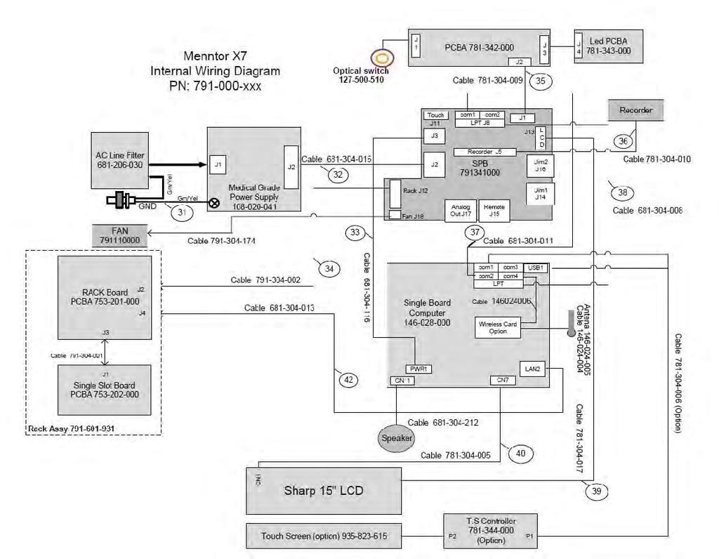
178
179 Menntor X7 Service Manual Menntor X7 BEZEL Assembly B-12 Mennen Medical
180
181
182 Menntor X7 Service Manual Menntor X7 Rear Cover Assembly B-14 Mennen Medical
183
184 Menntor X7 Service Manual Menntor X7 Bottom Assembly B-16 Mennen Medical
185
186 Menntor X7 Service Manual Menntor X7 Rack Bottom Assembly B-18 Mennen Medical
187
188 Menntor X7 Service Manual Menntor X7 Rack Assembly B-20 Mennen Medical
189
190
191 Menntor X7 Service Manual MX57 Top Assembly B-22 Mennen Medical
192
193
194
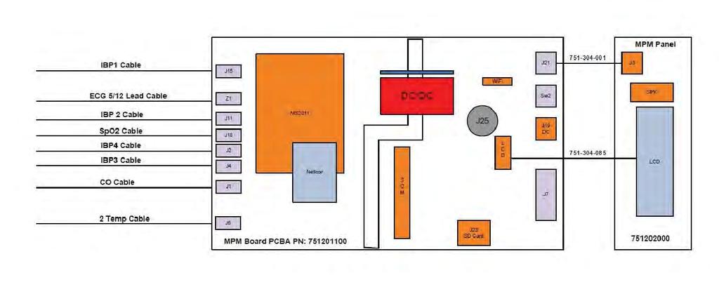
195
196 Menntor X7 Service Manual MX57 Main Board Assembly B-24 Mennen Medical
197
198
199
200 Menntor X7 Service Manual MX57 Assemblies MX57 Input Connections Assembly B-26 Mennen Medical
201
202
203
204 Menntor X7 Service Manual MX57 Front Assembly B-28 Mennen Medical
205
206
207
208 Menntor X7 Service Manual Spiro Module Assembly B-30 Mennen Medical
209
210 Menntor X7 Service Manual EtCO2 Unit Assembly B-32 Mennen Medical
211
212 Menntor X7 Service Manual B-34 Mennen Medical
. 2. Attach the Light guides X 4 units (2 in Figure C-1). 2 1 Figure C-1 3. Attach the Front Panel PCBA (3 in Figure C-2) 4. Place the Speaker (4 in Figure C-2) 5.")
213 APPENDIX C: STEP-BY-STEP ASSEMBLIES Assembling MX57 Step-by-Step You need to assemble the MPM panel and the MPM base, connect the panel to the base and close the box. To assemble the of MPM Panel : 1. Attach the rubber (1 in Figure C-1). 2. Attach the Light guides X 4 units (2 in Figure C-1). 2 1 Figure C-1 3. Attach the Front Panel PCBA (3 in Figure C-2) 4. Place the Speaker (4 in Figure C-2) 5. Clean LCD and LCD protection cover. 6. Place the LCD protection cover (5 in Figure C-2) Mennen Medical C-1
. 8.")

 10.")
214 Menntor X7 Service Manual 3 5 Figure C Place the LCD (6 in Figure C-3). 8. Connect the LCD Invertor cable (7 in Figure C-3). 6 7 Figure C-3 9. Connect the LCD plate using the 5 screws (7 in Figure C-4) 10. Glue the Speaker using RTV (7 in Figure C-4). 8 9 Figure C-4 C-2 Mennen Medical
. 1 Figure C-6 3.")
 between the base and the panel (2 in Figure C-7). 5.")
215 Menntor X7 Service Manual To assemble MX57: 1. Place the MX57 PCBA into the Base box (1 in Figure C-5). 1 Figure C-5 2. Attach the sticker close to LCD interface connector (1 in Figure C-6). 1 Figure C-6 3. Connect the power cable between the base and the panel (1 in Figure C-7). 4. Connect LCD interface cable (flex cable) between the base and the panel (2 in Figure C-7). 5. Push the flex cable to the front. Mennen Medical C-3
.")


216 Menntor X7 Service Manual 1 2 Figure C-7 6. Use the screws to screw the panel to the base (1 in Figure C-8). 7. Connect MX57 battery and turn on MX57 (2 in Figure C-8). 8. Verify LCD is working and turn off MX Assemble connectors panel (3 in Figure C-8) Figure C Screw on the top of the Connectors panel with screws (1 in Figure C-9). 1 1 Figure C-9 C-4 Mennen Medical


217 Menntor X7 Service Manual 11. Attach the antenna covers (1 in Figure C-10). 1 Figure C Attach the battery cover (1 in Figure C-11). 1 Figure C-11 Mennen Medical C-5
: a. Power Splitter (1 in Figure C-12) b. AC line filter with fuses (2 in Figure C-12) c.")
218 Menntor X7 Service Manual Assembling Menntor X7 Step-by-Step You need to assemble the chassis and the front panel, connect the chassis to the panel, connect the rest of the components and close the box. To assemble the chassis: 1. Connect the components to the chassis in the following order (see Figure C-12): a. Power Splitter (1 in Figure C-12) b. AC line filter with fuses (2 in Figure C-12) c. Power supply (3 in Figure C-1) d. Earth connection with strips ( 4 in Figure C-12) e. Auxillary metal part (5 in Figure C-12) f. Power and front cables (6 in Figure C-12) g. Fan (7 in Figure C-12) h. CPU stands (*4) and CPU ( 8 in Figure C-12) Figure C-12 C-6 Mennen Medical
 d. Recorder cable (4 in Figure C-13) e. Recorder (5 in Figure C-13) Figure C-13 To assemble the front panel: 1.")
219 Menntor X7 Service Manual 2. Connect the components to the chassis in the following order (see Figure C-13): a. CPU (1 in Figure C-13) b. COM, Touch LPT and recorder cables (2 in Figure C-13) c. CPU Power, LVDS & Inverter cables (3 in Figure C-13) d. Recorder cable (4 in Figure C-13) e. Recorder (5 in Figure C-13) Figure C-13 To assemble the front panel: 1. "Light guide" at the front panel ( 1 in Figure C-14). Figure C-14 Mennen Medical C-7
 Figure C-15")
and touch panel / normal transparent panel ( 3 in Figure")
220 Menntor X7 Service Manual 2. "key rubber" and the LEDs board ( 2 in Figure C-15) Figure C Opto Switch ( 1 in Figure C-16), Keyboard PCBA ( 2 in Figure C-16)and touch panel / normal transparent panel ( 3 in Figure C-16) Figure C-16 C-8 Mennen Medical


221 Menntor X7 Service Manual To assemble the Menntor X7: 1. Connect the front panel to the Chassis Figure C Connect the components to the bodyin the following order (see Figure C-18) a. Rack PCBA b. Rack Cable c. Single Board PCBA d. Cable e. Touch PCBA f. Speaker. Figure C-18 Mennen Medical C-9


.")
222 Menntor X7 Service Manual 3. Connect the Rack to the Menntor body. 4. Attach the UIM plastic cover. Figure C-19 Figure C Assemble the locking mechanism (see Figure C-21and Figure C-22). Figure C-21 C-10 Mennen Medical


223 Menntor X7 Service Manual Figure C Attach the Rear Cover then the Rack Base. Figure C-23 Figure C-24 Mennen Medical C-11
224 Menntor X7 Service Manual C-12 Mennen Medical
225 APPENDIX D: CEREBRALOGIK Introduction The CerebraLogik system is a Menntor X7 module designed to monitor EEG and display long term Amplitude Integrated EEG (aeeg). The Menntor X7 monitor uses the CerebraLogik front end amplifier to record two channels of EEG. The CerebraLogik is a stand alone unit to be attached to a basinet or patient bed. Its interface cable is connected to the UIM input of the monitor, and can be activated via the UIM menu. The EEG display shows real time EEG with history of EEG compressed as Amplitude Integrated EEG aeeg, showing 3 hours of EEG. CAUTION! It is not allowed to connect the interface cable to any equipment, other than Menntor X7 monitors. Indications for Use The intended use of the CerebraLogik is to monitor the state of the brain by acquisition of EEG signals, and display the stored EEG in a compressed form of Amplitude Integrated EEG - aeeg and in conjunction with other clinical data. WARNING!!! EEG monitoring is intended for use in hospitals only, and under the direct supervision of a licensed healthcare practitioner trained in its proper use. CAUTION! The dual channel EEG monitoring does not replace full EEG examination. WARNING!!! CerebraLogik is not defibrillator proof; in case of defibrillation; disconnect the EEG electrodes from the CerebraLogik.. Mennen Medical D-1

226 Menntor X7 Service Manual Compliance Menntor X7 bedside monitor is also designed to comply with the international EMC requirements for medical electrical equipment IEC CerebraLogik Storage CAUTION! If the CerebraLogik is stored for a long period of time, it is recommended to store it on it's original packaging. Icons The following icons appear on the CerebraLogik adjacent to the electrode input connectors. Table 1: Icons Attention, consult accompanying documents (Service to be performed by qualified technician.) Type BF applied part Refer to instruction manual/ booklet Restricts the sale and use of this instrument to qualified medical personnel only. Not for use in explosive gas environment Electrical and electronic equipment - Dispose according to local regulation Date of manufacture CE Mark D-2 Mennen Medical

227 Menntor X7 Service Manual Patient Safety Patient safety is assured by double isolation between the EEG input and the electrical power. The double isolation prevents summation of leakage between the EEG electrodes and other applied parts. CAUTION! CerebraLogik is not intended for use during surgery and electrosurgery. Figure D-1: CerebraLogik Module CerebraLogik is equipped with sockets for 5mm DIN connectors, for use with disposable cup or needle electrodes with wires. Use Grass Safelead Surface or Subdermal needle electrodes or equivalent. The sockets are marked as Left +, Left, Right +, Right, REF. The five sockets build 2 channels of EEG in the following matter: The two Left inputs comprise Channel 1, marked as "Left" and the two Right inputs comprise Channel 2, marked as "Right". Both channels use the REF as a Reference point. Both channels are differential with high common mode rejection, thus preventing interference from devices such as pacemakers and peripheral stimulators. Each EEG channel can be displayed on the Menntor X7 together with its corresponding aeeg channel. Note: The DIN connectors have protected female plugs, thus preventing the possibility that the plug touchs any conductor other than the CerebraLogik sockets. Mennen Medical D-3

228 Menntor X7 Service Manual WARNING!!! Use of electrodes that do not use DIN connectors is forbidden and may jeopardize the patient safety. CAUTION! Conductive parts of ELECTRODES, including the NEUTRAL ELECTRODE, should not come in contact with other conductive parts including earth. CerebraLogik Label Figure D-2: CerebraLogik label CerebraLogik - Waveforms and Display Modes Menntor X7 equipped with CerebraLogik, can display two sections for each channel in parallel: real time EEG and aeeg waveforms. The real time EEG is shown under the correlating aeeg of each channel. The aeeg shows up to 3 hours with the current time at the right side of the panel. During the recording you can see the historical EEG waveforms in parallel as full disclosure of the specific patient in a special "History panel". The display can be configured in a variety of modes: EEG real time waveform display EEG real time with aeeg Very big numbers with one EEG and aeeg display EEG waveform plus one hour aeeg EEG and aeeg History panel D-4 Mennen Medical
 represents good quality and 5 worse quality or faulty electrode.")
229 Menntor X7 Service Manual Quality Bar and Graph The EEG signal quality is shown by a vertical resistance bar to the right of the EEG waveform. The historical quality is shown on the aeeg panel by a superimposed resistance line, with a scale of 0 to 5. Where zero (0) represents good quality and 5 worse quality or faulty electrode. CerebraLogik Full Disclosure Figure D-3: aeeg + EEG real time CerebraLogik records the EEG and aeeg during the entire time the patient is connected to the Menntor X7 and to the CerebraLogik electrodes. You can export the full data at the end of the procedure or, if desired, sections of CerebraLogik recording can be exported before the patient is dismissed. You can choose the sections manually. Viewing of the exported data is done on any PC using the CerebraLogik Viewer software by Mennen Medical. Operating Menntor X7 Monitor with CerebraLogik Preparing for Operation To prepare the CerebraLogik for operation 1. Connect the CerebraLogik to one of the UIM inputs of the Menntor X7 monitor 2. From the Vital Signs menu select the relevant UIM channel Mennen Medical D-5
230 Menntor X7 Service Manual 3. Select CerebraLogik and activate 4. Attach the EEG scalp electrodes 5. Secure the CerebraLogik to a convenient location near the patient's head using the attachment clip. Electrode Location The two channels are marked as Left and Right. You can use either one or both channels, providing that a reference electrode is connected on the scalp. If two channels are used, a third Cross channel that is the difference between the Left and Right channel is also available for display. in Figure D-4: shows the electrode location for single or dual channel aeeg as recommended by El-Dib et al (2009)*. A B Figure D-4: Electrode location for aeeg (El-Dib et al (2009). A: Single channel electrode placement (P3-P4); B: Dual Channel Placement (C3-P3 and C4-P4) 1 1.* El-Dib M, Change T, Tsuchida TN, Clancy RR. Amplitude-Integrated electroencephalograpy in neonates Pediatr Neurol 2009;41: D-6 Mennen Medical
231 Menntor X7 Service Manual Technical Alarm If any of the electrodes is not connected, a technical alarm is created and the quality bar appears full. A label with the faulty electrode is presented to the right of the Realtime or History panels. For example: EEG Lead L (+) off, or EEG Lead R ( - ) for the Left positive electrode, or the Right negative electrode failure respectively. If more than one electrode is not connected or the reference electrode is not connected, the following message is displayed: EEG Check Electrodes. CerebraLogik Service CerebraLogik service is limited to: Replacing the complete module Replacing plastic parts Note: For repairs, send the module to Mennen Medical. CerebraLogik Drawing See the following pages for CerebraLogik drawing. Mennen Medical D-7
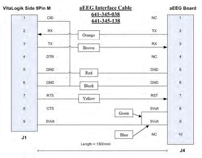
232
Menntor X7 Specification
 Specification is a modular monitor consisting of a Host Monitor a Multi Parameter Module, and two Single Parameters Modules. Host Monitor Specification Hardware and Parameters is a modular monitor with
VITALOGIK= 4000 / 6000 Series Configured Patient Monitors SERVICE MANUAL FDM REV.A
 VITALOGIK= 4000 / 6000 Series Configured Patient Monitors SERVICE MANUAL FDM-000-001 REV.A September 2013 Conformity according to the Council Directive 93/42/EEC concerning Medical Devices Manufacturer
OMNI TOUCH SCREEN PATIENT MONITOR
 OMNI TOUCH SCREEN PATIENT MONITOR OMNI Intuitive Designed for a fast paced work environment, the Infinium Omni patient monitor offers an extremely simple and adaptable user interface. Patient information
Omni (K) PATIENT MONITOR
 PATIENT MONITOR") Omni (K) PATIENT MONITOR Omni (K) Intuitive Designed for a fast paced work environment, the Infinium Omni (K) patient monitor offers an extremely simple and adaptable user interface. Patient information
Omni (K) PATIENT MONITOR Omni (K) Intuitive Designed for a fast paced work environment, the Infinium Omni (K) patient monitor offers an extremely simple and adaptable user interface. Patient information
DPM Summary of Features and Benefits
 Summary of Features and Benefits PAT I E N T M O N I TO R 12.1" TFT display, configurable up to 8 waveforms, enables maximum data analysis of your most critical parameters Standard features include 3/5-lead
Vitalmax 4000 CL Product Specifications
 Page 1 of 5 Vitalmax 4000 CL 510 Garden Avenue North, Clearwater, FL 33755 Phone: (727) 442-8118 Fax: (727) 443-7257 A. Mechanical Description Size 10" H x 13" W x 8"D (25 cm x 33 cm x 20 cm) Weight 18
1 Appendix - Product Specifications
 1 Appendix - Product Specifications WARNING The patient monitor may not meet its performance specification if stored or used outside the manufacturer s specified temperature and humidity range. 1.1 Safety
PM-9000 Express Portable Patient Monitor
 FEATURES 12.1" color TFT with maximum 8 waveforms Rich in ECG software OxyCRG software available 40 seconds full-disclosure waveforms review Drug dose calculation Bed to bed view Networking capacity Multi-Gas/O2
Product Specifications
 1.Safety Specifications 1.1Product Classification Class Type of protection against electric shock Specification Class I, with internal power supply Degree of protection against electric shock Anti-defibrillation:
5/ 5i/ 5c/ 7/ 7i/ 7c/ 5 elite/ 5i elite/ 5c elite/ 7 elite/ 7i elite/ 7c elite
 Summary The élance 5 / 5i / 5c / 7 / 7i / 7c /5 elite/ 5i elite / 5c elite / 7 elite / 7i elite /7c elite are integrated vital signs monitors with widescreen resistive touchscreen display. The monitors
Passport 12m and Passport 17m BEDSIDE MONITOR GUIDELINE 5.21 Software Version NAME: HOSPITAL: DATE: VALIDATOR: Performed
 Passport 12m and Passport 17m BEDSIDE MONITOR GUIDELINE 5.21 Software Version This document is a guideline only to be used as an aid to comprehensive Inservice training. NAME: HOSPITAL: DATE: VALIDATOR:
PATIENT MONITORING SYSTEMS
 PATIENT MONITORING SYSTEMS Patient Monitoring Systems DESIGN FEATURES HEYER VizOR is our premium solution for sophisticated patient monitoring applications. VizOR comes in its standard configuration with
PATIENT MONITORING SYSTEMS
 PATIENT MONITORING SYSTEMS PATIENT MONITORING SYSTEMS The benefits of HEYER Scalis to meet the market situation HEYER Scalis function & features make it fit to match the requirement of standard applications
PATIENT MONITORING SYSTEMS
 PATIENT MONITORING SYSTEMS Patient Monitoring Systems DESIGN FEATURES HEYER VizOR is our premium solution for sophisticated patient monitoring applications. VizOR comes in its standard configuration with
SPECIFICATION FOR MULTIPARAMETER MONITOR
 SPECIFICATION FOR MULTIPARAMETER MONITOR Eight channel high resolution colour TFT display with 12.1" screen size and auto spacing User Selectable Display formats and waveform colours. ECG monitoring -
Multi-Parameter Patient Monitor
 KIZLON Multi-Parameter Patient Monitor Email: info@kizlonmedical.com Website: www.kizlonmedical.com Multi-Parameter Patient Monitor KPM-A1 Series s of Portable Patient Monitor KPM-A1 Series has color TFT
MRI Patient Monitoring System (Model )
") MRI Patient Monitoring System (Model 865214) INSTRUCTIONS FOR USE Revision C English A Specifications Specifications PATIENT SAFETY GENERAL Conforms to UL STD 60601-1. Certified to CAN/CSA STD C22.2 No.
MRI Patient Monitoring System (Model 865214) INSTRUCTIONS FOR USE Revision C English A Specifications Specifications PATIENT SAFETY GENERAL Conforms to UL STD 60601-1. Certified to CAN/CSA STD C22.2 No.
T1 BEDSIDE MONITOR GUIDELINE
 APPENDIX A T1 BEDSIDE MONITOR GUIDELINE 5.23 Software Version This document is a guideline only to be used as an aid to comprehensive Inservice training. NAME: HOSPITAL: DATE: VALIDATOR: A. OVERVIEW 1.
Meditec M700 Series Patient Monitors
 Meditec M700 Series Patient Monitors Advanced Monitoring Parameters ECGCardioTecTM 1lead ECG Analysis 1lead ECG to analyze I, II,III,aVR, avl, avf, V1V6 and display these waveforms on the same screen Two
OMNI Express VS VERSATILITY IN VITAL SIGNS
 OMNI Express VS VERSATILITY IN VITAL SIGNS OMNI Express VS TOUCHSCREEN easy and intuitive to use PORTABLE weighs less than 6lbs MOBILE backup battery powered The Omni Express VS is a new intuitive approach
SureSigns VS4. Vital Signs Monitor Technical Data Sheet
 SureSigns VS4 Vital Signs Monitor Technical Data Sheet The SureSigns VS4 is a vital signs monitor that measures blood pressure, pulse rate, oxygen saturation (SpO 2 ), and temperature. The VS4 monitor
B40 Patient Monitor. Affordable clinical excellence. Advanced clinical parameters. Ease of use for fast decision-making. Performance and reliability
 B40 Patient Monitor Affordable clinical excellence Patients with acute, life-threatening conditions need the best possible care. The B40 Monitor from GE Healthcare provides a continuous flow of quality
CLEO VERSATILITY IN VITAL SIGNS
 CLEO VERSATILITY IN VITAL SIGNS CLEO PORTABLE weighs less than 3 lbs TOUCHSCREEN easy and intuitive to use MOBILE backup battery powered The Cleo is a new and intuitive approach to patient vital signs
General Skills. yes. Device controls, buttons, indicators, and connectors
 HeartStart MRx Skills Checklist This checklist assesses qualified medical personnel s understanding of MRx operation after instructor-based training. Perform a quick skills assessment using the General
Cost-effective way to tailor anesthesia
 Cost-effective way to tailor anesthesia For over 20 years, Heal Force has been working closely with doctors and our industrial partners to develop advanced but affordable hardware and software, for optimizing
Propaq LT Outline Train the Trainer
 Train the Trainer A. Propaq LT and LTR Propaq LT Standalone monitor Propaq LTR Monitor that has the wireless Acuity feature enabled 1. Lightweight (Less than 2 pounds) 2. Uses rechargeable lithium ion
qube mini Overview
 D a t a S h e e t qube mini Overview The 91389 qube mini is a compact, robust, and light-weight patient monitor with extensive clinical usability. Key features of the qube mini monitor include: Eye-level
DPM4 Bedside Monitor Default Settings
 DPM4 Bedside Monitor Default Settings Hospital: Department: Clinical / Sales / Service Representative: (** Patient Size Dependent) Date: Software Version: (* Optional) System Menu System Setup Menu Face
Atlas Monitor Outline Train the Trainer
 Atlas Monitor Outline Train the Trainer A. ATLAS Monitor 1. Atlas Monitor is not designed for use on children younger than 3 years old. 2. Weight: 9.5lbs to 13.2 lbs, depending on configuration 3. Variable
SECTION L MONITORING EQUIPMENT
 BREATH-ALERT Y1090 BREATH-ALERT MK4 MONITOR The Breath-Alert Mk4 respiratory monitor is a simple yet sensitive and reliable device for monitoring breathing. A heat-sensitive sensor is placed in the breath
Alarm and Measurement Default Settings
 Alarm and Measurement Default Settings 39 Default Settings Appendix Alarm and Measurement Default Settings Settings are only entered once per table row if they are the same for all patient categories.
M8000VET /M9000VET Veterinary Monitor User s Manual
 M8000VET /M9000VET Veterinary Monitor User s Manual Guangdong Biolight Meditech Co., Ltd. Address: Innovation First Road, Technology Innovation Coast, Jinding, Zhuhai, P.R.CHINA Tel: +86-756-3399900 Fax:
OPERATOR S MANUAL. NPB-4000/4000C Patient Monitor
 OPERATOR S MANUAL NPB-4000/4000C Patient Monitor Nellcor Puritan Bennett Inc. is an affiliate of Tyco Healthcare. Nellcor, Nellcor Puritan Bennett, Durasensor, C-LOCK, Oxisensor II, Dura-Y, and the Nellcor
GE Healthcare. Quick Guide. Dash 2500 Patient Monitor
 GE Healthcare Quick Guide Dash 2500 Patient Monitor Hardkeys Main Menu Hide menu and view entire waveform screen Display the large numeric vital signs Review or change alarm limits for all operating parameters
PULSE OXIMETER PACKAGE
 instrumentation and software for research PULSE OXIMETER PACKAGE CANL-425SV-A USER S MANUAL DOC-095 Rev. 1.6 Copyright 2012 All Rights Reserved Med Associates Inc. P.O. Box 319 St. Albans, Vermont 05478
User s Guide. Cardell Touch Veterinary Vital Signs Monitor. For Models:
 Cardell Touch Veterinary Vital Signs Monitor For Models: 8013-001 8013-002 8013-003 8013-004 User s Guide TP200 Rev. A 003-2840-00 Rev. AA2 (6/20/18) Software Version V4.0.X Product Information Dealer:
HeartStart XL+ Configuration Worksheet
 HeartStart XL+ Configuration Worksheet The following pages show the available configuration options for the HeartStart XL+. Please enter your configuration choices and save this worksheet for your records.
OPERATOR S MANUAL. Patient Monitor M20. EU representative TECNOMED 2000 S.L. Valencia, Madrid Spain
 OPERATOR S MANUAL Patient Monitor M20 EU representative TECNOMED 2000 S.L. Valencia, 25-28012 Madrid Spain Manufacturer Mediana Co., Ltd. Wonju Medical Industry Park, 1650-1 Donghwa-ri, Munmak-eup, Wonju-si,
T1 Monitor/Module Default Settings
 Hospital, City, ST Department Clinical/Sales/Service Representatives Date Software Version Signature,Title Maintenance System time Date format: Time format: 12 24 Manage Config Department: General Select
Ultraview SL2400 With Wireless-LAN-Option
 Ultraview SL2400 With Wireless-LAN-Option Spacelabs Healthcare Connecting Innovation with Care Spacelabs Healthcare is fully committed to making strong connections: between clinicians and their patients;
Patient Monitoring System YM5500. Service Manual
 Patient Monitoring System YM5500 Service Manual SERVICE MANUAL For YM5500 Patient Monitor Mediana Co.,Ltd. 231-6 Nonhyun-Dong, Kangnam-Ku, Seoul, Korea Tel: (82) 2 542 3375 Fax: (82) 2 542 7447 YM5500
ENSEMBLE Central Nurse Station USER MANUAL
 ENSEMBLE Central Nurse Station USER MANUAL DDM-555-001 Rev C. Nov. 2014 Conformity according to the Council Directive 93/42/EEC concerning Medical Devices Manufacturer s Name : Mennen Medical Ltd. 4 Hayarden
www. szcomen. com COMEN - SHARE WITH THE WORLD
 COMEN - SHARE WITH THE WORLD Agenda COMEN - SHARE WITH THE WORLD C80 Introduce C80 Market position Hardware Software price C80 C90 C60 C30/C90A C50 STAR8000D STAR8000C STAR8000B STAR8000A Products positioning
GE Healthcare. Dash Variable-Acuity Monitoring
 GE Healthcare Dash Variable-Acuity Monitoring The RIGHT information. Right now. In your busy schedule, having accurate patient information at your fingertips is critical. And there is no time for false
SERVICE MANUAL YM6000 Patient Monitor
 SERVICE MANUAL YM6000 Patient Monitor EU representative TECNOMED 2000 S.L. Valencia, 25 28012 Madrid Spain Manufacturer Mediana Co., Ltd. Wonju Medical Industry Park, 1650 1 Donghwa ri, Munmak eup, Wonju
OVEN INDUSTRIES, INC.
 OVEN INDUSTRIES, INC. OPERATING MANUAL Model 5C7-252 TEMPERATURE CONTROLLER With PLC Inputs Introduction Thank you for purchasing our controller. The Model 5C7-252 is an exceptionally versatile unit and
Nellcor Bedside SpO 2 Patient Monitoring System, PM100N
 Nellcor Bedside SpO 2 Patient Monitoring System, PM100N In-Service Presentation Nellcor Bedside SpO 2 Patient Monitoring System is CE marked and commercially av ailable in European Union countries. Nellcor
Infinity M300 Patient Worn Monitoring
 Infinity M300 Patient Worn Monitoring Managing the care of ambulatory patients is challenging because you need to balance mobility with patient safety. The innovative Infinity M300 patientworn monitor
Capnostream 20p Bedside Capnography Monitor. The only integrated, complete picture of oxygenation and ventilation 1
 Capnostream 20p Bedside Capnography Monitor The only integrated, complete picture of oxygenation and ventilation 1 Smart Capnography and Pulse Oximetry Technology Smart Capnography is a suite of algorithms
QAM.L L550 series. Patient Monitor Manual QAM.L
 QAM.L550.1112.2 L550 series Patient Monitor Manual QAM.L550.0915.3 Preface This manual has been provided to give detailed descriptions on DARAY s L550 patient monitor, covering the performance, operation
Temperature + Humidity (%RH) Control & Recording System with 8 / 16 Channel Mapping. Touch Panel PPI
 Control & Recording System with 8 / 16 Channel Mapping. Touch Panel PPI") HumiTherm Ultra Temperature + Humidity (%RH) Control & Recording System with 8 / 16 Channel Mapping Mapping Unit Micro PLC Control Unit Touch Panel Touch Operation Panel PPI HumiTherm Ultra GSM Module
HumiTherm Ultra Temperature + Humidity (%RH) Control & Recording System with 8 / 16 Channel Mapping Mapping Unit Micro PLC Control Unit Touch Panel Touch Operation Panel PPI HumiTherm Ultra GSM Module
HBP Patient Monitor. Operator s Manual. EU representative OBELIS S.A Bd. Général Wahis, Brussels, Belgium.
 Patient Monitor HBP-2070 Operator s Manual EU representative OBELIS S.A Bd. Général Wahis, 53 1030 Brussels, Belgium Local distributor Manufacturer Mediana Co., Ltd. Wonju Medical Industry Park, 1650-1
I/A Series 716C 1/16 DIN Temperature Controller
 Product Specifications I/A Series 716C 1/16 DIN Temperature Controller PSS 2C-1B5 A The Foxboro 716C is a powerful compact, 1/16 DIN, microprocessor-based temperature controller that offers a variety of
User Manual. Digi-Sense TC9500 Advanced Multiparameter Temperature Controller with Thermocouple, Thermistor, and RTD Inputs
 User Manual Digi-Sense TC9500 Advanced Multiparameter Temperature Controller with Thermocouple, Thermistor, and RTD Inputs Models 89800-03 and 89800-04 THE STANDARD IN PRECISION MEASUREMENT Table of Contents
740 SELECT. Multi-Parameter Monitor
 Multi-Parameter Monitor User Manual Addendum - CO2 Parameters This User Manual Addendum describes the features and operations of the Multi-Parameter monitor: Software Version 2.2 or above. 21-22-0333 Rev
The information in this document is subject to change without notice.
 Operator s Manual NOTICE The information in this document is subject to change without notice. Welch Allyn makes no warranty of any kind on this material, including but not limited to, the implied warranties
APC BC300 Series 40kW 208/450/480V User Guide
 APC BC300 Series 40kW 208/450/480V User Guide Copyright 2002 APC Denmark ApS This manual is subject to change without notice and does not represent a commitment on the part of the vendor Thank You Thank
MICROCAPSTAR End-Tidal CO 2 Analyzer Instruction Manual
 MICROCAPSTAR End-Tidal CO 2 Analyzer Instruction Manual Read instructions carefully before operating this device. ❶ This device is not to be used for Human Life Support applications. ❷ To avoid possible
PACSystems* RX3i. Thermocouple Input Module, 12 Channels, IC695ALG412. GFK-2578B October 2011
 October 2011 PACSystems* RX3i Thermocouple Input Module, 12 Channels, IC695ALG412 The PACSystems * Thermocouple Input module IC695ALG412 provides twelve isolated differential thermocouple input channels.
SERVICE MANUAL. Patient Monitor M30. EU representative TECNOMED 2000 S.L. Valencia, Madrid Spain
 SERVICE MANUAL Patient Monitor M30 EU representative TECNOMED 2000 S.L. Valencia, 25-28012 Madrid Spain Manufacturer Mediana Co., Ltd. Wonju Medical Industry Park, 1650-1 Donghwa-ri, Munmak-eup, Wonju-si,
VS2000V Veterinary Vital Signs Monitor Operation Manual
 VS2000V Veterinary Vital Signs Monitor Operation Manual - English Version 1.0, July 2011 2011 UTECH Co., Ltd. All rights reserved. Table of Contents Table of Contents Warranty and Service Information...
BEDSIDE MONITORING Dash 3000/4000 V5
 BEDSIDE MONITORING Dash 3000/4000 V5 Quick Reference Guide 2004 General Electric Company PN: 0304-CS-QRGD Rev. A 2018408-010 BEDSIDE MONITORING Dash 3000/4000 V5 Quick Reference Guide Components Display
Transport Pro Patient Monitor Operator s Manual Software Version 2.1
 GE Healthcare Transport Pro Patient Monitor Operator s Manual Software Version 2.1 Transport Pro English 2024598-003 (CD) 2024579-020A (paper) 2007 General Electric Company. All rights reserved. The information
BeneVision Central Monitoring System. Quick Reference Guide
 BeneVision Central Monitoring System Quick Reference Guide NOTE: The Quick Reference Guide is not intended as a replacement to the Operating Instructions. Prior to operating equipment, the user must be
LORAIN CSP DC Power System
 DC Power for Business-Critical Continuity Key Features Compact flexibility provides more space for revenue generating equipment Constant power delivers more current at lower voltages to meet load or recharge
User Guide. Cardell Insight Veterinary Monitor. For Models: 8014 Blood Pressure Blood Pressure, Pulse Oximetry
 Cardell Insight Veterinary Monitor For Models: 8014 Blood Pressure 8015 Blood Pressure, Pulse Oximetry User Guide 003-2981-00 Rev. B (2/21/17) Software Version 1.2V Product Information Dealer: Date of
Vital Signs Monitor 300 Series
 Vital Signs Monitor 300 Series Directions for Use Software version 1.2X ii Welch Allyn Vital Signs Monitor 300 Series 2009 Welch Allyn. All rights are reserved. No one is permitted to reproduce or duplicate,
M9500 Patient Monitor User s Manual
 M9500 Patient Monitor User s Manual Guangdong Biolight Meditech Co., Ltd. Address: Innovation First Road, Technology Innovation Coast, Jinding, Zhuhai, P.R.CHINA Tel: +86-756-3399900 Fax: +86-756-3399989
User Manual. Digi-Sense TC9600 Advanced Multiparameter Temperature Controller with Thermocouple, Thermistor, and RTD Inputs
 User Manual Digi-Sense TC9600 Advanced Multiparameter Temperature Controller with Thermocouple, Thermistor, and RTD Inputs Models 89800-13 and 89800-14 THE STANDARD IN PRECISION MEASUREMENT Table of Contents
Vital Signs Monitor 300 Series
 Vital Signs Monitor 300 Series Directions for Use Software version 1.2X ii Welch Allyn Vital Signs Monitor 300 Series Copyright 2005 Welch Allyn. All rights are reserved. No one is permitted to reproduce
Specification for On-Line UPS Battery Monitoring and Data Management System
 1 Scope This specification defines the minimum requirements for a predictive on-line Battery Monitoring BMDMS with test, analysis, and remote monitoring control capabilities. Unless noted otherwise, the
Quick start guide. English
 Quick start guide English Read your entire Astral User Guide or Clinical Guide before use. The Astral device 1. Adapter port Can be fitted with single limb adapter, single limb leak adapter or double limb
Module Features are-configurable, no module jumpers to set
 December 2011 PACSystems* RX3i Isolated Thermocouple Input Module, 6 Channels, IC695ALG306 Isolated Thermocouple Input Module, 12 Channels, IC695ALG312 Isolated Thermocouple Input module IC695ALG306 provides
Checkout Procedure Manual
 Checkout Procedure Manual A-1020818 REV1 SmartMonitor2 Checkout Procedure 2015 Circadiance LLC. All rights reserved. Table of Contents Introduction... 2 Required Equipment... 2 Important Notes Read Carefully...
Ultraview SL Command Module Parameter Set ECG NIBP TEMP IP CO SpO2 Options SL Command Module: A B Our goals are simple:
 Ultraview SL2700 Spacelabs Healthcare - Connecting Innovation with Care Spacelabs Healthcare is fully committed to making strong connections: between clinicians and their patients; between technological
Instructions for Use Vista 120
 Instructions for Use Vista 120 To properly use this medical device, read and comply with these Instructions for Use. Patient Monitor Software 1.n Release date April 25 2011 Screen images Schematic renderings
Instructions for Use. Infinity Vista. Infinity Patient Monitoring Series
 Instructions for Use Infinity Vista Infinity Patient Monitoring Series Infinity Configured Monitoring Series Infinity Vista Instructions for Use WARNING: For a full understanding of the performance characteristics
CNAP MONITOR 500 HD QUICK GUIDE. This Quick Guide DOES NOT REPLACE the user manual!
 CNAP MONITOR 500 HD QUICK GUIDE This Quick Guide DOES NOT REPLACE the user manual! Version 07/2016 V1.5.5 EN 2 CONTENT SET UP MEASUREMENT NAVIGATION FAQs FUNCTIONS: FAST ACCESS Hemodynamic Parameters...5
LORAIN CIP 4890/48120 DC Power System
 DC Power for Business-Critical Continuity Key Features Compact flexibility provides rectifiers, distribution, and controller in one shelf Constant power delivers more current at lower voltages to meet
Vital Signs Monitor 300 Series
 Vital Signs Monitor 300 Series Directions for use Software version 1.2X ii Welch Allyn Vital Signs Monitor 300 Series 2014 Welch Allyn. All rights are reserved. To support the intended use of the product
Addendum to the Instructions for Use
 1Addendum Addendum to the Instructions for Use This addendum provides additional information for the IntelliVue Patient Monitor Instructions for Use: MP2: Part number 4535 643 06381 X2: Part number 4535
Measurements to guide your patient care
 Efficia CM12 patient monitor Measurements to guide your patient care Technical data sheet The Efficia CM Series patient monitors help you with monitoring, analyzing, recording, and alarming multiple physiological
Clinical Information Center Pro v5 (CIC Pro)
") GE Healthcare Clinical Information Center Pro v5 (CIC Pro) Participant Reference Guide Clinical Systems Clinical and Educational Development Welcome We would like to take a moment to thank you for choosing
GE Healthcare Clinical Information Center Pro v5 (CIC Pro) Participant Reference Guide Clinical Systems Clinical and Educational Development Welcome We would like to take a moment to thank you for choosing
V6 Vital Signs Monitor User s Manual
 V6 Vital Signs Monitor User s Manual Product Information Product Model: V6 Product Name: Vital Signs Monitor Manufacturer: GuangdongBiolightMeditech Co.,Ltd. After Service Contact Information: Address:
EasyLog Data Logger Series
 EasyLog Data Logger Series Overview EasyLog model EL-USB series products are a line of low cost, compact, battery-operated data loggers with built-in memory and USB interface. Each product in the line
INSTRUCTIONS FOR USE. IntelliVue X2. Multi-Measurement Module Release G.0 with Software Revision G.0x.xx. Patient Monitoring
 INSTRUCTIONS FOR USE IntelliVue X2 Multi-Measurement Module Release G.0 with Software Revision G.0x.xx Patient Monitoring Printed in Germany 09/08 *M3002-9001B* Part Number M3002-9001B 4512 610 28261 S
End-Tidal CO2 User Guide CAPNO3 T NIBP. SpO2. Ver Charmcare Co., Ltd.
 End-Tidal CO2 User Guide CAPNO3 T NIBP EtCO2 ECG SpO2 Ver 2.00 Charmcare Co., Ltd. -1- Table of Contents Indications for use statement 4 Warranty 4 Battery Replacement 4 Contact Us 5 Definition of Terms
Veterinary Portable Multi-parameter Patient Monitor. Operation Manual
 Veterinary Portable Multi-parameter Patient Monitor Operation Manual Content Chapter 1 Introduction... 1-1 1.1 General Information... 1-3 1.2 Screen Display... 1-4 1.3 Button Functions and Basic Operation...
Nellcor with OxiMax Technology Product Ordering Guide A Full Line of Oximetry Sensors and Monitors
 Nellcor with OxiMax Technology Product Ordering Guide A Full Line of Oximetry Sensors and Monitors Specialty sensors Forehead Sensor For patients with low perfusion; suitable for long-term monitoring Forehead
Nardalert S3 TM Non-Ionizing Radiation Monitor
 Patent Pending Nardalert S3 TM Non-Ionizing Radiation Monitor Field Replaceable Sensor Modules Color LCD Display Multi-Color Alarm LED s USB Interface for Data and Charging Comprehensive Software Included
Quick Reference Guide STAN S31 fetal heart monitor. Power ON/OFF. ST Analysis (Fetal ECG analysis)
") Quick Reference Guide STAN S31 fetal heart monitor Important! Read the STAN S31 User Manual. 1. 2. 3. 1 2 3 4 5 6 Transducer connectors 4. Function buttons Power switch 5. Information panel Fetal ECG (FECG)
Quick Reference Guide STAN S31 fetal heart monitor Important! Read the STAN S31 User Manual. 1. 2. 3. 1 2 3 4 5 6 Transducer connectors 4. Function buttons Power switch 5. Information panel Fetal ECG (FECG)
Galaxy Pulsar Plus Digital Battery Plant Controller
 Galaxy Pulsar Plus Digital Battery Plant Controller Features Supports up to 60 Power Modules rectifiers and converters Supports dual voltage plants, with rectifiers and converters Auto-sensing dual voltage
Manufacturer s Responsibility Only under the following circumstances will manufacturer be responsible for the safety, reliability and performance of t
 Preface Thank you for using M9500 patient monitor. In order to enable you to skillfully operate Monitor as soon as possible, we provide this user s manual with delivery. When you install and use this instrument
Architectural and Engineering Specification for a. Flash / Flare
 Architectural and Engineering Specification for a Flash / Flare June 27, 2014 Page 1 of 12 T1DA0115-001 Rev D This document is intended to provide performance specifications and operational requirements
SureSigns VS4 Vital Signs Monitor
 SureSigns VS4 Vital Signs Monitor INSTRUCTIONS FOR USE Release A.04 English Notice Proprietary Information This document contains proprietary information, which is protected by copyright. Copyright Copyright
Operator s Manual. Avant Pulse Oximeter and NIBP Monitor. English
 Operator s Manual Avant 2120 Avant 2120 Pulse Oximeter and NIBP Monitor 0123 English 1 CAUTION! CAUTION! Federal law (USA) restricts this device to sale by or on the order of a physician. Read this entire
B-40/B-41 Modulating Temperature Controller
 INSTALLATION & OPERATING INSTRUCTIONS B-40/B-41 Modulating Temperature Controller For Raytherm Boilers & Water Heaters H2 514-4001 WH2 2100-4001 Catalog No. 5000.70 Effective: 12-21-11 Replaces: NEW P/N
Refrigeration Controller Operator s Manual (HRC) PO Box 6183 Kennewick, WA
 PO Box 6183 Kennewick, WA") Refrigeration Controller Operator s Manual (HRC) PO Box 6183 Kennewick, WA 99336 www.jmcvr.com 1-509-586-9893 Table of Contents TABLE OF FIGURES...1 OVERVIEW OF THE HRC CAPABILITIES...2 INSTALLATION AND
Refrigeration Controller Operator s Manual (HRC) PO Box 6183 Kennewick, WA 99336 www.jmcvr.com 1-509-586-9893 Table of Contents TABLE OF FIGURES...1 OVERVIEW OF THE HRC CAPABILITIES...2 INSTALLATION AND
Connex Integrated Wall System 2.2 Software Version
 Connex Integrated Wall System 2.2 Software Version Clinical Inservice Presentation MC12931 1 Table of Contents Device Overview & Intended Use Power ON Power OFF Home Screen Navigation Spot Profile Intervals
Infinity M300+ Telemetry
 Infinity M300+ Telemetry The Infinity M300+ provides continuous surveillance of telemetry patients using the hospital s existing WiFi network The compact size supports patient mobility while the integrated