LC2011 FUEL LEVEL CONTROLLER 1 TANK
|
|
|
- Everett Emil Hill
- 5 years ago
- Views:
Transcription

1 LC2011 FUEL LEVEL CONTROLLER 1 TANK
2 Last Revision Date: March 9, 2016 For the most up-to-date information for this product and others, please contact Simplex, Inc. at (800) or visit us on the web at Many of the illustrations and instructions in this manual refer to the standard configuration for this product. If you have requested customizations, the drawings provided with your order take precedence; please refer to them for details specific to your order. If you have any questions, please contact Simplex at
3 Table of Contents 1 Warnings and Cautions... 1 Safety information symbols 1 Cautions 1 2 Nameplates and Placards Unpacking... 4 Included Components and Parts 4 Primary Inspection 4 4 Description and Specification... 5 Overview of Use 5 Capabilities 5 Safety 5 5 Installation... 7 Installing Wiring 7 Installing Cable Access 7 Installing Float Assemblies 7 Installing BMS monitoring 8 Installing Modbus TCP (If ordered) 8 Installing the Leak Sensor 8 Installing Dry Contact Alarms (If ordered) 8 6 Operating Instructions...10 System Check 10 Test Fill 11 Modbus Setup 11 Return Pump (If ordered) 11 Sequence of Operations 11 7 Alarms and Warnings...13 Alarms 13 Warnings 13 8 Maintenance/Troubleshooting...14 Preventative Maintenance 14 Troubleshooting 14 Appendix A PRODUCT WARRANTY...16
4 Table of Figures Fuel Level Controller...4 Float Assembly...4 Controller dimensions...6 Float Assembly Cable...7 Alarm History Main Screen Modbus Setup Troubleshooting Table... 15
5 1 WARNINGS AND CAUTIONS Safety information symbols The following images indicate important safety information: This General warning symbol points out important information that, if not followed, could endanger personal safety and/or property. This Explosion warning symbol points out potential explosion hazards. This Fire warning symbol points out potential fire hazards. This Electrical warning symbol points out potential electrical shock hazards. Cautions Improper operation of this equipment such as neglecting its maintenance or being careless can cause possible injury or death. Permit only responsible and capable persons to install, operate, and/or maintain this equipment. Potentially lethal voltages and amperages are present in these machines. Ensure all steps are taken to render the machine safe before attempting to work on the equipment. All hardware covered by this manual have dangerous electrical voltages and can cause fatal electrical shock. Avoid contact with bare wires, terminals, connections, etc., on the hardware, if applicable. Ensure all appropriate covers, guards, grounds, and barriers are in place before operating the equipment. If work must be done around an operating unit, stand on an insulated dry surface to reduce shock hazard. Do not handle any kind of electrical device while standing in water, while barefoot, or while hands or feet are wet. DAN- GEROUS ELECTRICAL SHOCK MAY RESULT. If trained personnel must stand on metal or concrete while installing, servicing, adjusting, or repairing this equipment, place insulative mats over a dry wooden platform. Work on the equipment only while standing on such insulative mats. The National Electrical Code (NEC), Article 250 requires the frame of the equipment to be connected to an approved earth ground and/or grounding rods. This grounding will help prevent dangerous electrical shock that might be caused by a ground fault condition or by static electricity. Never disconnect the ground wire. Wire gauge sizes of electrical wiring, cables, and cord sets must be adequate to handle the maximum electrical current Warnings and Cautions 1
6 2 Warnings and Cautions (ampacity) to which they will be subjected. Before installing or servicing this (and related) equipment, make sure that all power voltage supplies are completely turned off at their source. Failure to do so will result in hazardous and possibly fatal electrical shock. In case of accident caused by electric shock, immediately shut down the source of electrical power. If this is not possible, attempt to free the victim from the live conductor. AVOID DIRECT CONTACT WITH THE VICTIM. Use a nonconducting implement, such as a dry rope or board, to free the victim from the live conductor. If the victim is unconscious, apply first aid and seek immediate medical attention. Never wear jewelry when working on this equipment. Jewelry can conduct electricity resulting in electric shock or may get caught in moving components causing injury. Keep a fire extinguisher near the hardware at all times. Do NOT use any carbon tetra-chloride type extinguisher. Its fumes are toxic, and the liquid can deteriorate wiring insulation. Keep the extinguisher properly charged and be familiar with its use. If there are any questions pertaining to fire extinguishers, please consult the local fire department. The illustrations in this manual are examples only and may differ from your unit.
7 2 NAMEPLATES AND PLACARDS Nameplates and Placards 3


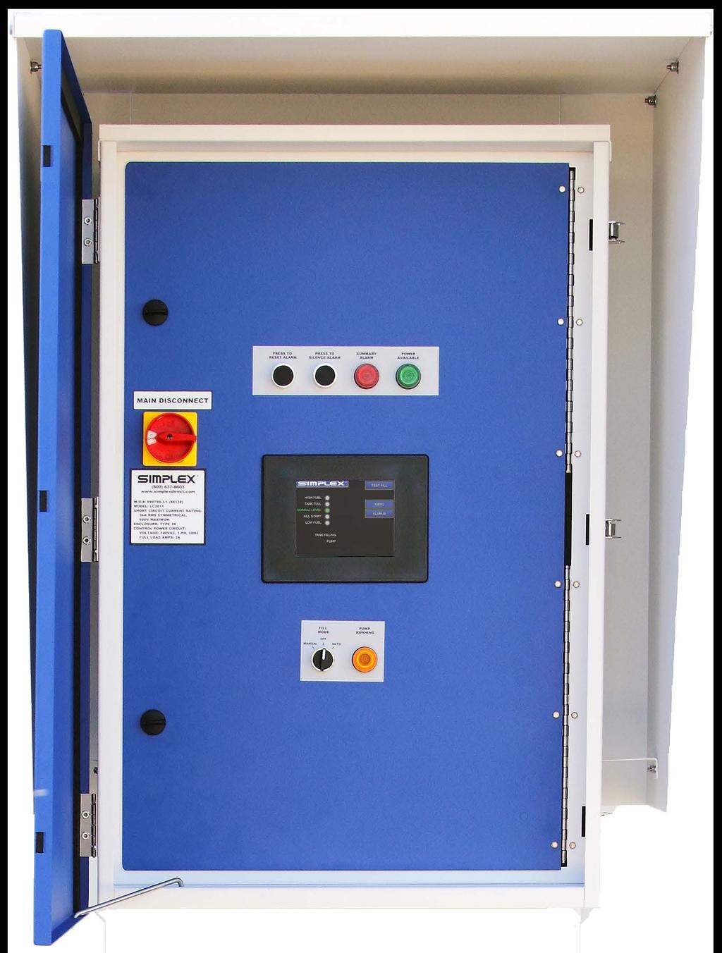
8 3 UNPACKING Included Components and Parts The following items are included with your LC2011 Fuel Level Controller. If any of the following are not included, please contact your Simplex representative or call Simplex Direct, Inc., at Primary Inspection Figure 1 Fuel Level Controller Fuel Level Controller Float Assembly(s) Manual Drawings package Preventative visual inspection of the shipping crate and the fuel level controller is advised. Never apply power to a fuel level controller before performing this procedure. The following four-point inspection is recommended before installation and as part of a 6month maintenance schedule: Figure 2 Float Assembly If any problems are observed during Primary Inspection, call Simplex 24 hours a 1. If the crate shows any signs of damage, examine the fuel level controller in the corresponding areas for signs of initial day at problems Check the entire outside of the cabinet for any visual damage, which could cause internal electrical or mechanical problems due to reduced clearance. 3. Check electrical connections for tightness. 4. Examine all accessible internal electrical components. 4 Unpacking
9 4 DESCRIPTION AND SPECIFICATION Overview of Use Capabilities Safety The LC2011 Fuel Level Controller provides intelligent control and monitoring of fuel level for day tanks and other storage tanks. The LC2011 monitors the fuel level in a tank, keeping it at least half full in standard configurations. When the fuel level drops to to the Fill Start level, it calls for fuel. When the fuel level reaches Full level, it cancels the call for fuel and can optionally return fuel to the main storage tank, if needed. With optional equipment, the fuel level controller can also display the fuel level in real time. With optional equipment, the fill controller can also shut down the generator if the fuel level reaches a critical low level and request a fill-up when the generator stops running. A touch screen provides control and monitoring, while communication options allow for central monitoring from a building management system (BMS/BAS). The Fuel Level Controller is network compatible with the entire Simplex Fuel System line and many other fuel systems. The LC2011 Fuel Level Controller is capable of monitoring and controlling round or rectangular tanks up to 100,000 gallons. The LC2011 can optionally control two ball valves - one to accept fuel, and another to return it to the main storage tank. The controller s main goal is to prevent overfilling of a tank and starving the generator s fuel injectors. To that end, the controller has three float level switches to ensure the fuel level remains in normal operating range. If the fuel level rises past the full level to the high fuel level, the controller will register an error. The controller can also monitor a leak sensor. When a leak is detected, the controller ceases to ask for fuel until the error is cleared. Description and Specification 5
10 EMERGENCY STOP POWER A AVAILABLE RESET PRESS TO PRESS TO SILENCE ALARM FILL MODE OFF MANUAL AUTO ALARM SUMMARY POWER B AVAILABLE Description and Specification Figure 3 Controller dimensions

11 5 INSTALLATION The Fuel Level Controller should be mounted at the tank it is monitoring, then wired to the power source, float assemblies, valves, and any other sensors or system integration connections. Installing Wiring Installing Cable Access Installing Float Assemblies If there are any questions about wiring the controller, please contact Simplex Inc. Simplex Inc. is not responsible for damage due to incorrect wiring installation. The controller must be completely wired prior to applying power. Failure to follow the wiring information and guide may result in product damage and loss of warranty coverage. If requested, startup services can be provided by Simplex Onsite, Inc. or Simplex, Inc. to check field wiring prior to applying power as well as assuring proper operation. To bring cabling into the fuel level controller, pull a hole into the cabinet at a location of your choosing and install a 3R-rated conduit connector for access. To install the float assembly, push the latch handles on the assembly down and slide the coupler off. Apply an appropriate threadlocker to the threads on the coupler and screw it into the appropriate fitting. Slide the assembly into the coupler and lift the latching arms until the assembly is locked into place. Connect: 1. Common wire to TB-B-2 2. Low Level Float wire to TB-B Fill Start Float wire to TB-B Full Level Float wire to TB-B High Level Float wire to TB-B-9 Figure 4 Float Assembly Cable Installation 7
12 Installing BMS monitoring If Modbus RTU-RS485 monitoring is desired, connect: 1. Wire Shielding to TB-C RS485+ to TB-C-2 3. RS485- to TB-C-3 Installing Modbus TCP (If ordered) Installing the Leak Sensor To install Modbus TCP: 1. Connect an Ethernet cable to the Ethernet jack on the Modbus controller. To install the Leak Sensor, connect it to TB-B as follows: 1. Sensor common to TB-B-2 2. Sensor signal to TB-B-15 Installing Dry Contact Alarms (If ordered) To connect the controller to external alarms, connect TB-R- 1-8 to your system as follows: For Summary alarm annunciation: 1. Common to TB-R-1 2. Normally Closed to TB-R-2 3. Normally Open to TB-R-3 For Leak alarm annunciation : 1. Common to TB-D-4 2. Normally Closed to TB-R-5 3. Normally Open to TB-R-6 For Not in Auto alarm annunciation: 1. Sensor common to TB-D-7 2. Normally Closed to TB-R-8 3. Normally Open to TB-R-9 For Low Level alarm annunciation: 1. Sensor common to TB-D Normally Closed to TB-R Normally Open to TB-R-12 8 Installation
13 For Critical Low Level alarm annunciation: 1. Common to TB-R Normally Closed to TB-R Normally Open to TB-R-15 For Critical High Level alarm annunciation: 1. Common to TB-R Normally Closed to TB-R Normally Open to TB-R-18 Installation 9

14 6 OPERATING INSTRUCTIONS Once installed, the Fuel Level Controller will not normally require further interaction to maintain the fuel level in the tank. In the event that you do need to use the interface, read the following section closely to avoid errors that may interfere with proper operation. When idle for a couple of seconds, the touch screen will go to sleep. To wake the fuel level controller from sleep mode, touch the screen to activate it. System Check Before filling the tank, check to see if any alarms (displayed in red) or warnings (displayed in yellow) have been registered. Alarms are indicated with red labels while warnings are indicated with yellow labels. Each active alarm or warning will appear one by one at the bottom of the screen no matter which screen is active. Figure 5 Alarm History Figure 6 Main Screen To view all of the alarms and warnings in list form, press the Alarms button, which is found on the main screen. From this screen, you can delete the inactive alarms one by one or clear them all by pressing the Clear All button. If an alarm or warning is still active, it will not clear. Press the Exit button to return to the main screen. All alarms are also indicated via an audible horn and light on the panel below the touch screen. To silence the horn, push the Silence Horn button above the touch screen. If there are any active alarms, contact the site supervisor immediately. 10 Operating Instructions

15 Test Fill Modbus Setup Return Pump (If ordered) Sequence of Operations The Test Fill button allows you to confirm that the panel is communicating with the fill pump correctly. While the day tank s fuel level is below the fill stop/tank full level, pressing the Test Fill button will cause the fuel level controller to send a call for fuel to the pump controller. Once the day tank s fuel level increases to the fill stop/tank full level, the call for fuel signal is terminated. If the filling operation is completed successfully, you can be assured the fuel level controller will operate correctly when needed. If you need to change the Modbus options to get the fuel level controller communicating with the rest of your system, press the Menu button on the Main Screen, then press Modbus Setup. A numeric keypad will pop up for the password. Enter to access the Modbus setup screen (Figure 7). Figure 7 Modbus Setup The Fuel Level Controller can be equipped with a return pump floatswitch, which readies the return pump when the fuel level rises to halfway between the Fill Start and Fill Stop levels. When the fuel reaches this level, the control panel will display Return Pump Armed. If the fuel reaches the High Fuel level, the lead return pump will activate, reducing the fuel level to the Return Pump Armed level. If the fuel reaches the Critical High level, the lag return pump will also activate. The Fuel Level Controller allows automatic fuel level monitoring and maintenance. As fuel is consumed and drops to the fill start level, the base tank controller generates a call for fuel signal to the master pump control panel to activate the lead fill pump. When the base tank reaches the tank full/fill stop level, the call for fuel signal is terminated. If the fuel level reaches the High level, the controller will activate the lead return pump (if ordered). If the fuel level reaches Operating Instructions 11
16 the optional Critical High level, the controller will activate the lag return pump as well. If the fuel drops below the fill start level to the low level, the controller will activate the lag fill pump. If the fuel level drops to the optional Critical Low level, the controller will shut down the generator immediately to prevent the equipment damage. 12 Operating Instructions
17 7 ALARMS AND WARNINGS Normally equipped, the Fuel Level Controller registers two alarms and two warnings. Alarms 1. Low Fuel: The fuel level has fallen below the Fill Start level. 2. High Fuel: The fuel level has risen above the Tank Full level. Warnings The Fuel Level controller presents warnings for situations that are noteworthy but not necessarily in need of immediate attention. Active warnings are displayed only on the touch screen by yellow indicators. 1. Tank Full: The tank has reached the full level and cannot be filled any further. 2. Fill Start: The tank fuel has fallen to the low level and is sending a call for fuel to the fuel system. Alarms and Warnings 13
18 8 MAINTENANCE/TROUBLESHOOTING Preventative Maintenance Trouble shooting Remove all power before servicing the Fuel Level Controller. Never operate or service a fill controller that is not grounded. The Fuel Level Controller is designed to require minimal maintenance. On a yearly schedule, the unit should be fully opened and cleaned out. At this time, it would be a good idea to disconnect power and tighten all connections to ensure proper operation. This would also be a good time to tighten any mounting hardware. To troubleshoot the Fuel Level Controller, a full set of drawings is required. Any electrical work should be performed by trained personnel. Simplex, Inc. is not liable for any damage or bodily harm. If additional help is required, contact Simplex or your local Simplex Onsite Branch for troubleshooting and onsite assistance. If there is a chance of power loss, add Panasonic CR2354 3V batteries to the PLC in order to retain the internal memory. Without batteries, the PLC will only retain its memory for a minimum of 4 days and a maximum of 3 weeks. To install or replace the PLC battery: 1. Press the retaining clip on the battery door down and open the battery door. 2. Place the battery into the coin type slot with the +, or larger, side out. 3. Close the battery door making sure that it locks securely in place. 4. Make a note of the date the battery was installed. The following table (Table 1) contains some common scenarios which you may face while operating the Fuel Level Controller. 14 Maintenance/Troubleshooting
19 Table 1 Troubleshooting Table Problem Cause Resolution Screen has gone to sleep Tap it to wake it up Screen is blank Control power isn t available Ensure that the control power switch is in the on position. If so, contact your facility s manager for power issues. The fuses are blown Replace fuses Panel does not respond when a button is pressed The RUN mode light on the PLC is off The stop-term RUN switch on the PLC isn t in term Enable PLC run mode Check PLC and put it in term Maintenance/Troubleshooting 15
20 Appendix A PRODUCT WARRANTY SIMPLEX, Inc., warrants the industrial electrical control, test and accessory equipment and parts and accessories thereof to be the kind and quality described in SIMPLEX s specifications and to be free from defects in material or workmanship under normal service, its obligations under this warranty being limited to repairing or replacing, at its option, any part or parts which shall, within twelve (12) months from date of shipment from its factory, as indicated by serial date code on the nameplate or sales records, be returned to SIMPLEX or an authorized SIMPLEX repair station, with transportation costs prepaid, and which its examination shall disclose to its satisfaction to have been thus defective. The provisions of this warranty shall not apply to any equipment, part or accessory which (a) has been improperly specified by buyer; (b) has been improperly stored or handled prior to placing in service; (c) has been improperly mounted or connected; (d) has not been operated within specifications stated on its nameplate, label or placard; (e) has not been properly maintained; (f) parts supplied by buyer for inclusion in finished equipment are not covered by this warranty; (g) components or assemblies specified by buyer with no substitution permissible that are not normally used by SIMPLEX. SIMPLEX reserves the right to reject warranty claims of any kind against assembled equipment, parts or material for which SIMPLEX has not received payment in full. Should buyer, at his own risk, elect to replace defective equipment or parts in the field rather than return equipment to SIMPLEX s factory or authorized repair station, SIM- PLEX will supply and invoice parts at normal prices upon receipt of buyer s bona-fide purchase order. Defective equipment or parts returned for in-warranty crediting in exchange for replacement parts must be returned within 45 days from date of shipment of replacement in order to qualify for warranty consideration. Defective equipment or parts returned after 45 days may be subject to a restocking charge of 20% or a minimum charge of $50.00, whichever is greater. This warranty is in lieu of all other warranties, express or implied, and all other obligations or liabilities on the part of SIMPLEX, and SIMPLEX neither assumes nor authorizes any other person to assume for it any other liability in connection with any such electrical control, test or accessory equipment or accessories or parts Product Warranty
21 WE WELCOME YOUR FEEDBACK! Simplex designs and manufactures Load Banks and Fuel Supply systems for power generation and liquid automation. Simplex is certified to ISO 9001:2008. Used world-wide for mission critical environments in manufacturing, technology, transportation, hospitals, schools, public utilities and the U.S. military, Simplex products provide solutions meeting exact requirements, from the simplest testing and proving equipment for backup generators to custom-designed and engineered mission-critical fuel systems. At Simplex, we are experts at building products that meet our customers exact requirements. For a complete listing of Simplex products visit Simplex welcomes your questions, comments, suggestions, compliments, and complaints as a way to continuously improve our service to you. Please call us at (24 hours a day) or visit


22 LOAD BANK RENTAL AND SERVICE CENTERS Simplex Onsite can place Load Banks, Cables, Transformers, and Fuel Polishers rentals as well as service technicians at your fingertips anywhere in the United States quickly and cost effectively. For information call or visit COLORADO Serving Colorado, Idaho, Montana, Nevada, Utah and Wyoming GEORGIA Serving Alabama, Florida, Georgia, North Carolina and South Carolina ILLINOIS Serving Illinois, Indiana, Kentucky, Michigan, Missouri and Tennessee MASSACHUSETTS Serving Connecticut, Delaware, Maine, Maryland, Massachusetts, New Hampshire, New Jersey, New York, Pennsylvania and Vermont MINNESOTA Serving Iowa, Minnesota, North Dakota, South Dakota and Wisconsin OHIO Serving Indiana, Michigan, Ohio, Pennsylvania (western) and West Virginia TEXAS Serving Arkansas, Louisiana, New Mexico, Oklahoma and Texas
23 5300 Rising Moon Road Springfield, IL Simplex, Inc Boggs Road Duluth, GA (800)
LC2011 FUEL LEVEL CONTROLLER 1 TANK
 LC2011 FUEL LEVEL CONTROLLER 1 TANK Last Revision Date: October 7, 2014 For the most up-to-date information for this product and others, please contact Simplex, Inc. at (800) 637-8603 or visit us on the
STATIONARY FILTRATION UNIT
 SMARTFILTER STATIONARY FILTRATION UNIT Last Revision Date: March 10, 2016 For the most up-to-date information for this product and others, please contact Simplex, Inc. at (800) 637-8603 or visit us on
Watt-Muncher Load Bank Manual WATT-MUNCHER. Portable Load Bank. 6 June 2018 Simplex Service Page 1 of 13
 WATT-MUNCHER Portable Load Bank 6 June 2018 Simplex Service 800-637-8603 Page 1 of 13 This manual was last revised: 6 June 2018 For up-to-date information on this product or others, please contact Simplex
HIGH EFFICIENCY GAS-FIRED, UNIT HEATER LIST PRICES
 PRICE SHEET: NXPS-3 EFFECTIVE: July 1, 2018 SUPERSEDES: NXPS-2 HIGH EFFICIENCY GAS-FIRED, UNIT HEATER LIST PRICES ITEM PAGE HU Series Unit Number Description...2 HU Series...3 Options...4 Options - Accessories,
Soybean Form B. Counts & Measurements
 Soybean Form B Counts & Measurements Components of Forecast Row Space Measurements Number of Plants Number of pods/plant Weight of Beans/Pod How is it used? This information + Form A information is used
6. Results for the Wholesale and Retail Trade Sectors
 6. Results for the Wholesale and Retail Trade Sectors A total of seven sectors comprise the U.S. horticultural wholesale and retail trade industries: 1) wholesale flower, nursery stock & florist supply;
- Residential Fire Sprinkler -
 - Residential Fire Sprinkler - Update as of September 15, 2014 The information provided is a state-by-state status of the 2009 IRC adoption and legislation activities as reported by HBA s. NAHB staff monitors
DIGITAL INSTANT HOT WATER DISPENSER INSTALLATION INSTRUCTIONS
 PATENT PENDING DIGITAL INSTANT HOT WATER DISPENSER INSTALLATION INSTRUCTIONS We are delighted you have chosen the BTI Aqua-Solutions Digital Instant Hot Water Dispenser for use in your home. When used
Continuing Education Units (CEU)
") CEUGuide Continuing Education Units (CEU) You are responsible for meeting any CEU requirements which may apply to your professional work in the low voltage industry. It is your responsibility to identify
CEUGuide Continuing Education Units (CEU) You are responsible for meeting any CEU requirements which may apply to your professional work in the low voltage industry. It is your responsibility to identify
Ion Endeavor Pump Controller Digital Level Control with Pump Alternation and High Water Alarm
 Ion Endeavor Controller Digital Level Control with Alternation Page 1 of 8 General Overview The Ion Endeavor is a pump controller that senses a water level of up to 72", has a configurable water level/pump
AVERAGE RADON CONCENTRATION:
 February 2, 2017 Test Number: 1703-142 Property Inspected: 804 425th street, Joice, IA 50446 Licensed Radalink Radon Inspector: Lupkes Inspections Myron and Jayne Lupkes 804 425th Street Joice, IA 50446
Property Inspected: 1228 Radcliffe Ave, Kingsport, TN 37664
 September 24, 2015 Test Number: 13-175 Property Inspected: 1228 Radcliffe Ave, Kingsport, TN 37664 Licensed Radalink Radon Inspector: Professional Home Inspections Kenneth Bartley Jr. 180 Kincheloe Road
AVERAGE RADON CONCENTRATION: Test has met minimum EPA sampling duration.
 February 5, 2016 Test Number: 8401-12 Property Inspected: 623 Pine St, Macon, GA 31201 Licensed Radalink Radon Inspector: Test performed for: ACME Home Inspections William Jacobs John Harwell 943 Spring
Property Inspected: 623 Pine St, Macon, GA 31201
 February 5, 2016 Test Number: 8401-12 Property Inspected: 6 Pine St, Licensed Radalink Radon Inspector: ACME Home Inspections John Harwell 994 Magnolia St Phone: Fax: 770 555 1944 770 555 2105 Calibrated:
Imagine TM 6036, 3-piece including roof cap
 KEY BENEFITS COMMON OPTIONS Codes/Standards Applicable ANSI Z124.1.2 CSA B45 Series The MAAX IMAGINE series brings you a roomier shower chamber, a two-way included door, a more spacious shower seat, well-positioned
(94'*7 $*89 :2 '*7 ((.,$00 *;.3 *89*7'*7, "$ .3.8-*) &8*2 *39-4:78 ! / )+ $*89-&82 * :2! 8&2 51.3,):7&9.43
 &8*2 *39-4:78 ! / )+ $*89-&82 * :2! 8&2 51.3,):7&9.43") (94'*7 $*89 :2 '*7 ((.,$00 0./&026-1/&$2&% )$&-1&% "%"+)-* "%.--1/&$2.0 3)+%)-'-1/&$2).-1 )$("&+ &12&0#&0'.#&+)" 0)4& %#" 3)+%)-' -4)0.-,&-21 )-$)--"2) >HNMF/ 6BU/ *&(")%)",.., *&(",.("'.*.!1&(*) > 6FQNGWFYJI1
(94'*7 $*89 :2 '*7 ((.,$00 0./&026-1/&$2&% )$&-1&% "%"+)-* "%.--1/&$2.0 3)+%)-'-1/&$2).-1 )$("&+ &12&0#&0'.#&+)" 0)4& %#" 3)+%)-' -4)0.-,&-21 )-$)--"2) >HNMF/ 6BU/ *&(")%)",.., *&(",.("'.*.!1&(*) > 6FQNGWFYJI1
Ledco XL-44 Wide Format Pouch Laminator
 Ledco XL-44 Wide Format Pouch Laminator Instruction Manual Provided By http://www.mybinding.com http://www.mybindingblog.com READ ALL PRECAUTIONS & INSTRUCTIONS CAREFULLY BEFORE OPERATING LAMINATOR Setup
U.S. FIRE DEPARTMENT PROFILE THROUGH 2009
 U.S. FIRE DEPARTMENT PROFILE THROUGH 2009 Michael J. Karter, Jr. Gary P. Stein October 2010 National Fire Protection Association Fire Analysis and Research Division U.S. FIRE DEPARTMENT PROFILE THROUGH
Level Alarm Control. Blender Accessories U S E R G U I D E UGB
 www.conairgroup.com U S E R G U I D E UGB015-1007 Level Alarm Control Blender Accessories Corporate Office: 724.584.5500 Instant Access 24/7 (Parts and Service): 800.458.1960 Parts and Service: 814.437.6861
Ion Genesis II Pump Controller Digital Level Control with Pump Alternation and High Water Alarm
 Page 1 of 8 General Overview Thank you for purchasing an Ion Genesis controller. Take the time to read the instructions carefully before using this appliance. We strongly recommend that you keep this instruction
USER S OPERATING AND INSTRUCTION MANUAL
 Grand Rapids, Michigan, U.S.A. 49504-5298 USER S OPERATING AND INSTRUCTION MANUAL MODEL 1508-NLG SELF-ACTUATING TRAY LIDDER 1508S20000CV2 INDEX SAFETY INSTRUCTIONS... 1508S20002 SET UP... 1508S20003 OPERATING
AVERAGE RADON CONCENTRATION:
 November 23, 2011 Test Number: 1092-192 roperty Inspected: 190 Orchard Heights Drive, South Bend, IN 614 Licensed Radalink Radon Inspector: Certified Home Inspections Dawn Hatfield 19237 Edinburgh Drive
Single Phase Simplex SXL21=3, SXL24=3, SXH21=3, and SXH24=3
 Single Phase Simplex SXL21=3, SXL24=3, SXH21=3, and SXH24=3 Manufactured by SJE-Rhombus Installation Instructions and Operation/Troubleshooting Manual 7000 Apple Tree Avenue Bergen, New York 14416 Phone:
INSTRUCTION MANUAL PC255O
 INSTRUCTION MANUAL PC255O Canadian Department of Communications Notice NOTICE: The Canadian Department of Communications label identifies certified equipment. This certification means that the equipment
INSTRUCTION MANUAL PC255O
 INSTRUCTION MANUAL PC255O Canadian Department of Communications Notice NOTICE: The Canadian Department of Communications label identifies certified equipment. This certification means that the equipment
Instruction Manual Hydraulic Crimping Tool
 Instruction Manual Hydraulic Crimping Tool 902-480 Due to continuing improvements, actual product may differ slightly from the product described herein. Read this material before using this product. Failure
Uses of NFIRS. The Many Uses of the National Fire Incident Reporting System
 FA 171 / June 1997 Uses of NFIRS The Many Uses of the National Fire Incident Reporting System Federal Emergency Management Agency United States Fire Administration National Fire Data Center USES OF NFIRS
Three Phase Simplex. Installation (937) Installation Instructions and Operation/Troubleshooting Manual. Installation of Floats.
 Installation Instructions and Operation/Troubleshooting Manual. Installation of Floats.") Three Phase Simplex Installation Instructions and Operation/Troubleshooting Manual This control panel must be installed and serviced by a licensed electrician in accordance with the National Electric Code
Three Phase Simplex Installation Instructions and Operation/Troubleshooting Manual This control panel must be installed and serviced by a licensed electrician in accordance with the National Electric Code
INSTALLATION, OPERATION AND MAINTENANCE
 INLINE HEATER INSTALLATION, OPERATION AND MAINTENANCE MODELS: ILS SERIES 1.5kW 120V SINGLE PHASE BEFORE YOU BEGIN CHECK ALL ELECTRICAL CONNECTIONS TO ALL COMPONENTS WITHIN THE HEATER FOR TIGHTNESS. CONNECTIONS
INSTALLATION. and INSTRUCTION MANUAL. for QUALITY AIR BREATHING SYSTEMS. Model ABM - 700
 INSTALLATION and INSTRUCTION MANUAL for QUALITY AIR BREATHING SYSTEMS Model ABM - 700 M A R T E C H S E R V I C E S C O M P A N Y P.O. Box 7079 OFFICE: 800-831-1525 Mazeppa, MN 55956 Fax : (507)843-4953
Long Range Radio Alarm Transmitter
 TM Long Range Radio Alarm Transmitter INSTALLATION MANUAL Version 1.3W FEATURES Transmits alarm information to a long range radio network Varitech Transmission Format Note: If automatic SIA is used in
INSTALLATION. and INSTRUCTION MANUAL. for QUALITY AIR BREATHING SYSTEMS. Model ABM - 715
 INSTALLATION and INSTRUCTION MANUAL for QUALITY AIR BREATHING SYSTEMS Model ABM - 715 M A R T E C H S E R V I C E S C O M P A N Y P.O. Box 7079 OFFICE: 800-831-1525 Mazeppa, MN 55956 Fax : (507)843-4953
ion Genesis Pump Controller
 High Water Alarm Document No.: IONG_OM Page 1 of 7 Table of Contents Safety Precautions.......................... 1 General Overview.......................... 1 Installation.................................2
A fresh new offer in home improvement Tuesday 25 August
 A fresh new offer in home improvement Tuesday 25 August We are entering the $24 billion hardware sector The Australian hardware and home improvement sector is worth $24 billion 1 plus Woolworths believes
RECON/4a Portable Multi-Gas Detector Operation and Maintenance Manual
 680 Fairfield Court Ann Arbor, MI 48108 734.761.1270 Fax 734.761.3220 www.enmet.com RECON/4a Portable Multi-Gas Detector Operation and Maintenance Manual Table of Contents 1.0 INTRODUCTION... 2 1.1 Unpack...
Thank You & Congratulations On Your Purchase of: ARBE Model # SS-206 Table Top Dust Collector
 Thank You & Congratulations On Your Purchase of: ARBE Model # SS-206 Table Top Dust Collector "The Most Powerful Dust Collector In Its Class... Guaranteed!" IMPORTANT INSTRUCTIONS DO NOT DISCARD I Thank
MODEL HS115-3, HS115-4 & HS115-5 WIRING DIAGRAM ADDENDUM
 TJERNLUND PRODUCTS, INC. 1601 Ninth Street White Bear Lake, MN 55110-6794 PHONE (800) 255-4208 (651) 426-2993 FAX (651) 426-9547 Visit our web site www.tjernlund.com MODEL HS115-3, HS115-4 & HS115-5 WIRING
! The Caution Symbol (exclamation point) alerts you to a "CAUTION", a safety or
 alerts you to a CAUTION, a safety or") I&M NUMBER: 316-42-10-1 Page: 1 Pre Installation Check to make sure that heater received is the same as that ordered. Elements may come in contact with each other during shipment. Minor adjustments to
I&M NUMBER: 316-42-10-1 Page: 1 Pre Installation Check to make sure that heater received is the same as that ordered. Elements may come in contact with each other during shipment. Minor adjustments to
Fire, Smoke, and Combination Fire Smoke Dampers
 Fire, Smoke, and Combination Fire Smoke Dampers Mark Belke Director Damper Products-Greenheck Chairman of Code Action Review Committee (CARC) California Building Code work group NFPA 80A, 90A, 92B, 101,
OWNER S MANUAL 1-2 PERSON SAUNA
 Rev. 9/5, Ver. 5 OWNER S MANUAL -2 PERSON SAUNA WITH CARBON HEATERS SA2402 TABLE OF CONTENTS ASSEMBLY TIPS & WARNINGS PARTS IDENTIFIER ASSEMBLY INSTRUCTIONS OPERATION INSTRUCTIONS ENJOYING YOUR SAUNA HEALTH
Introduction... 1 System Overview... 1 System Diagram... 2
 TABLE OF CONTENTS Introduction... 1 System Overview... 1 System Diagram... 2 Installation... 3 Console Mounting... 3 Monitor And Power Connections... 3 ASM II Console Main Harness... 4 Module Mounting...
Instruction Manual and Warranty
 Instruction Manual and Warranty Copyright 2015, Ozeri GENERAL SAFETY Thank you for purchasing the Ozeri 3x Tower Fan. This product has passed extensive quality assurance tests for residential use. Every
WATLOW ELECTRIC MFG CO. FIREBAR Screw Plug Installation & Maintenance Manual I&M NUMBER: Page: 1 Date: 11/25/2013 Rev: 4.
 I&M NUMBER: 316-42-3-1 Page: 1 Pre Installation Check to make sure that heater received is the same as that ordered. Elements may come in contact with each other during shipment. Minor adjustments to elements
Fuel Management System Setup Guide
 Fuel Management System Setup Guide EVO-EXPC & EVO-EXPC2 Expansion Consoles for TS-5000 evo and TS-550 evo Franklin Fueling Systems 3760 Marsh Rd. Madison, WI 53718 USA Tel: +1 608 838 8786 800 225 9787
Installation & Operation Manual Ice Cream Freezers
 Installation & Operation Manual Ice Cream Freezers Please read this manual completely before installing or operating this unit! BACF11 BACF15 Blue Air reserves the right to make product modification at
60In. Ceiling Fan. Owner s Manual
 60In. Ceiling Fan Owner s Manual WARNING: Read carefully and understand all ASSEMBLY AND OPERATION INSTRUCTIONS before operating. Failure to follow the safety rules and other basic safety precautions may
February 5, 2016 Test Number:
 February 5, 2016 Test Number: 8401-12 Property Inspected: 702 Henderson Ave., Columbus, OH 43214 Licensed Radalink Radon Inspector: ACME Home Inspections John Harwell 32 N. High St. Columbus, OH 43202
IMpORTANT SAFETy INSTRUcTIONS
 Table of contents SAFETy SETUp OpERATION MAINTENANcE Safety... 2 Specifications... 4 Setup... 4 Operation... 6 WARNING SyMBOLS AND DEFINITIONS Maintenance... 9 Parts List and Diagram... 10 Warranty...
Series: MBC1-TC Mini Benchtop Temperature Controller
 User s Guide Series: MBC1-TC Mini Benchtop Temperature Controller Imagine Instruments LLC:: 4500 Williams Drive, Ste 212-318 :: Georgetown, TX 78633 :: p. 855.574.6243 e-mail: info@imagineinstruments.com
Beacon 800 Gas Monitor Operator s Manual
 Beacon 800 Gas Monitor Operator s Manual Part Number: 71-0037RK Revision: F Released: 4/18/17 www.rkiinstruments.com Product Warranty RKI Instruments, Inc. warrants gas alarm equipment sold by us to be
FW-RA-LED Remote Multiplex Annunciator Panels
 FW-RA-LED Remote Multiplex Annunciator Panels WIRING and INSTALLATION INSTRUCTION LNOTICE All information, documentation, and specifications contained in this manual are subject to change without prior
WATLOW IND. WATROD Circulation Heater Installation & Maintenance Manual I&M NUMBER: Page: 1 Date: 6/11/2008 Rev: 2.00
 I&M NUMBER: 316-42-5-1 Page: 1 Pre Installation Check to make sure that heater received is the same as that ordered. Watlow heaters are built to comply with UL and CSA dielectric requirements, it may be
Installation and Operations Manual
 Installation and Operations Manual H-IM-LLC February 2018 Part No. 25092501 Replaces H-IM-LLC (01/2014) Lead Lag Control System Table of Contents General Safety Information 2 Inspection 2 Warranty Statement
Wrap-Around TOTE Tank / IBC Heaters (TOTE and TOT Series)
") Wrap-Around TOTE Tank / IBC Heaters (TOTE and TOT Series) Instruction Manual Read and understand this material before operating or servicing these heating tapes. Failure to understand how to safely operate
Wrap-Around TOTE Tank / IBC Heaters (TOTE and TOT Series) Instruction Manual Read and understand this material before operating or servicing these heating tapes. Failure to understand how to safely operate
SPECTRA 1727 USER S GUIDE
 SPECTRA 1727 USER S GUIDE TABLE OF CONTENTS 1.0 INTRODUCTION... 3 2.0 BASIC OPERATION... 4 2.1 Auditory Feedback...4 2.2 Keypad Indicator Lights...6 2.3 Zone Display...6 2.4 Alarm Memory Display...6 3.0
Model Gas Alarm Panel APPLICABILITY & EFFECTIVITY. This manual provides instructions for the following Sierra Monitor products:
 Model 2102 Gas Alarm Panel APPLICABILITY & EFFECTIVITY This manual provides instructions for the following Sierra Monitor products: Model Description 2102-00 Alarm Panel 2 Channel 2102-01 Alarm Panel 2
Remote Relay Module (RRM)
") Remote Relay Module (RRM) Instruction Manual WARNING THIS MANUAL MUST BE CAREFULLY READ BY ALL INDIVIDUALS WHO HAVE OR WILL HAVE THE RESPONSIBILITY FOR INSTALLING, USING OR SERVICING THIS PRODUCT. Like
Remote Relay Module (RRM) Instruction Manual WARNING THIS MANUAL MUST BE CAREFULLY READ BY ALL INDIVIDUALS WHO HAVE OR WILL HAVE THE RESPONSIBILITY FOR INSTALLING, USING OR SERVICING THIS PRODUCT. Like
INSTALLATION, OPERATION AND MAINTENANCE
 POOL HEATER INSTALLATION, OPERATION AND MAINTENANCE MODELS: PHS-CN SERIES, 5, 8, 4, 0, 6, 45, 54 & 57kW 08V, 40V, 480, 600V SINGLE & THREE PHASE BEFORE YOU BEGIN CHECK ALL ELECTRICAL CONNECTIONS TO ALL
WATLOW IND. WATROD Modular Duct Heater Installation & Maintenance Manual I&M NUMBER: Page: 1 Date:6/11/2008 Rev: 2
 I&M NUMBER: 316-42-15-1 Page: 1 _ Pre Installation Check to make sure that heater received is the same as that ordered. Elements may come in contact with each other during shipment. Minor adjustments to
ModSync Sequencing System Installation & Operation Manual. For use with Fulton Steam Boilers.
 ModSync Sequencing System Installation & Operation Manual For use with Fulton Steam Boilers. Revision 3.0 8/21/2008 - 2 - Table of Contents Introduction Page 4 Features Page 4 Sequence of Operation Page
Esri Roads and Highways & ArcGIS Platform
 Esri Roads and Highways & ArcGIS Platform Increasing efficiency and effectiveness through improved data quality, capture, accessibility, reporting and analytics to transportation agencies Esri Roads and
SECTION PACKAGED HEAT TRANSFER SYSTEM
 PACKAGED HEAT TRANSFER SYSTEM Page 1 of 6 SECTION PACKAGED HEAT TRANSFER SYSTEM 1 GENERAL 1.1 SUMMARY A. Packaged steam-to-water heat transfer system 1.2 REFERENCES A. ASHRAE American Society of Heating,
Propane Fume Detection System
 Propane Fume Detection System Single Channel Systems P-1B-R (Black, Round) P-1C-R (Chrome, Round) Owner s Manual & Installation Instructions Read and comply with all instructions, warnings and limitations
Operating & Maintenance Manual. Alert-4 Ethernet LCD Master Alarm
 Operating & Maintenance Manual Alert-4 Ethernet LCD Master Alarm w w w. a m i c o. c o m Contents User Responsibility 4 Introduction 4 Features 5 Description of the Alarm 5 Shipment Details 5 The Alarm
Long Range Radio Alarm Transmitter
 W A R N I N G Please refer to the System Installation Manual for information on limitations regarding product use and function and information on the limitations as to liability of the manufacturer. TM
READ AND SAVE THESE INSTRUCTIONS
 2591830 EN 1710 READ AND SAVE THESE INSTRUCTIONS This manual must be read in conjunction with Nortec ME Control installation manual and operation manual! ADDENDUM MANUAL Adiabatic air humidification/air
RK-05 Carbon Monoxide Detector Operator s Manual
 65-2433RK-05 Carbon Monoxide Detector Operator s Manual Part Number: 71-0189RK Revision: 0 Released: 5/17/11 RKI Instruments, Inc. www.rkiinstruments.com WARNING Read and understand this instruction manual
Blue Air. Commercial Refrigeration Inc. Installation & Operation Manual Ice Cream Freezers
 Blue Air Commercial Refrigeration Inc. Installation & Operation Manual Ice Cream Freezers Please read this manual completely before installing or operating this unit! BACF11 BACF15 BACRF14 Blue Air reserves
INSTALLATION AND INSTRUCTION MANUAL
 INSTALLATION AND INSTRUCTION MANUAL SS650-013 013 SIREN LCS652-013 SIREN and Light Controller PLITSTR247 REV. F 12/9/13 NOTICE Due to continuous product improvements, we must reserve the right to change
Training Yard Control Panel
 Training Yard Control Panel Bulletin 2300: Installation Manual Installation Manual v1.4 February 2018 Users 1 IMPORTANT USER INFORMATION Read this document and the documents listed in the additional resources
Inline Heater for Solvent or Gas. Installation and Operation Manual
 SH Series Inline Heater for Solvent or Gas Installation and Operation Manual This instruction manual explains the basic operation of the Process Technology inline solvent or gas heater. We recommend reading
POOL HEATER INSTALLATION, OPERATION AND MAINTENANCE
 POOL HEATER INSTALLATION, OPERATION AND MAINTENANCE MODELS: TR SERIES, 5 & 8kW 08V, 40V, 480V, 600V BEFORE YOU BEGIN CHECK ALL ELECTRICAL CONNECTIONS TO ALL COMPONENTS WITHIN THE HEATER FOR TIGHTNESS.
36 WALL MOUNTED FIREPLACE
 **WARNING: READ THIS INSTRUCTION MANUAL CAREFULLY BEFORE USE. www.dellaproductsusa.com 909. 344. 2588 36 WALL MOUNTED FIREPLACE INSTRUCTION MANUAL Item No: 050-HA-50139 2 OUR BRAND Thank you for choosing
Camarillo 52 Ceiling Fan
 Owner s Manual Camarillo 52 Ceiling Fan Part # 269263, 269259, 269287 Model # 32091, 32092, 32087 Exclusively Distributed by: HD Supply Facilities Maintenance, Ltd. Atlanta, GA 30339 2017 Made in China
CINCINNATI, OH USA
 INSTRUCTION MANUAL Part No. 89731 Revised October 1997 CINCINNATI, OH 45241-4807 USA GAS SAFETY PRECAUTIONS Instructions on what to do when a user smells gas can be obtained from the local gas supplier.
RK-02 Multi Point Detector Operator s Manual
 65-2485RK-02 Multi Point Detector Operator s Manual Part Number: 71-0237RK Revision: A Released: 11/26/14 RKI Instruments, Inc. www.rkiinstruments.com WARNING Read and understand this instruction manual
Propane Fume Detection System With Solenoid Valve Control
 Propane Fume Detection System With Solenoid Valve Control Single Channel Systems P-1BS-R (Black, Round, Solenoid Control) P-1CS-R (Chrome, Round, Solenoid Control) Dual Channel System P-2BS-R (Black, Square,
ENMET 680 Fairfield Court Ann Arbor, MI Fax LC-8 Controller Operation and Maintenance Manual
 680 Fairfield Court Ann Arbor, MI 48108 734.761.1270 Fax 734.761.3220 www.enmet.com LC-8 Controller Operation and Maintenance Manual Table of Contents 1.0 INTRODUCTION... 2 1.1 Unpack... 2 1.2 Check Order...
Controllers. Instruction Manual WARNING
 Controllers Instruction Manual WARNING THIS MANUAL MUST BE CAREFULLY READ BY ALL INDIVIDUALS WHO HAVE OR WILL HAVE THE RESPONSIBILITY FOR INSTALLING, USING OR SERVICING THIS PRODUCT. Like any piece of
OKB, OKD, & OKH Series
 ISO 9001 Infrared Radiant Heaters OKB, OKD, & OKH Series Installation, Operation, Maintenance Instructions & Spare Parts CE Certified HIGH TEMPERATURE, RISK OF FIRE, FIRE/EXPLOSION HAZARD. During operation,
Hello. What can I do for you? QUALITY CUSTOMER SERVICE. Joseph Griffith Regional Sales Manager. Cooling Tower Depot is Global, I am Local
 I have been working with Cooling Tower Depot for 2 years. I have worked with other competitors for over 7 years, however I believe that Cooling Tower Depot is by far the BEST COOLING tower company. I like
Anvil International is the largest and most complete fitting and hanger manufacturer in the world. TODAY
 www.anvilstar.com We built our reputation from the ground up. Anvil s history stretches back to the mid 1800s, when a company named Grinnell began providing its customers with the finest quality pipe products.
Power Conditioners User s Manual. For use with Standard Power Conditioners, Medical Power Conditioners and Ground Guard Power Conditioners
 Power Conditioners User s Manual For use with Standard Power Conditioners, Medical Power Conditioners and Ground Guard Power Conditioners TABLE OF CONTENTS 1.0 - Introduction... 4 2.0 - Safety Instructions...
Propane Fume Detection System With Solenoid Valve Control
 Propane Fume Detection System With Solenoid Valve Control Single Channel Systems P-1BS-R (Black, Round, Solenoid Control) P-1CS-R (Chrome, Round, Solenoid Control) Dual Channel System P-2BS-R (Black, Square,
WATLOW IND. WATROD Flange Heater Installation & Maintenance Manual I&M NUMBER: Page: 1 Date:6/11/2008 Rev: 2.00
 I&M NUMBER: 316-42-8-1 Page: 1 _ Pre Installation Check to make sure that heater received is the same as that ordered. Elements may come in contact with each other during shipment. Minor adjustments to
Deluxe Discharge Alarm
 Deluxe Discharge Alarm DU-RBH-01 (Round, Black, Horn) DU-RCH-01 (Round, Chrome, Horn) Owner s Manual & Installation Instructions Read and comply with all instructions, warnings and limitations before installing,
1228s Multidrop INSTRUCTIONS. Installation and Operation of the AMC-1228s Electrochemical Sensor Module For Use With Multidrop AMC Monitors
 228s Multidrop INSTRUCTIONS Installation and Operation of the AMC-228s Electrochemical Sensor Module For Use With Multidrop AMC Monitors IMPORTANT: Please read these installation and operating instructions
INSTALLATION, OPERATION, AND MAINTENANCE MANUAL
 INSTALLATION, OPERATION, AND MAINTENANCE MANUAL TUBE AXIAL FANS BTA, WTA, HTA, DDA The purpose of this manual is to aid in the proper installation and operation of the fans. These instructions are intended
WATLOW IND. FIREBAR Flange Heater Installation & Maintenance Manual I&M NUMBER: Page: 1 Date: 6/11/2008 Rev: 2.00
 I&M NUMBER: 316-42-2-1 Page: 1 Pre Installation Check to make sure that heater received is the same as that ordered. Elements may come in contact with each other during shipment. Minor adjustments to elements
HI Industrial Utility Heater HI Soleus Air International
 HI1-50-03 Industrial Utility Heater HI1-50-03 2010 Soleus Air International Thank you for choosing a Soleus Air Utility Heater. This owner s manual will provide you with valuable information necessary
Instruction Manual WARNING
 Controllers Instruction Manual WARNING THIS MANAUL MUST BE CAREFULLY READ BY ALL INDIVIDUALS WHO HAVE OR WILL HAVE THE RESPONSIBILITY FOR INSTALLING, USING OR SERVICING THIS PRODUCT. Like any piece of
User Guide. for the Beacon ProActTM 200 System
 TM User Guide for the Beacon ProActTM 200 System BEACON recommends that this product, like all sump pumprelated products, be installed by or under the supervision of a professional plumbing contractor.
52 CEILING FAN. Owner s Manual Models #50336, 50337
 52 CEILING FAN Owner s Manual Models #50336, 50337 If a problem cannot be remedied or you are experiencing difficulty in installation, please contact the Service Department: 1-877-706-3267, 9 a.m.- 5 p.m.
GG-2 2-CHANNEL GAS DETECTION CONTROL PANEL. Installation and Operation Manual
 GG-2 2-CHANNEL GAS DETECTION CONTROL PANEL Installation and Operation Manual 2 GG-2 Warning Use this product only in the manner described in this manual. If the equipment is used in a manner not specified
Beacon 410A Gas Monitor Operator s Manual
 Beacon 410A Gas Monitor Operator s Manual Part Number: 71-0397 Revision: F Released: 12/5/17 www.rkiinstruments.com Product Warranty RKI Instruments, Inc., warrants gas alarm equipment sold by us to be
RAM3 Remote Alarm Module
 RAM3 Remote Alarm Module INSTRUCTIONS Installation and Operation of the AMC-RAM3 with AMC Monitors IMPORTANT: Please read this installation and operating instructions completely and carefully before starting.
IMPORTANT SAFETY INSTRUCTIONS
 WARNING TO PREVENT FIRE OR SHOCK HAZARD, DO NOT USE THIS PLUG WITH AN EXTENSION CORD, RECEPTACLE OR OTHER OUTLET UNLESS THE BLADES CAN BE FULLY INSERTED TO PREVENT BLADE EXPOSURE. TO PREVENT FIRE OR SHOCK
CSD-1 CRN Electra Steam, Inc. Instruction Manual for JR06 Steam Generator, JG- and JJ- Models
 ASME CSD-1 CRN Electra Steam, Inc. Instruction Manual for JR06 Steam Generator, JG- and JJ- Models RETAIN THIS OPERATING MANUAL WITH BOILER. DO NOT DISCARD READ THIS FIRST: The safeguards and instructions
PowerWave 2 Busway System
 PowerWave 2 Busway System Guide Specifications (Revision 004, 11/17/2017) 1 GENERAL 1.1 Summary This specification covers the electrical characteristics and general requirements for a continuous opening,
RK/ RK Oxygen Detector Operator s Manual
 65-2502RK/65-2510RK Oxygen Detector Operator s Manual Part Number: 71-0074RK Revision: A Released: 3/1/11 www.rkiinstruments.com WARNING Read and understand this instruction manual before operating detector.