WELCOME TO HAWKE INTERNATIONAL INTERACTIVE CATALOGUE
|
|
|
- Randolf Norman
- 5 years ago
- Views:
Transcription
1 WELCOME TO HAWKE INTERNATIONAL INTERACTIVE CATALOGUE This interactive catalogue has been designed with ease of use in mind.the pages are interactive and contain links or 'hotspots' that can be clicked to take the user to the relevant information or page. INSTRUCTIONS FOR USE It is recommended that you print out these instructions for reference. LINKS A link is signalled when the mouse pointer changes from a hand to a pointing finger. For example where a page number is referenced. FIT TO SCREEN The default for each page is fit to screen, which allows a full view of the page without the need to scroll. TO ENLARGE THE PAGE. Select the magnifying glass icon from the toolbar and click on the page until the required size is reached. 2. To enlarge a particular section of the page, click and hold down the left mouse button, drag the bounding box over the section you wish to enlarge and release the mouse button. STEP THROUGH EACH PAGE IN SEQUENCE Use the and buttons, usually found on the toolbar at the top of the screen, to move backwards and forwards through the pages. There is a page counter at the bottom left of the screen that indicates where you are in the sequence.you can also move to other pages by highlighting the page numbers and typing in a number. RETURN TO PREVIOUS VIEW Clicking the button found in the toolbar at the top of the screen will return you to the previous view i.e. whatever was displayed previously on the screen.this would shrink the page if you had enlarged it, or return you to a previous page if you had just left it. Hawke is committed to providing you, the end user, with software products that are easy to use, that provide you with the information you are seeking in a quick and efficient manner and are of benefit to you. If you have any comments/suggestions about our software products please do not hesitate to contact Hawke CLICK HERE TO CONTINUE


2
3 Introduction FOR CUSTOMERS WHO DEMAND THE BEST For those who demand quality, reliability and above all, safety, Hawke is the obvious choice. Smarter Products Hawke has provided peace of mind to contractors, installers and end users for over 50 years. Our innovative range of cable connection and termination products, specifically designed with the customer in mind, have gained worldwide approval and credability for the testing conditions of hazardous (classified) locations and hostile environments. The customers requirements for sustained safety and reliability under extreme conditions are therefore Hawke's primary objectives. Furthermore our superior designs allow ease of installation, use long life materials and are manufactured to rigorous quality standards. All this provides the customer with unparalleled benefits of the lowest lifetime cost of purchase. Introduction Worldwide Located in Manchester, UK, Hawke has subsidiary locations in Houston, USA and Singapore, along with direct representation in Brazil, the Middle East, Canada and China. Hawke is supported worldwide by the Hubbell Group along with a global network of agents and distributors. Product Development Hawke recognises that the demands of the customer base never stand still and we are therefore committed to the ongoing development of our products and features to provide improved safety, versatility, reliability and ease of use. First Choice Predominantly used on Offshore and Onshore oil and gas exploration, production and processing facilities. Hawke's products are the 'First Choice' for the world's major oil, gas and petrochemical companies. A Quality Company Hawke 's products are designed and manufactured under a quality system not only complying with ISO 900 but also with the latest international standards. Rigorous and regular inhouse testing ensures that every product manufactured meets the highest quality standards expected by the market. AUS MARINE Hawke "Leading the way in the design of worldwide connection solutions"
4 Hawke Cable Glands Contents Flameproof/Increased Safety and Industrial Page No. Cable Gland Selection Chart 4 8 Hazardous Area Cable Glands 9 23 Cable Gland Features /42 50/ /453/Universal 3 50/453/RAC 4 50/453/RAC/L 5 PSG 553/RAC 6 ICG ICG 653/Universal 8 ICG 653/Universal/L 9 50/44 20 SB CSB Oversize Cable Glands and Increased Safety Cable Glands 23 Hawke Cable Glands Contents Plastic Cable Glands and Accessories HPGEx Thread 24 HPGEx NPT Thread 25 HPGEx PG Thread 26 Plastic Cable Gland Accessories 27 Mining Glands and Accessories Mining Gland Features /Universal Group /T Group Group 3 Stopping Plug and Flanges Group 32 Adaptors and Reducers Group 33 2
5 Hawke Cable Glands Contents Flameproof/Increased Safety and Industrial Page No. Industrial Cable Glands Cable Gland Features /Universal 38 53/RAC 39 53/RAC/L 40 50/RAC 4 5/RAC North American Series Cable Glands/Connectors 44 5 Cable Gland Features and /X Accessories Nylon, Red Fibre and Serrated Washers 53 Earth Tags and Locknuts 54 Shrouds and Insulated Adaptors 55 Stopping Plugs 56 Adaptors and Reducers 57 Hawke Cable Glands Contents Potentially Explosive Atmospheres Area Classification (Classification of Locations) CENELEC and IEC ATEX 94/9/EC Directive Wiring Systems and Extract from BS EN : 997/IEC : 996 Installation in Hazardous Areas 6.0 Apparatus Marking IEC and CENELEC (Group II) CE Marking Certification/Listing CENELEC and IEC Degree of Protection, IP Code IECEx Scheme 73.0 North American Hazardous (Classified) Locations Wiring Systems Abbreviations, Acronyms and Definitions
6 50/42 50/423 Cable Gland Type Colour Code/ Page 2 Application/Cable Type Sealing/Ingress Protection Material Certification Protection Concept Indoor/outdoor Nonarmoured cable Indoor/outdoor Nonarmoured cable Outer cable sheath seal IP66/67/68 Deluge Two outer cable sheath seals IP66/67/68 Deluge Brass Stainless Steel Brass EC IEC EC IEC AUS AUS Flameproof and Increased Safety Flameproof and Increased Safety 50/453/Universal 3 Indoor/outdoor Armoured/braided cable with inner and outer sheath Inner (diaphragm) and outer cable sheath seals IP66/67/68 Deluge Brass Stainless Steel EC IEC AUS Flameproof and Increased Safety 50/453/RAC 4 Indoor/outdoor Armoured/braided cable with inner and outer sheath Inner and outer cable sheath seals IP66/67/68 (Deluge option) Brass Stainless Steel EC IEC AUS Flameproof and Increased Safety 4 50/453/RAC/L PSG 553/RAC ICG 623 ICG 653/Universal Indoor/outdoor Armoured/braided cable with inner lead sheath and outer sheath Indoor/outdoor Armoured/braided cable with inner (optional) and outer sheath Indoor/outdoor Nonarmoured cable Indoor/outdoor Armoured/braided cable with inner (optional) and outer sheath Inner lead sheath seal/electrical bond and outer cable sheath seal IP66/67/68 (Deluge option) Individual conductor seal and outer cable sheath seal IP66/67/68 (Deluge option) Inner (compound) and outer cable sheath seals IP66/67/68 Deluge Inner (compound) and outer cable sheath seals IP66/67/68 Deluge Brass Brass Brass Brass Stainless Steel EC IEC EC IEC EC IEC EC IEC AUS AUS Flameproof and Increased Safety Flameproof and Increased Safety Flameproof and Increased Safety Flameproof and Increased Safety Cable Gland Selection Chart Cable Gland Selection Chart
7 50/44 Cable Gland Type ICG 653/UNIV/L Colour Code/ Page 9 20 Application/Cable Type Sealing/Ingress Protection Material Certification Protection Concept Indoor/outdoor Armoured/braided cable with inner lead sheath and outer sheath Indoor/outdoor Nonarmoured cable, conduit system Inner lead sheath seal/electrical bond and outer cable sheath seal IP66/67/68 Deluge Outer cable sheath seal IP66/67/68 Deluge Brass Brass EC IEC EC IEC Flameproof and Increased Safety Flameproof and Increased Safety SB Indoor/outdoor Individual conductors, conduit system Individual conductor seal IP66/67/68 Deluge Brass EC IEC Flameproof and Increased Safety CSB Indoor/outdoor Individual conductors, conduit system Individual conductor (compound) seal IP66/67/68 Deluge Brass EC IEC AUS Flameproof and Increased Safety 5 Oversize G, H & J and Increased Safety Cable Glands 23 PLEASE REFER TO INDIVIDUAL DATA SHEETS FOR DETAILS HPGEx Plastic Cable Glands 2426 Indoor/outdoor Nonarmoured elastomer and plastic insulated cable Outer cable sheath seal IP66/67/68 Polyamide Increased Safety Plastic Cable Gland Accessories 653/Universal Group Mining Indoor/outdoor Armoured/braided cable with inner (optional) and outer sheath Inner (compound) and outer cable sheath seals IP66/67/68 Deluge PLEASE REFER TO INDIVIDUAL DATA SHEETS FOR DETAILS Brass Stainless Steel Group Mining Cable Gland Selection Chart Cable Gland Selection Chart
8 Cable Gland Type 653/T Group Mining Colour Code/ Page 30 Application/Cable Type Sealing/Ingress Protection Material Certification Protection Concept Indoor/outdoor Pliable wire armoured, elastomer and plastic insulated cable Inner (compound) and outer cable sheath seals IP66/67/68 Deluge Brass Group Mining 623 Group Mining 3 Indoor/outdoor Nonarmoured elastomer and plastic insulated cable. Inner (compound) and outer cable sheath seals IP66/67/68 Deluge Brass Group Mining 32 PLEASE REFER TO INDIVIDUAL DATA SHEETS FOR DETAILS Accessories Group Mining 33 PLEASE REFER TO INDIVIDUAL DATA SHEETS FOR DETAILS Adaptors/Reducers Group Indoor/outdoor Nonarmoured cable Outer cable sheath seal IP66/67/68 Deluge Brass Industrial Indoor/outdoor Nonarmoured cable Two outer cable sheath seals IP66/67/68 Deluge Brass Industrial 53/Universal 53/RAC Indoor/outdoor Armoured/braided cable with inner and outer sheath Indoor/outdoor Armour/braided cable with inner and outer cable sheath Inner (diaphragm) and outer cable sheath seals IP66/67/68 Deluge Inner and outer cable sheath seals IP66/67/68 (Deluge option) Brass Stainless Steel Brass Stainless Steel Industrial Industrial Cable Gland Selection Chart Cable Gland Selection Chart
9 53/RAC/L 50/RAC Cable Gland Type Colour Code/ Page 4 Application/Cable Type Sealing/Ingress Protection Material Certification Protection Concept Inner lead sheath seal/electrical Indoor/outdoor bond and outer cable Armoured/braided cable 40 sheath seal Brass Industrial with inner lead sheath IP66/67/68 and outer sheath (Deluge option) Dry Indoor/outdoor Armoured/braided cable with inner (optional) and outer sheath Brass Industrial 5/RAC 42 Indoor/outdoor Armoured/braided cable with inner (optional) and outer sheath Outer cable sheath seal IP66 (Deluge option) Brass Industrial Indoor/outdoor Nonarmoured cable, conduit system Outer cable sheath seal IP66/67/68 Deluge Brass Industrial Indoor/outdoor Nonarmoured cable Inner (compound) and outer cable jacket seals IP66/67/68 NEMA 4X & Deluge Brass with Nickel Plated Entry C Explosion Proof 7 and Indoor/outdoor Type MCHL and Teck cables Inner (compound) and outer cable jacket seals IP66/67/68 NEMA 4X & Deluge Brass with Nickel Plated Entry C Explosion Proof Indoor/outdoor Armoured Marine Shipboard cable Indoor/outdoor Steel Wire Armoured cable with inner (option) and outer jacket Inner (compound) and outer cable jacket seals IP66/67/68 NEMA 4X & Deluge Inner (compound) and outer cable jacket seals IP66/67/68 NEMA 4X & Deluge Brass with Nickel Plated Entry and Stainless Steel Brass with Nickel Plated Entry C C Explosion Proof Explosion Proof Cable Gland Selection Chart Cable Gland Selection Chart
10 53/X Cable Gland Type Colour Code/ Page 50 Sealing/Ingres Protection Application/Cable Type Material Certification Protection Concept Indoor/outdoor Armoured marine shipboard jacketed or nonjacketed cable Inner and outer cable jacket seals IP66/67/68 NEMA 4X & (Deluge option) Brass with Nickel Plated Entry C General Purpose 70 5 Indoor/outdoor Type MC and Teck cables Outer cable jacket seal IP66/67/68 NEMA 4X & Deluge Brass with Nickel Plated Entry C General Purpose 5356 PLEASE REFER TO INDIVIDUAL DATA SHEETS FOR DETAILS Accessories 5356 PLEASE REFER TO INDIVIDUAL DATA SHEETS FOR DETAILS 8 Accessories 5356 PLEASE REFER TO INDIVIDUAL DATA SHEETS FOR DETAILS Accessories 5356 PLEASE REFER TO INDIVIDUAL DATA SHEETS FOR DETAILS Accessories Adaptors and Reducers Hawke Cable Glands and Enclosures PLEASE REFER TO INDIVIDUAL DATA SHEETS FOR DETAILS PLEASE REFER TO INDIVIDUAL DATA SHEETS FOR DETAILS Cable Gland Selection Chart Cable Gland Selection Chart

11 Hazardous Area Cable Glands Hazardous Area Cable Glands 9
12 Hazardous Area Cable Glands Flameproof and Increased Safety Features Unique Rear Sealing System This arrangement offers IP66, IP67, IP68 (30 metres for 7 days), NEMA 4X and Deluge (DTS0) Ingress Protection. The seal is manufactured from a silicone material, has LSFZH properties, is ozone and oil resistant and is suitable for use at both high and low temperatures. The Rear Sealing System covers the entire range of cable diameters without the need for special seals and the cable acceptance range is stamped on the backnut for ease of inspection. The backnut can be hand tightened, with only one further spanner turn required to ensure IP66, IP67, IP68 and NEMA 4X. Unique Inspectable Compound Chamber The revolutionary Hawke compound chamber has been designed with inspectability in mind. The prelubricated compound chamber can be removed once the compound has fully cured, allowing full inspection of the flameproof seal. If required minor surface voids can be repaired in situ. This unique patented compound chamber now forms the compound as well as providing a flameproof seal, resulting in reduced piece parts, as there is no longer a requirement to separate the seal from the compound chamber. Zero Cable Damage The unique Hawke diaphragm sealing system does not damage cable with 'Cold Flow' characteristics. The diaphragm type seal is the only elastomeric seal to comply fully with EN and IEC and is therefore suitable on cables which would otherwise require barrier style cable glands. The Hawke diaphragm seal is also unique in that it is the only flameproof elastomeric seal that can be visually inspected in operation A real benefit to ATEX inspectors. The Original Reversible Armour Clamp The original RAC clamping system was invented by Hawke over 0 years ago and is a well established proven performer in all conditions. Simply by reversing the clamping ring, the cable gland can adjust to accomodate all types of cable armour or braid. Unlike many of our competitors the correct clamping orientation is marked clearly with a 'W', 'Z' or 'X' and backed up by the presence of a groove in the component. Hawke's RAC clamping system is also fully inspectable when positioned on the cable. Inspectable Deluge Seal Hawke's inspectable deluge seal offers IP66 and IP67 sealing and is certified as 'deluge proof' by ITS in accordance with DTS0. Indeed Hawke's deluge seal is so good that it exceeds the expectations of the offshore industry by not only preventing ingress into the equipment, but also into the cable gland, which could potentially corrode the cable armour. Hazardous Area Cable Glands 0
13 Entry Thread Ø 'B' Entry Thread Ø 'B' 5.0mm Entry 'G' Approx~ ~(Compressed Length) Cable Gland Type 50/42 ATEX Flameproof and Increased Safety Ref. 2K Os O A B C C2 D E F G H J CABLE GLAND SELECTION TABLE Entry Thread M6 2 ½" 2 ½" ¾"/½" M25 "/¾" M32 ¼"/" M40 ½"/¼" M50 M63 M75 M80 M90 M00 NPT* Std./ Option 2"/½" 2½"/2" 3"/2½" 3½" 3½" 4" Smaller value is applicable when selecting reduced NPT entry option. 2 s Os and O are available with an M6 thread size. For O size with M6 thread, the maximum cable outer sheath diameter is 0.9mm. 2K F size metric entry threads are.5mm pitch as standard. For G size glands and above, a 2mm pitch is supplied as standard. (.5mm pitch with 5mm length of thread can be supplied) please specify when ordering. Thread length is 5mm for sizes 2K to F and 20mm for sizes G to J. All dimensions in millimetres (except* where dimensions are in inches). Assembly instruction data sheet No. A.I Accessories including locknuts, sealing washers, serrated washers, earth tags, shrouds, adaptors and reducers available. See pages The 50/42cable gland is manufactured in brass (standard), nickel plated brass, 36 stainless steel or aluminium. Brass NPT entries are nickel plated as standard. Cable Gland Ordering Examples Cable Gland Type//Thread e.g. 50/42/C/M32 50/42/C/¼" NPT Cable Gland with Alternative Seal (S) e.g. 50/42/C/M32/S 50/42/C/¼" NPT/S Cable Acceptance Details Outer Sheath 'B' Standard Alternative Seal Seal (S) Min. Max. Min. Max / / / 'G' Hexagon Dimensions Across Flats Across Corners mm 'G' Approx (Compressed Length) 2K Cable Gland Design Application Outdoor or Indoor use. For use with nonarmoured elastomer and plastic insulated cables. See technical section of the catalogue for installation rules and regulations. Features Provides a cable retention seal onto the cables outer sheath. When used in increased safety applications, this cable gland may be used with braided cable where the braid and the cables outer sheath pass into the enclosure. The braid must be suitably terminated inside the enclosure. Flameproof Exd and Increased Safety Exe. II 2 GD Baseefa 06ATEX0056X. IECEx BAS06.003X. Suitable for use in Zone, Zone 2, Zone 2 and Zone 22. Suitable for use in Gas Groups IIA, IIB and IIC. Construction and test standards EN 5004, EN 5008, EN 5009 and EN IEC , IEC and IEC IP66, IP67 and IP68 (30 metres for 7 days) ingress protection to IEC 60529, EN and NEMA 4X. DTS0 deluge protection certified by ITS. Additional deluge protection seal also available. Operating temperature range 60 C to +00 C as standard. Alternative Certification Options Available. Exd IIC/Exe II. BRExd IIC/Exe II. GOST RExd IICU/Exe IIU. Approved for use in Kazakhstan. AUSExd IIC/Exe II. 50/42 Cable Gland
14 Entry Thread Ø 'B' 5.0mm Entry 'G' Approx (Compressed Length) Cable Gland Type 50/423 ATEX Flameproof and Increased Safety Ref. CABLE GLAND SELECTION TABLE Entry Thread NPT* Std./ Option Os 2 ½" O 2 ½" A ¾"/½" B M25 "/¾" C M32 ¼"/" C2 M40 ½"/¼" D M50 2"/½" / E M63 2½"/2" / F M75 3"/2½" / G M80 3½" H M90 3½" J M00 4" Smaller value is applicable when selecting reduced NPT entry option. 2 s Os and O are available with an M6 thread size. For O size with M6 thread, the maximum cable outer sheath diameter is 0.9mm. Os F size metric entry threads are.5mm pitch as standard. For G size glands and above, a 2mm pitch is supplied as standard. (.5mm pitch with 5mm length of thread can be supplied) please specify when ordering. Thread length is 5mm for sizes Os to F and 20mm for sizes G to J. All dimensions in millimetres (except* where dimensions are in inches). Assembly instruction data sheet No. A.I Accessories including locknuts, sealing washers, serrated washers, earth tags, shrouds, adaptors and reducers available. See pages The 50/423 cable gland is manufactured in brass (standard), nickel plated brass, 36 stainless steel or aluminium. Brass NPT entries are nickel plated as standard. Cable Gland Ordering Examples Cable Gland Type//Thread e.g. 50/423/C/M32 50/423/C/¼" NPT Cable Acceptance Details Outer Sheath 'B' Standard Alternative Seal Seal (S) Min. Max. Min. Max. Cable Gland with Alternative Seal (S) 'G' Hexagon Dimensions Across Flats Across Corners Application Outdoor or Indoor use. For use with nonarmoured elastomer and plastic insulated cables. May be used on cables incorporating inner and outer cable sheaths. See technical section of catalogue for installation rules and regulations. Features Provides a cable retention seal onto the cables outer sheath at two independent sealing points. When used in increased safety applications, this cable gland may be used with braided cable where the braid and the cables outer sheath pass into the enclosure. The braid must be suitably terminated inside the enclosure. Flameproof Exd and Increased Safety Exe. II 2 GD Baseefa 06ATEX0056X. IECEx BAS06.003X. Suitable for use in Zone, Zone 2, Zone 2 and Zone 22. Suitable for use in Gas Groups IIA, IIB and IIC. Construction and test standards EN 5004, EN 5008, EN 5009 and EN IEC , IEC and IEC IP66, IP67 and IP68 (30 metres for 7 days) ingress protection to IEC 60529, EN and NEMA 4X. DTS0 deluge protection certified by ITS. Additional deluge protection seal also available. Operating temperature range 60 C to +00 C as standard. Alternative Certification Options Available. Exd IIC/Exe II. AUSExd IIC/Exe II. BRExd IIC/Exe II. 50/423 Cable Gland e.g. 50/423/C/M32/S 50/423/C/¼" NPT/S 2
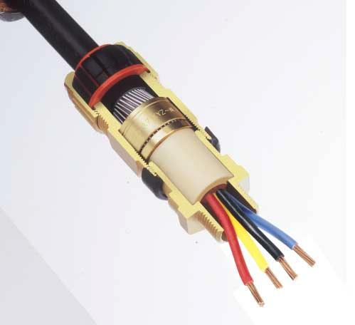
15 Entry Thread Ø 'A' Ø 'B' 5.0mm Entry Deluge Boot 'G' Approx (Compressed Length) Diaphragm Seal Armour/Braid 'C' Cable Gland Type 50/453/Universal ATEX Flameproof and Increased Safety Entry Thread CABLE GLAND SELECTION TABLE Ref. NPT* Inner Sheath 'A' Std./ Option Min. Max. Min. Os 2 ½" O A B C 2 M25 M32 ½" ¾"/½" "/¾" ¼"/" C2 M40 ½"/¼" D E F M50 M63 M75 2"/½" 2½"/2" 3"/2½" / / / Outer Sheath 'B' Larger cable glands available in 50/453 design with a compression type inner seal. G M80 3½" # # H M90 3½" # # J M00 4" # # Smaller value is applicable when selecting reduced NPT entry option. 2 s Os and O are available with an M6 thread size. For O size with M6 thread, the maximum cable inner sheath diameter is 0.9mm. # Dedicated armour clamping rings are fitted. Please specify armour type and size when ordering. Os F size metric entry threads are.5mm pitch as standard. For G size glands and above, a 2mm pitch is supplied as standard. (.5mm pitch with 5mm length of thread can be supplied) please specify when ordering. Thread length is 5mm for sizes Os to F and 20mm for sizes G to J. All dimensions in millimetres (except* where dimensions are in inches). Assembly instruction data sheet No. A.I. 300 for sizes Os to F. Assembly instruction data sheet No. A.I. 303 for sizes G to J. Cable Acceptance Details Accessories including locknuts, sealing washers, serrated washers, earth tags, shrouds, adaptors and reducers available. See pages The 50/453/Universal cable gland is manufactured in brass (standard), nickel plated brass, 36 stainless steel or aluminium. Brass NPT entries are nickel plated as standard. Max Ref. O/Os A B C C2 D E F 'C' Armour/Braid Orientation 0.9/ /.25.25/.6.6/2.0.6/2.0.8/2.5.8/2.5.8/2.5 Orientation 2 0.9/.25 0/0.7 0/0.7 0/0.7 0/0.7 0/0.7 0/0.7 0/.0 0/.0 0/.0 'G' Alternative Reversible Armour Clamping Rings (RAC) Hexagon Dimensions Across Across Flats Corners SELECTION TABLE Steel Wire Armour/Braid/Tape Orientation Orientation Application Outdoor or Indoor use. For use with single wire armoured 'W', wire braided 'X' and steel tape armoured 'Z', elastomer and plastic insulated cables. For particular use with : Cables that exhibit "Cold Flow" characteristics. See technical section of catalogue for installation rules and regulations. Features Provides armour clamping using one clamping arrangement for all armour/braid types. Provides a diaphragm seal on the cables inner sheath which will not damage cable that has "Cold Flow" characteristics. Provides an outer deluge seal to prevent moisture ingress to the cable armour/braid. Provides a cable retention and low smoke and fume, zero halogen seal onto the cables outer sheath. Flameproof Exd and Increased Safety Exe II 2 GD Baseefa 06ATEX0057X for sizes Os to F. IECEx BAS06.004X for sizes Os to F. Baseefa 06ATEX0056X for sizes G to J. IECEx BAS06.003X for sizes G to J. Suitable for use in Zone, Zone 2, Zone 2 and Zone 22. Suitable for use in Gas Groups IIA, IIBand IIC. Construction and test standards EN 5004, EN 5008, EN 5009 and EN IEC , IEC and IEC IP66, IP67 and IP68 (30 metres for 7 days) ingress protection to IEC 60529, EN and NEMA 4X. DTS0 deluge protection certified by ITS. Operating temperature range 60 C to +80 C as standard. Alternative Certification Options Available. Exd IIC/Exe II. 50/453/Universal Cable Gland Cable Gland Ordering Examples Cable Gland Type//Thread e.g. 50/453/UNIV/C/M32 50/453/UNIV/C/¼" NPT Cable Gland with Alternative Clamping Ring (AR) e.g. 50/453/UNIV/C/M32/AR 50/453/UNIV/C/¼" NPT/AR GOST RExd IICU/Exe IIU. Approved for use in Kazakhstan. AUSExd IIC/Exe II. 3
16 Entry Thread Ø 'A' Ø 'B' 5.0mm Entry 'G' Approx (Compressed Length) Armour/Braid 'C' Cable Gland Type 50/453/RAC ATEX Flameproof and Increased Safety Cable Acceptance Details Entry Thread Hexagon Inner Sheath 'A' Outer 'C' Dimensions Standard Alternative Sheath Ref. Armour/Braid 'G' NPT* Seal Seal (S) 'B' Across Across Std./ Orientation Orientation Option Min. Max. Min. Max. Min. Max. Flats Corners 2 Os 2 ½" /.25 0/ O 2 ½" /.25 0/ A ¾"/½" /.25 0/ B M25 "/¾" /.6 0/ C M32 ¼"/" /2.0 0/ C2 M40 ½"/¼" /2.0 0/ D M50 2"/½" / /2.5 0/ E M63 2½"/2" / /2.5 0/ F M75 3"/2½" / /2.5 0/ Larger cable glands available in 50/453 design. G M80 3½" # # H M90 3½" # # J M00 4" # # Smaller value is applicable when selecting reduced NPT entry option. 2s Os and O are available with an M6 thread size. For O size with M6 thread, the maximum cable inner sheath diameter is 0.9mm. 3 This cable gland type is also available for use with lead sheath cables 50/453/RAC/L. Contact Hawke sales for more information. 4Deluge protection option available. # Dedicated armour clamping rings are fitted. Please specify armour type and size when ordering. Os F size metric entry threads are.5mm pitch as standard. For G size glands and above, a 2mm pitch is supplied as standard. (.5mm pitch with 5mm length of thread can be supplied) please specify when ordering. Thread length is 5mm for sizes Os to F and 20mm for sizes G to J. All dimensions in millimetres (except* where dimensions are in inches). Assembly instruction data sheet No. A.I Accessories including locknuts, sealing washers, serrated washers, earth tags, shrouds, adaptors and reducers available. See pages The 50/453/RAC cable gland is manufactured in brass (standard), nickel plated brass, 36 stainless steel or aluminium. Brass NPT entries are nickel plated as standard. Cable Gland Ordering Examples Cable Gland Type//Thread e.g. 50/453/RAC/C/M32 50/453/RAC/C/¼" NPT Cable Gland with Alternative Seal (S) e.g. 50/453/RAC/C/M32/S 50/453/RAC/C/¼" NPT/S CABLE GLAND SELECTION TABLE Alternative Reversible Armour Clamping Rings (RAC) Ref. O/Os A B C C2 D E F SELECTION TABLE Steel Wire Armour/Braid/Tape Orientation Orientation Cable Gland with Alternative Clamping Ring (AR) e.g. 50/453/RAC/C/M32/AR 50/453/RAC/C/¼" NPT/AR Application Outdoor or Indoor use. For use with single wire armoured 'W', wire braided 'X' and steel tape armoured 'Z', elastomer and plastic insulated cables. See technical section of catalogue for installation rules and regulations. Features Provides armour clamping using one clamping arrangement for all armour/ braid types. Provides a seal on the cables inner sheath. Provides a cable retention and low smoke and fume, zero halogen seal onto the cables outer sheath. Flameproof Exd and Increased Safety Exe. II 2 GD Baseefa 06ATEX0056X. IECEx BAS06.003X. Suitable for use in Zone, Zone 2, Zone 2 and Zone 22. Suitable for use in Gas Groups IIA, IIB and IIC. Construction and test standards EN 5004, EN 5008, EN 5009 and EN IEC , IEC and IEC IP66, IP67 and IP68 (30 metres for 7 days) ingress protection to IEC 60529, EN and NEMA 4X. DTS0 deluge protection certified by ITS. Operating temperature range 60 C to +80 C as standard. Alternative Certification Options Available. Exd IIC/Exe II. GOST RExd IICU/Exe IIU. Approved for use in Kazakhstan. AUSExd IIC/Exe II. 50/453/RAC Cable Gland 4
17 Entry Thread Ø 'A' Ø 'B' 5.0mm Entry 'G' Approx (Compressed Length) Lead Sheath Bond Armour/Braid 'C' Cable Gland Type 50/453/RAC/L For Lead Sheath Cables ATEX Flameproof and Increased Safety CABLE GLAND SELECTION TABLE Cable Acceptance Details Entry Thread Hexagon Inner Lead Sheath 'A' Outer 'C' Dimensions Standard (L) Alternative Sheath Ref. (K) Seal+Bond NPT* Armour/Braid 'G' Seal+Bond 'B' Across Across Std./ Orientation Orientation Option Min. Max. Min. Max. Min. Max. Flats Corners 2 O 2 ½" /.25 0/ A ¾"/½" /.25 0/ B M25 "/¾" /.6 0/ C M32 ¼"/" /2.0 0/ C2 M40 ½"/¼" /2.0 0/ D M50 2"/½" / /2.5 0/ E M63 2½"/2" / /2.5 0/ F M75 3"/2½" / /2.5 0/ Larger cable glands available in 50/453/L design. G M80 3½" # # H M90 3½" # # J M00 4" # # s Os and O are available with an M6 thread size. For O size with M6 thread, the maximum cable inner sheath diameter is 0.9mm. 4 Deluge protection option available. # Dedicated armour clamping rings are fitted. Please specify armour type and size when ordering. Os F size metric entry threads are.5mm pitch as standard. For G size glands and above, a 2mm pitch is supplied as standard. (.5mm pitch with 5mm length of thread can be supplied) please specify when ordering. Thread length is 5mm for sizes O to F and 20mm for sizes G to J. All dimensions in millimetres (except* where dimensions are in inches). Assembly instruction data sheet No. A.I for sizes Os to F. Assembly instruction data sheet No. A.I for sizes G to J. Accessories including locknuts, sealing washers, serrated washers, earth tags, shrouds, adaptors and reducers available. See pages The 50/453/RAC/L cable gland is manufactured in brass(standard), nickel plated brass, 36 stainless steel or aluminium. Brass NPT entries are nickel plated as standard. Cable Gland Ordering Examples Cable Gland Type//Thread/ Standard Inner Seal + Bond Alternative Reversible Armour Clamping Rings (RAC) Ref. O/Os A B C C2 D E F SELECTION TABLE Steel Wire Armour/Braid/Tape Orientation Orientation Cable Gland with Alternative Clamping Ring (AR) Application Outdoor or Indoor use. For use with single wire armoured 'W' wire braided 'X' and steel tape armoured 'Z', elastomer and plastic insulated cables with a lead inner sheath. See technical section of catalogue for installation rules and regulations. Features Provides armour clamping using one clamping arrangement for all armour /braid types. Provides a seal and an electrical bond on the cables lead inner sheath. Provides a cable retention and low smoke and fume, zero halogen seal onto the cables outer sheath. Flameproof Exd and Increased Safety Exe. II 2 GD Baseefa 06ATEX0056X. IECEx BAS06.003X. Suitable for use in Zone, Zone 2, Zone 2 and Zone 22. Suitable for use in Gas Groups IIA, IIB and IIC. Construction and test standards EN 5004, EN 5008, EN 5009 and EN IEC , IEC and IEC IP66, IP67 and IP68 (30 metres for 7 days) ingress protection to IEC 60529, EN and NEMA 4X. DTS0 deluge protection certified by ITS. Operating temperature range 60 C to +80 C as standard. Alternative Certification Options Available. Exd IIC/Exe II. BRExd IIC/Exe II. 50/453/RAC/L Cable Gland e.g. 50/453/RAC/C/M32/L 50/453/RAC/C/¼" NPT/L Cable Gland with Alternative Inner Seal + Bond e.g. 50/453/RAC/C/M32/K 50/453/RAC/C/¼" NPT/K e.g. 50/453/RAC/C/M32/L/AR 50/453/RAC/C/¼" NPT/L/AR GOST RExd IICU/Exe IIU. Approved for use in Kazakhstan. 5
18 Entry Thread Ø 'B' 5.0mm Entry 'G' Approx (Compressed Length) Armour/Braid 'C' Cable Gland Type PSG 553/RAC ATEX Flameproof and Increased Safety Ref. A B C M25 M32 CABLE GLAND SELECTION TABLE Entry Thread NPT* Std./ Option ¾"/½" "/¾" ¼"/" Min. 4 Deluge protection option available. A C size metric entry threads are.5mm pitch as standard. (.5mm pitch with 5mm length of thread can be supplied) please specify when ordering. Thread length is 5mm for sizes A to C. All dimensions in millimetres (except* where dimensions are in inches). Assembly instruction data sheet No. A.I. 32. Accessories including locknuts, sealing washers, serrated washers, earth tags, shrouds, adaptors and reducers available. See pages The PSG 553/RAC cable gland is manufactured in brass (standard), nickel plated brass, 36 stainless steel or aluminium. Brass NPT entries are nickel plated as standard. Cable Gland Ordering Examples Cable Gland Type//Thread e.g. PSG 553/RAC/C/M32 PSG 553/RAC/C/¼" NPT Punch Tool Ordering Example e.g. Punch Tool Number. Cable Acceptance Details Outer Sheath 'B' Max 'C' Armour/Braid Orientation Orientation 2 0.9/.25 0/0.7.25/.6 0/0.7.6/2.0 0/0.7 'G' Hexagon Dimensions Across Flats Across Corners CABLE GLAND SIZE FOR CORE SIZE & NUMBER Cores Cross Sectional Area mm² Maximum No. of Cores Punch Ref. Core C.S.A. mm² A & B A & B B & C C B C B PUNCH TOOL SIZE DETAILS No. No.2 No Application Outdoor or Indoor use. For use with single wire armoured 'W', wire braided 'X' and steel tape armoured 'Z', elastomer and plastic insulated cables. For particular use with : a) Cables that are not effectively filled, compact and/or circular, have tape bedding or have hygroscopic fillers. b) Cables that exhibit "Cold Flow" characteristics. c) Enclosures for gas group IIC, under 2 litres in volume and containing an ignition source. d) Enclosures for gas groups IIA or IIB, which are greater than 2 litres in volume and contain an ignition source. See technical section of the catalogue for installation rules and regulations. Features Provides a barrier seal to the individual insulated cores within the cable and prevents entry of the products of an explosion into the cable. The required number of holes for the cores are punched in the seal by means of a special tool to suit the core size. Provides armour clamping using one clamping arrangement for all armour/ braid types. Provides a cable retention and low smoke and fume, zero halogen seal onto the cables outer sheath. Flameproof Exd and Increased Safety Exe. II 2 GD Baseefa 06ATEX0056X. IECEx BAS06.003X. Suitable for use in Zone, Zone 2, Zone 2 and Zone 22. Suitable for use in Gas Groups IIA, IIB and IIC. Construction and test standards EN 5004, EN 5008, EN 5009 and EN IEC , IEC and IEC IP66, IP67 and IP68 (30 metres for 7 days) ingress protection to IEC and EN Operating temperature range 60 C to +80 C as standard. PSG 553/RAC Cable Gland 6
19 Entry Thread Ø 'E' Ø 'D' Ø 'B' 5.0mm Entry 'G' Approx (Compressed Length) Inspectable Compound Cable Gland Type ICG 623 ATEX Flameproof and Increased Safety Os F size metric entry threads are.5mm pitch as standard. (.5mm pitch with 5mm length of thread can be supplied) please specify when ordering. Thread length is 5mm for sizes Os to F. All dimensions in millimetres (except* where dimensions are in inches). Two part sealing compound and assembly instructions are supplied with the cable gland. Assembly instruction data sheet No. A.I Accessories including locknuts, sealing washers, serrated washers, earth tags, shrouds, adaptors and reducers available. See pages The ICG 623 cable gland is manufactured in brass(standard), nickel plated brass, 36 stainless steel or aluminium. Brass NPT entries are nickel plated as standard. Cable Gland Ordering Examples Cable Gland Type//Thread e.g. ICG 623/C/M32 ICG 623/C/¼" NPT Cable Gland with Alternative Seal (S) e.g. ICG 623/C/M32/S ICG 623/C/¼" NPT/S CABLE GLAND SELECTION TABLE Cable Acceptance Details Entry Thread Hexagon Inner Sheath/ Outer Sheath 'B' Dimensions Cores Standard Alternative Ref. 'G' NPT* 'D' 'E' Max. Max. Seal Max. No. Seal (S) Across Across Std./ Over Inner Of Option Min. Max. Cores Sheath Cores Min. Max. Flats Corners Os ½" O ½" A ¾"/½" B M25 "/¾" C M32 ¼"/" C2 M40 ½"/¼" D M50 2"/½" E M63 2½"/2" F M75 3"/2½" / Smaller value is applicable when selecting reduced NPT entry option. Application Outdoor or Indoor use. For use with nonarmoured elastomer and plastic insulated cables. For particular use with : a) Cables that are not effectively filled, compact and/or circular, have tape bedding or have hygroscopic fillers. b) Cables that exhibit "Cold Flow" characteristics. c) Enclosures containing an ignition source in gas group II C areas or containing an ignition source in a Zone area and exceeding 2 litres in volume. See technical section of the catalogue for installation rules and regulations. Features Provides a barrier seal between the individual insulated cores within the cable and prevents entry of the products of an explosion into the cable. Assembly of the cable gland compresses and distributes the compound evenly to create a barrier seal at the point of entry into the enclosure. The compound chamber may be seperated from the cured compound to ensure that the chamber has been effectively filled. If required, external voids can be repaired. Provides a cable retention seal onto the cables outer sheath. Flameproof Exd and Increased Safety Exe. II 2 GD Baseefa 06ATEX0058X. IECEx BAS06.005X. Suitable for use in Zone, Zone 2, Zone 2 and Zone 22. Suitable for use in Gas Groups IIA, IIB and IIC. Construction and test standards EN 5004, EN 5008, EN 5009 and EN IEC , IEC and IEC IP66, IP67 and IP68 (30 metres for 7 days) ingress protection to IEC 60529, EN and NEMA 4X. DTS0 deluge protection certified by ITS. Operating temperature range 60 C to +80 C as standard. Alternative Certification Options Available. Exd IIC/Exe II. BRExd IIC/Exe II. AUSExd IIC/Exe II. ICG 623 Cable Gland 7
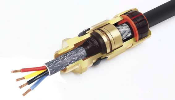
20 Entry Thread Ø 'E' Ø 'D' Ø 'B' 5.0mm Entry Inspectable Compound 'G' Approx (Compressed Length) Deluge Boot Armour/Braid 'C' Cable Gland Type ICG 653/Universal ATEX Flameproof and Increased Safety CABLE GLAND SELECTION TABLE Cable Acceptance Details Entry Thread Inner Sheath/ Outer 'C' Cores Sheath Ref. Armour/Braid 'G' NPT* 'D' 'E' Max. 'B' Max. Max. No. Across Std./ Over Inner Of Orientation Orientation Option Min. Max. Flats Cores Sheath Cores 2 Os ½" /.25 0/ O ½" /.25 0/ A ¾"/½" /.25 0/ B M25 "/¾" /.6 0/ C M32 ¼"/" /2.0 0/ C2 M40 ½"/¼" /2.0 0/ D M50 2"/½" /2.5 0/ E M63 2½"/2" /2.5 0/ F M75 3"/2½" / /2.5 0/ Smaller value is applicable when selecting reduced NPT entry option. Os F size metric entry threads are.5mm pitch as standard. (.5mm pitch with 5mm length of thread can be supplied) please specify when ordering. Thread length is 5mm for sizes Os to F. All dimensions in millimetres (except* where dimensions are in inches). Two part sealing compound and assembly instructions are supplied with the cable gland. Assembly instruction data sheet No. A.I. 30. Accessories including locknuts, sealing washers, serrated washers, earth tags, shrouds, adaptors and reducers available. See pages The ICG 653/Universal cable gland is manufactured in brass (standard), nickel plated brass, 36 stainless steel or aluminium. Brass NPT entries are nickel plated as standard. Cable Gland Ordering Examples Cable Gland Type//Thread e.g. ICG 653/UNIV/C/M32 ICG 653/UNIV/C/¼" NPT Cable Gland with Alternative Clamping Ring (AR) e.g. ICG 653/UNIV/C/M32/AR ICG 653/UNIV/C/¼" NPT/AR Alternative Reversible Armour Clamping Rings (RAC) Ref. O/Os A B C C2 D E F Hexagon Dimensions Across Corners SELECTION TABLE Steel Wire Armour/Braid/Tape Orientation Orientation Application Outdoor or Indoor use. For use with single wire armoured 'W', wire braided 'X' and steel tape armoured 'Z', elastomer and plastic insulated cables. For particular use with : a) Cables that are not effectively filled, compact and/or circular, have tape bedding or have hygroscopic fillers. b) Cables that exhibit "Cold Flow" characteristics. c) Enclosures containing an ignition source in gas group II C areas or containing an ignition source in a Zone area. See technical section of the catalogue for installation rules and regulations. Features Provides a barrier seal between the individual insulated cores within the cable and prevents entry of the products of an explosion into the cable. Assembly of the cable gland compresses and distributes the compound evenly to create a barrier seal at the point of entry into the enclosure. The compound chamber may be seperated from the cured compound to ensure that the chamber has been effectively filled. If required, external voids can be repaired. Provides armour clamping, using one clamping arrangement for all armour/braid types. Provides an outer deluge seal to prevent moisture ingress to the cable armour/braid. Provides a cable retention and low smoke and fume, zero halogen seal onto the cables outer sheath. Flameproof Exd and Increased Safety Exe. II 2 GD Baseefa 06ATEX0058X. IECEx BAS06.005X. Suitable for use in Zone, Zone 2, Zone 2 and Zone 22. Suitable for use in Gas Groups IIA, IIB and IIC. Construction and test standards EN 5004, EN 5008, EN 5009 and EN IEC , IEC and IEC IP66, IP67 and IP68 (30 metres for 7 days) ingress protection to IEC 60529, EN and NEMA 4X. DTS0 deluge protection certified by ITS. Operating temperature range 60 C to +80 C as standard. Alternative Certification Options Available. Exd IIC/Exe II. BRExd IIC/Exe II. GOST RExd IICU/Exe IIU. AUSExd IIC/Exe II. ICG 653/Universal Cable Gland 8
21 Entry Thread Ø 'E' Ø 'D' Ø 'B' 5.0mm Entry Inspectable Compound 'G' Approx (Compressed Length) Deluge Boot Lead Sheath Bond Armour/Braid 'C' Cable Gland Type ICG 653/Universal/L For Lead Sheath Cables ATEX Flameproof and Increased Safety Ref. Os O A B C C2 D E F CABLE GLAND SELECTION TABLE Cable Acceptance Details Entry Thread Hexagon Inner Sheath/ Outer 'C' Dimensions Cores Sheath Armour/Braid 'G' NPT* 'D' 'E' Max. 'B' Max. Min. Max. No. Across Across Std./ Over Inner Inner Of Orientation Orientation Option Min. Max. Flats Corners Cores Sheath Sheath Cores 2 ½" /.25 0/ ½" /.25 0/ ¾"/½" /.25 0/ M25 M32 "/¾" ¼"/" / /2.0 0/0.7 0/ M40 ½"/¼" /2.0 0/ M50 2"/½" /2.5 0/ M63 M75 2½"/2" 3"/2½" /2.5.8/2.5 0/.0 0/ Os F size metric entry threads are.5mm pitch as standard. (.5mm pitch with 5mm length of thread can be supplied) please specify when ordering. Thread length is 5mm for sizes Os to F. All dimensions in millimetres (except* where dimensions are in inches). Two part sealing compound and assembly instructions are supplied with the cable gland. Assembly instruction data sheet No. A.I Accessories including locknuts, sealing washers, serrated washers, earth tags, shrouds, adaptors and reducers available. See pages The ICG 653/Universal/L cable gland is manufactured in brass (standard), nickel plated brass, 36 stainless steel or aluminium. Brass NPT entries are nickel plated as standard. Cable Gland Ordering Examples Cable Gland Type//Thread/Bond e.g. ICG 653/UNIV/C/M32/L ICG 653/UNIV/C/¼" NPT/L Cable Gland with Alternative Clamping Ring (AR) e.g. ICG 653/UNIV/C/M32/L/AR ICG 653/UNIV/C/¼" NPT/L/AR Alternative Reversible Armour Clamping Rings (RAC) Ref. O/Os A B C C2 D E F SELECTION TABLE Steel Wire Armour/Braid/Tape Orientation Orientation Application Outdoor or Indoor use. For use with single wire armoured 'W', wire braided 'X' and steel tape armoured 'Z', elastomer and plastic insulated cables with a lead inner sheath. For particular use with : a) Cables that are not effectively filled, compact and/or circular, have tape bedding or have hygroscopic fillers. b) Cables that exhibit "Cold Flow" characteristics. c) Enclosures containing an ignition source in gas group II C areas or containing an ignition source in a Zone area. See technical section of the catalogue for installation rules and regulations. Features Provides a barrier seal between the individual insulated cores within the cable and prevents entry of the products of an explosion into the cable. Assembly of the cable gland compresses and distributes the compound evenly to create a barrier seal at the point of entry into the enclosure. The compound chamber may be seperated from the cured compound to ensure that the chamber has been effectively filled. If required, external voids can be repaired. Provides armour clamping, using one clamping arrangement for all armour/braid types. Provides a seal and an electrical bond on the cables lead inner sheath. Provides an outer deluge seal to prevent moisture ingress to the cable armour/braid. Provides a cable retention and low smoke and fume, zero halogen seal onto the cables outer sheath. Flameproof Exd and Increased Safety Exe. II 2 GD Baseefa 06ATEX0058X. IECEx BAS06.005X. Suitable for use in Zone, Zone 2, Zone 2 and Zone 22. Suitable for use in Gas Groups IIA, IIB and IIC. Construction and test standards EN 5004, EN 5008, EN 5009 and EN IEC , IEC and IEC IP66, IP67 and IP68 (30 metres for 7 days) ingress protection to IEC 60529, EN and NEMA 4X. DTS0 deluge protection certified by ITS. Operating temperature range 60 C to +80 C as standard. Alternative Certification Options Available. Exd IIC/Exe II. BRExd IIC/Exe II. GOST RExd IICU/Exe IIU. ICG 653/Universal/L Cable Gland 9
22 Male Entry Thread Ø 'B' Female Entry Thread 5.0mm Entry 'G' Approx (Compressed Length) Cable Gland Type 50/44 ATEX Flameproof and Increased Safety Ref. Os O A B C 2 M25 M32 CABLE GLAND SELECTION TABLE Male Entry Thread 2 NPT* Std./ Option ½" ½" ¾"/½" "/¾" ¼"/" Female Entry Thread NPT # M25 M32 Smaller value is applicable when selecting reduced NPT entry option. 2 s Os and O are available with an M6 thread size. For O size with M6 thread, the maximum cable inner sheath diameter is 0.9mm. # NPT female thread sizes equivalent to those shown in the table for the male thread size are available. Hexagon dimensions as shown may alter. Os C size metric entry threads are.5mm pitch as standard. (.5mm pitch with 5mm length of thread can be supplied) please specify when ordering. Thread length is 5mm for sizes Os to C. All dimensions in millimetres (except* where dimensions are in inches). Assembly instruction data sheet No. A.I. 30. Accessories including locknuts, sealing washers, serrated washers, earth tags, shrouds, adaptors and reducers available. See pages The 50/44 cable gland is manufactured in brass(standard), nickel plated brass, 36 stainless steel or aluminium. Brass NPT entries are nickel plated as standard. Cable Gland Ordering Examples Cable Gland Type//MaleThread/ Female Thread e.g. 50/44/C/M32/M32 50/44/C/¼" NPT/M32 Cable Gland with Alternative Seal (S) e.g. 50/44/C/M32/M32/S 50/44/C/¼" NPT/M32/S Cable Acceptance Details Outer Sheath 'B' Standard Alternative Seal Seal (S) Min. Max. Min. Max 'G' Hexagon Dimensions Across Flats Across Corners Application Outdoor or Indoor use. For use with nonarmoured elastomer and plastic insulated cables installed in conduit. See technical section of the catalogue for installation rules and regulations. Features Provides a cable retention seal onto the cables outer sheath. When used in increased safety applications, this cable gland may be used with braided cable where the braid and the cables outer sheath pass into the enclosure. The braid must be suitably terminated into the enclosure. Provides female running coupler for cable gland or conduit entry. Flameproof Exd and Increased Safety Exe. II 2 GD Baseefa 06ATEX0056X. IECEx BAS06.003X. Suitable for use in Zone, Zone 2, Zone 2 and Zone 22. Suitable for use in Gas Groups IIA, IIB and IIC. Construction and test standards EN 5004, EN 5008, EN 5009 and EN IEC , IEC and IEC IP66, IP67 and IP68 (30 metres for 7 days) ingress protection to IEC and EN DTS0 deluge protection certified by ITS. Operating temperature range 60 C to +00 C as standard. Alternative Certification Options Available. Exd IIC/Exe II. 50/44 Cable Gland 20
23 Male Entry Thread Female Entry Thread 5.0mm Entry 'G' Approx (Compressed Length) Cable Gland Type SB 474 ATEX Flameproof and Increased Safety Ref. A B C CABLE GLAND SELECTION TABLE Male Entry Thread M25 M32 NPT* Std./ Option ¾"/½" "/¾" ¼"/" # NPT female thread sizes equivalent to those shown in the table for the male thread size are available. Hexagon dimensions as shown may alter. A C size metric entry threads are.5mm pitch as standard. (.5mm pitch with 5mm length of thread can be supplied) please specify when ordering. Thread length is 5mm for sizes A to C. All dimensions in millimetres (except* where dimensions are in inches). Assembly instruction data sheet No. A.I Accessories including locknuts, sealing washers, serrated washers, earth tags, shrouds, adaptors and reducers available. See pages The SB 474 cable gland is manufactured in brass (standard), nickel plated brass, 36 stainless steel or aluminium. Brass NPT entries are nickel plated as standard. Cable Gland Ordering Examples Cable Gland Type//Male Thread/Female Thread e.g. SB 474/C/M32/M32 SB 474/C/¼" NPT/M32 Punch Tool Ordering Example e.g. Punch Tool Number. Female Entry Thread M25 M32 NPT # Hexagon Dimensions Across Flats Across Corners CABLE GLAND SIZE FOR CORE SIZE & NUMBER Cores Cross Sectional Area mm² Maximum No. of Cores Punch Ref. Core C.S.A. mm² A & B A & B B & C C B C B PUNCH TOOL SIZE DETAILS No. No.2 No 'G' Application Outdoor or Indoor use. For particular use with : a) Cables that are not effectively filled, compact and/or circular, have tape bedding or have hygroscopic fillers. b) Cables that exhibit "Cold Flow" characteristics. c) Enclosures for gas group IIC, under 2 litres in volume and containing an ignition d) Enclosures for gas groups IIA or IIB, which are greater than 2 litres in volume and contain an ignition source. See technical section of the catalogue for installation rules and regulations. Features Provides a barrier seal to the individual insulated cores within the cable and prevents entry of the products of an explosion into the cable. The required number of holes for the cores are punched in the seal by means of a special tool to suit the core size. DTS0 deluge protection certified by ITS. Provides female running coupler for cable gland or conduit entry. Flameproof Exd and Increased Safety Exe. II 2 GD Baseefa 06ATEX0056X. IECEx BAS06.003X. Suitable for use in Zone, Zone 2, Zone 2 and Zone 22. Suitable for use in Gas Groups IIA, IIB and IIC. Construction and test standards EN 5004, EN 5008, EN 5009 and EN IEC , IEC and IEC IP66, IP67 and IP68 (30 metres for 7 days) ingress protection to IEC and EN Operating temperature range 60 C to +80 C as standard. Alternative Certification Options Available. SB 474 Cable Gland 2
24 Male Entry Thread Ø 'E' Ø 'D' Female Entry Thread 5.0mm Entry 'G' Approx (Compressed Length) Inspectable Compound Allen Grub Screw 2mm A/F AC 2.5mm A/F C2F Cable Gland Type CSB 656 ATEX Flameproof and Increased Safety Ref. A B C C2 D E F M25 M32 M40 M50 M63 M75 CABLE GLAND SELECTION TABLE Male Entry Thread NPT* Std./ Option ¾"/½" "/¾" ¼"/" ½"/¼" 2"/½" 2½"/2" 3"/2½" # NPT female thread sizes equivalent to those shown in the table for the male thread size are available. Hexagon dimensions as shown may alter. A F size metric entry threads are.5mm pitch as standard. Thread length is 5mm for sizes Os to F. All dimensions in millimetres (except* where dimensions are in inches). Two part sealing compound and assembly instructions are supplied with the cable gland. Assembly instruction data sheet No. A.I. 3. Accessories including locknuts, sealing washers, serrated washers, earth tags, shrouds, adaptors and reducers available. See pages The CSB 656 cable gland is manufactured in brass(standard), nickel plated brass, 36 stainless steel or aluminium. Brass NPT entries are nickel plated as standard. Cable Gland Ordering Examples Cable Gland Type//Male Thread/Female Thread e.g. CSB 656/C/M32/M32 CSB 656/C/¼" NPT/M32 Alternative Certification Options Available. Exd IIC/Exe II. AUSExd IIC/Exe II. Female Entry Thread M25 M32 M40 M50 M63 M75 NPT # Inner Sheath/ Cores 'D' Max. Over Cores 'E' Max. Inner Sheath Max. No. Of Cores 'G' Hexagon Dimensions Across Flats Across Corners Application Outdoor or Indoor use. For use with conduit incorporating individual insulated conductors or For particular use with : a) Cables that are not effectively filled, compact and/or circular, have tape bedding or have hygroscopic fillers. b) Cables that exhibit "Cold Flow" characteristics. c) Enclosures containing an ignition source in gas group II C areas or containing an ignition source in a Zone area and exceeding 2 litres in volume. See technical section of the catalogue for installation rules and regulations. Features Provides a barrier seal between the individual insulated cores within the cable and prevents entry of the products of an explosion into the cable or conduit. Seals conductors at entry to enclosure via conduit or enables an existing cable gland to be converted to a barrier type cable gland. The device is fitted with a simple compound filled chamber which permits packing around individual insulated conductors. Assembly of the cable gland compresses and distributes the compound evenly to create a barrier seal at the point of entry into the enclosure. The compound chamber may be seperated from the cured compound to ensure that the chamber has been effectively filled. If required, external voids can be repaired. Provides female running coupler for cable gland or conduit entry. CSB 656 Cable Gland Flameproof Exd and Increased Safety Exe. II 2 GD Baseefa 06ATEX0058X. IECEx BAS06.005X. Suitable for use in Zone, Zone 2, Zone 2 and Zone 22. Suitable for use in Gas Groups IIA, IIB and IIC. Construction and test standards EN 5004, EN 5008, EN 5009 and EN IEC , IEC and IEC IP66, IP67 and IP68 (30 metres for 7 days) ingress protection to IEC 60529, EN and NEMA 4X. DTS0 deluge protection certified by ITS. Operating temperature range 60 C to +80 C as standard. 22
 Armour/Braid 'C' 'G' Approx (Compressed Length) Armour/Braid 'C' 50/453 Assembly instruction data sheet No. A.I. 303.")
. 5 Assembly instruction data sheet No. A.I. 34.")
25 Entry Thread Ø 'B' Entry Thread Ø 'A' Ø 'B' Entry Thread Ø 'A' Ø 'B' Entry Thread Ø 'A' Ø 'B' Oversize, G, H & J Cable Glands ATEX Flameproof/Increased Safety and Industrial 50/453 Flameproof / Increased Safety 5.0mm Entry 5 Industrial 5.0mm Entry 'G' Approx (Compressed Length) Armour/Braid 'C' 'G' Approx (Compressed Length) Armour/Braid 'C' 50/453 Assembly instruction data sheet No. A.I For application, features, technical data, general information, materials/finishes and cable gland ordering examples, please refer to : Page 3 (50/453/Universal). Page 4 (50/453/RAC). Page 5 (50/453/RAC/L). 5 Assembly instruction data sheet No. A.I. 34. For application, features, technical data, general information, materials/finishes and cable gland ordering examples, please refer to : Page 42 (I5/RAC). Oversize G, H and J Cable Glands 53 Industrial 5.0mm Entry 'G' Approx (Compressed Length) Armour/Braid 'C' 53 Assembly instruction data sheet No. A.I For application, features, technical data, general information, materials/finishes and cable gland ordering examples, please refer to : Page 39 (I53/RAC). Page 40 (53/RAC/L). American Series Cable Glands 'H' (M90) cable glands are available with the exception of the 755. Please contact Hawke for details. 32 Increased Safety 5.0mm Entry 'G' Approx~ ~(Compressed Length) The 32cable gland is manufactured in brass (standard), nickel plated brass, 36 stainless steel or aluminium. Brass NPT entries are nickel plated as standard. All of Hawke's Hazardous Area cable glands are dual certified (i.e. Flameproof and Increased Safety). The following cable glands are also available to Increased Safety certification only. 32 Assembly instruction data sheet No. A.I For sizes O s to J. Baseefa Certificate No. BAS 0 ATEX 2266X. For application, features, technical data, general information, materials/finishes and cable gland ordering examples, please refer to : Page (50/42). Increased Safety Cable Glands 23
26 Entry Thread Ø 'B' 'H' Entry 'G' Approx(Compressed Length) Cable Gland Type HPGEx Thread ATEX Increased Safety Entry Thread M2 M2 M6 M6 M6 M6 M25 M25 M32 M32 M40 M40 M50 M50 M63 M63 Thread Length 'H' Cable Acceptance Details Outer Sheath 'B' Min. Max CABLE GLAND SELECTION TABLE 'G' Product Part Codes Black Blue Grey P3/M2//S/S/A P3/M2//S/B/A P3/M2/2/S/S/A P3/M2/2/S/B/A P3/M6//S/S/A P3/M6//S/B/A P3/M6/2/S/S/A P3/M6/2/S/B/A P3/M6/3/S/S/A P3/M6/3/S/B/A P3/M6/4/S/S/A P3/M6/4/S/B/A P3///S/S/A P3///S/B/A P3//2/S/S/A P3//2/S/B/A P3//3/S/S/A P3//3/S/B/A P3//4/S/S/A P3//4/S/B/A P3/M25//S/S/A P3/M25//S/B/A P3/M25/2/S/S/A P3/M25/2/S/B/A P3/M32//S/S/A P3/M32//S/B/A P3/M32/2/S/S/A P3/M32/2/S/B/A P3/M40//S/S/A P3/M40//S/B/A P3/M40/2/S/S/A P3/M40/2/S/B/A P3/M50//S/S/A P3/M50//S/B/A P3/M50/2/S/S/A P3/M50/2/S/B/A P3/M63//S/S/A P3/M63//S/B/A P3/M63/2/S/S/A P3/M63/2/S/B/A P3/M2//S/G/A P3/M2/2/S/G/A P3/M6//S/G/A P3/M6/2/S/G/A P3/M6/3/S/G/A P3/M6/4/S/G/A P3///S/G/A P3//2/S/G/A P3//3/S/G/A P3//4/S/G/A P3/M25//S/G/A P3/M25/2/S/G/A P3/M32//S/G/A P3/M32/2/S/G/A P3/M40//S/G/A P3/M40/2/S/G/A P3/M50//S/G/A P3/M50/2/S/G/A P3/M63//S/G/A P3/M63/2/S/G/A HPGEx Cable Gland All entry threads are.5mm pitch as standard. All dimensions in millimetres. Also available in NPT and PG threads. Assembly instruction data sheet No. A.I Accessories including locknuts, sealing washers, serrated washers, earth tags, shrouds, adaptors and reducers available. See pages The body of the gland is manufactured in polyamide. The gasket and O ring are manufactured in NBR (NitrileButadiene Rubber). Cable Gland Ordering Examples For ordering examples please see product part codes section in the selection table above. Application Outdoor or Indoor use. For use with nonarmoured elastomer and plastic insulated cables. See technical section of the catalogue for installation rules and regulations. Features Provides a cable seal onto the cables outer sheath. Two piece gland. Captive cable seal. Vibration resistant back nut/clamp. UL94VO rated. Increased Safety Exe. II 2G D Ex eii td A20. BVS 06 ATEX E 54X. Suitable for use in Zone, Zone 2, Zone 20, Zone 2 and Zone 22. Suitable for use in Gas Groups IIA, IIB and IIC. IP66, IP67 and IP68 (up to 0 bar with O ring) ingress protection. Operating temperature range 20 C to +90 C as standard. 24
27 Entry Thread Ø 'B' 'H' PG Entry 'G' Approx(Compressed Length) Cable Gland Type HPGEx NPT Thread ATEX Increased Safety Entry Thread NPT * /2 /2 /2 /6 /2 /6 3/4 3/4 /4 /4 /2 /2 Thread Length 'H' 3/ / Cable Acceptance Details Outer Sheath 'B' 'G' Product Part Codes Min. Max. Black Blue Grey P3/M3/8 NPT//S/A P3/M3/8 NPT//B/A P3/M3/8 NPT/2/S/A P3/M3/8 NPT/2/B/A P3/M/2 NPT//S/A P3/M/2 NPT//B/A P3/M/2 NPT/2/S/A P3/M/2 NPT/2/B/A P3/M/2 NPT(6)//S/A P3/M/2 NPT(6)//B/A P3/M/2 NPT(6)/2/S/A P3/M/2 NPT(6)/2/B/A P3/M3/4 NPT//S/A P3/M3/4 NPT//B/A CABLE GLAND SELECTION TABLE P3/M3/4 NPT/2/S/A P3/M NPT//S/A P3/M NPT/2/S/A P3/M /4 NPT//S/A P3/M /4 NPT/2/S/A P3/M /2 NPT//S/A P3/M /2 NPT/2/S/A P3/M3/4 NPT/2/B/A P3/M NPT//B/A P3/M NPT/2/B/A P3/M /4 NPT//B/A P3/M /4 NPT/2/B/A P3/M /2 NPT//B/A P3/M /2 NPT/2/B/A P3/M3/8 NPT//G/A P3/M3/8 NPT/2/G/A P3/M/2 NPT//G/A P3/M/2 NPT/2/G/A P3/M/2 NPT(6)//G/A P3/M/2 NPT(6)/2/G/A P3/M3/4 NPT//G/A P3/M3/4 NPT/2/G/A P3/M NPT//G/A P3/M NPT/2/G/A P3/M /4 NPT//G/A P3/M /4 NPT/2/G/A P3/M /2 NPT//G/A P3/M /2 NPT/2/G/A HPGEx Cable Gland NPT All dimensions in millimetres (except* where dimensions are in inches). Also available in and PG threads. Assembly instruction data sheet No. A.I Accessories including locknuts, sealing washers, serrated washers, earth tags, shrouds, adaptors and reducers available. See pages The body of the gland is manufactured in polyamide. The gasket and O ring are manufactured in NBR (NitrileButadiene Rubber). Cable Gland Ordering Examples For ordering examples please see product part codes section in the selection table above. Application Outdoor or Indoor use. For use with nonarmoured elastomer and plastic insulated cables. See technical section of the catalogue for installation rules and regulations. Features Provides a cable seal onto the cables outer sheath. Two piece gland. Captive cable seal. Vibration resistant back nut/clamp. UL94VO rated. Increased Safety Exe. II 2G D Ex eii td A20. BVS 06 ATEX E 54X. Suitable for use in Zone, Zone 2, Zone 20, Zone 2 and Zone 22. Suitable for use in Gas Groups IIA, IIB and IIC. IP66, IP67 and IP68 (up to 0 bar with O ring) ingress protection. Operating temperature range 20 C to +90 C as standard. 25
28 Entry Thread Ø 'B' 'H' PG Entry 'G' Approx(Compressed Length) Cable Gland Type HPGEx PG Thread ATEX Increased Safety Thread Cable Acceptance Details Length Outer Sheath 'B' 'G' Product Part Codes 'H' Min. Max. Black Blue Grey P3/PG7//S/S/A P3/PG7//S/B/A P3/PG7/2/S/S/A P3/PG7/2/S/B/A P3/PG9//S/S/A P3/PG9//S/B/A P3/PG9/2/S/S/A P3/PG9/2/S/B/A P3/PG/3/S/S/A P3/PG/3/S/B/A P3/PG/4/S/S/A P3/PG/4/S/B/A P3/PG3.5//S/S/A P3/PG3.5//S/B/A Entry Thread PG CABLE GLAND SELECTION TABLE P3/PG3.5/2/S/S/A P3/PG6/3/S/S/A P3/PG6/4/S/S/A P3/PG2//S/S/A P3/PG2/2/S/S/A P3/PG29//S/S/A P3/PG29/2/S/S/A P3/PG36//S/S/A P3/PG36/2/S/S/A P3/PG42//S/S/A P3/PG42/2/S/S/A P3/PG48//S/S/A P3/PG48/2/S/S/A P3/PG3.5/2/S/B/A P3/PG6/3/S/B/A P3/PG6/4/S/B/A P3/PG2//S/B/A P3/PG2/2/S/B/A P3/PG29//S/B/A P3/PG29/2/S/B/A P3/PG36//S/B/A P3/PG36/2/S/B/A P3/PG42//S/B/A P3/PG42/2/S/B/A P3/PG48//S/B/A P3/PG48/2/S/B/A P3/M2//S/G/A P3/M2/2/S/G/A P3/M6//S/G/A P3/M6/2/S/G/A P3/M6/3/S/G/A P3/M6/4/S/G/A P3///S/G/A P3//2/S/G/A P3//3/S/G/A P3//4/S/G/A P3/M25//S/G/A P3/M25/2/S/G/A P3/M32//S/G/A P3/M32/2/S/G/A P3/M40//S/G/A P3/M40/2/S/G/A P3/M50//S/G/A P3/M50/2/S/G/A P3/M63//S/G/A P3/M63/2/S/G/A HPGEx Cable Gland PG All dimensions in millimetres. Also available in and NPT threads. Assembly instruction data sheet No. A.I Accessories including locknuts, sealing washers, serrated washers, earth tags, shrouds, adaptors and reducers available. See pages The body of the gland is manufactured in polyamide. The gasket and O ring are manufactured in NBR (NitrileButadiene Rubber). Cable Gland Ordering Examples For ordering examples please see product part codes section in the selection table above. Application Outdoor or Indoor use. For use with nonarmoured elastomer and plastic insulated cables. See technical section of the catalogue for installation rules and regulations. Features Provides a cable seal onto the cables outer sheath. Two piece gland. Captive cable seal. Vibration resistant back nut/clamp. UL94VO rated. Increased Safety Exe. II 2G D Ex eii td A20. BVS 06 ATEX E 54X. Suitable for use in Zone, Zone 2, Zone 20, Zone 2 and Zone 22. Suitable for use in Gas Groups IIA, IIB and IIC. IP66, IP67 and IP68 (up to 0 bar with O ring) ingress protection. Operating temperature range 20 C to +90 C as standard. 26
29 Plastic Cable Gland Accessories Nylon Locknuts x.5mm Pitch 'X' NPT Nylon Locknuts 'X' 'Z' 'Z' Cable Gland M2 M6 M25 M32 M40 M50 M63 NPT * Cable Gland 3/8 /2 3/4 LOCKNUT SELECTION TABLE Across Flats 'X' Across Flats 'X' 'Z' 'Z' Black P3/LN/M2/S P3/LN/M6/S P3/LN//S P3/LN/M25/S P3/LN/M32/S P3/LN/M40/S P3/LN/M50/S P3/LN/M63/S Black Product Part Codes LOCKNUT SELECTION TABLE P3/LN/3/8 NPT/S P3/LN/2 NPT/S P3/LN/3/4 NPT/S P3/LN/ NPT/S Grey P3/LN/M2/G P3/LN/M6/G P3/LN//G P3/LN/M25/G P3/LN/M32/G P3/LN/M40/G P3/LN/M50/G P3/LN/M63/G Product Part Codes Grey P3/LN/3/8 NPT/G P3/LN//2 NPT/G P3/LN/3/4 NPT/G P3/LN/ NPT/G Plastic Cable Gland Accessories PG Nylon Locknuts 'X' 'Z' PG Cable Gland PG7 PG9 PG PG3.5 PG6 PG2 PG29 PG36 PG42 PG48 LOCKNUT SELECTION TABLE Across Flats 'X' 'Z' Black P3/LN/PG7/S P3/LN/PG9/S P3/LN/PG/S P3/LN/PG3.5/S P3/LN/PG6/S P3/LN/PG2/S P3/LN/PG29/S P3/LN/PG36/S P3/LN/PG42/S P3/LN/PG48/S Product Part Codes Grey P3/LN/PG7/G P3/LN/PG9/G P3/LN/PG/G P3/LN/PG3.5/G P3/LN/PG6/G P3/LN/PG2/G P3/LN/PG29/G P3/LN/PG36/G P3/LN/PG42/G P3/LN/PG48/G Features Secures a cable gland in position at the equipment. Operating temperature range 20 C to +90 C as standard. The locknut is manufactured in polyamide. All dimensions in millimetres (except* where dimensions are in inches). Hawke does not recommend the use of tapered entry threads in enclosures with plain clearance holes. Parallel threaded entries are recommended for this purpose. Ordering Example For ordering examples please see product part codes section in the selection tables above. 27


30 ATEX Cable Glands Group Mining Flameproof and Increased Safety SAFETY THROUGH INSPECTABILITY Features of Hawke's Mining Gland Range Include: Unique Rear Sealing System Wide Cable Acceptance Range This arrangement offers IP66, IP67, IP68, NEMA 4X and Deluge (DTS0) Ingress Protection. The seal is manufactured from a silicone material, has LSFZH properties, is ozone and oil resistant and is suitable for use at both high and low temperatures. The Rear Sealing System covers the entire range of cable diameters without the need for special seals and the cable acceptance range is stamped on the backnut for ease of inspection. The backnut can be hand tightened, with only one further spanner turn required to ensure IP66, IP67 and NEMA 4X. Group Cable Glands Unique Inspectable Compound Chamber Designed for Safety The revolutionary Hawke compound chamber has been designed with inspectability in mind. The prelubricated compound chamber can be removed once the compound has fully cured, allowing full inspection of the flameproof seal. If required minor surface voids can be repaired in situ. This unique patented compound chamber now forms the compound as well as providing a flameproof seal, resulting in reduced piece parts, as there is no longer a requirement for a separate seal and compound chamber. Hawke "Leading the way in the design of worldwide connection solutions" 28
31 Entry Thread Ø 'E' Ø 'D' Ø 'B' 5.0mm Entry Inspectable Compound 'G' Approx (Compressed Length) Armour/Braid 'C' Group Cable Gland 653/Universal ATEX Mining Flameproof and Increased Safety CABLE GLAND SELECTION TABLE Cable Acceptance Details Entry Thread Inner Sheath/ Outer 'C' Cores Sheath Ref. Armour/Braid 'G' NPT* 'D' 'E' Max. 'B' Max. Max. No. Across Std./ Over Inner Of Orientation Orientation Option Min. Max. Flats Cores Sheath Cores 2 Os ½" /.25 0/ O ½" /.25 0/ A ¾"/½" /.25 0/ B M25 "/¾" /.6 0/ C M32 ¼"/" /2.0 0/ C2 M40 ½"/¼" /2.0 0/ D M50 2"/½" /2.5 0/ E M63 2½"/2" /2.5 0/ F M75 3"/2½" / /2.5 0/ Smaller value is applicable when selecting reduced NPT entry option. Os F size metric entry threads are.5mm pitch as standard. (.5mm pitch with 5mm length of thread can be supplied) please specify when ordering. Thread length is 5mm for sizes Os to F. All dimensions in millimetres (except* where dimensions are in inches). Two part sealing compound and assembly instructions are supplied with the cable gland. Assembly instruction data sheet No. A.I. 30. Accessories including locknuts, sealing washers, serrated washers, earth tags, shrouds, adaptors and reducers available. See pages The ICG 653/Universal is manufactured in brass (standard), nickel plated brass, 36 stainless steel or aluminium. Brass NPT entries are nickel plated as standard. Cable Gland Ordering Examples Cable Gland Type//Thread Alternative Reversible Armour Clamping Rings (RAC) Ref. O/Os A B C C2 D E F Hexagon Dimensions Across Corners SELECTION TABLE Steel Wire Armour/Braid/Tape Orientation Orientation Application Outdoor or Indoor use. For use with single wire armoured 'W', wire braided 'X' and steel tape armoured 'Z', elastomer and plastic insulated cables. For particular in all mining applications particularly those with: a) Cables that are not effectively filled, compact and/or circular, have tape bedding or have hygroscopic fillers. b) Cables that exhibit "Cold Flow" characteristics. c) Enclosures containing an ignition source. See technical section of the catalogue for installation rules and regulations. Features 653/Universal Cable Gland Provides a barrier seal between the individual insulated cores within the cable and prevents entry of the products of an explosion into the cable Assembly of the cable gland compresses and distributes the compound evenly to create a barrier seal at the point of entry into the enclosure. The compound chamber may be seperated from the cured compound to ensure that the chamber has been effectively filled. If required, external voids can be repaired. Provides armour clamping, using one clamping arrangement for all armour/braid types. Provides a cable retention and low smoke and fume, zero halogen seal onto the cables outer sheath. Flameproof Exd and Increased Safety Exe. IM 2 Baseefa 02ATEX075X. Suitable for use in Mines. Construction and test standards EN 5004, EN 5008 and EN 5009 IP66, IP67 and IP68 ingress protection to IEC and EN Operating temperature range 60 C to +80 C as standard. e.g. 653/UNIV/C/M32 653/UNIV/C/¼" NPT Cable Gland with Alternative Clamping Ring (AR) e.g. 653/UNIV/C/M32/AR 653/UNIV/C/¼" NPT/AR 29

32 Entry Thread Ø 'E' Ø 'D' Ø 'B' 5.0mm Entry Inspectable Compound 'G' Approx (Compressed Length) Armour/Braid 'C' Group Cable Gland 653/T Mining ATEX Flameproof and Increased Safety Ref. O A B C C2 D E F CABLE GLAND SELECTION TABLE Cable Acceptance Details Entry Thread Inner Sheath/ Outer 'C' Cores Sheath Pliable Wire NPT* 'D' 'E' Max. 'B' Armour Max. Max. No. Std./ Over Inner Of Option Min. Max. Orientation Cores Sheath Cores ½" x 0.45 M25 M32 ¾"/½" "/¾" ¼"/" x x x 0.45 M40 ½"/¼" x 0.7 M50 M63 2"/½" 2½"/2" x x 0.9 M75 3"/2½" / x.25 Smaller value is applicable when selecting reduced NPT entry option. O F size metric entry threads are.5mm pitch as standard. (.5mm pitch with 5mm length of thread can be supplied) please specify when ordering. Thread length is 5mm for sizes Os to F. All dimensions in millimetres (except* where dimensions are in inches). Two part sealing compound and assembly instructions are supplied with the cable gland. Assembly instruction data sheet No. A.I Accessories including locknuts, sealing washers, serrated washers, earth tags, shrouds, adaptors and reducers available. See pages 'G' Hexagon Dimensions Across Flats Across Corners Application Outdoor or Indoor use. For use with pliable wire armoured, elastomer and plastic insulated cables For particular in all mining applications particularly those with: a) Cables that are not effectively filled, compact and/or circular, have tape bedding or have hygroscopic fillers. b) Cables that exhibit "Cold Flow" characteristics. c) Enclosures containing an ignition source. See technical section of the catalogue for installation rules and regulations. Features 653/T Cable Gland Provides a barrier seal between the individual insulated cores within the cable and prevents entry of the products of an explosion into the cable. Assembly of the cable gland compresses and distributes the compound evenly to create a barrier seal at the point of entry into the enclosure. The compound chamber may be seperated from the cured compound to ensure that the chamber has been effectively filled. If required, external voids can be repaired. Provides armour clamping, for pliable wire armour Provides a cable retention and low smoke and fume, zero halogen seal onto the cables outer sheath. The 653/T is manufactured in brass (standard), nickel plated brass, 36 stainless steel or aluminium. Brass NPT entries are nickel plated as standard. Cable Gland Ordering Examples Cable Gland Type//Thread Flameproof Exd and Increased Safety Exe. IM 2 Baseefa 02ATEX079X. Suitable for use in Mines. Construction and test standards EN 5004, EN 5008 and EN 5009 IP66, IP67 and IP68 ingress protection to IEC and EN Operating temperature range 60 C to +80 C as standard. e.g. 653/T/C/M32 653/T/C/¼" NPT 30
33 Entry Thread Ø 'E' Ø 'D' Ø 'B' 5.0mm Entry 'G' Approx (Compressed Length) Inspectable Compound Group Cable Gland 623 Mining ATEX Flameproof and Increased Safety Os F size metric entry threads are.5mm pitch as standard. (.5mm pitch with 5mm length of thread can be supplied) please specify when ordering. Thread length is 5mm for sizes Os to F. All dimensions in millimetres (except* where dimensions are in inches). Two part sealing compound and assembly instructions are supplied with the cable gland. Assembly instruction data sheet No. A.I Accessories including locknuts, sealing washers, serrated washers, earth tags, shrouds, adaptors and reducers available. See pages The 623 is manufactured in brass (standard), nickel plated brass, 36 stainless steel or aluminium. Brass NPT entries are nickel plated as standard. Cable Gland Ordering Examples Cable Gland Type//Thread e.g. 623/C/M32 623/C/¼" NPT CABLE GLAND SELECTION TABLE Cable Acceptance Details Entry Thread Hexagon Inner Sheath/ Outer Sheath 'B' Dimensions Cores Standard Alternative Ref. 'G' NPT* 'D' 'E' Max. Max. Seal Max. No. Seal (S) Across Across Std./ Over Inner Of Option Min. Max. Cores Sheath Cores Min. Max. Flats Corners Os ½" O ½" A ¾"/½" B M25 "/¾" C M32 ¼"/" C2 M40 ½"/¼" D M50 2"/½" E M63 2½"/2" F M75 3"/2½" / Smaller value is applicable when selecting reduced NPT entry option. Cable Gland with Alternative Seal (S) Application Outdoor or Indoor use. For use with nonarmoured elastomer and plastic insulated cables. For particular use with : a) Cables that are not effectively filled, compact and/or circular, have tape bedding or have hygroscopic fillers. b) Cables that exhibit "Cold Flow" characteristics. c) Enclosures containing an ignition source. See technical section of the catalogue for installation rules and regulations. Features Provides a barrier seal between the individual insulated cores within the cable and prevents entry of the products of an explosion into the cable. Assembly of the cable gland compresses and distributes the compound evenly to create a barrier seal at the point of entry into the enclosure. The compound chamber may be seperated from the cured compound to ensure that the chamber has been effectively filled. If required, external voids can be repaired. Provides a cable retention seal onto the cables outer sheath. Flameproof Exd and Increased Safety Exe. I M2. Baseefa 06ATEX077X. Suitable for use in Mines. Construction and test standards EN 5004, EN5008 and EN IP66, IP67 and IP68 ingress protection to IEC and EN Operating temperature range 60 C to +80 C as standard. 623 Cable Gland e.g. 623/C/M32/S 623/C/¼" NPT/S 3
34 'K' 'U' 'M' 'V' 'W' 'P' 'R' 'K' 'U' 'M' 'P' 'R' Group Stopping Plugs and Flanges ATEX Mining Flameproof M475 and M477 Flameproof 'V' M475 (As shown) (M477 Dimensions as M475) M475 AND M477 STOPPING PLUGS Thread x.5p NPT * M25 M32 M40 M50 M63 ½" ¾" " ¼" ½" 2½"or2" M75 3" All dimensions in millimetres (except* where dimensions are in inches). The M475 is tightened from outside of the enclosure. The M477 is tightened from the inside of the enclosure. M475 and M477 Stopping plugs are manufactured in brass (standard). Hex. Key Across Flats 'V' Features To close unused cable gland entries and maintain the flameproof integrity of the equipment. Flameproof EExd I. I M2 IP66. Baseefa Certificate No. Baseefa 02 ATEX Suitable for use in Mines. Stopping Plugs Ordering Example Stopping Plug Type//Thread e.g. M477/M32 Mining Accessories Blanking Flange Type 470 'T' 470 BLANKING FLANGE SELECTION TABLE 470 BLANKING FLANGE Equipment Entry Hole Flange Dimensions Ref. Max Min Ref. K L M N P R S T U O/A O B C A C B D 5.0 C E F C D 'N' 'L' E F Features All dimensions in millimetres. To close unused cable gland entries and maintain Flameproof EExd I. I M2 the flameproof integrity of the equipment. Baseefa Certificate No. Baseefa 02 ATEX 074U. The 470 Blanking Flange is manufactured Ordering Example Blanking FlangeType/ e.g. 470/A Suitable for use in Mines. in brass (standard). Adaptor Flange Type 483 'T' 'S' 'S' Ref. 483 ADAPTOR FLANGE SELECTION TABLE Flange Dimensions K L M N P R S T U V W O O B A B A B C B M C C C M32 32 C2 D E C M40 40 D F D M E 'N' E M F 'L' F M F Features All dimensions in millimetres. To allow metric threaded Group cable gland types, Flameproof EExd I. I M2 653/Universal, 653/T and 623 to be used in size up Baseefa Certificate No. spigot entries. The 483 Adaptor Flange is manufactured Baseefa 02 ATEX 073U. Ordering Example in brass (standard). Suitable for use in Mines. Adaptor FlangeType/ e.g. 483/A Casting Ref ADAPTOR FLANGE Equipment Entry Hole Max Min 32
35 Adaptor Reducer Group Adaptors and Reducers M476 Mining ATEX Flameproof and Increased Safety Female Thread Adaptor Reducer M6 M25 M32 M40 M50 M63 M75 ½" ¾" " ADAPTOR AND REDUCER SELECTION TABLE Male Thread NPT M6 M25 M32 M40 M50 M63 M75 ½" ¾" " ¼" ½" 2" 2½" 3" Adaptors and Reducers NPT ¼" ½" 2" 2½" 3" All entry threads are.5mm pitch as standard. Hawke adaptors/reducers are manufactured in brass (standard), nickel plated brass, 36 stainless steel or aluminium. Brass NPT entries are nickel plated as standard. Adaptor Ordering Example 476/Male Thread /Female Thread. e.g. 476//M25/. Reducer Ordering Example M476//Male Thread /Female Thread. Application/Features Provides a means of connection between the equipment and cable glands with dissimilar thread sizes or types. Flameproof and Increased Safety Exde I. I M2 IP66. Certificate No. SIRA 06 ATEX 240U. Suitable for use in Mines. Construction and test standards EN 5004, EN 5008 and EN e.g. 476//M25/¾" NPT. 33

36 Industrial Cable Glands Industrial Cable Glands 34
37 Industrial Cable Glands Industrial Industrial Cable Glands Features Unique Rear Sealing System This arrangement offers IP66, IP67, IP68 (30 metres for 7 days), NEMA 4X and Deluge (DTS0) Ingress Protection. The seal is manufactured from a silicone material, has LSFZH properties, is ozone and oil resistant and is suitable for use at both high and low temperatures. The Rear Sealing System covers the entire range of cable diameters without the need for special seals and the cable acceptance range is stamped on the backnut for ease of inspection. The backnut can be hand tightened, with only one further spanner turn required to ensure IP66, IP67, IP68 and NEMA 4X. The Original Reversible Armour Clamp The original RAC clamping system was invented by Hawke over 0 years ago and is a well established proven performer in all conditions. Simply by reversing the clamping ring, the cable gland can adjust to accomodate all types of cable armour or braid. Unlike many of our competitors the correct clamping orientation is marked clearly with a 'W', 'Z' or 'X' and backed up by the presence of a groove in the component. Hawke's RAC clamping system is also fully inspectable when positioned on the cable. Inspectable Deluge Seal Hawke's inspectable deluge seal offers IP66 and IP67 sealing and is certified as 'deluge proof' by ITS in accordance with DTS0. Indeed Hawke's deluge seal is so good that it exceeds the expectations of the offshore industry by not only preventing ingress into the equipment, but also into the cable gland, which could potentially corrode the cable armour. 35
 Cable Gland Type 2 Industrial CABLE GLAND SELECTION TABLE Cable Acceptance Details Entry Thread Outer Sheath 'B' Standard Alternative Ref.")
38 Entry Thread Ø 'B' Entry Thread Ø 'B' 5.0mm Entry 'G' Approx~ ~(Compressed Length) Cable Gland Type 2 Industrial CABLE GLAND SELECTION TABLE Cable Acceptance Details Entry Thread Outer Sheath 'B' Standard Alternative Ref. NPT* Seal Seal (S) Std./ Option Min. Max. Min. Max. 2K M Os 2 ½" O A B C 2 M25 M32 ½" ¾"/½" "/¾" ¼"/" C2 M40 ½"/¼" D E F M50 M63 M75 2"/½" 2½"/2" 3"/2½" / / / G M80 3½" H M90 3½" J M00 4" Smaller value is applicable when selecting reduced NPT entry option. 2 s Os and O are available with an M6 thread size. For O size with M6 thread, the maximum cable outer sheath diameter is 0.9mm. 2K F size metric entry threads are.5mm pitch as standard. For G size glands and above, a 2mm pitch is supplied as standard. (.5mm pitch with 5mm length of thread can be supplied) please specify when ordering. Thread length is 5mm for sizes 2K to F and 20mm for sizes G to J. All dimensions in millimetres (except* where dimensions are in inches). Assembly instruction data sheet No. A.I 'G' Hexagon Dimensions Across Flats Across Corners mm 'G' Approx (Compressed Length) 2K Cable Gland Design Application Outdoor or Indoor use. For use with nonarmoured elastomer and plastic insulated cables. See technical section of the catalogue for installation rules and regulations. Features Provides a cable retention seal onto the cables outer sheath. Construction and test standards EN BS 62 Part. Type A2. IP66, IP67 and IP68 (30 metres for 7 days) ingress protection to IEC and EN DTS0 deluge protection certified by ITS. Operating temperature range 60 C to +00 C as standard. 2 Cable Gland Accessories including locknuts, sealing washers, serrated washers, earth tags, shrouds, adaptors and reducers available. See pages The 2cable gland is manufactured in brass (standard), nickel plated brass, 36 stainless steel or aluminium. Brass NPT entries are nickel plated as standard. Cable Gland Ordering Examples Cable Gland Type//Thread e.g. 2/C/M32 2/C/¼" NPT Cable Gland with Alternative Seal (S) e.g. 2/C/M32/S 2/C/¼" NPT/S 36

39 Entry Thread Ø 'B' 5.0mm Entry 'G' Approx (Compressed Length) Cable Gland Type 23 Industrial Ref. CABLE GLAND SELECTION TABLE Entry Thread NPT* Std./ Option Min. Os 2 ½" 3.0 O A B C 2 M25 M32 ½" ¾"/½" "/¾" ¼"/" C2 M40 ½"/¼" 25.0 D E F M50 M63 M75 2"/½" 2½"/2" 3"/2½" G M80 3½" 67.0 H M90 3½" 67.0 J M00 4" 75.0 Cable Acceptance Details Outer Sheath 'B' Standard Seal Max / / / Alternative Seal (S) Smaller value is applicable when selecting reduced NPT entry option. 2s Os and O are available with an M6 thread size. For O size with M6 thread, the maximum cable outer sheath diameter is 0.9mm. Os F size metric entry threads are.5mm pitch as standard. For G size glands and above, a 2mm pitch is supplied as standard. (.5mm pitch with 5mm length of thread can be supplied) please specify when ordering. Thread length is 5mm for sizes Os to F and 20mm for sizes G to J. All dimensions in millimetres (except* where dimensions are in inches). Assembly instruction data sheet No. A.I 'G' Hexagon Dimensions Across Across Min. Max. Flats Corners Application Outdoor or Indoor use. For use with nonarmoured elastomer and plastic insulated cables. May be used on cables incorporating inner and outer cable sheaths. See technical section of catalogue for installation rules and regulations. Features Provides a cable retention seal onto the cables outer sheath at two independent sealing points. Construction and test standards EN BS 62 Part. Type A2. IP66, IP67 and IP68 (30 metres for 7 days) ingress protection to IEC and EN DTS0 deluge protection certified by ITS. Operating temperature range 60 C to +00 C as standard. 23 Cable Gland Accessories including locknuts, sealing washers, ser rated washers,earth tags, shrouds, adaptors and reducers available. See pages The 23 cable gland is manufactured in brass (standard), nickel plated brass, 36 stainless steel or aluminium. Brass NPT entries are nickel plated as standard. Cable Gland Ordering Examples Cable Gland Type//Thread e.g. 23/C/M32 23/C/¼" NPT Cable Gland with Alternative Seal (S) e.g. 23/C/M32/S 23/C/¼" NPT/S 37
40 Entry Thread Ø 'A' Ø 'B' 5.0mm Entry Deluge Boot 'G' Approx (Compressed Length) Diaphragm Seal Armour/Braid 'C' Cable Gland Type 53/Universal Industrial Entry Thread CABLE GLAND SELECTION TABLE Ref. NPT* Inner Sheath 'A' Std./ Option Min. Max. Min. Os 2 ½" O A B C 2 M25 M32 ½" ¾"/½" "/¾" ¼"/" C2 M40 ½"/¼" D E F M50 M63 M75 2"/½" 2½"/2" 3"/2½" / / / Outer Sheath 'B' Larger cable glands available in 50/453 design style. G M80 3½" # H M90 3½" # J M00 4" # Smaller value is applicable when selecting reduced NPT entry option. 2 s Os and O are available with an M6 thread size. For O size with M6 thread, the maximum cable inner sheath diameter is 0.9mm. # Dedicated armour clamping rings are fitted. Please specify armour type and size when ordering. Os F size metric entry threads are.5mm pitch as standard. For G size glands and above, a 2mm pitch is supplied as standard. (.5mm pitch with 5mm length of thread can be supplied) please specify when ordering. Thread length is 5mm for sizes Os to F and 20mm for sizes G to J. All dimensions in millimetres (except* where dimensions are in inches). Assembly instruction data sheet No. A.I. 372 for sizes Os to F. Assembly instruction data sheet No. A.I. 303 for sizes G to J. Cable Acceptance Details Max Alternative Reversible Armour Clamping Rings (RAC) Ref. O/Os A B C C2 D E F 'C' Armour/Braid Orientation 0.9/ /.25.25/.6.6/2.0.6/2.0.8/2.5.8/2.5.8/2.5 SELECTION TABLE Steel Wire Armour/Braid/Tape Orientation Orientation Orientation 2 0.9/.25 0/0.7 0/0.7 0/0.7 0/0.7 0/0.7 0/0.7 0/.0 0/.0 0/.0 # # # 'G' Across Across Flats Corners Hexagon Dimensions Application Outdoor or Indoor use. For use with single wire armoured 'W', wire braided 'X' and steel tape armoured 'Z', elastomer and plastic insulated cables. For particular use with : Cables that exhibit "Cold Flow" characteristics. See technical section of catalogue for installation rules and regulations. Features Provides armour clamping using one clamping arrangement for all armour/braid types. Provides a diaphragm seal on the cables inner sheath which will not damage cable that has "Cold Flow" characteristics. Provides an outer deluge seal to prevent moisture ingress to the cable armour/braid. Provides a cable retention and low smoke and fume, zero halogen seal onto the cables outer sheath. 53/Universal Cable Gland Construction and test standards EN BS 62 Part type EW, EX and EZ. IP66, IP67 and IP68 (30 metres for 7 days) ingress protection to IEC & EN DTS0 deluge protection certified by ITS. Operating temperature range 60 C to +80 C as standard. Accessories including locknuts, sealing washers, serrated washers, earth tags, shrouds, adaptors and reducers available. See pages The 53/Universal cable gland is manufactured in brass (standard), nickel plated brass, 36 stainless steel or aluminium. Brass NPT entries are nickel plated as standard. Cable Gland Ordering Examples Cable Gland Type//Thread e.g. 53/UNIV/C/M32 53/UNIV/C/¼" NPT Cable Gland with Alternative Clamping Ring (AR) e.g. 53/UNIV/C/M32/AR 53/UNIV/C/¼" NPT/AR 38
41 Entry Thread Ø 'A' Ø 'B' 5.0mm Entry 'G' Approx (Compressed Length) Armour/Braid 'C' Cable Gland Type 53/RAC Industrial Cable Acceptance Details Entry Thread Hexagon Inner Sheath 'A' Outer 'C' Dimensions Standard Alternative Sheath Ref. Armour/Braid 'G' NPT* Seal Seal (S) 'B' Across Across Std./ Orientation Orientation Option Min. Max. Min. Max. Min. Max. Flats Corners 2 Os 2 ½" /.25 0/ O 2 ½" /.25 0/ A ¾"/½" /.25 0/ B M25 "/¾" /.6 0/ C M32 ¼"/" /2.0 0/ C2 M40 ½"/¼" /2.0 0/ D M50 2"/½" / /2.5 0/ E M63 2½"/2" / /2.5 0/ F M75 3"/2½" / /2.5 0/ Larger cable glands available in 50/453 design style. G M80 3½" # # H M90 3½" # # J M00 4" # # Smaller value is applicable when selecting reduced NPT entry option. 2 s Os and O are available with an M6 thread size. For O size with M6 thread, the maximum cable inner sheath diameter is 0.9mm. 4 Deluge protection option available. # Dedicated armour clamping rings are fitted. Please specify armour type and size when ordering. Os F size metric entry threads are.5mm pitch as standard. For G size glands and above, a 2mm pitch is supplied as standard. (.5mm pitch with 5mm length of thread can be supplied) please specify when ordering. Thread length is 5mm for sizes Os to F and 20mm for sizes G to J. All dimensions in millimetres (except* where dimensions are in inches). Assembly instruction data sheet No. A.I. 302 for sizes Os to F. Assembly instruction data sheet No. A.I. 329 for sizes G to J. Accessories including locknuts, sealing washers, serrated washers, earth tags, shrouds, adaptors and reducers available. See pages The 53/RAC cable gland is manufactured in brass (standard), nickel plated brass, 36 stainless steel or aluminium. Brass NPT entries are nickel plated as standard. Cable Gland Ordering Examples Cable Gland Type//Thread e.g. 53/RAC/C/M32 53/RAC/C/¼" NPT CABLE GLAND SELECTION TABLE Cable Gland with Alternative Seal (S) e.g. 53/RAC/C/M32/S 53/RAC/C/¼" NPT/S Alternative Reversible Armour Clamping Rings (RAC) Ref. O/Os A B C C2 D E F SELECTION TABLE Steel Wire Armour/Braid/Tape Orientation Orientation Cable Gland with Alternative Clamping Ring (AR) e.g. 53/RAC/C/M32/AR 53/RAC/C/¼" NPT/AR Application Outdoor or Indoor use. For use with single wire armoured 'W', wire braided 'X' and steel tape armoured 'Z', elastomer and plastic insulated cables. See technical section of catalogue for installation rules and regulations. Features Provides armour clamping using one clamping arrangement for all armour/ braid types. Provides a seal on the cables inner sheath. Provides a cable retention and low smoke and fume, zero halogen seal onto the cables outer sheath. 53/RAC Cable Gland Construction and test standards EN BS 62 Part. Type EW, EX and EZ. IP66, IP67 and IP68 (30 metres for 7 days) ingress protection to IEC 60529, EN and NEMA 4X. DTS0 deluge protection certified by ITS. Operating temperature range 60 C to +80 C as standard. 39
42 Entry Thread Ø 'A' Ø 'B' 5.0mm Entry 'G' Approx (Compressed Length) Lead Sheath Bond Armour/Braid 'C' Cable Gland Type 53/RAC/L For Lead Sheath Cables Industrial Ref. O A B C C2 D E F Entry Thread M25 M32 M40 M50 M63 M75 NPT* Std./ Option ½" ¾"/½" "/¾" ¼"/" ½"/¼" 2"/½" 2½"/2" 2 3"/2½" CABLE GLAND SELECTION TABLE Cable Acceptance Details Inner Lead Sheath 'A' Outer Standard (L) Alternative Sheath (K) Seal+Bond Seal+Bond 'B' Orientation Min. Max. Min. Max. Min. Max / / / / 'C' Armour/Braid Orientation 2 Larger cable glands available in 53/L design style. G M80 3½" # # H M90 3½" # # J M00 4" # # O is available with an M6 thread size. For O size with M6 thread, the maximum cable inner sheath diameter is 0.9mm. 4 Deluge protection option available. # Dedicated armour clamping rings are fitted. Please specify armour type and size when ordering /2.0.8/2.5.8/2.5.8/2.5 0/0.7 0/0.7 0/0.7 0/0.7 0/0.7 0/.0 0/.0 0/.0 'G' Hexagon Dimensions Across Flats Across Corners Application Outdoor or Indoor use. For use with single wire armoured 'W', wire braided 'X' and steel tape armoured 'Z', elastomer and plastic insulated cables with a lead inner sheath. See technical section of catalogue for installation rules and regulations. Features Provides armour clamping using one clamping arrangement for all armour/braid types. Provides a seal and an electrical bond on the cables lead inner sheath. Provides a cable retention and low smoke and fume, zero halogen seal onto the cables outer sheath. 53/RAC/L Cable Gland Os F size metric entry threads are.5mm pitch as standard. For G size glands and above, a 2mm pitch is supplied as standard. (.5mm pitch with 5mm length of thread can be supplied) please specify when ordering. Thread length is 5mm for sizes Os to F and 20mm for sizes G to J. All dimensions in millimetres (except* where dimensions are in inches). Assembly instruction data sheet No. A.I for sizes Os to F. Assembly instruction data sheet No. A.I for sizes G to J. Accessories including locknuts, sealing washers, serrated washers, earth tags, shrouds, adaptors and reducers available. See pages The 53/RAC/L cable gland is manufactured in brass (standard), nickel plated brass, 36 stainless steel or aluminium. Brass NPT entries are nickel plated as standard. Alternative Reversible Armour Clamping Rings (RAC) Ref. O/Os A B C C2 D E F SELECTION TABLE Steel Wire Armour/Braid/Tape Orientation Orientation Cable Gland Ordering Examples Cable Gland Type//Thread/ Standard Inner Seal + Bond e.g. 53/RAC/C/M32/L 53/RAC/C/¼" NPT/L Cable Gland with Alternative Inner Seal + Bond e.g. 53/RAC/C/M32/K 53/RAC/C/¼" NPT/K Cable Gland with Alternative Clamping Ring (AR) e.g. 53/RAC/C/M32/L/AR 53/RAC/C/¼" NPT/L/AR Construction and test standards EN BS 62 Part. Type E2W, E2X and E2Z. IP66, IP67 and IP68 (30 metres for 7 days) ingress protection to IEC 60529, EN and NEMA 4X. Operating temperature range 60 C to +80 C as standard. 40
43 Entry Thread Ø 'A' Ø 'B' 5.0mm Entry 'G' Approx (Compressed Length) Armour/Braid 'C' Cable Gland Type 50/RAC Industrial Ref. O A B C C2 D E F Entry Thread M25 M32 M40 M50 M63 M75 NPT* Std./ Option ½" ¾"/½" "/¾" ¼"/" ½"/¼" 2 2"/½" 2½"/2" 3"/2½" CABLE GLAND SELECTION TABLE Inner Sheath 'A' Max / / /65.3 Outer Sheath 'B' Smaller value is applicable when selecting reduced NPT entry option. 2 O is available with an M6 thread size. For O size with M6 thread, the maximum cable inner sheath diameter is 0.9mm. O F size metric entry threads are.5mm pitch as standard. (.5mm pitch with 5mm length of thread can be supplied) please specify when ordering. Thread length is 5mm for sizes Os to F. All dimensions in millimetres (except* where dimensions are in inches). Assembly instruction data sheet No. A.I Cable Acceptance Details Max Ref. O/Os A B C C2 D E F 'C' Armour/Braid Orientation 0.9/ /.25.25/.6.6/2.0.6/2.0.8/2.5.8/2.5.8/2.5 Orientation 2 0/0.7 0/0.7 0/0.7 0/0.7 0/0.7 0/.0 0/.0 0/.0 Accessories including locknuts, sealing washers, serrated washers,earth tags, shrouds, adaptors and reducers available. See pages 'G' Alternative Reversible Armour Clamping Rings (RAC) Hexagon Dimensions Across Flats SELECTION TABLE Steel Wire Armour/Braid/Tape Orientation Orientation Across Corners Application Outdoor or Indoor use. For use with single wire armoured 'W', wire braided 'X' and steel tape armoured 'Z', elastomer and plastic insulated cables. See technical section of catalogue for installation rules and regulations. Features Provides armour clamping using one clamping arrangement for all armour/braid types. Construction and test standards BS 62 Part. Type BW, BX and BZ. 50/RAC Cable Gland The 50/RAC cable gland is manufactured in brass (standard), nickel plated brass, 36 stainless steel or aluminium. Brass NPT entries are nickel plated as standard. Cable Gland Ordering Examples Cable Gland Type//Thread e.g. 50/RAC/C/M32 50/RAC/C/¼" NPT Cable Gland with Alternative Clamping Ring (AR) e.g. 50/RAC/C/M32/AR 50/RAC/C/¼" NPT/AR 4
44 Entry Thread Ø 'A' Ø 'B' 5.0mm Entry 'G' Approx (Compressed Length) Armour/Braid 'C' Cable Gland Type 5/RAC Industrial Ref. Entry Thread NPT* Std./ Option Os 2 ½" O A B C 2 M25 M32 ½" ¾"/½" "/¾" ¼"/" C2 M40 ½"/¼" D E F M50 M63 M75 2"/½" 2½"/2" 3"/2½" CABLE GLAND SELECTION TABLE Inner Sheath 'A' Max / / /65.3 Outer Sheath 'B' Larger cable glands available in 5 design. G M80 3½" # # H M90 3½" # # J M00 4" # # Smaller value is applicable when selecting reduced NPT entry option. 2 s Os and O are available with an M6 thread size. For O size with M6 thread, the maximum cable inner sheath diameter is 0.9mm. Deluge protection option available. # Dedicated armour clamping rings are fitted. Please specify armour type and size when ordering. Os F size metric entry threads are.5mm pitch as standard. For G size glands and above, a 2mm pitch is supplied as standard. (.5mm pitch with 5mm length of thread can be supplied) please specify when ordering. Thread length is 5mm for sizes Os to F and 20mm for sizes G to J. All dimensions in millimetres (except* where dimensions are in inches). Assembly instruction data sheet No. A.I. 308 for sizes Os to F. Assembly instruction data sheet No. A.I. 34 for sizes G to J. Cable Acceptance Details Min. Max Ref. O/Os A B C C2 D E F 'C' Armour/Braid Orientation 0.9/ /.25.25/.6.6/2.0.6/2.0.8/2.5.8/2.5.8/2.5 Orientation 2 0.9/.25 0/0.7 0/0.7 0/0.7 0/0.7 0/0.7 0/0.7 0/.0 0/.0 0/.0 Accessories including locknuts, sealing washers, serrated washers, earth tags, shrouds, adaptors and reducers available. See pages The 5/RAC cable gland is manufactured in brass (standard), nickel plated brass, 36 stainless steel or aluminium. Brass NPT entries are nickel plated as standard. 'G' Across Flats Alternative Reversible Armour Clamping Rings (RAC) Hexagon Dimensions SELECTION TABLE Steel Wire Armour/Braid/Tape Orientation Orientation Across Corners Application Outdoor or Indoor use. For use with single wire armoured 'W', wire braided 'X' and steel tape armoured 'Z', elastomer and plastic insulated cables. See technical section of catalogue for installation rules and regulations. Features Provides armour clamping using one clamping arrangement for all armour/braid types. Provides a cable retention and low smoke and fume, zero halogen seal onto the cables outer sheath. Construction and test standards EN BS 62 Part. Type CW, CX and CZ. IP66 ingress protection to IEC and EN Operating temperature range 60 C to +80 C as standard. 5/RAC Cable Gland Cable Gland Ordering Examples Cable Gland Type//Thread e.g. 5/RAC/C/M32 5/RAC/C/¼" NPT Cable Gland with Alternative Clamping Ring (AR) e.g. 5/RAC/C/M32/AR 5/RAC/C/¼" NPT/AR 42
45 Male Entry Thread Ø 'B' Female Entry Thread 5.0mm Entry 'G' Approx (Compressed Length) Cable Gland Type 4 Industrial CABLE GLAND SELECTION TABLE Cable Acceptance Details Male Entry Female Entry Thread Thread Outer Sheath 'B' Standard Alternative Ref. NPT* Std./ NPT Seal Seal (S) # Option Min. Max. Min. Max. 'G' A ¾"/½" B M25 "/¾" M C M32 ¼"/" M C2 M40 ½"/¼" M D M50 2"/½" M / E M63 2½"/2" M / F M75 3"/2½" M / Smaller value is applicable when selecting reduced NPT entry option. # NPT female thread sizes equivalent to those shown in the table for the male thread size are available. Hexagon dimensions as shown may alter. Across Flats A F size metric entry threads are.5mm pitch as standard. (.5mm pitch with 5mm length of thread can be supplied) please specify when ordering. Thread length is 5mm for sizes A to F. All dimensions in millimetres (except* where dimensions are in inches). Assembly instruction data sheet No. A.I. 30. Hexagon Dimensions Across Corners Application Outdoor or Indoor use. For use with nonarmoured elastomer and plastic insulated cables installed in conduit. See technical section of the catalogue for installation rules and regulations. Features Provides a cable retention seal onto the cables outer sheath. Provides female running coupler for cable gland or conduit entry. Construction and test standards EN IP66, IP67 and IP68 (30 metres for 7 days) ingress protection to IEC and EN Operating temperature range 60 C to +00 C as standard. 4 Cable Gland Accessories including locknuts, sealing washers, serrated washers, earth tags, shrouds, adaptors and reducers available. See pages The 4 cable gland is manufactured in brass (standard), nickel plated brass, 36 stainless steel or aluminium. Brass NPT entries are nickel plated as standard. Cable Gland Ordering Examples Cable Gland Type//MaleThread/Female Thread e.g. 4/C/M32/M32 4/C/¼" NPT/M32 Cable Gland with Alternative Seal (S) e.g. 4/C/M32/M32/S 4/C/¼" NPT/M32/S 43

46 North American Series Cable Glands/Connectors North American Series Cable Glands/Connectors 44
47 North American Series Cable Glands/Connectors Explosion Proof and General Purpose North American Series Cable Glands/Connectors Features Unique Rear Sealing System This arrangement offers IP66, IP67, IP68 (30 metres for 7 days), NEMA 4X and Deluge (DTS0) Ingress Protection. The seal is manufactured from a silicone material, has LSFZH properties, is ozone and oil resistant and is suitable for use at both high and low temperatures. The Rear Sealing System covers the entire range of cable diameters without the need for special seals and the cable acceptance range is stamped on the backnut for ease of inspection. The backnut can be hand tightened, with only one further spanner turn required to ensure IP66, IP67, IP68 and NEMA 4X. Armour Grounding Device This device provides 360 armour grounding which is fully inspectable. The grounding device is unique in that it remains in contact with the metal cable jacket when the cable gland/connector is disassembled for inspection. Inspectable Deluge Seal Hawke's inspectable deluge seal offers IP66 and IP67 sealing and is certified as 'deluge proof' by ITS in accordance with DTS0. Indeed Hawke's deluge seal is so good that it exceeds the expectations of the offshore industry by not only preventing ingress into the equipment, but also into the cable gland/connector, which could potentially corrode the cable armour. The deluge seal is coloured red for hazardous location products and black for industrial general purpose products. 45
48 Entry Thread Ø 'E' Ø 'D' Ø 'B' Compound 'G' Approx (Compressed Length) Cable Gland/Connector Type 70 Explosion Proof CABLE GLAND/CONNECTOR SELECTION TABLE Ref. Os O A B C C2 D E F Entry Thread NPT Std./ Option ½" ½" ½"/¾" ¾"/" "/¼" ¼"/½" 2"/½" 2½"/2" 3"/2½" * 2 2 M25 M32 M40 M50 M63 M75 Cable Acceptance Details Inner Jacket/Cores 'D' Max. Over Cores 0.35" 0.35" 0.43" 0.64" 0.86".04".46".88" 2.32" 'E' Max. Inner Jacket Max. No. Of Cores 0.39" " " " 2.23" 42.59" 60.96" " " 20 Outer Jacket 'B' 0.22" 0.47" 0.37" 0.63" 0.49" 0.8" 0.66".02".30".6" 0.87".0".42".8" 2.24" 2.07" 2.57" 3.07" 'H' size cable gland/connector available. Contact Hawke for further details. H 3½" M " 3.2" 3.07" 3.52" 3.54" 4.8" 4.84" 2 s Os and O are available with an M6 thread size. For O size with M6 thread, the maximum cable inner sheath diameter is 0.43". Min. Max. Os F size metric entry threads are.5mm pitch as standard. For H size glands and above, a 2mm pitch is supplied as standard. (.5mm pitch with 5mm length of thread can be supplied) please specify when ordering. Thread length is 5mm for sizes Os to F and 20mm for size H. All dimensions in inches (except* where dimensions are in millimetres). Two part sealing compound and assembly instructions are supplied with the cable gland. Assembly instruction data sheet No. A.I. 36 for sizes Os to F. Assembly instruction data sheet No. A.I. 337 for size H. Accessories including locknuts, sealing washers, serrated washers, earth tags, shrouds, adaptors and reducers available. See pages The 70 cable gland/connector is manufactured in brass (standard), nickel plated brass, 36 stainless steel or aluminium. Brass NPT entries are nickel plated as standard. Cable Gland/Connector Ordering Examples Cable Gland/Connector Type//Thread 'G' 2.8" 2.8" 2.84" 2.95" 3." 3.26" 3.36" 3.56" 3.76" Hexagon Dimensions Across Flats 0.94" 0.94".8".42".8" 2.7" 2.56" 3.5" 3.74" Across Corners.09".09".36".64" 2.09" 2.50" 2.96" 3.64" 4.3" Application Outdoor or Indoor use. For use with nonarmoured cable, as permitted by the NEC. See technical section of the catalogue for installation rules and regulations. Features Provides a barrier seal between the individual insulated conductors within the cable and prevents entry of the products of an explosion into the cable. Assembly of the cable gland/connector compresses and distributes the compound evenly to effect a barrier seal at the point of entry into the enclosure. Provides an outer deluge seal to prevent moisture ingress to the cable armour and enclosure. Deluge seal is coloured red to indicate Hazardous Locations product. Provides a cable retention and low smoke and fume, zero halogen seal onto the cables outer jacket. UL Listed for use in Class, Division 2, Gas Groups A, B, C and D. UL Listed for use in Class, Zone 2, Gas Groups IIA, IIB and IIC. UL listed AExd IIC and AExe II Class, Zone 2. Construction and test standards UL Listed hazardous locations in USA and Canada. E IP66, IP67 and IP68 (30 metres for 7 days) ingress protection to IEC 60529, EN60529 and NEMA 4X. DTS0 deluge tested by ITS. Operating temperature range 50 C to +60 C as standard. Alternative Certification Options Available. 70 Cable Gland/Connector e.g. 70/C/" NPT 46
49 Entry Thread Ø 'E' Ø 'D' Ø 'B' Nickel Plated Hub Compound 'G' Approx (Compressed Length) Deluge Boot Armour Grounding Device Cable Gland/Connector Type 7 Class Division Explosion Proof CABLE GLAND/CONNECTOR SELECTION TABLE Ref. A B C C2 D E F Entry Thread NPT Std./ Option ½"/¾" ¾"/" "/¼" ¼"/½" 2"/½" 2½"/2" 3"/2½" * M25 M50 M63 M75 Cable Gland/Connector Ordering Examples Cable Gland/Connector Type//Thread e.g. 7/C/" NPT Cable Acceptance Details Inner Jacket/Cores 'D' Armour Max. Jacket 'E' No. Of Min. Max. Cores Min. Max. Over Cores 0.43" 0.64".46".88" 2.32" 0.4" 0.49".37".76" 2.29" 0.64" 0.93".96" 2.55" 2.98" " 0.66".42".8" 2.24" 0.8".02" 2.07" 2.57" 3.07" 2.74" 2.95" 3.37" 3.65" 3.73".8".42" 2.56" 3.5" 3.74".36".64" 2.96" 3.64" 4.3" 'H' size cable gland/connector available. Contact Hawke for further details. H 3½" M " 2.93" 3.47" " 3.52" 4.33" 4.8" 4.84" 20 Outer Jacket 'B' Max. 'G' Hexagon Dimensions Across Flats Across Corners M " 0.85".23" 0.87".30" 3.04".8" 2.09" M40.04".7".59".0".6" 3.09" 2.7" 2.50" A F size metric entry threads are.5mm pitch as standard. For H size glands and above, a 2mm pitch is supplied as standard. (.5mm pitch with 5mm length of thread can be supplied) please specify when ordering. Thread length is 5mm for sizes A to F and 20mm for size H. All dimensions in inches (except* where dimensions are in millimetres). Two part sealing compound and assembly instructions are supplied with the cable gland. Assembly instruction data sheet No. A.I. 37 for sizes Os to F. Assembly instruction data sheet No. A.I. 338 for size H. Accessories including locknuts, sealing washers, serrated washers, earth tags, shrouds, adaptors and reducers available. See pages The 7 cable gland/connector is manufactured in brass (standard), nickel plated brass, 36 stainless steel or aluminium. Brass NPT entries are nickel plated as standard. Application Outdoor or Indoor use. For use with continuous corrugated aluminium, Metal Clad (MCHL) cable. See technical section of the catalogue for installation rules and regulations. Features Provides 360 armour grounding which is fully inspectable. Grounding Device remains in contact with cable when disassembled for inspection. Provides a barrier seal between the individual insulated cores within the cable and prevents entry of the products of an explosion into the cable. Assembly of the cable gland/connector compresses and distributes the compound evenly to create a barrier seal at the point of entry into the enclosure. Provides an outer deluge seal to prevent moisture ingress to the cable armour and enclosure. Deluge seal is coloured red to indicate Hazardous Location product. Provides a cable retention and low smoke and fume, zero halogen seal onto the cables outer jacket. UL Listed for use in Class, Division, Gas Groups A, B, C and D. UL Listed for use in Class, Zone, Gas Groups IIA, IIB and IIC. UL Listed AExd IIC and AExe II Class, Zone. Construction and test standards UL Listed hazardous locations in USA and Canada. E84940 IP66, IP67 and IP68 (30 metres for 7 days) ingress protection to IEC 60529, EN60529 and NEMA 4X. DTS0 deluge tested by ITS. Operating temperature range 50 C to +60 C as standard. Alternative Certification Options available. 7 Cable Gland/Connector For Class, Division 2 MC cable applications, the 73 cable gland/connector is available. Details and sizes are the same as the 7. 47
50 Entry Thread Ø 'E' Ø 'D' Ø 'B' Nickel Plated Hub Compound 'G' Approx (Compressed Length) Braid 'C' Cable Gland/Connector Type 753 MARINE Explosion Proof CABLE GLAND/CONNECTOR SELECTION TABLE Ref. Entry Thread NPT Std./ Option * Cable Acceptance Details Inner Jacket/ Cores Outer Jacket 'D' 'E' 'B' Max. Over Cores Max. Inner Jacket Max. No. Of Cores 2 Os ½" 0.35" 0.46" " 0.47" 0.008"/0.03" 2.80" 0.94".09" 2 O ½" 0.35" 0.46" " 0.63" 0.008"/0.03" 2.80" 0.94".09" A ½"/¾" 0.43" 0.49" " 0.8" 0.008"/0.03" 2.83".8".36" B ¾"/" M " 0.72" ".02" 0.008"/0.03" 2.94".42".64" C "/¼" M " 0.97" ".30" 0.008"/0.03" 3.0".8" 2.09" C2 ¼"/½" M40.04".6" 60.0".6" 0.008"/0.03" 3.26" 2.7" 2.50" D 2"/½" M50.46".64" 80.42" 2.07" 0.008"/0.03" 3.35" 2.56" 2.96" E 2½"/2" M63.88" 2." 00.8" 2.57" 0.008"/0.03" 3.56" 3.5" 3.64" F 3"/2½" M " 2.6"/2.57" " 3.07" 0.008"/0.03" 3.76" 3.74" 4.3" 'H' size cable gland/connector available. Contact Hawke for further details. H 3½" M " 3.05" 3.07" 3.52" 0.008"/0.03" 3.54" 4.8" 4.84" Smaller value is applicable when selecting reduced NPT entry option. 2 s Os and O are available with an M6 thread size. For O size with M6 thread, the maximum cable inner sheath diameter is 0.43". Os F size metric entry threads are.5mm pitch as standard. For H size glands and above, a 2mm pitch is supplied as standard. (.5mm pitch with 5mm length of thread can be supplied) please specify when ordering. Thread length is 5mm for sizes Os to F and 20mm for size H. All dimensions in inches (except* where dimensions are in millimetres). Two part sealing compound and assembly instructions are supplied with the cable gland. Assembly instruction data sheet No. A.I. 38 for sizes Os to F. Assembly instruction data sheet No. A.I. 339 for size H. Accessories including locknuts, sealing washers, serrated washers, earth tags, shrouds, adaptors and reducers available. See pages Min. Max. The 753 cable gland/connector is manufactured in brass (standard), nickel plated brass, 36 stainless steel or aluminium. Brass NPT entries are nickel plated as standard. Cable Gland/Connector Ordering Examples Cable Gland/Connector Type//Thread 'C' Braid 'G' Hexagon Dimensions Across Flats Across Corners Application Outdoor or Indoor use. For use with braid armoured marine shipboard jacketed or nonjacketed cable. See technical section of the catalogue for installation rules and regulations. Features Provides a barrier seal between the individual insulated conductors within the cable and prevents entry of the products of an explosion into the cable. Assembly of the cable gland/connector compresses and distributes the compound evenly to effect a barrier seal at the point of entry into the enclosure. Provides an outer deluge seal to prevent moisture ingress to the cable armour and enclosure. Deluge seal is coloured red to indicate Hazardous Location product. Provides a cable retention and low smoke and fume, zero halogen seal onto the cables outer jacket. UL Listed for use in Class, Division, Gas Groups A, B, C and D. UL Listed for use in Class, Zone and Zone 2, Gas Groups IIA, IIB and IIC. UL Listed AExd IIC and AExe II Class, Zone. Construction and test standards UL Listed hazardous locations in USA and Canada. E8494. IP66, IP67 and IP68 (30 metres for 7 days) ingress protection to IEC 60529, EN60529 and NEMA 4X. DTS0 deluge tested by ITS. Operating temperature range 50 C to +60 C as standard. Alternative Certification Options available. MARINE 753 Cable Gland/Connector e.g. 753/C/" NPT 48
51 Entry Thread Ø 'E' Ø 'D' Ø 'B' Nickel Plated Hub Compound 'G' Approx (Compressed Length) Armour 'C' Cable Gland/Connector Type 755 Explosion Proof Ref. Os O A B C C2 D Entry Thread NPT Std./ Option ½" ½" ½"/¾" ¾"/" "/¼" * M CABLE GLAND/CONNECTOR SELECTION TABLE 'D' Max. Over Cores 0.35" 0.35" 0.43" 0.64" 0.86".04" Inner Jacket/ Cores 'E' Max. Inner Jacket M32 ¼"/½" M40 E 2"/½" 2½"/2" M50 M63.46".88".64" 2." F 3"/2½" M " 2.6"/2.57" Max. No. Of Cores Min. Max. 0.46" " 0.47" 0.46" " 0.63" 0.49" 0.72" " 0.66" 0.8".02" 0.97".30".6".6" 0.87".0".42".8" 2.24" 2.07" 2.57" 3.07" Smaller value is applicable when selecting reduced NPT entry option. 2 s Os and O are available with an M6 thread size. For O size with M6 thread, the maximum cable inner sheath diameter is 0.43". Accessories including locknuts, sealing washers, serrated washers, earth tags, shrouds, adaptors and reducers available. See pages Outer Jacket 'B' Cable Acceptance Details Steel Wire Armour 0.036"/0.049" 0.036"/0.049" 0.036"/0.049" 0.049"/0.062" 0.062"/0.078" 0.062"/0.078" 0.078"/0.098" 0.098" 0.098" Os F size metric entry threads are.5mm pitch as standard. Thread length is 5mm for sizes Os to F. All dimensions in inches (except* where dimensions are in millimetres). Two part sealing compound and assembly instructions are supplied with the cable gland. Assembly instruction data sheet No. A.I. 39. The 753 cable gland/connector is manufactured in brass (standard), nickel plated brass, 36 stainless steel or aluminium. Brass NPT entries are nickel plated as standard. 'C' Braid 0.008"/0.03" 0.008"/0.03" 0.008"/0.03" 0.008"/0.03" 0.008"/0.03" 0.008"/0.03" 0.008"/0.03" 0.008"/0.03" 0.008"/0.03" Tape 0.008"/0.03" 0.008"/0.03" 0.008"/0.03" 0.008"/0.039" 0.008"/0.055" 0.008"/0.070" 0.008"/0.070" 0.008"/0.070" 0.008"/0.070" 'G' 2.80" 2.80" 2.83" 2.94" 3.0" 3.26" 3.35" 3.56" 3.76" Hexagon Dimensions Across Flats 0.94" 0.94".8".42".8" 2.7" 2.56" 3.5" 3.74" Across Corners.09".09".36".64" 2.09" 2.50" 2.96" 3.64" 4.3" 755 Cable Gland/Connector Application Outdoor or Indoor use. For use with armoured jacketed cable, as permitted by the NEC. See technical section of the catalogue for installation rules and regulations. Features Provides a barrier seal between the individual insulated conductors within the cable and prevents entry of the products of an explosion into the cable. Assembly of the cable gland/connector compresses and distributes the compound evenly to effect a barrier seal at the point of entry into the enclosure. Provides an outer deluge seal to prevent moisture ingress to the cable armour and enclosure. Deluge seal is coloured red to indicate Hazardous Location product. Provides a cable retention and low smoke and fume, zero halogen seal onto the cables outer jacket. Cable Gland/Connector Ordering Examples Cable Gland/Connector Type//Thread e.g. 755/C/" NPT Alternative Certification Options available. UL Listed for use in Class, Division 2, Gas Groups A, B, C and D. UL Listed for use in Class, Zone 2, Gas Groups IIA, IIB and IIC. UL Listed AExd IIC and AExe II Class, Zone 2. Construction and test standards UL Listed hazardous locations in USA and Canada. E IP66, IP67 and IP68 (30 metres for 7 days) ingress protection to IEC 60529, EN60529 and NEMA 4X. DTS0 deluge tested by ITS. Operating temperature range 50 C to +60 C as standard. 49
52 Entry Thread Ø 'A' Ø 'B' 'G' Approx (Compressed Length) Braid 'C' Cable Gland/Connector Type 53/X General Purpose Ref. Entry Thread NPT Std./ Option 'H' size cable gland/connector available. Contact Hawke for further details. H 3½" M " 3.06" 2.96" 3.52" 0.008"/0.03" 4.8" 4.53" 5.23" Smaller value is applicable when selecting reduced NPT entry option. 2 s Os and O are available with an M6 thread size. For O size with M6 thread, the maximum cable inner sheath diameter is 0.43". Os F size metric entry threads are.5mm pitch as standard. For H size glands and above, a 2mm pitch is supplied as standard. (.5mm pitch with 5mm length of thread can be supplied) please specify when ordering. Thread length is 5mm for sizes Os to F and 20mm for size H. All dimensions in inches (except* where dimensions are in millimetres). Assembly instruction data sheet No. A.I. 34. Accessories including locknuts, sealing washers, serrated washers, earth tags, shrouds, adaptors and reducers available. See pages The 53/X cable gland/connector is manufactured in brass (standard), nickel plated brass, 36 stainless steel or aluminium. Brass NPT entries are nickel plated as standard. Cable Gland/Connector Ordering Examples Cable Gland/Connector Type//Thread e.g. 53/CX/M32 53/CX/" NPT Cable Gland/Connector with Alternative Seal (S) e.g. 53/CX/M32/S 53/CX/" NPT/S CABLE GLAND/CONNECTOR SELECTION TABLE * Standard Seal Min. Max. Os O A B C C2 D E F ½" ½" ½"/¾" ¾"/" "/¼" ¼"/½" 2"/½" 2½"/2" 3"/2½" 2 2 M25 M32 M40 M50 M63 M75 0.2" 0.30" 0.44" 0.52" 0.75" 0.99".24".68" 2.5" 0.3" 0.46" 0.56" 0.79".04".27".74"/.67" 2.2"/2.4" 2.68"/2.57" Cable Acceptance Details Inner Jacket'A' Alternative Seal (S) Min. Max. 0.34" 0.38" 0.6" 0.87".09".54".9" 0.52" 0.60" 0.83".0".37".83" 2.29" Outer Jacket 'B' Min. Max. 0.22" 0.47" 0.37" 0.63" 0.49" 0.8" 0.66".02" 0.87".30".0".6".42" 2.07".8" 2.57" 2.24" 3.07" 'C' Braid 0.008"/0.03" 0.008"/0.03" 0.008"/0.03" 0.008"/0.03" 0.008"/0.03" 0.008"/0.03" 0.008"/0.03" 0.008"/0.03" 0.008"/0.03" 'G' 2.56" 2.56" 2.60" 2.8" 2.96" 3.04" 3.54" 3.8" 3.78" Hexagon Dimensions Across Flats Across Corners 0.94".09" 0.94".09".8".36".42".64".8" 2.09" 2.7" 2.50" 2.56" 2.96" 3.5" 3.64" 3.74" 4.3" Application Outdoor or Indoor use. For use with armoured marine shipboard jacketed or nonjacketed cable. See technical section of the catalogue for installation rules and regulations. Features Provides armour clamping for marine shipboard cable. Provide a seal on the cables inner jacket. Provides an outer deluge seal to prevent moisture ingress to the cable armour and enclosure. Provides a cable retention and low smoke and fume, zero halogen seal onto the cables outer jacket. Construction and test standards UL Listed wet locations. E IP66, IP67 and IP68 (30 metres for 7 days) ingress protection to IEC 60529, EN60529 and NEMA 4X. DTS0 deluge tested by ITS. Operating temperature range 50 C to +60 C as standard. Alternative Certification Options available. 53/X Cable Gland/Connector 50
53 Entry Thread Ø 'E' Ø 'B' Armour Stop Nickel Plated Hub Deluge Boot 'G' Approx (Compressed Length) Armour Grounding Device Cable Gland/Connector Type 70 General Purpose CABLE GLAND/CONNECTOR SELECTION TABLE Entry Thread Cable Acceptance Details Hexagon Dimensions Ref. NPT Std./ Option * A B C C2 D E F ½"/¾" ¾"/" "/¼" ¼"/½" 2"/½" 2½"/2" 3"/2½" M25 M32 M40 M50 M63 M75 Armour Jacket 'E' Min. 0.4" 0.49" 0.85".7".37".76" 2.29" Max. 0.64" 0.93".23".59".96" 2.55" 2.98" Outer Jacket 'B' 0.49" 0.66" 0.87".0".42".8" 2.24" 0.8".02".30".6" 2.07" 2.57" 3.07" 2.74" 2.95" 3.04" 3.09" 3.37" 3.65" 3.73".8".42".8" 2.7" 2.56" 3.5" 3.74" A F size metric entry threads are.5mm pitch as standard. For H size glands and above, a 2mm pitch is supplied as standard. (.5mm pitch with 5mm length of thread can be supplied) please specify when ordering. Thread length is 5mm for sizes A to F and 20mm for size H. All dimensions in inches (except* where dimensions are in millimetres). Assembly instruction data sheet No. A.I. 35 for sizes Os to F. Assembly instruction data sheet No. A.I. 342 for size H. Accessories including locknuts, sealing washers, serrated washers, earth tags, shrouds, adaptors and reducers available. See pages The 70 cable gland/connector is manufactured in brass (standard), nickel plated brass, 36 stainless steel or aluminium. Brass NPT entries are nickel plated as standard..36".64" 2.09" 2.50" 2.96" 3.64" 4.3" 'H' size cable gland/connector available. Contact Hawke for further details. H 3½" M " 3.47" 3.07" 3.52" 4.33" 4.8" 4.84" Min. Max. 'G' Across Flats Across Corners Application Outdoor or Indoor use. For use with continuous corrugated aluminium and interlocked steel Metal Clad, MCHL and Teck type cables. See technical section of the catalogue for installation rules and regulations. Features Provides 360 armour grounding which is fully inspectable. Grounding Device remains in contact with cable when disassembled for inspection. Provides an outer deluge seal to prevent moisture ingress to the cable armour and enclosure. Provides a cable retention and low smoke and fume, zero halogen seal onto the cables outer jacket. Construction and test standards UL Listed wet locations. E IP66 and IP67 ingress protection to IEC 60529, EN60529 and NEMA 4X. DTS0 deluge tested by ITS. Operating temperature range 50 C to +60 C as standard. Alternative Certification Options available. 70 Cable Gland/Connector Cable Gland/Connector Ordering Examples Cable Gland/Connector Type//Thread e.g. 70/C/" NPT 5

54 Accessories Accessories 52


55 Cable Gland Accessories Nylon Sealing Washer Retaining 'Pips' 'V' Red Fibre Washer 'V' 'U' 'U' Cable Gland 'V' M25 M32 M40 M50 M63 M75 M80 M90 M00 SEALING WASHER SELECTION TABLE NPT * Cable Gland 'V' ½" ¾" " ¼" ½" 2" 2½" 3" 3½" 3½" 4" 'U' Application For use on cable gland entry threads. Features To maintain ingress protection rating at the enclosure. Retaining 'Pips' make washer captive on metric cable gland entry thread. Ordering Examples Sealing Washer Type// Thread e.g. Nylon Washer/M25 Fibre Washer/M25 Cable Gland Accessories All dimensions in millimetres (except* where dimensions are in inches). Hawke does not recommend the use of tapered entry threads in enclosures with plain clearance holes. Parallel threaded entries are recommended for this purpose. Washers for M80, M90 and M00 sizes are only available in Red Fibre. Serrated Washer 'V' 'U' Cable Gland 'V' M25 M32 M40 M50 M63 M75 SERRATED WASHER SELECTION TABLE NPT * Cable Gland 'V' ½" ¾" " ¼" ½" 2" 2½" 3" All dimensions in millimetres (except* where dimensions are in inches). Hawke does not recommend the use of tapered entry threads in enclosures with plain clearance holes. Parallel threaded entries are recommended for this purpose. 'U' Application For use on cable gland entry threads. Features To dampen vibrations of the cable gland/ equipment assembly which may loosen the cable gland or locknut. Hawke serrated washers are manufactured in stainless steel (standard). Ordering Examples Serrated Washer//Thread e.g. Serrated Washer/M25 Serrated Washer/" NPT 53
56 Cable Gland Accessories Earth Tags 'W' 'X' Ø'U' Ø'Y' 'Z' EARTH TAG SELECTION TABLE Cable Gland 'U' M25 M32 M40 M50 M63 M75 M80 M90 M00 'Y' 'W' 'X' 'Z' Features Provides an earth bond attachment for a cable gland. Hawke earth tags are manufactured in brass (standard). Stainless Steel locknuts are available, but dimensions may differ slightly to those stated in the selection table. Please contact Hawke for details. Ordering Example Earth Tag //Thread e.g. Earth Tag/M25 Cable Gland Accessories All dimensions in millimetres. Hawke does not recommend the use of tapered entry threads in enclosures with plain clearance holes. Parallel threaded entries are recommended for this purpose. Alternative Shape may be supplied dependant upon size. Heavy Duty Locknuts 'X' Ø'Y' 'Z' LOCKNUT SELECTION TABLE x.5mm Pitch NPT Across Across NPT * Across Flats Corners 'Z' Cable Flats 'X' 'Y' Gland 'X' Cable Gland M6 M25 M32 M40 M50 M63 M75 M80 M90 M00 Across Corners 'Y' 'Z' ½" ¾" " ¼" All dimensions in millimetres (except* where dimensions are in inches). Hawke does not recommend the use of tapered entry threads in enclosures with plain clearance holes. Parallel threaded entries are recommended for this purpose ½" 2" 2½" " ½" ½" " Features Secures a cable gland in position at the equipment. Hawke heavy duty locknuts are manufactured in brass (standard). Stainless Steel locknuts are available, but dimensions may differ slightly to those stated in the selection table. Please contact Hawke for details. Ordering Example Locknut //Thread e.g. Locknut/M25 54
57 Male Entry Thread Female Thread Across Flats Cable Gland Accessories Flameproof, Increased Safety and Industrial PVC Shrouds PCP Shrouds SHROUD SELECTION TABLE Ref. # O/Os A B C C2 D E F G H J Application Outdoor or Indoor use. For fitting over cable glands when additional environmental and corrosion protection is required. Hawke shrouds are supplied in black (standard). Ordering Examples Shroud Type/ e.g. PVC Shroud/C PCP Shroud/C Cable Gland Accessories Insulated Adaptor Type 478 'Z' 6.0mm Entry 50mm All dimensions in millimetres. Insulated portion manufactured from glass filled nylon. Female insert and entry component are manufactured in brass (standard). Ref. A B C C2 D E F INSULATED ADAPTOR SELECTION TABLE Male Thread M25 M32 M40 M50 M63 M75 Female Thread M25 M32 M40 M50 M63 M75 'Z' Bore Ordering Example Insulated Adaptor//Male Thread/Female Thread e.g. 478//C/M32/M32 Hexagon Dimensions Across Across Flats Corners Application Outdoor or Indoor use. Provides electrical insulation between a cable gland or a conduit fitting and an electrical enclosure. e.g. to provide a means of isolating armour/braid on signal/instrument cable. 478 Certification and Approval Certificate No. SIRA 06 ATEX 240U. Exd IIC. Suitable for use in Zone and Zone 2. Suitable for use in Gas Groups IIA, IIB and IIC. Press Stopping Plug Ø Ø27 All dimensions in millimetres. Press PRESS TO FIT PUSHIN PLUG APPLICATION DATA Clearance Hole Gland Plate Thickness Min/Max Clearance Hole Ø 2mm3mm 20mm20.7mm Hawke pushin stopping plugs are supplied in Black Silicone (standard). Increased Safety EExe. II 2 GD EExe II. Press Plug Baseefa Certificate No. Baseefa 04 ATEX 068U. Suitable for use in Zone, Zone 2, Zone 2 & Zone 22. Construction and test standards EN 5004, EN 5009 and EN IEC and IEC Meets IP66 ingress protection for S Series and EZE Series Enclosures. DTS0 deluge protection witnessed by EECS. Operating temperature range 40 C to +80 C. 55
. The 475 EExde (removable from outside the enclosure). The 477 EExde (removable from inside the enclosure). 475 and 477 Stopping plugs are manufactured in brass (standard).")

58 Cable Gland Accessories ATEX Type 475 and 477 Flameproof and Increased Safety 2"/½" 'V' 475 (As shown) (477 Dimensions as 475) 2½"/2" M75 3"/2½" All dimensions in millimetres (except* where dimensions are in inches). The 475 EExde (removable from outside the enclosure). The 477 EExde (removable from inside the enclosure). 475 and 477 Stopping plugs are manufactured in brass (standard). 477 AND 475 STOPPING PLUGS Thread Hex. Key Across Flats x.5p NPT * 'V' ¾"/½" 0.0 "/¾" 0.0 ¼"/" 0.0 ½"/¼" M25 M32 M40 M50 M Features To close unused cable gland entries and maintain the flameproof integrity of the equipment. Flameproof EExde IIC II 2 GD IP66. Certificate No. SIRA 06 ATEX 240U. Stopping Plugs Ordering Example Stopping Plug Type//Thread e.g. 477/M32 Cable Gland Accessories Type 387 Flameproof and Increased Safety 'V' 387 STOPPING PLUGS Thread Hex. Key Across Flats x.5p 'V' M M M M M M M Ingress Protection To meet with IP66 and IP67, the stopping plugs must be fitted perpendicular to the equipment face in a suitably sized threaded or plain hole and the equipment face must be smooth. Plain holes must be no larger than 0.7mm above the major diameter of the stopping plug thread and the plug must be held in place with a locknut. An serrated washer may also be fitted. Features To close unused cable gland entries and maintain the increased safety integrity of the equipment Increased Safety EExde II II 2 GD IP66. Certificate No. SIRA 06 ATEX 240U. 387 Stopping plugs are manufactured in brass (standard). Stopping Plugs Ordering Example Stopping Plug Type//Thread e.g. 387/M32 Type 375 Increased Safety 'V' 375 STOPPING PLUGS Thread x.5p Hex. Key Across Flats 'V' 0. M25 0. Ingress Protection To meet with IP66 and IP67, the stopping plugs must be fitted perpendicular to the equipment face in a suitably sized threaded or plain hole and the equipment face must be smooth. Plain holes must be no larger than 0.7mm above the major diameter of the stopping plug thread and the plug must be held in place with a locknut. An optional serrated washer may also be fitted. Features To close unused cable gland entries and maintain the increased safety integrity of the equipment Increased Safety EExe II II 2 GD IP66. Baseefa Certificate No. BAS 0 ATEX 204U. 375 Stopping plugs are manufactured in Black Nylon (standard). Stopping Plugs Ordering Example Stopping Plug Type//Thread e.g. 375/ 56

59 Adaptor Reducer Adaptors and Reducers Type 476 ATEX Flameproof and Increased Safety Female Thread Adaptor Reducer M6 M25 M32 M40 M50 M63 M75 ½" ¾" " ADAPTOR AND REDUCER SELECTION TABLE Male Thread NPT M6 M25 M32 M40 M50 M63 M75 ½" ¾" " ¼" ½" 2" 2½" 3" Adaptors and Reducers NPT ¼" ½" 2" 2½" 3" All entry threads are.5mm pitch as standard. Hawke adaptors/reducers are manufactured in brass (standard), nickel plated brass, 36 stainless steel or aluminium. Brass NPT entries are nickel plated as standard. Adaptor Ordering Example 476/Male Thread /Female Thread. e.g. 476//M25/. Reducer Ordering Example 476//Male Thread /Female Thread. e.g. 476//M25/¾" NPT. Application/Features Provides a means of connection between the equipment and cable glands with dissimilar thread sizes or types. Flameproof and Increased Safety EExde IIC. II 2 GD IP66. Certificate No. SIRA 06 ATEX 240U. Suitable for use in Zone, Zone 2, Zone 2 and Zone 22. Suitable for use in Gas Groups IIA, IIB and IIC. Construction and test standards EN 5004, EN 5008, EN 5009 and EN IEC , IEC and IEC
60 58
61 Hawke Cable Glands and Enclosures The intent of this section of the catalogue is to identify important features that may be useful in the selection and installation of explosion protected electrical equipment. There are numerous different regulations, codes, guidelines and standards for the design, installation and maintenance of electrical and nonelectrical systems for use in potentially explosive atmospheres. The type of operational facility, geographic location, operator practice, local and national legislation, authority having jurisdiction etc. will determine many of the design and installation rules permitted. A fixed or floating petroleum facility located offshore, for example, would not be designed or classified in the same manner as an onshore petrochemical facility..0 Potentially Explosive Atmospheres An explosive atmosphere is defined as a mixture: Of flammable substances in the form of gases, vapours, mists, dusts or fibres With air Under atmospheric conditions In which, after ignition has occurred, combustion spreads to the entire unburned mixture 2.0 Area Classification (Classification of Locations) The purpose of area classification is to provide a basis for the correct selection, installation and location of electrical and nonelectrical equipment in those areas. Areas must be classified depending on the properties of the flammable vapours, liquids, gases, mists, combustible dusts or fibres that may be present and the likelihood that a flammable or combustible concentration or quantity is present. The aim of area classification is to avoid ignition of flammable releases that may occur in the operation of facilities. The intent is to reduce to an acceptable minimum level the probability of a flammable atmosphere and an ignition source occurring at the same time. 3.0 CENELEC and IEC 3. Area Classification Area classification is the division of a facility into threedimensional hazardous areas and nonhazardous areas and the subdivision of the hazardous area into 'Zones'. Hazardous areas may be subdivided into three Zones as follows: Flammable gases and vapours Zone 0 An area in which an explosive atmosphere is constantly present, or present for long periods. Zone Zone 2 An area in which an explosive atmosphere is likely to occur in normal operation. (Rough Guide: 0 hours or more / year but less than,000 hours / year) An area in which an explosive atmosphere is not likely to occur in normal operation and if it occurs, it will exist only for a short time. (Rough Guide: Less than 0 hours / year) 59
62 Hawke Cable Glands and Enclosures Combustible Dusts Zone 20 Zone 2 Zone 22 For further information on the classification of hazardous areas, see: IEC IEC 6243 An area in which combustible dust, as a cloud, is present continuously or frequently, during normal operation, in sufficient quantity to be capable of producing an explosive concentration of combustible dust in a mixture with air An area, in which combustible dust, as a cloud, is occasionally present during normal operation, in a sufficient quantity to be capable of producing an explosive concentration of combustible dust in a mixture with air. An area, in which combustible dust, as a cloud, may occur infrequently and persist for only a short period, or in which accumulations of layers of combustible dust may give rise to an explosive concentration of combustible dust in mixture with air. Electrical Apparatus for Explosive Gas Atmospheres, Classification of Hazardous Areas Electrical apparatus for use in the presence of combustible dust Part 3: Classification of areas where combustible dusts are, or may be, present BS EN Classification of areas where dusts are, or may be, present Institute of Petroleum Model Code of Safe Practice in the Petroleum Industry, Part 5: Area Classification Code for installations handling flammable fluids, IP Classification Society A Classification Society may also enforce requirements for the design and installation of facilities. These requirements, which are in addition to statutory requirements, may influence the design and installation of the electrical systems. Classification Societies include ABS, DNV and Lloyds Register. 3.3 Design and Installation of Electrical Systems for Hazardous (Classified) Areas There are numerous regulation codes, guidelines and standards for the design, selection and installation of electrical installation in potentially explosive atmospheres. These requirements are in addition to the requirements for installations in nonhazardous areas. There are several types of protection, i.e. construction techniques, available for electrical apparatus in hazardous areas. The type of protection permitted will depend upon the applicable installation codes and rules to be adopted. The selection of electrical apparatus should be in accordance with the following: Classification of the hazardous area Temperature class or ignition temperature of the gas, liquid, vapours, mist, dust or fibre Where applicable, the gas, vapour or dust classification in relation to the group or subgroup of the electrical apparatus External influences and ambient temperature 60
63 Hawke Cable Glands and Enclosures 3.4 Apparatus selection according to Zones Apparatus for use in Zone 0 Intrinsic safety 'ia' Apparatus for use in Zone Electrical apparatus permitted for use in Zone 0. Flameproof enclosure 'd' Pressurised apparatus 'p' Powder filling 'q' Oil immersion 'o' Increased safety 'e' Intrinsic safety 'ib' Encapsulation 'm' Apparatus for use in Zone 2 Electrical apparatus permitted for use in Zone 0 or Zone or Electrical apparatus designed specifically for Zone 2 (for example type of protection 'n' or Electrical apparatus complying with the requirements of a recognised standard for industrial electrical apparatus, which does not, in normal operation, have ignition capable hot surface and does not in normal operation produce arcs or sparks. This equipment must be in an enclosure with a degree of protection and mechanical strength suitable for the environment and be assessed by a person who is familiar with the requirements of any relevant standards and codes of practice. Apparatus for use in Zones 20, 2 and 22 Refer to IEC 6244 Electrical apparatus protected by enclosures Selection, installation and maintenance. 3.5 Apparatus selection according to the ignition temperature of the gas or vapour The equipment must be selected so that its maximum surface temperature will not reach the ignition temperature of any gas or vapour that may be present. Temperature class of electrical apparatus T T2 T3 T4 T5 T6 Maximun surface temperature of electrical apparatus 450 C 300 C 200 C 35 C 00 C 85 C Ignition temperature of gas or vapour >450 C >300 C >200 C >35 C >00 C >85 C If the marking of the electrical apparatus does not include an ambient temperature range, the apparatus is only for use within an ambient temperature range from 20 C to +40 C. For further information regarding data for flammable gases and vapours, see PD IEC
64 Hawke Cable Glands and Enclosures 3.6 Apparatus selection according to apparatus grouping The grouping of gases and vapours are classified into Group I and Group II categories. Group I is relevant to atmospheres containing firedamp (a mixture of gases, composed mostly of methane, found underground in mines). Group II is intended for use in all other places with potentially explosive atmospheres. Group II electrical apparatus with types of protection 'd' and 'i' are further subdivided into apparatus group IIA, IIB or IIC. Electrical apparatus with type of protection 'n' may also be subdivided if it contains certain devices or components. Gas / Vapour Subdivision IIA (typical gas propane) IIB (typical gas ethylene) IIC (typical gases acetylene and hydrogen) 3.7 Apparatus Construction Standards Apparatus subgroup permitted IIA, IIB or IIC IIB or IIC IIC CENELEC BS EN General Requirements IEC IEC General Requirements EN 5005 Oil Immersion 'o' BS EN Pressurisation 'p' BS EN Powder Filling 'q' BS EN Flameproof Enclosure 'd' BS EN Increased Safety 'e' BS EN Intrinsic Safety 'i' BS EN Electrical Apparatus type BS EN Encapsulation 'm' IEC Oil Immersion 'o' IEC Pressurisation 'p' IEC Powder Filling 'q' IEC Flameproof Enclosure 'd' IEC Increased Safety 'e' IEC Intrinsic Safety 'i' IEC Electrical Apparatus type 'n' IEC Encapsulation 'm' 3.8 Installation Standards and Codes There are numerous different regulations, codes, guidelines and standards for the design, installation and maintenance of electrical and nonelectrical systems for use in potentially explosive atmospheres. The type of operational facility, geographic location, operator practice, local and national legislation, authority having jurisdiction etc. will determine many of the design and installation rules permitted For further information on the design, selection and installation of equipment for use in hazardous areas see: IEC IEC IEC 624 and IEC 6242 Electrical installations in hazardous areas (other than mines) Mobile and fixed offshore units Electrical installation, Part 7: Hazardous areas Electrical apparatus in the presence of combustible dust. EN IEC 6244 Electrical installations in hazardous areas (other than mines) Electrical apparatus for use in the presence of combustible dust 62
65 Hawke Cable Glands and Enclosures 3.9 Inspection Standards and Codes For information regarding the installation and maintenance of equipment for use in hazardous see: Inspection and maintenance of electrical installations in IEC hazardous areas (other than mines) IEC ATEX 94/9/EC Directive Electrical apparatus for use in the presence of combustible dust atmosphere Part 7: Inspection and maintenance ATEX is the term used when referring to the European Unions (EU) Directive 94/9/EC The ATEX Directive main objectives are to guarantee the free circulation of goods within the European Union by aligning the technical and legal requirements of the Member States. "ATEX" is derived from the French "Atmosphères Explosibles". The Directive is named: "Approximation of the laws of the Member States concerning equipment and protective systems intended for use in potentially explosive atmospheres". The Directive covers electrical and nonelectrical equipment and protective systems intended for use in potentially explosive atmospheres in mining and surface industries. The Directive covers: equipment and products that have potential ignition sources protective systems products that control the effects of incipient explosions safety devices products that may be outside a potentially explosive atmosphere but that have an explosion safety function. components products that are intended to form parts of equipment or protective systems To ensure compliance with the Directive, equipment must meet with the essential requirements specified in the Directive and be marked with the CE marking. The process of ensuring that equipment complies with the Directive, conformity assessment procedure(s) must be complied with. These procedures may involve a Notified Body. A Notified body is a body that is independent of the product manufacturer and assesses conformity of the products and the manufacturer with the Directive. The Notified Body has to be approved and appointed by its government. Conformity assessment procedures include, but are not limited by: EC Type examination including testing and inspection of a product design, where appropriate Production Quality Assurance including the assessment, periodic auditing, testing and inspection of production samples, where appropriate, and of the manufacturers quality system. Product Verification the inspection and/or testing of each production item for conformity with the type that was subjected to EC Type Examination Internal Control of Production the verification by the manufacturer that the product design and each production item conform to either harmonised European Standards or the essential requirements or a combination of the two The ATEX Directive came into force on a voluntary basis on st March 996 and became mandatory from the st July 2003 and all products within its scope have to comply before being placed on the market or put into service. 63
66 Hawke Glands and Enclosures The Directive classifies equipment into eight categories depending on the equipment's area of use: Category M equipment intended for mining use and is required to remain functional in the presence of an explosive atmosphere. Category M2 Category G Category 2G Category 3G Category D Category 2D equipment intended for mining use but is intended to be deenergised in the event of an explosive atmosphere. nonmining equipment for use in Zone 0. nonmining equipment for use in Zone. nonmining equipment for use in Zone 2. nonmining equipment for use in Zone 20. nonmining equipment for use in Zone 2. Category 2D nonmining equipment for use in Zone ATEX 37 Directive 99/92/EC The Directive covers the use of equipment in potentially explosive atmospheres and its aim is to establish minimum requirements for improving the safety and health of workers. Article 37 of Directive 89/39/EC was published in the official journal of the EC on 28th January 2000 as Directive 99/92/EC, it is the 5th individual Directive of the framework Directive 89/39/EEC. The article defines the: Obligations of the employees re. the prevention and protection against explosions Assessment obligations re. the assessment of explosion risks. General obligations re. the safety and health of worker Requirements for explosion protection documents In places where potentially explosive atmospheres may occur in such quantities as to endanger the health and safety of workers, the point of entry must be marked with the sign shown below in accordance with Section II, Article 7 of the Directive. Ex 64


67 Hawke Cable Glands and Enclosures 5.0 Wiring Systems Cable systems and accessories should be installed in positions that prevent them from being subject to mechanical damage, corrosion, chemical attack, heat and other detrimental environmental conditions. Selection of the wiring system and cable type must consider these influences and where exposure to such conditions are unavoidable, protective measures such as minimising the risk of mechanical damage by the use of appropriate armoured cable types should be considered. The connection of cables and conduits to the electrical apparatus must be in accordance with the requirements of the relevant type of protection and installation rules. 5. CENELEC and IEC Wiring Methods With the introduction of cables incorporating new construction materials and especially cables with fire retardant or fire resistant properties such as cables complying with IEC 6033 and IEC 60332, cables may exhibit "cold flow" characteristics. "Cold flow" is a term used for thermoplastic materials that flow when subjected to pressure at ambient temperature. These "cold flow" characteristics could have adverse effects on the protection of the apparatus. A suitable cable gland should be used that does not incorporate displacement / compression seals that act upon the part(s) of the cable having cold flow characteristics. To overcome this problem, Hawke has developed cable glands that incorporate diaphragm seals that act upon the "cold flow" cable sheath without compressing or damaging the cable. A typical cable gland incorporating displacement/compression seals and a Hawke 50/453/Universal cable gland incorporating a diaphragm seal are shown below. No cable damage due to Hawke 50/453 Universal diaphragm seal cable gland design. Cable damage as found with cable gland designs incorporating compression / displacement seals. The IEC and CENELEC installation standards, IEC and BS EN address "cold flow" in Clause
A QUALITY COMPANY ALWAYS DEMANDS THE BEST
 Introduction A QUALITY OMPANY ALWAYS DEMANDS THE BEST For those who demand quality, reliability and above all, safety, Hawke products are the obvious choice. Smarter Products Hawke is a member of the worldwide
For Heavy Duty Commercial and Industrial Environments
 T O U G H M AT E F I R E M AT E For Heavy Duty Commercial and Industrial Environments www.ehawke.com Connecting you through innovation Experienced With over 60 years experience protecting people and assets
North American Cable Glands
 North American Cable Glands INTRODUCTION Linking the future As the worldwide leader in the cable industry, Prysmian Group believes in the effective, efficient and sustainable supply of energy and information
Cable Glands. Description Introduction to Cable Glands 399. EEXe Series EEXe Series. A2F, E1FX/E2FX, E1FW/E2FW and T3 Series
 Description Page Introduction to Cable Glands 399 EEXe Series 400-401 Polyamide Cable Glands for Unarmored Cable Increased Safety EEXe Series Ex e Certified Ex I Application Entry Thread Seal A2F, E1FX/E2FX,
IECEx Certificate of Conformity
 IECEx Certificate of Conformity INTERNATIONAL ELECTROTECHNICAL COMMISSION IEC Certification Scheme for Explosive Atmospheres for rules and details of the IECEx Scheme visit www.iecex.com Certificate No.:
Intrinsically Safe Pressure Transmitters for installation in hazardous locations Models IS-20-S, IS-21-S, IS-20-F, IS-21-F WIKA Datasheet IS-20
 Electronic Pressure Measurement Intrinsically Safe Pressure Transmitters for installation in hazardous locations Models IS-20-S, IS-21-S, IS-20-F, IS-21-F WIKA Datasheet IS-20 Applications Chemical, Petrochemical
Flameproof Manual Call Points Series MCP
 > Light weight glass reinforced polyester (GRP) Ex d enclosure > Weather resistant high performance red paint finish as standard > Break glass version supplied with test key > Push button version supplied
Explosion-proof Immersion Heater Type D-8660
 Explosion-proof Immersion Heater Type D-8660 Sinus Jevi has developed explosionproof Ex de heating equipment, for hazardous area. The flame-proof (d) enclosures have been designed for non save areas to
Desiccant. Breather Range
 Desiccant 127 Breather Range 128 HBP & HB Types Transformer Breather Units & Accessories Desiccant Breather Range Why Choose Hawke? When specifying products used in critical electrical supply applications
Survey of electrical equipment installed in hazardous areas on tankers
 (June 2015) Survey of electrical equipment installed in hazardous areas on tankers 1. Application The recommendations in this document apply for survey of electrical installation in hazardous areas on
INSTRUCTION MANUAL (ATEX / IECEx)
") INSTRUCTION MANUAL (ATEX / IECEx) BExBG15E and BExBG10E Flameproof / Increased Safety Xenon Beacons For use in Flammable Gas and Dust Atmospheres 1) Introduction The BExBG15E and BExBG10E beacons are flameproof
INSTRUCTION MANUAL (ATEX / IECEx) BExBG15E and BExBG10E Flameproof / Increased Safety Xenon Beacons For use in Flammable Gas and Dust Atmospheres 1) Introduction The BExBG15E and BExBG10E beacons are flameproof
DB4 Range - SPEAKERS - Up to 25 Watts
 DB Range - SPEAKERS - Up to 5 Watts Hazardous Location, Weatherproof Features UL listed for USA and Canada Class I, Div, Groups A, B, C & D. Class I, Zone, AExd IIC T. CSFM approved. ATEX approved. NEMA
A guide to the use of electrical equipment in potentially explosive atmospheres To view this document in PDF format click here.
 A guide to the use of electrical equipment in potentially explosive atmospheres To view this document in PDF format click here Introduction Potentially Explosive Atmospheres exist where there is a risk
INSTRUCTION & SERVICE MANUAL
 INSTRUCTION & SERVICE MANUAL D2xC1 ALARM HORN AND STROBE For Use In Hazardous Locations 3) Ratings and Markings 3.1 ATEX / IECEx certification The D2xC1 Alarm Horn and Strobe complies with the following
INSTRUCTION MANUAL (ATEX / IECEx)
") INSTRUCTION MANUAL (ATEX / IECEx) BExS110D and BExS110D-R Sounder For use in Flammable Gas and Dust Atmospheres BExS110D BExS110D-R 1) Warnings DO NOT OPEN WHEN AN EXPLOSIVE ATMOSPHERE IS PRESENT DO NOT
INSTRUCTION MANUAL (ATEX / IECEx) BExS110D and BExS110D-R Sounder For use in Flammable Gas and Dust Atmospheres BExS110D BExS110D-R 1) Warnings DO NOT OPEN WHEN AN EXPLOSIVE ATMOSPHERE IS PRESENT DO NOT
EUROPEAN DIRECTIVES Explosive atmospheres ATEX 2014/34/EU
 EUROPEAN DIRECTIVES Explosive atmospheres ATEX 2014/34/EU GENERAL The accidental ignition of an atmosphere containing a large quantity of gas, vapour, mists and/or dust may cause an explosion. Specific
Cable Glands DB Series: Drain, Breather Valves and Unions
 DB Series: Drain, Breather Valves and Unions 093498 Bleed Valve 093486 Combination Drain and Breather Compliance Data: ATEX Zone 1 & 2 21 & 22 ATEX II 2 GD Ex e II IP 66 CEC NEC Class 1 Zone 1 NEMA 4X
NexLED. Ex e LED BULKHEAD. Features. Standard Specification. International Approvals. NexLED with Exit Sign kit
 NexLED Ex e LED BULKHEAD 62 NexLED with Exit Sign kit The NexLED bulkhead utilises the latest LED technology to provide instant illumination. The NexLED requires no re-lamping making it virtually maintenance
1510 Side Mounted Level Switch
 1510 Side Mounted Level Switch General Instructions The SOR 1510 Level Switch mounts into the side of a vessel. Electric switching action is provided by the float moving a magnet into the field of a hermetically
PILOT VALVE ENCLOSURES FOR HAZARDOUS LOCATIONS PENTAIR CLEAN AIR SYSTEMS
 PENTAIR CLEAN AIR SYSTEMS 3-VFD COMBINATION FLAME AND DUST IGNITION PROOF ENCLOSURES Goyen pilot valve enclosures for hazardous locations are available in a combination of flame proof and dust ignition
Product manual reducers, adapters, plugs etc. INDEX ELEKTRO BV Harregatplein VP Zuidland Netherlands
 Product manual reducers, adapters, plugs etc. INDEX ELEKTRO BV Harregatplein 15 3214 VP Zuidland Netherlands T. +31(0)181 452120 http/www.indexelektro.nl email info@indexelektro.nl Purpose of these instructions
Flameproof Manual Call Points Series MCP
 > Light weight glass reinforced polyester (GRP) Ex d enclosure > Weather resistant high performance red paint finish as standard > Break glass version supplied with test key > Push button version supplied
Phoenix Explosion-proof. Pan & Tilt heads and Camera Housings for potentially exposed environments. Answers for infrastructure.
 Phoenix Explosion-proof Pan & Tilt heads and Camera Housings for potentially exposed environments Answers for infrastructure. Video monitoring under extreme conditions Security Products from Siemens is
IECEx Certificate. INTERNATIONAL ELECTROTECHNICAL COMMISSION IEC Certification Scheme for Explosive Atmospheres
 INTERNATIONAL ELECTROTECHNICAL COMMISSION IEC Certification Scheme for Explosive Atmospheres for rules and details of the IECEx Scheme visit www.iecex.com Certificate No.: Certificate history: Status:
PILOT VALVE ENCLOSURES FOR HAZARDOUS LOCATIONS
 3-VFD COMBINATION FLAME AND DUST IGNITION PROOF ENCLOSURES Goyen pilot valve enclosures for hazardous locations are available in a combination of flame proof and dust ignition proof assemblies, where,
EFP Series ( enhanced ) Flameproof Electrical Connectors for Hazardous Environments IP 68. Certified to: IIC
 Flameproof Electrical Connectors for Hazardous Environments IP 68. Certified to: IIC") EFP Series ( enhanced ) Flameproof Electrical Connectors for Hazardous Environments IP 68 Certified to: IIC EFP Series Flameproof Electrical Connectors EFP Series Connectors detailing a variety of pin
EFP Series ( enhanced ) Flameproof Electrical Connectors for Hazardous Environments IP 68 Certified to: IIC EFP Series Flameproof Electrical Connectors EFP Series Connectors detailing a variety of pin
NELSON HEAT TRACING SYSTEMS
 DESCRIPTION The Z1-PLT-BC Power Connection Kit is designed for terminating on heater cable to customer supplied power wiring. This kit is designed for use with all wattages of Nelson Heat Tracing Systems
OPTIBAR DP 7060 Supplementary Instructions
 OPTIBAR DP 7060 Supplementary Instructions Differential pressure transmitter Category ATEX II 1/2G, 2G Ex db ia IIC T6...T1 Ga/Gb, Gb IECEx Ex db ia IIC T6...T1 Ga/Gb, Gb Housing Aluminium: Single chamber,
IECEx International Conference 2017 Shanghai, China. Electrical Installations Design, Selection, Erection and Inspection
 IECEx International Conference 2017 Shanghai, China Electrical Installations Design, Selection, Erection and Inspection IECEx International Conference 2017 Peter Thurnherr Shanghai thuba Electric Co. Ltd.,
DB5 Intrinsically Safe Sounder Type DB-5
 Operating Instructions RTK Instruments Limited DB5 Intrinsically Safe Sounder Type DB-5 Description The DB5 Sounder is a strong, lightweight warning sounder, CENELEC certified to Ex II 1G EExia IIC T4
standards: standards:
 INSTRUCTION MANUAL D2xB1LD2 LED Beacons For use in Hazardous Locations 1) Warnings DO NOT OPEN WHEN AN EXPLOSIVE ATMOSPHERE IS PRESENT DO NOT OPEN WHEN ENERGISED POTENTIAL ELECTROSTATIC CHARGING HAZARD
A GUIDE TO EUROPEAN (EEC) CERTIFICATION FOR ELECTRICAL EQUIPMENT IN HAZARDOUS AREAS
 CERTIFICATION FOR ELECTRICAL EQUIPMENT IN HAZARDOUS AREAS") A GUIDE TO EUROPEAN (EEC) CERTIFICATION FOR ELECTRICAL EQUIPMENT IN HAZARDOUS AREAS For a print friendly page click here INTRODUCTION Hazardous areas are those in which there exists a risk of explosion
A GUIDE TO EUROPEAN (EEC) CERTIFICATION FOR ELECTRICAL EQUIPMENT IN HAZARDOUS AREAS For a print friendly page click here INTRODUCTION Hazardous areas are those in which there exists a risk of explosion
Hazardous Area Portable Fan Heater The Bulldog
 Hazardous Area Portable Fan Heater The Bulldog www.exheat-industrial.com MFH The Bulldog Portable Fan Heater EXHEAT Industrial s MFH The Bulldog Portable Fan Heater is the world s first truly portable
INSTRUCTION MANUAL (ATEX/IECEx/SIL2) BExBG05D-SIL Flameproof Xenon SIL 2 Beacons For use in Flammable Gas and Dust Atmospheres
 BExBG05D-SIL Flameproof Xenon SIL 2 Beacons For use in Flammable Gas and Dust Atmospheres") INSTRUCTION MANUAL (ATEX/IECEx/SIL2) BExBG05D-SIL Flameproof Xenon SIL 2 Beacons For use in Flammable Gas and Dust Atmospheres 1) Introduction The BExBG05D-SIL is a flameproof beacon which is certified
INSTRUCTION MANUAL (ATEX/IECEx/SIL2) BExBG05D-SIL Flameproof Xenon SIL 2 Beacons For use in Flammable Gas and Dust Atmospheres 1) Introduction The BExBG05D-SIL is a flameproof beacon which is certified
LTFX Electric Tank Immersion Heaters Installation Instructions
 LTFX Electric Tank Immersion Heaters Installation Instructions 1 PN403-5 161-049178-101 March 2017 LTFX Electric Tank Immersion Heater Installation Instructions General The Chromalox Electric Tank Immersion
IECEx Certificate of Conformity
 INTERNATIONAL ELECTROTECHNICAL COMMISSION IEC Certification Scheme for Explosive Atmospheres for rules and details of the IECEx Scheme visit www.iecex.com issue No.:0 Certificate history: Status: Current
INSTRUCTION MANUAL. D2xB1XH1 & D2xB1XH2 Xenon Beacons For use in Hazardous Locations
 INSTRUCTION MANUAL D2xB1XH1 & D2xB1XH2 Xenon Beacons For use in Hazardous Locations synchronization requirements of UL1971 & UL1638 / CAN/ULCS526. 2.2 NEC & CEC Class / Division Ratings for US / Canada
Total Fire Solutions. Includes BS 8519 and the updated BS :
 Total Fire Solutions Includes BS 8519 and the updated BS 5266-1:2011 www.aeicables.co.uk Introduction: Total Fire Solutions Power and control cable systems for life safety and fire-fighting applications
SOLUZIONI PER ATMOSFERA ESPLOSIVA
 catalogo ATEX 2015 SOLUZIONI PER ATMOSFERA ESPLOSIVA ATEX catalogue book 2016 SOLUTIONS FOR EXPLOSIVE ATMOSPHERES Since 1904 In 1904 PALAZZOLI began its activity in Brescia when electrical energy was first
DB1 Range - HORNS - Up to 103 db(a)
") DB1 Range - HORNS - Up to 103 db(a) Explosion-proof, Weatherproof Features UL listed Class I, Div. 1, Groups C & D. Class 1, Zone 1. ATEX approved. NEMA 4x, IP66. Certified temperature: 13 F to +158 F.
DB1 Range - HORNS - Up to 103 db(a) Explosion-proof, Weatherproof Features UL listed Class I, Div. 1, Groups C & D. Class 1, Zone 1. ATEX approved. NEMA 4x, IP66. Certified temperature: 13 F to +158 F.
NELSON HEAT TRACING SYSTEMS
 DESCRIPTION The Z1-PLT-LPM Power Connection Kit is designed for terminating one heater cable to customer supplied power wiring. This kit is designed for use with all wattages of Nelson Heat Tracing Systems
Dräger Polytron 5200 CAT Detection of flammable gases and vapours
 Dräger Polytron 5200 CAT Detection of flammable gases and vapours The Dräger Polytron 5200 CAT is a cost-effective explosion-proof transmitter for the detection of flammable gases in the lower explosion
INSTRUCTION MANUAL. E2xB05 & E2xB10 Xenon Beacons For use in Hazardous Locations
 INSTRUCTION MANUAL E2xB05 & E2xB10 Xenon Beacons For use in Hazardous Locations 1) Warnings DO NOT OPEN WHEN AN EXPLOSIVE ATMOSPHERE IS PRESENT DO NOT OPEN WHEN ENERGISED POTENTIAL ELECTROSTATIC CHARGING
ARRAN LED LED FLOODLIGHT. Standard Specification. Features
 ARRAN LED LED FLOODLIGHT The Arran LED floodlight range is low energy with an instant on output and up to 130,000 maintenance free hours. Specifically designed for applications where moisture, dirt or
PANELBOARD PROTECTION ON A GLOBAL SCALE
 PANELBOARD PROTECTION ON A GLOBAL SCALE INTRODUCTION WHY? No matter what environment, location or power requirement, Appleton panelboards have you and your facility covered. From a petrochemical plant
Hazardous Area Portable Fan Heater The Bulldog
 Hazardous Area Portable Fan Heater The Bulldog www.exheat-industrial.com MFH The Bulldog Portable Fan Heater EXHEAT Industrial s MFH The Bulldog Portable Fan Heater is the world s first truly portable
Suppliers of Equipment to the Hazardous Area Industry
 Your Hazardous Area Solutions Company Suppliers of Equipment to the Hazardous Area Industry T: 01925 852745 E: sales@cablesystems.co.uk www.cablesystems.co.uk Your Hazardous Area Solutions Company About
REGULATIONS EUROPEAN ATEX DIRECTIVE. INTERNATIONAL SCHEME: IECEx AREAS CLASSIFICATION DEFINED BY DIRECTIVE 1999/92/EC
 EUROPEAN ATEX DIRECTIVE > European Directive 2014/34/EU ATEX Directive 2014/34/EU is a "new approach" directive that applies to protective systems against explosions as well as all equipment used in or
Industrial & Hazardous Area Electrical Equipment
 Industrial & azardous Area Electrical Equipment 2017 Abtech has been supplying electrical connection products to hazardous and industrial markets since the 1970 s. Our range includes hazardous area lighting,
Fire Alarm or Emergency Call Points
 Class I, Div. 2, Zone 2 Touch-safe coated glass for finger activation. Class I, Div. 2, Zone 2 Push to activate. Class I, Div. 1 Push to activate. Key switch to reset. These manual fire alarm call points
IECEx TEST REPORT IEC Explosive atmospheres Part 0: Equipment General requirements
 ExTR Reference Number...: ExTR Free Reference Number...: 223531 Compiled by + signature (ExTL)...: Reviewed by + signature (ExTL)...: NO/NEM/ExTR12.0018/00 Stig André Norheim Arne Hortman Date of issue...:
Duct heaters for ATEX/IECEx hazardous areas or in non-atex version
 for ATEX/IECEx hazardous areas or in non-atex version * Non contractual picture Warning It is imperative to read these instructions carefully before installing or maintaining the equipment. MI200EN 09/2017
INSTRUCTION MANUAL (ATEX / IECEx)
") INSTRUCTION MANUAL (ATEX / IECEx) BExTS110D Flameproof Sontel 1) Introduction The BExTS110D is a flameproof Sontel telephone sounder which is certified to the meet the requirements of the ATEX directive
INSTRUCTION MANUAL (ATEX / IECEx) BExTS110D Flameproof Sontel 1) Introduction The BExTS110D is a flameproof Sontel telephone sounder which is certified to the meet the requirements of the ATEX directive
INSTRUCTION MANUAL IS-mB1 Minialite Intrinsically Safe Round LED Beacon
 INSTRUCTION MANUAL Minialite Intrinsically Safe Round LED This instruction sheet describes installations which conform to EN60079:Part14:2008 Electrical Installation in Hazardous Areas. When designing
INSTRUCTION MANUAL (ATEX / IECEx)
") INSTRUCTION MNUL (TEX / IECEx) ExG21D Flameproof Xenon eacon For use in Flammable Gas and Dust tmospheres 1) Introduction The ExG21D is a flameproof beacon certified to meet the requirements of the TEX
INSTRUCTION MNUL (TEX / IECEx) ExG21D Flameproof Xenon eacon For use in Flammable Gas and Dust tmospheres 1) Introduction The ExG21D is a flameproof beacon certified to meet the requirements of the TEX
Hazardous Area Portable Fan Heater The Bulldog
 Hazardous Area Portable Fan Heater The Bulldog www.exheat-industrial.com MFH The Bulldog Portable Fan Heater EXHEAT Industrial s MFH The Bulldog Portable Fan Heater is the world s first truly portable
Annubar Flowmeter Series
 Reference Manual Appendix B Approvals Annubar Flowmeter Series Hazardous Locations Installations.................. page B-1 Rosemount 3051SFA Product Certifications.......... page B-1 Rosemount 3095MFA
Global Series. Installation and Maintenance Instructions. Model G-STR Strobe Beacon. For Use in Hazardous Locations
 Global Series Model G-STR Strobe Beacon For Use in Hazardous Locations Ex d Surface Mount Ex de Surface Mount Installation and Maintenance Instructions 25500185 Rev. B4 1217 Printed in U.S.A. Limited Warranty
ATEX catalogue book SOLUTIONS FOR EXPLOSIVE ATMOSPHERES
 ATEX catalogue book 20172018 SOLUTIONS FOR EXPLOSIVE ATMOSPHERES Since 1904 In 1904 PALAZZOLI began its activity in Brescia when electrical energy was first used in the industry. The Company is specialized
Operating Instructions
 Important information: These instructions contain safety information, read and follow them carefully. Dialight will not accept any responsibility for injury, damage or loss which may occur due to incorrect
Integrated Solutions Low Voltage Systems
 Integrated Solutions Low Voltage Systems 612 Contents Energy Distribution Overview Module Technology 8146 614 Overview Flameproof Enclosures 8220 614 Overview Flameproof Enclosures 8261 614 Overview CUBEx
VERSAFLOW VORTEX Supplementary instructions
 VERSAFLOW VORTEX Supplementary instructions Vortex flowmeter Equipment category II 2G CONTENTS VERSAFLOW VORTEX 1 Safety instructions 3 1.1 General notes... 3 1.2 EC conformity... 3 1.3 Approval according
Guide to the Specification and Installation of Pyro Mi Wiring Cables
 Guide to the Specification and Installation of Pyro Mi Wiring Cables The ultimate fire survival cable system Preface This guide has been prepared in response to many requests for a comprehensive aide memoire
Flammable gases Detectors. Model DAX 03F DAX 03F- C DAX 03F- H. Note for installation, use and maintenance. Version 1.2
 Flammable gases Detectors Model DAX 03F DAX 03F- C DAX 03F- H Note for installation, use and maintenance Version 1.2 Introduction This handbook must be read carefully by any person who has or will have
Dräger Polytron 5700 IR Detection of flammable gases and vapours
 Dräger Polytron 5700 IR Detection of flammable gases and vapours The Dräger Polytron 5700 IR is a cost effective explosion-proof transmitter for the detection of flammable gases in the lower explosive
Introduction.
 Introduction The safety of occupants and users of public, commercial and industrial premises is of paramount importance. One important safety feature is the appropriate use of fire performance cables for
INSTRUCTION & SERVICE MANUAL D1xS1 & D1xS2 ALARM HORNS For Use In Hazardous Locations - Gas
 INSTRUCTION & SERVICE MANUAL D1xS1 & D1xS2 ALARM HORNS For Use In Hazardous Locations - Gas UL 1203 CSA C22.2 NO. 30-M1986 The D1xS1 and D1xS2 Alarm Horns also comply with the following standards for signaling
High Performance LSZH Fire Resistant Cable
 High Performance LSZH Fire Resistant Cable www.cavicel.com 104/2 FIRECEL SR 114H is the long and well established CAVICEL fire resistant cable in the market, since many years. These cables are third party
Level Measurement. Point level measurement Capacitance switches. Pointek CLS100. Overview. Configuration
 Level Measurement Siemens AG 2012 Overview Configuration Installation Standpipes 0 (2) 20 (0.79) max. is a compact 2-wire inverse frequency shift capacitance switch for level detection in constricted spaces,
Drive Technology \ Drive Automation \ System Integration \ Services * _0817* Inquiry Forms for Explosion-Proof Gearmotors
 Drive Technology \ Drive Automation \ System Integration \ Services *23511257_0817* Inquiry Forms for Explosion-Proof Gearmotors Edition 08/2017 23511257/EN SEW-EURODRIVE Driving the world Inquiry forms
Immersion heaters for ATEX/IECEx hazardous areas or in non-atex version
 for ATEX/IECEx hazardous areas or in non-atex version * Non contractual picture Warning It is imperative to read these instructions carefully before installing or maintaining the equipment. MI100EN 09/2017
Certification Supplement Manual
 PROCESS ANALYSERS SERVOTOUGH Oxy Gas Analyser Certification Supplement Manual Part Number: 01910008B Revision: 9 Language: UK English This page intentionally blank SERVOTOUGH Oxy Certification Supplement
Officine Meccaniche M.A.M. series for command, control, signaling and/or automation. DOCUMENT IS-EJB-A-14 rev. 0
 Officine Meccaniche M.A.M. Apparecchiature Antideflagranti DOCUMENT IS-EJB-A-14 rev. 0 Instructions Flameproof enclosures EJB../W series for command, control, signaling and/or automation Emission date:
Technical Manual for the Alarm Pull Station PH1
 Technical Manual for the Alarm Pull Station PH1 Please note that every care has been taken to ensure the accuracy of our technical manual. We do not, however, accept responsibility for damage, loss or
Pressure sensors. Ex ia I / IIC T6 acc. to ATEX. Features. Description. Measuring ranges. Applications
 Force Pressure Temperature Switch Pressure sensors Ex ia I / IIC T6 acc. to ATEX with internal diaphragm with front flush diaphragm Accuracy: 0,25% and 0,5 % Standard output: 4...20 ma; 2-wire system Description
Additional Operating Instructions SITRANS F. Vortex flowmeters. SITRANS FX330 Ex-i.
 Additional Operating Instructions SITRANS F Vortex flowmeters Ex-i Edition 09/2018 CONTENTS 1 Safety instructions 3 1.1 General notes... 3 1.2 EU conformity... 3 1.3 Approval according to the IECEx scheme...
OPERATING AND INSTALLATION
 A division of Signature Ind. Ltd YO6 YL6 V6 DIMENSIONS (mm) 280mm 11 OPERATING AND INSTALLATION INSTRUCTIONS FOR (UL & ATEX) YODALEX FLAMEPROOF AUDIBLE AND VISUAL ALARMS D7292 OPERATING CLASS 1 DIVISION
Level Measurement. Point level measurement - Capacitance switches. Pointek CLS100. 5/10 Siemens FI Overview.
 Siemens AG 00 Overview Configuration Installation Standpipes 0 () 0 (0.79) max. Wall Restriction is a compact -wire inverse frequency shift capacitance switch for level detection in constricted spaces,
PYROS. Código: FT-PY01-I Revisión: TECHNICAL DATA. Polycarbonate tube of 4 mm. thickness LIGHT FITTING. Laquered steel painted white
 . TECHNICAL DATA LIGHT FITTING REFLECTOR Polycarbonate tube of 4 mm. thickness Laquered steel painted white END CAPS Aluminium 2030 (polyester paint RAL 7047) POWER SOURCE LAMP TYPE 220-240V, 50/60Hz T8
Certification Supplement Manual
 PROCESS ANALYSERS SERVOTOUGH FluegasExact (2700) Gas Analyser Certification Supplement Manual Part Number: 02700008D Revision: 2 Language: UK English Blank CONTENTS 1 INTRODUCTION 2 EC DECLARATION OF CONFORMITY
STAINLESS STEEL FLAMMABLE GAS DETECTOR DAX 3F-I INSTALLATION, OPERATING AND MAINTENANCE INSTRUCTIONS. DAX3FI_MAN01_EN Ver. V1R2
 STAINLESS STEEL FLAMMABLE GAS DETECTOR INSTALLATION, OPERATING AND MAINTENANCE INSTRUCTIONS DAX3FI_MAN01_EN Ver. V1R2 1 Introduction These instructions must be read carefully by any person who has or will
Additional Operating Instructions SITRANS F. Vortex flowmeters. SITRANS FX330 Ex-d.
 Additional Operating Instructions SITRANS F Vortex flowmeters Ex-d Edition 09/208 CONTENTS Safety instructions 3. General notes... 3.2 EU conformity... 3.3 Approval according to the IECEx scheme... 3.4
GENERAL SPECIFICATION ELECTRICAL
 GENERAL SPECIFICATION ELECTRICAL GS ELE 331 Tape trace heating 00 10/04 First issue Rev. Date Notes Contents 1. Scope...3 2. Reference documents...3 3. Environmental Conditions...4 4. Technical Requirements...5
Explosion Proof Manual Call Points Series MCP
 > Light weight glass reinforced polyester (GRP) Ex d enclosure > Weather resistant high performance red paint finish as standard > Break glass version supplied with test key > Push button version supplied
Electrical Installations Design, Selection, Erection and Inspection
 IECEx International Conference 2018 Jakarta, Indonesia Electrical Installations Design, Selection, Erection and Inspection IECEx International Conference 2018 Jakarta, Indonesia Peter Thurnherr thuba Ltd.,
HDL106 LED LUMINAIRES. For Harsh & Hazardous Environments.
 HDL106 LED LUMINAIRES For Harsh & Hazardous Environments www.chalmit.com Quality, Reliability and Low Maintenance Our LED Product Range Chalmit has over a century s worth of experience in providing cutting
EJBX. Ex d. AISI 316L stainless steel. - Zone 1, 2, 21, 22 - Group IIB+H2 - Stainless steel junction boxes - Choice of 13 sizes - IP 66 / 67
 Ex d EJBX AISI 316L stainless steel - Zone 1, 2, 21, 22 - Group IIB+H2 - Stainless steel junction boxes - Choice of 13 sizes - IP 66 / 67 Quartz sand blasting Warning labels Mounting bracket Silicone gasket
805QS Pressure Switch-Transmitter
 805QS Pressure Switch-Transmitter These instructions provide information for installation, process connection, n, electrical connection, operation and maintenance of the 805QS pressure switch-transmitter.
All icon products are. Easy to use: with an intuitive glass touch-screen, wipe-clean graphic user interface with multi-language options.
 All icon products are Easy to use: with an intuitive glass touch-screen, wipe-clean graphic user interface with multi-language options. Certified to global standards: ATEX, IECEx, TIIS, EAC-EX, ETL approved
Circulation Heaters Selection Guidelines
 Selection Guidelines Selecting a Circulation Heater Application Factors Corrosion Policy Selecting the proper circulation heater component requires critical engineering judgement and careful evaluation
THE TRUE FIRE SURVIVAL CABLE
 25 YEAR THE TRUE FIRE SURVIVAL CABLE WARRANTY In 1989 we developed a unique process of manufacturing continuous mineral insulated copper cables. THE TRUE FIRE SURVIVAL CABLE We are the only UK manufacturer
Enclosure Heaters. Zone 1, Zone 2 & Safe Area
 Enclosure Heaters Zone 1, Zone 2 & Safe Area CONTACT INFORMATION OFFSHORE SOLUTIONS Subject to change without prior notice TPS2121 REV. D 22.08.2017 Kjetil Tengesdal Sales Director Offshore Solutions Special
Rosemount 2088 Absolute and Gage Pressure Transmitter
 Product Data Sheet Rosemount 2088 Rosemount 2088 Absolute and Gage Pressure Transmitter Performance of 0.075% with High Accuracy option Lightweight, compact design for cost effective installation Protocols
DNVGL-CP-0401 Edition February 2016
 CLASS PROGRAMME Type approval DNVGL-CP-0401 Edition February 2016 The electronic pdf version of this document, available free of charge from http://www.dnvgl.com, is the officially binding version. FOREWORD
Dräger Polytron 5200 CAT Detection of flammable gases and vapours
 Dräger Polytron 5200 CAT Detection of flammable gases and vapours The Dräger Polytron 5200 CAT is a cost-effective explosion-proof transmitter for the detection of flammable gases in the lower explosion
High bay LED lighting fixture
 Supporting bracket EWL - Zone 1, 2, 21, 22 - Replacing traditional discharge lamps of up to 750W - Savings in energy, maintenance and installation costs - Instant, brilliant illumination - Suitable for
Technical Specification VFD
 Technical Specification - 3-6 VFD Pilot valve enclosures suitable for use in hazardous certified environments. These enclosures are designed and tested to contain both flame and the ignition of dust and
Section 5: Medium Voltage Joints - up to 42kV
 Section 5: Medium Joints - up to 42kV COLD APPLIED CSJR/CSJH Single Core Inline Joint for Polymeric Cables up to 36kV 76 CSJA All in One - Single Core Inline Joint for Polymeric Cables - up to 42kV 78
Yodalarm. Sounders. Pg Y03 Y04/YL4 Y05/YL5 Y08/YL8/Y08 SUPER/ YL8 SUPER V4 V6/Y06/YL6 Carillon
 Sounders Y03 Y04/YL4 Y05/YL5 Y08/YL8/Y08 SUPER/ YL8 SUPER V4 V6/Y06/YL6 Carillon Pg 185 186 187 188 189 190 191 Y03 1YA030207 1YA030203 1YA030205 YL030/24 A1:2002 YL030110/230 UL464 C22.2 No. M1983 BS
Section 4. ThermalEx - Certified Hazardous Area Heaters
 Section 4 ThermalEx - Certified Hazardous Area Heaters Page What is the IECEx Scheme? 4.1 What is the ATEX Directive? 4.1 ThermalEx Explosionproof Heaters 4.2 Applications and Options 4.3 ThermalEx End