OVEN INDUSTRIES, INC.
|
|
|
- Elisabeth Greene
- 5 years ago
- Views:
Transcription

1 OVEN INDUSTRIES, INC. OPERATING MANUAL Model 5C7-252 TEMPERATURE CONTROLLER With PLC Inputs
2 Introduction Thank you for purchasing our controller. The Model 5C7-252 is an exceptionally versatile unit and we want you to understand its total capability. TABLE OF CONTENTS Page Features... 1 Description... 2 Block Diagram... 3 Communications Connections... 3 Hookup... 4 Customer Drawing... 5 Expansion Connector Wiring Diagram C7-252 Expansion Connector Applications... 7 Setup Screen with Factory Default Settings... 8 Set-Up Instructions... 9 Appendix A - Troubleshooting Communications Port Application Note 353 (5 Minutes to PID Tuning) In no event shall Oven Industries, Inc. be liable for any damages whatsoever (including without limitation, damage for loss of business profits, business interruption, loss of business information, or any other pecuniary loss) arising out of the use or inability to use this Oven Industries, Inc. product, even if Oven Industries, Inc. has been advised of the possibility of such damages.
3 FEATURES WIDE CHOICE OF STANDARD OR CUSTOM THERMISTOR HOUSINGS THAT PROVIDE TEMPERATURE RANGES OF -20 C to 110 C WITH OUR TS67 SENSOR, OR 50 C to 225 C WITH OUR TS133 SENSOR. TEMPERATURE RESOLUTION: TO 0.05 C 1500 VAC INPUT ISOLATION 15 AMPERE, 110/220 VAC SOLID STATE RELAY OUTPUT: 50/60Hz HEATING OR COOLING MODE SELECTION CONTROL ALGORITHM: PROPORTIONAL (P), INTEGRAL (I), AND DERIVATIVE (D) THAT CAN BE SELECTED AS P, PI, PD, OR PID; OR ON/OFF WITH AN ADJUSTABLE HYSTERESIS ALARM OUTPUTS: OPTICALLY ISOLATED 0.5 AMPERE, 110/220 VAC SOLID STATE RELAY. ADDITIONALLY, A 5 20 MA DRIVE FOR AN OPTIONAL LED ALARM MONITOR, SOLID STATE RELAY, OR REED RELAY ALARM MODES: HIGH AND/OR LOW TEMPERATURE ALARMS OR TRACKING ALARMS THAT CAN BE SELECTED AS LATCHING OR NON-LATCHING ALARMS. THE ALARMS ARE RESET BY A COMMUNICATIONS INTERFACE OR OPTIONAL LOCAL SWITCH SELECT OUTPUT POWER ON OR OFF FOR ALARM CONDITION PLC INPUTS: FOUR SET TEMPERATURES CAN BE SET REMOTELY STAND-ALONE OPERATION RS-232 COMMUNICATIONS INTERFACE (ISOLATED) USED FOR SELECTING OR ADJUSTING FIELD PARAMETERS, OR FOR DATA ACQUISITION. NO COMPUTER PROGRAMMING EXPERIENCE IS NEEDED TO USE THE INCLUDED COMMUNICATIONS SOFTWARE PROGRAM. COMMAND SET IS PROVIDED WHICH ENABLES USERS TO CREATE THEIR OWN SOFTWARE INTERFACE OR EMBEDDED CONTROLLER APPLICATION. NON-VOLATILE MEMORY RETENTION OF PARAMETERS OPTIONAL LOCAL ANALOG SET POINT: POTENTIOMETER, 4-20 MA, OR 1-5 VDC WITH ADJUSTABLE RANGE CONFIGURED BY USER. 1
4 GENERAL DESCRIPTION Model 5C7-252 is a PC compatible temperature controller that accepts NTC thermistor sensors. It accepts our TS67 sensors, which are 15KOhm@25 C and provide a temperature range of 20 C to 110 C. It will also accept our TS133 sensors which are 200KOhm@25 C and provide a temperature range of 50 C to 225 C. An RS-232 communications link is provided for direct interface to a PC. This allows the controller to be configured for different modes of operation from the PC. The RS-232 communications interface is used to select or adjust field parameters, or for data acquisition. Once the controller is configured, the PC may be disconnected and the controller can be operated as a stand-alone unit. Communications can be re-established at any time to adjust the settings. All parameter settings are retained in non-volatile memory. The controller has PLC inputs for up to four (4) set temperatures. The controller package consists of a printed circuit card mounted to a metal mounting bracket that is DIN compatible and may be mounted either horizontally or vertically. The controller can be operated from either 110 VAC or 220VAC, which is field selectable. Input and power outputs are made via.250 and.110 fast tab connections. The sensor inputs and RS-232 connections are via a Eurostyle screw terminal strip. A Solid State relay output provides current capability up to 15 amperes at either 110 VAC or 220 VAC. In addition, an alarm output solid state relay is provided which is rated for 0.5 ampere at either 110 VAC or 220 VAC plus a 5 volt drive signal rated at 20 ma for an optional LED alarm monitor, solid state relay, or reed relay. The PC permits the monitoring of actual temperature, set temperature, percent of power applied to the load, and alarm status. It allows selection of the set temperature, turning the power on or off, canceling an alarm condition by silencing the PC audio alarm, tuning the controller setting parameters and displaying the current sensor selection. Controller tuning parameters consists of proportional bandwidth (P), integral gain in repeats per minute (I), and the derivative rate in minutes (D) for selecting P, PI, PD, or PID operation. An on/off operating mode with an adjustable hysteresis may also be selected. A controller configuration command allows for additional optional settings. The configuration mode allows the operator to select the applicable type of thermistor; type of optional auxiliary input; set control limits for the application; plus select either heating or cooling mode. The TS67 sensor has an operating range of 20 C to 100 C. The TS133 Sensor has an operating range of +50 C to 255 C Alarm selections consist of no alarm function, a fixed high and/or low temperature alarm or tracking alarms. These alarms can be selected for either a latching or non-latching operation. Reset of the alarms is accomplished via PC communications interface or an optional local switch. 2
5 Model 5C7-252 Block Diagram Input #1 Sensor Type Control Outputs TS67 TS133 Input Selection PID PID w/alarm Deadband Deadband w/alarm JP2 1 to 15 A zero switched optically isolated SSR 0.5 A zero switched optically isolated SSR 5K ohm Potentiometer 0 to 5VDC * 4 to 20ma DC ** PC Setpoint * Controller input impedence 10,000ohms ** Requires addition of external sensor. PLC Temp Selection Revision - 10/30/2003 Remote Indicator Red / Yellow / Green LED's PLC Relay Contacts RS-232 COMMUNICATIONS CONNECTIONS Voltage Input Diagram JP RX TX SHLD TX RX COMMON RS232 COMPUTER PC CONNECTION TABEL PC CONNECTOR PC FUNCTION* CONTROLLER 9 PIN 25 PIN PIN 2 3 RECEIVE (RX) TRANSMIT (TX) PIN 3 2 TRANSMIT (TX) RECEIVE (RX) PIN 5 7 COMMON SHIELD 3
6 4
7 5
8 Expansion Connector Wiring Diagram R1 R2 Set Tem p Open Ope n Temp 1 Closed Ope n Temp 2 Open Close d Temp 3 Closed Close d Temp 4 6
9 CONNECTOR WIRING EXPANSION DIAGRAM 5C7-252 EXPANSION CONNECTOR APPLICATIONS Using the Expansion Connector as a High Alarm, Low Alarm, and No Alarm Indicator (Diagram #1): Using the Window Alarm Menu selection provides LED indicators for High Alarm temp, Low Alarm temp and No Alarm (On Temp). JP2 pin 8 may be selected to show a No Alarm condition. The No Alarm LED is on when neither a High or Low Alarm condition exists. The total current to the Expansion Connector is 25ma. The selection of series resistors should limit the current through each LED to less than 25ma. Diagram #1 limits the current to 10ma through the LED s at 6 volts. The No Alarm becomes a visual indicator that the unit is within the configured alarm limits. Using the Expansion Connector as a High Alarm, Low Alarm, with Solid State Relay (SSR) Output (Diagram #2): Using the SSR Drive Menu selection provides an LED indicator for High Alarm temp, Low Alarm temp and SSR Drive output. JP2 pin 8 may be selected to drive a SSR in synchronization with the load circuit control. The total current to the Expansion Connector is 25ma. If a High and/or Low Alarm LED is used in this form, the current draw must be limited to provide a suitable current for the SSR. The High and Low Alarm LED s should be limited to 6 volts to insure 15ma. drive to the SSR. Series resistors in the LED circuits will insure the desired current sharing. The SSR drive can be used to drive higher wattage loads than available from the provided load output. Using the Expansion Connector as a High Alarm, Low Alarm, and Load On Indicator: Using Diagram #1 and the SSR Drive configuration from the Menu selection, the No Alarm LED becomes an isolated low voltage indicator of the load output. The No Alarm LED is in synchronization with the load circuit control, but is a separate low voltage indicator of the load output. 7

10 Comm 1 Comm 2 Comm 3 Comm 4 8
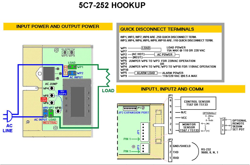
11 SET-UP INSTRUCTIONS FOR MODEL 5C7-252 PC PROGRAMMABLE TEMPERATURE CONTROLLER 1 Connect the appropriate AC power to the controller in accordance with the customer hook-up drawings in the Operating Manual (See the SYSTEM BLOCK DIAGRAM and the MECHANICAL/SYSTEM WIRING DIAGRAM). Select the correct configuration for either 110 VAC (jumper from WP4 to WP6), or 220 VAC (jumper from WP4 to WP3). Connect the AC power between WP2 and WP8. Note: The AC power supply must also match the voltage ratings of the load (heater or cooler). 2. Connect the RS-232 Communications Port from the controller to the RS-232 input on the PC. 3. Turn power on to the PC and temperature controller. 4. Insert the 5C7-252 software disk into the computer A:\ drive. To launch the software from the floppy disk, select START, RUN from your Windows Desktop and then enter A:\MC252.exe and OK. This will load the PC interface into your computer s RAM. 5. The Window s based GUI of the Setup program will appear on your PC monitor. 6. NOTE: If you receive an error message, please refer to Appendix A of the Operating Manual. 7. All selections are made from this menu screen. In the PC COMMUNICATIONS box, select the COMM PORT (1 through 4) which will be your communications link to the controller. Click on the INITIALIZE button and communications should be established with the controller. You should see configuration values displayed in the Set-up window. 8. In the CONFIGURATION box, the various menu selections are used to establish the custom operating criteria for the controller. 9. First, click on the SENSOR TYPE INPUT 1 menu key. Select the sensor type that is appropriate for your application. 10. Click on TIMEBASE: This is the time the controller completes one full cycle, and is expressin seconds. Acceptable values are 0.1 second to 1.0 second. Enter the timebase that is appropriate for your application. DEFAULT: 1.0. This value only really matters when using PID control. The timebase establishes the longest pulse of power that can be used. If the timebase is 1 second, then at full power the AC power is applied for 1 second, and then another second, and so on. Each pulse of power is adjacent to the previous pulse and so this is really like connecting directly to the AC source. However, say that only 50% power is going to be applied. Each pulse of power is only ½ second, ½ second on and ½ second off fills the timebase of 1 second and then this pattern repeats. To supply the equivalent of 25% power using Pulse Width Modulated (PWM), each pulse of power lasts only ¼ second, ¼ second on and ¾ seconds off fills the timebase of 1 second and then this pattern repeats. If the load responds slowly, a 1 second timebase will probably be appropriate. But if the load responds quickly to these pulses then a 1 second timebase may be too slow. For example, consider a very small relay as the load. With a one second timebase you could see the relay opening and closing every half second. With a 0.1 second timebase it may stay open if insufficient power was supplied, and stay closed if sufficient power was supplied. A smaller timebase is more appropriate for loads with a fast reaction time. 11. Next, click on the SET TEMP TYPE INPUT 2 menu key to reveal the options available. DEFAULT: EXT. COMPUTER EXT. COMPUTER (default) allows you to set the desired control temperature using the SET TEMP or VALUE field of the TUNING box. EXT. POTENTIOMETER, EXT. 0 to 5 vdc, and EXT. 0 to 20 ma, are for external set temperature adjustments. The controller s default setting for these three options is the full range of the thermistor input sensor, however you can adjust this range using the step below. 12. Associated with the external set temperature adjustments are the SET TEMP HIGH RANGE and SET TEMP LOW RANGE selections. If you selected the EXT. POTENTIOMETER, EXT. 0 to 5 vdc, and or the EXT. 0 to 20ma option for the SET TEMP TYPE INPUT 2, then these 2 fields permit the selection of limitations on the temperature range of the external adjustments. Enter the desired values for these settings. These set limit values must be within the full range specified for the sensor. DEFAULTS: 100 for HIGH and 0 (zero) for LOW 9
12 13. Now, click on the CONTROL TYPE menu key and select which type is appropriate for your application. DEFAULT: PID CONTROL. DEADBAND CONTROL is an on/off control. PID CONTROL is a proportional/integral/derivative control. COMPUTER CONTROL acts like an electronic variac in that a fixed percentage of power may be applied to the load using the SET TEMP or VALUE field of the TUNING box. (See the step below that describes the SET TEMP or VALUE field for more information.). 14. Clicking on the CONTROL MODE menu key permits the selection of either COOLING MODE or HEATING MODE. In the cooling mode power increases as the temperature rises above the set point temperature. In the heating mode power increases as the temperature falls below the set point temperature. DEFAULT: HEATING MODE. 15. The ALARM TYPE setting permits the selection of available alarm options with this controller. The drop down menu allows for four selections. NO ALARMS indicates that no alarm parameters are desired. SET TRACKING ALARMS allows an alarm to be set with respect to the set temperature and will move, accordingly, with a change of the temperature setting. This option can be used for a high alarm, low alarm, or both settings. FIXED VALUE ALARMS permits the setting of a fixed, absolute temperature either above or below the set point temperature, or both. COMPUTER CONTROLLED is not an actual alarm, but a user activation of the alarm relay via the PC. DEFAULT: NO ALARMS. 16. Associated with the ALARM TYPE configuration are the HIGH ALARM SETTING, LOW ALARM SETTING, and the ALARM DEADBAND selections. These are set in 1 (one) degree increments. If an alarm type has been selected, enter the desired high and/or low alarm temperature values. The ALARM DEADBAND option is for setting the hysteresis of the alarm values. DEFAULTS: 500 for HIGH, 0 (zero) for LOW, and 0 (zero) for DEADBAND. 17. The POWER SHUT DOWN IF ALARM menu key provides two selections. NO OUTPUT SHUT DOWN, which will let the power output stage of the controller to continue to function, or MAIN OUTPUT SHUTDOWN, which disables the power output stage under an alarm condition. DEFAULT: NO OUTPUT SHUTDOWN. 18. The ALARM LATCH option permits the selection of an ALARM LATCH OFF, where the controller will automatically reset if the alarm condition is self-correcting, or ALARM LATCH ON, which will maintain that an alarm condition existed and must be manually cleared. DEFAULT: ALARM LATCH OFF. 19. The ALARM OUTPUT FUNCTION provides a WINDOW ALARM for an on-temperature indication somewhere between the high and low alarm settings, or may be configured to drive an external solid state relay (SSR DRIVE). Refer to the Operating Manual, Appendix D, 5C7-252 Expansion Connector Application, for the external configuration. DEFAULT: WINDOW ALARM. 20. If you choose to use the PLC temperature selection, click the PLC on box. If you select this function then the controllers set temp is disabled: the PID constants will still be functional. By selecting PLC temperatures you are moving the temperature selection from the main controller section to the PLC section. 21. Select the control temperatures desired and enter these set points into the boxes for temperatures 1 through Select the ramp times for temp1 to temp 2: temp 2 to temp 3: and temp 3 to temp 4, and enter into the appropriate boxes. If you do not desire a specific ramp time then enter a 0 into the ramp time box. The time at a selected temperature (soak time) is controlled externally by operation contacts R1 and R The default setting of the four PLC set temperatures is OFF. If you wish to only use one or two of the temperatures then leave the others at OFF. 24. Refer to expansion connector application for additional PLC temperature selection information. 25. Review all of your controller configuration selections. If all the configuration selections are correct for your application, select the Send Box Values button in the CONFIGURATION box to download these settings to the controller. 26. You are now ready to tune the controller. All selections for this portion will occur in the TUNING box displayed on the monitor. The various constants required by the controller to optimize the system performance are entered in this section. 27. The SET TEMP or VALUE is the set temperature value entered in degrees. This temperature is within the range of the input sensor or the limits of low and high set ranges from the controller s configuration setup. (The low and high set ranges are set by you in the SET TEMP LOW RANGE and SET TEMP HIGH RANGE fields of the CONFIGURATION box as described above.) This field can also be used to set the output power manually. That is, instead of setting the desired temperature here, you can set a fixed value for the output power of the controller. If the CONTROL TYPE in the CONFIGURATION box is set to the COMPUTER CONTROL option, you can use the SET TEMP or VALUE field to provide a fixed percentage of power to the +load. This power resolution with an entry of 0 (zero) is equal to 0% power and 24 equals 100%. 10
13 28. Note: You can set the following to their default values and then return to these fields later to tune the controller. 29. When using PID control, PROPORTIONAL BANDWIDTH is the temperature band in which 0% to 100% power will be applied to the load. The acceptable bandwidth values that may be entered are 1.0 to DEFAULT: When using PID control, INTEGRAL GAIN shifts the proportional bandwidth with respect to the set point to compensate for droop. This value is expressed in repeats per minute and the acceptable values that may be entered are.01 to10 repeats per minute.. DEFAULT: When using PID control, DERIVATIVE GAIN senses the rate of rise or fall of the system temperature and adjusts the cycle time of the controller to minimize overshoot or undershoot. This value is expressed in cycle rates per minute and the acceptable values that may be entered are.01 to 10 cycles per minute.. DEFAULT: When using On/Off control, CONTROL DEADBAND is the temperature band where the controller is turned on and off by either rising or falling temperatures where no heating or cooling takes place. This band is expressed in F. and the acceptable values that may be entered are 0.1 F. to F. DEFAULT: Review the tuning parameters for correctness and then select the Send Box Values button in the TUNING box to download these constants to the controller. 34. You are now ready to calibrate your controller. All of these settings are made in the CALIBRATE box. 35. The CALIBRATE box provides additional variables that can be used to fine tune your system s operation. You may want to try controlling with the initial settings prior to entering values in this section. 36. INPUT 1 OFFSET is a manual method of compensating for the sensor 1 temperature and actual control temperature. DEFAULT: If you have entered values in the CONFIGURATON box and they are the desired settings, select the Send Box Values button in the CONFIGURATION box to download these constants to the controller. 38. Initial set-up of your Model 5C7-252 controller is complete. Appendix A Troubleshooting Communications Por Error Cause Solution Comm Port Timeout No power to 5C7-252 Apply power to 5C7-252, review Customer Drawing for proper hookup. Comm Port Timeout Wrong Comm Port selected Check Computer hardware settings and set to the correct Comm Port Comm Port Timeout Incorrect wiring of the Comm Port Check for the correct wiring from to the computer JP3 to the Computer Comm Port Open Error No Comm Port available at this Check computer hardware setting port setting and set to the correct Comm Port 11
14 APPLICATION NOTE Minutes to PID Tuning of the 5C7-252 Controller Tuning the Model 5C7-252 temperature controller involves three variables. (P)ropotional bandwidth, (I)ntegral action, and (D)erivative rate. The control algorithm sums the three values of these terms to determine the output power. P + I + D = % Power Applied Most applications work satisfactorily with only the P and I values used. Start the tuning process by setting the Integral and Derivative functions to zero. Proportional Bandwidth is defined as the temperature range around the setpoint where the controller modulates (proportions) the output power. In a heating application, if the temperature is above the proportional band, the controller output is OFF. If the temperature is below the proportional band, the controller output is ON. Each thermal system has its own time constants determined by the thermal mass of the components and the placement of the sensor relative to the load. To tune the system the bandwidth must be wide enough that the controller can sense a change and react to it before the temperature drifts outside the bandwidth. If the bandwidth is too small the output will oscillate above and below the setpoint, never settling into control. The bandwidth range of the 5C7-252 is 1 to 100. The units are shipped with a default setting of 20. Assuming the controller is configured for your requirements, start the tuning process by applying power with the default settings and observing the system s response. If the system comes into the proportional band and maintains a steady temperature near setpoint, without overshoot, the bandwidth setting is satisfactory or too large. Reduce the bandwidth setting until the system just begins to oscillate. At this point, the bandwidth is too small. Note the bandwidth setting that just caused the system to oscillate, record the period of oscillation for use in determining the Integral Reset setting. To set the proportional bandwidth, multiply the current bandwidth setting by 1.5 and use it as your new bandwidth setting. The system should come into control and maintain a steady temperature near the setpoint. Integral Reset monitors the difference between the set point and the actual temperature. Its function is to slowly change the output power until the difference between actual temperature and set temperature is zero. The function works by integrating the error signal at fixed intervals. These intervals are expressed in repeats/minute. The acceptable range for the 5C7-252 is 0.01 to 10 repeats / minute. Start with a setting determined by the following formula. Integral Reset = 1/ 2(period) Note: Period is expressed in minutes. Example: The system s period of oscillation with narrow bandwidth was 75 seconds. Therefore the suggested Integral Rate is Integral Reset = 1/ 2(1.25 minutes) Integral Reset = repeats/minute For slower response reduce the number of repeats per minute. NOTE: DERIVATIVE RATE IS DIFFICULT TO APPLY. IF YOU ARE NOT EXPERIENCED IN PROCESS CONTROL, ASK FOR HELP NOW! Derivative Rate senses the rate of change of the temperature and allows the controller to anticipate power needed to compensate for rapid changes in system loading. This term is generally used only on very sluggish systems or where very quick response is necessary. The acceptable range for the 5C7-252 is 0.01 to 10 cycles/minute. To determine an appropriate derivative rate, use the following formula. Derivative Rate = Integral Reset / 10 For the example above the Derivative Rate would be.04 cycles per minute. The Derivative function is difficult to use and often causes more trouble than it is worth! 12

15 Oven Industries, Inc. Mechanicsburg PA Phone: Fax: /2004 Rev: A
TETECHNOLOGY, INC Keane Drive Phone: (231) Traverse City, MI Fax: (231)
 Traverse City, MI Fax: (231)") Operation Manual For Model TC-24-25 RS232 Thermoelectric Cooler Temperature Controller May21, 2004 Drawing #3599 Rev. E TETECHNOLOGY, INC. 1590 Keane Drive Phone: (231) 929-3966 Traverse City, MI 49686-8257
Operation Manual For Model TC-24-25 RS232 Thermoelectric Cooler Temperature Controller May21, 2004 Drawing #3599 Rev. E TETECHNOLOGY, INC. 1590 Keane Drive Phone: (231) 929-3966 Traverse City, MI 49686-8257
I/A Series 716C 1/16 DIN Temperature Controller
 Product Specifications I/A Series 716C 1/16 DIN Temperature Controller PSS 2C-1B5 A The Foxboro 716C is a powerful compact, 1/16 DIN, microprocessor-based temperature controller that offers a variety of
TC515 and TC600 Installation Manual. a Winters company
 THERMOLINE TEMPERATURE CONTROLLERS TC515 and TC600 Installation Manual a Winters company Guarantee 12 months Congratulations on the purchase of this new product. Special care with the design, workmanship
Tempco PCT-3000 Series Temperature Control Console with Relay Output for Heating or Cooling Applications
 Instruction Manual Tempco PCT-3000 Series Temperature Control Console with Relay Output for Heating or Cooling Applications Manual PCT-3000 Revision 9/2014 The PCT-3000 series control console incorporates
User Manual. Digi-Sense TC9500 Advanced Multiparameter Temperature Controller with Thermocouple, Thermistor, and RTD Inputs
 User Manual Digi-Sense TC9500 Advanced Multiparameter Temperature Controller with Thermocouple, Thermistor, and RTD Inputs Models 89800-03 and 89800-04 THE STANDARD IN PRECISION MEASUREMENT Table of Contents
User s Manual. TIGER S EYE E-Series Mark V Jockey. TIGERFLOW Systems, Inc Mint Way Dallas, Texas
 User s Manual TIGER S EYE E-Series Mark V Jockey TIGERFLOW Systems, Inc. 4034 Mint Way Dallas, Texas 75237 214-337-8780 www.tigerflow.com TABLE OF CONTENTS Introduction... 4 Sequence of Operation... 5
RC-112 Two Speed Heat Pump 3 Stage Heat / 2 Stage Cool With Energy Efficient Control
 O M N I S T A T ELECTRONIC COMMUNICATING THERMOSTAT Installation Manual RC-112 Two Speed Heat Pump 3 Stage Heat / 2 Stage Cool With Energy Efficient Control Document Number 13I00-5 November, 1997 CONTENTS
Series Digital Controller Instruction Sheet
 216/3/11 Series Digital Controller Instruction Sheet Thank you very much for purchasing DELTA DTC Series Temperature Controller. Please read this instruction sheet before using your DTC series to ensure
DT968C C.T. BATH CONTROLLER
 DT968C C.T. BATH CONTROLLER MANUAL (DT968C, 9-5-01) ICD/HEATEFLEX Page 1 DT968C CONSTANT TEMPERATURE BATH CONTROLLER The Model DT968C is a microprocessor based controller/timer. It monitors temperature
Nov 08 PRODUCT SPECIFICATION SHEET
 Honeywell UDC1200 and UDC1700 MICRO-PRO SERIES UNIVERSAL DIGITAL CONTROLLERS 51-52-03-35 Nov 08 PRODUCT SPECIFICATION SHEET OVERVIEW The UDC1200 & UDC1700 are microprocessor-based 1/16 DIN and 1/8 DIN
VERTEX VT10 SERIES PID OPERATION MANUAL MICROPROCESSOR BASED PID CONTROLLER
 1 VERTEX VT10 SERIES PID OPERATION MANUAL MICROPROCESSOR BASED PID CONTROLLER 1. INTRODUCTION This manual contains information for the installation and operation and tuning of our Vertex VT10 series self-tuning
User Manual. Digi-Sense TC9600 Advanced Multiparameter Temperature Controller with Thermocouple, Thermistor, and RTD Inputs
 User Manual Digi-Sense TC9600 Advanced Multiparameter Temperature Controller with Thermocouple, Thermistor, and RTD Inputs Models 89800-13 and 89800-14 THE STANDARD IN PRECISION MEASUREMENT Table of Contents
Table of Contents SECTION PAGE
 Table of Contents SECTION PAGE SECTION 1 INTRODUCTION................... 1.1 Description.............................. 1.2 Features................................ 1.3 Models.................................
Model 96VTR ¼ DIN Process Controller
 99 Washington Street Melrose, MA 02176 Phone 781-665-1400 Toll Free 1-800-517-8431 Visit us at www.testequipmentdepot.com Back to the Extech 96VTR Product Info Page INSTRUCTION MANUAL Model 96VTR ¼ DIN
Frequently asked questions: Intelligent Transmitter Series
 Frequently asked questions: Intelligent Transmitter Series The Wilcoxon family of Intelligent Transmitters, relay alarms, and communication modules can be used to implement low-cost online vibration monitoring
Tempco Part Number PCT30006 Temperature Control Enclosure with Relay Output for Tote Tank Heating Applications
 Instruction Manual Tempco Part Number PCT30006 Temperature Control Enclosure with Relay Output for Tote Tank Heating Applications Manual PCT30006, Revision 9/20/2016 The PCT30006 control enclosure incorporates
Refrigeration Controller Operator s Manual (HRC) PO Box 6183 Kennewick, WA
 PO Box 6183 Kennewick, WA") Refrigeration Controller Operator s Manual (HRC) PO Box 6183 Kennewick, WA 99336 www.jmcvr.com 1-509-586-9893 Table of Contents TABLE OF FIGURES...1 OVERVIEW OF THE HRC CAPABILITIES...2 INSTALLATION AND
Refrigeration Controller Operator s Manual (HRC) PO Box 6183 Kennewick, WA 99336 www.jmcvr.com 1-509-586-9893 Table of Contents TABLE OF FIGURES...1 OVERVIEW OF THE HRC CAPABILITIES...2 INSTALLATION AND
B-40/B-41 Modulating Temperature Controller
 INSTALLATION & OPERATING INSTRUCTIONS B-40/B-41 Modulating Temperature Controller For Raytherm Boilers & Water Heaters H2 514-4001 WH2 2100-4001 Catalog No. 5000.70 Effective: 12-21-11 Replaces: NEW P/N
TEMPERATURE CONTROL MODULE MODEL R3-TC2
 INSTRUCTION MANUAL R3-TC2 TEMPERATURE CONTROL MODULE MODEL R3-TC2 CONTENTS BEFORE USE... 2 POINTS OF CAUTION... 2 COMPONENT IDENTIFICATION... 2 INSTALLATION... 2 EXTERNAL DIMENSIONS unit: mm (inch)...
UDC1000 and UDC1500 MICRO-PRO SERIES UNIVERSAL DIGITAL CONTROLLERS
 UDC1000 and UDC1500 MICRO-PRO SERIES UNIVERSAL DIGITAL CONTROLLERS EN0I-6041 4/01 PRODUCT SPECIFICATION SHEET OVERVIEW The UDC1000 and UDC1500 are microprocessor-based 1/16 DIN and 1/8 DIN controllers
Temperature Controllers
 Model TEC-4100 1/4 DIN Model TEC-4100 1/4 DIN Temperature Controller Ordering Code: Power Input BOX 1 4 = 90-250 VAC 5 = 11-26 VAC / VDC TEC-4100- Configurable for 4 Programmable Outputs and NEMA 4X/IP65
99 Washington Street Melrose, MA Phone Toll Free Visit us at
 99 Washington Street Melrose, MA 02176 Phone 781-665-1400 Toll Free 1-800-517-8431 Visit us at www.testequipmentdepot.com Back to the Extech 48VTR Product Info Page Instruction Manual English / Español
DSGH. Radiation-Based Detector with GEN2000 Electronics for Density Measurement QUICK REFERENCE GUIDE
 DSGH Radiation-Based Detector with GEN2000 Electronics for Density Measurement QUICK REFERENCE GUIDE Revision History Revision History Version of manual Description Date 1.0 Initial release 051025 1.1
CLEANROOM MONITOR CR3A Network - Installation Instructions
 CLEANROOM MONITOR CR3A Network - Installation Instructions INTRODUCTION The CR3 Series Cleanroom Monitor, was developed specifically to allow for monitoring of confined spaces with accuracy and reliability.
TYPE CM-2201 NELSON SINGLE POINT CIRCUIT MANAGEMENT SYSTEM
 2 Line, 16 Characters/row LCD Display Temperature Input Range -50 C to +500 C -58 F to + 932 F Enclosure NEMA Type 4X Current Rating 30A max (resistive load only) Ambient Temperature -40 C to + 40 C -40
EKC 347 Liquid Level Controller REFRIGERATION AND AIR CONDITIONING. Manual
 EKC 347 Liquid Level Controller REFRIGERATION AND AIR CONDITIONING Manual Contents Introduction...3 Valve compatibility...3 Features...3 Application examples...3 Ordering...3 Operating the EKC 347...4-5
E N G L I S H FIRE ALARM ASPIRATION SENSING TECHNOLOGY QUICK INSTALLATION GUIDE STAND-ALONE FAAST LT MODELS FL0111E FL0112E FL0122E. 367 mm.
 E N G L I S H FIRE ALARM ASPIRATION SENSING TECHNOLOGY QUICK INSTALLATION GUIDE STAND-ALONE FAAST LT MODELS FL0E FL0E FL0E mm mm 0 mm DESCRIPTION The LT FL0 Series is part of the Fire Alarm Aspiration
AutomationDirect. PC35 Configuration Sheet
 Part#: Project: AutomationDirect PC35 Configuration Sheet Name: Date: Main Setpoint (): Cycle 5 INPUT DEFAULT CODE/VALUE Type 1 Dppo OFF Unit [ Offs 0 Spll -150 Spkl 1370 Rsll -150 Rskl 1370 Cycle 6 I/O
I/O ZONE 560/583 USERS GUIDE
 I/O ZONE 560/583 USERS GUIDE 641-224 641-242 641-237 1 Table of Contents Hot Gas Re-Heat Valve On/Off:... 15 THE ZONE CONTROLLER...4 Modulating Re-Heat Valve:... 16 SPECIFICATIONS...5 CONTROLLER COMPONENTS...6
Oakton TEMP 9500 Advanced Multiparameter Controller
 Oakton TEMP 9500 Advanced Multiparameter Controller Models: 89800-03 & 89800-04 Oakton Instruments 625 E Bunker Ct. Vernon Hills, IL 60061, USA 1-888-4OAKTON (1-888-462-5866) info@4oakton.com Contents
RC-90 / RC-90B Single Stage Heat/Cool Thermostat for Zone Control Systems Installation Instructions
 RC-90 / RC-90B Single Stage Heat/Cool Thermostat for Zone Control Systems Installation Instructions DESCRIPTION The RC-90 is a precision digital thermostat designed for 24 VAC single stage heating and
Adaptive CyCLO Technical and HMI User Guide. CyCLO User Guide. Version th December 2017 REV
 CyCLO User Guide Version 2.00 19 th December 2017 REV 2.00 1 Contents 1. Hardware... 3 1.1. Introduction... 3 1.2. Electrical Specification... 3 1.3. Board Overview... 4 1.4. Electrical Installation...
Carbon Monoxide Transmitter
 Introduction The CO Transmitter uses an electrochemical sensor to monitor the carbon monoxide level and outputs a field-selectable 4-20 ma or voltage signal. The voltage signal may also be set to 0-5 or
ENERGY LIGHT USER S GUIDE ENERGY LIGHT USER S GUIDE
 ENERGY LIGHT USER S GUIDE Release January 2001 CONTENTS 1.0 GENERAL CHARACTERISTICS... 4 1.1 MAIN CHARACTERIS TICS... 4 2.0 USER INTERFACE (CODE C5121230)... 5 2.1 DISPLAY... 5 2.2 MEANING OF THE LEDS...
Communications None RS-232C RS-422* RS-485* BCD Transmission output*/** (4 to 20 ma) E5AX- E5AX- L(M)A02 L(M)A03
 E5AX- E5AX- L(M)A02 L(M)A03") Digital Controller A 96 x 96-mm (DIN) Digital Process Controller Optimum PID control with feed-forward control circuitry. High accuracy (+0.3% FS +1 digit max.). Replaceable Output Units. Models with communications
Digital Controller A 96 x 96-mm (DIN) Digital Process Controller Optimum PID control with feed-forward control circuitry. High accuracy (+0.3% FS +1 digit max.). Replaceable Output Units. Models with communications
RC-101 Heat Pump Real Time Pricing System 2 Stage Heat / 1 Stage Cool
 O M N I S T A T ELECTRONIC COMMUNICATING THERMOSTAT Installation Manual RC-101 Heat Pump Real Time Pricing System 2 Stage Heat / 1 Stage Cool Document Number 13I00-4 January, 1997 Copyright 1997 Home Automation,
ELECTRONIC HUMIDISTAT: H270
 ELECTRONIC HUMIDISTAT: H0 ONE OR TWO STAGES HUMIDITY SUPPLY OUTDOOR TEMPERATURE RESET DESCRIPTION The H0 series low voltage, microcomputerbased PI (proportional and integral) humidistats are designed for
F4 Process Controller Installation and Operation Guide
 F4 Process Controller Installation and Operation Guide 1.Introduction 1.1.Highlight Features Space saving, only 55mm panel depth required Higher sampling rate (1mS) results in better control performance
Digi-Sense TC9000 Advanced PID and On/Off Temperature Controller with Thermocouple Input
 User Manual 99 Washington Street Melrose, MA 02176 Phone 781-665-1400 Toll Free 1-800-517-8431 Visit us at www.testequipmentdepot.com Digi-Sense TC9000 Advanced PID and On/Off Temperature Controller with
NELSON CM HEAT TRACE CONTROLLER Installation and Operating Instructions
 NELSON HEAT TRACE CONTROLLER Installation and Operating Instructions Contents 1.0 Introduction 4 1.1 Getting Started 2.0 General Application Information 5 3.0 Installation 6 3.1 Selecting Installation
HAI Omni-Bus Network Installation. 5. Typical Application
 HAI Omni-Bus Network Installation 5. Typical Application HAI Omni-Bus Network Installation Notes 1. Network cable 2. Crimp Connectors 3. Network Termination Plug 4. Jumpers 5. Splitters 6. Power Supply
PF1000 CONTROLLER. for the. Heateflex Corporation 405 E. Santa Clara St. Arcadia, CA TEL: (626) ; FAX: (626)
 ; FAX: (626)") PF1000 CONTROLLER for the AQUARIUS I/II DEIONIZED WATER HEATING SYSTEM Heateflex Corporation 405 E. Santa Clara St. TEL: (626)599-8566; FAX: (626)599-9567 Rev. 07 10/19/10, (PF1000) 1 2 TABLE OF CONTENTS
PF1000 CONTROLLER for the AQUARIUS I/II DEIONIZED WATER HEATING SYSTEM Heateflex Corporation 405 E. Santa Clara St. TEL: (626)599-8566; FAX: (626)599-9567 Rev. 07 10/19/10, (PF1000) 1 2 TABLE OF CONTENTS
Communications* None RS-232C RS-422 RS-485 BCD Transmission output** (4 to 20 ma)
") TEMPERATURE CONTROLLER DIN-sized (96 x 96-mm) Temperature Controller Featuring Advanced PID Control and Heater Burnout Detection Advanced PID control with two degrees of freedom to improve stability and
TEMPERATURE CONTROLLER DIN-sized (96 x 96-mm) Temperature Controller Featuring Advanced PID Control and Heater Burnout Detection Advanced PID control with two degrees of freedom to improve stability and
RCS Residential Control Systems Inc.
 RCS Residential Control Systems Inc. Model TZ16 Z-Wave Communicating Thermostat with Rev P HVAC Control Unit INSTALLATION AND OPERATION MANUAL DCN: 141-00882 Rev 02 5/18/06 This manual applies to the following
INSTRUCTION MANUAL and DETAILED PRODUCT SPECIFICATION TRIPLEX PUMP CONTROL SYSTEM MODEL NUMBER CPC-3. M336 Rev F. November 21, 2000.
 INSTRUCTION MANUAL and DETAILED PRODUCT SPECIFICATION TRIPLEX PUMP CONTROL SYSTEM MODEL NUMBER CPC-3 M336 Rev F November 21, 2000 ÇConsilium Consilium US, Inc. 59 Porter Rd Littleton, MA 01460-1431 USA
Dryer Controller M720
 User Manual Dryer Controller M720 Hardware version 2.00 Software version 2.00 Manual M720 Dryer controller Page 1 of 60 Document history Preliminary version: - Created in April, 2009 Hardware Version 2.00,
ModSync Sequencing System Installation & Operation Manual. For use with Fulton Steam Boilers.
 ModSync Sequencing System Installation & Operation Manual For use with Fulton Steam Boilers. Revision 3.0 8/21/2008 - 2 - Table of Contents Introduction Page 4 Features Page 4 Sequence of Operation Page
Dryer Master DM510 Commissioning Guide
 COMMISSIONING GUIDE Dryer Master DM510 Dryer Moisture Systems Inc. 640 Superior Drive Waterloo, Ontario Phone 519.725.4700 Fax 519.885.4300 USA & Canada Toll Free 1-888-318-0009 E-mail: info@dryermaster.com
ELECTRONIC HUMIDISTAT: H200
 ELECTRONIC HUMIDISTAT: H00 ONE OR TWO STAGES DESCRIPTION The H00 series low voltage, microcomputerbased PI (proportional and integral) humidistats are designed for accurate humidification and/or dehumidification
Software Version 2.01 LEVEL MONITOR MODEL 220
 Software Version 2.01 LEVEL MONITOR MODEL 220 19 April 2000 CONTENTS 1. Introduction 1 1.1 Model Number Designation 2 1.2 Intrinsic Safety Considerations 3 2. Specification 4 3. Operation 6 3.1 Display
Important Supplementary Manual to the main Ezeio manual. 5. Section 2a: Introducing the 2400 input and output expansion field stations.
 1 P age Ezeio v9-120317 Eze Cloud Based Monitoring Systems. Created by Intech Instruments Ltd December 2014 Important Supplementary Manual to the main Ezeio manual. Ezeio Controller and the 2400-A16 input
Table of Contents 1. OVERVIEW SYSTEM LAYOUT SPECIFICATIONS FUNCTION... 11
 Table of Contents 1. OVERVIEW... 3 2. SYSTEM LAYOUT... 4 3. SPECIFICATIONS... 8 3.1 SYSTEM COMPONENTS...9 3.2 PLC INPUTS AND OUTPUTS...9 3.3 FUNCTION KEYS...10 3.4 DEFAULT SET POINTS AND TIMERS...10 4.
ELECTRONIC COMMUNICATING THERMOSTAT
 O M N I S T A T ELECTRONIC COMMUNICATING THERMOSTAT Installation Manual RC-81 Single Stage Heat/Cool Real Time Pricing System Document Number 13I00-2 January, 1997 Copyright 1997 Home Automation, Inc.
CELLTROL II BIOREACTOR CONTROL SYSTEM OPERATIONS MANUAL
 Operation Manual Celltrol II Bioreactor Control System Page 1 of 33 Table of Contents 1) Introduction... 3 1.1) Scope of Document... 3 1.2) Control System Overview... 3 1.3) Introduction to Celltrol II...
Table of Contents SECTION PAGE SECTION 1 INTRODUCTION Description Features Models... SECTION 2 RS-232 COMMUNICATIONS...
 SECTION Table of Contents SECTION 1 INTRODUCTION...................... 1.1 Description............................... 1.2 Features................................. 1.3 Models..................................
Laptop / PC Programming Manual
 Laptop / PC Programming Manual Doc. # Fire PC Program rev B 01.07 This Document is property of Evax Systems, Inc. The Evax Fire Solutions Programmer Components 2 1.0 System Setup 4 1.1 Interface Setup
IntelliPack : 800 Series
 800 Series Models by Function Guide 800T Intelligent Transmitters 800A Intelligent Alarms 890M Math/Computation IntelliPack transmitter units convert sensor inputs to isolated process current or voltage
ESSEX ENGINEERING CORPORATION
 WATER/WASTEWATER TREATMENT CONTROL SYSTEMS AND SUBSYSTEMS 2000 SERIES CONTROL SYSTEMS: 2000 series are for surface mounting inside a control cabinet Model 2024 Electronic Alternator Duplex (two pump) pump
HGM300/RDM800 PREVENTATIVE MAINTENANCE AND TECHNICAL SUPPORT. SECTION 1 HGM300 CPU reset, RDM800 CPU reset, WARM UP notes and HGM300 Self Test
 HGM300/RDM800 PREVENTATIVE MAINTENANCE AND TECHNICAL SUPPORT SECTION 1 HGM300 CPU reset, RDM800 CPU reset, WARM UP notes and HGM300 Self Test SECTION 2 HGM300/RDM800 Mechanical Room layout SECTION 3 HGM300
TC-9102 Applications
 Application Note January 7, 2004 APPLICATION NOTE TC-9102 Applications Configuring TC-9102 Applications...3 Introduction... 3 Key Concepts... 4 TC-9102 Controller... 4 Control Modes...8 Procedure Overview...
IMPORTANT. PLEASE NOTE: The infrared beam path MUST be kept clear of obstructions at all times!
 USER GUIDE English IMPORTANT PLEASE NOTE: The infrared beam path MUST be kept clear of obstructions at all times! Failure to comply may result in the Detector initiating a Fire or Fault signal. Contents
VT4810 SINGLE / DUAL ZONE CONTROLLER INSTALLATION MANUAL
 Thermocouple Type BS4937 (IEC584-3): Outer / + / - BS1843 (Old UK Standard) Outer / + / - US Outer / + / - J : Iron / Copper-Nickel Black / Black / White Black / Yellow / Blue Black / White / Red VT4810
TEMPERATURE CONTROLLER
 TEMPERATURE CONTROLLER E5CX(-H) DIN-sized super-compact (48 x 48-mm) Temperature Controller Featuring Advanced PID Control Advanced PID control with two degrees of freedom improves stability and response
SA100. General Description. Features. Temperature Controller SA100. Corresponding to Various Applications. Simple Mounting on DIN Rail
 Temperature Controller General Description The is a socket mounting type temperature controller and is available for mounting inside the panel or by easily mounting on DI rail. The has features such as
TEMPERATURE CONTROLLER R/S (ADVANCED MODEL)
") OPERATING MANUAL TEMPERATURE CONTROLLER R/S (ADVANCED MODEL) 689-0010 689-0015 Barnant Company 28W092 Commercial Avenue Barrington, Illinois U.S.A. 60010-2392 (847) 381-7050 (847) 381-7053 (Fax) 800-637-3739
OPERATING MANUAL TEMPERATURE CONTROLLER R/S (ADVANCED MODEL) 689-0010 689-0015 Barnant Company 28W092 Commercial Avenue Barrington, Illinois U.S.A. 60010-2392 (847) 381-7050 (847) 381-7053 (Fax) 800-637-3739
Module Features are-configurable, no module jumpers to set
 December 2011 PACSystems* RX3i Isolated Thermocouple Input Module, 6 Channels, IC695ALG306 Isolated Thermocouple Input Module, 12 Channels, IC695ALG312 Isolated Thermocouple Input module IC695ALG306 provides
Rev Pulse Modulating Anti- Sweat Control (PMAC II) Installation and Operation Manual
 Installation and Operation Manual") 026-1501 Rev 5 3-20-03 Pulse Modulating Anti- Sweat Control (PMAC II) Installation and Operation Manual 1640 Airport Road, Suite 104 Kennesaw, GA 31044 Phone: (770) 425-2724 Fax: (770) 425-9319 ALL RIGHTS
026-1501 Rev 5 3-20-03 Pulse Modulating Anti- Sweat Control (PMAC II) Installation and Operation Manual 1640 Airport Road, Suite 104 Kennesaw, GA 31044 Phone: (770) 425-2724 Fax: (770) 425-9319 ALL RIGHTS
Dry Contact Probe DCP (#30008)
") Dry Contact Probe DCP (#30008) The Networked Robotics DCP probe enables network data collection of the state of any normally open or normally closed switch. This product can sense alarm contact outputs
Dry Contact Probe DCP (#30008) The Networked Robotics DCP probe enables network data collection of the state of any normally open or normally closed switch. This product can sense alarm contact outputs
User Manual. Dryer Controller M720
 User Manual Dryer Controller M720 Hardware version 1.00 Software version 1.00 Preliminary version Manual M720 Dryer controller Page 1 of 42 Document history Preliminary version: - Created in April, 2009
RC-2000 Thermostat Installation Instructions
 RC-2000 Thermostat Installation Instructions DESCRIPTION The RC-2000 is a precision digital thermostat designed for 24 VAC heating and cooling systems. The RC-2000 will support the following systems: Single
S304 and S305 Dust Emission Monitors. User Manual. Distributor
 S304 and S305 Dust Emission Monitors User Manual Distributor Version 6.4 30/5/2012 Table of Contents 1. INTRODUCTION... 3 1.1 Safety... 3 1.2 Product overview... 4 1.3 Principle of operation... 4 2. INSTALLATION...
Pioneer-R16 Gas Monitor Operator s Manual
 Pioneer-R16 Gas Monitor Operator s Manual Edition 7/2/97 RKI INSTRUMENTS, INC RKI Instruments, Inc. 33248 Central Ave, Union City, CA 94587 (510) 441-5656 Chapter 1: Description About the Pioneer-R16 Gas
Netbiter Tank Sensor
 For Netbiter Tank Sensor HMS Industrial Networks AB Post address: Box 4126 300 04 Halmstad SWEDEN Visitor s address: Stationsgatan 37 302 45 Halmstad SWEDEN Telephone: + 46 35 17 29 00 Fax: + 46 35 17
Serie Rugghölzli 2 CH Busslingen. Tel. +41 (0) Fax +41 (0)
 Fax +41 (0)") Serie 5000 Tel. +1 (0)5 222 Fax +1 (0)5 222 12 PRODUCT INTRODUCTI PRODUCT INTRODUCTI 5 Series programmable temperature controller is FineTek's mid-range series of controllers. It uses a 12bit analog /
Serie 5000 Tel. +1 (0)5 222 Fax +1 (0)5 222 12 PRODUCT INTRODUCTI PRODUCT INTRODUCTI 5 Series programmable temperature controller is FineTek's mid-range series of controllers. It uses a 12bit analog /
Advanced Autoclave Controller with Recording + 4 Channel Mapping + Pressure Indication with PC Software & Printer Module
 Clavex Plus Advanced Autoclave Controller with Recording + 4 Channel Mapping + Pressure Indication with PC Software & Printer Module PC Software Controller with Graphic Display Printer Module Features
RS485 MODBUS Module 8AI
 Version 1.4 15/04/2013 Manufactured for Thank you for choosing our product. This manual will help you with proper support and proper operation of the device. The information contained in this manual have
R1000 / R1040 / R1080
 R1000 / R1040 / R1080 1 Zone Temperature Controller: Heat-only Heating-off-cooling Three-point stepping DIN-Format: 96mm x 96mm / 48mm x 96mm / 96mm x 48mm Description and operating manual ELOTECH Industrieelektronik
PACSystems* RX3i. Thermocouple Input Module, 12 Channels, IC695ALG412. GFK-2578B October 2011
 October 2011 PACSystems* RX3i Thermocouple Input Module, 12 Channels, IC695ALG412 The PACSystems * Thermocouple Input module IC695ALG412 provides twelve isolated differential thermocouple input channels.
ECO N DATE DESCRIPTION OF CHANGE CHG
 Model Number: M21E-24-DIN Description: The product is a loop powered device which controls an unsupervised dual pole output channel suitable to manage 24VAC loads. The M21E-24-DIN is micro-controller operated,
Mark 25 Ultrapure Water Conductivity Analyzer
 Martek Instruments, Inc. Mark 25 Ultrapure Water Conductivity Analyzer Instruction Manual WARRANTY POLICY Unless otherwise stated, MARTEK INSTRUMENTS, INC. warrants this equipment to be free from defects
Speed and Frequency Seite 1 von 7
 Speed and Frequency Seite 1 von 7 E16 Systems for High Safety Speed ing, all with Triple Modular Redundancy. A choice of versions to meet various demands. Compliant with SIL3 / IEC 61508 and/or API 670.
User s Guide CN616A. Universal 6 Channel ¼ DIN Process Controller. Shop online at omega.com
 TM User s Guide Shop online at omega.com e-mail: info@omega.com For latest product manuals: www.omegamanual.info CN616A Universal 6 Channel ¼ DIN Process Controller omega.com info@omega.com U.S.A. Headquarters:
MODEL SF-10 CONTROL OPERATION AND INSTRUCTION MANUAL
 MODEL SF-10 CONTROL OPERATION AND INSTRUCTION MANUAL The SF-10 Temperature Control () is an efficient boiler operator with a digital LCD display with backlight, a boiler pump output, and an alarm. The
S/601 Controller Installation Manual
 Checked Version Release date QA V4.6.5 PC1 EN 02.07.2012 2011 S/601 Controller Installation Manual FLOW CONTROL PC1 - Pump controller Introduction Thank you for using the S/601 flow, batch and pump control
TEC Controller Terminal Box Controller (VAV) - with Hot Water Reheat, Application Application Note Building Technologies
 - with Hot Water Reheat, Application Application Note Building Technologies") TEC Controller Terminal Box Controller (VAV) - with Hot Water Reheat, Application 2023 Application Note 140-1052 Building Technologies Table of Contents Overview... 4 Hardware Inputs... 6 Hardware Outputs...
TEC Controller Terminal Box Controller (VAV) - with Hot Water Reheat, Application 2023 Application Note 140-1052 Building Technologies Table of Contents Overview... 4 Hardware Inputs... 6 Hardware Outputs...
21-light Remote Annunciator. Owner s Manual
 21-light Remote Annunciator Owner s Manual Annunciator Description... Inside Font Cover Detailed Specifications... 1 Environmental Specifications... 1 Power Supply Requirements... 1 Communication With
PROCON MODEL 7200 ENVIRONMENTAL CHAMBER CONTROL MODULE. 12/12/01 Rev 01
 PROCON MODEL 7200 ENVIRONMENTAL CHAMBER CONTROL MODULE 12/12/01 Rev 01 PROCON MODEL 7200 ENVIRONMENTAL CHAMBER CONTROL MODULE The Model 7200 Environmental Chamber Control Module is a microprocessor based
VAV Thermostat Controller Specification and Installation Instructions. Model TRO24T4XYZ1
 Model TRO24T4XYZ1 Description The TRO24T4XYZ1 is a combination controller and thermostat. The VAV Thermostat Controller is designed for simple and accurate control of any variable air volume box in a number
Micro-controller X C C1 C2 AL1 AL2 AL3. Model: PXR4/5/9. Operation Manual SEL PXR. ECNO:406e
 C C1 C2 AL1 AL2 AL3 Micro-controller X Model: PXR4/5/9 PXR SEL Operation Manual ECNO:46e Table of Contents Part Names and Functions... 6 Operations... 7 2-1 Parameter list... 7 2-2 Basic operations...
ORP (mv) Controller Model: ORP-XP2. UP DOWN ENTER Time & Date Main Menu Alarm Reset
 Controller Model: ORP-XP2. UP DOWN ENTER Time & Date Main Menu Alarm Reset") Instruction Manual ORP (mv) Controller Model: ORP-XP2 Power Control Alarm Comms UP DOWN ENTER Time & Date Main Menu Alarm Reset Supplied by: Convergent Water Controls Pty Ltd 2/4 Huntley Street, PO Box
Instruction Manual ORP (mv) Controller Model: ORP-XP2 Power Control Alarm Comms UP DOWN ENTER Time & Date Main Menu Alarm Reset Supplied by: Convergent Water Controls Pty Ltd 2/4 Huntley Street, PO Box
Temperature + Humidity (%RH) Control & Recording System with 8 / 16 Channel Mapping. Touch Panel PPI
 Control & Recording System with 8 / 16 Channel Mapping. Touch Panel PPI") HumiTherm Ultra Temperature + Humidity (%RH) Control & Recording System with 8 / 16 Channel Mapping Mapping Unit Micro PLC Control Unit Touch Panel Touch Operation Panel PPI HumiTherm Ultra GSM Module
HumiTherm Ultra Temperature + Humidity (%RH) Control & Recording System with 8 / 16 Channel Mapping Mapping Unit Micro PLC Control Unit Touch Panel Touch Operation Panel PPI HumiTherm Ultra GSM Module
ProTalk. Expander. Operating Manual Model B1292. July 28, 2009 Rev. 1.01
 ProTalk Expander Operating Manual Model B1292 July 28, 2009 Rev. 1.01 TABLE OF CONTENTS 1. Introduction... 1 2. Installation... 2 2.1 Wiring Diagram... 3 3. Operations... 4 4. Programming (B1225 Mode)...
MYRIAD TRIPLEX PUMP CONTROLLER INSTRUCTION MANUAL
 MYRIAD TRIPLEX PUMP CONTROLLER INSTRUCTION MANUAL MYRIAD TPC VISIT OUR WEBSITE SIGMACONTROLS.COM MYRIADI&O062705 2 TABLE OF CONTENTS INTRODUCTION 3 Ordering Information Specifications Features WIRING 7,8
C-Bus Four Channel General Input Unit Installation Instructions
 C-Bus Four Channel General Input Unit Installation Instructions 5504GI Series REGISTERED DESIGN REGISTERED PATENT Table of Contents Section...Page 1.0 Product Range... 3 2.0 Description... 3 3.0 Capabilities...
PERMACONN PM1030 Includes DI300. Installation Manual
 PERMACONN PM1030 Includes DI300 Installation Manual Radio Data Comms Unit 5/20-30 Stubbs Street Silverwater NSW 2128 Telephone: 02 9352 1777 Facsimile: 02 9352 1700 Introduction The PERMACONN system provides
RANGER 8600 DOWNLOADABLE CONTROL COMMUNICATOR INSTALLATION MANUAL
 RANGER 8600 DOWNLOADABLE CONTROL COMMUNICATOR INSTALLATION MANUAL TABLE OF CONTENTS GENERAL DESCRIPTION... 2 STANDARD AND OPTIONAL PARTS LIST... 2 PARTS DIAGRAM... 3 TERMINAL DRAWING AND SPECIAL NOTES...
Operational Overview and Controls Guide
 DOCUMENT: ECSEQ2-2 EFFECTIVE: 02/26/10 SUPERSEDES: 02/14/07 Operational Overview and Controls Guide Standard Two or Three Pump Type VFD Booster Controls 6700 Best Friend Road. Norcross, GA 30071. (770)
TEC Controller Terminal Box Controller (VAV) - Series Fan Powered with Hot Water Reheat, Application Application Note
 - Series Fan Powered with Hot Water Reheat, Application Application Note") TEC Controller Terminal Box Controller (VAV) - Series Fan Powered with Hot Water Reheat, Application 2025 Application Note 140-1054 Building Technologies Table of Contents Overview... 4 Hardware Inputs...
TEC Controller Terminal Box Controller (VAV) - Series Fan Powered with Hot Water Reheat, Application 2025 Application Note 140-1054 Building Technologies Table of Contents Overview... 4 Hardware Inputs...
E N G L I S H FIRE ALARM ASPIRATION SENSING TECHNOLOGY QUICK INSTALLATION GUIDE ADDRESSABLE FAAST LT MODELS MI-FL2011EI, MI-FL2012EI AND MI-FL2022EI
 E N G L I S H FIRE ASPIRATION SENSING TECHNOLOGY QUICK INSTALLATION GUIDE ADDRESSABLE FAAST LT MODELS MI-FL0EI, MI-FL0EI AND MI-FL0EI mm mm 0 mm DESCRIPTION The LT MI-FL0 Series is part of the Fire Alarm
MT-374B/364B Operation User s Guide. The Anti-Sweat Energy Saving Controller user s manual
 MT-374B/364B Operation User s Guide Parker Hannifin Canada Micro Thermo Technologies TM 12855 Brault Street Mirabel, QC J7J 0C4 Office phone 450-668-3033 Introduction The Anti-Sweat Energy Saving Controller