System description LG 66E-TL11 with time lock function
|
|
|
- MargaretMargaret Parsons
- 5 years ago
- Views:
Transcription
1 System description LG 66E-TL11 with time lock function Keypad 3125 This TL11-Software is available for the locks: COMBOGARD TL11 SAFEGARD SWINGBOLT TL11 V1.20 SAFEGARD OVERRIDE 6441M-TL11 With entry path 3125 or T8030 with time delay display. Keypad T8030 Protocol reader Multicode 1 Control code ( ID # 0 ) 1 Manager ( ID # 1 ) 8 Users ( ID # 2-9 ) Programms (per PC programmable) Manager mode = controls 9 opening codes, each code can open individually Dual mode = two valid codes must be entered, in order to open Time Delay = delay time from 1-99 min. Opening window 1-19 min. Override mode = user ID # 9 can open immediately (cash-carrier code) Time lock functions (per PC programmable): Weekly program with eligible time windows. Holiday program and programmable open on normally closed days (f.i. open Sundays). Immediate locking: unique time blocking adjustable by the manager (1-99 hrs.) or open extension. Or opening delay. Protocol-record: In the lock, the last 479 events with time, date, user# and action are stored and selected or printed by the PC. Hold-up alarm: In all programs a hold-up alarm can be programmed. Remote blocking or -releases: Switchable over the alarm box or locking device "SP" Box 334. Connection at alarm facilities: Possible over locking device "SP", inclusive 12V power supply out of the alarm system or Alarmbox PN Power supply: 9V alkaline batteries or with SP box12v from the alarm system. Assembly: The locks have standard mounting dimensions and are applicable in all positions and ready to be plugged in. 1
2 OPERATING INSTRUCTIONS LG 66E-TL11 MULTICODE-TIME LOCK Keypad 3125 Locks: 6040-TL11, 6260-TL11, 6441M-TL11 General Each key push will be confirmed with a signal (tone and LEDflash) a correct code input results in a double signal, a false code results in a triple signal. A pause longer than 10 seconds deletes all past inputs and a restart must be made. Factory code/manager Opening is not possible with activated time lock. The time lock with a 2 second-long tone will be indicated to the user. Code input: Opening: Dual mode-operation: (must be programmed) Locking: Manipulation locking: Changing code: Always with door opened Type a numeric code with 7 digits or a word with 7 letters. (f.i. 1LA GARD = ). User number + 6 letter word or 6 digit code. After the correct code input (double signal) the lock stays open for 3 seconds. Opening takes place depending upon the used lock: a) COMBOGARD 6040 = turn keyboard 90 to the RIGHT (clockwise direction) up to stop. b) SWINGBOLT 6260 = turn door handle in open position. c) OVERRIDE 6441M = turn dial to the RIGHT up to stop. If the door is not opened during opening procedure (3 seconds), lock blocks automatically. Two valid codes must be entered, in order to open. The sequence is at choice; two of all valid codes will open. According to the used lock: a) COMBOGARD 6040 = turn the keyboard back to stop (left) b) SWINGBOLT 6260 = turn bolt work handle in CLOSE position c) OVERRIDE 6441M = turn dial at least 1 turn to the left (no stop!) IMPORTANT Always check if it is locked. After 4 incorrect attempts after one another the lock is blocked for 5 min., after that it blocks already after 2 incorrect attempts. During this locking time, the LED blinks every 10 seconds. A keystroke is rejected with a 3-time-signal. 7 times 0, old code, 2 x new code user can always or readjust its code. Enter old code and hold last number until LED is on. Press 0 and Enter new code (double tone) and enter your new code again. (double tone). In case of an incorrect code (3-time-signal) or an interval longer than 10 seconds during readjusting the old code remains. In case a new code is not accepted (3-time-signal), this code is too similar to an already existing code. Select new code. Try new code several times! 2
3 Hold-up alarm: (must be programmed) Time delay: (must be programmed) Power supply: In case of extortion the (silent) alarm can be set off by entering last digit of combination(s) one number higher or one number lower. (f.i. your last digit is 9 the alarm will be set off if you enter 8 or 0). Lock functions don t change and are similar to your opening code. After entering a correct code the time delay begins, recognizable by a LED-signal per second. At the end of the delay, the opening window begins, recognizable by a double signal and 2 LED-signals per second. As well as a soundsignal every 10 seconds. During the opening window, a valid code must be entered in order to open. In dual mode, two valid codes must be entered in the opening window in order to open. If no valid code is entered during the opening window. Time Delay has to be activated again. 1. The battery box is located at the inside of the door for entry 3125 or for the entry 3750 the compartment is in the bottom. If the batteries run out, a series of sounds will be heard when opening. Use ALKALINE-batteries only! In order secure the time accuracy of the records, the battery change has to be carried out within 1 minute. In case battery change is forgotten, a 9V-ALKALINE-battery has to be held on the emergency power supply breaker points as long as code entry and opening took place. The codes remain stored without power supply. 2. In case there is a connection with an alarm system, the power supply may be used from there. Security advice Store code carefully. Don t use personal data (Telephone nr. Date of birth etc.) as your code. LED+Sound signals: 1 x short Input confirmation 2 x short Correct code 3 x short Wrong Code, no acceptance 6 x short Remote locking, Control system disabled 2 x short, long tone (2 sec.) Time lock active 2 x short, long tone (6 sec.) Power cut, synchronise lock LED every 10 sec. 1 flash Penalty time after wrong code LED 1 x per sec Time delay active LED 2 x per sec. opening window and tone every 10 sec. Opening window - time activated Series of tones, ca. 3 sec. Battery low 3
4 PROGRAMMING-MANAGER LG 66E -TL11 MULTICODE TIME-LOCK Manager-functions a) Changing manager-code (ID-Nr 1) Function 0 b) Install users (ID-Nr. 2-9) Function 1 c) Block users Function 2 d) Remove users Function 3 e) Immediate locking Function "4" f) Switching summer-/wintertime Function "5" g) Time synchronisation, time lock program Function "6" h) Data reading Function 7 i) Install delay time Function 9 Activate manager code Lock can be opened with factory code To activate manager function, manager code or control code has to be enrolled. a) Changing manager-code Enter factory code (f.i. previous code) and keep last digit pushed in until LED stays on, press 0 and enter new code (double signal), to confirm the code enter the code again (double signal) LED extinguished. New code is active. When entering a wrong code or taking a pause longer then 10 seconds your previous code stays active. b) Install users Dual code see (*) c) Block users Dual code see (*) d) Remove users Dual code see (*) e) Immediate locking (***) Dual code see (*) Or opening delay (**) f) Summer-/wintertime switch (***) Dual code see (*) Enter manager-code and keep last digit pushed in until LED stays on, press 1 (double signal), enter user-id Nr. f.i. 2 (double signal), enter user code (double signal) to confirm, enter the code again. (double signal) LED extinguished. In case a new code is not accepted (3-time-signal), this code is too similar to an already existing code. Select new code. Enter manager-code and keep last digit pushed in until LED stays on, press 2 (double signal), enter user-id-nr. f.i. 2 (single signal), LED extinguished. User (nr. 2) is blocked until he is admitted with function 1 and ID Nr. 2. Enter manager-code and keep last digit pushed in (double signal) until LED stays on, press 3, (double signal) and enter id-nr. f.i. 2 (single signal) LED extinguished. User (nr.2 ) is removed. (Has to be programmed in time lock program). Immediate locking enables manager to enter a single time lock from 1-99 hrs. Enter manager-code and keep last digit pushed in till repeated double signal (LED on), press 4 (function 4), (double signal) and enter 2 digits closing times (f.i.. "02" for 2 hours), (double signal) and confirm closing hours (enter "02" again). Thereupon the lock will be closed once for 2 hours. Switch has to carried out before the switch days (last Sunday March/October), otherwise there will be a time difference of 1 hour. Enter manager-code and keep the last digit pushed until LED is on, press "5" (function 5) and for wintertime "0" or summertime "1" (-/+ 1 hour). g) Time synchronisation (***) Time differences between the time lock program and PC-time (real time) will be synchronised according to PC-program TL11-TIMELOCK / Sync only and through manager code function 6. Recommended every 6 months, at latest after 4 years. (*) Dual code (4 eyes-principle) to program enter a valid user code before control code. (**) Is an onetime only immediate extension from the opening time and will be displayed as an immediate locking. (***) Does not work when time lock active. 4
5 h) Data reading/protocol Preparation on PC For windows operating systems 95/98 or later. Program LG-View v3.30 is loaded and a Port COM with 1200 bauts, non parity, 8 databits, 1 stopbit is set. Activate LG VIEW v3.30 program and store corresponding port in CONFIGURATION. Activate summer-/wintertime =DST= Daylightsavingtime and set switch dates (last Sunday in March and October) Differences in time on the PC-clock result in time differences in the registered events! The last 479 events are listed in the lock with date, time. and user nr. and can be read outside by the manager through an interface cable. Activate program LG View v3.30 and click on the safe symbol start acquisition. Put Interface (PN 42160) in PC-Port-Com and put connector in the key reader. Read data/protocol Enter manager code and keep last digit pushed in (LED on) press key 7 (function 7). Data is transferred from the lock into the PC and visible as list. The list starts with AUDIT send and PC time. When a? becomes visible behind the sentence instead of OK the battery change took longer than 5 minutes. The times listed have to be adjusted with the currentless period or will be set at a time with corresponding date. The sequence of the events is unchanged. Select filter-functions (user nr., events or time) in search -field and activate filter with a right mouse-click. The filtered data are listed in red. With SAFE the data will be saved in the PC with a file-name ending on LOG. Open this file with Load. With print the list will be printed. With Infos you ll find the lock- and user-status Enrolled = active Installed = active and not changed Disabled = disabled Deleted = deleted Blocked = blocked, not allowed in setup With "TIMELOCK" you ll find the time lock values. i) Opening delay Time delay-override Manager can program an opening delay with function 9. Delay Time from 1-99 minutes and the opening window from 1-19 minutes can be established in a 4-digits block, at which the first 2 digits are the Time Delay minutes and the other two digits are the opening window minutes. Example: 10 minutes delay time and 5 minutes opening window the 4- digits block is Enter manager code and keep last digit pushed in (LED on). Press 9 and time block 1005 (double tone), confirm 1005 (LED off) Changes in time value can only be made in opening window. If Time Delay (TD-Override) is set, user with id-no. 9 can open immediately. In case of dual code, code if ID-NO. 9 has to be entered as a second code. This "override"-code id-nr. 9 can only be installed in opening window. 5
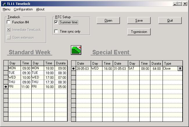
6 Activating the time lock: Week program: Holiday program: (Special events) After programming the lock, time lock functions can be activated by the PC. The TL11 TIMELOCK program will be loaded and activated on your PC. SYNC Only (time synchronising) has been pre programmed and is deactivated by clicking. Click time lock Activ and if desired- immediate Lock as well as Summer Time if programming takes place in summer time. There are 31 time windows available for both week programs and holiday programs. Choose Weekday and put in hours of opening (from-until). Enter date and closing time (from-until). Closing time of holidays can be one week at most. It is possible to program a holiday following the other immediately. Transferring time lock data to the lock: Modifying the time lock: Time synchronising: Click the safe icon on the PC, Interface in the PC-Com-Port and insert the connector in the key reader. Enter control code 8 and manager code 6. Control code: 0 (keep pushed), keep pushed (LED on). Keep manager code pushed until double signal 7 shows (manager function 6). Data transfer starts and ends when END appears on the last line of the left data window. Enter times in TL11 TIMELOCK program again, and transfer data to the lock. Time lock values will be overwritten by the new ones. Resetting is not necessary. Time difference between the time lock program and the PC time (real time) can be synchronised by means of the PC program TL11 TIMELOCK. Activate summer and click when programming takes place in summertime. SYNC Only already has been activated. Enter manager code and a 6 (manager function 6 ). It is recommendable to repeat this every 6 months, and after 4 years at the latest. 6
7 7
8 CONTROL CODE LG 66E-TL11 MULTICODE-TIME LOCK Control code-function: Change code = control function "0" Read data/protocol = control function "7" Cancel immediate locking = control function "8" with manager function 4 (in locked condition) Change summer/wintertime = control function "8" with manager function 5 Time synchronisation = control function "8" with manager function 6 Manager reset (set-up) = control function "8" with manager function 8 Control code is 8-digits and can t open. When programmed, control code is set to factory code ( ) and has to be changed before functions are active. Access to control code functions: Keep "0" pushed in until double signal sounds again and enter control code and keep last digit pushed in until (LED on). Enter function number Change control code: (Function 0) Keep "0" pushed in until double signal sounds again, enter old control code and keep last digit pushed in (LED on). Enter"0" (function "0" = change code) and enter new 8-digits code and confirm the new code (LED off). Control- and manager code are programmable after first code change. (enrolled) Example: (PC-code); "0" (function 0); (f.i.); Read data/protocol: (Function 7) In PC (Windows 95/98 or later) program LG VIEW TL11 has to be loaded. A COM-Port (1200 bauts, non parity, 8 databits, 1 stopbit) has to be set. Put interface (PN42160) in PC-Port and plug in the connector in the opening of the key reader of the input pad. Open LG VIEW TL11 program on your PC and store port under "Configuration". Set summer-/winter time data (last Sunday march/october). Click on safe symbol (next option is STOP for data interruption). Enter control code on keyboard of the lock and 7 (Function 7): Example: 0, , 7. File transfer begins - see counting left under - on PC display. After file transfer the display has to start with AUDIT SEND and actual time (PC-time). 8
9 Filter functions: By clicking on the file you can choose date-search, search events or search user. Click "Reset Filter" and the complete file appears sorted on time. The file can be saved with "SAVE" and be opened with "LOAD". Printing can be done with "Print". With "Infos" you ll find the accurate lock and user status: Enrolled = active Installed = active and not changed Disabled = disabled Deleted = deleted Blocked = blocked, not allowed in setup With TIMELOCK the time lock-values can be retrieved. In the lock 479 actions are stored and are not erasable. Control code-multifunction 8: Cancel immediate locking: Change summer-/wintertime at time lock : Load or overwrite time lock program: Manager reset: Long current interruption (longer than 3 min.) These functions can only be carried out together with the manager code and the manager-functions (4 eyes-principles). Enter control code and function no. 8 enter manager code and function 4 and enter "00" (blocking hours) and confirm. Enter control code and function no. 8 enter manager code and function no. 5 press "0" for wintertime or "1" for summertime. (+ 1 hour) See operating instructions "PC-Programming-time lock. Lock has to be connected with PC. Enter control code und function no 8, enter manager code and function no. 6. Transfer of the time lock program into the lock starts when 0 is pressed on the keypad. Enter control code and function no. 8, enter manager code and function Nr. 8. Lock sends a long tone (0,5 sec) and is in SET- UP-mode (opens with "1") and has to be programmed again (see instructions PC-set-up TL11). If after entering opening code a 6 sec. long signal sounds the clock of the lock stands still due to a long current interruption. Lock is blocked. Synchronise lock time with control code 8 and manager code 6 with PC. 9
10 PC-PROGRAMMING LG 66E-TL11 SET-UP Factory mode: (Set-Up-Mode) Lock programming: In factory mode lock opens with "1" und activates the alarm output. Lock can be mounted and be programmed later. On the PC (laptop) operating systems Windows 95/98 or later has to be installed. A COM-port (1200 bauts, non parity, 8 databits, 1 stopbit) has to be established. Load and call program "TL11 setup" Click "Configuration" and select PC COM-port. Click on desired lock programs in the respective boxes and activate users. Activated (installed) users have a code that can be changed or deleted after programming. Removed (deleted) users can be installed by the manager Non activated (blocked) users can not be installed by the manager afterwards In case of TD-Override User ID#9 ID has to be active. In dual-mode operation next to the manager at least one user has to be active. "Disable opening" click (remote control) SN click "Activ", so the original serial number will be registered. Send PC-set-up to the lock: Change from factory mode: Program change: Put interface cable (PN42160) in PC and insert the connector in the key reader (Software TL11, V1.01) click "Transmit" on the PC-display. Push "0" on the locks keyboard. Data that is transmitted into the lock appear at the display The transfer is complete, if END appears in the lowest line. Enter control code (PC-program 8x"5"). To carry out functions, control code has to be changed., ( ) (LED on) "0" (f.i.), (LED out). New control code is Reset before changing the lock program, than new set-up. Manager-Reset: Enter control code function 8. Enter manager code, function "8", which will be followed by a long signal (0,5 sec.). The lock is in factory mode. Hardware-Reset: Lock status: In case the control code is unknown, a reset can be executed by means of the RESET-BOX (PN6066). Unplug battery from the lock. Push the "0" button for ca. 5 min. and plug the RESET-BOX in the BAT-connection, which is followed by a longer signal (0,5 sec). The Reset-Box requires a connected 9V-ALKALINEbattery. The lock is in FACTORY MODE. Disconnect Reset-Box and plug battery in the lock again. Lock opens with 1. The lock indicates its status connecting the battery: Long signal (0,5 sec.): Lock in set up mode double signal: Lock has been programmed 10
Facts about EM2050. MLS Software. EM2050 RotoBolt Electronic SwingBolt Lock USER INSTRUCTIONS To open (dual combo): AND
: AND") MLS Software EM2050 RotoBolt Electronic SwingBolt Lock USER INSTRUCTIONS VdS Class 2, EN1300 Class B, UL Listed, DNV Listed, IMP Class 2 The lock operates with a numeric 6-digit or 7-digit code. Each key
MLS Software EM2050 RotoBolt Electronic SwingBolt Lock USER INSTRUCTIONS VdS Class 2, EN1300 Class B, UL Listed, DNV Listed, IMP Class 2 The lock operates with a numeric 6-digit or 7-digit code. Each key
Auditcon 2 Series Commercial Safe Locks Models 52 / T52 / 252/ 552
 x Auditcon 2 Series Commercial Safe Locks Models 52 / T52 / 252/ 552 The Auditcon Legacy The Auditcon family of electronic locks was developed to address the security requirements of a broad range of retail,
Operation Manual Fighter ProVision Software. Version: 0.0 Revision: 1
 Operation Manual Fighter ProVision Software Version: 0.0 Revision: 1 TABLE OF CONTENTS 1. Introduction 5 2. Software Installation 5 3. PC Users 6 3.1 Introduction 6 3.2 Default Code 6 3.3 Edit PC User
Version 1.03 January-2002 USER S MANUAL
 Version 1.03 January-2002 1 USER S MANUAL 2 Version 1.03 January-2002 System Details CUSTOMER:...... PHONE:... FAX:... INSTALLED BY:...... PHONE:... FAX:... MAINTENANCE & SERVICE:...... PHONE:... FAX:...
Maximum reliability. Safe Locks
 Maximum reliability Safe Locks LA GARD asic Series at a Glance The LA GARD asic Series electronic combination locks are the industry standard for security and reliability, at an economical price. The asic
Added password for IP setup page : Password must be in IP format!
 NETWORK POWER MONITOR Release : 21 August 2014 Hardware Version : Version 7 Firmware version 1.00 PC Application Software : Version (latest)...2 Added password for IP setup page : Password must be in IP
Auditcon 2 Series Commercial Safe Locks. Models 52/T52/252/552
 Auditcon 2 Series Commercial Safe Locks Models 52/T52/252/552 The Auditcon Legacy The Auditcon family of electronic locks was developed to address the security requirements of a broad range of financial,
SK642 THE TELEPHONE DIALER REQUIRES A LAND TELEPHONE LINE TO MAKE OUTGOING CALLS AND ELECTRICITY.
 SK642 WIRELESS WATER ALARM SYSTEM WITH AUTO DIALER OWNER'S MANUAL AND SET UP INSTRUCTIONS. Thank you for choosing Ideal Security s Wireless Water Alarm with Telephone Dialer. Please read through complete
Ref.1067/032 Ref.1067/042
 DS1067-033A Mod. 1067 LBT8631 BUS CONTROL PANEL 8/32 INPUTS Ref.1067/032 Ref.1067/042 USER MANUAL TABLE OF CONTENTS 1 PREFACE... 5 2 COMMAND DEVICES... 6 2.1 1067/021 DISPLAY KEYPAD... 6 2.2 ELECTRONIC
FCD-wire Contents. List of Figures
 FCD-wire Contents FCD-X21 Configuration 1 Introduction... 1 2 Opening the FCD Application... 1 3 FCD Window... 2 4 FCD LEDs... 3 5 Configuration Operations... 4 FCD Info...4 FCD System Info...5 FCD Interface
Model: Touch-RF. 1 Wireless Series
 Model: Touch-RF Model: Touch-RF 1 Wireless Series Table Of Contents Product Image 1 Locking the Keypad 18 Table of Contents 2 Temperature Control 19 What is a Programmable Room Thermostat? 3-4 Hot Water
Thank you for choosing Ideal Security s Home Security System with Telephone Dialer.
 SK618 WIRELESS ALARM SYSTEM WITH AUTO DIALER OWNER'S MANUAL Thank you for choosing Ideal Security s Home Security System with Telephone Dialer. If at any time during your installation you have any questions
Thank you for choosing Ideal Security s Home Security System with Telephone Dialer.
 SK618 WIRELESS ALARM SYSTEM WITH AUTO DIALER OWNER'S MANUAL Thank you for choosing Ideal Security s Home Security System with Telephone Dialer. If at any time during your installation you have any questions
Laptop / PC Programming Manual
 Laptop / PC Programming Manual Doc. # Fire PC Program rev B 01.07 This Document is property of Evax Systems, Inc. The Evax Fire Solutions Programmer Components 2 1.0 System Setup 4 1.1 Interface Setup
DI220 Using the Optional Docking Station The maintenance and operating functions of the Micro IV can be automated with the Micro IV Docking Station.
 DI220 Using the Optional Docking Station The maintenance and operating functions of the Micro IV can be automated with the Micro IV Docking Station. The following steps outline the correct sequence to
AGRI-ALERT 9600 ALARM SYSTEM USER MANUAL
 AGRI-ALERT 9600 ALARM SYSTEM USER MANUAL M 890-00279 rev. 14 K 895-00004 rev. 00 Manufacturer: Viatron Electronics 5200, Armand-Frappier St-Hubert (Quebec) Canada J3Z 1G5 WARNINGS The warranty can be void
ALARM SYSTEM USER S MANUAL Rev
 ALARM SYSTEM USER S MANUAL Rev.06 890-00011 Manufacturer: Viatron Electronics 3514 1st Street, St-Hubert (Quebec) Canada J3Y 8Y5 WARNINGS the warranty can be void if the Agri-Alert 2400 is used in a manner
Alarm Control Panel WIC-16Z4P WIC-5Z2P. User Instructions
 WIC-16Z4P WIC-5Z2P User Instructions Page : 2/14 INDEX # Function Page 1 Add a New User Code 11 2 Arm or Disarm All Areas or Disarm Selected Areas (Partitioned System) 8 3 Arming the System (Away Mode)
Security System. User s Guide for the Text Command Center
 User s Guide for the Text Command Center MY ALARM COMPANY IS: CALL BEFORE TEST: THIS SECURITY SYSTEM IS CONNECTED TO TELEPHONE NUMBER: THE SECURITY CONTROL PANEL IS CONNECTED TO THE PHONE JACK LOCATED:
SOFTWARE VERSION 2.20 CONTROL PANEL RESET:
 -961112-0002 SOFTWARE VERSI 2.20 CTROL PANEL RESET: Installer lock must be unlocked. ( 255: enter any value other than 147) Power down reset (1) Remove battery and AC to power down the unit. (4) Wait 3
DS7446KP. User Guide. Keypad
 DS7446KP EN User Guide Keypad DS7446KP User Guide Command Quick Reference Command Quick Reference Command Type Basic Arming Commands Advanced Arming Commands System Disarming Commands Command Turn the
SOFTWARE VERSION 2.20 CONTROL PANEL RESET: Installer lock must be unlocked. (Address 255: enter any value other than 147)
") -961112-0003 SOFTWARE VERSI 2.20 CTROL PANEL RESET: Installer lock must be unlocked. ( 255: enter any value other than 147) Power down reset (1) Remove battery and AC to power down the unit. (4) Wait 3
-961112-0003 SOFTWARE VERSI 2.20 CTROL PANEL RESET: Installer lock must be unlocked. ( 255: enter any value other than 147) Power down reset (1) Remove battery and AC to power down the unit. (4) Wait 3
HEXA PROGRAMMING: STREAMLINED SECTION PROGRAMMING
 -961212-0004 SOFTWARE VERSION 3.10 CONTROL PANEL RESET: Installer lock must be unlocked. ( 058: enter any value other than 147) Power down reset (1) Remove battery and AC to power down the unit. (2) Connect
CA60Plus. Installation manual
 CA60Plus Installation manual WARNING This manual contains information on limitations regarding product use and function and information on the limitations as to liability of the manufacturer. The entire
User s Guide. SUB-MA7240O-0001.OG.Solution doc. Created: 6/05/03. Last Updated: 23/09/03. MA7240AO-0001 Version 1.0
 User s Guide SUB-MA7240O-0001.OG.Solution40-111.doc Created: 6/05/03 Last Updated: 23/09/03 MA7240AO-0001 Version 1.0 2 Table Of Contents User List...6 Quick Reference..7 Features...7 Keypad User's Guide...8
BURGLAR ALARM PANEL BS-468
 BURGLAR ALARM PANEL BS-468 Contents 1. Description... 3 2. Instructions for the user... 4 2.1Basic operations... 4 Complete system.... 4 Split system.... 4 2.2 Armed system indication... 5 2.3 Advanced
PWM. Solar Charge controller with Ethernet. Solar Smart PWM 20Amp. Hardware Description : Release : 19 June 2014
 Solar Charge controller with Ethernet Release : 19 June 2014 Hardware Version : Version 1 Firmware version 1 PC Application Software : Version 1.0.0.0 Hardware Description : The Solar Smart regulator was
Control/Communicator Installation Manual
 DAS NETWORX NX-12 Control/Communicator Installation Manual General Description...2 Ordering Information...2 Option Definitions...3 Programming the LED Code Pads...5 Programming the NX-12...9 Types of Programming
iminiplus PDF User Guide Version 2.0
 iminiplus PDF User Guide Version 2.0 Table of contents 1 Scope of this document... 3 2 Why PDF?... 3 3 Logger profile... 3 4 What you need to get started... 4 5 FDA 21 CFR Part 11 compliance... 5 6 How
Fridge-tag 2 E OPERATION MANUAL ENGLISH PAGE 1-36 MODE D EMPLOI FRANCAIS PAGE with internal sensor
 with internal sensor OPERATION MANUAL ENGLISH PAGE -36 MODE D EMPLOI FRANAIS PAGE 37-7 ontent Page ) Display explanations 3 2) State of delivery / Sleep Mode 4 3) Gathering information prior to device
2000 SERIES DIAGNOSTIC ALARM CONTROL SYSTEM
 2000 SERIES DIAGNOSTIC ALARM CONTROL SYSTEM OPERATING INSTRUCTIONS MODELS: 2300 2500 2700 This information is relevant to systems fitted with Issue 4.1 (or later) Master Keypad Software, also to Networked
Operations Manual TS400. Test Station for G450/G460 Gas Detector
 TS400 Test Station for G450/G460 Gas Detector Operations Manual 1194 Oak Valley Dr, Ste 20, Ann Arbor MI 48108 USA (800) 959-0329 (734) 769-0573 www.gfg-inc.com GfG Products for Increased Safety Congratulations
WIRELESS ALARM SYSTEM WITH TELEPHONE AUTO DIALER
 BAT.LOW AC WIRELESS ALARM SYSTEM WITH TELEPHONE AUTO DIALER THE SYSTEM THAT CALLS YOU! Our WIRELESS ALARM SYSTEM WITH TELEPHONE AUTO DIALER is designed to allow you to create your own security system.
TS400. Operating Manual. Test Station for Microtector II Series (G450/G460)
") Operating Manual TS400 Test Station for Microtector II Series (G450/G460) GfG GESELLSCHAFT FÜR GERÄTEBAU MBH KLÖNNESTRASSE 99 44143 DORTMUND, Germany TEL. +49 / (0)2 31 / 5 64 00 0 FAX +49 / (0)2 31 /
Operating Manual TS400 Test Station for Microtector II Series (G450/G460) GfG GESELLSCHAFT FÜR GERÄTEBAU MBH KLÖNNESTRASSE 99 44143 DORTMUND, Germany TEL. +49 / (0)2 31 / 5 64 00 0 FAX +49 / (0)2 31 /
Ocean Breeze Model QU700 Programmable Digital Touchscreen Climate Control
 Ocean Breeze Model QU700 Programmable Digital Touchscreen Climate Control Ocean Breeze 2951 SE Dominica Terrace, Stuart, Florida 34997 Tel: 772 2200038 obr@oceanbreezeac.com http://www.oceanbreezeac.com
PRT-TS WiFi PRT-TS WiFi
 Model: PRT-TS WiFi Model: PRT-TS WiFi 1 Model: PRT-TS WiFi Table Of Contents Product Image 1 Frost Protection 16 Table of Contents 2 Heating ON/OFF 16 What is a Programmable Room Thermostat? Installation
USB Multi Function Dataloggers. RHT30 Humidity/Temperature Datalogger. TH30 Dual Temperature Datalogger
 USER MANUAL USB Multi Function Dataloggers RHT30 Humidity/Temperature Datalogger TH30 Dual Temperature Datalogger Additional User Manual Translations available at www.extech.com Introduction Thank you
Operations Manual TS400. Test Station for G450/G460 Gas Detector
 TS400 Test Station for G450/G460 Gas Detector Operations Manual 1194 Oak Valley Dr, Ste 20, Ann Arbor MI 48108 USA (800) 959-0329 (734) 769-0573 www.goodforgas.com GfG Products for Increased Safety Congratulations
DYGIZONE GJD910 Lighting Controller & Enunciator
 DYGIZONE GJD910 Lighting Controller & Enunciator MASTER WIRING IDENTIFICATION Power up to the DygiZone and you will see: All the LED s (red,yellow,green and blue buttons) will flash All the LCD icons will
Halton SAFE / 7.14 user guide and installation instructions
 Halton SAFE / 7.14 user guide and installation instructions VERIFIED SOLUTIONS BY H A LTO N Enabling Wellbeing Table of contents 1 System description 3 2 User Accounts 4 3 Main menu 7 3.1 Main menu - Change
Program version Alarm Control Panels PROGRAMMING GDAŃSK. versa_p_en 03/09
 Alarm Control Panels Program version 1.00 PROGRAMMING GDAŃSK versa_p_en 03/09 The SATEL's goal is to continually upgrade the quality of its products, which may result in alterations of their technical
Fridge-tag 2 OPERATION MANUAL ENGLISH PAGE 1-36 GEBRAUCHSANWEISUNG DEUTSCH SEITE with internal sensor
 with internal sensor OPERATION MANUAL ENGLISH PAGE -36 GEBRAUHSANWEISUNG DEUTSH SEITE 37-7 ontent Page ) Display explanations 3 2) State of delivery / Sleep Mode 4 3) Gathering information prior to device
PERMACONN PM1030 Includes DI300. Installation Manual
 PERMACONN PM1030 Includes DI300 Installation Manual Radio Data Comms Unit 5/20-30 Stubbs Street Silverwater NSW 2128 Telephone: 02 9352 1777 Facsimile: 02 9352 1700 Introduction The PERMACONN system provides
Ocean Breeze Model QU700 Programmable Digital Touchscreen Climate Control
 Ocean Breeze Model QU700 Programmable Digital Touchscreen Climate Control Ocean Breeze 2951 SE Dominica Terrace, Stuart, Florida 34997 Tel: 772 2200038 obr@oceanbreezeac.com http://www.oceanbreezeac.com
Alarm Control Panel CA-5 USER MANUAL GDAŃSK POLAND. ca5u_e 06/04
 Alarm Control Panel CA-5 USER MANUAL ca5u_e 06/04 GDAŃSK POLAND WARNING In order to avoid any operational problems with the control panel, it is recommended that you become familiar with this manual before
Programming the Vi+ using a Series Telephone. Tunstall Vi+
 Tunstall Vi+ Programming the Vi+ using a SeriesTelephone Your Vi+ Page 2 Ver 1 4/24/2015 Programming a telecare sensor to the Vi+ Telecare sensors with plug and play functionality can be programmed to
2200 and 2200L ALARM CONTROL SYSTEMS
 2200 and 2200L ALARM CONTROL SYSTEMS OPERATING INSTRUCTIONS MODELS: 2200 (fitted software 3.4 or later) 2200L (fitted software 3.9L or later) Castle Care-Tech Ltd. 2200/2200L Alarm System Operating Manual
DIGITAL STEEL FIRE & SECURITY
 Models 2111-2115 DIGITAL STEEL FIRE & SECURITY Read this manual carefully and never store it inside the safe! Digital Steel Fire & Security Safe Models 2111-2115 PACKAGE CONTENTS 1 Digital Steel Fire &
3 User s settings. 3.3 Internal clock setting
 2.9 Subsystem arming In a large building a sub control panel can be enrolled to the JA-63. The subsystem reports all alarms and failures to the main system. The installer can program if the systems will
USER MANUAL USB Multi-Function Datalogger Model RHT35
 USER MANUAL USB Multi-Function Datalogger Model RHT35 Additional User Manual Translations available at www.extech.com Introduction Thank you for selecting the Extech multi-function, easy-to-use, portable
Quick Programmer s Manual
 Version 2.604 (31/03/05) p1 Quick Programmer s Manual 2005. Inner Range Pty. Ltd. Part Number: 630048V2 p2 Version 2.604 (31/03/05) TABLE OF CONTENTS. 1. PROGRAMMING FLOWCHART. The following flowchart
Paradox Integration Module Settings Guide
 Paradox Integration Module Settings Guide List of Terms used in Paradox Integration Module Settings Guide............. 3 Introduction into Paradox Integration Module Settings Guide............... 4 Configuration
Sentient. Downloader Manual D4854
 Sentient Downloader Manual D4854 Dycon Ltd Tel: +44 (0)1443 471 060 Fax: +44 (0)1443 479 374 Cwm Cynon Business Park Mountain Ash CF45 4ER - UK www.dyconsecurity.com sales@dyconsecurity.com TABLE OF CONTENTS
R9900. Model. Instruction Manual. Indoor Air Quality Meter. reedinstruments. www. com
 Model R9900 Indoor Air Quality Meter Instruction Manual reedinstruments com Table of Contents Features... 3 Specifications...3-4 Instrument Description...4-5 Operating Instructions...5-8 Data Hold... 5
Solution Ultima Series Operators Manual ISSUE 1.00
 Solution Ultima Series Operators Manual ISSUE 1.00 Solution Ultima Series Operators Manual Copyright 1998 by, SYDNEY, AUSTRALIA Document Part Number MA488O DOCUMENT ISSUE 1.00 Printed 16 February 1999
Security System. User Guide for the LED Command Center
 Security System User Guide for the LED Command Center National Security Systems Inc (800)457-1999 MY SECURITY COMPANY IS: CALL BEFORE TEST: THIS SECURITY SYSTEM IS CONNECTED TO TELEPHONE NUMBER: THE SECURITY
HOBO U14 Data Logger User Manual
 HOBO U14 Data Logger User Manual The U family of data loggers offers reliability and convenient monitoring for applications that require higher accuracy, better resolution, more memory, or USB connectivity
(31/03/05) Version p1. INNER RANGE IQ. Programmer s Manual. Programmer s Manual Inner Range Pty. Ltd. Part Number:
 Version p1. INNER RANGE IQ. Programmer s Manual. Programmer s Manual Inner Range Pty. Ltd. Part Number:") (31/03/05) Version 2.604 p1 Programmer s Manual 2005. Inner Range Pty. Ltd. Part Number: 630047 p2 Version 2.604 (31/03/05) TABLE OF CONTENTS. Programming Methods... 3 1. Introduction 1.1 System Overview...
(31/03/05) Version 2.604 p1 Programmer s Manual 2005. Inner Range Pty. Ltd. Part Number: 630047 p2 Version 2.604 (31/03/05) TABLE OF CONTENTS. Programming Methods... 3 1. Introduction 1.1 System Overview...
GV2 Series Control Panels
 GV2 Series Control Panels EN Owner's Manual Supplement System Requirements Minimum system requirements for Classification in accordance with ANSI/SIA CP-01-2000: UL Listed and Classified control unit Model
HEXA PROGRAMMING: STREAMLINED SECTION PROGRAMMING
 48ESEP-01 SOFTWARE VERSION 3.10 CONTROL PANEL RESET: Installer lock must be unlocked. (Address 058: enter any value other than 147) Power down reset (1) Remove battery and AC to power down the unit. (2)
Heating is great when you control it. USER MANUAL. Wireless Programmable Room Thermostat. Model No.: LS Scan for App
 Heating is great when you control it. USER MANUAL Wireless Programmable Room Thermostat Model No.: LS99111010 Scan for App Contents 1. Overview... 01 2. System Installation... 02 2.1 Install and Wiring
A1UL PERS. Personal Emergency Response System. For Technical Support Please Contact Your Service Provider Or Distributor
 A1UL PERS Personal Emergency Response System TABLE OF CONTENTS 1. READ THIS FIRST... 1 2. SYSTEM OVERVIEW.. 1 3. COMPONENTS 2 4. UNIT OPERATION! Standby Mode.. 3! Emergency Activation. 3! Answering Incoming
Ref. 1067/024 Ref. 1067/032A Ref. 1067/052A
 DS1067-062C Mod. 1067 LBT20063 REMOTE CONTROLLABLE ALARM CONTROL PANELS Ref. 1067/024 Ref. 1067/032A Ref. 1067/052A USER MANUAL TABLE OF CONTENTS INTRODUCTION... 6 1 CONTROL DEVICES... 7 1.1 1067/022 keypad
Master User Guide Premier Elite Series
 Master User Guide Premier Elite Series INS177-9 Overview Premier Elite Series Master User Guide Contents 1. Overview... 5 Introduction... 5 Keypads... 7 Emergency Keys... 8 The Quick Arm Keys... 9 Keypad
5HDG\*XDUG5 6HFXULW\6\VWHP 8VHU*XLGHIRU5HDG\*XDUG5. K5481-1V2 10/03 Rev. A OFF STAY ESCAPE AWAY ADD DELETE AUX STAY
 5HDG\*XDUG5 6HFXULW\6\VWHP OFF ESCAPE AWAY ADD STAY DELETE AUX STAY 8VHU*XLGHIRU5HDG\*XDUG5 K5481-1V2 10/03 Rev. A 7$%/(2)&217(176 SYSTEM OVERVIEW...3 Features...3 General Operation...5 Quick View of System
TABLE OF CONTENTS TABLE OF CONTENTS 1
 TABLE OF CONTENTS TABLE OF CONTENTS 1 FEATURES 2 Keypad Programmable... 2 EEPROM Memory... 2 Static/Lightning Protection... 2 Supervision... 2 Operation... 2 SPECIFICATIONS 2 PC1550 Control Panel... 2
Pipo Communications. Model ST-888. DTMF ANI/ENI Display Decoder
 Pipo Communications Model ST-888 DTMF ANI/ENI Display Decoder 1516 Cassil Place Hollywood, California 90028-7106 Phone: 323-466-5444 Fax: 323-466-1520 www.pipo.cc Manual # 68-9888 May 1, 2002 Rev. 5/02
Installation/Owner s Manual Models 1504 / 1506
 Installation/Owner s Manual Models / Programmable Stand Alone Digital Keypad Entry Devices Use this manual for circuit board - Revision G or higher. --H--7 Control a main entry point plus an additional
X64 Wireless Training
 X64 Wireless Training IDS Contents 1 Contents Features 3 Wireless Hardware 4 IDS & Duevi integration PCB 5 LED operation 5 Wireless Device Hardware setup 6 Location 260 7 LED Keypad Instructions 7 Adding
Ontech GSM 9040/50. Reference Manual English -1 -
 Ontech GSM 9040/50 Reference Manual English -1 - Content Welcome... 5 This manual... 5 Text styles... 5 Support... 5 Disclaimer... 5 Overview... 6 Accessories... 6 External temperature sensor 9901... 7
MG5000 V2.4 MG5050 V2.4 SP5500 V2.4 SP6000 V2.4 SP7000 V2.4. Programming Guide
 MG5000 V2.4 MG5050 V2.4 SP5500 V2.4 SP6000 V2.4 SP7000 V2.4 Programming Guide We hope this product performs to your complete satisfaction. Should you have any questions or comments, please visit www.paradox.com
Alarm Control Panel WIC-16Z4P WIC-5Z2P. Installation & Operation User Manual
 WIC-16Z4P WIC-5Z2P Installation & Operation User Manual Page : 1/34 INDEX # Function Page 1 Abort Current Communication and Clear Reporting Queue (*59) 13 2 Abort Current Communications (*59) 10 3 Account
Applications and Examples
 Applications and Examples Comat AG Bernstrasse 4 CH-3076 Worb Tel. +41 (0)31 838 55 77 www.comat.ch info@comat.ch Fax +41 (0)31 838 55 99 Contents General remarks to the examples... 3 Applications, Examples
Intruder alarm panel Terxon MX Operating instructions
 Intruder alarm panel Terxon MX Operating instructions Operating instructions Perfect Security for home and office These operating instructions are an important product accessory. They contain important
Digiplex LED Keypads User s Manual
 KLEDEU03.fm Page -1 Friday, May 4, 2001 11:25 AM Digiplex LED Keypads User s Manual KLEDEU03.fm Page 0 Friday, May 4, 2001 11:25 AM KLEDEU03.fm Page 1 Friday, May 4, 2001 11:25 AM TABLE OF CONTENTS 1.0
Elite S Version 8-16 Zone Controller Arrowhead Alarm Products Ltd. Operating Guide. Proudly Designed and Manufactured in New Zealand
 9 Elite S Version 8-16 Zone Controller Arrowhead Alarm Products Ltd Operating Guide Proudly Designed and Manufactured in New Zealand 1 CONTENTS Page No. INTRODUCTION About your Alarm 3 3 OPERATING YOUR
Operating Instructions Model: PRT-TS WiFi RF. 01/13 Version 1 Ref: PRT-TSWIFI RF
 Operating Instructions Model: PRT-TS WiFi RF 01/13 Version 1 Ref: PRT-TSWIFI RF Contents Page Setting up your WiFi Thermostat 2-6 Remote Connection Setup 6-8 Pairing with the Receiver 8-12 Display Symbols
Installation & User s Instructions
 Installation & User s Instructions 8 080 shown Part No. 00 day Wired Digital Programmer & Room Sensor Part No. 080 day Wireless Digital Programmer & Room Sensor Part No. 00 hr Wireless Digital Programmer
User Manual. Universal Programmable Smart Wi-Fi Thermostat. For Systems Up to 3 Heat / 2 Cool with Wireless Humidity Control*
 User Manual Universal Programmable Smart Wi-Fi Thermostat 7320 For Systems Up to 3 Heat / 2 Cool with Wireless Humidity Control* See Wi-Fi Setup Guide for Wi-Fi Setup Instructions Read all instructions
DIGITAL STEEL FIRE & SECURITY
 Models 2111-2115 DIGITAL STEEL FIRE & SECURITY Read this manual carefully and never store it inside the safe! Digital Steel Fire & Security Safe Models 2111-2115 PACKAGE CONTENTS 1 Digital Steel Fire &
KP-100A BACKLIT DIGITAL KEYPAD FOR ELECTRIC LOCK AND SECURITY SYSTEM INSTALLATIONS
 KP-100A BACKLIT DIGITAL KEYPAD FOR ELECTRIC LOCK AND SECURITY SYSTEM INSTALLATIONS Alarm Controls ASSA ABLOY, the global leader in door opening solutions 10027 S. 51st Street, Ste. 102 Phoenix, AZ 85044
Ref. 1067/024 Ref. 1067/032A Ref. 1067/052A
 DS1067-064D Mod. 1067 LBT20065 REMOTE CONTROLLABLE ALARM CONTROL PANELS Ref. 1067/024 Ref. 1067/032A Ref. 1067/052A PROGRAMMING MANUAL TABLE OF CONTENTS INTRODUCTION... 7 1 CONTROL DEVICES... 8 1.1 1067/022
Memcom Emergency Telephone
 Memcom Emergency Telephone Installation Guide Ref No. 450 900 (GB) Version 2 + + Simple wiring for quick installation + + Integrated LCD display shows you what you have programmed + + All code based programming
Solution 880 Operators Manual. Issue 1.00
 Solution 880 Operators Manual Issue 1.00 Solution 880 Operators Manual Copyright 1998 by, SYDNEY, AUSTRALIA Document Part Number MA408O Document ISSUE 1.00 Printed 15 June 1998 This documentation is provided
Instructions manual. By-alarm. By-alarm Manager software
 Instructions manual By-alarm By-alarm Manager software Index 1. Procedure for the complete programming of the By-alarm system 5 Operations to be carried out prior to the programming with By-Alarm Manager
Why Vaillant? Because there s smart and then there s vsmart. Vaillant vsmart. The USER Guide
 Why Vaillant? Because there s smart and then there s vsmart Vaillant vsmart The USER Guide Allow me to introduce myself... What s in the box? Saving energy has never been so easy. Designed to work harmoniously
DIMENS. MIN TYPICAL MAX A 71.0 (2.795) 71.0 (2.795) 71.8 (2.826) B 29.0 (1.141) 29.0 (1.141) 29.8 (1.173)
 71.0 (2.795) 71.8 (2.826) B 29.0 (1.141) 29.0 (1.141) 29.8 (1.173)") Evco S.p.A. Code 104K204E05 page 1/5 EVK204 Digital controller for ventilated refrigerating units, with HACCP and Energy Saving functions version 1.05 GB ENGLISH 1 PREPARATIONS 1.1 Important Please read
Evco S.p.A. Code 104K204E05 page 1/5 EVK204 Digital controller for ventilated refrigerating units, with HACCP and Energy Saving functions version 1.05 GB ENGLISH 1 PREPARATIONS 1.1 Important Please read
User Manual. Dryer Controller M720
 User Manual Dryer Controller M720 Hardware version 1.00 Software version 1.00 Preliminary version Manual M720 Dryer controller Page 1 of 42 Document history Preliminary version: - Created in April, 2009
PORTAL USER MANUAL. Mobeye WaterGuard-FS. Float sensor CM2300FS. SW version 5.n
 SW version 5.n PORTAL USER MANUAL Mobeye WaterGuard-FS Float sensor CM2300FS Attention! Very important This user manual contains important guidelines for the installation and usage of the Mobeye device
JA-63 Profi User manual
 JA-63 Profi User manual Contents: 1 Limited warranty... 2 2 Indicators... 3 3 Controlling the system... 4 3.1 Arming... 5 3.2 Disarming... 6 3.3 Panic Alarm... 6 3.4 To stop ALARM... 6 3.5 Home arming...
RANGER 8600 DOWNLOADABLE CONTROL COMMUNICATOR INSTALLATION MANUAL
 RANGER 8600 DOWNLOADABLE CONTROL COMMUNICATOR INSTALLATION MANUAL TABLE OF CONTENTS GENERAL DESCRIPTION... 2 STANDARD AND OPTIONAL PARTS LIST... 2 PARTS DIAGRAM... 3 TERMINAL DRAWING AND SPECIAL NOTES...
ZP2 Series Operation Manual
 ZP2 Series Operation Manual P/N 501-405203-2-31 REV 03.10 ISS 07NOV13 Copyright Trademarks and patents Manufacturer Version Certification European Union directives Contact information 2013 UTC Fire & Security.
Owner s Manual. Part Number 33CS250-RC
 CONTENTS Page GENERAL... 1 CONFIGURATION... 1-4 Transmitter Display... 1 Transmitter Indicator... 1 Transmitter Front Panel Buttons... 1 Set Clock... 2 Programming Thermostat Schedules... 3 OPERATION...5
HEXA PROGRAMMING: STREAMLINED SECTION PROGRAMMING
 -961212-0004 SOFTWARE VERSI 3.10 CTROL PANEL RESET: Installer lock must be unlocked. (Address 058: enter any value other than 147) Power down reset (1) Remove battery and AC to power down the unit. (2)
Follett Performance Plus
 Follett Performance Plus touchscreen user guide The next level of control in undercounter refrigeration Controller Operation - Performance Plus touchscreen Use and care of the LCD Performance Plus touchscreen
2) This manual covers Fire and General Alarm systems. The differences are described in the appropriate sections.
 This manual covers Fire and General Alarm systems. The differences are described in the appropriate sections.") ISSUES ISSUE DATE RELEASED DETAILS OF CHANGE AUTHOR 4 Rev 2 September 2004 Changes for 4000 series. DB 4 Rev 3 April 2005 Screen shots updated and other minor changes K.Z. 4 Rev 4 September 2006 4 Rev
ISSUES ISSUE DATE RELEASED DETAILS OF CHANGE AUTHOR 4 Rev 2 September 2004 Changes for 4000 series. DB 4 Rev 3 April 2005 Screen shots updated and other minor changes K.Z. 4 Rev 4 September 2006 4 Rev
Climapro 2. User manual. wireless room thermostat without receiver. To be left with the user.
 Climapro 2 User manual To be left with the user wireless room thermostat without receiver www.glow-worm.co.uk table of contents READ CAREFULLY BEFORE USING 1 Introducing your Climapro 2... 3 1.1 Description...
Model: Slimline-RF. 1 Slimline Series
 Model: Slimline-RF Model: Slimline-RF 1 Slimline Series Table of Contents Product Image 1 Holiday Programming 22 Table of Contents What is a Programmable Room Thermostat? 2 3-4 Setting the Hot Water Switching
Wireless Keypads LKP(E)S8M Series
S8M Series") Wireless Keypads LKP(E)S8M Series User manual Contents Congratulations on your purchase of this Honeywell wireless keypad. To make the best out of your equipment we advise you to read this manual carefully.
Wireless Keypads LKP(E)S8M Series User manual Contents Congratulations on your purchase of this Honeywell wireless keypad. To make the best out of your equipment we advise you to read this manual carefully.
NetworX Series. NX-8 Commercial Fire Panel Installation and Startup
 NetworX Series NX-8 Commercial Fire Panel Installation and Startup 2004 GE Security All rights reserved. Printed in the United States of America. These instructions do not purport to cover all details