INDEX STREAM PROTECTION TEMPORARY STREAM CROSSING PERMANENT STREAM CROSSING VEGETATIVE STREAMBANK STABILIZATION 6.73.
|
|
|
- Abner Craig
- 5 years ago
- Views:
Transcription
1 6 INDEX STREAM PROTECTION TEMPORARY STREAM CROSSING PERMANENT STREAM CROSSING VEGETATIVE STREAMBANK STABILIZATION STRUCTURAL STREAMBANK STABILIZATION BUFFER ZONES Rev. 6/06
2
3 6.70 TEMPORARY STREAM CROSSING Conditions Where Purpose Rev. 6/
4 6 Bridges Fords Rev. 6/06


5 Figure 6.70a Rev. 6/


6 6 NCDOT #5 or #57 washed stone Figure 6.70b Rev. 6/06
7 Construction Appendix Rev. 6/
8 6 References Surface Stabilization Outlet Protection Appendices Rev. 6/06
9 6.71 PERMANENT STREAM CROSSING Purpose References: Outlet Protection
10 6 Construction References Surface Stabilization Runoff Control Measures
11 Runoff Conveyance Measures Outlet Protection
12
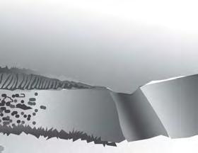
13 6.72 VEGETATIVE STREAMBANK STABILIZATION This practice standard has been adapted from the Natural Resource Conservation Service National Engineering Handbook, Part 654, Technical Supplement 14I, Streambank Soil Bioengineering. At publication this document was not listed online with older NRCS publications, but was available through NRCS edirectives at Land disturbing activity involving streams, wetlands or other waterbodies may also require permitting by the U.S. Army Corps of Engineers or the N.C. Division of Water Quality. Approval of an erosion and sedimentation control plan is conditioned upon the applicant s compliance with federal and State water quality laws, regulations, and rules. Additionally, a draft plan cannot be approved if implementation of the plan would result in a violation of rules adopted by the Environmental Management Commission to protect riparian buffers along surface waters. Care should be taken in selecting vegetative stabilization of streambanks, wetlands and riparian buffers to comply with permitting requirements of other agencies, as well as provide adequate ground cover. Stabilizing streambanks with natural vegetation has many advantages over hard armor linings. Compared to streams without vegetated banks, streams with well-stabilized vegetation on their banks have better water quality and fish and wildlife habitats. Vegetation is an extremely important component of biological and chemical health, as well as the stability of the system. Streambank soil bioengineering is defined as the use of live and dead plant materials in combination with natural and synthetic support materials for slope stabilization, erosion reduction, and vegetative establishment (Allen and Leech 1997). Streambank soil bioengineering uses plants as primary structural components to stabilize and reduce erosion on streambanks, rather than just for aesthetics. As a result of increased public appreciation of the environment, many Federal, state, and local governments, as well as grass roots organizations, are actively engaged in implementing soil bioengineering treatments to stabilize streambanks. Riparian planting zones Success of streambank soil bioengineering treatments depends on the initial establishment and long-term development of riparian plant species. It is important to note the location and types of existing vegetation in and adjacent to the project area. The elevation and lateral relationships to the stream can be described in terms of riparian planting zones. Proposed streambank soil bioengineering techniques should also be assessed and designed in terms of the location of the plants relative to the stream and water table. These riparian planting zones can be used to determine where riparian species should be planted in relation to the waterline during different periods of flow. Figure 6.72a illustrates an idealized depiction of riparian planting zones. Toe zone This zone is located below the average water elevation or baseflow. The cross-sectional area at this discharge often defines the limiting biologic condition for aquatic organisms. Typically, this is the zone of highest stress. It is vitally important to the success of any stabilization project that the toe is stabilized. Due to long inundation periods, this zone will rarely have any Rev. 5/
14 6 woody vegetation. Often riprap or another type of inert protection is required to stabilize this zone. Bank zone The bank zone is located between the average water elevation and the bankfull discharge elevation. While it is generally in a less erosive environment than the toe zone, it is potentially exposed to wet and dry cycles, ice scour, debris deposition, and freeze-thaw cycles. The bank zone is generally vegetated with early colonizing herbaceous species and flexible stemmed woody plants such as willow, dogwood, elderberry, and low shrubs. Sediment transport typically becomes an issue for flows in this zone, especially for alluvial channels. Bankfull channel elevation Bankfull stage is typically defined at a point where the width-to-depth ratio is at a minimum. Practitioners use other consistent morphological indices to aid in its identification. Often, the flow at the bankfull stage has a recurrence interval of 1.5 years. Due to the high velocities and frequent inundation, some high risk streambank soil bioengineering projects frequently incorporate hard structural elements, such as rock, below this elevation. Where there is a low tolerance for movement, many projects rely on inert or hard elements in this zone. Bankfull flow is often considered to be synonymous with channel-forming discharge in stable channels and is used in some channel classification systems, as well as for an initial determination of main channel dimensions, plan, and profile. In many situations, the channel velocity begins to approach a maximum at bankfull stage. In some cases, on wide, flat flood plains, channel velocity can drop as the stream overtops its bank and the flow spills onto the flood plain. In this situation, it may be appropriate to use the bankfull hydraulic conditions to assess stability and select and design streambank protection. However, when the flood plain is narrower or obstructed, channel velocities may continue to increase with rising stage. As a result, it may also be appropriate to use a discharge greater than bankfull discharge to select and design streambank protection treatments. Overbank zone This zone is located above the bankfull discharge elevation. This typically flat zone may be formed from sediment deposition. It is sporadically flooded, usually about every 2 to 5 years. Vegetation found in this zone is generally flood tolerant and may have a high percentage of hydrophytic plants. Shrubby willow with flexible stems, dogwoods, alder, birch, and others may be found in this zone. Larger willows, cottonwoods, and other trees may be found in the upper end of this zone. Transitional zone The transitional zone is located between the overbank elevation and the flood-prone elevation. This zone may only be inundated every 50 years. Therefore, it is not exposed to high velocities except during high-water events. Larger upland species predominate in this zone. Since it is infrequently flooded, the plants in this zone need not be especially flood tolerant. Upland zone This zone is found above the floodprone elevation. Erosion in this zone is typically due to overland water flow, wind erosion, improper farming practices, logging, development, overgrazing, and urbanization. Under natural conditions the upland zone is typically vegetated with upland species Rev. 5/08

15 Figure 6.72a Plants for soil bioengineering Consult local expertise and guidelines when selecting the appropriate plant material. Where possible, it is best to procure harvested cuttings from areas that are similar in their location, relative to the stream. Installation will be most successful where the soil, site, and species match a nearby stable site. Harvest three or more species from three to five different locations. Woody plants Adventitiously rooting woody riparian plant species are used in streambank soil bioengineering treatments because they have root primordia or root buds along the entire stem. When the stems are placed in contact with soil, they sprout roots. When the stem is in contact with the air, they sprout stems and leaves. This ability to root, independent of the orientation of a stem, is a reproductive strategy of riparian plants that has developed over time in response to flooding, high stream velocities, and streambank erosion. Many woody riparian plant species root easily from dormant live cuttings. They establish quickly and are fast-growing plants with extensive fibrous root systems. These plants are typically hardy pioneer species that can tolerate both inundation and drought conditions. The keystone species that meet these criteria are willows, cottonwoods, and shrub dogwoods. These traits allow their use in treatments such as fascines, brush mattress, brush layer, and pole cuttings. Typically, the most consistently successful rooting plants are the willow (Salix spp.). Data from projects nationwide indicate that shrub willows root successfully on average 40 to 100 percent of the time. Shrub dogwoods (Cornus spp.), on the other hand, are more variable in their rooting success, ranging from 10 to 90 percent, but more typically averaging in the 30 to 60 percent range. Rooting Rev. 5/
16 6 success of both willows and dogwoods can be affected by the timing of planting, age of the material used, handling and storage, installation procedures, and placement in the proper hydrologic regime on the streambank. Cottonwoods and poplars (Populus spp.) have also been used successfully in streambank soil bioengineering. However, typical riparian species such as birches (Betula spp.) and alders (Alnus spp.) do not root well from unrooted hardwood cuttings; therefore, they are not suitable for certain soil bioengineering techniques such as poles or live stakes. They are, however, useful as rooted plant stock for many soil bioengineering measures including hedgelayers, branch packing, cribwalls, vegetated reinforced soil slopes, and live siltation construction. Additionally, these and other species can be included in a riparian seed mix or installed as rooted plants as part of the stream and riparian restoration. In some cases, a pilot study will allow wise selection of some nonstandard plant materials by testing how effectively locally available genotypes are adapted to soil and hydrologic conditions on site. Limiting velocity and shear criterion The effects of the water current on the stability of any streambank protection treatment must be considered. This evaluation includes the full range of flow conditions that can be expected during the design life of the project. Two approaches that are commonly used to express the tolerances are allowable velocity and allowable shear stress. Flow in a natural channel is governed in part by boundary roughness, gradient, channel shape, obstructions, and downstream water level. If the project represents a sizable investment, it may be appropriate to use a computer model such as the U.S. Army Corps of Engineers (USACE) HEC RAS computer program to assess the hydraulic conditions. However, if a normal depth approximation is applicable, velocity can be estimated with Manning s equation. It is important to note that this estimate will be an average channel velocity. In some situations, the velocity along the outer bank curves may be considerably larger. The average shear stress exerted on a channel boundary can be estimated with the equation provided below, assuming the flow is steady, uniform, and two dimensional. = RSf where: = average boundary shear (lb/ft2) = specific weight of water (62.4 lb/ft3) R = hydraulic radius (A/P, but can be approximated as depth in wide channels) Sf = friction slope (can be approximated as bed slope) The local maximum shear can be up to 50 percent greater than the average shear in straight channels and larger along the outer banks of sinuous channels. Temporal maximums may also be 10 to 20 percent larger, as well. Recommendations for limiting velocity and shear vary widely Table 6.72a. Not all techniques presented in this technical supplement are noted in this table. However, the designer can compare techniques with similar attributes to those listed in the table to estimate the limiting shear. The designer should proceed cautiously and not rely too heavily on these values. Judgment and experience should be weighed with the use of this information. The recommendations in Table 6.72a were empirically determined and, therefore, are most applicable to the conditions in which they were derived. The recommendations must be Rev. 5/08
17 scrutinized and modified according to site-specific conditions such as duration of flow, soils, temperature, debris and ice load in the stream, plant species, as well as channel shape, slope and planform. Specific cautions are also noted in the table. However, there are anecdotal reports that mature and established practices can withstand larger forces than those indicated in Table 6.72a. Table 6.72a Compiled permissible shear stress levels for streambank soil bioengineering practices Permissible shear stress Permissible velocity Practice (lb/ft2)* (ft/s)* Live poles Initial: 0.5 to 2 Initial: 1 to 2.5 (Depends on the length of the poles and nature of the soil) Established: 2 to 5+ Established: 3 to 10 Live poles in woven coir TRM Initial: 2 to 2.5 Initial: 3 to 5 (Depends on installation and anchoring of coir) Established: 3 to 5+ Established: 3 to 10 Live poles in riprap (joint planting) Initial: 3+ Initial: 5 to 10+ (Depends on riprap stability) Established: 6 to 8+ Established: 12+ Live brush sills with rock Initial: 3+ Initial: 5 to 10+ (Depends on riprap stability) Established: 6+ Established: 12+ Brush mattress Initial: 0.4 to 4.2 Initial: 3 to 4 (Depends on soil conditions and anchoring) Established: 2.8 to 8+ Established: 10+ Live fascine Initial: 1.2 to 3.1 Initial: 5 to 8 (Very dependent on anchoring) Established: 1.4 to 3+ Established: 8 to 10+ Brush layer/branch packing Initial: 0.2 to 1 Initial: 2 to 4 (Depends on soil conditions) Established: 2.9 to 6+ Established: 10+ Live cribwall Initial: 2 to 4+ Initial: 3 to 6 (Depends on nature of the fill (rock or earth), Established: 5 to 6+ Established: 10 to 12 compaction and anchoring) Vegetated reinforced soil slopes (VRSS) Initial: 3 to 5 Initial: 4 to 9 (Depends on soil conditions and anchoring) Established: 7+ Established: 10+ Grass turf excellent stand Established: 3.2 Established: 3 to 8 (Depends on vegetation type and condition) Live brush wattle fence Initial: 0.2 to 2 Initial: 1 to 2.5 (Depends on soil conditions and depth of stakes) Established: 1.0 to 5+ Established: 3 to 10 Vertical bundles Initial: 1.2 to 3 Initial: 5 to 8 (Depends on bank conditions, anchoring, and vegetation) Established: 1.4 to 3+ Established: 6 to 10+ * (USDA NRCS 1996b; Hoag and Fripp 2002; Fischenich 2001; Gerstgrasser 1999; Nunnally and Sotir 1997; Gray and Sotir 1996; Schiechtl and Stern 1994; USACE 1997; Florineth 1982; Schoklitsch 1937) Rev. 5/

18 6 Streambank soil bioengineering Techniques Many types of streambank soil bioengineering treatments have been used throughout the country. A collection of techniques that are broadly applicable have been divided into sections that address the different bank zones. It is appropriate to modify these treatments to account for site-specific conditions, cost of materials, and material availability. Many variations of these techniques exist. Many of the techniques listed are often combined with other streambank soil bioengineering techniques or with harder, inert structures. Toe treatments Coir fascines This is a manufactured product also known as coir logs or coconut fiber rolls. Coir fascines consist of coconut husk fibers bound together in a cylindrical bundle by natural or synthetic netting and are manufactured in a variety of standard lengths, diameters, and fill densities for different energy environments. Coir fascines are flexible and can be fitted to the existing curvature of a streambank. They provide immediate toe protection and bank stabilization, while trapping sediment within the coir fascine, which encourages plant growth. Coir fascines are well suited for establishing herbaceous materials, and they can be prevegetated prior to installation. A key advantage of this method is the modularization and standardization of the materials that result in relatively predictable and reliable performance. A disadvantage of coir fascines is that they are expensive to purchase and ship. They require additional anchoring systems, which increases the initial costs and installation time. Figure 6.72b Coir log installation, NC Ecosystem Enhancement Program Materials are preferred for streambank stabilization work because they serve as a stable growing medium on which seeds and young plants can become established. This material provides some resistance to damage from ice flows, floating debris, and other impacts, and provides a reinforcing framework for vegetation until the coir filling decays, at which point the plants should be able to protect the banks. synthetic mesh is desirable for the knotted or braided mesh exterior of the coir fascine. Although coir mesh versions are available, the mesh frequently loses its strength before vegetation can become fully established, making the material vulnerable to failure. Therefore, coir mesh versions are typically used on sites with low stress levels. of 9 pounds per cubic foot. Where ice, debris, steep banks, and other stress factors are not a problem, lower density materials may offer a more costeffective alternative Rev. 5/08
19 in both larger and smaller sizes. with cable assemblies. Installation can be worked adequately for placement and anchoring. Planting into the coir fascine may be planned for later in a more desirable season, as needed. bank, where it was located prior to an erosion event, or in direct contact with the current bank profile. Typically, they are positioned so that the top of the coir fascine is located at the mean water level during the summer growing season. In most cases, this zone best supports herbaceous vegetation. Due to the distance from the plant to the soil, it is imperative that the coir fascine remain wet. species which, preferably, have been rooted in a coir fiber matrix to provide good frictional contact. addressed in the design. contact with the adjacent soil. Normally, this means a pair of stakes placed every 2 feet along the coir fascine, one on each side. In cold climates, earth anchors or rope tie-downs are necessary to prevent lifting of the coir fascine as ice forms. Always place wooden stakes between the cable or rope and the coir to keep the cable or rope from cutting clear through the coir fascine. Piercing a high-density coir fascine with stakes should be avoided. The stakes should be driven alongside the coir fascine. The coir fascine is secured by either tightly sandwiching the coir fascine between the stakes or by using ropes or cables to tie around the coir fascine. is most convenient to do while the coir fascines are still on dry land, laid out along the top of bank. Strong synthetic rope is used to stitch the ends together, with knots tied at frequent intervals to ensure a reliable connection. they must be placed together on the edges where they touch. One row of lacing is typically adequate to hold two tiers together, although two rows of lacing will result in a tighter contact between the tiers, which is useful at holding back concohesive soils. All tiers require appropriate staking or anchoring. may be inserted through the coir fascine itself, or 2-inch-diameter plugs may be inserted 6 inches on center along the length of the coir fascine. may be placed on the first (lower) coir fascine, prior to placing the next one above it. Fascines A fascine is a long bundle of live cuttings bound together into a rope or sausage-like bundles. The structure provides immediate protection for the toe. Since this is a surface treatment, it is important to avoid sites that will be too wet or too dry. The live cuttings eventually root and provide permanent reinforcement. Rev. 5/

20 6 Figure 6.72c Combining fascines and fabric Materials nongalvanized wire on soil conditions saw Installation harvested and fabricated. Leave side branches intact. feet. Vary the orientation of the cuttings. Use 8- to 10-foot bundles for ease of handling, and transport in a pickup bed. They can also be easily spliced together to create a fascine long enough to fit the particular project site. be 6 to 24 inches in diameter, depending on their application. bank. bed. The trench should be about a half to three-quarters the diameter of the bundle. directly through the bundle 3 feet on center. Allow the stake to protrude 2 inches above the top of the bundle. To improve depth of reinforcement and rooting, install live stakes (2 to 3 ft in length) just below (downslope) and in between the previously installed dead stout stakes, leaving 3 inches protruding from the finished ground elevation Rev. 5/08

21 with water to get around the inner stems of the bundle. Some of the bundle should remain exposed to sunlight to promote sprouting. Use material from the next upbank trench. It may be desirable to use erosion control fabric to hold the soil adjacent to and in between the fascine bundles, especially in wet climates. When using erosion control fabric between the fascine bundles, the fabric is first placed in the bottom of the trench, an inch of soil is placed on top and up the sides of the trench and erosion control fabric, and the fascine bundle is then placed in the trench and staked down. Note: Fascines can be oriented perpendicular to the streambank contours. This practice is often called the vertical bundle method. The primary difference between the construction of a vertical bundle and a fascine is that all of the cuttings in a vertical bundle are oriented so the cut ends are in the water. It is particularly applicable in areas where there is uncertainty in determining the water table. Bank treatments Live pole cuttings or live stakes Live pole cuttings are dormant stems, branches, or trunks of live, woody plant material inserted into the ground with the purpose of getting them to grow. Live stakes are generally shorter material that are also used as stakes to secure other soil bioengineering treatments such as fascines, brush mattresses, erosion control fabric, and coir fascines. However, the terms live stakes and live pole cuttings are often used interchangeably. Both live poles and live cuttings can be used as anchoring stakes. They are live material so they will also root and sprout. Live pole cuttings are 3 to 10 feet long, and 3/4 to 3 inches in diameter. These cuttings typically do not provide immediate reinforcement of soil layers, as they normally do not extend beyond a failure plane. Over time, they provide reinforcement to the soil mantle, as well as surface protection and roughness to the streambank and some control of internal seepage. They assist in quickly reestablishing riparian vegetation and cause sediment deposition in the treated area. Figure 6.72d Live cuttings installed in fabric Rev. 5/
22 6 Materials rebar Installation end to a 45-degree angle, or sharpen into a pointed end. The top end should be cut flat. At least two buds or bud scars should be present above the ground in the final installation, depending on the surrounding vegetation height. The live cuttings should be taller than the surrounding vegetation to ensure that they are not shaded. are harvested and fabricated. to the slope. The depth of the hole should be 2/3 to 3/4 the length of the live cutting. Make the hole diameter as close to the cutting s diameter as possible to obtain the best soil-to-stem contact. The hole should be deep enough to intercept the lowest water table of the year or a minimum of 2 feet. and-soil slurry mixture. Add soil around the cutting as the water percolates into the ground and the soil in suspension settles around the cutting. Another method is to tamp soil around the cutting with a rod. Throw a small amount of soil in the hole around the cutting and tamp it down to remove all air pockets. This is similar to installing a wooden fence post. blow hammer to tap the cutting into the ground. Insert the cutting at a 90- degree angle to the face of the slope. Ensure that the sharpened basal end is installed first. grid for most shrub species. Spacing depends on species, moisture, aspect, and soil. Joint plantings Joint plantings or vegetated riprap are cuttings of live, woody plant material inserted between the joints or voids of riprap and into the ground below the rock. Joint planting cuttings are 30 to 48 inches long, and from 3/4 to 2 inches in diameter. These live cuttings typically do not provide immediate reinforcement of soil layers, as they normally do not extend beyond the failure plane. The live cuttings are intended to root and develop top growth providing several adjunctive benefits to the riprap. Over time, these installations provide reinforcement to the soil on which the riprap has been placed, as well as providing roughness (top growth) that typically causes sediment deposition in the treated area. Some control of internal seepage is also provided. These joint planting installations assist in quickly reestablishing riparian vegetation. Joint plantings are frequently used on the lower part of the bank. Materials long. They should be long enough so that at least 1 foot of the cutting will extend into the ground below the riprap. saw, loppers, and rebar Rev. 5/08

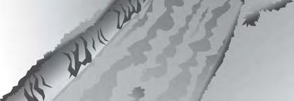
23 Installation the basal end to a 45-degree angle, or sharpen to a point. The top end should be cut flat. At least two buds or bud scars should be present above the ground in the final installation, depending on the surrounding vegetation height. The live cuttings should be taller than the surrounding vegetation to ensure that they are not shaded. harvested and fabricated. steel stinger can also be used. Carefully extrude the rebar and tamp in the joint planting stem. Insert the basal end first. water and soil slurry mixture. grid. Spacing depends on species, moisture, aspect, and soil characteristics. Brush mattress A brush mattress is a layer of live cuttings placed flat against the sloped face of the bank. Dead stout stakes and string are used to anchor the cutting material to the bank. This measure is often constructed using a fascine, joint planting, or riprap at the toe, with live cuttings in the upper mattress area. The branches provide immediate protection from parallel streamflow. The cuttings are expected to root into the entire bank face and provide surface reinforcement to the soil. Figure 6.72e (a) Brush mattress being installed; (b) Brush mattress after one growing season Materials 2 feet taller than the bank face. This will allow the basal ends to be placed in or at the edge of the water. Up to 20 percent of the cuttings can be dead material to add bulk. texture wire and machine to shape the bank Rev. 5/
24 6 Installation harvested. Leave side branches intact. stout stakes. the slope to the bottom of the slope is typically 4 to 20 feet. Excavate a 1-footwide and 8- to 12-inch-deep trench along the toe. prepared bank. Space the installation of the dead stout stakes on a grid that is 1.5 to 3 foot square. Start the lowest row of dead stout stakes below bankfull width or a fourth of the height of the bank. The tops of the dead stout stakes should extend above the ground 6 to 9 inches. Live cuttings may also be mixed with the dead stout stakes, and tamped in between to add deeper initial rooting. However, the live cuttings cannot generally be driven-in as securely as the dead stout stakes and should not be relied upon solely for anchoring the brush mattress. cuttings are installed into the trench with the growing tips oriented upbank. The live cuttings side branches should be retained and should overlap in a slight crisscross pattern. Depending on the size of the branches, approximately 8 to 15 branches are installed per linear foot of bank. brush mattress to ensure the basal ends of the live cuttings are pressed against the bank. manila, sisal, or prestretched cotton twine in a diamond pattern between the dead stout stakes. Short lengths of tying material are preferred over long lengths. In the event of a failure, only a small portion of the treatment would be compromised if short lengths are used. Otherwise, there are risks of losing larger portions of the project if long lengths of tying material are used to anchor the cuttings to the dead stout stakes. further into the bank to firmly secure the live cuttings to the bank face. This improves the soil-to-stem contact. the bottom half of the cuttings is covered with a 3-4 inch layer of soil. the lateral buds for more rapid root and stem sprouting. Top of bank/flood plain treatments Brush trench A brush trench is a row of live cuttings that is inserted into a trench along the top of an eroding streambank parallel to the stream (Figure 6.72e). The live cuttings form a fence that filters runoff and reduces the likelihood of rilling. The live cuttings eventually root and provide a permanent living structure. Brush trenches are often used to supplement other soil bioengineering treatments Rev. 5/08

25 Materials Figure 6.72e (a) Brush trench after installation; (b) 1 year later Installation are harvested. Leave the side branches intact. It is important to select lowgrowing species that will remain supple. trench. a low berm along the top of the bank and directing the flow to a stable outfall away from the bank. should be no less than 1 foot back from the top of the bank so that it does not weaken the bank. mat. Make sure that the basal ends touch the bottom of the trench. Install 8 to 15 live cuttings per linear foot of trench. The branches protruding from the top of the trench should be taller than the height of competing vegetation. stem contact. All gaps between the plant materials within the trench should be filled with soil. is completed, water the entire area. Supplemental irrigation may also be required as the vegetation becomes established. Monitoring and maintenance While soil bioengineering projects tend to be self-renewing and grow stronger with time, project areas require periodic monitoring and maintenance, particularly during the establishment stage. Maintenance is especially important on highly erosive sites. Maintenance could include removal of debris and elimination of invasive or undesirable species, as well as replanting vegetation in spot areas. The success of a soil bioengineering streambank Rev. 5/
26 6 stabilization project obviously depends on the establishment and growth of the vegetative component. Allen and Leach (1997) noted that it is important to monitor soil bioengineering projects after project completion to assure plant survival and development. For example, supplemental irrigation may be necessary for exceptionally dry conditions. A fungicide or insecticide may need to be applied if insects or disease are an issue. Beaver, geese, livestock, deer, and other herbivores may also eat the plants in a streambank soil bioengineering project. The loss of a predetermined percentage of the planting may be used to trigger a requirement for remedial planting. If a moderate storm occurs before establishment of the vegetative component of a streambank soil bioengineering project, there is a potential for significant damage to the project. In fact, depending on the nature of the stream and the project, this damage may be severe enough that the vegetative component of the project may not recover. Therefore, it is recommended that most soil bioengineering projects be inspected after moderate flows, as well as on a periodic basis. These inspections are often enough to determine if remedial action will be necessary. One of the most common problems identified with newly installed bioengineered treatments is herbivory, or consumption by plant-eating animals. At times, Canada geese or muskrats may decimate a new herbaceous planting, or beaver may trim every shrub and tree sprout down to ground level. This comes as a shock and disappointment when it occurs, especially after completing a project or even after a robust initial growing phase. Most woody plantings rebound quickly from such impacts, and therefore, can be considered indications of beneficial habitat use. Many herbaceous plantings also rebound well, but if unrooted or repeatedly grazed down to the ground, the damage can be permanent. If this is a possibility, it may be advisable to provide a measure in the plans for inspection and replacement of lost material. Conclusion Streambank soil bioengineering is the use of living and nonliving herbaceous and woody plant materials in combination with natural or synthetic support materials for slope stabilization, erosion reduction, and vegetative establishment. This technique has a rich history and uses plants and sometimes inert material to increase the strength and structure of the soil. The use of streambank soil bioengineering treatments is increasing in popularity for a number of reasons: improved aesthetics, increased scrutiny by regulatory agencies, improved water quality benefits, restored fish and wildlife habitat, and decreased costs. The long-term goal of many streambank soil bioengineering stabilization projects is to mimic natural conditions within a natural or newly altered regime. Unaltered channels in their natural environments can be expected to move and erode during large storms. Therefore, where the goal is to allow the system to remain natural, the bank will likely not be static, and periodic bank erosion should be expected. This condition can be contrasted to more urban situations where the proposed conditions of the channel typically do not allow for bank erosion. In these cases, the selected streambank soil bioengineering methods incorporate hard or inert elements that can handle higher velocity flows and to limit the flexibility of the protected bank. Many types of soil bioengineering treatments can be used to stabilize streambanks and can withstand varying shear limits and velocities. Streambank soil bioengineering treatments are a viable alternative to hard structures, as long as the risks are clearly understood and planned for. Understanding the riparian planting zones is particularly important to ensure that the vegetation is planted in the right zone Rev. 5/08
27 6.73 STRUCTURAL STREAMBANK STABILIZATION This practice standard has been adapted from the Natural Resource Conservation Service National Engineering Handbook, Part 654, Technical Supplement 14K, Streambank Armor Protection with Stone Structures. At publication this document was not listed online with older NRCS publications, but was available through NRCS edirectives at aspx?id=3491 Land disturbing activity involving streams, wetlands or other waterbodies may also require permitting by the U.S. Army Corps of Engineers of the N.C. Division of Water Quality. Approval of an erosion and sedimentation control plan is conditioned upon the applicant s compliance with federal and State water quality laws, regulations, and rules. Additionally, a draft plan cannot be approved if implementation of the plan would result in a violation of rules adopted by the Environmental Management Commission to protect riparian buffers along surface waters. Care should be taken in selecting structural stabilization of streambanks to comply with permitting requirements of other agencies, as well as provide adequate ground cover. Introduction Stone has long been used to provide immediate and permanent stream and river protection. It continues to be a major component in many of the newer and more ecologically friendly projects, as well. Many situations still require rock riprap to some degree. Rock riprap measures have a great attraction as a material of choice for emergency type programs, where quick response and immediate effectiveness are critical. Rock riprap is needed for many streambank stabilization designs, especially where requirements for slope stability are restrictive, such as in urban areas. It is one of the most effective protection measures at the toe of an eroding or unstable slope. The toe area generally is the most critical concern in any bank protection measure. The primary advantages of stone over vegetative approaches are the immediate effectiveness of the measure with little to no establishment period. The use of stone may offer protection against stream velocities that exceed performance criteria for vegetative measures. Stone considerations Not all rocks are created equal. A variety of important stone design characteristics and requirements exist that must be accounted for to successfully use rock in the stream. Stone size The stone used in a project, whether it is part of a combined structure or used as a traditional riprap revetment, must be large enough to resist the forces of the streamflow during the design storm. A stone-sizing technique appropriate for the intended use must also be selected. Many established and tested techniques are available for sizing stone. Most techniques use an estimate of the stream s energy that the rock will need to resist, so some hydraulic analysis is generally required. Stone shape Some methods use different dimensions to characterize stone size. The critical dimension is the minimum sieve size through which the stone will pass. Some techniques assume that riprap is the shape of a sphere, cube, or even a football Rev. 5/
28 6 shape (prolate spheroid). To avoid the use of thin, platy rock, neither the breadth nor the thickness of individual stones is less than a third of its length. The U.S. Department of Agriculture (USDA) Natural Resources Conservation Service (NRCS) specifies riprap to be a spheroid three times as long as it is thick (L/B = 3). Note that the shape of most riprap can be represented as the average between a sphere and a cube. An equation for an equivalent diameter of riprap shaped between a cube and a sphere is: where: W = weight of the stone, lb = density of the stone, approx. 165 lb/ft3, D = equivalent diameter, ft This relationship may be helpful if a conversion between size and weight is necessary for angular riprap with this shape. Riprap should be angular to subangular in shape. Field experience has shown that both angular (crushed limestone) and rounded rock (river stones) can be used for riprap protection with equal success, but shape differences do require design adjustments. Rounded rock does not interlock as well as angular rock. Generally, rounded rock must be 25 to 40 percent larger or more in diameter than angular rock to be stable at the same discharge. Stone gradation Stone gradation influences resistance to erosion. The gradation is often, but not always, considered by the technique used to determine the stone size. For most applications, the stone should be reasonably well graded (sizes are well distributed) from the minimum size to the maximum size. Onsite rock material may be used for rock riprap when it has the desired size, gradation, and quality. A well-graded distribution will have a wider range of rock sizes to fill the void spaces in the rock matrix. The stone gradation influences the design and even the need for a filter layer or geotextile. Further information on the design, use, and application of geotextiles is provided later in this section. Design considerations Stabilizing channel banks is a complex problem and does not always lend itself to precise design. The success of a given installation depends on the judgment, experience, and skill of the planners, designers, technicians, and installers. Several important issues that must be considered for the successful design of projects that depend on the rock performance are briefly described. Filter layer Where stone is placed against a bank that is composed of fine-grained or loose alluvium, a filter layer or bedding is often used. This filter layer prevents the smaller grained particles from being lost through the interstitial spaces of the riprap material, while allowing seepage from the banks to pass. This filter layer needs to be appropriately designed to protect the in-place bank material and remain beneath the designed stone or riprap. Therefore, the gradation is based in part of the gradation of the riprap layer and the bank material. The filter layer typically consists of a geosynthetic layer or an 8-inch-thick layer of sand or gravel Rev. 5/08
29 Bank slope Many stone sizing techniques also require information about the bank slope. In addition, a geotechnical embankment analysis may impose a limit on the bank slope. The recommended maximum slope for most riprap placement is 2H:1V. Short sections of slopes at 1.5H:1V are sometimes unavoidable, but are not desirable. Most rock cannot be stacked on a bank steeper than 1.5H:1V and remain there permanently. For riprap placement of 1.5H:1V and steeper, grouting of the rock to keep it in place must be strongly considered. Alternative measures, such as gabion baskets, are well suited to steep banks. Also, flatter slopes increase the opportunity for vegetation establishment. Height Stone should extend up the bank to a point where the existing vegetation or other proposed treatment can resist the forces of the water during the design event. In a soil bioengineering project, a stone revetment typically does not exceed the elevation of the level of the channel-forming flow event. However, there are exceptions where it is advisable to extend the riprap to the top of the bank. Thickness Different stone-sizing techniques may have different assumptions concerning the blanket thickness. The thickness of the placed rock should equal or exceed the diameter of the largest rock size in the gradation. In practice, this thickness will be one and a half to three times the median rock diameter (D50). A typical minimum thickness is the greater of 0.75 times the D100 or one and a half times the D50. Scour Toe scour is the most frequent cause of failure in streambank armor protection projects. Scour can be long term, general, and local. The greatest scour depths generally occur on the outside and lower portion of curves. Scour depths may increase immediately below and adjacent to structural protection due to the higher velocity section of a stream adjacent to the relatively smooth structure surface. This may undermine the structure and result in failure. Common methods for providing toe protection are: fill any expected scour to a hard point the bank protection measures down to a point below the probable maximum depth of the anticipated bed scour. A typical rule of thumb for a minimum key-in depth is one and a half times the riprap thickness or a minimum of 2 feet below the existing streambed. This practical solution generally gives good protection against undermining. Placement of rock Rock should be placed from the lowest to the highest elevation to allow gravitational forces to minimize void spaces and help lock the rock matrix together. It is important that riprap be placed at full-course thickness in one operation. Final finished grade of the slope should be achieved as the material is placed. Care should be taken not to segregate or group material sizes together during placement. Allowing the stone to be pushed or rolled downslope will cause stone size segregation. See ASTM D6825 on placement of riprap revetments. An advantage of using riprap structures is that materials are generally readily available, and contractors with appropriate equipment and Rev. 5/
30 6 experience can be found. However, careful consideration should be given early in the design process to the stone installation method. Two commonly employed installation methods are described below. Dumped rock riprap This method of protection may be necessary where access to the streambed is limited or for emergency situations. Streambank work using dumped rock requires a source of low-cost rock. Access roads must be available near the stream channel, so that rock can be hauled to the streambank and either dumped over the bank or along the edge. If the job requires large quantities of rock, the operation must be set up to accommodate regular deliveries to the job site. In some cases, the banks may be too weak to support a loaded truck, thereby preventing dumping of rock directly over the streambank. In such cases, the rock may be dumped as close to the edge as possible and pushed over the edge with a bulldozer or front-end loader. Larger rock should be placed at the bottom of the revetment work to provide a stable toe section. The use of a front-end loader may be useful to select rock by size and push it over the bank. This type of placement usually results in a poor gradation of material due to material segregation, requiring more volume to make up for the lack of gradation. While this type of bank protection requires more stone per square yard of bank protection than machine placed riprap, it generally requires less labor and equipment operating hours. Machine-placed riprap This type of riprap is placed using a track-mounted backhoe or a power crane with a clam shell or orange peel bucket. The riprap is placed on a prepared slope of the streambank to a minimum design thickness of 12 to 18 inches. The larger stones are placed in a toe trench at the base of the slope. This method requires an experienced equipment operator to achieve uniform and proper placement. The toe or scour trench can be dug with the backhoe or clam shell as the machine moves along the slope. The machine can do the backfilling with rock in the same manner. The bank sloping or grading generally is accomplished with a backhoe or sometimes a Gradall. If a power crane is used, a dragline bucket must be used with the crane for slope grading. A perforated dragline bucket works best because it allows excess water to drain from the bucket. Appropriate bedding and/or geotextile can be installed after the grading and slope preparation are completed. The primary function of these materials is for filtration to prevent movement of soil base materials through the rock riprap. Bedding is normally placed by dump truck and spread to the desired thickness with a backhoe bucket, a front-end loader, or a small dozer. Geotextile must be placed by hand, secured in place as recommended by the manufacturer, consistent with site specifications. It is important that the geotextile be placed in intimate contact with the base to preclude voids beneath the geotextile. Under larger stone, a coarse bedding may be placed on the geotextile to assure that the geotextile stays in contact with the subbase. In some locations, geotextiles may also be used as a reinforcement in very soft foundation conditions. As previously noted, there will also be situations where the banks may have sufficient gravel content, so that neither bedding nor geotextiles are needed. Riprap should be placed to provide a reasonably wellgraded and dense mass of rock with a minimum of voids and with the final surface meeting the specified lines and grades. The larger stones should be placed in the toe trench or well distributed in the revetment. The finished stone protection should be consolidated by the backhoe bucket or other acceptable means so that the surface is free from holes, noticeable projections, and clusters or pockets of only small or only large stones. Riprap placement should begin at the toe trench and progress up the slope maintaining the desired rock placement thickness as the work proceeds. After the toe trench Rev. 5/08
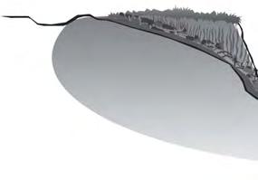
31 has been filled to the original stream bottom level, the operator should build a wall or leading edge with the riprap, which is the full layer thickness. That thickness should be maintained throughout the placement of the riprap. The wall should be maintained at about a 45-degree angle from a transverse line down the slope, as the placement progresses from the initial starting point at the streambed and progresses up and across the slope (fig. TS14K 2). Riprap rock should be handled and placed to the full layer thickness in one operation so that segregation is minimized and bedding or geotextile materials used under the riprap are not disturbed after the initial rock placement. Adding rock to the slope or removing it after the initial placement is not practical and generally produces unsatisfactory results. Dumping stone from the top and rolling it into place should also be avoided. This type of operation causes segregation and defeats the purpose of a rock gradation. Running on the riprap slope with track equipment, such as a bulldozer or rubber tire mounted front end loader, should also be avoided. It can damage the rock mass already in place. This operation can also tear the geotextile or damage the bedding by displacing material throughout the rock course. Tamping of the rock with the backhoe bucket can sometimes be used effectively to even up the surface appearance of riprap placement and further consolidate the rock course. It is advisable to have a test section when riprap is being placed over geotextile to check for geotextile puncturing. After the riprap is placed, it is removed, and the geotextile is evaluated. Figure 6.73a Typical riprap section Treatment of high banks The application of rock riprap protection on streambanks that are too high to be practically sloped can be accomplished using the following two methods: Embankment bench method The embankment bench method provides a reasonable approach to stabilize steep banks with little or no disturbance at the top of the slope and minimal disturbance to the streambed. The method also lends itself to an appropriate blend of structural, soil bioengineering, and vegetative stabilization treatments. This method, or some variation of it, is the most practical and preferred method of treating high, eroding streambanks. The embankment bench method involves Rev. 5/
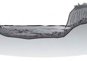
32 6 the placement of a gravel bench along the base of the eroding bank (Figure 6.73b). The elevation of the bench should be set no lower than the height of the opposite bank and, where practicable, 1 to 2 feet higher. This gravel bench provides drainage and protection at the base of the bank and a stable fill to support the structural toe protection. It also provides a working space for the equipment to place the toe protection, which is most often rock riprap or a combination of riprap and soil bioengineering practice. The embankment bench method requires that the convex side (low bank) of the channel be shaped by excavation of channel bed materials, normally bar removal, to compensate for the reduction in area taken by the bench projection. Offsite materials could be used for the bench in lieu of channel bed materials, but costs would be higher, and the resultant channel restriction could endanger the project. The high bank is generally left in its natural state and appropriately vegetated to assist stability. Some sloughing of the bank onto the prepared bench may occur before a good vegetative cover is established. Willows and other soil bioengineering materials can be established on the bench to help stabilize the toe of the bank and provide vegetative cover. By joint planting in the rock or by sediment accumulation and volunteer vegetation, the bench often can become a self-sustaining solution. Excavated bench method The excavated bench method (Figure 6.73c) is used in situations similar to the embankment bench. The excavated bench method does not require the gravel fill material or enlarging of the channel to compensate for the encroachment of the bench area. Instead, it involves shaping the upper half or more of the high bank to allow the formation of a bench to stabilize the toe of the slope. This is accomplished in a manner which leaves the upper part of the excavated slope at least in no worse shape than it was before the excavation. This solution is rarely practical, but may be necessary in cases where stream access is restricted or not allowed. It may also be a solution on lower banks where the excavation quantity is relatively small. Figure 6.73b Embankment bench method Rev. 5/08
33 Surface flow protection The damage to high banks is often exacerbated by surface runoff. If this is not treated, any protection at the toe may be damaged. High banks subject to damage by surface water flow can be protected by using diversion ditches constructed above the top slope of the bank. Water from active seepage in the high banks should be collected by interceptor drainage and conveyed to a safe outlet. Trees or other vegetative materials in a buffer strip along the top of the bank can be used to help control the active seepage by plant uptake and transpiration. Some soil bioengineering designs can also include ancillary drainage as a function. Figure 6.73c Excavated bench method Wire mesh gabions Gabions offer important advantages for bank protection. They can provide vertical protection in high-energy environments where construction area is restricted. Gabions can also be a more affordable alternative, especially where rock of the needed size for riprap is unavailable. Gabion wire mesh baskets can be used to stabilize streambank toes and entire slopes. Gabions can also be compatible with many soil bioengineering practices. Gabions come in two basic types: woven wire mesh and welded wire mesh. Woven wire mesh is a double-twisted, hexagonal mesh consisting of two wires twisted together in two 180-degree turns. Welded wire mesh has a uniform square or rectangular pattern and a resistance weld at each intersection. Within these two types there are two styles of gabions: gabion baskets and gabion mattresses. Baskets are 12 inches or more in height, while mattresses typically range from 5 to 12 inches in height. Gabion baskets can be particularly effective for toe stabilization on problem slopes. They provide the size and weight to stay in place, with the further advantage of being tied together as a unit. Baskets can be installed in multiple rows to increase stability and provide a foundation for other measures above them. Gabion mattresses are best suited for revetment type installations, channel linings, and waterways. They may also be used for basket foundations and scour aprons. All baskets and mattresses are of galvanized wire for corrosion protection. If the baskets are to be installed where abrasion from stream sediments is likely, PVC coated material should be used. PVC coating adds significantly to the durability and longevity of the gabion installation. This coating provides longterm benefits for a relatively small increase in material costs. It is important to use good quality rock of the proper size for gabion installation (Table 6.73a). Additional guidance on quality and sizing of rock can be found in ASTM Many manufacturers of gabions also provide guidance on the design and construction of their products. Rev. 5/
 Predominant Minimum rock Maximum rock Gabion rock size dimension dimension (in) (in) (in) 12-, 18-, 4 to 8 4 9 or 36-in basket 6-, 9-, 3 to 6 3 7 or")
34 6 Table 6.73a Specified rock sizes for gabions (from CS#64) Predominant Minimum rock Maximum rock Gabion rock size dimension dimension (in) (in) (in) 12-, 18-, 4 to or 36-in basket 6-, 9-, 3 to or 12-in mattress Gabions can be delivered to the work site in a roll and in panels and can be partially or fully assembled. Assembly generally must be accomplished at the work site. Important in all aspects of assembly are thesizing, bracing, and stretching of the baskets or mattresses. Assembly and installation procedures are well covered in NRCS National Construction Specification (CS) #64 (USDA NRCS 2005). Details for assembly and placement of double-twisted, wire mesh gabions can also be found in ASTM D7014. Important considerations in gabion placement are: placement ensuring alignment, avoiding bulges, and providing a compact mass. in any cell does not exceed the depth of the stone in any adjoining cell by more than 12 inches. by hand to achieve a neat and uniform appearance (Figure 6.73d). The tops of gabions will also require some hand work to make them level and full prior to closing and fastening the basket lids. It is important that the gabion basket or mattress is full and the lids fit tightly. Appropriate tools need to be used in this operation and care taken not to damage the lids by heavy prying. Various types of fasteners and lacing are used to assemble and secure gabion baskets and mattresses. The manufacturer s recommendations should be followed along with the applicable provisions in CS #64. Figure 6.73d Gabions showing a neat, compact, placement of stone with a uniform appearance Figure 6.73e Vegetated gabions under construction Rev. 5/08
35 Vegetated gabion In some locations, traditional gabions may be unacceptable from either an aesthetic or ecological perspective. A modification to traditional gabion protection that may satisfy these concerns is the vegetated gabion. A vegetated gabion incorporates topsoil into the void spaces of the gabion. The resulting gabion volume consists of 30 to 40 percent soil that allows root propagation between the stones. The resulting structure is interlocked with stone, wire, and roots (Figure 6.73e). Conclusion Many restoration designs require the use of rock in the stream. Riprap is one of the most effective protection measures at the toe of an eroding or unstable slope. Rock use has distinct advantages in terms of accepted design techniques and established contracting and construction procedures. In addition, many innovative bank stabilization and habitat enhancement projects use stone to perform important functions. Rock does present some drawbacks concerning cost, aesthetics, and ecological and geomorphic impacts. The challenge is to integrate more vegetative and geomorphic solutions without materially increasing the exposure time and risk of failure and meeting the goals of the project. This approach produces a long-term solution that will be complementary to the natural environment and will be more self-sustaining. Rev. 5/
36
37 6.74 BUFFER ZONES Buffer zone means the strip of land adjacent to a lake or natural water course (stream, river, swamp, canal, estuary, etc.). Buffer zones are used to reduce the impact of upland pollution by, Protective buffers should be used for, Tr). To determine a North As stated in the Sedimentation Pollution Control Act of 1973 (As Amended through 2005) of construction or improvement to land shall be permitted in proximity to a the duration of said disturbance would be temporary and the extent of said over, or under a lake or natural watercourse shall minimize the extent and duration of disruption of the stream channel. Rev. 6/


38 6 Width is a very important consideration in the overall effectiveness of buffers. Visible sediment collected within Figure 6.74a Guidance for Determining Width of Undisturbed Vegetation Zones Rev. 6/06
Biotechnical streambank stabilization
 Traditional streambank stabilization Biotechnical streambank stabilization Channelization alters: shape pattern slope bed morphology cover Ecological effects: loss of riparian habitat loss of fish habitat
Bio-Engineering Techniques to Revegetate Streambanks
 Bio-Engineering Techniques to Revegetate Streambanks DORMANT CUTTINGS Dormant cuttings are harvested from living woody plants. The cuttings are prepared from branches of woody plants when the plant is
STREAM ALTERATION PRACTICES
 STREAM ALTERATION PRACTICES Stream Diversion Channel SDC DEFINITION A temporary channel constructed to convey stream flow around in-stream construction. PURPOSE Stream diversion channels are used to allow
VEGETATED SLOPE STABILIZATION DESCRIPTION APPLICABILITY. Advantages
 4.2-d VEGETATED SLOPE STABILIZATION Alternative Names: Willow Wattles, Live Bundles, Fascines, Live Staking, Joint Planting, Branch Packing, Brush Layering, and Brush Matting DESCRIPTION Vegetated slope
HYDRAULIC DESIGN involves several basic
 Chapter 6 Tools for Hydr draulic and Road Design HYDRAULIC DESIGN involves several basic concepts that must be considered to build successful projects with a minimum risk of failure (Photo 6.1). Use of
Soil bioengineering and ecological
 Soil bioengineering and ecological systems Techniques Click to proceed... Copyright 2001 Maccaferri Inc. All rights reserved. All reproduction, including photocopy, film and microfilm, is forbidden. Release
Department of Agriculture. Conservation Service. United States. Natural Resources REVISED 8/26/16
 GENERAL NOTES: SYMBOL LEGEND 1. All work shall comply with the constriction specifications, drawings, project-specific quality assurance plan and other contract requirements. 2. All notes on the drawings
Stream Bank Erosion: Soil Bioengineering Solutions
 Stream Bank Erosion: Soil Bioengineering Solutions The principal causes of streambank erosion can be classed as geologic, climatic, vegetative, and hydraulic. These causes may act independently, but normally
Banking on Natural Fibers Products made from coir and jute play a key role in stabilizing a restored stream for a commercial stream mitigation bank.
 Banking on Natural Fibers Products made from coir and jute play a key role in stabilizing a restored stream for a commercial stream mitigation bank. By Greg Northcutt When White Creek Mitigation, LLC,
HOW TO CONTROL STREAMBANK EROSION
 6 HOW TO CONTROL STREAMBANK EROSION Prepared by the Iowa Department of Natural Resources In cooperation with the Natural Resources Conservation Service, U.S. DEPARTMENT OF AGRICULTURE 2006 The 1984 printing
Coir Block System (fabric attached coir block) add New Dimension to Streambank Stabilization Projects
 add New Dimension to Streambank Stabilization Projects") Coir Block System (fabric attached coir block) add New Dimension to Streambank Stabilization Projects Using geotextiles to confine soil in lifts between layers of live plants has become an increasingly
Coir Block System (fabric attached coir block) add New Dimension to Streambank Stabilization Projects Using geotextiles to confine soil in lifts between layers of live plants has become an increasingly
Guidelines for Streambank Protection
 PDHonline Course C187 (3 PDH) Guidelines for Streambank Protection Instructor: John Poullain, PE 2012 PDH Online PDH Center 5272 Meadow Estates Drive Fairfax, VA 22030-6658 Phone & Fax: 703-988-0088 www.pdhonline.org
USING PLANTS TO STABILIZE STREAM BANKS
 USING PLANTS TO STABILIZE STREAM BANKS This handout is intended to provide you with a general orientation to the three most common and practicable soil-bioengineering techniques. In a number of situations,
Guidelines for Installing Rolled Erosion Control Products in Slope, Channel and Shoreline Applications Laurie Honnigford
 Guidelines for Installing Rolled Erosion Control Products in Slope, Channel and Shoreline Applications Laurie Honnigford Soil erosion is evident in so many situations and the environmental impact can be
Low Gradient Velocity Control Short Term Steep Gradient [1] Channel Lining Medium-Long Term Outlet Control Soil Treatment Permanent
![Low Gradient Velocity Control Short Term Steep Gradient [1] Channel Lining Medium-Long Term Outlet Control Soil Treatment Permanent](/thumbs/77/74849271.jpg "Low Gradient Velocity Control Short Term Steep Gradient [1] Channel Lining Medium-Long Term Outlet Control Soil Treatment Permanent") Grass Linings DRAINAGE CONTROL TECHNIQUE Low Gradient Velocity Control Short Term Steep Gradient [1] Channel Lining Medium-Long Term Outlet Control Soil Treatment Permanent [1] May be used on short, steep
Grass Linings DRAINAGE CONTROL TECHNIQUE Low Gradient Velocity Control Short Term Steep Gradient [1] Channel Lining Medium-Long Term Outlet Control Soil Treatment Permanent [1] May be used on short, steep
CHAPTER 5. Soil Bioengineering Techniques
 CHAPTER 5 Soil Bioengineering Techniques Soil bioengineering is an applied science that combines the use of engineering design principles with biological and ecological concepts to construct and assure
Streambank Protection (SP)
") Streambank Protection (SP) Practice Description Streambank protection is the stabilization of the side slopes of a stream. Streambank protection can be vegetative, structural, or a combined method (bioengineering)
Streambank Protection (SP) Practice Description Streambank protection is the stabilization of the side slopes of a stream. Streambank protection can be vegetative, structural, or a combined method (bioengineering)
DITCH BANK STABILIZATION TECHNIQUES
 onstructed Ditch Drainage anagement Guide - No. 0 in series Order No. 5.0- December 00 DITH BANK STABILIZATION TEHNIQUES It is important to maintain ditches using practices that ensure ditch banks remain
SECTION SOIL BIOENGINEERING OR SHORELINE STABILIZATION
 SECTION 32 93 43 SOIL BIOENGINEERING OR SHORELINE STABILIZATION PART 1 GENERAL 1.01 SECTION INCLUDES A. CONTRACTOR shall furnish all labor, materials, supplies, equipment, tools and transportation; perform
Alternate Green Stream Bank Stabilization Methods
 U.S. Army Corps of Engineers Philadelphia/Baltimore Districts Alternate Green Stream Bank Stabilization Methods Wissahickon Creek, Tannery Run and Rose Valley Creek Bo-Rit Asbestos Site Ambler, Pennsylvania
Urban Conservation Practice Physical Effects ESTABLISHMENT, GROWTH, AND HARVEST NUTRIENT MANAGEMENT
 NOT WELL 800 - Urban Stormwater Wetlands A constructed system of shallow pools that create growing conditions for wetland plants to lessen the impacts of stormwater quality and quantity in urban areas.
EROSION & SEDIMENT CONTROL
 EROSION & SEDIMENT CONTROL 1 EROSION & SEDIMENT CONTROL Effective Soil & Water Protection Whether you want to prevent soil erosion caused by rain, water and wind, or protect waterways from inevitable build
SECTION 6. Routine Maintenance Activity Details
 SECTION 6 Routine Maintenance Activity Details 80. DEBRIS REMOVAL When Deadfall, and other objects, such as shopping carts, tires, appliances, and mattresses have accumulated in the drain. Why To prevent
Lake Shoreline Stabilization Techniques
 Environment and Sustainable Resource Development Lake Shoreline Stabilization Techniques Compliance Assurance / Operations Central Region Suite #1, 250 Diamond Avenue Box 4240 Spruce Grove, Alberta T7X
Live Stake and Joint Planting for Streambank Erosion Control
 Live Stake and Joint Planting for Streambank Erosion Control by Robbin B. Sotir and J. Craig Fischenich November 2007 Complexity Environmental Value Cost Low Moderate High Low Moderate High Low Moderate
Town of Essex Small Site Erosion Control Guide
 Town of Essex Small Site Erosion Control Guide Why do we need to protect against erosion? Water Quality: Erosion and the transport of sediment and pollutants impacts the water quality of nearby streams
PERMANENT SEEDING. Overview of Sedimentation and Erosion Control Practices. Practice no. 6.11
 Overview of Sedimentation and Erosion Control Practices Practice no. 6.11 PERMANENT SEEDING Permanent vegetation controls erosion by physically protecting a bare soil surface from raindrop impact, flowing
Applications of Coir Fibre Products in Environmental Erosion & Sediment Control and Restoration
 Applications of Coir Fibre Products in Environmental Erosion & Sediment Control and Restoration Calista R. Santha, Ph.D. Lanka Santha, P.E. RoLanka International, Inc. Stockbridge, GA, USA Coir Fibre Abundant,
Technical Supplement 14D. Geosynthetics in Stream Restoration. (210 VI NEH, August 2007)
") Technical Supplement 14D (210 VI NEH, August 2007) Issued August 2007 Cover photo: Inert or manmade materials can be used in restoration designs where immediate stability is required and can be used in
Technical Supplement 14D (210 VI NEH, August 2007) Issued August 2007 Cover photo: Inert or manmade materials can be used in restoration designs where immediate stability is required and can be used in
Vegetating Disturbed Road & Stream Banks. By Mike Fournier NRCS Resource Conservationist
 Vegetating Disturbed Road & Stream Banks By Mike Fournier NRCS Resource Conservationist Clearly Identify The Problem Project Objectives Clearly Define Objectives Before Work Starts Determine Whether Project
Bioengineered designs
 Bioengineered designs In bioengineered designs, plants are essential for the long-term integrity of the water s edge. Certain hard elements may be included, such as driven wooden piles, but their functions
5.0 Storm Water Landscape Guidance Introduction
 5.0 Storm Water Landscape Guidance Introduction Landscaping is a critical element to improve both the function and appearance of storm water management practices. Integrated storm water landscapes can
Alternative Names: Erosion Control Matting, Erosion Control Netting, Rolled Erosion Control Products (RECP)
") 4.5-s EROSION CONTROL BLANKET SYSTEM Alternative Names: Erosion Control Matting, Erosion Control Netting, Rolled Erosion Control Products (RECP) DESCRIPTION Erosion control blanket systems are woven or
4.5-s EROSION CONTROL BLANKET SYSTEM Alternative Names: Erosion Control Matting, Erosion Control Netting, Rolled Erosion Control Products (RECP) DESCRIPTION Erosion control blanket systems are woven or
RIVER TRAINING STRUCTURES
 RIVER TRAINING STRUCTURES SPUR DIKES Spur dikes, deflectors or groins are transverse structures that extend into the stream from the bank and reduce erosion by deflecting flows away from the bank. Transverse
A DIVISION OF L & M SUPPLY EROSION CONTROL BLANKETS, WATTLES AND LOGS
 A DIVISION OF L & M SUPPLY EROSION CONTROL BLANKETS, WATTLES AND LOGS S SERVICE QUALITY INTEGRITY ABOUT U.S. EROSION CONTROL PRODUCTS U.S. EROSION CONTROL PRODUCTS was founded on the basis of bringing
Buffer Zone (BZ) Stream Protection. The width and plant composition of a buffer zone will determine its effectiveness.
 Stream Protection. The width and plant composition of a buffer zone will determine its effectiveness.") Buffer Zone (BZ) Figure BZ-1 Buffer Zone in Agricultural Area Practice Description A buffer zone is a strip of plants adjacent to land-disturbing sites or bordering streams, lakes, and wetlands that provides
Buffer Zone (BZ) Figure BZ-1 Buffer Zone in Agricultural Area Practice Description A buffer zone is a strip of plants adjacent to land-disturbing sites or bordering streams, lakes, and wetlands that provides
ACTIVITY: Geotextiles ES 12
 Targeted Constituents Significant Benefit Partial Benefit Low or Unknown Benefit Sediment Heavy Metals Floatable Materials Oxygen Demanding Substances Nutrients Toxic Materials Oil & Grease Bacteria &
Wisconsin NRCS Direct Volume Method Bank Recession Rate Categorizations
 2 Executive Summary The City of Ramsey contracted the Anoka Conservation District to complete an inventory of riverbank condition along the entire 5.8 miles of City that border the Mississippi River. The
5. LOW IMPACT DEVELOPMENT DESIGN STANDARDS
 5. LOW IMPACT DEVELOPMENT DESIGN STANDARDS Low Impact Development (LID) requires a shift in stormwater management away from conveying runoff to a small number of downstream points through hydraulically
Natural Shorelines. for Inland Lakes. A Landowner s Guide to using. to STABLIZE SHORELINES, Michigan s inland lakeshore.
 Natural Shorelines for Inland Lakes A Landowner s Guide to using NATURAL MATERIALS to STABLIZE SHORELINES, IMPROVE WATER QUALITY and ENHANCE WILDLIFE HABITAT along Michigan s inland lakeshore. Natural
Structural Storm Water Best Management Practices (BMPs)
") Structural Storm Water Best Management Practices (BMPs) Storm Water Permitting: The SWPPP Revealed By Deron Austin, PE January 11, 2006 3:30-5:00 PM Orlando, Florida Presentation Outline Preface About
Structural Storm Water Best Management Practices (BMPs) Storm Water Permitting: The SWPPP Revealed By Deron Austin, PE January 11, 2006 3:30-5:00 PM Orlando, Florida Presentation Outline Preface About
EROSION & SEDIMENT CONTROL
 EROSION & SEDIMENT CONTROL Surface Water Protection During Well Site Construction Kelly Kees, PE WVDEP, Office of Oil and Gas SEDIMENT & EROSION CONTROL PLANS Per West Virginia State Code 22-6-6(d) 22-6A-7(c),
Drainage Analysis-Newgate/Phelps & Hatchett Hill Road Areas Rev. 0 Erosion & Sediment Control Measures
 Drainage Analysis-Newgate/Phelps & Hatchett Hill Road Areas Rev. 0 Erosion & Sediment Control Measures 4.0 EROSION & SEDIMENT CONTROL MEASURES After performing the analysis summarized above, Burns & McDonnell
AASHTO M Subsurface Drainage
 Subsurface Drainage Description: This specification is applicable to placing a geotextile against the soil to allow long-term passage of water into a subsurface drain system retaining the in -situ soil.
Wisconsin Contractors Institute Continuing Education
 Wisconsin Contractors Institute Continuing Education Erosion & Sediment Control Course # 12775 2 hours Wisconsin Contractors Institute N27 W23953 Paul Road, Suite 203 Pewaukee, WI 53072 Website: www.wicontractorsinstitute.com
Section 3: Erosion and Sediment Control Best Management Practices
 Section 3: Erosion and Sediment Control Best Management Practices 3.1 Introduction 19 3.2 Permanent Erosion Control 19 3.2.1 Vegetation 20 3.2.2 Native and Adapted Vegetation Species 20 3.2.3 Soils and
A Revolutionary Green Alternative to Hard Armor
 A Revolutionary Green Alternative to Hard Armor EXTEND THE BOUNDARIES OF NATURAL VEGETATION The System combines engineering and agronomic excellence to create the world s most effective Green Design Engineering
511 - RIP RAP - OPSS 511 ROCK PROTECTION - OPSS 511 GRAVEL SHEETING - OPSS 511 GEOTEXTILE - OPSS 511
 511 - - OPSS 511 ROCK PROTECTION - OPSS 511 GRAVEL SHEETING - OPSS 511 GEOTEXTILE - OPSS 511 511.1 GENERAL 511.1.1 Rip Rap 511.1.2 Rock Protection Excavation for placing Rip Rap, Rock Protection and Gravel
6.0 Soil Bioengineering for Slope Stability
 6.0 Soil Bioengineering for Slope Stability 6.1 Introduction Soil bioengineering can be an effective means of treating eroding surfaces and unstable surficial soil layers in the forest environment. Soil
SHOREMAX FLEXIBLE TRANSITION MAT INSTALLATION GUIDE
 SHOREMAX FLEXIBLE TRANSITION MAT INSTALLATION GUIDE Introduction to the Transition Mat FEATURES OF SHOREMAX TRANSITION MAT The North American Green RevetMax System Transition Mat is designed for protection
5 TH ANNUAL CAPE COASTAL CONFERENCE
 5 TH ANNUAL CAPE COASTAL CONFERENCE Key Considerations for Living Shoreline Projects Seth Wilkinson, Restoration Ecologist, President Wilkinson Ecological Design, Inc. BIOENGINEERING STRATEGIES Reducing
COIR GEOTEXTILES. Er. Sheela Mary Cherian, M.Tech, Assistant Executive Engineer. Woven coir netting / Mesh matting used as geotextiles
 COIR GEOTEXTILES Er. Sheela Mary Cherian, M.Tech, Assistant Executive Engineer. Coir is a biodegradable organic fibre material which is coarse, rigid and strong. The constituents of coir have been found
Section Specification for Geotextile Used in Permanent Erosion Control Application
 Project Name: Project Number: 1 GENERAL Section 02370 Specification for Geotextile Used in Permanent Erosion Control Application 1.1 SECTION INCLUDES A. Geotextile to prevent soil loss resulting in excessive
to hard armor
 A REVOLUTIONARY GREEN ALTERNATIVE to hard armor Unmatched Factors of Safety Providing immediate and lasting protection, the GreenArmor System exceeds safety factors of other TRMs at 1/3 to 1/2 the cost
FirstLight Power Shoreline Management Manual Sustainable Shoreline Designs: From Long Island to Lake Erie Webinar Series
 FirstLight Power Shoreline Management Manual Sustainable Shoreline Designs: From Long Island to Lake Erie Webinar Series Presented by Jason Williams, PLA, NCI February 19, 2017 Introduction Lakes (impoundments)
RevETMax TM INSTALLATION GUIDE
 RevETMax TM FLexIBLE TraNSITION MAT INSTALLATION GUIDE Introduction to Mats RevetMax Mats are an integrated erosion and sediment control system designed for protection of high scour and high velocity applications.
V. EROSION CONTROL. -Drainage swales separation -Under rip-rap protected -Under rip-rap unprotected
 V. EROSION CONTROL This section describes three different types of erosion control applications where geotextiles can be used in conjunction with some form of stone or other energy dissipating material
RAIN GARDEN ILLINOIS URBAN MANUAL PRACTICE STANDARD. (feet) CODE 897 DEFINITION
 CODE 897 DEFINITION") ILLINOIS URBAN MANUAL PRACTICE STANDARD RAIN GARDEN (feet) CODE 897 Source: Kendall County Soil and Water Conservation District DEFINITION Rain gardens are small, shallow, flat bottomed depressions constructed
ILLINOIS URBAN MANUAL PRACTICE STANDARD RAIN GARDEN (feet) CODE 897 Source: Kendall County Soil and Water Conservation District DEFINITION Rain gardens are small, shallow, flat bottomed depressions constructed
Stormwater Standards. Clackamas County Service District No. 1. Planting Guide for Buffers
 Stormwater Standards Clackamas County Service District No. 1 APPENDIX B Planting Guide for Buffers Table of Contents Appendix B - Planting Guide for Buffers... Page B.1 General... 1 B.1.1 Introduction...
Table 4.7.1: Swales Potential Application and Storm Water Regulation
 4.7. Swales A swale is a vegetated open channel, planted with a combination of grasses and other herbaceous plants, shrubs, or trees. A traditional swale reduces peak flow at the discharge point by increasing
2.1.4 Roof Downspout Rain Gardens
 2008 SWMM, 2010 Revision City of Tacoma 2.1.4 Roof Downspout Rain Gardens Purpose and Definition Bioretention areas are shallow stormwater retention facilities designed to mimic forested systems by controlling
D RAFT MEMORANDUM CURRENT PLANTING TECHNIQUES. Technique 1: Bioengineered Brush Layering. To: Date: January 20, 2016
 720 Olive Way, Suite 1900 Seattle, Washington 98101 Phone 206.287.9130 Fax 206.287.9131 www.anchorqea.com D RAFT MEMORANDUM To: Rob Wenman, Pierce County Public Works and Utilities Date: From: Betsy Severtsen,
INSTALLATION GUIDELINES FOR GEOTEXTILES USED IN FILTRATION AND DRAINAGE APPLICATIONS
 INSTALLATION GUIDELINES FOR GEOTEXTILES USED IN FILTRATION AND DRAINAGE APPLICATIONS Prepared by TenCate Geosynthetics North America 365 South Holland Drive Pendergrass, GA 30567 Tel: (706) 693-2226 Fax:
I N D U S T R I A L Y A R D S
 I N D U S T R I A L Y A R D S GEOTEXTILES INDUSTRIAL YARDS 1.0 Features of INDUSTRIAL PG 2 YARDS 2.0 How Typar geotextiles PG 2 work 4.0 Installation guide PG 7 5.0 Overlap and joining PG 8 6.0 Setting
4.0 EROSION AND SEDIMENT PROCESS. 4.1 Mechanics of Erosion
 4.0 EROSION AND SEDIMENT PROCESS 4.1 Mechanics of Erosion SECTION 4 - EROSION AND SEDIMENT PROCESS Erosion is the wearing away of material by naturally occurring agents through the detachment and transport
Is a Riparian Restoration Still Viable After 100-year Storm Events Alter the Original Design?
 Is a Riparian Restoration Still Viable After 100-year Storm Events Alter the Original Design? Sarah Spear Cooke, Ph.D. Seattle, Washington Presentation Outline Introduction The site pre-restoration Restoration
Harvesting Stem Cuttings for Riparian Planting
 17507 Fort Road Edmonton AB T5Y 6H3 Phone: 780-643-6732 Email: info@awes-ab.ca Harvesting Stem Cuttings for Riparian Planting The following factsheet describes what stem cuttings are and how to harvest
SECTION 900 TURF ESTABLISHMENT
 SECTION 900 901.0 DESCRIPTION This section covers the furnishing of all labor, materials, tools, equipment and performances of all work and services necessary or incidental to turf restoration as indicated
APPLICATIONS IN FILTRATION AND DRAINAGE & EROSION CONTROL
 Lecture 36 APPLICATIONS IN FILTRATION AND DRAINAGE & EROSION CONTROL Prof. G L Sivakumar Babu Department of Civil Engineering Indian Institute of Science Bangalore 560012 Geotextile filter requirements:
East Coast Erosion Blankets
 Protect Your Landscapes with East Coast Erosion Blankets Soil erosion can be a serious problem, resulting in catastrophic damage to water sources, landscaping, and wildlife. Repairing damage caused by
B511 - RIP-RAP, ROCK PROTECTION AND GRANULAR SHEETING - OPSS 511
 B511 - - OPSS 511 511.1 GENERAL 511.1.1 Rip-Rap Excavation for placing rip-rap, rock protection, and granular sheeting is part of each individual tender item. Rip-rap is a special application of rock protection.
Use of Best Management Practices
 Use of Best Management Practices Presented at the ANJEC Flood Hazard Workshop Bordentown, NJ March 13, 2008 Stormwater BMPs "a technique, measure or structural control that is used for a given set of conditions
EnkaTech Note. Installation Guide for Enkamat Slopes and Channels. Site Preparation. Anchor Trench. Enkamat Installation
 EnkaTech Note Installation Guide for Enkamat Slopes and Channels Site Preparation For both slope and channel applications, the site must be shaped to the design specifications (grade, geometry, soil compaction,
SILT FENCE MACHINE SLICED ERO-1A STEEL FENCE POST (T-POST), MINIMUM 5' LONG, 6' MAXIMUM SPACING.
, MINIMUM 5' LONG, 6' MAXIMUM SPACING.") STEEL FENCE POST (T-POST), MINIMUM 5' LONG, 6' MAXIMUM SPACING. ATTACH FABRIC TO POSTS WITH MINIMUM 3 ZIP TIES (50 LB. TENSILE) PER POST IN TOP 8" OF FABRIC. MONOFILAMENT GEOTEXTILE FABRIC PER MNDOT TABLE
STEEL FENCE POST (T-POST), MINIMUM 5' LONG, 6' MAXIMUM SPACING. ATTACH FABRIC TO POSTS WITH MINIMUM 3 ZIP TIES (50 LB. TENSILE) PER POST IN TOP 8" OF FABRIC. MONOFILAMENT GEOTEXTILE FABRIC PER MNDOT TABLE
FOR PROJECTS INITIATED AFTER FEBRUARY 1, 2010 REVISION 1 ITEM 709 TRIANGULAR FILTER FABRIC FENCE
 AFTER FEBRUARY 1, 2010 ITEM 709 TRIANGULAR FILTER FABRIC FENCE 709.1 Description. This work shall consist of furnishing, installing, and removing temporary erosion protection and sediment control triangular
Guiding Landowners in Stream Restoration. The Science, Practice & Art of Restoring Native Ecosystems 2015
 Guiding Landowners in Stream Restoration The Science, Practice & Art of Restoring Native Ecosystems 2015 January 24, 2015 Guiding Landowners in Stream Restoration January 24, 2015 Agenda 1Watershed Planning
E R O S I O N C O N T R O L
 E R O S I O N C O N T R O L GEOTEXTILES T O U G H O V E R T I M E EROSION CONTROL 1.0 Features of PERMANENT PG 2 EROSION CONTROL 2.0 How Typar geotextiles PG 2 work 4.0 Installation guide PG 6 5.0 Overlap
Rolled Erosion Control Products (RECPs) General Usage and Installation Guidelines for Slope
 General Usage and Installation Guidelines for Slope") March 2014 Version 1.0 Rolled Erosion Control Products (RECPs) General Usage and Installation Guidelines for Slope Erosion Control Technology Council IMPORTANT NOTICE on Safety Procedures: Manufacturer
March 2014 Version 1.0 Rolled Erosion Control Products (RECPs) General Usage and Installation Guidelines for Slope Erosion Control Technology Council IMPORTANT NOTICE on Safety Procedures: Manufacturer
MPDP VEGETATION ADVISORY WORKGROUP WORKSHOP #5
 MPDP VEGETATION ADVISORY WORKGROUP WORKSHOP #5 DATE: TO: LOCATION: April 21, 215 MPDP Vegetation Advisory Workgroup SWA Group Office, 1245 West 18 th Street Meeting Purpose: Review Workgroup Activities
THE OBJECTIVES OF ROUTINE ROAD CUTS AND FILLS
 Chapter 11 Slope Stabiliza bilization and Stability of Cuts and Fills THE OBJECTIVES OF ROUTINE ROAD CUTS AND FILLS are 1) to create space for the road template and driving surface; 2) to balance material
DRIVABLE GRASS GUIDELINE FOR PLANTED INFILL INSTALLATION
 DRIVABLE GRASS GUIDELINE FOR PLANTED INFILL INSTALLATION Please read through this instruction completely before beginning your installation. Be sure the proper equipment, and safety precautions are in
The following general requirements will be met for all planter box installations:
 Greenville County Technical Specification for: WQ-25 PLANTER BOX 1.0 Planter Box 1.1 Description Planter boxes are designed to capture and temporarily store stormwater runoff. Planter Boxes are intended
APPENDIX E COMPACTION CHARACTERISTICS AND EQUIPMENT
 APPENDIX E COMPACTION CHARACTERISTICS AND EQUIPMENT When the Materials Division designs a pavement structure, there are a number of factors that influence it s outcome. Projected traffic counts, percentage
SECTION PLANTING PART 1 - GENERAL 1.1 RELATED DOCUMENTS
 SECTION 329000 PLANTING PART 1 - GENERAL 1.1 RELATED DOCUMENTS A. Drawings and general provisions of the Contract, including General and Special Conditions and Division 01 Specification Sections, apply
Rule D Wetland and Creek Buffers
 Rule D Wetland and Creek Buffers 1 Policy It is the policy of the Board of Managers to ensure the preservation of the natural resources, recreational, habitat, water treatment and water storage functions
A. Install all temporary erosion control measures (in accordance with MNDOT General Conditions 2573) prior to site disturbance.
 prior to site disturbance.") The language provided in these specifications is meant to serve as a reminder and provide a generic example of the type of language that should be provided in final construction documents. This language
The language provided in these specifications is meant to serve as a reminder and provide a generic example of the type of language that should be provided in final construction documents. This language
Part IV(a): BMPs for Erosion, Sediment, Velocity Control
: BMPs for Erosion, Sediment, Velocity Control") Part IV(a): BMPs for Erosion, Sediment, Velocity Control Find Design Standards and Specifications for Iowa Erosion and Sediment Control Practices at: www.iowasudas.org Erosion Control Keeping the soil
Part IV(a): BMPs for Erosion, Sediment, Velocity Control Find Design Standards and Specifications for Iowa Erosion and Sediment Control Practices at: www.iowasudas.org Erosion Control Keeping the soil
Subsurface Infiltration Bed
 Subsurface Infiltration Bed The Subsurface Infiltration Bed BMP consists of a storage bed underlying either a vegetated or hardscaped surface for the purpose of temporary storage and infiltration of stormwater
CHECKLIST BMPs for FIELD NURSERIES REGULATIONS, SITE SELECTION, WATER MANAGEMENT
 CHECKLIST BMPs for FIELD NURSERIES REGULATIONS, SITE SELECTION, WATER MANAGEMENT Regulations For information on the Wetlands Protection Act or the Water Management Act, contact the Massachusetts Department
Coir Fibers Help Strengthen Environmentally-Friendly Golf Course Stream Restoration Project
 Coir Fibers Help Strengthen Environmentally-Friendly Golf Course Stream Restoration Project RoLanka International, Inc. 2004 Stabilizing nearly two miles of streambanks and slopes wasn t the only challenge
SECTION 808 PLANTING TREES, SHRUBS AND OTHER PLANTS
 SECTION 808 PLANTING TREES, SHRUBS AND OTHER PLANTS 808.1 Description. This work shall consist of furnishing and planting material in the locations designated on the plans or established by the engineer.
The Toe Wood Structure
 The Toe Wood Structure by Dave Rosgen Objectives: Enhance fish habitat/food chains Stabilize streambanks Maintain a low width/depth ratio Provide a more natural appearance & improve visual values Be compatible
Compaction. Compaction purposes and processes. Compaction as a construction process
 Compaction Compaction purposes and processes Specification and quality control Moisture condition value Compaction is a process that brings about an increase in soil density or unit weight, accompanied
Riparian Restoration Plan for the Quiet Waters Homeowners Association Reach of the Yachats River. Site Overview
 Walama Restoration Project Community Supported Rehabilitation And Native Re-vegetation of our Watersheds PO Box 894 Eugene, OR 97440 541.484.3939 info@walamarestoration.org www.walamarestoration.org Riparian
2008 SWMM, 2010 Revision City of Tacoma
 2008 SWMM, 2010 Revision City of Tacoma 2.2.3.1 BMP L630 Rain Gardens Purpose and Definition Bioretention areas are shallow stormwater retention facilities designed to mimic forested systems by controlling
General Information. Site Conditions. 9b 9b. 9a 1b. Best Management Practices Illustration
 Model Construction SWPPP Planning & Development Services 1800 Continental Place Mount Vernon WA 98273 voice 360-416-1320 inspections 360-416-1330 www.skagitcounty.net/stormwaterpermitting Permit #: General
INSTALLATION OF GEOTEXTILE TUBES USED FOR COASTAL AND RIVERINE STRUCTURES GLOBAL SYNTHETICS PROTUBE GEOTEXTILE TUBE
 INSTALLATION OF GEOTEXTILE TUBES USED FOR COASTAL AND RIVERINE STRUCTURES GLOBAL SYNTHETICS PROTUBE GEOTEXTILE TUBE 1. SCOPE This practice provides guidelines for the installation of PROTUBE geotextile
BIORETENTION FACILITY
 ILLINOIS URBAN MANUAL PRACTICE STANDARD BIORETENTION FACILITY (feet) CODE 800 Source: Jessica Cocroft, Winnebago Soil and Water Conservation District DEFINITION Facility that utilizes a soil media, mulch,
Case Study 6. Fitzpatrick Creek Cable Concrete Block Mat Ford
 Case Study. Fitzpatrick Creek Cable Concrete Block Mat Ford Location Southwest Oregon. Bureau of Land Management Coos Bay District. Fitzpatrick Creek. BLM road 23-8-11.0. This ford was constructed in 2000
Installation Manual May 9/14 No revision
 815 NE 172 nd Avenue Vancouver, WA 98684 877-694-0141 Installation Manual May 9/14 No revision Installation steps include job planning, layout, excavating and preparing the soil subgrade, applying geotextiles