Streambank Protection (SP)
|
|
|
- Camron Cunningham
- 6 years ago
- Views:
Transcription
 in which live plant materials are incorporated into a structure.")
1 Streambank Protection (SP) Practice Description Streambank protection is the stabilization of the side slopes of a stream. Streambank protection can be vegetative, structural, or a combined method (bioengineering) in which live plant materials are incorporated into a structure. Vegetative protection is the least costly and the most compatible with natural stream characteristics. Additional protection is required when hydrologic conditions have been greatly altered and stream velocities are excessively high. Streambank protection is often necessary where failure mechanisms cause erosion. According to Fischenich and Allen (2000), banks fail and erode because they exist in a dynamic environment that is constantly subjected to various forces. River banks fail in one of four ways: 1) hydraulic forces remove erodible bed or bank material; 2) geotechnical instabilities result in bank failures; 3) mechanical actions cause a reduction in the strength of the bank; or 4) a combination of the above factors causes failure. These modes of failure have distinct characteristics. An investigation must be conducted to determine the specific mode of failure because this is indicative of the problem. These modes of failure are further discussed in Fischenich and Allen (2000). Streambank protection is often necessary in areas where development has occurred in the upstream watershed and full channel flow occurs several times a year. Planning Considerations Since there are several different methods of streambank protection, the first step in the design process is a determination of the type protection to be used at the site. Items to consider include: Overall condition of the stream within and adjacent to the reach to be stabilized. Current and future watershed conditions
2 Amount of discharge at the site. Flow velocity at the site. Sediment load in the stream. Channel slope. Controls for bottom scour. Soil conditions. Present and anticipated channel roughness. Compatibility of selected protection with other improvements at the site. Changes in channel alignment. Fish and wildlife habitat. Due to the varied nature of these considerations, an interdisciplinary team consisting of engineers, soil bioengineers, hydrologists, and fishery biologists should prepare the design of streambank protection for each unique channel reach. If instability is occurring over a significant length of stream, the team should consider performing a geomorphic analysis of the stream. All local, state, and federal laws, especially laws relating to Clean Water Act Section 404 permits, should be followed during the design and construction process. Design Criteria and Construction Velocities As a general rule, use vegetation alone with velocities up to 6 ft/sec if the stream bottom is stable. Use structural (to include soil bioengineered) protection for velocities greater than 6 ft/sec. The design velocity should be the velocity associated with the peak discharge of the design storm for the channel. Any protection method should take into consideration a variety of site conditions, to include an analysis of failure mechanisms, and should be designed and/or reviewed by the aforementioned interdisciplinary team. Channel Bottom The channel bottom must be stabilized before installing bank protection. Grade control in the channel bottom may be needed to prevent downcutting (see Channel Stabilization Practice). Permits All local, state, and federal laws should be complied with during the design and construction of bank protection. If fill is to be placed in wetlands or streams, the U.S. Army Corps of Engineers should be contacted regarding a 404 permit for the work. Aquatic Zone This area includes the stream bed and is normally submerged at all times. No planting is required in this zone. Wetland Plants/Shrub Zone This zone is on the bank slopes above mean water level and is normally dry except during floods. Plants with high root densities, high root shear and tensile strength, and an ability to transpire water at high rates are recommended for this zone. Willows, silver maples, and poplars are examples of species to use here. Normally, grasses are not used in this area, but they can be if velocities are low and the grass will not be submerged frequently or for long periods of time. Wetland plants such 4-363
3 Tree Zone as various sedges, rushes, and bulrushes can be utilized just below the shrub zone and are often used in bioengineering techniques. This area is at the top of the streambank. Plants in this area usually provide shade for the stream and riparian habitat for wildlife. Upland but flood-tolerant species should be planted in this location. Figure SP-1 Vegetative Zones for Streambank Protection Vegetative Measures When vegetation is used alone, without toe protection, this practice can be used when velocities are less than 6 ft/sec. Greater velocities can be tolerated given adequate toe and flank protection at the upper and lower ends of the practice, but each stream reach addressed should be analyzed and designed by the interdisciplinary team. The design team should consider the natural zones of a streambank community when selecting vegetation for use in the protection design. Native plant materials should be used for establishment and long-term success. No exotic or invasive species should be used. Prior to start of construction, streambank protection, for each unique channel reach, should be designed by a qualified design professional and/or an interdisciplinary team. Plans and specifications should be referred to by field personnel throughout the construction process. Scheduling Installation scheduling should be phased according to the following considerations. Hard structures such as rock and other inert materials could be installed during a period not suitable for vegetative establishment, whereas vegetation could be planted during the appropriate time for more assurance of its survival. For instance, vegetation would be 4-364
4 better established in the late winter/early spring after hard structures have been installed or concurrent with hard-structure installation, depending on the design plan. Hard structures could be installed during a construction season prior to vegetative establishment, with the vegetation being installed the following spring. For vegetation on high banks, schedule that installation during a planting period tailored for optimum survival of the plant species used. In addition, use local weather forecasts to avoid installation activities during rain events that can potentially create abnormal flows and flooding. Site Preparation Follow all local, state, and federal government regulations on stream modifications. Determine exact location of all underground activities. Stabilize the channel bottom as specified in the design plan before streambank protection measures are installed. Installation Safety Plant live plant materials, cuttings, or other forms of plant materials according to the planting plan. Options for protective vegetation measures are described in detail in the upcoming soil bioengineering section. The following precautions should be taken: Exercise caution on steep slopes. Fence the area and post warning signs if trespassing is likely. Store equipment, tools, and materials well away from the stream during nonwork periods. Consider weather forecasts when determining risks of damage to equipment, tools, and materials by flooding. All equipment used for practice installation should be free of leaks of gas, oil, and hydraulic fluid. Measures should be in place to prevent accidental spills from entering the stream. Equipment should not be operated within flowing water in the stream. Construction Verification Check to see that planting and seeding was done in compliance with the design specifications. Structural Measures Structural Protection Structural protection is used in areas where velocities exceed 6 feet per second, along channel bends, in areas with highly erodible soils, and in areas of steep channel slopes. Common measures are riprap, gabions, fabric-formed revetments, and reinforced concrete
5 Prior to start of construction, streambank protection, for each unique channel reach, should be designed by a qualified design professional and/or an interdisciplinary team. Plans and specifications should be referred to by field personnel throughout the construction process. Scheduling Schedule installation during a period that is least likely to have flooding and that includes the planting season for the species that are to be established in association with the structural measures. Site Preparation Follow all local, state, and federal government regulations on stream modifications. Determine exact location of all underground activities. Stabilize the channel bottom as specified in the design plan before streambank protection measures are installed. Remove brush and trees only if absolutely necessary to make the site suitable to install the planned measures. Riprap Grade or excavate the areas specified in the design plan, but limit earthmoving to that absolutely necessary to make the site suitable to install the planned measures This is the most commonly used material for streambank protection. The following criteria should be used when designing riprap bank protection. Riprap should be designed to be stable under the design flow conditions using the following procedure: Determine the design velocity. 1) Use velocity and Figure SP-2 to determine d 100 rock size. 2) Use d 100 from Figure SP-2 as d 90 to select rock gradation from Table SP-1. Streambanks should be sloped at 2:1 or flatter. Where needed to prevent movement of soil from the channel bank into the riprap, place a filter fabric between the soil and riprap. Filter fabric should meet the requirements for Class I geotextile as shown in Table SP-3. The toe of the riprap should extend a minimum of 1 foot below the stream channel bottom or anticipated scour depth to prevent failure of the riprap protection. The top of the riprap should extend up to the 2-year water surface elevation as a minimum, unless it is determined that a lesser height in combination with vegetative measures will provide the needed protection. The remainder of the bank above the riprap can be vegetated

6 Install riprap of the specified gradation to the lines and grades shown in the design plan. Installation usually includes some bank shaping. Place geotextile fabric or a granular filter between the riprap and the natural soil and placement of the rock. Ensure that the subgrade for the filter and riprap follows the required lines and grades shown in the plan. Low areas in the subgrade on undisturbed soil may also be filled by increasing the riprap thickness. Riprap may be placed by equipment. Care should be taken to avoid punching or tearing of the geotextile fabric cloth during placement of rock. Avoid dropping rock onto the fabric more than 1/2-1 foot from the equipment delivering the rock. This will more amply prevent punching or tearing the fabric. Repair any damage by removing the riprap and placing another piece of filter cloth over the damaged area. All connecting joints should overlap a minimum of 1.5 feet with the upstream edge over the downstream edge. If the damage is extensive, replace the entire geotextile fabric. Diameter of stone (inches) Weight of stone at 165 lb / ft 3 Velocity (ft/s) Figure SP-2 Isbash Curve 4-367
7 Table SP-1 Class Graded Riprap Weight (lbs.) d 10 d 15 d 25 d 50 d 75 d Table SP-2 Property Tensile strength (lb) 1 Requirements for Nonwoven Geotextile Test Class I Class II Class III Class IV 3 method ASTM D 4632 grab test 180 minimum 120 minimum 90 minimum 115 minimum Elongation at failure (%) 1 ASTM D Puncture (pounds) ASTM D minimum 60 minimum 40 minimum 40 minimum Ultraviolet light (% residual tensile strength) Apparent opening size (AOS) ASTM D hr exposure ASTM D minimum 70 minimum 70 minimum 70 minimum As specified max. #40 2 As specified max. #40 2 As specified max. #40 2 As specified max. #40 2 Permittivity sec 1 ASTM D minimum 0.70 minimum 0.70 minimum 0.10 minimum Table copied from NRCS Material Specification Minimum average roll value (weakest principal direction). U.S. standard sieve size. Heat-bonded or resin-bonded geotextile may be used for Classes III and IV. They are particularly well suited to Class IV. Needle-punched geotextile is required for all other classes

8 Gabions These rock-filled wire baskets are very labor intensive to construct, but they are semiflexible and permeable. Gabions should be designed and constructed according to manufacturer s guidelines and recommendations. They should be filled with durable rock. Use only durable crushed limestone, dolomite, or granite rock. Shale, siltstone, and weathered limestone should not be used. If needed, a filter fabric can be used between the gabions and the soil subgrade. Fabric will be selected from the table for geotextiles shown above. Fabric-Formed Revetments These are manufactured, large, quilted envelopes that can be sewn or zipped together at the site to form continuous coverage of the area to be protected. Once the fabric is in place, it is pumped full of grout to form a solid, hard and semi-impervious cover. Revetments should be designed and installed according to manufacturer s recommendations. Reinforced Concrete A qualified design professional using sound and accepted engineering procedures should design this protection method. Installation usually includes some bank shaping, placing a filter fabric or a granular filter between the streambank material and the retaining wall or bulkhead, and anchoring. The design should include a solid foundation for the retaining wall and a method of draining excess water from behind the wall. Anchor the foundation for these structures to a stable, nonerodible base material such as bedrock. Also, water stops should be installed at all joints in concrete retaining walls. All structural protection methods should begin and end along stable reaches of the stream. Combined Methods of Protection Combinations of vegetative and structural protection can be used in any area where a structural measure would be used. An example of exceptions would in the vicinity of highway bridges and culverts where heavy armorment with rocks, concrete, etc., is required to prevent erosion of the highway. Common measures include cellular matrix confinement systems, grid pavers, and bioengineering techniques. As with structural measures, all combined methods should begin and end along stable reaches of the stream. See Figures SP-3 and SP-4 for examples of combined methods of protection


9 Figure SP-3 Retrofitted urban stream using a bioengineered approach. Note hard, encapsulated-rock toe in lower zone and then coir geotextile rolls to be planted with wetland plants in upper-bank zones. Figure SP-4 Same stream, after bioengineered restoration. This type of bioengineered stream improves habitat, water quality, and numerous other functions that cannot be achieved with hardened stream channels. Cellular Confinement Matrices These are commercially available products made of heavy-duty polyethylene formed into a honeycomb type matrix. The product is flexible to conform to surface irregularities. The combs may be filled with soil, sand, gravel, or cement. Where soil is used to fill the combs, vegetation may also be established. These systems should be designed and installed according to manufacturer s recommendations
10 Grid Pavers These are modular concrete units with interspaced voids. They are used to armor the bank and provide an area for vegetation as well. Pavers come in a variety of shapes and sizes with various anchoring methods. They should be designed and installed according to manufacturer s recommendations. Soil Bioengineering Soil bioengineering is the combination of biological, mechanical, and ecological techniques to control erosion and stabilize soil through the use of vegetation alone or in combination with engineered structures and materials. This may include the use of both woody and herbaceous vegetation. An interdisciplinary team of engineers, soil bioengineers, hydrologists, and fishery biologists should be consulted for the planning and design required for soil bioengineering projects. This method of stream protection is more complex than the scope of this manual permits; however, additional resources are listed at the end of this section and in Appendix I. Examples of the more commonly used techniques are listed below. Woody Vegetation Plant Species Use native, locally harvested species that root easily and are suitable for the intended use and adapted to site conditions, such as willow. Plants are usually harvested from a nearby local area. Woody Vegetation Cutting Size Normally ⅜ to 2 in diameter and from 2 to 6 feet long (length will depend on project requirements). Three types of cuttings are common: Pole cuttings, generally from shrubs and trees ½ to 3 inches in diameter; Post cuttings, trees larger than 3 inches in diameter but smaller than 6 inches; and Bundled cuttings that contain shrub and tree cuttings smaller than ½ inch but no smaller than ⅜ Harvesting Cut plant materials at a blunt angle, 8 to 10 from the ground, leaving enough trunk so that cut plants will regrow. Transportation and Handling Bundle cuttings together on harvest site, removing side branches. Keep material moist. Handle carefully during loading and unloading to prevent damage. Cover to protect cuttings from drying out. Installation Timing Deliver to construction site within 8 hours of harvest and install immediately, especially when temperatures are above 50º F. Store up to 2 days if cuttings are submerged, heeled in moist soil, shaded, and protected from wind. Season Install during plants dormant season, generally late October to March. Soil Must be able to support plant growth. Compact backfill to eliminate voids, and maintain good branch cutting-to-soil contact

11 Herbaceous Vegetation Plant Species Use native, locally harvested species that root easily and are suitable for the intended use and adapted to site conditions. Plants are usually harvested from a nearby local area. Herbaceous plants such as sedges and bulrushes can be planted as seeds, clumps, or rhizomes depending on the species. Planting Methods Herbaceous plantings can be established through a variety of techniques: container stock, bare root plants, transplant plugs, rhizomes, clumps, and seeds. Methods of planting will be dependent on the plant species as well as the habitat specifics. The Surface Stabilization Practices in this volume discuss vegetation suitable for Mississippi in greater detail and should be referenced before any planting project. Harvesting Plant materials for herbaceous plantings have the following harvesting recommendations: Transport plugs: Plugs are often used for wetland plants and therefore should remain moist. Plugs should be 3-12 inches in diameter, excavated 5-6 inches deep. Extraction rate should not exceed 1 square foot in a 10-foot area. Plugs should be kept moist at all times. Rhizomes: These are the underground horizontal stems and can be collected in the early spring or at the end of the growing season. Rhizomes can be dug up and divided into sections. Rhizomes should be kept cool. Clumps: Clumps of herbaceous vegetation are generally harvested using a backhoe. Digging in inches deep is sufficient for most plants collected with this method. Clump plantings should be kept moist. Transportation and Handling Transportation and handling of herbaceous plants depends somewhat on the planting method chosen. For container stock plants, refer to the provider or plant nursery s suggestions on acclimating and moisture needs. For harvested plants, see the notes listed in the Harvesting section above. Season Install during plants dormant season, generally late October to March. Soil Must be able to support plant growth. Compact backfill to eliminate voids and maintain good branch cutting-to-soil contact. Protective Vegetation Live staking, live fascines, brush layers, and branchpacking are soil bioengineering practices that use the stems or branches of living plants as a soil reinforcing and stabilizing material. Eventually the vegetation becomes a major structural component of the bioengineered system
12 Live Staking Live staking is the use of live, rootable vegetative cuttings, inserted and tamped into the ground. As the stakes grow, they create a living root mat that stabilizes the soil. Use live stakes to peg down surface erosion-control materials. Most native willow species root rapidly and can be used to repair small earth slips and slumps in wet areas. Live Fascines Figure SP-5 Pole Plantings End of stake should reach water table, while the height above the ground will vary (Bentrup, 1998) To prepare live material, cleanly remove side branches, leaving the bark intact. Use cuttings ½ to 1½ in diameter and 2 to 3 feet long. Cut bottom ends at an angle to insert into soil. Cut top square. Tamp the live stake into the ground at right angles to the slope, starting at any point on the slope face. Buds should point up. Install stakes 2 to 3 feet apart using triangular spacing with from 2 to 4 stakes per square yard. An iron bar can be used to make a pilot hole in firm soil. Drive the stake into the ground with a dead blow hammer (hammerhead filled with shot or sand). Four-fifths of the live stake should be underground with soil packed firmly around it after installation. Replace stakes that split during installation. Live fascines are long bundles of branch cuttings bound together into sausage-like structures. They should be placed in shallow contour trenches and at an angle on wet slopes to reduce erosion and shallow face sliding. This practice is suited to steep, rocky slopes, where digging is difficult. To prepare live materials, make cuttings from species such as young willows or shrub dogwoods that root easily and have long, straight branches. Make stakes 2½ feet long for cut slopes and 3 feet long for fill slopes. Make bundles of varying lengths from 5 to 4-373
13 30 feet or longer, depending on site conditions and limitations in handling. Use untreated twine for bundling. Completed bundles should be 6 to 8 in diameter. Orient growing tips in the same direction. Stagger cuttings so that root ends are evenly distributed throughout the length of the bundle. Install live fascine bundles the same day they are prepared. Prepare dead stakes 2½ feet long, untreated 2 by 4 lumber, cut diagonally lengthwise to make two stakes. Live stakes will also work. Beginning at the base of the slope, dig a trench on the contour large enough to contain the live fascine. Vary width of trench from 12 to 18, depending on angle of the slope. Trench depth will be 6 to 8, depending on size of the bundle. Place the live fascine into the trench. Drive the dead stakes directly through the bundle every 2 to 3 feet. Use extra stakes at connections or bundle overlap. Leave the top of the stakes flush with the bundle. Install live stakes on the downslope side of the bundle between the dead stakes. Figure SP- 6 Fascine placement (Bentrup, 1998) Brush Layering Brush layering is similar to live fascine systems. Both involve placing live branch cuttings on slopes. However, in brush layering, the cuttings are oriented at right angles to the slope contour. Also, the cuttings used in brush layering are not bound in bundles like fascines. Brush layering can be used on slopes up to 2:1 (horizontal: vertical) in steepness. Install toe protection if needed to prevent undercutting. Then, starting at the toe of the slope, excavate benches horizontally, on the contour, or angled slightly down the slope to aid drainage. Construct benches 2 to 3 feet wide. Slope each bench so that the outside edge is higher than the inside
14 Crisscross or overlap live branch cuttings on each bench. Place growing tips toward the outside of the bench. The branches should not extend more than 18 from the bank to prevent damage during high flows. Place backfill on top of the root ends and compact to eliminate air spaces. Growing tips should extend slightly beyond the fill to filter sediment. Soil for backfill can be obtained from excavating the bench above. Space brush layer rows 3 to 5 feet apart, depending upon the slope angle and stability. Figure SP-7 Brush Layering (Source: Bentrup, 1998) Brush layering can be used between encapsulated soil lifts; lifts are encapsulated in erosion-control fabric (or similar material such as burlap). This setup can be used where space is limited and a more vertical structure is required. Figure SP-8 Brush Layering with Erosion Control Fabric (Source: Bentrup, 1998) 4-375
15 Branchpacking Branchpacking consists of alternating layers of live branch cuttings and compacted backfill to repair small localized slumps and holes in slopes (no greater than 4 feet deep or 5 feet wide). Use for earth reinforcement and mass stability of small earthen fill sites. Make live branch cuttings from ½ to 2 in diameter and long enough to reach from soil at the back of the trench to extend slightly from the front of the rebuilt slope face. Make wooden stakes 5 to 8 feet long from 2 by 4 lumber or 3 to 4 diameter poles. Start at the lowest point and drive wooden stakes vertically 3 to 4 feet into the ground. Set them 1 to 1½ feet apart. Place a layer of living branches 4 to 6 thick in the bottom of the hole, between the vertical stakes, and at right angles to the slope face. Place live branches in a crisscross arrangement with the growing tips oriented toward the slope face. Some of the root ends of the branches should touch the back of the hole. Follow each layer of branches with a layer of compacted soil to ensure soil contact with the branch cuttings. The final installation should match the existing slope. Branches should protrude only slightly from the rebuilt slope face. The soil should be moist or moistened to ensure that live branches do not dry out. Woody Vegetation with Inert Structures Live cribwalls, vegetated rock gabions, and joint plantings are soil bioengineering practices that combine a porous structure with vegetative cuttings. The structures provide immediate erosion, sliding, and washout protection. As the vegetation becomes established, the structural elements become less important. Live Cribwall A live cribwall consists of a hollow, box-like interlocking arrangement of untreated logs or timber. Use at the base of a slope where a low wall may be required to stabilize the toe of the slope and reduce its steepness or where space is limited and a more vertical structure is required. It should be tilted back if the system is built on a smooth, evenly sloped surface. Make live branch cuttings ½ to 2 in diameter and long enough to reach the back of the wooden crib structure. Build the constructed crib of logs or timbers from 4 to 6 in diameter or width. The length will vary with the size of the crib structure. Starting at the lowest point of the slope, excavate loose material 2 to 3 feet below the ground elevation until a stable foundation is reached. Excavate the back of the stable foundation (closest to the slope) slightly deeper than the front to add stability. Place the first course of logs or timbers at the front and back of the excavated foundation, approximately 4 to 5 feet apart and parallel to the slope contour. Place the next set of logs or timbers at right angles to the slope on top of the previous set. Place each set of timbers in the same manner and nail to the preceding set. Place live branch cuttings on each set to the top of the cribwall structure with growing tips oriented toward the slope face. Backfill the cribwall, compact the soil for good root-to-soil contact, then apply seed and mulch
16 Vegetated Rock Gabions Vegetated gabions combine layers of live branches and gabions (rectangular baskets filled with rock). This practice is appropriate at the base of a slope where a low wall is required to stabilize the toe of the slope and reduce its steepness. It is not designed to resist large, lateral earth stresses. Use where space is limited and a more vertical structure is required. Overall height, including the footing, should be less than 5 feet. Make live branch cuttings from ½ to 1 in diameter and long enough to reach beyond the rock basket structure into the backfill. Starting at the lowest point of the slope, excavate loose material 2 to 3 feet below the ground elevation until a stable foundation is reached. Excavate the back of the stable foundation (closest to the slope) slightly deeper than the front to add stability and ensure rooting. Place the wire baskets in the bottom of the excavation and fill with rock. Backfill between and behind the wire baskets. Place live branch cuttings on the wire baskets at right angles to the slope with the growing tips oriented away from the slope and extending slightly beyond the gabions. Root ends must extend beyond the backs of the wire baskets into the fill material. Place soil over the cuttings and compact it. Repeat the construction sequence until the structure reaches the required height. Joint Planting Joint planting or vegetated riprap involves tamping or pushing live cuttings into soil between the joints or open spaces in rocks that have previously been placed on a slope. Use where rock riprap is required. Joint planting is used to remove soil moisture, to prevent soil from washing out below the rock, and to increase slope stability over riprap alone. Make live branch cuttings from ½ to 1½ in diameter and long enough to extend into soil below the rock surface. Remove side branches from cuttings leaving the bark intact. Tamp or push live branch cuttings into the openings of the rock during or after construction. Care should be taken to avoid splitting the cutting by tamping. The root ends should extend into the soil behind the riprap. Mechanical probes may be needed to create pilot holes for the live cuttings so that they can be pushed into substrate without stripping their bark or splitting the cutting by tamping. It is critical to ensure the soil is packed around the cutting to prevent air pockets. "Mudding" (filling the hole with water and then adding soil to make a mud slurry) can remove air pockets. Place cuttings at right angles to the slope with growing tips protruding from the finished face of the rock. Safety Store all construction materials well away from the stream. Consider weather forecasts when determining risks of damage by flooding. At the completion of each workday, move all construction equipment out of and away from the stream to prevent damage to equipment by flooding. Consider weather forecasts when determining risks of flooding. The following precautions should be taken: Exercise caution on steep slopes
17 Fence the area and post warning signs if trespassing is likely. All equipment used for practice installation should be free of leaks of gas, oil, and hydraulic fluid. Measures should be in place to prevent accidental spills from entering the stream. Equipment should not be operated within flowing water in the stream. Construction Verification Check cross section of the channel, thickness of structural product used, and confirm the presence of filter cloth between the product and the streambank. Check to see that planting and seeding was done in compliance with the design specifications. Common Problems Consult with a qualified design professional if any of the following occur: Variations in topography on site indicate practice will not function as intended; changes in plan may be needed. Design specifications for vegetative or structural protection cannot be met; substitution may be required. Unapproved substitutions could result in erosion damage to the streambank. Maintenance Check the streambank for rill and gully erosion after every storm event. Repair eroded areas with appropriate plantings, structural materials, or new plants. Check the streambank for signs of voids beneath gabions, riprap, and concrete. Deterioration of the filter fabric or granular material should be repaired; make needed repairs with similar material. Protect new plantings from livestock. Check the streambank for reduction in stream capacity, caused by overgrowth of vegetation on the streambank. Selectively remove overgrown vegetation at regular intervals to maintain capacity and to maintain desired plant communities
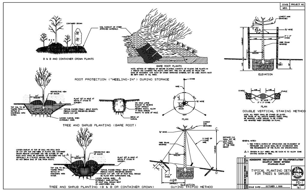
18 References BMPs from Volume 1 Chapter 4 Permanent Seeding (PS) 4-53 Shrub, Vine and Groundcover Planting (SVG) 4-80 Tree Planting on Disturbed Areas (TP) Filter Strip (FS) Channel Stabilization (CS) MDOT Drawing PD-1 Typical Planting Details for Trees and Shrubs Additional Resources Allen, H.H., and Fischenich, J.C. (1999) Coir geotextile roll and wetland plants for streambank erosion control, EMRRP Technical Notes Collection (ERDC TN-EMRRP- SR-04), U.S. Army Engineer Research and Development Center, Vicksburg, MS. Bentrup, G., and Hoag, C. (1998) The Practical Streambank Bioengineering Guide Interagency Riparian/Wetland Plant Development Project. USDA. Freeman, G., and Fischenich, C. (2001). Units and Conversions for Stream Restoration Projects, EMRRP Technical Notes Collection (ERDC TN-EMRRP-SR-28), U.S. Army Engineer Research and Development Center, Vicksburg, MS. Fischenich, C. (1999). Irrigation systems for establishing riparian vegetation, EMRRP Technical Notes Collection (ERDC TN-EMRRP-SR-12), U.S. Army Engineer Research and Development Center, Vicksburg, MS. Fischenich, J.C., and Allen H. (2000). U.S. Army Engineer Research and Development Center, Environmental Laboratory, SR-W Fischenich, C., and Morrow, J., Jr. (1999). Streambank Habitat Enhancement with Large Woody Debris, EMRRP Technical Notes Collection (ERDC TN-EMRRP-SR-13), U.S. Army Engineer Research and Development Center, Vicksburg, MS. Fisher, R.A., and Fischenich, J.C. (2000). Design recommendations for riparian corridors and vegetated buffer strips, EMRRP Technical Notes Collection (ERDC TN- EMRRP-SR-24), U.S. Army Engineer Research and Development Center, Vicksburg, MS
19 Sotir, R.B., and Fischenich, J.C. (2001), Live and Inert Fascine Streambank Erosion Control, EMRRP Technical Notes Collection (ERDC TN-EMRRP-SR-31), U.S. Army Engineer Research and Development Center, Vicksburg, MS
20 4-381
Guidelines for Streambank Protection
 PDHonline Course C187 (3 PDH) Guidelines for Streambank Protection Instructor: John Poullain, PE 2012 PDH Online PDH Center 5272 Meadow Estates Drive Fairfax, VA 22030-6658 Phone & Fax: 703-988-0088 www.pdhonline.org
Buffer Zone (BZ) Stream Protection. The width and plant composition of a buffer zone will determine its effectiveness.
 Stream Protection. The width and plant composition of a buffer zone will determine its effectiveness.") Buffer Zone (BZ) Figure BZ-1 Buffer Zone in Agricultural Area Practice Description A buffer zone is a strip of plants adjacent to land-disturbing sites or bordering streams, lakes, and wetlands that provides
Buffer Zone (BZ) Figure BZ-1 Buffer Zone in Agricultural Area Practice Description A buffer zone is a strip of plants adjacent to land-disturbing sites or bordering streams, lakes, and wetlands that provides
Bio-Engineering Techniques to Revegetate Streambanks
 Bio-Engineering Techniques to Revegetate Streambanks DORMANT CUTTINGS Dormant cuttings are harvested from living woody plants. The cuttings are prepared from branches of woody plants when the plant is
VEGETATED SLOPE STABILIZATION DESCRIPTION APPLICABILITY. Advantages
 4.2-d VEGETATED SLOPE STABILIZATION Alternative Names: Willow Wattles, Live Bundles, Fascines, Live Staking, Joint Planting, Branch Packing, Brush Layering, and Brush Matting DESCRIPTION Vegetated slope
Biotechnical streambank stabilization
 Traditional streambank stabilization Biotechnical streambank stabilization Channelization alters: shape pattern slope bed morphology cover Ecological effects: loss of riparian habitat loss of fish habitat
STREAM ALTERATION PRACTICES
 STREAM ALTERATION PRACTICES Stream Diversion Channel SDC DEFINITION A temporary channel constructed to convey stream flow around in-stream construction. PURPOSE Stream diversion channels are used to allow
HYDRAULIC DESIGN involves several basic
 Chapter 6 Tools for Hydr draulic and Road Design HYDRAULIC DESIGN involves several basic concepts that must be considered to build successful projects with a minimum risk of failure (Photo 6.1). Use of
Technical Supplement 14D. Geosynthetics in Stream Restoration. (210 VI NEH, August 2007)
") Technical Supplement 14D (210 VI NEH, August 2007) Issued August 2007 Cover photo: Inert or manmade materials can be used in restoration designs where immediate stability is required and can be used in
Technical Supplement 14D (210 VI NEH, August 2007) Issued August 2007 Cover photo: Inert or manmade materials can be used in restoration designs where immediate stability is required and can be used in
Department of Agriculture. Conservation Service. United States. Natural Resources REVISED 8/26/16
 GENERAL NOTES: SYMBOL LEGEND 1. All work shall comply with the constriction specifications, drawings, project-specific quality assurance plan and other contract requirements. 2. All notes on the drawings
Soil bioengineering and ecological
 Soil bioengineering and ecological systems Techniques Click to proceed... Copyright 2001 Maccaferri Inc. All rights reserved. All reproduction, including photocopy, film and microfilm, is forbidden. Release
HOW TO CONTROL STREAMBANK EROSION
 6 HOW TO CONTROL STREAMBANK EROSION Prepared by the Iowa Department of Natural Resources In cooperation with the Natural Resources Conservation Service, U.S. DEPARTMENT OF AGRICULTURE 2006 The 1984 printing
DITCH BANK STABILIZATION TECHNIQUES
 onstructed Ditch Drainage anagement Guide - No. 0 in series Order No. 5.0- December 00 DITH BANK STABILIZATION TEHNIQUES It is important to maintain ditches using practices that ensure ditch banks remain
USING PLANTS TO STABILIZE STREAM BANKS
 USING PLANTS TO STABILIZE STREAM BANKS This handout is intended to provide you with a general orientation to the three most common and practicable soil-bioengineering techniques. In a number of situations,
Section Specification for Geotextile Used in Permanent Erosion Control Application
 Project Name: Project Number: 1 GENERAL Section 02370 Specification for Geotextile Used in Permanent Erosion Control Application 1.1 SECTION INCLUDES A. Geotextile to prevent soil loss resulting in excessive
Alternative Names: Erosion Control Matting, Erosion Control Netting, Rolled Erosion Control Products (RECP)
") 4.5-s EROSION CONTROL BLANKET SYSTEM Alternative Names: Erosion Control Matting, Erosion Control Netting, Rolled Erosion Control Products (RECP) DESCRIPTION Erosion control blanket systems are woven or
4.5-s EROSION CONTROL BLANKET SYSTEM Alternative Names: Erosion Control Matting, Erosion Control Netting, Rolled Erosion Control Products (RECP) DESCRIPTION Erosion control blanket systems are woven or
Stream Bank Erosion: Soil Bioengineering Solutions
 Stream Bank Erosion: Soil Bioengineering Solutions The principal causes of streambank erosion can be classed as geologic, climatic, vegetative, and hydraulic. These causes may act independently, but normally
Coir Block System (fabric attached coir block) add New Dimension to Streambank Stabilization Projects
 add New Dimension to Streambank Stabilization Projects") Coir Block System (fabric attached coir block) add New Dimension to Streambank Stabilization Projects Using geotextiles to confine soil in lifts between layers of live plants has become an increasingly
Coir Block System (fabric attached coir block) add New Dimension to Streambank Stabilization Projects Using geotextiles to confine soil in lifts between layers of live plants has become an increasingly
PERMANENT SEEDING. Overview of Sedimentation and Erosion Control Practices. Practice no. 6.11
 Overview of Sedimentation and Erosion Control Practices Practice no. 6.11 PERMANENT SEEDING Permanent vegetation controls erosion by physically protecting a bare soil surface from raindrop impact, flowing
CHAPTER 5. Soil Bioengineering Techniques
 CHAPTER 5 Soil Bioengineering Techniques Soil bioengineering is an applied science that combines the use of engineering design principles with biological and ecological concepts to construct and assure
Live Stake and Joint Planting for Streambank Erosion Control
 Live Stake and Joint Planting for Streambank Erosion Control by Robbin B. Sotir and J. Craig Fischenich November 2007 Complexity Environmental Value Cost Low Moderate High Low Moderate High Low Moderate
SECTION 6. Routine Maintenance Activity Details
 SECTION 6 Routine Maintenance Activity Details 80. DEBRIS REMOVAL When Deadfall, and other objects, such as shopping carts, tires, appliances, and mattresses have accumulated in the drain. Why To prevent
EROSION & SEDIMENT CONTROL
 EROSION & SEDIMENT CONTROL 1 EROSION & SEDIMENT CONTROL Effective Soil & Water Protection Whether you want to prevent soil erosion caused by rain, water and wind, or protect waterways from inevitable build
SECTION SOIL BIOENGINEERING OR SHORELINE STABILIZATION
 SECTION 32 93 43 SOIL BIOENGINEERING OR SHORELINE STABILIZATION PART 1 GENERAL 1.01 SECTION INCLUDES A. CONTRACTOR shall furnish all labor, materials, supplies, equipment, tools and transportation; perform
Wisconsin Contractors Institute Continuing Education
 Wisconsin Contractors Institute Continuing Education Erosion & Sediment Control Course # 12775 2 hours Wisconsin Contractors Institute N27 W23953 Paul Road, Suite 203 Pewaukee, WI 53072 Website: www.wicontractorsinstitute.com
Bioengineered designs
 Bioengineered designs In bioengineered designs, plants are essential for the long-term integrity of the water s edge. Certain hard elements may be included, such as driven wooden piles, but their functions
ACTIVITY: Geotextiles ES 12
 Targeted Constituents Significant Benefit Partial Benefit Low or Unknown Benefit Sediment Heavy Metals Floatable Materials Oxygen Demanding Substances Nutrients Toxic Materials Oil & Grease Bacteria &
THE OBJECTIVES OF ROUTINE ROAD CUTS AND FILLS
 Chapter 11 Slope Stabiliza bilization and Stability of Cuts and Fills THE OBJECTIVES OF ROUTINE ROAD CUTS AND FILLS are 1) to create space for the road template and driving surface; 2) to balance material
The Toe Wood Structure
 The Toe Wood Structure by Dave Rosgen Objectives: Enhance fish habitat/food chains Stabilize streambanks Maintain a low width/depth ratio Provide a more natural appearance & improve visual values Be compatible
E R O S I O N C O N T R O L
 E R O S I O N C O N T R O L GEOTEXTILES T O U G H O V E R T I M E EROSION CONTROL 1.0 Features of PERMANENT PG 2 EROSION CONTROL 2.0 How Typar geotextiles PG 2 work 4.0 Installation guide PG 6 5.0 Overlap
Low Gradient Velocity Control Short Term Steep Gradient [1] Channel Lining Medium-Long Term Outlet Control Soil Treatment Permanent
![Low Gradient Velocity Control Short Term Steep Gradient [1] Channel Lining Medium-Long Term Outlet Control Soil Treatment Permanent](/thumbs/77/74849271.jpg "Low Gradient Velocity Control Short Term Steep Gradient [1] Channel Lining Medium-Long Term Outlet Control Soil Treatment Permanent") Grass Linings DRAINAGE CONTROL TECHNIQUE Low Gradient Velocity Control Short Term Steep Gradient [1] Channel Lining Medium-Long Term Outlet Control Soil Treatment Permanent [1] May be used on short, steep
Grass Linings DRAINAGE CONTROL TECHNIQUE Low Gradient Velocity Control Short Term Steep Gradient [1] Channel Lining Medium-Long Term Outlet Control Soil Treatment Permanent [1] May be used on short, steep
5. LOW IMPACT DEVELOPMENT DESIGN STANDARDS
 5. LOW IMPACT DEVELOPMENT DESIGN STANDARDS Low Impact Development (LID) requires a shift in stormwater management away from conveying runoff to a small number of downstream points through hydraulically
Vegetating Disturbed Road & Stream Banks. By Mike Fournier NRCS Resource Conservationist
 Vegetating Disturbed Road & Stream Banks By Mike Fournier NRCS Resource Conservationist Clearly Identify The Problem Project Objectives Clearly Define Objectives Before Work Starts Determine Whether Project
Urban Conservation Practice Physical Effects ESTABLISHMENT, GROWTH, AND HARVEST NUTRIENT MANAGEMENT
 NOT WELL 800 - Urban Stormwater Wetlands A constructed system of shallow pools that create growing conditions for wetland plants to lessen the impacts of stormwater quality and quantity in urban areas.
Banking on Natural Fibers Products made from coir and jute play a key role in stabilizing a restored stream for a commercial stream mitigation bank.
 Banking on Natural Fibers Products made from coir and jute play a key role in stabilizing a restored stream for a commercial stream mitigation bank. By Greg Northcutt When White Creek Mitigation, LLC,
V. EROSION CONTROL. -Drainage swales separation -Under rip-rap protected -Under rip-rap unprotected
 V. EROSION CONTROL This section describes three different types of erosion control applications where geotextiles can be used in conjunction with some form of stone or other energy dissipating material
AASHTO M Subsurface Drainage
 Subsurface Drainage Description: This specification is applicable to placing a geotextile against the soil to allow long-term passage of water into a subsurface drain system retaining the in -situ soil.
SECTION 02230BP AGGREGATE BASE
 SECTION 02230BP AGGREGATE BASE This page is intentionally left blank. Fluor-B&W Portsmouth, LLC (FBP) SITE PREPARATION INFRASTRUCTURE PHASE 1 SPECIFICATION COVER SHEET Client: U.S. Department of Energy
Town of Essex Small Site Erosion Control Guide
 Town of Essex Small Site Erosion Control Guide Why do we need to protect against erosion? Water Quality: Erosion and the transport of sediment and pollutants impacts the water quality of nearby streams
SKAPS GEOTEXTILE SUBSURFACE DRAINAGE
 SKAPS INDUSTRIES 335 Athena Drive, Athens, GA 30601 Ph: (706)-354-3700 Fax: (706)-354-3737 Email: contact@skaps.com DROP-IN SPECIFICATIONS SKAPS GEOTEXTILE SUBSURFACE DRAINAGE The following drop-in specification
4.6. Low Impact and Retentive Grading
 4.6. Low Impact and Retentive Grading Low Impact Grading techniques focus on utilizing existing topography during Site layout to minimize cost. Proposing structures, roads, and other impervious surfaces
5.0 Storm Water Landscape Guidance Introduction
 5.0 Storm Water Landscape Guidance Introduction Landscaping is a critical element to improve both the function and appearance of storm water management practices. Integrated storm water landscapes can
2.1.4 Roof Downspout Rain Gardens
 2008 SWMM, 2010 Revision City of Tacoma 2.1.4 Roof Downspout Rain Gardens Purpose and Definition Bioretention areas are shallow stormwater retention facilities designed to mimic forested systems by controlling
RIVER TRAINING STRUCTURES
 RIVER TRAINING STRUCTURES SPUR DIKES Spur dikes, deflectors or groins are transverse structures that extend into the stream from the bank and reduce erosion by deflecting flows away from the bank. Transverse
FOR PROJECTS INITIATED AFTER FEBRUARY 1, 2010 REVISION 1 ITEM 709 TRIANGULAR FILTER FABRIC FENCE
 AFTER FEBRUARY 1, 2010 ITEM 709 TRIANGULAR FILTER FABRIC FENCE 709.1 Description. This work shall consist of furnishing, installing, and removing temporary erosion protection and sediment control triangular
Structural Storm Water Best Management Practices (BMPs)
") Structural Storm Water Best Management Practices (BMPs) Storm Water Permitting: The SWPPP Revealed By Deron Austin, PE January 11, 2006 3:30-5:00 PM Orlando, Florida Presentation Outline Preface About
Structural Storm Water Best Management Practices (BMPs) Storm Water Permitting: The SWPPP Revealed By Deron Austin, PE January 11, 2006 3:30-5:00 PM Orlando, Florida Presentation Outline Preface About
Harvesting Stem Cuttings for Riparian Planting
 17507 Fort Road Edmonton AB T5Y 6H3 Phone: 780-643-6732 Email: info@awes-ab.ca Harvesting Stem Cuttings for Riparian Planting The following factsheet describes what stem cuttings are and how to harvest
INSTALLATION GUIDELINES FOR GEOTEXTILES USED IN FILTRATION AND DRAINAGE APPLICATIONS
 INSTALLATION GUIDELINES FOR GEOTEXTILES USED IN FILTRATION AND DRAINAGE APPLICATIONS Prepared by TenCate Geosynthetics North America 365 South Holland Drive Pendergrass, GA 30567 Tel: (706) 693-2226 Fax:
Post Construction BMPs
 Post Construction BMPs Why are Post Construction BMPs important? With increased development brings the increase of impervious cover Parking lots, rooftops, driveways Storm water runoff volume increases
Wisconsin NRCS Direct Volume Method Bank Recession Rate Categorizations
 2 Executive Summary The City of Ramsey contracted the Anoka Conservation District to complete an inventory of riverbank condition along the entire 5.8 miles of City that border the Mississippi River. The
III.DRAINAGE. This section describes the use of geotextiles in underdrains for two different field conditions:
 III.DRAINAGE This section describes the use of geotextiles in underdrains for two different field conditions: Protected (or light duty installations) and, Unprotected (for heavy duty installations). Both
Lake Shoreline Stabilization Techniques
 Environment and Sustainable Resource Development Lake Shoreline Stabilization Techniques Compliance Assurance / Operations Central Region Suite #1, 250 Diamond Avenue Box 4240 Spruce Grove, Alberta T7X
H841:02 Deep and severe erosion of roadside ditch to form gullies. H837:02 Deep erosion of roadside ditch
 Cellular Confinement System (BMP 15) Cellular Confinement System (BMP 15) H841:02 Deep and severe erosion of roadside ditch to form gullies H841:02 Backfilling of gullies and installing geocells filled
Table 4.7.1: Swales Potential Application and Storm Water Regulation
 4.7. Swales A swale is a vegetated open channel, planted with a combination of grasses and other herbaceous plants, shrubs, or trees. A traditional swale reduces peak flow at the discharge point by increasing
Subsurface Infiltration Bed
 Subsurface Infiltration Bed The Subsurface Infiltration Bed BMP consists of a storage bed underlying either a vegetated or hardscaped surface for the purpose of temporary storage and infiltration of stormwater
Riparian Restoration Plan for the Quiet Waters Homeowners Association Reach of the Yachats River. Site Overview
 Walama Restoration Project Community Supported Rehabilitation And Native Re-vegetation of our Watersheds PO Box 894 Eugene, OR 97440 541.484.3939 info@walamarestoration.org www.walamarestoration.org Riparian
INDEX STREAM PROTECTION TEMPORARY STREAM CROSSING PERMANENT STREAM CROSSING VEGETATIVE STREAMBANK STABILIZATION 6.73.
 6 INDEX STREAM PROTECTION TEMPORARY STREAM CROSSING PERMANENT STREAM CROSSING VEGETATIVE STREAMBANK STABILIZATION STRUCTURAL STREAMBANK STABILIZATION BUFFER ZONES 6.70.1 6.71.1 6.72.1 6.73.1 6.74.1 Rev.
Stop Losing Ground to Erosion. Kimberly Laframboise Ecologist Michalski Nielsen Associates limited
 Stop Losing Ground to Erosion Kimberly Laframboise Ecologist Michalski Nielsen Associates limited Forms of Erosion Surface erosion Sheet erosion Wind erosion Wave action Mass-movement erosion Slips, earth
General Information. Site Conditions. 9b 9b. 9a 1b. Best Management Practices Illustration
 Model Construction SWPPP Planning & Development Services 1800 Continental Place Mount Vernon WA 98273 voice 360-416-1320 inspections 360-416-1330 www.skagitcounty.net/stormwaterpermitting Permit #: General
Coir Fibers Help Strengthen Environmentally-Friendly Golf Course Stream Restoration Project
 Coir Fibers Help Strengthen Environmentally-Friendly Golf Course Stream Restoration Project RoLanka International, Inc. 2004 Stabilizing nearly two miles of streambanks and slopes wasn t the only challenge
Guidelines for Installing Rolled Erosion Control Products in Slope, Channel and Shoreline Applications Laurie Honnigford
 Guidelines for Installing Rolled Erosion Control Products in Slope, Channel and Shoreline Applications Laurie Honnigford Soil erosion is evident in so many situations and the environmental impact can be
Alternate Green Stream Bank Stabilization Methods
 U.S. Army Corps of Engineers Philadelphia/Baltimore Districts Alternate Green Stream Bank Stabilization Methods Wissahickon Creek, Tannery Run and Rose Valley Creek Bo-Rit Asbestos Site Ambler, Pennsylvania
Section 3: Erosion and Sediment Control Best Management Practices
 Section 3: Erosion and Sediment Control Best Management Practices 3.1 Introduction 19 3.2 Permanent Erosion Control 19 3.2.1 Vegetation 20 3.2.2 Native and Adapted Vegetation Species 20 3.2.3 Soils and
Basic Geosynthetics: A Guide to Best Practices in Forest Engineering
 Basic Geosynthetics: A Guide to Best Practices in Forest Engineering Jonathan Fannin Ph.D., P. Eng., Forest Resources Management and Civil Engineering, University of British Columbia, Canada. ABSTRACT
FirstLight Power Shoreline Management Manual Sustainable Shoreline Designs: From Long Island to Lake Erie Webinar Series
 FirstLight Power Shoreline Management Manual Sustainable Shoreline Designs: From Long Island to Lake Erie Webinar Series Presented by Jason Williams, PLA, NCI February 19, 2017 Introduction Lakes (impoundments)
Information for File # JTF
 Information for File # 2013-04665-JTF Applicant Corps Contact Enbridge Energy, Limited Partnership Josh Fitzpatrick Address 1554 Highway 2, Suite 2, Two Harbors, MN 55616 E-Mail joshua.t.fitzpatrick@usace.army.mil
SECTION 808 PLANTING TREES, SHRUBS AND OTHER PLANTS
 SECTION 808 PLANTING TREES, SHRUBS AND OTHER PLANTS 808.1 Description. This work shall consist of furnishing and planting material in the locations designated on the plans or established by the engineer.
ACTIVITY: Trees, Shrubs and Vines ES 10
 Targeted Constituents Significant Benefit Partial Benefit Low or Unknown Benefit Sediment Heavy Metals Floatable Materials Oxygen Demanding Substances Nutrients Toxic Materials Oil & Grease Bacteria &
Guiding Landowners in Stream Restoration. The Science, Practice & Art of Restoring Native Ecosystems 2015
 Guiding Landowners in Stream Restoration The Science, Practice & Art of Restoring Native Ecosystems 2015 January 24, 2015 Guiding Landowners in Stream Restoration January 24, 2015 Agenda 1Watershed Planning
REFERENCE DRAWINGS FOR 332 W. MAIN STREET ROCK HILL, SOUTH CAROLINA
 REFERENCE DRAWINGS FOR REET ROCK HILL, SOUTH CAROLINA COVER SHEET 1 OF 6 GENERAL NOTES 2 OF 6 REMOVE WIRE AND NYLON TWINE FROM BALL AND CANOPY. SOAK ROOT BALL AND PLANT PIT IMMEDIATELY AFTER INSTALLATION.
Illinois Urban Manual
 Illinois Urban Manual Jim Nelson: Association of Illinois Soil and Water Conservation Districts (AISWCD) Funding for this project provided, in part, by the Grand Victoria Foundation of Elgin IL, the Governor
Stream Restoration: Working with Nature?
 Stream Restoration: Working with Nature? Greg Jennings, PhD, PE jenningsenv@gmail.com Ecosystem Restoration activities that initiate or accelerate the recovery of ecosystem health, integrity, and sustainability
Stream Restoration: Working with Nature? Greg Jennings, PhD, PE
 Stream Restoration: Working with Nature? Greg Jennings, PhD, PE jenningsenv@gmail.com Ecosystem Restoration activities that initiate or accelerate the recovery of ecosystem health, integrity, and sustainability
511 - RIP RAP - OPSS 511 ROCK PROTECTION - OPSS 511 GRAVEL SHEETING - OPSS 511 GEOTEXTILE - OPSS 511
 511 - - OPSS 511 ROCK PROTECTION - OPSS 511 GRAVEL SHEETING - OPSS 511 GEOTEXTILE - OPSS 511 511.1 GENERAL 511.1.1 Rip Rap 511.1.2 Rock Protection Excavation for placing Rip Rap, Rock Protection and Gravel
DRIVABLE GRASS GUIDELINE FOR PLANTED INFILL INSTALLATION
 DRIVABLE GRASS GUIDELINE FOR PLANTED INFILL INSTALLATION Please read through this instruction completely before beginning your installation. Be sure the proper equipment, and safety precautions are in
Section 815. LANDSCAPING
 815.01 Section 815. LANDSCAPING 815.01. Description. This work consists of providing and planting trees, shrubs, and other plants, including replacements, classified as nursery stock. The Engineer may
6.0 Soil Bioengineering for Slope Stability
 6.0 Soil Bioengineering for Slope Stability 6.1 Introduction Soil bioengineering can be an effective means of treating eroding surfaces and unstable surficial soil layers in the forest environment. Soil
Module 5 Erosion & Sediment Control. Introduction To Geosynthetics In Transportation. Prepared by. For the Local Technical Assistance Program
 Module 5 Erosion & Sediment Control Introduction To Geosynthetics In Transportation Prepared by July 2007 For the Local Technical Assistance Program The Geosynthetic Materials Association (GMA) represents
A. Install all temporary erosion control measures (in accordance with MNDOT General Conditions 2573) prior to site disturbance.
 prior to site disturbance.") The language provided in these specifications is meant to serve as a reminder and provide a generic example of the type of language that should be provided in final construction documents. This language
The language provided in these specifications is meant to serve as a reminder and provide a generic example of the type of language that should be provided in final construction documents. This language
I N D U S T R I A L Y A R D S
 I N D U S T R I A L Y A R D S GEOTEXTILES INDUSTRIAL YARDS 1.0 Features of INDUSTRIAL PG 2 YARDS 2.0 How Typar geotextiles PG 2 work 4.0 Installation guide PG 7 5.0 Overlap and joining PG 8 6.0 Setting
Rolled Erosion Control Products (RECPs) General Usage and Installation Guidelines for Slope
 General Usage and Installation Guidelines for Slope") March 2014 Version 1.0 Rolled Erosion Control Products (RECPs) General Usage and Installation Guidelines for Slope Erosion Control Technology Council IMPORTANT NOTICE on Safety Procedures: Manufacturer
March 2014 Version 1.0 Rolled Erosion Control Products (RECPs) General Usage and Installation Guidelines for Slope Erosion Control Technology Council IMPORTANT NOTICE on Safety Procedures: Manufacturer
STREAM BANK STABILIZATION THORPS MORTIMER RECREATION AREA Grandfather Ranger District SITE LOCATION & DRAINAGE AREA
 STREAM BANK STABILIZATION THORPS CREEK @ MORTIMER RECREATION AREA SITE LOCATION & DRAINAGE AREA SITE LOCATION Drainage Area = 1.14 sq. miles STREAM BANK STABILIZATION THORPS CREEK @ MORTIMER RECREATION
The following general requirements will be met for all planter box installations:
 Greenville County Technical Specification for: WQ-25 PLANTER BOX 1.0 Planter Box 1.1 Description Planter boxes are designed to capture and temporarily store stormwater runoff. Planter Boxes are intended
Shoreline Stabilization Using Wetland Plants and Bioengineering
 Shoreline Stabilization Using Wetland Plants and Bioengineering by Cathy J. Wendt & Hollis H. Allen PURPOSE This is a case study in which wetland plants and bioengineering treatments were used to protect
2008 SWMM, 2010 Revision City of Tacoma
 2008 SWMM, 2010 Revision City of Tacoma 2.2.3.1 BMP L630 Rain Gardens Purpose and Definition Bioretention areas are shallow stormwater retention facilities designed to mimic forested systems by controlling
Montana Stream Permitting
 Montana Stream Permitting A Guide for Conservation District Supervisors and Others Conservation Districts Bureau Montana Department of Natural Resources and Conservation June 2001 CONTRIBUTORS Committee
SECTION 900 TURF ESTABLISHMENT
 SECTION 900 901.0 DESCRIPTION This section covers the furnishing of all labor, materials, tools, equipment and performances of all work and services necessary or incidental to turf restoration as indicated
Stormwater Standards. Clackamas County Service District No. 1. Planting Guide for Buffers
 Stormwater Standards Clackamas County Service District No. 1 APPENDIX B Planting Guide for Buffers Table of Contents Appendix B - Planting Guide for Buffers... Page B.1 General... 1 B.1.1 Introduction...
GEOMEMBRANE FIELD INSTALLATION
 GEOMEMBRANE FIELD INSTALLATION CONTENTS Introduction Quality Control and Quality Assurance Types of lining systems Basic Lining Design Executive Lining Design Basic Lining Design Specification Executive
SECTION PLANTING PART 1 - GENERAL 1.1 RELATED DOCUMENTS
 SECTION 329000 PLANTING PART 1 - GENERAL 1.1 RELATED DOCUMENTS A. Drawings and general provisions of the Contract, including General and Special Conditions and Division 01 Specification Sections, apply
Design Considerations for Open Channel and Detention Pond Design. Howard Redfearn, City of Mansfield
 Design Considerations for Open Channel and Detention Pond Design Howard Redfearn, City of Mansfield Previous Experience/Criteria/Maintenance Issues New Criteria Discussion Overview Where is Mansfield?
ALTERNATIVE SHORELINE MANAGEMENT IN COASTAL MISSISSIPPI
 ALTERNATIVE SHORELINE MANAGEMENT IN COASTAL MISSISSIPPI Project supported via financial assistance provided by the Coastal Zone Management Act of 1972, as amended, administered by the Office of the Ocean
Restoration of Riparian Buffer at the Former Smelt Hill Dam Site, Falmouth, Maine
 Restoration of Riparian Buffer at the Former Smelt Hill Dam Site, Falmouth, Maine Final Report June 30, 2006 Page 1 of 16 I. Project Title Restoration of Riparian Buffer at the Former Smelt Hill Dam Site,
RAIN GARDEN ILLINOIS URBAN MANUAL PRACTICE STANDARD. (feet) CODE 897 DEFINITION
 CODE 897 DEFINITION") ILLINOIS URBAN MANUAL PRACTICE STANDARD RAIN GARDEN (feet) CODE 897 Source: Kendall County Soil and Water Conservation District DEFINITION Rain gardens are small, shallow, flat bottomed depressions constructed
ILLINOIS URBAN MANUAL PRACTICE STANDARD RAIN GARDEN (feet) CODE 897 Source: Kendall County Soil and Water Conservation District DEFINITION Rain gardens are small, shallow, flat bottomed depressions constructed
Veranda Park Planting Plan Draft 10/08/10
 Planting Plan Native Plant Selection Trees and Shrubs Plants were selected based on what species were indentified onsite, information from the Medford Riparian Ordinance, and typical native riparian species
5 TH ANNUAL CAPE COASTAL CONFERENCE
 5 TH ANNUAL CAPE COASTAL CONFERENCE Key Considerations for Living Shoreline Projects Seth Wilkinson, Restoration Ecologist, President Wilkinson Ecological Design, Inc. BIOENGINEERING STRATEGIES Reducing
D RAFT MEMORANDUM CURRENT PLANTING TECHNIQUES. Technique 1: Bioengineered Brush Layering. To: Date: January 20, 2016
 720 Olive Way, Suite 1900 Seattle, Washington 98101 Phone 206.287.9130 Fax 206.287.9131 www.anchorqea.com D RAFT MEMORANDUM To: Rob Wenman, Pierce County Public Works and Utilities Date: From: Betsy Severtsen,
WETLAND SOD u Bare Root Wetland Plants u Deep Rooted Willows u Coir Logs u Native Trees & Shrubs u Habitat Islands u Custom Growing
 WETLAND SOD u Bare Root Wetland Plants u Deep Rooted Willows u Coir Logs u Native Trees & Shrubs u Habitat Islands u Custom Growing 2009 PROJECT HIGHLIGHTS The following 10 projects highlight the interesting
WET PONDS INSPECTION & MAINTENANCE CHECKLIST
 WET PONDS INSPECTION & MAINTENANCE CHECKLIST INTRODUCTION Once construction is completed, periodic site inspections are essential in order to monitor the effectiveness and to anticipate the maintenance
Project: Developer/Designer: Reviewer: I. Narrative: 1. Project Description: Describes the nature and purpose of the land disturbing activity.
 City of Charlottesville, Virginia Erosion and Sediment Control Plan Review Checklist 610 East Market Street, Charlottesville, VA 22902 Telephone 434-970-3182; Fax 434-970-3359 Project: Developer/Designer:
12/7/2007. Christopher B. Burke Engineering West, Ltd Aux Sable Creek Watershed Plan Update 1
 The ABC s of BMP s Aux Sable Watershed Plan St. Charles, IL Why are BMP s Important Best Management Practices (BMPs) developed as a set of practices which help to achieve goals of the Clean Water Act and