REFERENCE NO S066 JUNE 2017
|
|
|
- Doris Gallagher
- 5 years ago
- Views:
Transcription
1 0 WEST BEAVER CREEK ROAD, SUITE #0, RICHMOND HILL, ONTARIO, L4B 1E TEL (416) 4-1 FAX (0) 1-33 A REPORT TO 2413 ONTARIO LTD. A GEOTECHNICAL INVESTIGATION FOR PROPOSED RESIDENTIAL DEVELOPMENT BETTY BOULEVARD AND SHORE LANE TOWN OF WASAGA BEACH REFERENCE NO. 104-S066 JUNE 201 DISTRIBUTION 3 Copies - C.C. Tatham & Associates Ltd. 1 Copy - Soil Engineers Ltd. (Barrie) 1 Copy - Soil Engineers Ltd. (Toronto)
2 Reference No. 104-S066 ii TABLE OF CONTENTS 1.0 INTRODUCTION SITE AND PROJECT DESCRIPTION FIELD WORK SUBSURFACE CONDITIONS Topsoil Earth Fill Silty Clay Till and Silty Clay Silty Sand Till/Sandy Silt Till Compaction Characteristics of the Revealed Soils....0 GROUNDWATER CONDITIONS DISCUSSION AND RECOMMENDATIONS Foundations Engineered Fill Slab-On-Grade Underground Services Trench Backfilling Garages, Driveways and Interlocking Stone Pavement Pavement Design Soil Parameters Preloading Scheme Excavation LIMITATIONS OF REPORT...31
3 Reference No. 104-S066 iii TABLES Table 1 - Estimated Water Content for Compaction... Table 2 - Groundwater Levels...12 Table 3 - Founding Levels...16 Table 4 - Pavement Design...2 Table - Soil Parameters...2 Table 6 - Classification of Soils for Excavation...2 DRIGRAM Diagram 1 - Frost Protection Measures (Foundations)...1 ENCLOSURES Borehole Logs... Figures 1 to Grain Size Distribution Graphs... Figures to 12 Borehole Location Plan... Drawing No. 1 Subsurface Profile... Drawing No. 2
4 Reference No. 104-S INTRODUCTION In accordance with written authorization dated April 12, 201, from Mr. Ary VanderMeer of 2413 Ontario Ltd., a geotechnical investigation was carried out at a parcel of land located between Betty Boulevard and Shore Lane, in the Town of Wasaga Beach, for a proposed Residential Development. The purpose of the investigation was to reveal the subsurface conditions and to determine the engineering properties of the disclosed soils for the design and construction of the proposed project. The findings and resulting geotechnical recommendations are presented in this Report.
5 Reference No. 104-S SITE AND PROJECT DESCRIPTION The west portion of the Town of Wasaga Beach is situated in the Simcoe Lowlands, bordering the Niagara Escarpment where lacustrine sand, silt and clay deposits, and glacial tills have bedded onto undulated Black River and Trenton Group of bedrock. The investigated site, situated between Betty Boulevard and Shore Lane, in the Town of Wasaga Beach, is a vacant parcel with dense trees and bushes. The existing ground is relatively level, with undulations. The proposed project consists of the construction of a new residential subdivision, provided with municipal services and roadways meeting current municipal standards.
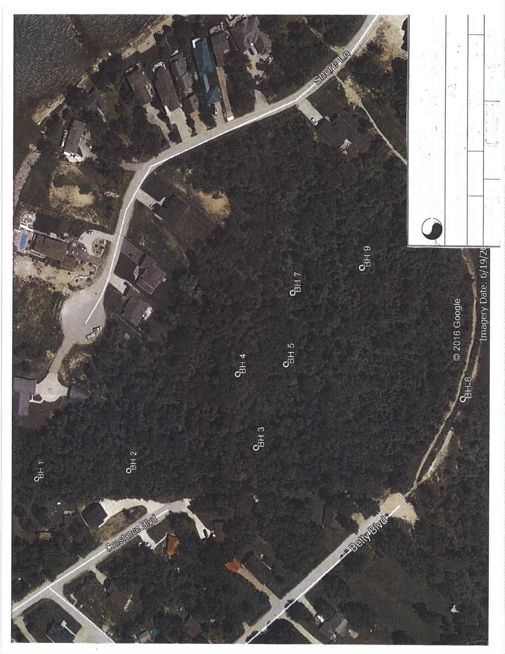
6 Reference No. 104-S FIELD WORK The field work, consisting of boreholes to depths of.0 to 6.6 m, was performed on May 4 and, 201, at the locations shown on the Borehole Location Plan, Drawing No. 1. The holes were advanced at intervals to the sampling depths by a track-mounted, continuous-flight power-auger machine equipped for soil sampling. Standard Penetration Tests, using the procedures described on the enclosed List of Abbreviations and Terms, were performed at the sampling depths. The test results are recorded as the Standard Penetration Resistance (or N values) of the subsoil. The relative density of the granular strata and the consistency of the cohesive strata are inferred from the N values. Split-spoon samples were recovered for soil classification and laboratory testing. The sampling depths and the depths of the soil strata changes were referred to the prevailing ground surface at each of the borehole locations. The field work was supervised and the findings were recorded by a Geotechnical Technician.
7 Reference No. 104-S SUBSURFACE CONDITIONS Detailed descriptions of the encountered subsurface conditions are presented on the Borehole Logs, comprising Figures 1 to, inclusive. The revealed stratigraphy is plotted on the Subsurface Profile, Drawing No. 2, and the engineering properties of the disclosed soils are discussed herein. The investigation has revealed that beneath a veneer of topsoil and a layer of earth fill in places, the site is underlain by a stratum of glacial till with embedded layers of silty clay. 4.1 Topsoil (All Boreholes, except Boreholes 6 and ) Boreholes 6 and were located beside a trail connecting to Betty Boulevard. The ground surface at these locations was bald, without vegetation or topsoil. The revealed topsoil at the other borehole locations was to 36 cm thick. It is dark brown in colour, indicating that it contains appreciable amounts of roots and humus. These materials are unstable and compressible under loads; therefore, the topsoil is considered to be void of engineering value. Due to its humus content, it may produce volatile gases and generate an offensive odour under anaerobic conditions. Therefore, the topsoil must not be buried below any structures or deeper than 1.2 m below the finished grade, so that it will not have an adverse impact on the environmental well-being of the developed areas. Since the topsoil is considered void of engineering value, it can only be used for general landscaping and landscape contouring purposes. A fertility analysis can be carried out to determine the suitability of the topsoil as a planting material.
8 Reference No. 104-S Earth Fill (Boreholes 4, 6,, and ) An earth fill was contacted at the ground surface or below the topsoil. It extended to depths of 0.6 m and 0. m below the prevailing ground surface. The fill consists of sand or silty sand, with gravel, cobbles, rock fragments and occasional topsoil inclusions. The obtained N values range from 2 to 1, with a median of blows per cm of penetration, indicating that the fill was loosely placed. Its relative density is nonuniform and is unsuitable to support any structure sensitive to settlement. The natural water content values range from % to 22%, with a median of 16%, indicating that the fill is in a moist to wet, generally wet condition, which corresponds with our sample examinations. For structural use, the existing earth fill must be subexcavated, inspected, sorted free of topsoil inclusions and any deleterious material, if detected, and properly compacted. One must be aware that the samples retrieved from boreholes cm in diameter may not be truly representative of the geotechnical and environmental quality of the fill, and do not indicate whether the topsoil beneath the earth fill was completely stripped. This should be further assessed by laboratory testing and/or test pits.
9 Reference No. 104-S Silty Clay Till (All Boreholes) and Silty Clay (Boreholes 2, 3, and 6) The silty clay till was generally encountered at the upper zone of the stratigraphy. It consists of a random mixture of soils; the particle sizes range from clay to gravel, with the clay fraction exerting the dominant influence on its soil properties. Occasional sand and silt seams and layers were also detected in the clay till mantle. The till is amorphous and heterogeneous in structure, indicating that it is a glacial deposit and has generally been reworked by the past glaciation. At Boreholes 2, 3, and 6, a silty clay deposit was contacted below the silty clay till. It is laminated with sand and silt seams and layers, showing that it is a glacio lacustrine deposit. The obtained N values range from to 2, with a median of 11 blows per cm of penetration, indicating that the consistency of the clay till is firm to very stiff, being generally stiff, confirming that the till has generally been reworked by the past glaciation. The consistency of the silty clay is soft to firm, being generally firm as shown by the N values ranging from 3 to, with a median of blows per cm. The Atterberg Limits of 1 representative sample of the clay till, 1 representative sample of the silty clay, and the natural water content values of all the samples were determined; the results are plotted on the Borehole Logs and summarized below: Clay Till Liquid Limit 43% 46% Plastic Limit 22% 23% Silty Clay Natural Water Content % to 2% 22% to 33% (median 11%) (median 24%)
10 Reference No. 104-S066 The results show that the clay and clay till are cohesive materials with medium plasticity. The natural water content generally lies below the plastic and liquid limits, confirming the generally firm or stiff consistency of the soils as determined by the N values. Grain size analyses were performed on 1 representative sample each of the clay till and the silty clay. The results are plotted on Figures and 11, respectively. Based on the above findings, the soil engineering properties pertaining to the project are given below: High frost susceptibility and high soil-adfreezing potential. Low water erodibility. Low permeability, with an estimated coefficient of permeability of - cm/sec, an estimated percolation rate of over 0 min/cm, and runoff coefficients of: Slope 0% - 2% 0.1 2% - 6% % Cohesive soils, their shear strength is primarily derived from consistency which is inversely related to its moisture content. They contains sand; therefore, their shear strength is augmented by internal friction. The soft clay is susceptible to consolidation under a surcharge load exceeding 0 kpa. In steep cuts, the firm clay till and clay will slough readily, and a cut face in the sound clay may collapse as the wet silt slowly sloughs. Bottom heaving will likely occur in trenches cut steeply into the soft clay below 4 m.
11 Reference No. 104-S066 Poor pavement-supportive materials, with an estimated CBR value of 3%. High to moderately high corrosivity to buried metal, with an estimated electrical resistivity of 2000 to 200 ohm cm. 4.4 Silty Sand Till/Sandy Silt Till (All Boreholes, except Borehole 6) The sand till or silt till was encountered at various depths and extends to the maximum investigated depth at the boreholes where it was encountered. The tills consist of a random mixture of soil particle sizes ranging from clay to gravel, with the silt and sand being the dominant fraction. They are heterogeneous in structure, showing a glacial deposit. Frequent hard resistance to augering was encountered, showing that appreciable amounts of cobbles and boulders are embedded in the till deposits The natural water content value of the samples was determined, and the results are plotted on the Borehole Logs; the values range from 6% to 20%, with a median of %, showing the till is in a moist to wet, generally moist condition. The obtained N values range from blows per cm to 0 blows per 1 cm, with a median of 3 blows per cm of penetration, showing that its relative density is loose to very dense, being generally dense. Grain size analyses were performed on 2 sand till samples and the results are plotted on Figure 12. The deduced engineering properties pertaining to the project are given below: High frost susceptibility and moderate water erodibility.
12 Reference No. 104-S066 Moderately impervious, depending on the clay content, with an estimated coefficient of permeability of - to -6 cm/sec, an estimated percolation rate of about 0 min/cm, and runoff coefficients of: Slope 0% - 2% 0.11 to 0.1 2% - 6% 0.16 to % to 0.2 A frictional soils, their shear strength is primarily derived from internal friction and is augmented by cementation. Therefore, their strength is density dependent. They will be stable in steep cuts; however, under prolonged exposure, immediate sloughing and sheet collapse will likely occur, particularly where seepage occurs. Fair pavement-supportive materials with an estimated CBR value of %. Moderately low corrosivity to buried metal, with an estimated electrical resistivity of 000 ohm cm. 4. Compaction Characteristics of the Revealed Soils The obtainable degree of compaction is primarily dependent on the soil moisture and, to a lesser extent, on the type of compactor used and the effort applied. As a general guide, the typical water content values of the revealed soils for Standard Proctor compaction are presented in Table 1.
13 Reference No. 104-S066 Table 1 - Estimated Water Content for Compaction Soil Type Determined Water Content (%) for Natural Water Standard Proctor Compaction Content (%) 0% (optimum) Range for % or + Earth Fill to 22 (median 16) Silty Clay/Clay Till to 33 (median 24) Silty Sand Till and Sandy Silt Till 6 to 20 (median ) 11 to to 26 6 to 1 Based on the above findings, the on-site material is generally suitable for a % or + Standard Proctor compaction, whereas, the wet material will require aeration in dry and warm weather prior to structural compaction. The earth fill must be sorted free of topsoil inclusions and deleterious materials prior to use as structural fill. The silty clay and tills should be compacted using a heavy-weight, kneading-type roller. The lifts for compaction should be limited to 20 cm, or to a suitable thickness as assessed by test strips performed by the equipment which will be used at the time of construction. When compacting the cemented till on the dry side of the optimum, the compactive energy will frequently bridge over the chunks in the soil and be transmitted laterally in the soil mantle. Therefore, the lifts of these soils must be limited to 20 cm or less (before compaction). It is difficult to monitor the lifts of backfill placed in deep trenches; therefore, it is preferable that the compaction of backfill at depths over 1.0 m below the pavement subgrade be carried out on the wet side of the optimum. This would allow a wider latitude of lift thickness.
14 Reference No. 104-S If the compaction of the soils is carried out with the water content within the range for % Standard Proctor dry density but on the wet side of the optimum, the surface of the compacted soil mantle will roll under the dynamic compactive load. This is unsuitable for pavement construction since each component of the pavement structure is to be placed under dynamic conditions which will induce the rolling action of the subgrade surface and cause structural failure of the new pavement. The foundation or bedding of the sewer and slab-on-grade will be placed on a subgrade which will not be subjected to impact loads. Therefore, the structurally compacted soil mantle with the water content on the wet side or dry side of the optimum will provide an adequate subgrade for the construction. The presence of boulders in the tills will prevent transmission of the compactive energy into the underlying material to be compacted. If an appreciable amount of boulders over 1 cm in size is mixed with the material, it must either be sorted or must not be used for structural backfill and/or construction of engineered fill.
15 Reference No. 104-S GROUNDWATER CONDITIONS Groundwater seepage encountered during augering was recorded on the field logs. The level of groundwater and the occurrence of cave-in were measured upon completion of the boreholes; the data are plotted on the Borehole Logs and listed in Table 2. Table 2 - Groundwater Levels BH No. Soil Colour Changes Brown to Grey Seepage Encountered During Augering Measured Groundwater/ Cave-In* Level On Completion Borehole Depth (m) Depth (m) Depth (m) Amount Depth (m) El. (m) Slight Slight Dry Slight Dry Slight Dry Slight Dry Dry Dry Groundwater was detected at depths of 4.0 m and. m at three of the boreholes; all other boreholes remained dry upon completion of field work. The groundwater represents a perched water in wet sand seams. It will fluctuate with the seasons. The soil colour changes from brown to grey at depths ranging from 1.4 to 4.0 m below the prevailing ground surface. The brown colour indicates that the soils have oxidized.
16 Reference No. 104-S In excavations, the groundwater yield is anticipated to be small and limited. It can be drained to a sump pit and removed by conventional pumping.
17 Reference No. 104-S DISCUSSION AND RECOMMENDATIONS The investigation has disclosed that beneath a veneer of topsoil and a layer of earth fill in places, the site is underlain by strata of firm to very stiff, generally stiff silty clay till and loose to very dense, generally dense sandy silt till and silty sand till, with layers of soft to firm, generally firm silty clay. Groundwater was detected at depths of 4.0 m and. m at three of the boreholes; all other boreholes remained dry upon completion of field work. The groundwater represents a perched water in wet sand seams. It will fluctuate with the seasons. The geotechnical findings which warrant special consideration are presented below: 1. The existing trees must be removed and the topsoil must be stripped for the project construction. The topsoil will generate volatile gases under anaerobic conditions and is unsuitable for engineering applications. Therefore, it should be placed in the landscaped areas only and should not be buried within the building envelope, or deeper than 1.2 m below the exterior finished grade of the project. 2. The earth fill in its present condition is not capable of supporting any structures susceptible to settlement. It must be upgraded to structural status by sorting it free of serious topsoil inclusions and deleterious material and by proper compaction. 3. The sound, natural soils are suitable for normal spread and strip footing construction. Due to the presence of topsoil and earth fill, the footing subgrade must be inspected by either a geotechnical engineer, or a geotechnical technician under the supervision of a geotechnical engineer, to ensure that its condition is compatible with the design of the foundation.
18 Reference No. 104-S The project site is underlain by strata of soft to firm silty clay or till at various depths and locations, caution must be exercised in the construction of the project where excessive earth fill or over 2 m will be placed for site grading.. The soft silty clay will consolidate under surcharge loads. Where the site grade will be raised by more than 2 m, a preloading scheme incorporating the proposed building load and the surcharge load will be required. The amount of fill required for the preloading must be assessed once the site grading plans and the details of houses have been determined. Settlement plates should be installed to monitor the degree of consolidation of the underlying soils prior to the construction of the project. The suitable time of commencing the project construction should be carefully monitored by settlement plates to ensure that the consolidation of the soft clay is completed. 6. For slab-on-grade construction, the slab should be placed on sound soil or properly compacted earth fill. Any loose soil or soft areas in the subgrade must be subexcavated and replaced with inorganic material compacted to % or + Standard Proctor dry density.. A Class B bedding, consisting of compacted 20-mm Crusher-Run Limestone, is recommended for the construction of the underground services. The sewer joints should be leak-proof, or wrapped with an appropriate waterproof membrane to prevent subgrade migration.. The revealed soils are frost susceptible, with high soil-adfreezing potential. Where these soils are used to backfill against foundation walls, special measures must be incorporated into the building construction to prevent serious damage due to soil adfreezing.. Excavation into the very dense till containing boulders will require extra effort and the use of a heavy-duty backhoe equipped with a rock-ripper. Boulders larger than 1 cm in size are not suitable for structural backfill.. Bottom heaving will likely occur in trenches cut steeply to depths of more than.0 m into the soft clay. Therefore, the spoil from the excavations should be
19 Reference No. 104-S placed at a distance from the edge of the excavation at least equal to 3 times the depth of the excavation, and the sides should be cut at 1 vertical: 2 or + horizontal. 11. It is advised that the contractor be requested to record the occurrences of soft clay during trenching. This information can be used to forewarn the house builders to exercise caution in footing construction. The recommendations appropriate for the project described in Section 2.0 are presented herein. One must be aware that the subsurface conditions may vary between boreholes. Should this become apparent during construction, a geotechnical engineer must be consulted to determine whether the following recommendations require revision. 6.1 Foundations Based on the borehole findings, the house footings for the proposed project must be placed below the topsoil, earth fill and onto the sound native soils. The recommended soil pressures and suitable founding levels are presented in Table 3. Table 3 - Founding Levels Recommended Maximum Allowable Soil Pressure (SLS)/ Factored Ultimate Soil Bearing Pressure (ULS) and Suitable Founding Level kpa (SLS) 120 kpa (ULS) 10 kpa (SLS) 20 kpa (ULS) BH No. Depth (m) Depth (m) to 4.0 * 4.0 or to 4.* 4. or to 4.* 4. or to or +
20 Reference No. 104-S066 1 Table 3 Founding Levels (Cont d) Recommended Maximum Allowable Soil Pressure (SLS)/ Factored Ultimate Soil Bearing Pressure (ULS) and Suitable Founding Level kpa (SLS) 120 kpa (ULS) 10 kpa (SLS) 20 kpa (ULS) BH No. Depth (m) Depth (m) 1.0 to 4.* 4. or or to or or or + * Due to the soft or firm clay and clay till the Designed Bearing Pressures should be reduced to 0 kpa (SLS) and 0 kpa (ULS) below the founding depth of 2 m from the prevailing ground surface The recommended soil pressures (SLS) incorporate a safety factor of 3. The total and differential settlements of the foundations are estimated to be 40 mm and 2 mm, respectively. The footing subgrade should be inspected by either a geotechnical engineer, or a geotechnical technician under the supervision of a geotechnical engineer, to ensure that the revealed conditions are compatible with the foundation design requirements. Foundations exposed to weathering or in unheated areas should be protected against frost action by a minimum of 1. m of earth cover, or must be properly insulated. Where a basement is contemplated, perimeter subdrains and dampproofing of the foundation walls will be required. All the subdrains must be encased in a fabric filter to protect them against blockage by silting, and must be connected to a positive outlet.
21 Reference No. 104-S066 1 Where soft clay is present, it will consolidate under a surcharge load exceeding 0 kpa. In case the site will be raised by more than 2 m of earth fill, the site should be pregraded with an engineered fill, and a pre-loading scheme incorporating the proposed building load and finished grade load should be carried out. While settlement will typically occur for about 4 to 6 months after placement of the surcharge fill, the suitable time for commencing the project construction should be carefully monitored by settlement plates to ensure that the consolidation of the soft clay is complete. The surcharge load for the preloading program can be determined when the site grading and the underside of footing for the buildings are available. The occurring soils are high in frost heave and soil-adfreezing potential. If these soils are to be used for the foundation backfill, the foundation walls should be shielded by a polyethylene slip-membrane for protection against soil adfreezing. The membrane will allow vertical movement of the heaving soil (due to frost) without imposing structural distress on the foundations. The recommended measures are schematically illustrated in Diagram 1. Diagram 1 - Frost Protection Measures (Foundations) 1.1.2m m Folded Heavy Polyethylene Slip-Membrane (Closed End Up) Subdrain Encased in Fabric Filter Covered with 1-mm Clear Stone
22 Reference No. 104-S066 1 The necessity to implement the above recommendations should be further assessed by a geotechnical engineer at the time of construction. The foundations must meet the requirements specified by the latest Ontario Building Code, and the buildings must be designed to resist a minimum earthquake force using Site Classification D (stiff soil). 6.2 Engineered Fill Where earth fill is required to raise the site or where extended footings are necessary, the engineering requirements for a certifiable fill for road construction, municipal services, slab-on-grade, and footings designed with a Maximum Allowable Soil Pressure (SLS) of kpa and a Factored Ultimate Soil Bearing Pressure (ULS) of 120 kpa, are presented below: 1. The topsoil must be removed. The loose earth fill must be subexcavated. The subgrade must be inspected and surface proof-rolled. 2. Inorganic soils must be used, and they must be uniformly compacted in lifts 20 cm thick to % or + of their maximum Standard Proctor dry density up to the proposed finished grade. The soil moisture must be properly controlled on the wet side of the optimum. If the house foundations are to be built soon after the fill placement, the densification process for the engineered fill must be increased to 0% of the maximum Standard Proctor compaction. 3. If imported fill is to be used, it should be inorganic soils, free of deleterious material with environmental issue (contamination). Any potential imported earth fill from off-site must be reviewed for geotechnical and environmental quality by the appropriate personnel as authorized by the developer or agency, before hauling to the site.
23 Reference No. 104-S If the engineered fill is to be left over the winter months, adequate earth cover or equivalent must be provided for protection against frost action.. The engineered fill must extend over the entire graded area; the engineered fill envelope and finished elevations must be clearly and accurately defined in the field, and must be precisely documented by qualified surveyors. Foundations partially on engineered fill must be reinforced by two 1-mm steel reinforcing bars in the footings and upper section of the foundation walls, or be designed by a structural engineer to properly distribute the stress induced by the abrupt differential settlement (about 2 mm) between the natural soil and engineered fill. 6. The engineered fill must not be placed during the period from late November to early April when freezing ambient temperatures occur either persistently or intermittently. This is to ensure that the fill is free of frozen soils, ice or snow.. Where the fill is to be placed on a bank steeper than 1 vertical:3 horizontal, the face of the bank must be flattened to 3 + so that it is suitable for safe operation of the compactor and the required compaction can be obtained.. Where the ground is wet due to subsurface water seepage, an appropriate subdrain scheme must be implemented prior to the fill placement, particularly if it is to be carried out on sloping ground.. The fill operation must be inspected on a full-time basis by a technician under the direction of a geotechnical engineer.. The footing and underground services subgrade must be inspected by the geotechnical consulting firm that supervised the engineered fill placement. This is to ensure that the foundations are placed within the engineered fill envelope, and the integrity of the fill has not been compromised by interim construction, environmental degradation and/or disturbance by the footing excavation.
24 Reference No. 104-S Any excavation carried out in certified engineered fill must be reported to the geotechnical consultant who supervised the fill placement in order to document the locations of excavation and/or to supervise reinstatement of the excavated areas to engineered fill status. If construction on the engineered fill does not commence within a period of 2 years from the date of certification, the condition of the engineered fill must be assessed for re-certification. 12. Despite stringent control in the placement of the engineered fill, variations in soil type and density may occur in the engineered fill. Therefore, the strip footings and the upper section of the foundation walls constructed on the engineered fill may require continuous reinforcement with steel bars, depending on the uniformity of the soils in the engineered fill and the thickness of the engineered fill underlying the foundations. Should the footings and/or walls require reinforcement, the required number and size of reinforcing bars must be assessed by considering the uniformity as well as the thickness of the engineered fill beneath the foundations. In sewer construction, the engineered fill is considered to have the same structural proficiency as a natural inorganic soil. 13. Due to the presence of soft clay, the engineered fill must be left in place for a period of time prior to the start of any construction. This must be confirmed by the installation of settlement plates to ensure that the consolidation of the very soft to soft clay and clay till is completed prior to the start of the construction. 6.3 Slab-On-Grade The subgrade should be inspected and assessed by proof-rolling prior to slab-ongrade construction. Where loose or soft soil is detected, it should be subexcavated and replaced with inorganic material uniformly compacted to % or + of its maximum Standard Proctor dry density.
25 Reference No. 104-S Any new material for raising the grade should consist of organic-free soil compacted to at least % of its maximum Standard Proctor dry density. The slab should be constructed on a granular base 20 cm thick, consisting of 20-mm Crusher-Run Limestone, or equivalent, compacted to its maximum Standard Proctor dry density. A Modulus of Subgrade Reaction of 20 MPa/m can be used for the design of the floor slab. If the subgrade is wet, a vapour barrier must be placed below the granular base of the floor slab to prevent upfiltration of moisture that may wet the slab surface. The ground around the buildings must be graded to direct water away from the structure to minimize the frost heave phenomenon generally associated with the disclosed soils. The requirements for the above measures can be further assessed during construction. 6.4 Underground Services The subgrade for the underground services should consist of natural soils or compacted organic-free earth fill. Where topsoil, earth fill and soft subgrade are encountered, these materials must be subexcavated and replaced with properly compacted bedding material.
26 Reference No. 104-S A Class B bedding, consisting of compacted 20-mm Crusher-Run Limestone, is recommended for the construction of the underground services. The pipe joints should be leak-proof or wrapped with an appropriate waterproof membrane to prevent subgrade migration. Where the subgrade consists of soft soils, it should be subexcavated and replaced by the bedding material. In order to prevent pipe floatation when the sewer trench is deluged with water, a soil cover with a thickness equal to the diameter of the pipe should be in place at all times after completion of the pipe installation. Openings to subdrains and catch basins should be shielded with a fabric filter to prevent blockage by silting. Since the silty clay has high to moderately high corrosivity to buried metal, the water main should be protected against corrosion. In determining the mode of protection, an electrical resistivity of 2000 ohm cm should be used. This, however, should be confirmed by testing the soil along the water main alignment at the time of sewer construction. 6. Trench Backfilling The on-site inorganic soils are suitable for trench backfill. In the zone within 1.0 m below the pavement subgrade, the backfill should be compacted to at least % of its maximum Standard Proctor dry density with the moisture content 2% to 3% drier than the optimum. In the lower zone, a % or + Standard Proctor compaction is considered to be adequate; however, the material must be compacted on the wet side of the optimum.
27 Reference No. 104-S Below the floor slab, the backfill must be compacted to % or + of its Standard Proctor dry density. In normal underground services construction practice, the problem areas of road settlement largely occur adjacent to manholes, catch basins, services crossings, foundation walls and columns, and it is recommended that a sand backfill be used. Unless compaction of the backfill is carefully performed, the interface of the native soils and the sand backfill will have to be flooded for a period of several days. The narrow trenches should be cut at 1 vertical:2 or + horizontal so that the backfill can be effectively compacted. Otherwise, soil arching will prevent the achievement of proper compaction. The lift of each backfill layer should either be limited to a thickness of 20 cm, or the thickness should be determined by test strips. One must be aware of the possible consequences during trench backfilling and exercise caution as described below: When construction is carried out in freezing winter weather, allowance should be made for these following conditions. Despite stringent backfill monitoring, frozen soil layers may inadvertently be mixed with the structural trench backfill. Should the in situ soils have a water content on the dry side of the optimum, it would be impossible to wet the soils due to the freezing condition, rendering difficulties in obtaining uniform and proper compaction. Furthermore, the freezing condition will prevent flooding of the backfill when it is required, such as in a narrow vertical trench section, or when the trench box is removed. The above will invariably cause backfill settlement that may become evident within 1 to several years, depending on the depth of the trench which has been backfilled.
28 Reference No. 104-S066 2 In areas where the underground services construction is carried out during winter months, prolonged exposure of the trench walls will result in frost heave within the soil mantle of the walls. This may result in some settlement as the frost recedes, and repair costs will be incurred prior to final surfacing of the new pavement and the slab-on-grade construction. To backfill a deep trench, one must be aware that future settlement is to be expected, unless the side of the cut is flattened to at least 1 vertical: 1. + horizontal, and the lifts of the fill and its moisture content are stringently controlled; i.e., lifts should be no more than 20 cm (or less if the backfilling conditions dictate) and uniformly compacted to achieve at least % of the maximum Standard Proctor dry density, with the moisture content on the wet side of the optimum. It is often difficult to achieve uniform compaction of the backfill in the lower vertical section of a trench which is an open cut or is stabilized by a trench box, particularly in the sector close to the trench walls or the sides of the box. These sectors must be backfilled with sand. In a trench stabilized by a trench box, the void left after the removal of the box will be filled by the backfill. It is necessary to backfill this sector with sand, and the compacted backfill must be flooded for 1 day, prior to the placement of the backfill above this sector, i.e., in the upper sloped trench section. This measure is necessary in order to prevent consolidation of inadvertent voids and loose backfill which will compromise the compaction of the backfill in the upper section. In areas where groundwater movement is expected in the sand fill mantle, seepage collars should be provided.
29 Reference No. 104-S Garages, Driveways and Interlocking Stone Pavement Due to the high frost susceptibility of the underlying soils, heaving of the pavement is expected to occur during the cold weather. The driveways at the entrances to the garages should be backfilled with non-frostsusceptible granular material, with a frost taper at a slope of 1 vertical:1 horizontal. Interlocking stone pavement in areas which are sensitive to frost-induced ground movement, such as entrances, must be constructed on a free-draining, non-frostsusceptible granular material such as Granular B. It must extend to 0.3 to 1.2 m below the slab or pavement surface, depending on the tolerance for ground movement, and be provided with positive drainage such as weeper subdrains connected to manholes or catch basins. Alternatively, the sidewalks and the interlocking stone pavement should be properly insulated with 0-mm Styrofoam, or equivalent, as approved by a geotechnical engineer. The grading around the structures must be sloped such that surface runoff is directed away from the structures. 6. Pavement Design Based on the borehole findings, the recommended pavement design for local roads is presented in Table 4.
30 Reference No. 104-S066 2 Table 4 - Pavement Design Course Thickness (mm) OPS Specifications Asphalt Surface 40 HL-3 Asphalt Binder Local Collector 0 HL-4 Granular Base 10 Granular A or equivalent Granular Sub-base 0 Granular B or equivalent In preparation of the subgrade, the fine-graded surface should be proof-rolled; any soft subgrade, organics and deleterious materials within 1.0 m below the underside of the granular sub-base should be subexcavated and replaced by properly compacted organic-free earth fill. All the granular bases should be compacted to their maximum Standard Proctor dry density. In the zone within 1.0 m below the pavement subgrade, the backfill should be compacted to at least % of its maximum Standard Proctor dry density, with the water content 2% to 3% drier than the optimum. In the lower zone, a % or + Standard Proctor compaction is considered adequate. The road subgrade will suffer a strength regression if water is allowed to infiltrate prior to paving. The following measures should therefore be incorporated in the construction procedures and road design: If the road construction does not immediately follow the trench backfilling, the subgrade should be properly crowned and smooth-rolled to allow interim precipitation to be properly drained.
31 Reference No. 104-S066 2 Lot areas adjacent to the roads should be properly graded to prevent the ponding of large amounts of water during the interim construction period. Curb subdrains will be required. The subdrains should consist of filtersleeved weepers to prevent blockage by silting. If the roads are to be constructed during the wet seasons and extensively soft subgrade occurs, the granular sub-base may require thickening. This can be assessed during construction. 6. Soil Parameters The recommended soil parameters for the project design are given in Table. Table - Soil Parameters Unit Weight and Bulk Factor Unit Weight (kn/m 3 ) Estimated Bulk Factor Bulk Loose Compacted Earth Fill Silty Clay Sound Tills Lateral Earth Pressure Coefficients Active K a At Rest K o Passive K p Compacted Earth Fill/Silty Clay Tills
32 Reference No. 104-S Preloading Scheme The overburden for a grade raise of 2 m or more will consolidate the underlying soft silty clay; therefore, if the site is raised for the construction of the project, it is recommended that the construction of the project should not be carried out until at least 6 months after placement of fill, or for a period as determined by settlement plates. The depth of fill required for preloading can be determined once the site grading plan and details of the house foundations are available. 6. Excavation Excavation should be carried out in accordance with Ontario Regulation 213/1. For excavation purposes, the types of soils are classified in Table 6. Table 6 - Classification of Soils for Excavation Material Type Sound Tills 2 Firm Till, Silty Clay and Earth Fill 3 Soft Clay 4 Excavation into the very dense till containing boulders will require extra effort and the use of a heavy-duty, properly equipped backhoe. Bottom heaving will likely occur in trenches cut steeply to depths of more than.0 m into the soft clay. Therefore, the spoil from the excavations should be placed at a distance from the edge of the excavation at least equal to 3 times the height of the excavation, and the sides should be cut at 1 vertical:2 or + horizontal.
33 Reference No. 104-S066 The groundwater yield in excavations will be small and limited and can be controlled by pumping from sumps. Prospective contractors must be asked to assess the in situ subsurface conditions for soil cuts by digging test pits to at least 0. m below the intended bottom of excavation. These test pits should be allowed to remain open for a period of at least 4 hours to assess the trenching conditions.
34
35 LIST OF ABBREVIATIONS AND DESCRIPTION OF TERMS The abbreviations and terms commonly employed on the borehole logs and figures, and in the text of the report, are as follows: SAMPLE TYPES AS Auger sample CS Chunk sample Drive open (split spoon) DS Denison type sample FS Foil sample RC Rock core (with size and percentage recovery) ST Slotted tube TO Thin-walled, open TP Thin-walled, piston WS Wash sample PENETRATION RESISTANCE Dynamic Cone Penetration Resistance: A continuous profile showing the number of blows for each foot of penetration of a 2-inch diameter, 0 point cone driven by a 140-pound hammer falling inches. Plotted as Standard Penetration Resistance or N Value: The number of blows of a 140-pound hammer falling inches required to advance a 2-inch O.D. drive open sampler one foot into undisturbed soil. Plotted as WH Sampler advanced by static weight PH Sampler advanced by hydraulic pressure PM Sampler advanced by manual pressure NP No penetration SOIL DESCRIPTION Cohesionless Soils: N (blows/ft) Relative Density 0 to 4 very loose 4 to loose to compact to 0 dense over 0 very dense Cohesive Soils: Undrained Shear Strength (ksf) N (blows/ft) Consistency less than to 2 very soft 0.2 to to 4 soft 0.0 to to firm 1.0 to 2.0 to 16 stiff 2.0 to to 32 very stiff over 4.0 over 32 hard Method of Determination of Undrained Shear Strength of Cohesive Soils: x 0.0 Field vane test in borehole; the number denotes the sensitivity to remoulding Laboratory vane test Compression test in laboratory For a saturated cohesive soil, the undrained shear strength is taken as one half of the undrained compressive strength METRIC CONVERSION FACTORS 1 ft = 0.4 metres 1 inch = 2.4 mm 1lb = 0.44 kg 1ksf = 4. kpa
36 JOB NO.: 104-S066 PROJECT DESCRIPTION: LOG OF BOREHOLE NO.: 1 FIGURE NO.: Proposed Residential Development METHOD OF BORING: Hollow Stem 1 PROJECT LOCATION: Between Betty Boulevard and Shore Lane Town of Wasaga Beach DRILLING DATE: May, 201 El. (m) Depth (m) SOIL DESCRIPTION SAMPLES Number Type N-Value Depth Scale (m) 0 Dynamic Cone (blows/ cm) 0 0 Shear Strength (kn/m 2 ) Penetration Resistance (blows/ cm) Atterberg Limits PL LL Moisture Content (%) WATER LEVEL 0.0 Ground Surface 0.0 cm TOPSOIL 0.3 Brown, firm to stiff 1A 1B SILTY CLAY TILL occ. wet sand and silt seams and layers, cobbles and boulders brown grey Grey, dense to very dense 4 SILTY SAND TILL occ. wet sand and silt seams and layers, cobbles and boulders END OF BOREHOLE 3 6 a depth of. m on completion Soil Engineers Ltd. Page: 1 of 1
37 JOB NO.: 104-S066 PROJECT DESCRIPTION: LOG OF BOREHOLE NO.: 2 FIGURE NO.: Proposed Residential Development METHOD OF BORING: Hollow Stem 2 PROJECT LOCATION: Between Betty Boulevard and Shore Lane Town of Wasaga Beach DRILLING DATE: May, 201 El. (m) Depth (m) SOIL DESCRIPTION SAMPLES Number Type N-Value Depth Scale (m) 0 Dynamic Cone (blows/ cm) 0 0 Shear Strength (kn/m 2 ) Penetration Resistance (blows/ cm) Atterberg Limits PL LL Moisture Content (%) WATER LEVEL 0.0 Ground Surface cm TOPSOIL 0.4 Brown, stiff 1A 1B Grey, firm SILTY CLAY TILL occ. wet sand and silt seams and layers, cobbles and boulders SILTY CLAY Grey, loose to dense SANDY SILT TILL occ. wet sand and silt seams and layers, cobbles and boulders A B AS Dry on completion.0 END OF BOREHOLE Soil Engineers Ltd. Page: 1 of 1
38 JOB NO.: 104-S066 PROJECT DESCRIPTION: LOG OF BOREHOLE NO.: 3 FIGURE NO.: Proposed Residential Development METHOD OF BORING: Hollow Stem 3 PROJECT LOCATION: Between Betty Boulevard and Shore Lane Town of Wasaga Beach DRILLING DATE: May, 201 El. (m) Depth (m) SOIL DESCRIPTION SAMPLES Number Type N-Value Depth Scale (m) 0 Dynamic Cone (blows/ cm) 0 0 Shear Strength (kn/m 2 ) Penetration Resistance (blows/ cm) Atterberg Limits PL LL Moisture Content (%) WATER LEVEL 0.0 Ground Surface 0.0 cm TOPSOIL Brown, firm to very stiff 1A 1B SILTY CLAY TILL occ. wet sand and silt seams and layers, cobbles and boulders Brown, soft SILTY CLAY Grey, very dense 4 SILTY SAND TILL occ. wet sand and silt seams and layers, cobbles and boulders END OF BOREHOLE 0/1 6 a depth of. m on completion Soil Engineers Ltd. Page: 1 of 1
39 JOB NO.: 104-S066 PROJECT DESCRIPTION: LOG OF BOREHOLE NO.: 4 FIGURE NO.: Proposed Residential Development METHOD OF BORING: Hollow Stem 4 PROJECT LOCATION: Between Betty Boulevard and Shore Lane Town of Wasaga Beach DRILLING DATE: May, 201 El. (m) Depth (m) SOIL DESCRIPTION SAMPLES Number Type N-Value Depth Scale (m) 0 Dynamic Cone (blows/ cm) 0 0 Shear Strength (kn/m 2 ) Penetration Resistance (blows/ cm) Atterberg Limits PL LL Moisture Content (%) WATER LEVEL 0.0 Ground Surface cm TOPSOIL Brown EARTH FILL silty sand Brown, compact 0.6 SILTY SAND TILL 1A 1B Firm to very stiff Grey, compact SILTY CLAY TILL occ. wet sand and silt seams and layers, cobbles and boulders brown grey Dry on completion.0 SILTY SAND TILL END OF BOREHOLE 6A 6B 22 6 Soil Engineers Ltd. Page: 1 of 1
40 JOB NO.: 104-S066 PROJECT DESCRIPTION: LOG OF BOREHOLE NO.: FIGURE NO.: Proposed Residential Development METHOD OF BORING: Hollow Stem PROJECT LOCATION: Between Betty Boulevard and Shore Lane Town of Wasaga Beach DRILLING DATE: May, 201 El. (m) Depth (m) SOIL DESCRIPTION SAMPLES Number Type N-Value Depth Scale (m) 0 Dynamic Cone (blows/ cm) 0 0 Shear Strength (kn/m 2 ) Penetration Resistance (blows/ cm) Atterberg Limits PL LL Moisture Content (%) WATER LEVEL 0.0 Ground Surface cm TOPSOIL Brown, loose, weathered SANDY SILT TILL Firm to very stiff 1A 1B SILTY CLAY TILL occ. wet sand and silt seams and layers, cobbles and boulders brown grey Grey, firm SILTY CLAY Dry on completion 4.4 Grey, dense SILTY SAND TILL 43 occ. wet sand and silt seams and layers, cobbles and boulders END OF BOREHOLE Soil Engineers Ltd. Page: 1 of 1
41 JOB NO.: 104-S066 PROJECT DESCRIPTION: LOG OF BOREHOLE NO.: 6 FIGURE NO.: Proposed Residential Development METHOD OF BORING: Hollow Stem 6 PROJECT LOCATION: Between Betty Boulevard and Shore Lane Town of Wasaga Beach DRILLING DATE: May 4, 201 El. (m) Depth (m) SOIL DESCRIPTION SAMPLES Number Type N-Value Depth Scale (m) 0 Dynamic Cone (blows/ cm) 0 0 Shear Strength (kn/m 2 ) Penetration Resistance (blows/ cm) Atterberg Limits PL LL Moisture Content (%) WATER LEVEL 0.0 Ground Surface 0.0 Brown EARTH FILL sand with gravel and cobbles occ. topsoil inclusions Brown, stiff SILTY CLAY TILL occ. wet sand and silt seams and layers, cobbles and boulders Grey, firm Dry on completion.0 SILTY CLAY END OF BOREHOLE Soil Engineers Ltd. Page: 1 of 1
42 JOB NO.: 104-S066 PROJECT DESCRIPTION: LOG OF BOREHOLE NO.: FIGURE NO.: Proposed Residential Development METHOD OF BORING: Hollow Stem PROJECT LOCATION: Between Betty Boulevard and Shore Lane Town of Wasaga Beach DRILLING DATE: May, 201 El. (m) Depth (m) SOIL DESCRIPTION SAMPLES Number Type N-Value Depth Scale (m) 0 Dynamic Cone (blows/ cm) 0 0 Shear Strength (kn/m 2 ) Penetration Resistance (blows/ cm) Atterberg Limits PL LL Moisture Content (%) WATER LEVEL 0.0 Ground Surface 0.0 cm TOPSOIL 0. Brown EARTH FILL sand with gravel and cobbles Firm to stiff 1A 1B SILTY CLAY TILL occ. wet sand and silt seams and layers, cobbles and boulders brown grey Grey, dense to very dense Dry on completion SILTY SAND TILL occ. wet sand and silt seams and layers, cobbles and boulders END OF BOREHOLE Soil Engineers Ltd. Page: 1 of 1
43 JOB NO.: 104-S066 PROJECT DESCRIPTION: LOG OF BOREHOLE NO.: FIGURE NO.: Proposed Residential Development METHOD OF BORING: Hollow Stem PROJECT LOCATION: Between Betty Boulevard and Shore Lane Town of Wasaga Beach DRILLING DATE: May 4, 201 El. (m) Depth (m) SOIL DESCRIPTION SAMPLES Number Type N-Value Depth Scale (m) 0 Dynamic Cone (blows/ cm) 0 0 Shear Strength (kn/m 2 ) Penetration Resistance (blows/ cm) Atterberg Limits PL LL Moisture Content (%) WATER LEVEL 0.0 Ground Surface 0.0 Brown EARTH FILL sand with gravel, rock fragments occ. topsoil inclusions Brown, stiff SILTY CLAY TILL Grey, compact to very dense SANDY SILT TILL 4 26 occ. wet sand and silt seams and layers, cobbles and boulders Dry on completion END OF BOREHOLE 0/1 6 Soil Engineers Ltd. Page: 1 of 1

44 JOB NO.: 104-S066 PROJECT DESCRIPTION: LOG OF BOREHOLE NO.: FIGURE NO.: Proposed Residential Development METHOD OF BORING: Hollow Stem PROJECT LOCATION: Between Betty Boulevard and Shore Lane Town of Wasaga Beach DRILLING DATE: May 4, 201 El. (m) Depth (m) SOIL DESCRIPTION SAMPLES Number Type N-Value Depth Scale (m) 0 Dynamic Cone (blows/ cm) 0 0 Shear Strength (kn/m 2 ) Penetration Resistance (blows/ cm) Atterberg Limits PL LL Moisture Content (%) WATER LEVEL 0.0 Ground Surface 0.0 cm TOPSOIL 0.1 Brown EARTH FILL sand with gravel and cobbles 0. Stiff SILTY CLAY TILL 1A 1B 2 AS occ. wet sand and silt seams and layers, cobbles and boulders brown grey Grey, compact SILTY SAND TILL 20 3 occ. wet sand and silt seams and layers, cobbles and boulders 4.0 END OF BOREHOLE a depth of 4.0 m on completion Soil Engineers Ltd. Page: 1 of 1
45 Soil Engineers Ltd. GRAIN SIZE DISTRIBUTION Reference No: 104-S066 U.S. BUREAU OF SOILS CLASSIFICATION GRAVEL COARSE FINE COARSE SAND MEDIUM FINE V. FINE SILT CLAY UNIFIED SOIL CLASSIFICATION COARSE GRAVEL FINE COARSE SAND MEDIUM FINE SILT & CLAY 0 3" 2-1/2" 2" 1-1/2" 1" 3/4" 1/2" 3/" Percent Passing Grain Size in millimeters Project: Proposed Residential Development Location: Betty Boulevard and Shore Lane, Town of Wasaga Beach Liquid Limit (%) = 43 Plastic Limit (%) = 22 Borehole No: 1 Plasticity Index (%) = 21 Sample No: 3 Moisture Content (%) = 21 Depth (m): 1. Estimated Permeability Elevation (m): - (cm./sec.) = - Classification of Sample [& Group Symbol]: SILTY CLAY TILL some sand, a trace of gravel Figure:
46 Soil Engineers Ltd. GRAIN SIZE DISTRIBUTION Reference No: 104-S066 U.S. BUREAU OF SOILS CLASSIFICATION GRAVEL COARSE FINE COARSE SAND MEDIUM FINE V. FINE SILT CLAY UNIFIED SOIL CLASSIFICATION COARSE GRAVEL FINE COARSE SAND MEDIUM FINE SILT & CLAY 0 3" 2-1/2" 2" 1-1/2" 1" 3/4" 1/2" 3/" Percent Passing Grain Size in millimeters Project: Proposed Residential Development Location: Betty Boulevard and Shore Lane, Town of Wasaga Beach Liquid Limit (%) = 46 Plastic Limit (%) = 23 Borehole No: Plasticity Index (%) = 23 Sample No: 6 Moisture Content (%) = Depth (m): 4.0 Estimated Permeability Elevation (m): - (cm./sec.) = - Classification of Sample [& Group Symbol]: SILTY CLAY a trace of fine sand Figure: 11
47 GRAIN SIZE DISTRIBUTION Reference No: 104-S066 U.S. BUREAU OF SOILS CLASSIFICATION GRAVEL COARSE FINE COARSE SAND MEDIUM FINE V. FINE SILT CLAY UNIFIED SOIL CLASSIFICATION COARSE GRAVEL FINE COARSE SAND MEDIUM FINE SILT & CLAY 0 3" 2-1/2" 2" 1-1/2" 1" 3/4" 1/2" 3/" BH.4/Sa.2 BH./Sa Percent Passing Grain Size in millimeters Project: Proposed Residential Development BH./Sa. 4/2 /6 Location: Betty Boulevard and Shore Lane, Town of Wasaga Beach Liquid Limit (%) = - - Plastic Limit (%) = - - Borehole No: 4 Plasticity Index (%) = - - Sample No: 2 6 Moisture Content (%) = Depth (m): Estimated Permeability Elevation (m): - - (cm./sec.) = -6 - Classification of Sample [& Group Symbol]: SILTY SAND TILL some gravel, a trace to some clay Figure: 12
48
Reference No S053 MARCH 2012
 A REPORT TO MARIANNEVILLE DEVELOPMENTS LIMITED A SOIL INVESTIGATION FOR PROPOSED RESIDENTIAL SUBDIVISION ESTATES OF GLENWAY NEWMARKET GLENWAY GOLF CLUB DAVIS DRIVE WEST AND BATHURST STREET TOWN OF NEWMARKET
Reference No S082
 A REPORT TO DUNPAR DEVELOPMENTS INC. A SOIL INVESTIGATION FOR PROPOSED 3.-STOREY TOWNHOUSE DEVELOPMENT 28, 2168, 2180 AND 2192 TRAFALGAR ROAD TOWN OF OAKVILLE Reference No. 120-S082 JUNE 2012 DISTRIBUTION
Advanced Foundation Engineering. Soil Exploration
 Shahrood University of Technology Department of Geotechnical Engineering Advanced Foundation Engineering Soil Exploration Mohsen Keramati, Ph.D. Assistant Professor 1 - Introduction The field and laboratory
CHAPTER 8 SLOPE STABILITY ANALYSIS
 TM 5-818-1 / AFM 88-3. Chap. 7 CHAPTER 8 SLOPE STABILITY ANALYSIS 8-1. General. This chapter is concerned with characteristics and critical aspects of the stability of excavation slopes; methods of designing
Subsoil conditions are examined using test borings, provided by soil engineer (geotechnical).
.") SOIL & FOUNDATION TYPES: Subsurface investigations: Subsoil conditions are examined using test borings, provided by soil engineer (geotechnical). Number of borings and location of borings depends on building
SOIL & FOUNDATION TYPES: Subsurface investigations: Subsoil conditions are examined using test borings, provided by soil engineer (geotechnical). Number of borings and location of borings depends on building
APPENDIX E COMPACTION CHARACTERISTICS AND EQUIPMENT
 APPENDIX E COMPACTION CHARACTERISTICS AND EQUIPMENT When the Materials Division designs a pavement structure, there are a number of factors that influence it s outcome. Projected traffic counts, percentage
1 SITE AND PROJECT DESCRIPTION
 February 14, 2017 Our File Ref.: 160796 Denis Lacroix 6909 Notre Dame Street Ottawa, Ontario K1C 1H6 Subject: Slope Stability Analysis 6909 Notre Dame Street Ottawa, Ontario Pursuant to your request, LRL
Geotechnical Exploration and Evaluation Report
 Geotechnical Exploration and Evaluation Report UNF Transportation Projects Osprey Ridge Road Extension Jacksonville, Florida CSI Geo Project No.: --- Arcadis Project No.: JK. Prepared by CSI Geo, Inc.
JULY 23, 2018 PROJECT REPORT OF GEOTECHNICAL EXPLORATIONS CASS GILBERT MEMORIAL PARK SOLAR GARDEN CAPITOL COMPLEX ST.
 This document is made available electronically by the Minnesota Legislative Reference Library as part of an ongoing digital archiving project. http://www.leg.state.mn.us/lrl/lrl.asp Independent Indepedent
Test Pit Observation Report. Albertville Business Park 67th Street to 70th Street NE Albertville, Minnesota. Prepared for.
 Test Pit Observation Report Albertville Business Park 67th Street to 70th Street NE Albertville, Minnesota Prepared for Fehn Companies Professional Certification: I hereby certify that this plan, specification,
APPENDIX D. Slope Stability Analysis Results for Soil and Overburden Storage Mounds
 Geotechnical Assessment Report APPENDIX D Slope Stability Analysis Results for Soil and Overburden Storage Mounds DABGeot/09059GA/Final Geotechnical Assessment Report STABILITY OF SOIL AND OVERBURDEN STORAGE
SITE AND PROJECT DESCRIPTION
 51331 W. Pontiac Trail, Wixom, MI 48393 248.486.5 Main 248.486.5050 Fax February 11, 2015 Ms. Amy Kuras, Landscape Architect City of Ann Arbor Parks and Recreation Services 301 E. Huron Street Ann Arbor,
Sydney Road Reclaimed Water Main, Plant City, Florida. Prepared for: Jones Edmunds & Associates, Inc.
 . Geotechnical Report Sydney Road Reclaimed Water Main, Plant City, Florida Prepared for: Jones Edmunds & Associates, Inc. Prepared by: MADRID ENGINEERING GROUP, INC. 2030 Hwy 60 E. Bartow, FL 33830 863-533-9007
AASHTO M Subsurface Drainage
 Subsurface Drainage Description: This specification is applicable to placing a geotextile against the soil to allow long-term passage of water into a subsurface drain system retaining the in -situ soil.
B & W Engineering Laboratories, Inc. P.O. Box Memphis, Tennessee (901)
") B & W Engineering Laboratories, Inc. P.O. Box 341091 Memphis, Tennessee 38184-1091 (901) 373-7957 SLOPE STABILITY ANALYSIS WOODLAND LAKE DAM EUDORA, MISSISSIPPI B & W Engineering Laboratories, Inc. P.O.
B & W Engineering Laboratories, Inc. P.O. Box 341091 Memphis, Tennessee 38184-1091 (901) 373-7957 SLOPE STABILITY ANALYSIS WOODLAND LAKE DAM EUDORA, MISSISSIPPI B & W Engineering Laboratories, Inc. P.O.
Compaction. Compaction purposes and processes. Compaction as a construction process
 Compaction Compaction purposes and processes Specification and quality control Moisture condition value Compaction is a process that brings about an increase in soil density or unit weight, accompanied
Subgrade Preparation. Subgrade Preparation. Subgrade 3/27/2016. Tim Crosby: Grading Superintendent Chris DeJulio: Site Manager
 Subgrade Preparation Tim Crosby: Grading Superintendent Chris DeJulio: Site Manager Subgrade Preparation What is Subgrade Subgrade verses Subbase Poor Subgrade Types of Subgrade preparation Grading Compaction
TECH. BULLETIN ISSUE TWENTY
 1.0 Scope The scope of this Guideline is to: Define construction techniques associated with cold weather installation of the backfill zone; and, Identify measures that have been used successfully to allow
2018 Iowa FFA Soil Judging CDE Exam 1. Landscape positions characterizes the location of the soil on the landscape and identifies potential risks.
 2018 Iowa FFA Soil Judging CDE Exam 1. Landscape positions characterizes the location of the soil on the landscape and identifies potential risks. Which landscape position is considered the floodplain
PILE FOUNDATIONS CONTENTS: 1.0 Introduction. 1.1 Choice of pile type Driven (displacement) piles Bored (replacement) piles. 2.
 piles Bored (replacement) piles. 2.") PILE FOUNDATIONS CONTENTS: 1.0 Introduction 1.1 Choice of pile type 1.1.1 Driven (displacement) piles 1.1.2 Bored (replacement) piles 2.0 Analysis 2.0.1 Driving formulae 2.0.2 Soil mechanics 2.1 Piles
PILE FOUNDATIONS CONTENTS: 1.0 Introduction 1.1 Choice of pile type 1.1.1 Driven (displacement) piles 1.1.2 Bored (replacement) piles 2.0 Analysis 2.0.1 Driving formulae 2.0.2 Soil mechanics 2.1 Piles
2012 FINAL SOILS AREA 2 Envirothon Questions Answer KEY
 2012 FINAL SOILS AREA 2 Envirothon Questions Answer KEY Questions 1-6 to be answered at the soil pit: 1. Soil scientists categorize soils by drainage classes. What is the drainage class of the soil at
EAT 212 SOIL MECHANICS
 EAT 212 SOIL MECHANICS Chapter 4: SHEAR STRENGTH OF SOIL PREPARED BY SHAMILAH ANUDAI@ANUAR CONTENT Shear failure in soil Drained and Undrained condition Mohr-coulomb failure Shear strength of saturated
Installation Manual May 9/14 No revision
 815 NE 172 nd Avenue Vancouver, WA 98684 877-694-0141 Installation Manual May 9/14 No revision Installation steps include job planning, layout, excavating and preparing the soil subgrade, applying geotextiles
CHAPTER 1: INTRODUCTION. Road transport is an only means of transport that offers itself to the whole community
 1 CHAPTER 1: INTRODUCTION 1.1 General Road transport is an only means of transport that offers itself to the whole community alike. It is accepted fact that of all the modes the transportation, road transport
CONSTRUCTION SPECIFICATION FOR THE INSTALLATION OF INTERLOCKING CONCRETE PAVERS
 ONTARIO PROVINCIAL STANDARD SPECIFICATION METRIC OPSS.PROV 355 NOVEMBER 2014 CONSTRUCTION SPECIFICATION FOR THE INSTALLATION OF INTERLOCKING CONCRETE PAVERS TABLE OF CONTENTS 355.01 SCOPE 355.02 REFERENCES
Permeable Interlocking Pavers
 Design Manual Chapter 5 - Roadway Design 5K - Permeable Interlocking Pavers 5K-1 Permeable Interlocking Pavers A. General Permeable pavements are designed to infiltrate runoff, whereas runoff sheds off
Urban Conservation Practice Physical Effects ESTABLISHMENT, GROWTH, AND HARVEST NUTRIENT MANAGEMENT
 NOT WELL 800 - Urban Stormwater Wetlands A constructed system of shallow pools that create growing conditions for wetland plants to lessen the impacts of stormwater quality and quantity in urban areas.
511 - RIP RAP - OPSS 511 ROCK PROTECTION - OPSS 511 GRAVEL SHEETING - OPSS 511 GEOTEXTILE - OPSS 511
 511 - - OPSS 511 ROCK PROTECTION - OPSS 511 GRAVEL SHEETING - OPSS 511 GEOTEXTILE - OPSS 511 511.1 GENERAL 511.1.1 Rip Rap 511.1.2 Rock Protection Excavation for placing Rip Rap, Rock Protection and Gravel
The City of Winnipeg Bid Opportunity No GEOTECHNICAL REPORT - TEST HOLE LOGS
 The City of Winnipeg Bid Opportunity No. 88-6 GEOTECHNICAL REPORT - TEST HOLE LOGS The City of Winnipeg Bid Opportunity 88-6 Template Version: C44 TEST HOLE LOGS TABLE OF CONTENTS TEST HOLE LOGS FOR DEARBORN
Subsurface Infiltration Bed
 Subsurface Infiltration Bed The Subsurface Infiltration Bed BMP consists of a storage bed underlying either a vegetated or hardscaped surface for the purpose of temporary storage and infiltration of stormwater
Load-Carrying Capacity of Stone Column Encased with Geotextile. Anil Kumar Sahu 1 and Ishan Shankar 2
 Load-Carrying Capacity of Stone Column Encased with Geotextile Anil Kumar Sahu 1 and Ishan Shankar 2 1 Professor, Department of Civil Engineering, Delhi Technological University, Delhi, India (sahuanilkr@yahoo.co.in)
Lecture-4. Soil Compaction. Dr. Attaullah Shah
 Lecture-4 Soil Compaction Dr. Attaullah Shah 1 Compaction The process of bringing the soil particles closer to a dense state by mechanical means. The voids are reduced by expulsion of air and the soil
Geotechnical Exploration and Evaluation Report Revision No. 01
 Geotechnical Exploration and Evaluation Report Revision No. UNF Transportation Projects Eco Road Extension Jacksonville, Florida CSI Geo Project No.: --- Arcadis Project No.: JK. Prepared by CSI Geo, Inc.
GEOSYNTHETICS ENGINEERING: IN THEORY AND PRACTICE
 GEOSYNTHETICS ENGINEERING: IN THEORY AND PRACTICE Prof. J. N. Mandal Department of Civil Engineering, IIT Bombay, Powai, Mumbai 400076, India. Tel.022-25767328 email: cejnm@civil.iitb.ac.in Module - 8
SOIL BORING LOCATION SKETCH GEOTECHNICAL EVALUATION ST. CROIX TRAVEL AND INFO CENTER POND 1-94, WEST OF STAGECOACH TRAIL LAKELAND, MINNESOTA
 F:\16\B16326.dwg,Geotech.00,3/1/17 6:17:41 PM N DENOTES APPROXIMATE LOCATION OF STANDARD PENETRATION TEST BORING 7' 0 10' SCALE: 1"= 10' Sheet: of Fig: Project No: B16326.00 Drawing No: B16326 Scale: 1"=
B511 - RIP-RAP, ROCK PROTECTION AND GRANULAR SHEETING - OPSS 511
 B511 - - OPSS 511 511.1 GENERAL 511.1.1 Rip-Rap Excavation for placing rip-rap, rock protection, and granular sheeting is part of each individual tender item. Rip-rap is a special application of rock protection.
UNIFIED FACILITIES GUIDE SPECIFICATIONS
 USACE / NAVFAC / AFCEC / NASA UFGS-02 66 00 (February 2010) ----------------------------- Preparing Activity: USACE Superseding UFGS-02 66 00 (April 2006) UNIFIED FACILITIES GUIDE SPECIFICATIONS References
815 NE 172 nd Avenue Vancouver, WA Installation Manual
 815 NE 172 nd Avenue Vancouver, WA 98684 800-377-3877 www.xeripave.com info@xeripave.com Installation Manual Installation steps include job planning, layout, excavating and preparing the soil sub grade,
Indirect Design Comparison of the structural strength of the pipe (Three- Edge-Bearing Test) to the field supporting strength of a buried pipe.
 to the field supporting strength of a buried pipe.") 2 Indirect Design Comparison of the structural strength of the pipe (Three- Edge-Bearing Test) to the field supporting strength of a buried pipe. Direct Design The design of pipe in the installed condition.
2 Indirect Design Comparison of the structural strength of the pipe (Three- Edge-Bearing Test) to the field supporting strength of a buried pipe. Direct Design The design of pipe in the installed condition.
Appendix G. Detailed Design
 Appendix G Detailed Design G1: Construction details Construction detail drawings usually include important details and specifications for required project design elements. This section provides information
TECHNICAL. Design Guide. Retaining walls made easy with this beautiful solution EARTH RETAINING WALLS
 TECHNICAL Design Guide EARTH RETAINING WALLS Retaining walls made easy with this beautiful solution qro.com.au sales@qsolutionsco.com.au (07) 3881 0208 TDG-ERW-01 Sept 2017 1 RETAINING WALL SELECTION PROCEDURE
Road Soil. Curtis F. Berthelot Ph.D., P.Eng. Department of Civil Engineering. Road Soil Introduction
 Road Soil Characterization ti By: Curtis F. Berthelot Ph.D., P.Eng. Department of Civil Engineering Road Soil Introduction Roads are constructed of layered heterogeneous multiphase geo-materials that exhibit
DRIVABLE GRASS GUIDELINE FOR PLANTED INFILL INSTALLATION
 DRIVABLE GRASS GUIDELINE FOR PLANTED INFILL INSTALLATION Please read through this instruction completely before beginning your installation. Be sure the proper equipment, and safety precautions are in
Introduction to Compaction
 Introduction to Compaction By Wade McCone Copyright 2006 The Evergreen Marketing Group Includes material courtesy of Stone Construction Equipment Co.; used by permission Overview - Compaction Principles
Technical Specification Guidelines
 SECTION I- DESIGN CONSIDERATIONS PAGE 1.01 APPLICABILITY...I.2 1.02 PROTECTION AND PRECAUTIONS...I.3 1.03 SITE AND SUBSTRATE CONSIDERATIONS...I.3 1.04 PRODUCT CONSIDERATIONS...I.8 1.05 FASTENING CONSIDERATIONS...I.9
I N D U S T R I A L Y A R D S
 I N D U S T R I A L Y A R D S GEOTEXTILES INDUSTRIAL YARDS 1.0 Features of INDUSTRIAL PG 2 YARDS 2.0 How Typar geotextiles PG 2 work 4.0 Installation guide PG 7 5.0 Overlap and joining PG 8 6.0 Setting
APPENDIX E: UC Berkeley Laboratory Testing and ILIT In-Situ Field Vane Shear Testing
 New Orleans Systems Independent Levee Hurricane Katrina Investigation Team July 31, 26 APPENDIX E: UC Berkeley Laboratory Testing and ILIT In-Situ Field Vane Shear Testing A series of laboratory tests
Gary Person, Foundation Engineer Geotechnical Engineering Section
 Minnesota Department of Transportation MEMO Mailstop 64 14 Gervais Avenue Maplewood, MN 9 DATE: November 3 rd, 214 TO: FROM: CONCUR: Bruce Johnson, Project Manager Metro Design Hossana Teklyes, Assist.
E R O S I O N C O N T R O L
 E R O S I O N C O N T R O L GEOTEXTILES T O U G H O V E R T I M E EROSION CONTROL 1.0 Features of PERMANENT PG 2 EROSION CONTROL 2.0 How Typar geotextiles PG 2 work 4.0 Installation guide PG 6 5.0 Overlap
Prof. B V S Viswanadham, Department of Civil Engineering, IIT Bombay
 08 Soil Compaction -1 Activity (After Bell, 1993) Swell-Shrinkage response of clay = f (Period, magnitude of precipitation and evapotranspiration) Kaolinite Smallest swelling capacity Illite May swell
Pontiac Trail 1" = 80' B-1 B-2 B-3 B-4 B-5. to WB S23 C SB U M 14. a c Trl
 Pontiac Trail ONN S23 C SB U 4 M1 EB to WB M 14 B-1 3369 B-2 3227 a Ponti c Trl 318 B-3 7 7 40 0 B-4 307 302 B- 300 3 3 33 1" = 80' Pontiac Trail Dhu Varren Rd 33 33 33 33 128 1" = 80' 100 1290 33 2980
TIRUCHIRAPALLI
 MAHALAKSHMI ENGINEERING COLLEGE TIRUCHIRAPALLI - 621213. QUESTION WITH ANSWERS DEPARTMENT: CIVIL -IV SUB.CODE/ NAME: CE 2033 / Ground Improvement Techniques SEMESTER:VII UNIT 1- INTRODUCTION PART - A (2
REQUIREMENTS FOR LANDS TO BE CONVEYED TO THE CITY. The Owner will be responsible to ensure that all lands which will be transferred to the City for
 APPROVED BY COUNCIL FEBRUARY 15, 1994 CITY OF BE CONVEYED TO THE CITY The Owner will be responsible to ensure that all lands which will be transferred to the City for parkland, drainage or boulevard purposes
THE OBJECTIVES OF ROUTINE ROAD CUTS AND FILLS
 Chapter 11 Slope Stabiliza bilization and Stability of Cuts and Fills THE OBJECTIVES OF ROUTINE ROAD CUTS AND FILLS are 1) to create space for the road template and driving surface; 2) to balance material
Introduction. A soil is an earth concrete. Composition of a soil
 Introduction Soil is the result of the transformation of the underlying rock under the influence of a range of physical, chemical and biological processes related to biological and climatic conditions
a. Section includes planting soils specified by composition of the mixes.
 SECTION 32 9113 SOIL PREPARATION PART 1 - GENERAL 1.1 RELATED DOCUMENTS A. Drawings and general provisions of the Contract, including General and Supplementary Conditions and Division 01 Specification
The University of Iowa Department of Civil & Environmental Engineering SOIL MECHANICS 53:030 Final Examination 2 Hours, 200 points
 The University of Iowa epartment of Civil & Environmental Engineering SOIL MECHNICS 53:030 Final Examination 2 Hours, 200 points Fall 1998 Instructor: C.C. Swan Problem #1: (25 points) a. In a sentence
APPLICATIONS IN FILTRATION AND DRAINAGE & EROSION CONTROL
 Lecture 36 APPLICATIONS IN FILTRATION AND DRAINAGE & EROSION CONTROL Prof. G L Sivakumar Babu Department of Civil Engineering Indian Institute of Science Bangalore 560012 Geotextile filter requirements:
Appendices: Glossary. General Terms. Specific Terms. Low Impact Development Approaches Handbook
 67 67 General Terms Specific Terms 66 Low Impact Development Approaches Handbook The vocabulary of low impact development is evolving, and many terms are used interchangeably and to describe the same or
1. RETAINING WALL SELECTION PROCEDURE
 1. RETAINING WALL SELECTION PROCEDURE a. Select the appropriate design table(s) depending on whether or not there are fences located above the retaining wall. Go to Section 3.1 or 4.1 of this document
Tree Pits Construction Guide
 Tree Pits Construction Guide What are tree pits? Tree pits collect stormwater runoff from small carpark areas or roads. Runoff filters through the tree roots and surrounding soil mix, trapping sediment
Soil characteristics that influence nitrogen and water management
 Section C Soil characteristics that influence nitrogen and water management Soil characteristics vary across the landscape Soils vary from one field to another, and often within the same field. Soil differences
APPENDIX A SIMPLIFIED APPROACH TO STORMWATER MANAGEMENT FOR SMALL PROJECTS. In West Sadsbury Township, Chester County, Pennsylvania
 APPENDIX A SIMPLIFIED APPROACH TO STORMWATER MANAGEMENT FOR SMALL PROJECTS In West Sadsbury Township, Chester County, Pennsylvania TABLE OF CONTENTS I. Introduction 3 II. Importance of Stormwater Management
VALLEY COUNTY MINIMUM STANDARDS FOR PRIVATE ROAD DESIGN AND CONSTRUCTION
 MINIMUM STANDARDS FOR PRIVATE ROAD DESIGN AND CONSTRUCTION Adopted November 28, 2005 TABLE OF CONTENTS DEFINITION OF TERMS...II I. DESIGN CRITERIA... 1 A. GENERAL DESIGN CRITERIA... 1 B. ROADWAY CLASSIFICATION...
11 March 2015 Our Ref: /356573
 land development consultants land & hydrographic surveyors civil, structural, geotechnical & environmental engineers resource management planners landscape architects 11 March 2015 Our Ref: 356565/356573
SOIL DATA: Avondale. in Allen, TX. This information was taken from NRCS web soil survey of Collin County, Texas.
 SOIL DATA: Avondale in Allen, TX This information was taken from NRCS web soil survey of Collin County, Texas. United States Department of Agriculture Soil Conservation Service in cooperation with Texas
Advanced Foundation Engineering. Introduction
 Shahrood University of Technology Department of Geotechnical Engineering Advanced Foundation Engineering Introduction Mohsen Keramati, Ph.D. Assistant Professor 1 - Detailed Course Plan Introduction (Geotechnical
A. Install all temporary erosion control measures (in accordance with MNDOT General Conditions 2573) prior to site disturbance.
 prior to site disturbance.") The language provided in these specifications is meant to serve as a reminder and provide a generic example of the type of language that should be provided in final construction documents. This language
The language provided in these specifications is meant to serve as a reminder and provide a generic example of the type of language that should be provided in final construction documents. This language
This document downloaded from vulcanhammer.net vulcanhammer.info Chet Aero Marine
 This document downloaded from vulcanhammer.net vulcanhammer.info Chet Aero Marine Don t forget to visit our companion site http://www.vulcanhammer.org Use subject to the terms and conditions of the respective
Full Scale Model Test of Soil Reinforcement on Soft Soil Deposition with Inclined Timber Pile
 Full Scale Model Test of Soil Reinforcement on Soft Soil Deposition with Inclined Timber Pile Suheriyatna 1, L. Samang 2, M. W. Tjaronge 3 and T. Harianto 4 1 Doctoral Student, Department of Civil Engineering,
PROTECTIVE MEASURES FOR TREES DURING CONSTRUCTION
 PROTECTIVE MEASURES FOR TREES DURING CONSTRUCTION NO CONSTRUCTION OR EXCAVATION IS TO OCCUR ON LOTS THAT REQUIRE TREE PRESERVATION UNTIL PROPER APPROVALS HAVE BEEN GIVEN BY A CITY ARBORIST 1. When trees
MARQUETTE UNIVERSITY DEPARTMENT OF CIVIL AND ENVIRONMENTAL ENGINEERING LAB REPORT FORMAT
 MARQUETTE UNIVERSITY DEPARTMENT OF CIVIL AND ENVIRONMENTAL ENGINEERING LAB REPORT FORMAT a. All reports must be typed and include the following sections in the order specified: Title Page Introduction
GLOSSARY OF GROUND IMPROVEMENT VOCABULARY
 GLOSSARY OF GROUND IMPROVEMENT VOCABULARY Accelerator Agitator tank Atterberg limits Batch Blaine fineness Bleed Colonne ballastée Compaction grout Compaction crater Consolidation CPT CUU shear test A
Examining soils in the field. Examining soils in the field. Environment Agency thinksoils examining soils in the field
 Examining soils in the field thinksoils Examining soils in the field Environment Agency thinksoils examining soils in the field 31 Examining soils in the field 32 Environment Agency thinksoils examining
THE ROLE OF SUCTION IN THE PERFORMANCE OF CLAY FILL RONALD F. REED, P.E. 1 KUNDAN K. PANDEY, P.E. 2
 THE ROLE OF SUCTION IN THE PERFORMANCE OF CLAY FILL RONALD F. REED, P.E. 1 KUNDAN K. PANDEY, P.E. 2 Abstract Plastic clay is commonly used as fill. Proper placement is the key to the performance of the
Capillary Action Subsurface Irrigation
 Sandy Soil Layer-Green Pavement Irrigation and Drainage Grass Grid Green Pavement Grass Grid Growing Medium Geotextile Capillary Action Subsurface Irrigation Graded Gravel Geotextile WCID-Water Conservation,
Land Capability Classifications
 Land Capability Classifications Unit: Soil Science Problem Area: Basic Principles of Soil Science Student Learning Objectives. Instruction in this lesson should result in students achieving the following
My Soil Won t Drain, Can I Still Use LID? Rob Buchert, John Knutson, Erik Pruneda
 My Soil Won t Drain, Can I Still Use LID? Rob Buchert, John Knutson, Erik Pruneda Presentation Topics Background information Designing LID for cold and snow prone conditions Applying LID in Pullman s low
Bearing Capacity Theory. Bearing Capacity
 Bearing Capacity Theory Bearing Capacity 1 Bearing Capacity Failure a) General Shear Failure Most common type of shear failure; occurs in strong soils and rocks b) Local Shear Failure Intermediate between
MARBLE RIVER WIND POWER PROJECT Agricultural Protection Measures
 MARBLE RIVER WIND POWER PROJECT Siting Considerations 1. Locate access roads and, to the extent allowed by local laws, wetlands and topography, individual wind turbines and other structures along field
A. Install all temporary erosion control measures (in accordance with MNDOT General Conditions 2573) prior to site disturbance.
 prior to site disturbance.") The language provided in these specifications is meant to serve as a reminder and provide a generic example of the type of language that should be provided in final construction documents. This language
The language provided in these specifications is meant to serve as a reminder and provide a generic example of the type of language that should be provided in final construction documents. This language
Construction of Interlocking Concrete Pavements
 Tech Spec 2 Construction of Interlocking Concrete Pavements Purpose This technical bulletin gives construction guidelines to design professionals and contractors of interlocking concrete pavements. The
2014 Iowa FFA Soil Judging CDE Exam
 2014 Iowa FFA Soil Judging CDE Exam 1. Landscape position is one aspect of evaluating the surface features of a certain tract of land. Identifying the correct landscape position will indicate: a. If the
Appendix D - Technical Design Criteria for BMPs
 Appendix D - Technical Design Criteria for BMPs City of Wayzata Page 3 On-site infiltration features Definitions and Scope: Infiltration facilities are constructed basins or depressions located in permeable
Merrill Zwanka Geotechnical Materials Engineer SCDOT Research and Materials Lab February Definitions Sampling and Testing Classification
 Soil as a Construction Material Merrill Zwanka Geotechnical Materials Engineer SCDOT Research and Materials Lab February 1999 Soil as a Construction Material Definitions Sampling and Testing Classification
-AIHL NOISE UNIFIED SOIL CLASSIFICATION SYSTEM. Aqx. R CORPS OF ENGINEERS, U. S. ARMY APPENDIX A
 Aqx. R CORPS OF ENGINEERS, U. S. ARMY -AIHL NOISE THE UNIFIED SOIL CLASSIFICATION SYSTEM APPENDIX A CHARACTERISTICS OF SOIL GROUPS PERTAINING TO EMBANKMENTS AND FOUNDATIONS TECHNICAL MEMORANDUM NO. 3-357
SECTION 900 TURF ESTABLISHMENT
 SECTION 900 901.0 DESCRIPTION This section covers the furnishing of all labor, materials, tools, equipment and performances of all work and services necessary or incidental to turf restoration as indicated
WQ-07 INFILTRATION TRENCH
 Greenville County Technical Specification for: WQ-07 INFILTRATION TRENCH 1.0 Infiltration Trench 1.1 Description Infiltration Trenches are excavations filled with stone to create an underground reservoir
CHAPTER 4. SPECIAL CONDITION EROSION CONTROL MEASURES
 CHAPTER 4. SPECIAL CONDITION EROSION CONTROL MEASURES 4.1 INFILTRATION BASIN AND TRENCH Figure 4.1. Infiltration basin and trench (Source: Department of Civil, Construction, and Environmental Engineering,
About Soil Compaction
 About Soil Compaction Soil Compaction Soil compaction is defined as the method of mechanically increasing the density of soil. In construction, this is a significant part of the building process. If performed
In 1983, the town evacuated and purchased by government for $36 million
 1 2 3 4 5 6 7 8 9 Introduction to Environmental Geology, 5e Chapter 17 Soil and Environment Weathering: summary in haiku form Rocks brought to surface decompose to sediment and that's weathering. Case
Iowa FFA Soil Career Development Event 2008
 Iowa FFA Soil Career Development Event 2008 1. In Iowa, corn suitability ratings for soil mapping units specifies a. natural weather conditions b. surface and subsurface drainage installed where needed
Swelling Treatment By Using Sand for Tamia Swelling Soil
 Swelling Treatment By Using Sand for Tamia Swelling Soil G. E. Abdelrahman 1, M. M. Shahien 2 1 Department of Civil Engineering, Cairo University-Fayoum Branch, Fayoum, Egypt 2 Department of Civil Engineering,
Soil Mechanics Prof. B.V.S. Viswanadham Department of Civil Engineering Indian Institute of Technology, Bombay Lecture - 11 Compaction of Soils - 1
 Soil Mechanics Prof. B.V.S. Viswanadham Department of Civil Engineering Indian Institute of Technology, Bombay Lecture - 11 Compaction of Soils - 1 Welcome to Compaction of Soils Part 1. Compaction is
2017 Iowa FFA Soil Judging CDE Exam
 2017 Iowa FFA Soil Judging CDE Exam 1. Landscape positions vary in soil composition and makeup. What landscape position would be characterized by having strata and lenses of different textures in the profile:
UBC Technical Guidelines Section Edition Planting Preparation Page 1 of 6
 Page 1 of 6 1.0 GENERAL 1.1 Scope.1 This guideline addresses the materials, and equipment necessary for the supply, placement, and amendment of the growing medium. 1.2 Related Work:.1 Section 32 93 00
AGRICULTURAL LAND CLASSIFICATION AND STATEMENT OF PHYSICAL CHARACTERISTICS
 AGRICULTURAL LAND CLASSIFICATION AND STATEMENT OF PHYSICAL CHARACTERISTICS DALE PIT FARM. HATFIELD VOODHOUSE PROPOSED EXTRACTION OF SAND AHD GRAVEL ADAS April 1989 Leeds Regional office File Ref: 2FCS
The following general requirements will be met for all planter box installations:
 Greenville County Technical Specification for: WQ-25 PLANTER BOX 1.0 Planter Box 1.1 Description Planter boxes are designed to capture and temporarily store stormwater runoff. Planter Boxes are intended
2016 Area 3 Envirothon Muskingum County Soils Test ANSWER KEY
 2016 Area 3 Envirothon Muskingum County Soils Test ANSWER KEY 1. The majority of the bedrock in Muskingum County is. a. sedimentary bedrock b. glacial bedrock c. igneous bedrock d. metamorphic bedrock
SECTION AMENDED TOPSOIL
 SECTION 02486 AMENDED TOPSOIL PART 1 - GENERAL 1.01 SUMMARY A. Work described in this section includes requirements for soil amendments, soil preparation, preparation and finish grading of turf restoration