The Effect of Fixed Piles Tip on Stabilization of Earth Slopes
|
|
|
- Joel Lawrence
- 5 years ago
- Views:
Transcription
1 The Effect of Fixed Piles Tip on Stabilization of Earth Slopes Mohammad Hajiazizi 1, Masoud Nasiri 2, Ahmad Reza Mazaheri 3 1 Department of Civil Engineering, Razi University, Taq-e Bostan, Kermanshah, Iran 1 mhazizi@razi.ac.ir (corresponding author) Tel/Fax: ; mobile: 2Department of Civil Engineering, Ph.D. Student, Razi University, Taq-e Bostan, Kermanshah, Iran 2 nasiri.ma@razi.ac.ir Abstract 3 Department of Civil Engineering, Ayatollah Boroujerdi University, Boroujerd, Iran 3 armazaheri@yahoo.com A recent widely researched solution is slope stabilization using a row of piles. In this study, the effects of fixed-tip pile and the subsequent pile length reduction, which finally bring about a reduction in stabilization costs were considered. This paper, presents novel analyses that were carried out in static condition. The analyses were performed using the limit equilibrium (LE) method and shear strength reduction (SSR) method, which approve of one another. Fixing pile tip was an efficient and applicable method for stabilizing earth slopes and reducing pile length. Results of these analyses were acceptable and were properly consistent with the results obtained by other researchers. The process of fixing end of pile were also carried out experimentally, and a new method proposed for this purpose, besides its simplicity, is cost effective and practical. The result of this investigation shows the effectiveness of the proposed method, in which, fixing the pile tip could enhance factor of safety (FOS) up to 55 percent. 1
2 Keywords: Earth Slope, Fixed-tip pile, Pile length reduction, Stabilization, Experimental Modeling. 1. Introduction Installing piles for stabilizing endangered earth slopes are an effective way for preventing the imbalance of force and instability. Slope stability analysis [1-4] and reinforced slopes using piles [5-7], are one of major issues to be addressed in geotechnical engineering. Stabilization of sliding and imbalanced earth slopes is more complicated and costly. Stabilizing effect by using pile is provided by the passive resistance of the pile below the slip surface and load transfer from the sliding mass to the underlying stationary soil or rock formation through the piles due to soil arching mechanism [8-13]. Kourkoulis et al. [14] divided pile-based stabilization methods for earth slopes into the following two categories: (1) Displacement -or pressure- based methods [15-20], and (2) Numerical methods [17,21,22,23]. Moreover, slope stability and optimizing pile location by installing a row of piles [16,19,24,25,26,27,28] have been studied by many researchers. It is shown that internal friction angle is the most influential parameter in the slope stability analysis of finite slopes [29]. Kourkoulis et al. [14] developed a hybrid methodology for the design of slope-stabilizing piles. This method combines the rigor of 3D finite element simulation with the simplicity of widely accepted analytical techniques. The piles are embedded in the stable soil by the length of 5D (D=pile diameter), because the zone of influence of each pile has been demonstrated not to exceed 5D and the length of the pile is restricted to 10D. Fixing pile end helps to have a pile length shorter than the length proposed by Kourkoulis [14] and diminishes stabilization costs. 2
3 Ito and Matsui [16] developed a plastic extrusion-deformation model for rigid piles of infinite length (and not closely spaced) to estimate the shear resistance offered by a row of piles embedded in a slope. Their approach presumes that the soil is soft and deforms plastically around piles. Despite its rigor, the method neglects pile flexibility, pile limited length, and soil arching phenomena that may all have a substantial effect [14]. Hassiotis et al. [17] presented the friction circle method by defining new expressions for the stability number to incorporate the pile resistance in slope stability analysis using a closed form solution of the beam equation. The ultimate force intensity (soil pile pressure) is calculated based on the equations proposed by Ito and Matsui [16] assuming a rigid pile. The Finite Difference Method (FDM) used to analyze the pile section below the critical surface as a beam on elastic foundations. However, the safety factor of the slope after inserting the piles is obtained based on the new critical failure surface, which is not necessarily the one before pile installation [30].Poulos [19] introduced a method of analysis in which, a simplified form of boundary element method [31] was employed to study the response of a row of passive piles incorporated in limit equilibrium solutions of slope stability in which, the pile is modeled as a simple elastic beam, and the soil as an elastic continuum [32]. The method evaluates the maximum shear force that each pile can provide based on an assumed input free field soil movement and computes the associated lateral response of the pile. The prescribed soil movements are employed by considering the compatibility of the horizontal movement of the pile and soil at each element. While pile and soil strength and stiffness properties are taken into account to obtain soil pile pressure in this method, group effects, namely piles spacing, are not considered in the analysis of soil pile interaction. Poulos [19] proposed a 12-meter pile, which this length of reinforcing element will increasethe stabilization costs significantly. Won et al. [33] presented a numerical comparison of predictions by limit 3
4 equilibrium analysis and 3D numerical analysis for a slope pile system.the length of pile has been considered to be up to the end of embankment without any limitation.installation of such a pile not only adds to the implementation costs but also makes it difficult to choose the appropriate pile length. Ausilioet al. [34] proposed a pile length two times the height of the pile above the slip surface. This proposed length is not only conservative but also adds to stabilization costs. Fixing the pile end using cement grout presents in this work for first time. The effects of cement grout and cement treatment on soil strength investigated by many researchers [35-36]. It is worth mentioning that under reamed piles are better than conventional piles, but discontinuity of the piles from the surrounding soil is one of their disadvantages. This defect has been fixed in the proposed method (fixed pile tip) and a significant continuity is created between the pile and its surrounding soil. As a result, deformations will become less under an equal loading. This paper studies the effect of fixed pile tip on factor of safety and pile length reduction by using the LE method and the SSR method in static analysis. 2. Shear strength reduction (SSR) method The safety factor of a slip surface is defined as the reduction factor by which the original soil shear strength parameters should be reduced to make the slope to reach the critical failure state [37]. The reduced shear strength parameters C' f and ' f are given as follows, 4
5 C' f C' FOS (1) tan ' ' f arctan( ) FOS (2) Where C' and ' are the cohesion and internal friction angle of the soil; C'f and 'f are the mobilized cohesion and internal friction angle for the slope required to attain the state of critical stability. There is another definition of the FOS for SSR method in which the load or gravity is increased by a certain factor to bring the slope to the critical failure state [37]. This definition of FOS is exactly the same as that used in limit equilibrium methods and has been adopted in many other studies [8,11,14,38,39,40]. Herein, FOS can also be understood as the factor by which the soil shear strength parameters are reduced to give rise to incipient failure. According to the kinematic theory of limit analysis, the factor of safety determined by equating the rate of external work to the rate of internal energy dissipation for any kinematically admissible velocity field is no less than the true solution of slope stability analysis. Thus, the safety factor can be calculated by minimizing FOS with all kinematically admissible failure mechanisms. When a row of piles inserted in a slope, the additional resistance that each pile can provide depends on the soil strength. It is suggested that the retaining force be calculated with the reduced values of C' and ' to get conservative results in the design of piled slopes. 3. Pile length optimization 5
6 Pile length has a considerable effect on slope stabilization costs. Hence, it is tried to reduce pile length to the extent that it does not significantly affect the growth of factor of safety. In order to determine the optimal pile length, it is necessary to calculate the factor of safety associated with each of the proposed length values. First, the pile tip is fixed based on different length values and then the variations of factor of safety and the pile length are obtained. Finally, a comparison is made between results obtained from fixed and free pile ends. 4. Effect of fixed pile end on factor of safety and pile displacement A useful solution to reduce pile length and displacement, diminish stabilization costs, and increase factor of safety (especially that of soft soils) is to fix pile ends. This new solution is introduced in this paper. It can drastically reduce pile length and displacement, and increase factor of safety. Although implementation of this solution is associated with specific problems, it yields so good results that justify its implementation. Piles with different lengths are fixed. Then the shortest pile length is chosen and implementation costs are reduced as a result. 5. Determining the most effective and economical location for pile installation Although increase in factor of safety is known as an objective of pile-based slope stabilization, it is not its only objective because costs reduction is another definite objective of any project. Therefore, the best location for pile installation is a place that not only gives the required factor of safety, but also provides for the shortest pile length. Choosing such a location reduces costs as well. The location chosen by the described process is known as the most effective location for pile installation. In order to find the optimal location, the three dimensional diagram of pile length, pile location and factor of safety is prepared. The diagram can be used for determining the minimum pile length with the desirable factor of safety. 6
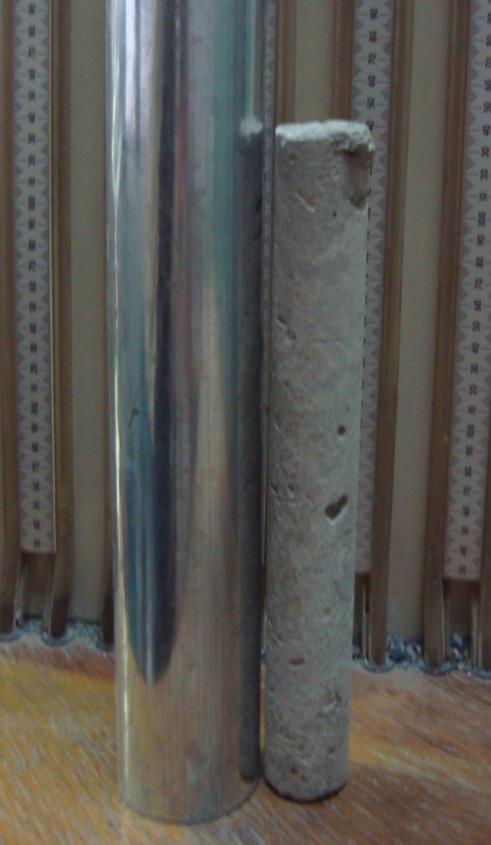
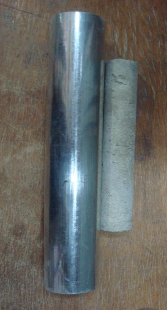
7 6. Fixing the pile tip 6.1. Literature review on fixing the pile Fixing the pile tip using cement grout presents in this work for first time. The effects of cement grout and cement treatment on soil strength, investigated by many researchers [35-36]. Fixing the piles head (no pile tip) were investigated by some researchers [41-42] Procedure of fixing the pile tip The box used for the tests is shown in Fig. 1. In order to construct a fixed pile tip in slopes, here are presented a new method, which describe below. To this end prefabricated pile, a case with larger diameter than pile element and cement slurry are needed. At first, the pile placed at the optimal location in slope and the case inserted around it (Fig. 2), then the embankment construction around case performed in multiple steps (the total height of fix end region must be divided into several smaller heights due to simplification of process). At the end of each phase the cement slurry injected into the surrounding soil through the case. It is worth mentioning that the fixed pile tip, can be implemented in one step. If a larger lateral surface of the pile tip needs to be fixed, it is recommended to implement fixing operation in several steps and lift the case in each step. For example, in order to fix the end of pile with 50 cm diameter up to 3 times of its diameter (fix end depth is 150 cm), the steps of construction divided into 3 phases. At first the pile and the case inserted in optimal location and primary 50 cm of soil layer around the case filled and after completion the cement grout poured in to the case. Then, the case pulls out approximately up to surface layer; by doing this, the cement grout in the case, radially spread and penetrate in pile surrounding soil. Then the second50 cm layer embanked and after filling completion, the cement slurry poured into case and the case removed up to near of surface in order to injection of cement slurry in surrounding soil. Afterward the second phase, 7
8 same as before, the last 50 cm of soil layer embanked and cement grout poured in the case, same as pervious, the cases pulls out and cement slurry spread in to sub soil. By reaching the intended height to create the fixed pile tip, the case removed completely and embankment performed in ordinary condition. Fig. 3 shows the process of constructing a fixed pile tip in practice. This originality in providing fix end condition in pile cause that after cement slurry treatment, a rigid and integrated zone around pile end formed (Fig. 4), which, this region cause dramatic increase in resistance against loads. In order to obtain certainty of fix-end pile performance, two experimental tests were carried out in sandy slopes; first model was reinforced slope in condition of free-end pile and the second one was reinforced slope in presence of fixed-end pile constructed by this approach. In the first model, a prefabricated pile with diameter of 3.6 cm placed in the middle of slope and embankment constructed, then after precipitation, loading process began which the critical failure stress was obtained kpa. In the second model, slope geometry, soil and pile properties were the same as first model, and a case with diameter of 5.5cm was used for provision of fix end condition. The purpose is to create a fixed pile tip with height of three times of pile diameter (10.8 cm). In order to do that, embankment layers were performed in three phases (each step with embankment height of 3.6 cm). The first layer embanked and cement slurry poured into case and the second step of embankment construction performed, after finish of second phase, the case was pulled out about 3cm in order to the cement slurry inject through surrounding soil, then next step of purring cement grout carried out. These cycles were done until the final height of fixity (10.8 cm) in end of pile reached, and then the case removed completely and same as free end pile, remained parts 8
9 of slope constructed. After precipitation, loading process began which in this condition, the critical failure stress was obtained kpa (Fig. 5). The results of this research indicate that by using this simple and effective method, which proposed in this paper, the pile end could be fixed and due to that, bearing capacity and stability of slope increase significantly. Comparing these two experimental tests, confirmed the effectiveness of fix end pile, and this model construction procedures, show the simplicity of this reinforcing mechanism. Variations of loading with displacement of pile head for free-end and fixed-end piles are shown in Figs. 6 and 7 respectively. Also, variations of loading with time for fixed-end pile is shown in Fig Numerical Examples 7.1.Example 1 The inclined surface studied in this example is depicted in Fig.9. The embankment height is equal to 13.7 m and its slope is 30 degrees. The unit weight is kn/m 3, angle of friction is 10 degrees, cohesion is equal to kn/m 2, modulus of elasticity is kn/m 2, and Poisson s ratio is Analysis of the effect of fixed pile tip The fixed pile ends method, which is introduced as a new method in this paper, can considerably change the value of the factor of safety. In two- or multi-layer slopes whose lowest layer has a proper density, the adequate reliability can be obtained by embedding the 9
10 pile end in the dense layer. However, in the case of homogenous slopes other methods proposed by some other researchers can be used for reliability purposes. Lee et al. [42] suggest that in order to achieve the reliability length (Le) the pile should be embedded in the layer below the critical slip surface to a depth equal to H (distance between the critical failure surface and the ground surface). Kourkoulis et al. [24] believe that the pile reliability length (Le) can be 5D at most. Reese and Van [30] also indicated that the effective zone on each pile beneath the critical slip surface does not exceed 5D. In Fig. 10 the critical slip surface for LE and SSR methods are shown. Fig. 11 shows the results of the comparison made between the results of the SSR method used for a free-end and fixed-end pile with a length of L=1.5H. As seen in this figure, fixing pile end has a significant effect on the growth of the factor of safety. A fixed pile end can increase the value of the factor of safety up to 55%. Fig.12 shows the results of the comparison between the results obtained by the SSR method for a row piles with a length of 1.5H and the results obtained for a row free-end piles with a length of 2H in [25]. As seen in this figure, in spite of the short length of the pile, fixing the pile end has led to a considerable increase in the value of factor of safety. Hence, by diminishing the pile length and adding to the factor of safety one of the main objectives of stabilization, i.e. cost reduction, achieved. As seen in Fig.12, the maximum factor of safety belongs to the piles that installed in the middle of the slope. According to Fig.12, which x shows that the highest factor of safety belongs to 0. 5, variations of the reliability length r (Le) below the critical slip surface are examined in proportion to the factor of safety values. 10
11 At each phase the pile reliability length (Le) is increased by 1 D. Table 1 presents the variations of pile reliability length and factor of safety. As seen in Table1, in the case of a fixed end pile, increase in Le does not significantly contribute to the increase in the factor of safety value. Due to implementation reasons, it is necessary to have a pile reliability length that makes it possible to embed the pile to a depth two times the pile diameter in the layer below the critical slip surface to ensure that the slip band will above the end of pile reliability length Determining the most effective location for pile installation The most effective location for pile installation is the place that not only gives the required factor of safety but also uses the minimum pile length. As it was described, the factor of safety in a homogenous soil can be increased significantly by fixing the pile end and reducing its length. Although the process of fixing pile end is time-consuming and necessitates precision, the resulting significant increase in factor of safety and reduction in stabilization costs are the reasons that justify it. As seen in Figs. 13 and 14, a horizontal plane can give the required factor of safety. The point the plane collides with the curve gives the coordinates of different pile lengths and locations. The place with the shortest pile length is the most effective for pile installation. 7.2.Example2 The three-layer earth slope studied in this example is depicted in Fig.15. The strength parameters of the third layer are larger than those of the other two layers. The slope height is 10 m and its angle is 34 degrees. The physical characteristics of the layers presented in Table 11
12 2. The figures of numerical analyses using SLOPW and PLAXIS programs are shown in Fig. 16. The minimum factor of safety for LE and SSR methods are calculated 0.88 and 0.75 respectively Analysis of the effect of fixed pile tip In this example the third layer, which lies at the bottom of the pile, has the largest strength parameters. Fig.17 shows the results of modeling a pile for different locations (0.1 x/r 0.8) and L=1.5H in free-end and fixed-end conditions. As seen in Fig.17, fixing the pile end does not leave a significant effect on the value of factor of safety. The reason is that emplacing the pile end into a layer with large strength x parameters is the same as fixing the pile end. As seen in Fig.17, at 0. 1 the results r obtained from fixed end pile do not very well comply with the results of the free end pile. The reason is that the length required for emplacing the pile end into the third layer is not achieved. x Fig.17 indicates that the largest factor of safety belong to Hence, the variations of r x reliability length (Le) studied based on the factor of safety of Results of the r variations of reliability length (Le) are depicted in Fig.18. As seen in this figure, in the case of the fixed end pile, increase in the reliability length does not have a significant effect on the increase in the factor of safety. However, in the case of the free end pile, increase in the pile length leads to the growth of safety factor. The maximum factor of safety is also achieved with L=H+4D and with length values higher than H+4D the factor of safety remains unchanged. The increase in the factor of safety is a result of the collision between pile end 12
13 and the dense layer. A comparison between Figs. 15 and 16 indicates that to achieve a safety factor of 1.2 for a free pile tip, it is necessary to choose a pile with a length 5D longer than the fixed pile tip. If the pile diameter is considered 1 meter, the volume of reinforced concrete will be increased by about 4 cubic meters. Given that implementation of concrete per cubic meter costs 20 dollars, 80 extra dollars will be needed for each pile. So, if there are 10 piles in a row, it will cause $ 800 extra costs Determining the most effective and economical location for pile installation As it was explained earlier if the pile end is embedded in a strong layer, fixing the pile end will not significantly increase the factor of safety (except for the pile end that is fixed in the x vicinity of slope toe). According to Fig.17, the safety of factor for 0. 4 r is equal to Figs.19 and 20 show the three-dimensional diagram of pile length (L), pile location (x/r), and factor of safety for free-end and fixed-end pile, respectively. In order to find the most effective location for pile installation the horizontal plane for the factor of safety of interest should be mapped. The most effective location is the one that requires the shortest pile length. In fact, not only the most effective location yields the required factor of safety but also provides for the shortest pile length and reduction in stabilization costs. 8. Conclusion In this paper, the minimum stabilization pile length is achieved by a new proper method. Fixing pile tip is a method that helps to reduce stabilization costs. Then the most effective location that requires the shortest length is found by mapping the three-dimensional diagram of pile length, pile location, and factor of safety. In order to obtain the maximum factor of safety for a row of 13
14 free-end piles in homogenous slopes the piles should be placedin near of slope crown or in the middle of the slope. If the piles installed in the inappropriate location and the inadequate length, the factor of safety decreased instead of being increased. Fixing pile tips in homogenous slopes can increase factor of safety up to 55%. As a result, pile length and the stabilization costs will reduce. It should be mentioned that fixing pile tips must be done with adequate care. If the end of a pile in a non-homogeneous slope emplaced into a dense layer, the required reliability length will achieve. In such cases, fixing pile tip will not significantly increase the factor of safety. However, if the pile tip embedded into soft layer, fixing pile tips can increase the safety factor up to 55%. References [1] Hajiazizi, M., Kilanehei, P., Kilanehei, F A New Method for Three Dimensional Stability Analysis of Earth Slopes, Scientia Iranica. In press (2018). [2] Ghanbari, E., Hamidi, A. Stability Analysis of Dry Sandy Slopes Adjacent to Dynamic Compaction Process, Scientia Iranica. In press (2017). [3] Zhang, G., Wang, L. Integrated analysis of a coupled mechanism for the failure processes of pile-reinforced slopes, Acta Geotechnica, 11(4), pp (2016). [4] Wang, L., Zhang, G. Progressive failure behavior of pile-reinforced clay slopes under surface load conditions, Environmental Earth Sciences, 71(12), pp (2014). [5] Xu, J., Niu, F. Safety factor calculation of soil slope reinforced with piles based on Hill s model theory, Environmental Earth Sciences, 71(8), pp (2014). [6] Xiao, S. A simplified approach for stability analysis of slopes reinforced with one row of embedded stabilizing piles, Bulletin of Engineering Geology and the Environment, pp (2016). [7] Chen, C., Xia, Y., B, V.M. Slope stability analysis by polar slice method in rotational failure mechanism, Computers and Geotechnics, 81, pp (2017). [8] Chen, L.T. Poulos, H.G. and Hull, T.S. Model tests on pile groups subjected to lateral soil movement Soils and foundation, 37(1), pp (1997). [9] Chen, C.Y. and Martin, G.R. Soil-structure interaction for landslide stabilizing piles Computers and Geotechnics, 29(5), pp (2002). [10] Liang, R. and Zeng, S. Numerical study of soil arching mechanism in drilled shafts for slope stabilization, Soils and Foundations 42(2), pp (2002). 14
15 [11] Verveckaite, N. Amsiejus, J. and Stragys, V. Stress-strain analysis in the soil sample during laboratory testing, J. of Civil Engineering and Management 13(1), pp (2007). [12] Kahyaoglu, M.R. Imancli, G. Ozturk, A.U. and Kayalar, A.S. Computational 3D finite element analyses of model passive piles, Computational Materials Science 46(1), pp (2009). [13] Kahyaoglu, M.R. Onal, O. Imançlı, G. Ozden, G. and KayalarA.S. Soil arching and load transfer mechanism for slope stabilized with piles J. of civil engineering and management 18(5) pp (2012). [14] Kourkoulis, R. Gelagoti F. Anastasopoulos I. and Gazetas, G. Hybrid method for analysis and design of slope stabilizing piles J. of geotechnical and geoenvironmental engineering, 138(1), pp (2012). [15] De Beer, E.E. and Wallays, M. Forces induced in piles by unsymmetrical surcharges on the soil round the piles. Conf. on Soil Mechanics and Foundation Engineering, Vol. 1, Spanish Society for Soil Mechanics and Foundations, Madrid, Spain, pp (1972). [16] Ito, T. and Matsui, T. Methods to estimate lateral force acting on stabilizing piles Soils and Foundations, 15(4), pp (1975). [17] Hassiotis, S. Chameau, J.L. and Gunaratne, M. Design method for stabilization of slopes with piles Geotech. Geoenviron. Eng.,123(4), pp (1997). [18] Chen, L.T. Poulos, H.G. and Hull, T.S. Model tests on pile groups subjected to lateral soil movement Soils and foundation, 37(1) pp (1997). [19] Poulos, H.G. Design of reinforcing piles to increase slope stability. Can Geotech J., 32(5) pp (1995). [20] Tschebotarioff, G.P. Foundations, retaining and earth structures, McGraw Hill, New York, (1973). [21] Fakhimi, A. Continuum Analysis 2-Dimensional-theory and user s manual BHRC publication. Iran, (2001). [22] Poulos, H.G. and Chen, L.T. Pile response due to excavation induced lateral soil movement. Geotech. Geoenviron. Eng., 123(2), pp (1997). [23] Goh, A.T.C. The, C.I. and Wong, K.S. Analysis of piles subjected to embankment induced lateral soil movements. Geotech. Geoenviron. Eng., 123(4), pp (1997). [24] Hajiazizi M, Mazaheri AR. Use of line segments slip surface for optimized design of piles in stabilization of earth slopes, International Journal of Civil Engineering, Geotechnical engineering, 13(1), (2015). [25] Xinpo, L. Xiangjun, P. Marte, and G. Siming, H. Optimal location of piles in slope stabilization by limit analysis Acta Geotechnica7 pp (2012). [26] Hassiotis, S. Chameau, J.L. and Gunaratne, M. Design method for stabilization of slopes with piles. Geotech.Geoenviron. Eng.ASCE 123(4), pp (1997). [27] Poulos, H.G. Design of slope stabilizing piles. Slope stability engineering, N. Yagi, T. Yamagami, and J.C. Jiang, eds., A. A. Balkema, Rotterdam, Netherlands. (1999). [28] Reese, L.C. Wang, S.T. and Fouse, J.L. Use of drilled shafts in stabilizing a slope. Proc., Specialty Conf. on Stability and Performance of Slopes and Embankments II (GSP 31), Vol. 2, ASCE, New York,pp (1992). [29] Johari, A. Mousavi, S. and Hooshmand Nejad, A. A seismic slope stability probabilistic model on Bishop's method using analytical approach, Scientia Iranica, 22(3), (2015). [30] Reese, L.C. and Van Impe, W.F. Single piles and pile groups under lateral loading. A. Balkema, Rotterdam, Netherlands, (2001). [31] Poulos, H.G. Analysis of piles in soil undergoing lateral movement. Soil Mech. Found. Div ASCE,99 (5) pp (1973). [32] Ashour, M. and Ardalan, H. Analysis of pile stabilized slopes based on soil pile interaction. Computers and Geotechnics, 39, pp (2012). 15
16 [33] Won, J. You, K. Jeong, S. and Kim, S. Coupled effects in stability analysis of pile-slope systems Computers and Geotechnics, 32, pp (2005). [34] Ausilio, E. Conte, E. and Dente, G. Stability analysis of slopes reinforced with piles Computers and Geotechnics, 28, pp (2001). [35] Ebadi M, Habibagahi, G. and Hataf, N. Effect of cement treatment on soil non-woven geotextile interface, Scientia Iranica A. 22(1), (2015). [36] Yildiz, M. Soganci, A.S. Improvement of the strength of soils which comprises granular pumice by injection of cement under low pressure, J. Scientia Iranica A. 22(1), (2015). [37] Wei, W.B. Three dimensional slope stability analysis and failure mechanism Ph.D. thesis, Hong Kong Polytechnic University, Hong Kong (2008). [38] Wang, M.C. Wu, A.H. and Scheessele, D.J. Stress and deformation in single piles due to lateral movement of surrounding soils Behavior of deep foundations: ASTM special technical publication, Vol. 670, Raymond Lunggren, ed., ASTM, West Conshohocken, PA, pp (1979). [39] Popescu, M.E. Landslide control by means of a row of piles, Slope Stability Engineering: Proc., Int. Conf. on Slope Stability,Thomas Telford, London, pp (1991). [40] Li, X. Pei, X. Gutierrez, M. and He, S. Optimal location of piles in slope stabilization by limit analysis, Acta Geotechnica7, pp (2012). [41] Papadopolou, M.C. and Comodromos, E.M. On the response prediction of horizontally loaded fixed-head pile groups in sands, Computers and Geotechnics, 37, (2010) [42] Lee, C.Y. Hull, T.S. Poulos, H.G. Simplified pile-slope stability analysis Computers and Geotechnics,17, pp (1995). 16
17 Table Captions: Table 1.Variations of pile reliability length and factor of safety for free-tip and fixed-tip Table 2. Shear strength parameters of earth slope in example 2 Figure Captions: Fig.1. Experimental box and piezometers panel Fig.2. Prototype of a pile, a case and the case placement around pile Fig.3. Fixed pile tip construction process: 1) Inserting the case around the pile - 2) Pouring cement slurry into the case - 3) Pulling out the case in order to injection of the cement grout in pile sub soil - 4) Next phase of pouring cement slurry in the case - 5) Next phase of pulling out the case - 6) Final removal of case and the fixed end pile creation after cement grout treatment (Brown zone is the integrated area which fix the pile tip) Fig.4. Fixed pile tip construction after treatment of cement slurry proposed in this paper Fig.5. fixed pile tip in anearth slope (Critical stress=19.85 kpa) Fig.6. Variations of loading with displacement of pile head for free-end pile Fig.7. Variations of loading with displacement of pile head for fixed-end pile Fig.8. Variations of loading with time for fixed-end pile Fig.9. Slope geometry in example 1 and Pile reliability length (Le) under critical slip surface Fig.10. Critical slip surface in LE method (Yellow line) and SSR method (Red line) Fig.11. Comparison of the SSR method (fixed-end and free-end) for L=1.5H Fig.12. Comparison of SSR method (fixed-end pile condition) with a length of 1.5H and reference [25] with a length of 2H. Fig.13. Three-dimensional diagram of free-end pile length (L), pile location(x/r) and factor of safety (FOS) in example 1 Fig.14. Three-dimensional diagram of fixed-end pile length (L), pile location(x/r) and factor of safety (FOS) in example 1 Fig.15. Three-layer earth slope geometry in example 2 Fig.16. Numerical analysis for example 2; (a) LEM, (b) FDM Fig.17. Comparison of LE and SSR methods for different locations and L=1.5H in free-end and fixed-end conditions Fig.18. Variations of pile reliability length (Le=αD) and FOS for the fixed-end and free-end pile Fig.19. Three-dimensional diagram of pile length (L), pile location (x/r), and factor of safety (FOS) for free- end pile 17
, pile location (x/r), and factor of")
18 Fig.20. Three-dimensional diagram of pile length (L), pile location (x/r), and factor of safety (FOS) for fixed-end pile Fig.1. Experimental box and piezometers panel 18
19 19


20 Fig.2. Prototype of a pile, a case and the case placement around pile 20
 Inserting the case around the pile - 2) Pouring cement slurry into the case - 3) Pulling out the case in order to injection of the cement grout in pile sub")
21 Fig.3. Fixed pile tip construction process: 1) Inserting the case around the pile - 2) Pouring cement slurry into the case - 3) Pulling out the case in order to injection of the cement grout in pile sub soil - 4) Next phase of pouring cement slurry in the case - 5) Next phase of pulling out the case - 6) Final removal of case and the fixed end pile creation after cement grout treatment (Brown zone is the integrated area which fix the pile tip) 21


22 Fig.4. Fixed pile tip construction after treatment of cement slurry proposed in this paper 22


23 Fig.5. fixed pile tip in anearth slope (Critical stress=19.85 kpa) 23
24 Fig.6. Variations of loading with displacement of pile head for free-end pile 24
25 Fig.7. Variations of loading with displacement of pile head for fixed-end pile 25
26 Fig.8. Variations of loading with time for fixed-end pile 26

27 Fig.9. Slope geometry in example 1 and Pile reliability length (Le) under critical slip surface 27
 and")
28 Total dis e-3 m Fig.10. Critical slip surface in LE method (Yellow line) and SSR method (Red line) 28
29 FOS SSRM (Fixed End) 1.2 SSRM(Free End) x/r Fig.11. Comparison of the SSR method (fixed-end and free-end) for L=1.5H 29
30 FOS x/r SSRM [25] Fig.12. Comparison of SSR method (fixed-end pile condition) with a length of 1.5H and reference [25] with a length of 2H. 30
31 Fig.13. Three-dimensional diagram of free-end pile length (L), pile location(x/r) and factor of safety (FOS) in example 1 31
, pile")
32 Fig.14. Three-dimensional diagram of fixed-end pile length (L), pile location(x/r) and factor of safety (FOS) in example 1 32

33 Fig.15. Three-layer earth slope geometry in example 2 33

34 Fig.16. Numerical analysis for example 2; (a) SLOPEW, (b) FLAC software 34
35 FO S SSR(Free End) SSR(Fixed End) LE x/r Fig.17. Comparison of LE and SSR methods for different locations and L=1.5H in free-end and fixed-end conditions 35
36 FO S Fixed End Free End α Fig.18. Variations of pile reliability length (Le=αD) and FOS for the fixed-end and free-end pile 36
37 Fig.19. Three-dimensional diagram of pile length (L), pile location (x/r), and factor of safety (FOS) for free- end pile 37
, pile location")
38 Fig.20. Three-dimensional diagram of pile length (L), pile location (x/r), and factor of safety (FOS) for fixed-end pile 38
39 Table 1.Variations of pile reliability length and factor of safety for free-tip and fixed-tip Length of pile=l H+1D H+2D H+3D H+4D H+5D FOS for Free-tip FOS for Fixed-tip Percentage of change % % % % % Table 2. Shear strength parameters of earth slope in example 2 Layer No. Cohesion (kpa) Friction Angle (Degree) Unit Weight (kn/m 3 ) Poisson's Ratio Elasticity Modulus (kn/m2) Layer Layer Layer
40 40
41 Biographies Mohammad Hajiazizi is Associate Professor of Geotechnical Engineering at Razi University, Kermanshah. He received his Ph.D in Geotechnical Engineering from Shiraz University (Supervisor: Prof. A. Ghahramani and Prof. Hataf) in Iran, and his MSc in Geotechnical Engineering from Tarbiat Modarres University (Supervisor: Prof. A. Fakhimi). His current and main research interests are: soil improvement, slope stability, tunneling and meshless methods. 41
42 Mosoud Nasiri, Ph.D student in Geotechnical Engineering from Razi University, Kermanshah, Iran. He received his M.Sc in Geotechnical Engineering from Razi University (Supervisor: Dr. M. Hajiazizi), Kermanshah, Iran. Ahmad R. Mazaheri, is an Assistant Professor of Geotechnical Engineering at Brojerd University. He received his Ph.D in Geotechnical Engineering from Razi University (Supervisor: Dr. M. Hajiazizi), Kermanshah, Iran, and his M.Sc in Geotechnical Engineering from Amirkabir University of Technology. His current and main research interests are: slope stability and soil improvement. 42
PULLOUT CAPACITY OF HORIZONTAL AND INCLINED PLATE ANCHORS IN CLAYEY SOILS
 PULLOUT CAPACITY OF HORIZONTAL AND INCLINED PLATE ANCHORS IN CLAYEY SOILS BALESHWAR SINGH Associate Professor Department of Civil Engineering Indian Institute of Technology Guwahati Guwahati 78139, India
The Design Method of Slope Stabilizing Piles: A Review
 Research Article International Journal of Current Engineering and Technology ISSN 2277-4106 2013 INPRESSCO. All Rights Reserved. Available at http://inpressco.com/category/ijcet The Design Method of Slope
A comparison of numerical algorithms in the analysis of pile reinforced slopes
 175 A comparison of numerical algorithms in the analysis of pile reinforced slopes D. V. Griffiths 1, F. ASCE, Hang Lin 2 and Ping Cao 3 1 Division of Engineering, Colorado School of Mines, Golden, Colorado,
Numerical Analysis of the Bearing Capacity of Strip Footing Adjacent to Slope
 International Journal of Science and Engineering Investigations vol. 4, issue 46, November 25 ISSN: 225-8843 Numerical Analysis of the Bearing Capacity of Strip Footing Adjacent to Slope Mohammadreza Hamzehpour
A DETAILED ANALYSIS OF SLOPE STABILITY USING FINITE ELEMENT METHOD (FEM)
") A DETAILED ANALYSIS OF SLOPE STABILITY USING FINITE ELEMENT METHOD (FEM) S. Halder 1*, M. O. Imam 2 & M. S. Basir 1 1 Department of Civil & Water Resources Engineering, Chittagong University of Engineering
A DETAILED ANALYSIS OF SLOPE STABILITY USING FINITE ELEMENT METHOD (FEM) S. Halder 1*, M. O. Imam 2 & M. S. Basir 1 1 Department of Civil & Water Resources Engineering, Chittagong University of Engineering
Effect of Placement of Footing on Stability of Slope
 Scientific Journal of Impact Factor (SJIF) : 3.134 ISSN (Print) : 2348-6406 ISSN (Online): 2348-4470 International Journal of Advance Engineering and Research Development Effect of Placement of Footing
Full Scale Model Test of Soil Reinforcement on Soft Soil Deposition with Inclined Timber Pile
 Full Scale Model Test of Soil Reinforcement on Soft Soil Deposition with Inclined Timber Pile Suheriyatna 1, L. Samang 2, M. W. Tjaronge 3 and T. Harianto 4 1 Doctoral Student, Department of Civil Engineering,
Effect of pile sleeve opening and length below seabed on the bearing capacity of offshore jacket mudmats
 NGM 2016 Reykjavik Proceedings of the 17 th Nordic Geotechnical Meeting Challenges in Nordic Geotechnic 25 th 28 th of May Effect of pile sleeve opening and length below seabed on the bearing capacity
[Gupta* et al., 5(7): July, 2016] ISSN: IC Value: 3.00 Impact Factor: 4.116
![[Gupta* et al., 5(7): July, 2016] ISSN: IC Value: 3.00 Impact Factor: 4.116](/thumbs/90/102184431.jpg "[Gupta* et al., 5(7): July, 2016] ISSN: IC Value: 3.00 Impact Factor: 4.116") [Gupta* et al., 5(7): July, 6] ISSN: 77-9655 IC Value: 3. Impact Factor: 4.6 IJESRT INTERNATIONAL JOURNAL OF ENGINEERING SCIENCES & RESEARCH TECHNOLOGY EFFECT OF DENSITY AND MOISTURE ON THE SLOPE STABILITY
[Gupta* et al., 5(7): July, 6] ISSN: 77-9655 IC Value: 3. Impact Factor: 4.6 IJESRT INTERNATIONAL JOURNAL OF ENGINEERING SCIENCES & RESEARCH TECHNOLOGY EFFECT OF DENSITY AND MOISTURE ON THE SLOPE STABILITY
Stability of Inclined Strip Anchors in Purely Cohesive Soil
 Stability of Inclined Strip Anchors in Purely Cohesive Soil R. S. Merifield 1 ; A. V. Lyamin 2 ; and S. W. Sloan 3 Abstract: Soil anchors are commonly used as foundation systems for structures requiring
Analysis of Pullout Resistance of Soil-Nailing in Lateritic Soil
 Analysis of Pullout Resistance of Soil-Nailing in Lateritic Soil B,L.A. Isaka 1, B.C. Madushanka 1 and N.H. Priyankara 1 1 Department of Civil and Environmental Engineering Faculty of Engineering University
RESPONSE OF ANCHOR IN TWO-PHASE MATERIAL UNDER UPLIFT
 IGC 29, Guntur, INDIA RESPONSE OF ANCHOR IN TWO-PHASE MATERIAL UNDER UPLIFT K. Ilamparuthi Professor and Head, Division of Soil Mechanics and Foundation Engineering, Anna University, Chennai 25, India.
Stability analysis of slopes with surcharge by LEM and FEM
 International Journal of Advanced Structures and Geotechnical Engineering ISSN 2319-5347, Vol. 04, No. 04, October 2015 Stability analysis of slopes with surcharge by LEM and FEM MD. MONIRUZZAMAN MONI,
Load-Carrying Capacity of Stone Column Encased with Geotextile. Anil Kumar Sahu 1 and Ishan Shankar 2
 Load-Carrying Capacity of Stone Column Encased with Geotextile Anil Kumar Sahu 1 and Ishan Shankar 2 1 Professor, Department of Civil Engineering, Delhi Technological University, Delhi, India (sahuanilkr@yahoo.co.in)
Finite Element Methods against Limit Equilibrium Approaches for Slope Stability Analysis
 Finite Element Methods against Limit Equilibrium Approaches for Slope Stability Analysis H. Khabbaz 1, B. Fatahi 1, C. Nucifora 1 1 Centre for Built Infrastructure Research, School of Civil and Environmental
Piles subject to excavation-induced soil movement in clay
 Piles subject to -induced soil movement in clay Des foundations soumis au mouvement du sol du a l' dans l'argile D.E.L. Ong, C.F. Leung & Y.K. Chow Centre for Soft Ground Engineering, National University
EFFECT OF CENTRAL PILE IN INCREASING THE BEARING CAPACITY OF BORED PILE GROUPS
 EFFECT OF CENTRAL PILE IN INCREASING THE BEARING CAPACITY OF BORED PILE GROUPS Mohamed M. Shahin Department of Civil Engineering, 7 th October University, Misurata,, Libya, E-mail: Mohamed_zubi@yahoo.com
GUIDE FOR SELECTING AN APPROPRIATE METHOD TO ANALYZE THE STABILITY OF SLOPES ON RECLAIMED SURFACE MINES 1
 GUIDE FOR SELECTING AN APPROPRIATE METHOD TO ANALYZE THE STABILITY OF SLOPES ON RECLAIMED SURFACE MINES 1 John J. Bowders, Jr. and Sun Chai Lee 2 Abstract: Geotechnical engineers have long Recognized the
Development of a Slope Stability Program for Transmission Towers
 Development of a Slope Stability Program for Transmission Towers *Jung-Tae Kim 1), Youngjong Sim 2), Ah-Ram Kim 3), Gye-Chun Cho 4) and Dae-Hong Kim 5) 1), 3), 4) Department of Civil and Environmental
Keywords: slope stability, numerical analysis, rainfall, infiltration. Yu. Ando 1, Kentaro. Suda 2, Shinji. Konishi 3 and Hirokazu.
 Proceedings of Slope 25, September 27-3 th 25 SLOPE STABLITY ANALYSIS REGARDING RAINFALL-INDUCED LANDSLIDES BY COUPLING SATURATED-UNSATURATED SEEPAGE ANALYSIS AND RIGID PLASTIC FINITE ELEMENT METHOD Yu.
Study on Effect of Water on Stability or Instability of the Earth Slopes
 International Research Journal of Applied and Basic Sciences 2014 Available online at www.irjabs.com ISSN 2251-838X / Vol, 8 (9): 1482-1487 Science Explorer Publications Study on Effect of Water on Stability
Modified geotextile tube a new geotextile tube for optimized retaining efficiency and dewatering rate
 Modified geotextile tube a new geotextile tube for optimized retaining efficiency and dewatering rate Hyeong-Joo Kim 1), Tae-Woong Park 2), Sung-Gil Moon 3), Hyeong-Soo Kim 4), Ri Zhang 5), and *Peter
Evaluation of Deep-Seated Slope Stability of Embankments over Deep Mixed Foundations
 Abstract Evaluation of Deep-Seated Slope Stability of Embankments over Deep Mixed Foundations Jie Han 1, Jin-Chun Chai 2, Dov Leshchinsky 3, and Shui-Long Shen 4, When embankments are constructed over
Slope stability assessment
 Engineering manual No. 25 Updated: 03/2018 Slope stability assessment Program: FEM File: Demo_manual_25.gmk The objective of this manual is to analyse the slope stability degree (factor of safety) using
Base resistance of individual piles in pile group
 th WSEAS Int. Conf. on ENVIRONMENT, ECOSYSTEMS and DEVELOPMENT, Tenerife, Spain, December 14-16, 27 111 Base resistance of individual piles in pile group MOHAMED M. SHAHIN Department of Civil Engineering
GEOSYNTHETICS ENGINEERING: IN THEORY AND PRACTICE
 GEOSYNTHETICS ENGINEERING: IN THEORY AND PRACTICE Prof. J. N. Mandal Department of Civil Engineering, IIT Bombay, Powai, Mumbai 400076, India. Tel.022-25767328 email: cejnm@civil.iitb.ac.in Module - 8
Prof. B V S Viswanadham, Department of Civil Engineering, IIT Bombay
 22 Module 5: Lecture -4 on Stability of Slopes Sudden drawdown Determination of most critical slip surface Criteria for most critical slip surface = Minimum factor of safety Trial and error approach involves
Available online at ScienceDirect. Procedia Engineering 125 (2015 )
") Available online at www.sciencedirect.com ScienceDirect Procedia Engineering 125 (2015 ) 331 337 The 5th International Conference of Euro Asia Civil Engineering Forum (EACEF-5) Effect of Area Development
Available online at www.sciencedirect.com ScienceDirect Procedia Engineering 125 (2015 ) 331 337 The 5th International Conference of Euro Asia Civil Engineering Forum (EACEF-5) Effect of Area Development
Soil-Structure Interaction of a Piled Raft Foundation in Clay a 3D Numerical Study
 388 J. Eng. Technol. Sci., Vol. 48, No. 4, 2016, 388-407 Soil-Structure Interaction of a Piled Raft Foundation in Clay a 3D Numerical Study Endra Susila 1,* & Nita Anggraini 2 1 Geotechnical Engineering
THREE DIMENSIONAL SLOPE STABILITY
 THREE DIMENSIONAL SLOPE STABILITY Timothy D. Stark, Ph.D, PE Associate Professor of Civil and Environmental Engineering University of Illinois at Urbana-Champaign 205 N. Mathews Ave. Urbana, IL 61801 (217)
GEOTEXTILE DEFORMATION ANALYSIS OF GEOSYNTHETIC CLAY LINERS WITH FEM
 Geotextile deformation analysis of Geosynthetic Clay Liners under high hydraulic heads with Finite Element Method VII International Conference on Textile Composites and Inflatable Structures STRUCTURAL
EFFECT OF COMPACTION ON THE UNSATURATED SHEAR STRENGTH OF A COMPACTED TILL
 EFFECT OF COMPACTION ON THE UNSATURATED SHEAR STRENGTH OF A COMPACTED TILL Vanapalli, S.K., Pufahl, D.E., and Fredlund, D.G. (University of Saskatchewan, Saskatoon, SK., Canada, S7N 5A9) Abstract An experimental
CHAPTER 8 SLOPE STABILITY ANALYSIS
 TM 5-818-1 / AFM 88-3. Chap. 7 CHAPTER 8 SLOPE STABILITY ANALYSIS 8-1. General. This chapter is concerned with characteristics and critical aspects of the stability of excavation slopes; methods of designing
A STUDY ON LOAD CAPACITY OF HORIZONTAL AND INCLINED PLATE ANCHORS IN SANDY SOILS
 A STUDY ON LOAD CAPACITY OF HORIZONTAL AND INCLINED PLATE ANCHORS IN SANDY SOILS BALESHWAR SINGH Associate Professor Department of Civil Engineering Indian Institute of Technology Guwahati Guwahati 78139,
DRAFT ONONDAGA LAKE CAPPING AND DREDGE AREA AND DEPTH INITIAL DESIGN SUBMITTAL H.3 STATIC SLOPE STABILITY ANALYSES
 DRAFT ONONDAGA LAKE CAPPING AND DREDGE AREA AND DEPTH INITIAL DESIGN SUBMITTAL H.3 STATIC SLOPE STABILITY ANALYSES Parsons P:\Honeywell -SYR\444576 2008 Capping\09 Reports\9.3 December 2009_Capping and
Numerical Analysis of Leakage through Geomembrane Lining Systems for Dams
 The First Pan American Geosynthetics Conference & Exhibition 25 March 2008, Cancun, Mexico Numerical Analysis of Leakage through Geomembrane Lining Systems for Dams C.T. Weber, University of Texas at Austin,
EFFECT OF RELICT JOINTS IN RAIN INDUCED SLOPE FAILURES IN RESIDUAL SOIL
 EFFECT OF RELICT JOINTS IN RAIN INDUCED SLOPE FAILURES IN RESIDUAL SOIL Neethimappiriya Tharmalingam, Student (Email: neethi_26@yahoo.com) N.W.H. Lakshamana, Student (Email: hansaka8888@yahoo.com) R.D.T.B.
Effect of characteristics of unsaturated soils on the stability of slopes subject to rainfall
 Japanese Geotechnical Society Special Publication The 15th Asian Regional Conference on Soil Mechanics and Geotechnical Engineering Effect of characteristics of unsaturated soils on the stability of slopes
Prof. B V S Viswanadham, Department of Civil Engineering, IIT Bombay
 23 Module 5: Lecture -5 on Stability of Slopes Slope stabilization methods Slope stabilization methods generally reduce driving forces, increase resisting forces, or both. Driving forces can be reduced
Transition of soil strength during suction pile retrieval
 Maritime Heritage and Modern Ports 415 Transition of soil strength during suction pile retrieval S. Bang 1, Y. Cho 2 & K. Jones 1 1 Department of Civil and Environmental Engineering, South Dakota School
PILE FOUNDATIONS CONTENTS: 1.0 Introduction. 1.1 Choice of pile type Driven (displacement) piles Bored (replacement) piles. 2.
 piles Bored (replacement) piles. 2.") PILE FOUNDATIONS CONTENTS: 1.0 Introduction 1.1 Choice of pile type 1.1.1 Driven (displacement) piles 1.1.2 Bored (replacement) piles 2.0 Analysis 2.0.1 Driving formulae 2.0.2 Soil mechanics 2.1 Piles
PILE FOUNDATIONS CONTENTS: 1.0 Introduction 1.1 Choice of pile type 1.1.1 Driven (displacement) piles 1.1.2 Bored (replacement) piles 2.0 Analysis 2.0.1 Driving formulae 2.0.2 Soil mechanics 2.1 Piles
REDISTRIBUTION OF LOAD CARRIED BY SOIL UNDERNEATH PILED RAFT FOUNDATIONS DUE TO PILE SPACING AND GROUNDWATER AS WELL AS ECCENTRICITY
 International Journal of Civil Engineering and Technology (IJCIET) Volume 9, Issue 3, March 2018, pp. 36 55, Article ID: IJCIET_09_03_005 Available online at http://http://www.iaeme.com/ijciet/issues.asp?jtype=ijciet&vtype=9&itype=3
Experimental tests for geosynthetics anchorage trenches
 Experimental tests for geosynthetics anchorage trenches Girard H. Cemagref, Bordeaux, France Briançon L Cnam, Paris, France Rey E. Cnam, Paris, France Keywords: geosynthetics, anchorage trench, full-scale
1 Introduction. 2 General Pile Analysis Features. 2.1 Pile Internal Forces and Displacements
 RSPile version 1.0 RSPile is a general pile analysis software for analyzing driven pile installation, axially loaded piles and laterally loaded piles. It is capable of computing the axial capacity for
Reinforcement with Geosynthetics
 Reinforcement with Geosynthetics GEO-SLOPE International Ltd. www.geo-slope.com 1200, 700-6th Ave SW, Calgary, AB, Canada T2P 0T8 Main: +1 403 269 2002 Fax: +1 888 463 2239 Introduction Reinforced earth
Assessment of Geotextile Reinforced Embankment on Soft Clay Soil
 Assessment of Geotextile Reinforced Embankment on Soft Clay Soil M. Siavoshnia*, F. Kalantari and A. Shakiba Corresponding author: Civil Engineering Faculty, Neyaiesh Complex, Tehran Central Branch, Islamic
GEOSYNTHETICS ENGINEERING: IN THEORY AND PRACTICE
 GEOSYNTHETICS ENGINEERING: IN THEORY AND PRACTICE Prof. J. N. Mandal Department of civil engineering, IIT Bombay, Powai, Mumbai 400076, India. Tel.022-25767328 email: cejnm@civil.iitb.ac.in Module - 7
Improvement of Granular Subgrade Soil by Using Geotextile and Jute Fiber
 International Journal of Science, Technology and Society 2015; 3(5): 230-235 Published online August 3, 2015 (http://www.sciencepublishinggroup.com/j/ijsts) doi: 10.11648/j.ijsts.20150305.12 ISSN: 2330-7412
EFFECT OF BOLT CONNECTION OF SQUARE-SHAPED GEOCELL MODEL ON PULLOUT TEST RESULTS
 EFFECT OF BOLT CONNECTION OF SQUARE-SHAPED GEOCELL MODEL ON PULLOUT TEST RESULTS Zelong XU 1, Takashi KIYOTA 2, Sam Ronald OLOYA 3, Christian HAUSSNER 3 1 Ph. D. student, Institute of Industrial Science,
Behavior of single pile adjacent to slope embedded in reinforced sand under lateral load
 Behavior of single pile adjacent to slope embedded in reinforced sand under lateral load M. A. El sawwaf Prof. of Geotechnical Engineering Faculty of Engineering, Tanta University Egypt Email: Mos.sawaf@hotmail.com
Settlement analysis of Shahid Kalantari highway embankment and assessment of the effect of geotextile reinforcement layer
 3 r d International Conference on New Developments in Soil Mechanics and Geotechnical Engineering, 28-3 June 212, Near East University, Nicosia, North Cyprus Settlement analysis of Shahid Kalantari highway
Backfill Stress and Strain Information within a Centrifuge Geosynthetic-Reinforced Slope Model under Working Stress and Large Soil Strain Conditions
 GeoCongress 2012 ASCE 2012 461 Yang, K-H., Zornberg, J.G., Liu, C-N. and Lin, H-D. (2012). Backfill Stress and Strain Information within a Centrifuge Geosynthetic-Reinforced Slope under Working Stress
THE ULTIMATE SKIN RESISTANCE OF CONCRETE PILE IN PARTIALLY SATURATED COHESIVE SOIL BY MODIFIED Β METHOD
 International Journal of Civil Engineering and Technology (IJCIET) Volume 9, Issue 10, October 2018, pp. 1882 1891, Article ID: IJCIET_09_10_187 Available online at http://www.iaeme.com/ijciet/issues.asp?jtype=ijciet&vtype=9&itype=10
This document downloaded from vulcanhammer.net vulcanhammer.info Chet Aero Marine
 This document downloaded from vulcanhammer.net vulcanhammer.info Chet Aero Marine Don t forget to visit our companion site http://www.vulcanhammer.org Use subject to the terms and conditions of the respective
EXPERIMENTAL STUDY ON PULL-OUT CAPACITY OF HELICAL PILE IN CLAYEY SOIL
 International Journal of Civil Engineering and Technology (IJCIET) Volume 8, Issue 4, April 217, pp. 1514 1521 Article ID: IJCIET_8_4_17 Available online at http://www.ia aeme.com/ijciet/issues.asp?jtype=ijciet&vtyp
LABORATORY STUDY ON THE CONSOLIDATION SETTLEMENT OF CLAY-FILLED GEOTEXTILE TUBE AND BAGS
 Journal of GeoEngineering, Vol. 6, No. 1, pp. Chew 41-45, et al.: April Laboratory 2011 Study on the Consolidation Settlement of Clay-Filled Geotextile Tube and Bags 41 LABORATORY STUDY ON THE CONSOLIDATION
THE PERFORMANCE OF STRENGTHENING SLOPE USING SHOTCRETE AND ANCHOR BY FINITE ELEMENT METHOD (FEM)
") THE PERFORMANCE OF STRENGTHENING SLOPE USING SHOTCRETE AND ANCHOR BY FINITE ELEMENT METHOD (FEM) Tri Harianto 1*, Lawalenna Samang 2, Takenori Hino 3, Fakhriyah Usman 4 and Akbar Walenna 5 1 Associate
THE PERFORMANCE OF STRENGTHENING SLOPE USING SHOTCRETE AND ANCHOR BY FINITE ELEMENT METHOD (FEM) Tri Harianto 1*, Lawalenna Samang 2, Takenori Hino 3, Fakhriyah Usman 4 and Akbar Walenna 5 1 Associate
Behaviour of a Strip Footing on Compacted Pond Ash Reinforced with Coir Geotextiles
 Behaviour of a Strip Footing on Compacted Pond Ash Reinforced with Coir Geotextiles Dr. Goutam Kumar Pothal, Dr. G. Venkatappa Rao 2 Assistant Professor, Department of Civil Engineering Indira Gandhi Institute
A STUDY ON BEARING CAPACITY OF STRIP FOOTING ON LAYERED SOIL SYSTEM
 International Conference on GEOTECHNIQUES FOR INFRASTRUCTURE PROJECTS 27 th & 28 th February 2017, Thiruvananthapuram A STUDY ON BEARING CAPACITY OF STRIP FOOTING ON LAYERED SOIL SYSTEM ANITHA K.S. PG
Undrained lateral capacity of I-shaped concrete piles
 Songklanakarin J. Sci. Technol. 39 (6), 751-758, Nov. - Dec. 2017 http://www.sjst.psu.ac.th Original Article Undrained lateral capacity of I-shaped concrete piles Suraparb Keawsawasvong and Boonchai Ukritchon
4 Slope Stabilization Using EPS Geofoam at Route 23A
 Slope Stabilization Using EPS Geofoam at Route 23A 4.1 Introduction Geofoam introduced in recent years has provided solutions to a number of engineering problems. One of these problems is the slope stability
Field tests on the lateral capacity of poles embedded in Auckland residual clay
 Proc. 18 th NZGS Geotechnical Symposium on Soil-Structure Interaction. Ed. CY Chin, Auckland Field tests on the lateral capacity of poles embedded in Auckland residual clay Peter Rodgers Mercury Bay Civil
2.2 Soils 3 DIRECT SHEAR TEST
 507 c) GT TS 50: Nonwoven needle-punched, continuous filament, polypropylene geotextile, with mass per unit area of 200 g/m 2 and thickness of 1.9mm. d) Smooth HDPE geomembrane (GM) with average thickness
Analysis of Triangle Heating Technique using High Frequency Induction Heating in Forming Process of Steel Plate
 Analysis of Triangle Heating Technique using High Frequency Induction Heating in Forming Process of Steel Plate KEYWORDS: Steel-plate forming, Induction heating, Triangle heating, Transverse shrinkage,
IGC. 50 th. 50 th INDIAN GEOTECHNICAL CONFERENCE IMPROVEMENT IN LOAD BEARING CHARACTERISTICS OF RED MUD REINFORCED WITH SINGLE GEOGRID LAYER
 50 th IGC 50 th INDIAN GEOTECHNICAL CONFERENCE 17 th 19 th DECEMBER 2015, Pune, Maharashtra, India Venue: College of Engineering (Estd. 1854), Pune, India IMPROVEMENT IN LOAD BEARING CHARACTERISTICS OF
NUMERICAL ANALYSIS OF VERTICAL UPLIFT RESISTANCE OF HORIZONTAL STRIP ANCHOR EMBEDDED IN COHESIVE FRICTIONAL WEIGHTLESS SOIL
 Proceedings of 3rd International Conference on Advances in Civil Engineering, 21-23 December 216, CUET, Chittagong, angladesh Islam, Imam, Ali, oque, Rahman and aque (eds.) NUMERICAL ANALYSIS OF VERTICAL
Effect of Foundation Embedment of PWR Structures in SSI Analysis considering Spatial Incoherence of Ground Motions
 The th World Conference on Earthquake Engineering October -7,, Beijing, China Effect of Foundation Embedment of PWR Structures in SSI Analysis considering Spatial of Ground Motions Joo-Hyung Kang and Sang-Hoon
EAT 212 SOIL MECHANICS
 EAT 212 SOIL MECHANICS Chapter 4: SHEAR STRENGTH OF SOIL PREPARED BY SHAMILAH ANUDAI@ANUAR CONTENT Shear failure in soil Drained and Undrained condition Mohr-coulomb failure Shear strength of saturated
1. Introduction. Abstract. Keywords: Liquid limit, plastic limit, fall cone, undrained shear strength, water content.
 Comparison In Undrained Shear Strength Between Low And High Liquid Limit Soils Neelu Das *1, Binu Sarma 2, Shashikant Singh 3 and Bidyut Bikash Sutradhar 4 1( Assistant Professor, Department of Civil Engineering,
Analysis of Embankments with Different Fill Materials using Plaxis-2D
 Analysis of Embankments with Different Fill Materials using Plaxis-2D A.Laxminarayana 1, M. Naresh 2 1 PG Student, Department of civil engineering, JNTUH, Hyderabad, Telangana, India 2 Assistant Professor,
Bearing Capacity Theory. Bearing Capacity
 Bearing Capacity Theory Bearing Capacity 1 Bearing Capacity Failure a) General Shear Failure Most common type of shear failure; occurs in strong soils and rocks b) Local Shear Failure Intermediate between
An Experimental Study on Variation of Shear Strength for Layered Soils
 An Experimental Study on Variation of Shear Strength for Layered Soils Mr. Hemantkumar Ronad 1 DCE, M.Tech in Geotechnical Engg. Department of Civil Engineering 1, Basaveshwar Engineering College, Bagalkot-587102.
Moisture Content Effect on Sliding Shear Test Parameters in Woven Geotextile Reinforced Pilani Soil
 International Journal of Engineering Science Invention ISSN (Online): 2319 6734, ISSN (Print): 2319 6726 Volume 2 Issue 8 ǁ August 2013 ǁ PP.10-15 Moisture Content Effect on Sliding Shear Test Parameters
Slope Stability Analysis
 Slope Stability Analysis Vivek Assist. Professor, Civil Engineering, Lovely Professional University Phagwara, India Mandeep Multani Head of dept., Civil Engineering, Lovely Professional University Phagwara,
Soil Strength and Slope Stability
 Soil Strength and Slope Stability J. Michael Duncan Stephen G. Wright @ WILEY JOHN WILEY & SONS, INC. CONTENTS Preface ix CHAPTER 1 INTRODUCTION 1 C HAPTER 2 EXAMPLES AND CAUSES OF SLOPE FAILURE 5 Examples
NUMERICAL STUDY ON STABILITY OF PLATE ANCHOR IN SLOPING GROUND
 Proceedings of the 4 th International Conference on Civil Engineering for Sustainable Development (ICCESD 2018), 9~11 February 2018, KUET, Khulna, Bangladesh (ISBN-978-984-34-3502-6) NUMERICAL STUDY ON
SUBGRADE IMPROVEMENT OF CLAYEY SOIL WITH THE USE OF GEOTEXTILES
 SUBGRADE IMPROVEMENT OF CLAYEY SOIL WITH THE USE OF GEOTEXTILES 1 Soma Prashanth Kumar, 2 Mohammed Asif T L, 3 Mane S R Rohith 1 Assistant Professor, Department of Civil Engineering, JBIET, Moinabad, (India)
LOAD TRANSFER MECHANISM IN PULL-OUT TESTS
 Technical Paper by I.M. Alobaidi, D.J. Hoare and G.S. Ghataora LOAD TRANSFER MECHANISM IN PULL-OUT TESTS ABSTRACT: This paper presents a numerical method to predict soil-geotextile interface friction parameters.
COMPARISON OF SHEAR STRENGTH PARAMETERS OF BLACK COTTON SOIL WITH EFFECT OF RELATIVE COMPACTION
 Vol-2 Issue-4 16 COMPARISON OF SHEAR STRENGTH PARAMETERS OF BLACK COTTON SOIL WITH EFFECT OF RELATIVE COMPACTION Prof. Usha k. Patel Assistant Professor, LDCE Prof. M. G. Vanza Associate Professor, LDCE
Soil-atmosphere interaction in unsaturated cut slopes
 Soil-atmosphere interaction in unsaturated cut slopes Aikaterini Tsiampousi 1, Lidija Zdravkovic 1 and David M. Potts 1 1 Imperial College London, Department of Civil and Environmental Engineering, SW7
Development of Bearing Capacity Factor in Clay Soil with Normalized Undrained Shear Strength Behavior using The Finite Element Method
 Lim ISSN 0853-2982 Jurnal Teoretis dan Terapan Bidang Rekayasa Sipil Development of Bearing Capacity Factor in Clay Soil with Normalized Undrained Shear Strength Behavior using The Finite Element Method
SSRG International Journal of Civil Engineering ( SSRG IJCE ) Volume 4 Issue 10 October 2017
 Volume 4 Issue 10 October 2017") Numerical Modelling of Building Response to Underground Tunnelling - A Case Study of Chennai Metro Abhishek Pastore* 1 Dr. Sudhir Singh Bhadauria #2 *1 PG Scholar, Department of Civil Engineering, RGPV,
Numerical Modelling of Building Response to Underground Tunnelling - A Case Study of Chennai Metro Abhishek Pastore* 1 Dr. Sudhir Singh Bhadauria #2 *1 PG Scholar, Department of Civil Engineering, RGPV,
Research Article Three-Dimensional Stability Analysis of a Homogeneous Slope Reinforced with Micropiles
 Mathematical Problems in Engineering, Article ID 864017, 11 pages http://dx.doi.org/10.1155/2014/864017 Research Article Three-Dimensional Stability Analysis of a Homogeneous Slope Reinforced with Micropiles
Advanced Foundation Engineering. Introduction
 Shahrood University of Technology Department of Geotechnical Engineering Advanced Foundation Engineering Introduction Mohsen Keramati, Ph.D. Assistant Professor 1 - Detailed Course Plan Introduction (Geotechnical
FINAL COVER VENEER STABILITY ANALYSES FOR SCA DESIGN
 DRAFT ONONDAGA LAKE SEDIMENT CONSOLIDATION AREA CIVIL & GEOTECHNICAL FINAL DESIGN 12B12BAPPENDIX L FINAL COVER VENEER STABILITY ANALYSES FOR SCA DESIGN p:\honeywell -syr\444853 - lake detail design\09
A Review on Pull-Out Capacity of Helical Anchors in Clay And Sand
 Quest Journals Journal of Architecture and Civil Engineering Volume 3 ~ Issue 6 (2017) pp: 24-32 ISSN(Online) : 2321-8193 www.questjournals.org Research Paper A Review on Pull-Out Capacity of Helical Anchors
SOIL FOUNDATION IMPROVEMENT WITH TIRE-USED TO REDUCE SETTLEMENT OF SHALLOW FOUNDATION EMBEDDED ON SATURATED DEPOK CLAY
 POLITEKNOLOGI VOL.13 NO.1 JANUARI 2014 SOIL FOUNDATION IMPROVEMENT WITH TIRE-USED TO REDUCE SETTLEMENT OF SHALLOW FOUNDATION EMBEDDED ON SATURATED DEPOK CLAY ABSTRACT PUTERA AGUNG M.A 1, SONY P 2, IMAM
Simulation Of Pneumatic Drying: Influence Of Particle Diameter And Solid Loading Ratio
 International Journal of ChemTech Research CODEN( USA): IJCRGG ISSN : 0974-4290 Vol.4, No.4, pp 1633-1641, Oct-Dec 2012 Simulation Of Pneumatic Drying: Influence Of Particle Diameter And Solid Loading
Slope Stability of Soft Clay Embankment for Flood Protection
 Research Article Slope Stability of Soft Clay Embankment for Flood Protection Vannee Sooksatra and Pawinee Jinga* Department of Civil Engineering, College of Engineering, Rangsit University, Phaholyothin
Proposed Design Graphs of Geotextile Reinforcement on Soft Clay under Various Field Conditions
 Civil Engineering Dimension, Vol. 18, No. 2, September 2016, 109-116 ISSN 1410-9530 print / ISSN 1979-570X online CED 2016, 18(1), DOI: 10.9744/CED.18.2.109-116 Proposed Design Graphs of Geotextile Reinforcement
Soil Stabilization by Using Fly Ash
 IOSR Journal of Mechanical and Civil Engineering (IOSR-JMCE) e-issn: 2278-1684,p-ISSN: 2320-334X, Volume 13, Issue 6 Ver. VII (Nov. - Dec. 2016), PP 10-14 www.iosrjournals.org Soil Stabilization by Using
Identifying Residual Soil Parameters for Numerical Analysis of Soil. Nailed Walls
 Identifying Residual Soil Parameters for Numerical Analysis of Soil Nailed Walls Atefeh Asoudeh BSc, MSc Griffith School of Engineering Science Group Griffith University Submitted in fulfilment of the
DEPTH OF EMBEDMENT OF A SHEET PILE WALL
 IJRET: International Journal of Research in Engineering and Technology eissn: 319-1163 pissn: 31-738 DEPT OF EMBEDMENT OF A SEET PILE WALL M U Jagadeesha M.E.,M.I.E.,M.I.S.T.E, Lecturer, Jimma Institute
Paper ID: GE-007. Shear Strength Characteristics of Fiber Reinforced Clay Soil. M. R. Islam 1*, M.A. Hossen 2, M. A.Alam 2, and M. K.
 Paper ID: GE-7 International Conference on Recent Innovation in Civil Engineering for Sustainable Development (IICSD-2) Department of Civil Engineering DUET - Gazipur, Bangladesh 48 Shear Strength Characteristics
vulcanhammer.net Visit our companion site
 this document downloaded from vulcanhammer.net Since 1997, your complete online resource for information geotecnical engineering and deep foundations: The Wave Equation Page for Piling Online books on
Rapid Drawdown with Multi-Stage
 1 Introduction Rapid Drawdown with Multi-Stage Stability analysis during rapid drawdown is an important consideration in the design of embankment dams. During rapid drawdown, the stabilizing effect of
International Forum on Energy, Environment Science and Materials (IFEESM 2015)
") The Comparison and Analysis of Humidity Environment between Floor and Ceiling Radiant Cooling Systems that Combined with Displacement Ventilation Kai SUN 1 a *, Chuan-hui ZHOU 1 1 College of Urban Construction,
The Comparison and Analysis of Humidity Environment between Floor and Ceiling Radiant Cooling Systems that Combined with Displacement Ventilation Kai SUN 1 a *, Chuan-hui ZHOU 1 1 College of Urban Construction,
A new test procedure to measure the soil-water characteristic curves using a small-scale centrifuge
 A new test procedure to measure the soil-water characteristic curves using a small-scale centrifuge R. M. Khanzode, Graduate Student, University of Saskatchewan, Saskatoon, Canada, S7N 5A9 D.G. Fredlund,
Behaviour of Black Cotton Soil Reinforced with Sisal Fibre
 10th National Conference on Technological Trends (NCTT09) 6-7 Nov 2009 Behaviour of Black Cotton Soil Reinforced with Sisal Fibre Santhi Krishna K. M Tech Student Department of Civil Engineering College
GEOSYNTHETICS ENGINEERING: IN THEORY AND PRACTICE
 GEOSYNTHETICS ENGINEERING: IN THEORY AND PRACTICE Prof. J. N. Mandal Department of civil engineering, IIT Bombay, Powai, Mumbai 400076, India. Tel.022-25767328 email: cejnm@civil.iitb.ac.in Module - 3