License Agreement. Trademarks and Copyright
|
|
|
- Corey Townsend
- 6 years ago
- Views:
Transcription
1
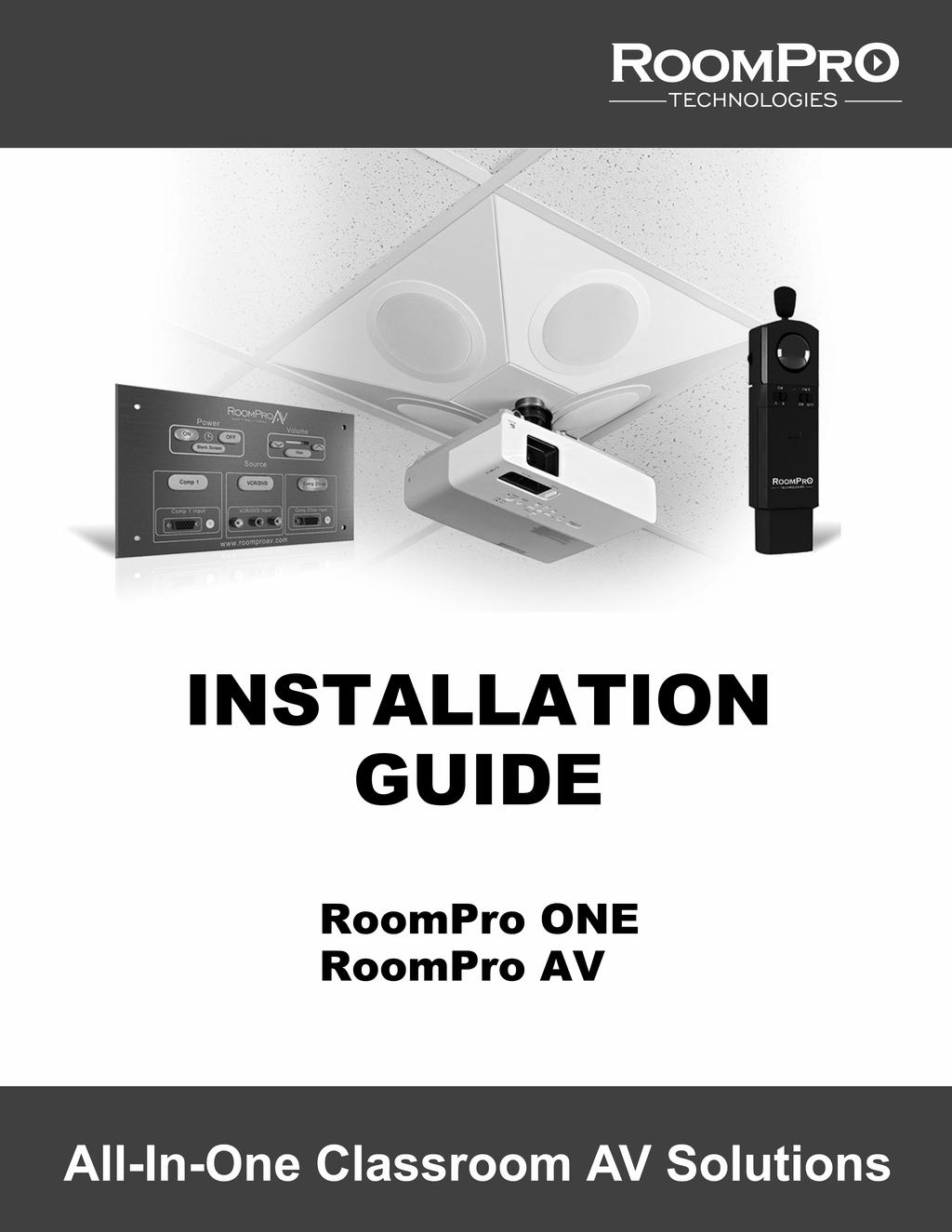
2 License Agreement This document and its contents are furnished "as is" for informational purposes only, and are subject to change without notice. Projection Guys, Inc. does not represent or warrant that any product or business plans expressed or implied will be fulfilled in any way. Any actions taken by the user of this document in response to the document or its contents will be solely at the risk of the user. PROJECTION GUYS, INC. MAKES NO WARRANTIES, EXPRESSED OR IMPLIED, WITH RESPECT TO THIS DOCUMENT OR ITS CONTENTS, AND HEREBY EXPRESSLY DISCLAIMS ANY AND ALL IMPLIED WARRANTIES OF MERCHANTABILITY, FITNESS FOR A PARTICULAR USE OR NON-INFRINGEMENT. IN NO EVENT SHALL PROJECTIONGUYS BE HELD LIABLE FOR ANY DIRECT, INDIRECT, SPECIAL OR CONSEQUENTIAL DAMAGES IN CONNECTION WITH OR ARISING FROM THE USE OF ANY PORTION OF THE INFORMATION. Copyright 2010 by Projection Guys, Inc. All rights reserved. This document may not be reproduced, photocopied, displayed, transmitted or otherwise copied, in whole or in part, in any form or by any means now known or later developed, such as electronic, optical or mechanical means, without the written agreement of Projection Guys, Inc. Any unauthorized use may be a violation of domestic or international law. Trademarks and Copyright RoomPro AV, RoomPro ONE and the RoomPro Technologies logo are trademarks of Projection Guys, Inc. All other product or company names mentioned are used for identification purposes only, and may be trademarks of their respective owners.
3 TABLE OF CONTENTS SAFETY INSTRUCTIONS... 2 INTRODUCTION... 3 About RoomPro Technologies... 3 ABOUT THIS GUIDE... 4 RoomPro Package Components... 4 Accessories... 5 System Specifications and Features... 5 INSTALLATION PLANNING... 6 Tools and Materials... 6 Site Preparation... 6 INSTALLATION... 8 Step 1: INSTALLING THE CEILING ENCLOSURE Step 2: MOUNTING THE PROJECTOR Step 3: INSTALLING THE INFRARED (IR) MICROPHONE SYSTEM Step 4: INSTALLING THE CONTROL PANEL Step 5: FINAL ASSEMBLY AND ADJUSTMENT
4 SAFETY INSTRUCTIONS To avoid potential equipment damage and/or serious injury, READ AND FOLLOW all safety precautions when installing the RoomPro system. WARNINGS are located throughout the procedural steps in this guide, and are repeated below for emphasis. USE A CERTIFIED ELECTRICAN FOR POWER CONNECTIONS. The RoomPro system uses standard 110VAC power. Obtain the services of a certified electrician when supplying and connecting power to the Ceiling Enclosure. BE SURE electrical installation complies with local building codes. Improperly installing and/or connecting power to the system may result in EQUIPMENT DAMAGE, serious INJURY and/or DEATH. DO NOT INSTALL ALONE. The Ceiling Enclosure weighs approximately 25 pounds, and requires at least two people to install. DO NOT install alone. USE SUITABLE LADDERS. Use proper ladders or support platforms when installing the RoomPro Ceiling Enclosure. DO NOT stand on chairs, tables or other unsuitable surfaces. SUPPORT THE CEILING ENCLOSURE PROPERLY. DO NOT allow the full weight of the Ceiling Enclosure to rest on the tile grid of the ceiling. The Ceiling Enclosure is designed to be suspended at FOUR POINTS by suspension wires (secured to rafters or other suitable mounting points) and to rest LIGHTLY on the tile grid. 2
5 INTRODUCTION About RoomPro Technologies Thank you for choosing RoomPro Technologies. We are a Wisconsin-based manufacturer of all-in-one classroom control and microphone solutions. Founded on the idea that classroom audio-visual technology should be teacher, installer and budget-friendly, we released RoomPro AV the industry's first projector mount with integrated speakers. That initial design led to further development of a complete audio-visual system with infrared (IR) wireless microphone: RoomPro ONE. Equipped with a built-in, two-channel IR microphone that offers optimized voice enhancement, this fully integrated solution includes all the benefits of a high-quality wireless microphone system plus a complete control system in ONE affordable package. Our solutions are engineered and built right in Wisconsin, with strong ties to the surrounding community. We proudly contract the services of the local Opportunity Development Center for product assembly, affording us the privilege of helping to provide a fundamental sense of accomplishment and pride for adults with developmental disabilities or other employment barriers. RoomPro Technologies is community-oriented and 100% customer-focused. We are dedicated to providing you with an outstanding level of service and support. And we understand successful implementation starts with successful installation. So we are pleased to offer you this step-by-step guide to a safe and successful installation. Thank you again for choosing RoomPro. Sincerely, Dean Olds President, RoomPro Technologies 3

6 ABOUT THIS GUIDE READ THIS GUIDE COMPLETELY BEFORE BEGINNING INSTALLATION. This guide provides the procedures and instructions necessary to install and operate your RoomPro ONE AV system. Be sure to follow ALL SAFETY PRECAUTIONS during installation. RoomPro Package Components The RoomPro Package includes: Ceiling speaker enclosure with integrated Hi-Fidelity speakers and 40-watt amplifier Enclosure lid with single-gang cutout and fastening screws Universal projector mount and tube adaptor Three-input user control panel (2 VGA with Audio, 1 Composite with Stereo Audio) with fastening screws Infrared (IR) pendant-style microphone with lanyard and two-pack of rechargeable batteries* IR sensor and cable* Charger for microphone and batteries* Teacher-optional behind-the-head style headset with adjustable mic boom* Two (2) 35' plenum CAT5e cables for connecting user panel to ceiling enclosure 6' projector cable pack (RS-232, VGA, Composite) 25' VGA w/audio Mounting hardware (turnbuckles, wire, and screws) * RoomPro ONE package only 4
7 Accessories Optional Accessories for the RoomPro system include: Surface-mount wall box for control panel USB Powered 2-Port VGA Video Splitter Additional IR microphone(s) with lanyard and rechargeable batteries Flush-mounting kit for solid ceilings For pricing and availability, contact RoomPro Technologies or your nearest authorized reseller. System Specifications and Features Amplifier - 40 watts Stereo at 4 Ohm Speakers - Four 5-1/4" poly woofers with butyl surround Sensitivity - 91 db Frequency Response - 50 Hz - 20,000Hz All-Metal Enclosed System - For easy above-ceiling installation 5
8 INSTALLATION PLANNING Before beginning installation, make sure that you have the necessary tools and materials on hand, and that pre-installation site preparation has been accomplished: Tools and Materials In addition to the contents of the RoomPro system, you will need the following tools and materials: Phillips head screwdriver Pliers or vice grips Wire cutters Velcro or double-sided tape Drill Utility knife 1-1/2 pipe wrench Wiremold Raceway, 500/700 series, small (see INSTALLATION Step 4 for details) Site Preparation A schematic/wiring diagram of a typical RoomPro installation is shown in Figure 1 RoomPro One Schematic/Wiring Diagram. NOTE The RoomPro Ceiling Enclosure is designed for installation in a 2 x 2 or 2 x 4 grid-type dropin ceiling. If you do not have this type of ceiling, please contact your local authorized dealer or RoomPro Technologies for a special flush mount kit. Determine the location for the Ceiling Enclosure Refer to the documentation for your projector to determine the correct distance from the display screen at which the project must be mounted. Remove the ceiling tile from this location, as well as the adjacent tiles, to provide sufficient workspace during installation. Supply power to the selected location WARNING! USE A CERTIFIED ELECTRICAN FOR POWER CONNECTIONS. The RoomPro system uses standard 110VAC power. Obtain the services of a certified electrician when supplying and connecting power to the Ceiling Enclosure. BE SURE electrical installation complies with local building codes. Improperly installing and/or connecting power to the system may result in EQUIPMENT DAMAGE, serious INJURY and/or DEATH. The RoomPro System uses standard 110VAC power. The source of this power should be considered to avoid interference with lighting and other noise possibilities. The Ceiling Enclosure lid provides a cutout for installation of a single-gang electrical box. The box should be fitted with a dual outlet; one to supply power to the Ceiling Enclosure electronics, and one to supply power to the projector. 6
9 Determine the location for the Control Panel. NOTE The Wall Panel is a low-voltage device. It does not require a separate power source. The Control Panel can be installed in-wall (flush mounted) using a standard 4-gang electrical box (not provided), or it can be surface mounted using the optional Surface Mount Wall Box. The RoomPro system is supplied with 35 Cat5 cables for connecting the Ceiling Enclosure electronics to the Control Panel. This allows the Control Panel to be installed up to 30 from the Ceiling Enclosure. If it is necessary to mount the Control Panel more than 30 from the Ceiling Enclosure, please contact your local authorized dealer or RoomPro Technologies to obtain longer cables (purchased separately). Cables of up to 150 may be used, if necessary. CEILING ENCLOSURE I AMPLIFIER POWER ADAPTOR H CEILING ENCLOSURE LID E F D A C B G CONTROL PANEL IR RECEIVER PROJECTOR A Amplifier OUTPUT VGA to Projector INPUT B Amplifier OUTPUT COMPOSITE to Projector INPUT C Amplifier OUTPUT RS-232 to Projector INPUT D Amplifier IR DOME to IR Receiver E Control Panel PORT A to Amplifier UTP INPUT PORT A F Control Panel PORT B to Amplifier UTP INPUT PORT B G Projector Power to Facility Power H Amplifier POWER +12V to Power Adaptor I Power Adaptor Power to Facility Power Figure 1 RoomPro One Schematic/Wiring Diagram 7
10 INSTALLATION Ceiling Enclosure 2. Ceiling Enclosure Lid 3. Tube Adaptor 4. Projector Mount 5. Turnbuckle (4) 6. Thread Retainer (4) 7. Eye Lag Bolt (4) 8. Suspension Wire 3 4 Figure 2 Ceiling Enclosure Installation 8
11 Source 1. Control Panel 2. Panel Screws, Black (4) 3. Wall Mount Panel 4. Concrete TapCon Screws (4) 5. Cat5 Cable, Port A 6. Cat5 Cable, Port B 7. Wiremold Raceway 500/ (purchased separately) ROOMPRO AUDIO - VIDEO - CONTROL 4 Power Volume ON OFF Blank Screen Comp 1 VCR/DVD Comp2/Doc 6 Mute 5 Comp 1 Input VCR/DVD Input Comp2/Doc Input Figure 3 - Control Panel Installation (Wall Mount Option) 9
12 Installation of the RoomPro system is accomplished in five steps: Step 1 Installing the Ceiling Enclosure Step 2 Mounting the Projector Step 3 Installing the Infrared (IR) Microphone System (RoomPro ONE system only) Step 4 Installing the Control Panel Step 5 Final Assembly and Adjustment See Figure 2 Ceiling Enclosure Installation and Figure 3 - Control Panel Installation (Wall Mount Option) for general installation requirements. Install the RoomPro system in accordance with the following procedures and your local and state codes. WARNING! DO NOT INSTALL ALONE. The Ceiling Enclosure weighs approximately 25 pounds, and requires at least two people to install. DO NOT install alone. WARNING! USE SUITABLE LADDERS. Use proper ladders or support platforms when installing the RoomPro Ceiling Enclosure. DO NOT stand on chairs, tables or other unsuitable surfaces. Step 1: INSTALLING THE CEILING ENCLOSURE 1. Select the Anchor Points NOTE The Ceiling Enclosure is designed to be suspended at FOUR SEPARATE ANCHOR POINTS (for even weight distribution) by suspension wires secured to rafters or other suitable anchoring points. NOTE The four anchoring points MUST be independent of any other systems or objects and designated exclusively for the RoomPro Ceiling Enclosure. DO NOT create any shared anchoring points. NOTE The Ceiling Enclosure has been designed with a 3 offset hole for the tube adaptor and projector mount. This provides added flexibility through the rotation of the Ceiling Enclosure when planning for optimum projector placement. Double check the Ceiling Enclosure placement to ensure the correct distance from the display screen to the lens of the projector (see projector documentation). Determine the best location for the four anchor bolts above the drop ceiling. The anchor bolts should be located roughly above the associated mounting lugs on the Ceiling Enclosure and spaced to ensure proper weight distribution. See Figure 4 Ceiling Enclosure Mounting Requirements. RIGHT WRONG Figure 4 Ceiling Enclosure Mounting Requirements 10
13 2. Install the Lag Bolts For wood beams or rafters: Screw the supplied eye lag bolts securely into the beam or rafter. See Figure 5 Lag Bolt Installation. For concrete beams or rafters: Drill a 1/4-in. diameter X 1-1/2-in. deep pilot hole at each selected anchor point. Use a hammer to tap a plastic thread retainer into each pilot hole. Handthread an eye lag bolt into each retainer, then use pliers or vice grips to tighten the bolts fully. See Figure 5 Lag Bolt Installation. LAG BOLT LAG BOLT THREAD RETAINER WOOD BEAM CONCRETE OR PLASTER BEAM Figure 5 Lag Bolt Installation 3. Connect the Suspension Wire Cut a length of suspension wire to reach from one eye lag bolt to several inches below the ceiling tile. For each eye lag bolt, insert the suspension wire through the hole in the bolt, loop the end downward, and wrap at least five turns around the main suspension wire. See Figure 6 Suspension Wire Installation. 4. Mount and Adjust the Ceiling Enclosure WARNING! SUPPORT THE CEILING ENCLOSURE PROPERLY. DO NOT allow the full weight of the Ceiling Enclosure to rest on the tile grid of the ceiling. The Ceiling Enclosure is designed to be suspended at FOUR POINTS by suspension wires (secured to rafters or other suitable mounting points) and to rest LIGHTLY on the tile grid. Have one or two helpers lift and support the Ceiling Enclosure in its proper position (slightly resting on the ceiling grid). Loosen the ends of each turnbuckle until there is minimal thread remaining in the middle. Insert the "hook" end of each turnbuckle into the appropriate mounting lugs on the Ceiling Enclosure. See Figure 7 Turnbuckle Installation. Figure 6 Suspension Wire Installation Insert the loose end of each suspension wire through the loop end of its associated turnbuckle, loop the end upward, and wrap at least five turns around the main suspension wire. Cut off any excess from the end of each suspension wire. See Figure 7 Turnbuckle Installation. Figure 7 Turnbuckle Installation 11
14 Tighten each turnbuckle to remove any slack from the suspension wires. When properly adjusted, the Ceiling Enclosure will rest lightly against the ceiling grid. Step 2: MOUNTING THE PROJECTOR 1. Install the Tube Adaptor Thread the projector mount tube adaptor into the receptacle in the bottom of the Ceiling Enclosure. Use a 1-1/2 pipe wrench to tighten the tube adaptor until secure (approximately half way into the Ceiling Enclosure). 2. Assemble the Projector Mount and Attach the Projector The projector mount comes with separate assembly and installation instructions. Refer to the instructions provided with the projector mount to assemble and secure the mount to the projector. Make sure sliding adjustment mechanism is turned to parallel or perpendicular position for leftto-right or front-to-back adjusting, depending on desired projector positioning for optimum projection. 3. Install the Projector Mount and Projector Loosen the setscrew in the projector mount collar. Thread the full projector mount assembly onto the tube adaptor until the top flange of the projector mount is secured tight to the tube adaptor. Align the projector to the projection surface (refer to your projector documentation for proper alignment). Tighten the setscrew in the projector mount collar. 4. Connect the Projector Cables NOTE The three projector cables (6' VGA, 6' serial, 6' composite) are bundled together to allow for easy routing and connection. Route the projector cable bundle through the tube adaptor. BE SURE to route the cables through one at a time. Begin with the VGA cable, followed by the serial cable, and finally the composite cable. Connect the VGA, serial and composite cables to the appropriate ports on the projector, and ensure the cables are connected securely. BE SURE to check the cable connections at the amplifier in the Ceiling Enclosure. See Figure 1 RoomPro One Schematic/Wiring Diagram. Route the projector power cable up through the tube adaptor and into the Ceiling Enclosure. Connection of the projector power cable is accomplished in Step 5. 12
15 Step 3: INSTALLING THE INFRARED (IR) MICROPHONE SYSTEM NOTE Readjustment of the IR receiver following installation may be necessary to determine the optimal mounting location. Changing the position of the receiver will have a significant effect on the range of the IR microphone. If you experience weak audio during use, reposition the receiver until satisfactory results are obtained. 1. Mount the IR Receiver Determine the desired location for the IR receiver. The receiver should be positioned so the associated cable will not interfere with projector operation, and so that the receiver is clearly visible from the location from which the microphone will be used. See Figure 8 IR Receiver Installation for possible placement options. ATTACH TO UNDERSIDE OF PROJECTOR CLIP TO CEILING GRID Figure 8 IR Receiver Installation Secure the IR receiver to the selected location using Velcro, double-sided tape, or simply clipping the receiver to the runner on the ceiling grid, depending on desired placement. 2. Connect the IR Cable For IR receiver placement on the Ceiling Enclosure or projector: Route the IR receiver cable through the tube adaptor and connect to the IR receiver. For IR receiver placement away from the Ceiling Enclosure or projector: Route the IR receiver cable up through the circular1/2-inch cutout in the Ceiling Enclosure cover and out over the ceiling to a more desirable location in the room. An optional (grey) cable is provided to support longer distances. Ensure the cable is connected securely. BE SURE to check the cable connection at the amplifier in the Ceiling Enclosure. See Figure 1 RoomPro One Schematic/Wiring Diagram. 13
16 Step 4: INSTALLING THE CONTROL PANEL WALL MOUNT OPTION 1. Select a Mounting Location Select a location within 35 feet of the Ceiling Enclosure to ensure sufficient cable length from the Ceiling Enclosure to the wall mount panel. 2. Install the Wall Mount Panel Using the wall mount panel as a template, mark the position of the four mounting holes at the desired location. Drill a 3/16-inch pilot hole for each mounting screw. Hold the wall mount panel in position, and secure in place with four concrete tapcon screws. Tighten the screws snugly. DO NOT OVERTIGHTEN. 3. Mount the Conduit (not supplied) NOTE It is recommended that you use suitable conduit to enclose the cable run from the ceiling to the Wall panel. The cutout in the top of the wall panel is specifically designed to fit Wiremold Raceway (500/700 series, small). If you do not wish to use conduit to enclose the cable run, proceed to step 4. Cut the conduit to the proper length; from the ceiling to just inside the top of the wall mount panel. Refer to the manufacturer's instructions to install the conduit. Cut a small hole in the ceiling panel above the conduit. 4. Connect the Cat5 Cables Tag or otherwise mark the end of each Cat5 cable with its correct connection point; Port A or Port B. Run each Cat5 cable through the circular1/2-inch cutout in the Ceiling Enclosure cover. Route the cables across the ceiling, through the conduit, and into the wall mount panel. BE SURE to check local and state codes for proper ceiling cable installation. Connect each Cat5 cable to its appropriate port on the rear of the control panel. Ensure the cables are connected securely. BE SURE to check the cable connections at the amplifier in the Ceiling Enclosure. See Figure 1 RoomPro One Schematic/Wiring Diagram. 5. Install the Control Panel Position the control panel (1) in place on the wall panel, and secure in place with four black 6-32 X 1/4screws. 14
17 Blank Screen AUDIO - VIDEO - CONTROL Mute FLUSH MOUNT OPTION If desired, the control panel can be "flush-mounted" using a standard 4-gang electrical box (not supplied). Install the electrical box, and any necessary conduit between the box and the Ceiling Enclosure, in accordance with local building code. Step 5: FINAL ASSEMBLY AND ADJUSTMENT 1. Secure Primary Power Source to the Top Panel The RoomPro System uses standard 110VAC power. The Ceiling Enclosure lid provides a cutout for installation of a single-gang electrical box. See INSTALLATION PLANNING for additional details. Attach and secure the single-gang electrical box to the lid of the Ceiling Enclosure. Connect the power cable for the Ceiling Enclosure amplifier to the power adaptor box (provided by a licensed electrician) in the Ceiling Enclosure. Plug the amplifier power cable and projector power cable into the dual-outlet receptacle on the Ceiling Enclosure lid. Place the Ceiling Enclosure lid on the Ceiling Enclosure and secure with supplied screws. 2. Re-Install the Ceiling Tiles Re-install all ceiling tiles removed during installation. If your ceiling uses 2 X 4 tiles, use a sharp utility knife to trim one tile to 2 X 2, and install this tile next to the Ceiling Enclosure using a 2-foot ceiling grid brace to ensure proper ceiling replacement. 3. Connect Classroom Computer to the Control Panel For laptop computers: Connect one end of the supplied VGA with Audio cable to the video and audio output jacks of the computer; then connect the other end of the VGA with Audio cable to the Computer 1 video and audio input jacks of the Control Panel. See Figure 9 Laptop Computer Connection. LAPTOP COMPUTER CONTROL PANEL Power ROOMPRO Volume ON OFF Source Comp 1 VCR/DVD Comp2/Doc Comp 1 Input VCR/DVD Input Comp2/Doc Input VGA WITH AUDIO CABLE (SUPPLIED) Figure 9 Laptop Computer Connection 15
18 Blank Screen AUDIO - VIDEO - CONTROL Mute For desktop computers: You will need a USB-powered 2-port VGA splitter (purchased separately). Connect the single-port end of the splitter to the video (monitor) output on the computer and connect the USB plug to the USB port of the computer. Next, connect the VGA cable from the computer monitor to the top port of the splitter. Then connect one end of the supplied VGA with Audio cable to the side port of the splitter and the audio output jack of the computer; connect the other end of the VGA with Audio cable to the Computer 1 video and audio input jacks of the Control Panel. See Figure 10 Desktop Computer Connection. DESKTOP COMPUTER CONTROL PANEL VGA CABLE FROM MONITOR Power ON OFF ROOMPRO Source Volume Comp 1 VCR/DVD Comp2/Doc Comp 1 Input VCR/DVD Input Comp2/Doc Input 2-PORT VGA SPLITTER (NOT SUPPLIED) VGA WITH AUDIO CABLE (SUPPLIED) Figure 10 Desktop Computer Connection 4. Test the Installation Turn the system on at the Control Panel; wait for the projector to fully warm up. Make any necessary realignment or adjustment to the projector to achieve desired projection. Test the installation by selecting the different buttons on the Control Panel. Consult the table below to verify button selection and corresponding projector command. Control Panel Power On Power Off Freeze (Virtual Control Panel Only) Comp 1 Input VCR/DVD Input Comp 2/Doc Input Projector Command Projector On Projector Off Projector Freeze Screen (If available) VGA (Computer) 1 Source Composite Video Source VGA (Computer) 1* Source *Switching between the two VGA Inputs on the Panel is done within the RoomPro system resulting in only one VGA source being used at the projector. Power the system off and repeat. 16
19
UMA-1020 Light Weight Suspended Ceiling Kit
 INSTALLATION INSTRUCTIONS UMA-1020 Light Weight Suspended Ceiling Kit The provides a sturdy support for LCD/DLP hanging brackets (and certain other products weighing less than 50 pounds) when installing
CMA-440 Light Weight Suspended Ceiling Kit
 INSTALLATION INSTRUCTIONS CMA-440 Light Weight Suspended Ceiling Kit The provides a sturdy support for LCD/DLP hanging brackets (and certain other products weighing less than 50 pounds) when installing
CRESTRON MEDIAMANAGER INTELLICLASS
 CRESTRON MEDIAMANAGER INTELLICLASS Crestron IntelliClass systems provide educators with a simplified yet comprehensive classroom presentation solution that saves time and money. Designed to deliver the
Installation Instructions. For the 18 Built-In Dishwasher and Front Color Panels
 Installation Instructions For the 18 Built-In Dishwasher and Front Color Panels Printed in USA 154232102 Before You Begin DO NOT INSTALL DISHWASHER UNTIL YOU HAVE READ ALL INSTRUCTIONS. FOR YOUR SAFETY,
EW25 EW30 EW35 USER & INSTALLATION MANUAL. Model. Model. Model
 ON-WALL SPEAKERS Model EW25 Model EW30 Model EW35 USER & INSTALLATION MANUAL Introduction Congratulations on your purchase of an EMP Tek EW25, 30 or 35 on-wall Speaker! Your speaker is the result of many
Owner s Guide and Installation Manual Manual De Propietario
 Concert Breeze Owner s Guide and Installation Manual Manual De Propietario English Español Form# 45049-01 20090713 2009 Hunter Fan Co. For Your Records and Warranty Assistance For reference, also attach
Access Point Mounting Instructions
 Published: November 8, 010 Revised: November 9, 011 Contents Introduction, page 1 Mounting Hardware, page 1 Mounting an Access Point Below a Suspended Ceiling, page 5 Mounting an Access Point on a Hard
Installation Manual PS-200 & PS-201
 Installation Manual PS-200 & PS-201 Table of Contents Pre-Uncrating Checklist... 1 Verifying System Requirements... 2 Verifying System Direction... 2 Verifying the Electrical Requirements... 2 Removal
4545 E Baseline Rd Phoenix AZ Phone: (602) Fax: (602) MODEL MP42B/MODEL MP42W Owners Manual
 Fax: (602) MODEL MP42B/MODEL MP42W Owners Manual") 4545 E Baseline Rd Phoenix AZ 85040 Phone: (602)438-4545 Fax: (602)438-8692 MODEL MP42B/MODEL MP42W Owners Manual CONGRATULATIONS...on your purchase of MTX multi-purpose loudspeakers. Your new loudspeakers
4545 E Baseline Rd Phoenix AZ 85040 Phone: (602)438-4545 Fax: (602)438-8692 MODEL MP42B/MODEL MP42W Owners Manual CONGRATULATIONS...on your purchase of MTX multi-purpose loudspeakers. Your new loudspeakers
Installation Manual PS-225 & PS-275
 Installation Manual PS-225 & PS-275 Table of Contents Pre-Uncrating Checklist... 1 Verifying System Requirements... 2 Verifying System Direction... 2 Verifying the Electrical Requirements... 2 Removal
PROFESSIONAL SERIES IN-CEILING PS-C63RT. Introducing the Sonance Professional Series. Features & Benefits. Applications SONANCE PROFESSIONAL SERIES 1
 PROFESSIONAL SERIES IN-CEILING SPEAKER PS-C63RT Introducing the Sonance Professional Series From Sonance, the company that created the architectural audio category comes a range of professional loudspeakers
Installation and Operation Manual For Hunter Ceiling Fans
 Installation and Operation Manual For Hunter Ceiling Fans 1 2 CONGRATULATIONS! Your new Hunter ceiling fan is an addition to your home or office that will provide comfort and performance for many years.
INSTALLATION AND OPERATING INSTRUCTIONS. For Reliance Controls Emergency Power Transfer Switch Kit Model Number 30216BRK
 INSTALLATION AND OPERATING INSTRUCTIONS For Reliance Controls Emergency Power Transfer Switch Kit Model Number 30216BRK Congratulations on your purchase of the Reliance Controls Generator Power Transfer
PROFESSIONAL SERIES IN-CEILING PS-C43RT. Introducing the Sonance Professional Series. Features & Benefits. Applications SONANCE PROFESSIONAL SERIES 1
 PROFESSIONAL SERIES IN-CEILING SPEAKER PS-C43RT Introducing the Sonance Professional Series From Sonance, the company that created the architectural audio category comes a range of professional loudspeakers
EVID-S Surface Mount 12 Subwoofers
 EVID-S Surface Mount 12 Subwoofers EVID-S12.1B EVID-S12.1W en Installation manual en 3 Table of contents 1 Safety 4 1.1 Suspension 4 1.2 Notices 4 2 Introduction 5 2.1 System features 5 2.2 Product information
SUTTON 52 CEILING FAN
 SUTTON 52 CEILING FAN MODELS #50188, 50189, 50190 Español p. 19 Questions, problems, missing parts? Before returning to your retailer, call our customer service department at 1-877-361-3883, Monday - Thursday,
DUVAL 52 CEILING FAN MODELS #50201, Español p. 19 LISTED FOR DAMP LOCATION
 DUVAL 52 CEILING FAN MODELS #50201, 50206 Español p. 19 LISTED FOR DAMP LOCATION Questions, problems, missing parts? Before returning to your retailer, call our customer service department at 1-877-361-3883,
Premium Cabinet Loudspeakers. Installation manual
 Premium Cabinet Loudspeakers en Installation manual Premium Cabinet Loudspeakers Table of Contents en 3 Table of contents 1 Safety 4 1.1 Suspension 4 1.2 Notices 4 2 Short information 5 3 Introduction
36 & 48 E-Z Cone Fan. Installation & Operator s Instruction Manual (Direct Drive)
") 36 & 48 E-Z Cone Fan Installation & Operator s Instruction Manual (Direct Drive) September 1997 MV1433C Chore-Time Warranty Chore-Time Equipment warrants each new product manufactured by it to be free
36 & 48 E-Z Cone Fan Installation & Operator s Instruction Manual (Direct Drive) September 1997 MV1433C Chore-Time Warranty Chore-Time Equipment warrants each new product manufactured by it to be free
ST. KITTS CEILING FAN
 ITEM #0845047 ST. KITTS CEILING FAN MODEL #40829 Questions, problems or missing parts? Before returning this item to your retailer, call our customer service department at 1-800-643-0067, Monday - Thursday,
Electric Space Heater
 The Choice of Professionals Model No. FUH Series Electric Space Heater Installation & Maintenance Instructions SPECIFICATIONS: FUH 54B Heater Rating and Voltage 5000 W @ 40V 465W @ 40V 333W @ 40V 500W
ANYWHERE. U.S. Patent(s) Pending INSTRUCTION MANUAL WARRANTY CERTIFICATE
 Pending INSTRUCTION MANUAL WARRANTY CERTIFICATE") TM ANYWHERE BY U.S. Patent(s) Pending INSTRUCTION MANUAL WARRANTY CERTIFICATE 2017 Minka Lighting Inc. Manual design and all elements of manual design are protected by United States Federal and/or State
TM ANYWHERE BY U.S. Patent(s) Pending INSTRUCTION MANUAL WARRANTY CERTIFICATE 2017 Minka Lighting Inc. Manual design and all elements of manual design are protected by United States Federal and/or State
Owner s Guide and Installation Manual
 For Your Records and Warranty Assistance For reference, also attach your receipt or a copy of your receipt to the manual. Model Name Type 8 Models Owner s Guide and Installation Manual Model No. Catalog
USER MANUAL. Galil 8-C Closed-back Ceiling Speakers MODEL: P/N: Rev 2
 KRAMER ELECTRONICS LTD. USER MANUAL MODEL: Galil 8-C Closed-back Ceiling Speakers P/N: 2900-300345 Rev 2 Contents 1 Introduction 1 2 Getting Started 2 2.1 Achieving the Best Performance 2 2.2 Recycling
TOUCHDOWN 48 CEILING FAN
 TOUCHDOWN 48 CEILING FAN MODEL #50205 Español p. 20 Questions, problems, missing parts? Before returning to your retailer, call our customer service department at 1-877-361-3883, Monday - Thursday, 8 am
Bravo II. High Performance Multi-Purpose Speaker
 Bravo II High Performance Multi-Purpose Speaker Specifications Frequency Response (±3dB) Recommended Amplifier Power Nominal Impedance Sensitivity [1 watt (2.83v) at 1m] Bass Unit Tweeter Crossover Frequency
BUILT-IN DISHWASHER INSTALLATION INSTRUCTIONS
 BUILT-IN DISHWASHER INSTALLATION INSTRUCTIONS PLEASE READ COMPLETE INSTRUCTIONS BEFORE YOU BEGIN LEAVE INSTALLATION INSTRUCTIONS AND USER'S GUIDE WITH OWNER ALL ELECTRIC WIRING AND PLUMBING MUST BE DONE
KRAMER ELECTRONICS LTD. USER MANUAL MODEL: SPK-W611 Multipurpose Speakers. P/N: Rev 2
 KRAMER ELECTRONICS LTD. USER MANUAL MODEL: SPK-W611 Multipurpose Speakers P/N: 2900-300116 Rev 2 Contents 1 Introduction 1 2 Getting Started 2 2.1 Achieving the Best Performance 2 3 Overview 3 3.1 Defining
DSUB Collection Manual DSUB COLLECTION DSUB6F68K DSUB6F5K DSUB6F3K DSUB8F8K. DSUB Collection Installation Manual
 DSUB COLLECTION DSUB6F68K DSUB6F5K DSUB6F3K DSUB8F8K 1 DSUB Collection Installation Manual Table of Contents Introduction 1 Specifications 2 What s Included 3 Tools & Items 3 Wire Recommendation 3 Planning
Owner s Guide and Installation Manual
 For Your Records and Warranty Assistance For reference, also attach your receipt or a copy of your receipt to the manual. Model Name Type 2 Models Owner s Guide and Installation Manual Model No. Catalog
Model: EF34. Owner's Guide & Installation Manual
 Owner's Guide & Installation Manual WARNING: Read this manual before using this product. Failure to follow the instructions and safety precautions in this manual can result in damage to property, serious
MAYFIELD CEILING FAN LISTED E ITEM # MODEL #BTH44ABZC5C BTH44BNK5C Español p. 20 ATTACH YOUR RECEIPT HERE.
 Harbor Breeze is a registered trademark of LF, LLC. All Rights Reserved. ITEM #0331094 0331096 MAYFIELD CEILING FAN MODEL #BTH44ABZC5C BTH44BNK5C Español p. 20 ATTACH YOUR RECEIPT HERE Serial Number Purchase
Feniex Hammer S Distributed By: Feniex Hammer Instruction Manual / feniex.com
 Feniex Hammer Instruction Manual Feniex Hammer S-3017 Distributed By: Feniex Product Copyrights This price List and the mentioned Feniex products include or describe copyrighted Feniex material. Laws in
AO-520 & AO-620. OUTDOOR SPEAKERS I n s t a l l a t i o n & O p e r a t i o n M a n u a l
 AO-520 & AO-620 OUTDOOR SPEAKERS I n s t a l l a t i o n & O p e r a t i o n M a n u a l Introduction Congratulations on your purchase of RBH Sound outdoor speakers! Your speakers are the result of many
PROFESSIONAL SERIES IN-CEILING LOW PROFILE SPEAKER PS-C43RTLP
 PROFESSIONAL SERIES IN-CEILING LOW PROFILE SPEAKER PS-C43RTLP Introducing the Sonance Professional Series From Sonance, the company that created the architectural audio category comes a range of professional
Custom Series In-Wall and In-Ceiling Loudspeakers
 O W N E R ' S M A N U A L Custom Series In-Wall and In-Ceiling Loudspeakers Congratulations on your purchase of Custom Series In-Wall loudspeaker system and thank you for your selection of Parasound. Custom
TURBO Fiberglass Cone Fan and Grill Fan 48'' Belt Drive. Installation & Operator s Instruction Manual
 TURBO Fiberglass Cone Fan and Grill Fan 48'' Belt Drive Installation & Operator s Instruction Manual July 1998 MV1383B Chore-Time TURBO TM Fan Extended Warranty Chore-Time Equipment warrants new TURBO
Contents. Instructions for: The Outdoor Speakers by Henry Kloss
 Instructions for: The Outdoor Speakers by Henry Kloss Contents Introduction... 1 Unpacking The System... 2 Wiring And Connections... 3 Mounting... 4 Listening Levels And Amplifier Power... 5 7-Year Limited
Owner s Guide and Installation Manual
 For Your Records and Warranty Assistance For reference, also attach your receipt or a copy of your receipt to the manual. Model Name Type 2 Models Owner s Guide and Installation Manual Model No. Date Purchased
ITEM # , , PAWTUCKET CEILING FAN MODEL #40958, 40959, 40047
 ITEM #0803775, 0721899, 0807427 PAWTUCKET CEILING FAN MODEL #40958, 40959, 40047 Harbor Breeze is a registered trademark of LF, LLC. All Rights Reserved. Español p. 20 ATTACH YOUR RECEIPT HERE Serial Number
installation and operation manual for Hunter Ceiling Fans
 For Your Records and Warranty Assistance Model Name: Catalog/Model No.: Serial No.: Date Purchased: Where Purchased: For reference also attach your receipt or a copy of your receipt to the manual. installation
SPRINGHILL 44 CEILING FAN
 SPRINGHILL 44 CEILING FAN MODELS #50184, 50185 Español p. 20 Questions, problems, missing parts? Before returning to your retailer, call our customer service department at 1-877-361-3883, Monday - Thursday,
Lifetime Limited Warranty
 Hampton Bay Lifetime Limited Warranty The retailer warrants the fan motor to be free from defects in workmanship and material present at time of shipment from the factory for a lifetime after the date
Sentry LIQUID LEVEL ALARM MODEL 100 OPERATING MANUAL.
 Sentry LIQUID LEVEL ALARM MODEL 100 OPERATING MANUAL www.aquaticsentry.com TABLE OF CONTENTS 1. SAFETY PRECAUTIONS... 3 2. APPLICATION... 3 2.1 HIGH Liquid Level Alarm 2.2 LOW Liquid Level Alarm 3. INSTALLATION...
ELSTON 52 CEILING FAN
 ELSTON 52 CEILING FAN MODEL #10290 Español p. 21 Questions, problems, missing parts? Before returning to your retailer, call our customer service department at 1-877-361-3883, Monday - Thursday, 8 am -
Installation Instructions
 Installation Instructions For the 18" Built-In Dishwasher Sears, Roebuck and Co. Sears Canada, Inc. Hoffman Estates, IL 60179 U.S.A. Toronto, Ontario, Canada M5B 2B8 154435201 Before You Begin DO NOT INSTALL
UB1 AIR CONDITIONING UNIT INSTALLATION INSTRUCTIONS
 UB1 AIR CONDITIONING UNIT INSTALLATION INSTRUCTIONS INSTALLATION INSTRUCTIONS: Carefully read these instructions before installing your new air-conditioner. AUSTRALIAN AUTOMOTIVE AIR AL00500054E 1 Table
IWTS Series IWTS-5 LCR & IWTS-10 LCR In-Wall Theater System Speakers. Instruction Manual
 IWTS-5 LCR IWTS Series IWTS-5 LCR & IWTS-10 LCR In-Wall Theater System Speakers IWTS-10 LCR Instruction Manual 2 Safety Precautions Table of Contents 2 Model IWTS-5 LCR & IWTS-10 LCR 3 Important Considerations
Owner s Manual LIMITED WARRANTY INFORMATION OBTAINING WARRANTY SERVICE FURTHER LIMITATIONS AND EXCLUSIONS ARE AS FOLLOWS REGISTRATION
 LIMITED WARRANTY INFORMATION Your DUCT PURE (Product) is warranted to be free from all defects in material and workmanship in normal household use for a period of 2 Years from date of purchase. The warranty
PROFESSIONAL SERIES PENDANT SPEAKER PS-P63T
 PROFESSIONAL SERIES PENDANT SPEAKER PS-P63T Introducing the Sonance Professional Series From Sonance, the company that created the architectural audio category comes a range of professional loudspeakers
CEILING SPEAKER SYSTEM
 INSTRUCTION MANUAL CEILING SPEAKER SYSTEM F-2852C TABLE OF CONTENTS 1. SAFETY PRECAUTIONS... 2 2. GENERAL DESCRIPTION... 3 3. FEATURES... 3 4. NOMENCLATURE AND DIMENSIONS... 4 5. INSTALLATION... 5 7. REPAINTING
BAY BRIDGE CEILING FAN
 Harbor Breeze is a registered trademark of LF, LLC. All Rights Reserved. ITEM #0451817 BAY BRIDGE CEILING FAN MODEL #CPJ1240 Español p. 19 ATTACH YOUR RECEIPT HERE Serial Number Purchase Date Questions,
Installation GUIDE VDWU524SS VDWU524WSSS FDWU524WS FDWU524 VDWU324SS FDWU324
 Installation GUIDE VDWU524SS VDWU524WSSS FDWU524WS FDWU524 VDWU324SS FDWU324 To prevent accidents, which could cause serious injury or death, as well as machine damage read these instructions before installation
Owner s Guide and Installation Manual
 For Your Records and Warranty Assistance For reference, also attach your receipt or a copy of your receipt to the manual. Model Name Type 2A Models Owner s Guide and Installation Manual Model No. Date
ITEM # , CARATUK RIVER CEILING FAN MODEL #40046, 40303
 ITEM #0833928, 0807428 CARATUK RIVER CEILING FAN MODEL #40046, 40303 Harbor Breeze is a registered trademark of LF, LLC. All Rights Reserved. Español p. 21 ATTACH YOUR RECEIPT HERE Purchase Date Questions,
Installation Guide. For Models: E-DCF52BNK5C3 E-DCF52FBZ5C3 E-DCF52MWW5C3 READ THESE INSTRUCTIONS AND SAVE THEM FOR FUTURE USE
 READ THESE INSTRUCTIONS AND SAVE THEM FOR FUTURE USE Federal regulations require ceiling fans with light kits manufactured or imported after January 1, 2009, to limit total wattage consumed by the light
INSTALLATION INSTRUCTIONS. WOOD BLINDS 1-3/8, 2 and 2-3/8 SLAT SIZES. COMPOSITE FAUX WOOD BLINDS 2 and 2-1/2 SLAT SIZES
 INSTALLATION INSTRUCTIONS WOOD BLINDS 1-3/8, 2 and 2-3/8 SLAT SIZES COMPOSITE FAUX WOOD BLINDS 2 and 2-1/2 SLAT SIZES POLYMER FAUX WOOD BLINDS 2 and 2-1/2 SLAT SIZES STANDARD CORDLESS LIFT Thank you for
30-YEAR LIMITED WARRANTY
 PROGRESS LIGHTING 30-YEAR LIMITED WARRANTY PROGRESS LIGHTING FAN MOTORS ARE WARRANTED TO THE END USER TO BE FREE OF ELECTRICAL AND/OR MECHANICAL DEFECTS FOR A PERIOD OF 30 (THIRTY) YEARS FROM DATE OF SALE.
Owner s Guide and Installation Manual
 For Your Records and Warranty Assistance For reference, also attach your receipt or a copy of your receipt to the manual. Model Name Type 2A Models Owner s Guide and Installation Manual Model No. Date
CPL Series Pedestal Convection Heater
 Installation Instructions and RENEWAL PARTS IDENTIFICATION CPL Series Pedestal Convection Heater MODEL CPLAS (H=5-1/2, D=3 ) CAT. LENGTH WATTS/ TOTAL AMPERAGE NO.* L Ft. WATTS 120V 208V 240V 277V 2125
PAL-80, PAL-65, PAL-45 Precision Architectural Loudspeakers
 O W N E R ' S M A N U A L PAL-80, PAL-65, PAL-45 Precision Architectural Loudspeakers www.parasound.com 1 Introduction Congratulations on your purchase of this Precision Architectural Loudspeaker system
Installation Guide. For Models: E-PD52ABZ5C4 E-PD52BP5C4 E-PD52WW5C4 READ THESE INSTRUCTIONS AND SAVE THEM FOR FUTURE USE
 READ THESE INSTRUCTIONS AND SAVE THEM FOR FUTURE USE Federal regulations require all ceiling fans with light kits manufactured or imported after January 1, 2009, to limit total wattage consumed by the
ITEM # BUILDER S SERIES CEILING FAN MODEL #41391
 Harbor Breeze Harb or Breeze ITEM #0915543 BUILDER S SERIES CEILING FAN MODEL #41391 Harbor Breeze is a registered trademark of LF, LLC. All Rights Reserved. Español p. 18 ATTACH YOUR RECEIPT HERE Purchase
HT300 HT400LCR. owner's manual. analog and digital systems
 HT300 HT400LCR owner's manual analog and digital systems table of contents introduction 1 cautions 1 speaker placement 2 center channel 2 main speaker separation 2 connections 3 wire 3 connecting the speakers
Detection System Model 3500 Series
 Detection System Model 3500 Series Architect/Contractor Information Package 3M Library Systems 3M Center, Building 225-4N-14 St. Paul, Minnesota 55144-1000 Copyright 2001-2006 3M. All rights reserved.
Introduction 3. Features and Benefits 3. Parts Guide 4. Installation Considerations 4. Installing the Loudspeaker 6
 C e i l i n g M o u n t L o u d s p e a k e r s Installation Guide TM Un c o m p ro m i s i n g In Ev e ry Se n s e CONGRATULATIONS! Thank you for choosing ICS Loudspeakers. With proper installation, use,
ARMITAGE CEILING FAN ITEM # MODEL #CC52WW5L. Español p. 17 ATTACH YOUR RECEIPT HERE. Purchase Date
 ITEM #0807426 ARMITAGE CEILING FAN MODEL #CC52WW5L Harbor Breeze is a registered trademark of LF, LLC. All Rights Reserved. Español p. 17 ATTACH YOUR RECEIPT HERE Purchase Date 4009654 Questions, problems,
User s Manual and Operating Instructions
 User s Manual and Operating Instructions Model Numbers: CL-30P-DDF, CL-20F-DDF, CL-24O-DDF, CL-30-DDF READ AND SAVE THESE INSTRUCTIONS IMPORTANT: Read and understand all of the directions in this manual
OWNER S MANUAL
 OWNER S MANUAL www.airknightiaq.com THANK YOU for your purchase of the Air Knight IPG in-duct air purification system. This unit is designed to be installed into a central HVAC system and provide virtually
TILGHMAN CEILING FAN. LISTED For Damp Location E ITEM # MODEL #WCK52LMW5N WCK52NWZ5N. Español p. 20 ATTACH YOUR RECEIPT HERE
 ITEM #0294980 0294981 TILGHMAN CEILING FAN Harbor Breeze is a registered trademark of LF, LLC. All Rights Reserved. MODEL #WCK52LMW5N WCK52NWZ5N Español p. 20 ATTACH YOUR RECEIPT HERE Serial Number Purchase
Installation Instructions
 Dear customer! Thank you for choosing this quality product from ASKO. We hope it will meet your expectations and fulfil your needs for many years to come. Scandinavian design combines clean lines, everyday
Installation Instructions Fascia for Dual Roller FlexShade by Draper
 Installation Instructions Fascia for Dual Roller FlexShade by Draper Caution 1 Inspect all boxes to make sure you have received the proper shades and parts. Controls may be shipped separately, or in same
The Extraordinaire OWNER S MANUAL. Orbital Ceiling Fan. Model No. OF110** READ AND SAVE THESE INSTRUCTIONS. Net Weight 14.5 lbs. or 6.59 kg.
 The Extraordinaire Orbital Fan WARNING: Support Directly From Building Structure Net Weight 14.5 lbs. or 6.59 kg. Model No. OF110** OWNER S MANUAL READ AND SAVE THESE INSTRUCTIONS Important Safety Instructions
S - SERIES IN-WALL SERIES INSTALLATION MANUAL
 S - SERIES IN-WALL SERIES INSTALLATION MANUAL VERSION 2.2 [Skriv tekst] S-15 AND S210... 4 IN-WALL SERIES, S-15IW AND S-16IW... 13 S-15IW AND S-16IW WITH GRILLS... 38 IN-CEILING S-16IW... 64 2 INTRODUCTION
EXPANDABLE 0.5W LED FRESHWATER LIGHT FIXTURES
 INSTALLATION & MAINTENANCE GUIDE EXPANDABLE 0.5W LED FRESHWATER LIGHT FIXTURES Item # Product Description 420269 Light 20 IN 0.5W X 8W Freshwater 420270 Light 24 IN 0.5W X 9.6W Freshwater 420271 Light
2013 PINNACLE LOUDSPEAKERS
 Owner s Manual 2013 PINNACLE LOUDSPEAKERS We appreciate your choosing a Pinnacle speaker for use in your Home Theater / Audio system. This unique speaker will provide you with surprisingly powerful and
MaxLite 4, 6, 8 & 9 LED Architectural & Commercial Downlights
 General Safety Information To reduce the risk of death, personal injury or property damage from fire, electric shock, falling parts, cuts/abrasions, and other hazards read all warnings and instructions
Installation Instructions
 GE Consumer & Industrial Appliances Installation Instructions Junction Box Cover Within this user bag, you will find a junction box cover and a #10 hex head screw used to attach the junction box cover
WaterVue Bluetooth Bathroom Music System
 WaterVue Bluetooth Bathroom Music System User Manual Quick reference guide 1. Important safety instruction............................................ 2 2. Ceiling speaker / in-wall speaker.......................................
SI-744 IN-WALL SURROUND SPEAKER. O w n e r s M a n u a l
 SI-744 IN-WALL SURROUND SPEAKER O w n e r s M a n u a l Introduction Congratulations on your purchase of the RBH Sound SI-744 In-wall Surround speaker! Your speaker is the result of many years of research
Revel. M10 Owner s Manual
 Revel M10 Owner s Manual Revel Concerta M10 Owner s Manual Table of Contents 3 Introduction 4 Planning Your System 4 Placement 4 Installation 5 Tabletop/Shelf Placement Assembly 8 Wall-Mounting the M10,
OWNER S MANUAL MUSICA SERIES DISTRIBUTED AUDIO CUSTOM SPEAKERS MTX.COM
 OWNER S MANUAL MUSICA SERIES DISTRIBUTED AUDIO CUSTOM SPEAKERS Thank you for choosing MTX MUSICA Series speakers for your home audio system. Properly installed and operated, these speakers will provide
User s Guide Wireless Doorbell for IWATCHALARM (Add-On) Model: SM-105DB
 Model: SM-105DB") User s Guide Wireless Doorbell for IWATCHALARM (Add-On) Model: SM-105DB Copyright 2016 This manual is furnished under license and may be used or copied only in accordance with the terms of such license.
User s Guide Wireless Doorbell for IWATCHALARM (Add-On) Model: SM-105DB Copyright 2016 This manual is furnished under license and may be used or copied only in accordance with the terms of such license.
2010 Sedona Series Components
 LIMITED 90-DAY CONSUMER WARRANTY LIMITED TWO-YEAR CONSUMER WARRANTY WITH PURCHASE AND INSTALLATION BY A PRECISION POWER AUTHORIZED DEALER Precision Power promises to the original purchaser, to repair or
DC265 / DC365 INSTALLATION & OWNERS' MANUAL
 DC265 / DC365 INSTALLATION & OWNERS' MANUAL In-Ceiling / In-Wall Loudspeakers DC265 / DC365 INSTALLATION Mounting Considerations Dual architectural speakers are designed to work within nearly all interior
STORM PRO Model # - C-4014, C Storm Pro- Instruction Manual V.2. This instruction manual serves as a guide for the Storm Pro.
 Storm Pro- Instruction Manual V.2 STORM PRO Model # - C-4014, C-4015 This instruction manual serves as a guide for the Storm Pro. IMPORTANT! Please read through all provided instructions and any listed
Here is what comes in your box:
 Here is what comes in your box: We recommend that you pull everything out of the box and lay it out. We have grouped the drawn components below with the hardware you ll need for those parts. The screws
PAL-380 Precision Architectural Loudspeakers
 O W N E R ' S M A N U A L PAL-380 Precision Architectural Loudspeakers www.parasound.com 1 Introduction Congratulations on your purchase of your PAL-380 Precision Architectural Loudspeaker system and thank
Use this product according to this instruction manual. Please keep this instruction manual for future reference. MODELS: ST-H15-B & ST-H30
 273 Branchport Avenue Long Branch, N.J. 07740 (800) 631-2148 Thank you for using our products. www.wheelockinc. com INSTALLATION INSTRUCTIONS HORN SPEAKER WITH MULTI-TAP TRANSFORMER Use this product according
MC-553 LCR IN-WALL SPEAKER. O w n e r s M a n u a l
 MC-553 LCR IN-WALL SPEAKER O w n e r s M a n u a l Introduction Congratulations on your purchase of a RBH Sound LCR In-wall speaker! Your speaker is the result of many years of research and development
CEILING SPEAKER SYSTEMS F-2352C
 INSTRUCTION MANUAL CEILING SPEAKER SYSTEMS F-2322C F-2352C F-2322C F-2352C TABLE OF CONTENTS 1. SAFETY PRECAUTIONS... 2 2. GENERAL DESCRIPTION... 3 3. FEATURES... 3 4. NOMENCLATURE AND DIMENSIONS... 4
OPTICAL TURNSTILE SYSTEM
 OPTICAL TURNSTILE SYSTEM Installation Instructions OTS-WNG UNPACK TURNSTILES. Remove the bolts at the ends of the turnstiles to separate from the skids and place turnstiles on the floor. With a box knife
Lifetime Limited Warranty
 World Imports Lifetime Limited Warranty The retailer warrants the fan motor to be free from defects in workmanship and material present at time of shipment from the factory for a lifetime after the date
C363, C363DT, C563, C763, C563DT, C383, C583, C783 In-Ceiling Architectural Loudspeaker Instruction Manual
 C363, C363DT, C563, C763, C563DT, C383, C583, C783 In-Ceiling Architectural Loudspeaker Documentation Conventions This document contains general safety, installation and operation instructions for the
dmc1 Rough-In Instructions
 dmc1 Rough-In Instructions Page 1 Introduction Designed for installation in new home, the dmc1 is a whole-house music communications system. It is designed to provide years of enjoyment and service to
ARIN THERMOSTATIC SHOWER SYSTEM
 ARIN THERMOSTATIC SHOWER SYSTEM INSTALLATION INSTRUCTIONS Before installing, read entire shower system installation instructions. Observe all local building and safety codes. For the following installation
Lifetime Limited Warranty
 Hampton Bay Lifetime Limited Warranty The retailer warrants the fan motor to be free from defects in workmanship and material present at time of shipment from the factory for a lifetime after the date
NS-IW360C HOME CINEMA IN-CEILING SPEAKER OWNER S MANUAL CONTENTS
 NS-IW360C HOME CINEMA IN-CEILING SPEAKER CONTENTS CONSUMER PRECAUTIONS... 2 UNPACKING... 3 TOOLS NEEDED... 3 SPEAKER PLACEMENT... 3 INSTALLATION... 4 CONNECTIONS... 6 PAINTING THE SPEAKER FRAME AND GRILL...
ELECTRIC FLAT PANEL FIREPLACE HEATER
 ELECTRIC FLAT PANEL FIREPLACE HEATER Model Numbers: WM50; WM-50-W; WS-G-01;WS-G-02 OWNER S MANUAL WARNING Read and understand this entire owner s manual, including all safety information, before plugging
MaxLite LED Round Pendant Highbay Series
 General Safety Information To reduce the risk of death, personal injury or property damage from fire, electric shock, falling parts, cuts/abrasions, and other hazards read all warnings and instructions