WATER QUALITY GUIDANCE MANUAL. Planning and Implementing Stormwater Quality Practices June 2018
|
|
|
- Clifford Dennis
- 5 years ago
- Views:
Transcription


1 WATER QUALITY GUIDANCE MANUAL Planning and Implementing Stormwater Quality Practices June 2018
2


3
4
5 TABLE OF CONTENTS 1.1 Purpose and Introduction How to Use This Manual Water Quality Impacts from Development Applicable Water Quality Protection Zones Authorities and Jurisdictions BMP Submittal Requirements Alternative Approaches Project Review Process BMP and Site Planning Site Layout Impervious Surfaces Siting BMPs BMP Selection Calculation of Water Quality Volume BMP Design BMP Submittal Requirements Sand Filters Description of BMP Applicability Design Criteria Maintenance Considerations for Design and Construction Bioretention Basins Description of BMP Applicability Design Criteria Centralized Bioretention Basins Distributive Bioretention Basins (Rain Gardens) Maintenance Considerations During Design and Construction Constructed Wetlands Description of BMP Applicability Design Criteria Maintenance Considerations During Design and Construction Wet Basins Description of BMP Applicability TOC-1
6 TRWD Water Quality Manual June Design Criteria Maintenance Considerations During Design and Construction Retention / Irrigation Basin Description of BMP Applicability Design Criteria Maintenance Considerations During Design and Construction Extended Dry Detention Basin Description of BMP Design Criteria Maintenance Considerations During Design and Construction Vegetative Strip Description of BMP Applicability Design Criteria Maintenance Considerations During Design and Construction Grass Swale Description of BMP Applicability Design Criteria Maintenance Considerations During Design and Construction Permeable Surfaces Description of BMP Design Criteria Maintenance Considerations During Design and Construction Section 4 Permanent BMP Design Components Stormwater Inlets Curb Cut / Depressed Curb Trench Drain Gutter Apron Manufactured At-Grade Inlet Flow Splitter Distribution Pipe Pre-Treatment/Post-Treatment Vegetated Filter Strip Sediment Forebay Floatable Separators Hydrodynamic Separator Gravity (Oil Grit) Separator Grass Swale Micropool Energy Dissipation Splash Pad Sump Area Protection TOC-2
7 TRWD Water Quality Manual June Curb Bollards BMP Media Bioretention or Engineered Soil Sand Storage Aggregate Media Barriers Sand Pea Gravel (No. 7 or 8) Permeable Geotextile Geomembrane Liner Clay Liner Landscaping Chart for Application of Landscaping Seed Mixes Nurse Crop Seed Mix Seed Mix 1: Dry/Wet Conditions Bottom and Sides Seed Mix 2: Dry/Wet Conditions Bottom Seed Mix 3: Dry Conditions Upper and Back Slopes Seed Mix 4 Overseed: Wet and Moist Conditions Regular Drainage or Seepage Along Bottom Seed Mix 5: Access Roads or Pedestrian Access Ramps Plant List 1: Bioretention Plant List 2: Deep Water Zone (6 Deep to 18 deep) Plant List 3: Aquatic Bench (18 Deep to Normal Water Level) Plant List 4: Wetland Plants (Normal Water Level to +6 ) Plant List 5: Semi-Wet Zone (Normal Water Level to +4 ) Plant List 6: Wooded Vegetation (+6 Above normal Water Level and Up) Plant List 7: Periodically Inundated (+4 and Up) Plant List 8: Infrequently Inundated Maintenance Outlets/Piping Underdrain Cleanout Overflow Riser Multi-Stage Outlet Structure Observation Well Anti-Seep Collar Utility Sleeve Permeable Surfaces Permeable Pavers Porous Pavers TOC-3
8 TRWD Water Quality Manual June 2018 Section 5 Water Quality Requirements Specific to Zone 1 (Panther Island) Introduction and Background Requirements Specific to Zone List of Figures Figure 1.1 Water Quality Zones for the Trinity River Figure 2.1 Water Quality Depth (in watershed inches) for the 85 th Percentile Capture of Runoff Figure 3.1 Conceptual Rendering of a Concrete Sand Filter Figure 3.2 Conceptual Rendering of Distributive Bioretention Basin Figure 3.3 Conceptual Rendering of a Constructed Wetland Figure 3.4 Conceptual Rendering of a Wet Basin Figure 3.5 Conceptual Rendering of a Retention / Irrigation Basin Figure 3.6 Conceptual Rendering of an Extended Dry Detention Basin Figure 3-7 Conceptual Rendering of Permeable Pavers Figure 4.1 Example of Design Components in Bioretention BMP Figure 5.1 Distribution of Stormwater Quality Practices by Type for Zone 1 (Panther Island) List of Design Criteria DM-DC Curb Cut / Depressed Curb DM-DC Trench Drain DM-DC Gutter Apron DM-DC Distribution Piping DM-DC Vegetated Filter Strip DM-DC Splash Pad DM-DC Energy Dissipation Sump DM-DC Curbing DM-DC Bollard DM-DC Underdrain DM-DC Cleanout DM-DC Outflow Riser DM-DC Multi-Stage Outlet Structure DM-DC Observation Well DM-DC Anti-Seep Collar DM-DC Utility Sleeve DM-DC Permeable Pavers TOC-4
9 TRWD Water Quality Manual June 2018 List of Tables Table 2.1 Pollutant Reductions by BMP Table 2.2 Equations for Required Water Quality Depth Table 4.1 Minimum Applicable Design Components by BMP Practice Table 4.2 Maximum Permissible Entrance Velocities Typical BMP Surface Materials Table 4.3 Compost for Bioretention Soil Mix Testing Parameter Requirements Table 4.4 Expanded Shale Gradation Requirements Table 4.5 Bioretention Soil Mix Testing Parameter Requirements Table 4.6 Crushed Rock Aggregate Gradation Table 4.7 No. 3 Aggregate Storage Gradation Requirements Table 4.8 No. 7 and No. 8 (Pea Gravel) Gradation Requirements Table 4.9 Permeable Geotextile Requirements Table 4.10 Geomembrane Requirements Table 4.11 Sizing Perforated Pipes TOC-5
10 TRWD Water Quality Manual June 2018 Appendices Appendix A Design Review Resources Appendix B BMP Fact Sheets Appendix C Planting Palettes Appendix D Design Component Inspection and Maintenance Appendix E BMP Spreadsheets Appendix F Zone Maps TOC-6
11 TRWD Water Quality Manual June 2018 List of Acronyms BMP CFW CGP cm/s ft/sec GSI HDPE iswm TM lbs. lbs/sq yd LID NOI NRCS O&M oz/cm 3 PCB PVC STD SWPPP TCEQ TPDES TRWD TxDOT USCS UWRI best management practice City of Fort Worth Construction General Permit centimeters per second feet per second green stormwater infrastructure high density polyethylene integrated Stormwater Management pounds pounds per square yard low impact development notice of intent Natural Resources Conservation Service operation and maintenance ounces per cubic centimeter polychlorinated biphenyl polyvinyl chloride standard Storm Water Pollution Prevention Plan Texas Commission on Environmental Quality Texas Pollutant Discharge Elimination System Tarrant Regional Water District Texas Department of Transportation Unified Soil Classification System Urban Water Resources Institute TOC-7
12
13
14
15
16
17
18
19
20
21
22
23 TRWD WATER QUALITY MANUAL PLANNING AND IMPLEMENTING STORMWATER QUALITY PRACTICES SECTION 2 BMP Process and Plan Development Proper planning for development projects and implementation of BMPs is important for the mitigation of impacts to water quality and protection of receiving water bodies. Implementing a plan that considers the existing hydrology of the site and protects pervious areas and existing vegetation can help minimize both the cost and the footprint of structural drainage practices. This section provides a brief overview of the BMP planning processes and outlines the plan submittal requirements for new development and re-development projects. This includes a discussion to support integration of water quality BMPs into site development and recommendations to help determine the type and layout of BMPs for a specific site layout. Additional detail is provided in Sections 3 and BMP AND SITE PLANNING Proper BMP planning includes consideration of site layout and BMP placement early in the process. These steps can help to provide important water quality benefits. The recommended steps for the planning of the site and BMPs are: 1. Identify protected and sensitive features and opportunities to protect these. This may include development of a setback for impervious areas from creeks, wetlands, riparian areas, and dense and / or desirable vegetation. Other planning practices include: Locate the development in less sensitive areas of the site Fit the design to the terrain 2. Define the areas that are most suitable for development, areas to be landscaped, and areas to be conserved. Conform site layout along natural landforms and avoid excessive grading and soil disturbance. Avoid construction on steep slopes, in floodplains, and on erodible soils. 3. Assess opportunities to minimize overall impervious coverage on the site. 4. Locate BMPs with consideration for capturing stormwater runoff from areas with a high potential for pollutant loading, such as parking lots SITE LAYOUT Careful consideration of the site layout can help mitigate the water quality impact of the development and, as a result, reduce the water quality volume (WQV) that must be treated and the required BMP footprint. 2-1
24 TRWD Water Quality Manual June 2018 The existing site conditions that serve important hydrologic functions such as reducing runoff or pollutant loads downstream should be identified for protection early in the site assessment process. Natural and sensitive features that should be protected include: Bodies of water such as streams, rivers, ponds, and lakes Natural drainage paths Riparian areas Floodplains Wetlands Aquifer recharge areas Steep slopes Erodible soils Areas of dense vegetation Areas with seasonal high groundwater Other site-specific features that may impact hydrology The developer should take steps during planning and construction to protect these features. It is important to consider that the disturbance of soil during construction can enable large quantities of sediment to be mobilized during stormwater events. These sediment loads can harm natural features and clog or otherwise damage BMPs. Temporary construction controls should be implemented as per City of Fort Worth and TCEQ requirements to prevent erosion and sediment transport IMPERVIOUS SURFACES The developer should minimize the amount of impervious cover in the site design where possible to help reduce the size and cost of structural BMPs. WQ V and BMP size are calculated based on the impervious cover for new and re-development sites. Therefore, reducing the amount of impervious cover can reduce the volume, cost, and land required for BMPs. Approaches might include using more vertical construction (reducing building footprints), utilizing pervious pavement, and designing the site for efficient vehicle circulation, reducing pavement area. Disconnecting impervious surfaces can also be an effective way to reduce the required WQ V treated by structural BMPs. This can be performed at an individual lot level and at the larger development site level. At an individual lot or property, impervious surfaces can be disconnected by directing gutter downspouts to pervious areas, installing rain gardens, and implementing other small scale BMPs or pre-treatment devices. Similar strategies can be implemented at the larger development scale by draining runoff to pervious areas. Other examples of this may include using stable grass swales instead of curb and gutters and natural channel paths instead of storm sewers. Both of these alternatives could function as pre-treatment based on compliance with the design standards outlined in this manual SITING BMPS The developer should consider potential sources of high pollutant loading and locate BMPs to capture stormwater runoff from these areas. Roof runoff and parking lots will require pretreatment before treatment by approved BMPs. Section 4 of this manual outlines the options for pre-treatment. 2-2
25 TRWD Water Quality Manual June BMP SELECTION The planning for the types and locations of BMPs to be implemented on a site should be performed with consideration of the pollutants of concern, available right-of-way, existing soil types and infiltration rates, pollutants of concern, and the development goals that impact aesthetics of the development. Table 2.1 summarizes the level of treatment that each type of BMP provides for pollutants of concern. Table 2.1 Pollutant Reductions by BMP Sand and Media Filters* Bioretention Basins* Constructed Wetlands Wet Basins Retention and Irrigation Basin Detention Basin Vegetated Filter Strips/ Grass Swales* Permeable Surfaces Sediment High High High High High Moderate Moderate to High High Nutrients Low to Moderate Moderate Moderate to High** Moderate to High** Moderate to High Low to Moderate Low to Moderate Low Trash High High High High High High Low to Moderate High Metals Moderate to High Moderate to High Moderate Moderate High Moderate Low to Moderate Moderate Bacteria Moderate to High High High** High** High Moderate to High Low High Oil and Grease High High High High No Data No Data Moderate to High Moderate Organics Moderate to High Moderate High** High** No Data Low Moderate to High Low Source: SARA, 2013; NCTCOG, 2014; TCEQ, 2005; ISWBD, 2017 * Removal effectiveness varies dependent on infiltration capacity and design ** Wetlands, Wet Basins, and other BMPs with wildlife habitat can have high internal loads of bacterial indicators, nutrients, and organics Section 3 of this manual outlines the requirements and benefits of the post-construction BMPs that can be implemented to comply with the water quality requirements for areas covered in this manual. The fact sheets (Appendix B) summarize the effectiveness of the BMPs for removal of different pollutants. 2-3

26 TRWD Water Quality Manual June CALCULATION OF WATER QUALITY VOLUME The required WQ V to be treated is calculated based on the runoff volume from the 85th percentile runoff event. A continuous hydrologic simulation model assessment was performed to define the WQ V. The model assessment considered routing through the capture basin, infiltration in the tributary drainage area, and the recapture of infiltration and other losses during dry periods in the Trinity River watershed. For a development within Zones 1 and 2, the water quality volume can be estimated using Figure 2.1 or Table 2.2. The process to estimate is also summarized in the callout on this page. First, the developer should define the drainage areas within the project site and calculate the size of each of the drainage areas (step 1). Note that the project area may have more than one drainage area, and one or more BMPs should be used for each drainage area where there will be new impervious or redevelopment. Only the portion of each drainage area within the site boundaries will need to be treated. Next, the developer should estimate the amount of impervious cover and the percentage of impervious cover within each drainage area (step 2). This should be done for each drainage area within the site. The developer should then identify the BMP type(s) that may be used to treat stormwater runoff on the site and evaluate the drainage time and components for the BMP(s) (step 3 and step 4). Figure 2.1 provides a graphical representation of the Water Quality Depth (WQ D) expressed in inches as a function of the percent impervious area of a development and the design drain time for the selected BMPs. Equations to estimate the WQ D are also provided in Table 2.2. To calculate the total water quality volume for each drainage area within the project site, use the percent impervious for that drainage area and the drain time for the selected BMP to estimate the WQ D (step 5). Multiply the WQ D by the drainage area to calculate the total WQ V for that drainage area (step 6). The WQ D and WQ V should be estimated for each drainage area separately. 2-4
27 TRWD Water Quality Manual June 2018 Figure 2.1 Water Quality Depth (in watershed inches) for the 85 th Percentile Capture of Runoff Volume 1 Water Quality Depth (Inches) % Watershed Impervious As noted, the equations provided in Table 2.2 can also be used to calculate the WQ D for BMPs based on the amount of impervious in the drainage area and the drain time of the BMP. As described for Figure 2.1, multiply the WQ D by the drainage area to calculate the WQ V. Table 2.2 Equations for Required Water Quality Depth Drain Time Water Quality Depth 48 hour y = x hour y = x hour y = x Where: x = percent impervious (%) for drainage area to BMP y = water quality volume in inches Section 3 and the design spreadsheets included in Appendix E also include guidance for these estimates. The WQ V is based on the percent of the drainage area with impervious cover. By reducing the amount of impervious cover, a new development or re-development project can reduce the required footprint of BMPs. 2-5
28 TRWD Water Quality Manual June BMP DESIGN The design guidance in this manual is based on components. The components for each BMP are the critical elements required for that BMP to meet the water quality goals. Based on the type of BMP, components may include inlets, pretreatment, energy dissipation, area protection, storage media, media barriers, planting media, landscaping, and outlets/piping. To allow flexibility for specific sites, this manual provides alternatives for components that meet the design criteria. The required design specifications and components for each BMP are outlined in Section 3. Design sheets and conceptual layouts for the components are provided in Section 4. ADDITIONAL RESOURCES 1 City of Fort Worth. December 20, Standard Construction Specification Documents. 2 North Central Texas Council of Governments (NCTCOG). September iswm Technical Manual: Water Quality: 1.0 Water Quality Protection Volume and Peak Flow, Arlington, Texas, April 2010, Revised September 2014, 4 San Antonio River Authority (SARA) San Antonio River Basin Low Impact Development Technical Guidance Manual. 5 Texas Commission on Environmental Quality (TCEQ). July Complying with the Edwards Aquifer Rules: Technical Guidance on Best Management Practices. 6 International Stormwater BMP Database. Accessed September BMP Database Tool: Texas BMPs
29 TRWD WATER QUALITY MANUAL PLANNING AND IMPLEMENTING STORMWATER QUALITY PRACTICES SECTION 3 Post-Construction Storm Water Quality Control Measures This section provides information about the Best Management Practices (BMPs) that can be implemented to comply with the water quality requirements for Zones 1 and 2 (as presented in Section 1.4). The BMPs included in this section, if sized for the Water Quality Volume (WQv) (defined in Section 2) and designed in compliance with this manual, meet the water quality requirements for new and re-development projects in Zones 1 and 2, with two exceptions: grass swales and vegetated filter strips. These two BMPs are intended to treat only small impervious areas or act as pre-treatment or post-treatment for other BMPs. Specific requirements unique to Zone 1 (Panther Island) are discussed in Section 5. The following sections provide 1) a short description of each BMP, 2) information about the application of the BMP, 3) design criteria, and 4) maintenance considerations for design and construction. The design criteria describe the required components for each type of BMP and criteria for the components. The general approach to identifying and designing appropriate BMPs includes the following steps: 1) Review the descriptions and applicability information provided in this section to determine what BMPs are most appropriate for the development. 2) Review the design criteria in this section to determine the necessary components and design elements for compliance with water quality requirements. The design criteria include references to applicable design details and specifications in Section 4. Review the maintenance considerations for design in this section to make any design adjustments that would simplify maintenance. 3) Identify the component details and specifications in Section 4 based on the components and references described in this Section. See Table 4.1 for major components. Additional support included in Appendix E will assist in performing design calculations, sizing BMP structures and developing project submittal support information. The BMP design plan sheets and calculations, inspection and maintenance plans, as-builts, and other supporting information for projects in Zones 1 and 2 with WQ V treatment requirements must be submitted for review to TRWD. 3.1 SAND FILTERS DESCRIPTION OF BMP Sand filters and other types of media filters filter stormwater through sand or other media to remove pollutants. These BMPs can be implemented to treat a relatively large (generally up to

30 TRWD Water Quality Manual June 2018 acres) drainage area. This manual focuses on sand as the filtration media; other types of media may be considered on a case by case basis but are not specifically detailed in this section. Two of the primary components are the sediment forebay (also referred to as sedimentation chamber) and the filtration chamber. The sediment forebay should be included for sand filters with drainage areas over 2-acres and can be included in smaller sand filters to remove floatables, large materials, and sediment before storm water is filtered through the sand or other media. The volume of water conveyed to the treatment system must be controlled by a diversion structure to prevent inflow rates that exceed the capacity of the BMP. Component details and specifications are provided in Section 4. Figure 3.1 provides a conceptual rendering of a Concrete Sand Filter with major components identified for reference. The components may depend on the size and type of sand filter; these are described further in Section Figure 3.1 Conceptual Rendering of a Concrete Sand Filter Due to the inherent dangers associated with confined spaces, which complicates routine inspections and maintenance, as well as the out-of-sight nature and inherent potential for neglect, underground structures/vaults are not discussed. Developers wishing to propose buried structures must provide conclusive supporting documentation regarding maintenance access and equivalent performance compared to above grade filters. These sand filters must be in compliance with all applicable confined space rules and regulations. 3-2
31 TRWD Water Quality Manual June APPLICABILITY The layout of sand filters is highly flexible. They can be incorporated within new development or as retrofits in re-development sites and can be used at locations with limited space or where other BMPs would be difficult to fit 2. Although versatile in their potential application, sand filters are best suited for areas with highly impervious drainage areas. However, sites that produce heavy sediment loads will clog filtration media and without frequent maintenance, will render this BMP ineffective DESIGN CRITERIA This section provides the design criteria for sand filters. The structural criteria provide information about the necessary components and include references to the component design section of this manual (Section 4). The details and specifications for the components are provided in that section. The design/review spreadsheet in Appendix E outlines the design steps and calculations for the BMPs. 1) General Criteria a. Runoff from all impervious surfaces should be directed to a BMP. b. The maintenance plan for sand filters must include, as a minimum, trash removal, accumulated sediment removal, inspection for standing water, and inspection for 24-hour drawdown in accordance with the Stormwater Facility Maintenance Agreement Water Quality Devices and oultlined in Appendix D. 2) Site Conditions a. Drainage area Sand filters are recommended for drainage areas less than 10-acres in size. Larger areas should be subdivided and treated by multiple devices. b. Depth to water table A minimum of 2-feet are required between the bottom of the sand filter and the elevation of the seasonally high-water table. c. Soils An underdrain is required for soils that do not allow sufficient infiltration. d. Floodplain Where feasible, the BMP should be located outside of the 100-year floodplain. Where not feasible, the top of walls / embankments for the BMP should be above the 100-year floodplain and the BMP should be designed to protect against surcharge from downstream waters. e. Space required to achieve WQ V Function of available head at the site, the holding time, WQv, and the surface area of the sand layer for the BMP (see design calculation procedures in Appendix E). 3) Structural Criteria a. Emptying / drain time Design to drain within 24-hours. b. Minimum head The elevation difference needed at a site between the inflow and the outflow is generally 5-feet. 3-3
32 TRWD Water Quality Manual June 2018 c. Pre-treatment - A sediment forebay must be used for all sand filters treating over 2- acres and is recommended for all sand filters. i. The forebay should be designed to hold at least 25% of the WQv. ii. The sediment forebay should have a length-to-width ratio of at least 2:1. iii. iv. Inlet and outlet structures should be located at opposite ends of the chamber to prevent short-circuiting (see Section 4.1 for additional information on inlet structures, Section 4.2 on the design of the sediment forebay, and Section 4.8 on outlet structures). A vegetated filter strip or grass swale can be implemented in lieu of a sediment forebay where the drainage area is less than 2-acres. d. Energy dissipation Required to dissipate energy and prevent erosion at the inlet to the BMP (see Section 4.3). e. Sand filter chamber The structure of a surface sand filter may be constructed of impermeable material such as concrete or using earthen embankments and slopes. i. Size The filtration chamber must be designed to hold 100% of the WQv (see Sections 4.5 and 4.6 for additional information on layout criteria). ii. iii. iv. Depth Maximum design depth of WQv within filtration basin shall not exceed 5-feet. Note that surface area and depth of captured stormwater impacts maintenance requirements; a larger surface area (and resulting reduced stormwater depth) increases the ability of the sand filter to store sediment without clogging. Therefore, a depth greater than 3-feet may increase the frequency of required maintenance to keep the BMP effective. BMP media Primary BMP media used is sand consisting of 18-inch (minimum) to 24-inch layer of clean washed medium sand. A storage aggregate layer shall be placed at the bottom of the sand filter chamber for additional water storage capacity. (see Section 4.5 for material, gradation, and design criteria). Filter fabric can be used between the sand and gravel to prevent migration of fines; however, the material can clog and require additional maintenance. Alternatively, an aggregate layer is not required if a slotted underdrain is used to prevent sand from flowing into the underdrain pipe. Media barrier A geomembrane liner should be used to line the bottom and side slopes of the structure before installation for sand filters with earthen embankments (see Section 4.6). An impermeable liner must be used for installations adjacent to streets to prevent water from getting under the pavement into the base material. v. Underdrain - If the system includes an underdrain, the BMP media shall be located above the underdrain system and the underdrain shall be located within the storage aggregate layer (see Section 4.8). 3-4
33 TRWD Water Quality Manual June 2018 vi. Note - Texas Commission on Environmental Quality (TCEQ) Dam Safety requirements shall be accounted for as required with higher depth structures. f. Diversion structure The diversion structure must be capable of passing the peak flow rate of the ten (10) year annual chance storm into the stormwater quality BMP and passing excess runoff, including up to the 100-year storm, through the diversion structure without overtopping the sidewalls of the pond. (see Section 4.1 for additional information on diversion structures) MAINTENANCE CONSIDERATIONS FOR DESIGN AND CONSTRUCTION Routine inspection and maintenance of sand filters is critical to their performance. The activities, schedule, and additional maintenance considerations and requirements are attached in Appendix D, the BMP Inspection and Maintenance section of this manual. The following should be considered during design and construction of the BMP: Access Adequate access must be provided for all sand filter systems for inspection and maintenance, including the appropriate equipment and vehicles. An access ramp with a minimum width of 10-feet and a maximum slope of 25% shall be provided. Fencing To prevent risk to the public, it is recommended that sand filter facilities be fenced in accordance with the City of Fort Worth requirements. Include cleanouts as discussed in Section 4.8. These can be used for inspection to make sure that the underdrain is intact, and for ongoing maintenance during and after construction. For earthen systems, include vegetated side slopes to pre-treat runoff and reduce the frequency of maintenance 2. The BMP should be kept offline until the construction activities are completed. However, the BMP excavation can be used as a sediment trap during construction before filtration or other media are placed in the basin. In that case, the bottom of the basin should not be excavated below 2-feet of the final grade. Temporary BMPs should be in place as detailed in the project Sediment and Erosion Control Plan to protect receiving waters during construction activities (the Sediment and Erosion Control Plan requirements are not discussed in this manual). Sediment discharged during construction can clog the system and would require additional maintenance. City of Austin. (2017). Design Guidelines for Water Quality Controls. Environmental Criteria Manual. 2 Urban Drainage and Flood Control District (UDFCD). (2010). Urban Storm Drainage Criteria Manual (USDCM): Volume 3 Stormwater Quality. 3-5
34 TRWD Water Quality Manual June BIORETENTION BASINS DESCRIPTION OF BMP Bioretention basins (also referred to as rain gardens, biofiltration basins, or biofilters) use the chemical, biological, and physical properties of plants, microbes, and soils to remove pollutants from stormwater runoff via a system of distributed micro-scale storm water treatment devices. 1 The filter medium is an engineered mix of highly-permeable natural media, which are usually mixtures of soil, sand and organic matter, that facilitate pollutant removal via sedimentation, filtration, sorption, and precipitation. 1 The defining characteristic of a bioretention system is the integration of plants and microorganisms that are rooted in the filter medium and can provide more treatment of runoff, directly and by uptake by the filter medium 2. Plants help sustain the permeability of the medium for longer periods and enhance removal of pollutants 1,2. The composition of the BMP media is key to the system s overall effectiveness. 1 More information on the components for bioretention basins can be found in the design criteria discussion in Section and the component details and specifications are provided in Section 4. There are two types of bioretention basins that are addressed as part of this handbook centralized and distributed bioretention basins. Centralized bioretention basins must be implemented for larger drainage areas and have additional elements as detailed below. These include a two-cell system. Distributive bioretention basins (i.e., rain gardens or green street infrastructure) can be implemented for drainage areas of 1-acre or less. These are smaller and shallower than the centralized systems and are often placed adjacent to the impervious cover runoff source. The primary components for these are different. Figure 3.2 provides a conceptual rendering of a distributive bioretention basin with the components identified. The components that are fundamental for distributive bioretention basins are shown in the figure. For larger centralized bioretention facilities, pre-treatment should be included. Additional area protection may also be considered APPLICABILITY Given the variability of design as it relates to the drainage area and allowable ponding depth within the system, the selection of a bioretention basin design depends largely on the size of the contributing drainage area. Large centralized bioretention basins are well suited to service large residential subdivisions. However, these may also be used to treat commercial and industrial sites, although pretreatment should be considered, especially if there are high sediment loads anticipated. Bioretention basins are not recommended to treat drainage areas greater than 5-acres. Small bioretention basins (rain gardens) may serve these land use types; however, they are limited to sites that are less than an acre. Therefore, on large sites, the developer should consider distributing smaller systems throughout the site. Given the ability of a rain garden to be incorporated into the landscape, its use is extremely flexible and makes it ideal for roadway median strips and curb bump outs, parking lot islands, and roof downspout catchment areas

35 TRWD Water Quality Manual June 2018 Figure 3.2 Conceptual Rendering of Distributive Bioretention Basin DESIGN CRITERIA The following sections provide design criteria for both centralized and distributed bioretention basins. As noted above, the primary differences between the two are the allowable drainage area size and inclusion of the sediment forebay CENTRALIZED BIORETENTION BASINS This section provides the design criteria for large centralized bioretention basins (those serving drainage areas up to 5-acres). Note that some of the primary differences between sand filters and the centralized bioretention basin described in this section are the bioretention media and landscaping. 1) General Criteria a. Runoff from all impervious surfaces should be directed to a BMP. b. Maintenance plans Maintenance plan contains a guarantee of maintenance in accordance with the Stormwater Facility Maintenance Agreement Water Quality Devices and confirms with requirements in Appendix D. 3-7
36 TRWD Water Quality Manual June ) Site Conditions a. Drainage Area Not recommended for drainage areas greater than 5-acres; there is no minimum drainage area limitation. If proposed for drainage areas greater than 5-acres, additional information must be provided to ensure that the basin will perform effectively, and additional maintenance and inspections may be required to verify. b. Depth to Water Table Consider depth of 4-feet to groundwater table when identifying appropriate locations for bioretention. A high groundwater level could damage the bioretention basin or limit the treatment by infiltration. c. Soils the characteristics of the native soils will determine if infiltration would occur naturally outside of the bioretention basin. d. Floodplain Where feasible, the BMP should be located outside of the 100-year floodplain. Where not feasible, the top of walls / embankments for the BMP should be above the 100-year floodplain and the BMP should be designed to protect against surcharge from downstream waters. e. Space Required The BMP footprint is a function of the available head at the site, the size of the drainage area, and the designed surface area for the BMP. 3) Structural criteria a. Emptying / drain time The optimal drain time for the BMP is 12-hours, but the drain time should be not be greater than 24-hours. b. Minimum Head The elevation difference required at a site from the inflow to the outflow is generally 3 to 5-feet. c. Pre-treatment For inlets where there is concentrated flow, the centralized bioretention cells should have a sediment forebay. The sediment forebay should be designed to hold 10% of the bioretention volume. For areas with sheet flow, the bioretention system should have vegetated filter strips or gravel to dissipate energy, minimize erosion, and capture sediment (see Section 4.2). d. Bioretention cell - The structure of the bioretention cell is constructed through the use of excavations and earthen embankments. i. Size The bioretention cell must hold 100% of the WQ V (see Sections 4.5 and 4.6 for additional information on layout criteria). ii. iii. iv. Length to width The bioretention cell should maximize the length-towidth ratio (see Section 4.1 for additional information on inlet structures and Section 4.8 on outlet structures). Maximum depth The maximum depth for captured WQv within the basin is 12-inches. Area Protection Curbing is advised in locations with pedestrian traffic and vehicular traffic. Bollards are advised in locations with vehicular traffic (see Section 4.4). 3-8
37 TRWD Water Quality Manual June 2018 v. BMP Media Centralized bioretention basins require a 30-inch (minimum) to 48-inch (maximum) layer of bioretention or engineered soil medium. A storage aggregate layer shall be placed below the centralized bioretention for additional water storage capacity (see Sections 4.5). vi. vii. viii. Media barrier Depending on site conditions, a permeable geotextile or geomembrane liner should be used to line the bottom and sides of the BMP before installation of the underdrain system and BMP media. A media barrier is also recommended between the bioretention or engineered soil and the storage aggregate layer to reduce sediment migration into the storage aggregate layer; permeable geotextile is not recommended because of the tendency for the material to clog and thus prevent water migration into the storage layer (see Section 4.6). An impermeable liner must be used for installations adjacent to streets to prevent water from getting under the pavement into the base material. Vegetation Vegetation must be provided, and mulch used for areas where there is bare soil. Organic enhancers may be added to promote vegetation growth and use of heavy tackifier with hydro mulch and erosion mats staked to the soil can be used to help vegetation establish and stabilize the site (see Section 4.7). Appendix C provides planting palettes for BMP facilities. These areas should not receive any fertilizers, pesticides, or herbicides. Vegetation on the pond embankments should be mowed as appropriate to prevent the establishment of woody vegetation. Underdrains - If the system includes an underdrain, the bioretention medium shall be located above the underdrain system and the underdrain shall be located within the storage aggregate layer (see Section 4.8). e. The diversion structure must be capable of passing the peak flow rate of the ten (10)-year storm into the stormwater quality BMP and bypassing excess runoff, including up to the 100-year storm, away from the BMP (see Section 4.1 for additional information on diversion structures). f. Note Texas Commission on Environmental Quality (TCEQ) Dam Safety requirements shall be accounted for as required with higher depth structures DISTRIBUTIVE BIORETENTION BASINS (RAIN GARDENS) This section provides the design criteria for distributive bioretention basins (hereafter referred to as rain gardens). 1) General criteria a. Runoff from all impervious surfaces should be directed to a BMP. b. Maintenance plans Maintenance plan contains a guarantee of maintenance in accordance with the Stormwater Facility Maintenance Agreement Water Quality Devices and confirms with requirements in Appendix D. 3-9
38 TRWD Water Quality Manual June ) Site conditions a. Drainage Area Maximum drainage area of 1-acre. b. Depth to Water Table Consider depth of 4-feet to groundwater table when identifying appropriate locations for bioretention. A high groundwater level could damage the bioretention basin or limit the treatment by infiltration. c. Soils the characteristics of the native soils will determine if infiltration would occur from the bioretention basin. Engineered media is required for the bioretention filtration media to perform effectively. d. Floodplain Where feasible, the BMP should be located outside of the 100-year floodplain. Where not feasible, the top of walls / embankments for the BMP should be above the 100-year floodplain and the BMP should be designed to protect against surcharge from downstream waters. e. Space Required The BMP footprint is a function of the available head at the site, the size of the drainage area, and the designed surface area for the BMP. 3) Structural criteria a. Emptying / drain time The optimal drain time for the BMP is 12-hours, but the drain time should be not be greater than 24-hours. b. Minimum Head The elevation difference needed at a site from the inflow to the outflow is generally 3 to 5-feet. c. Energy dissipation Energy dissipation is recommended, especially for areas with concentrated flow. Gravel or vegetated filter strips can be used to dissipate energy (see Section 4.3). d. Bioretention cell The structure of the bioretention cell is constructed through excavation and the construction of earthen embankments. i. Size The entire treatment system must be designed for 100% of the WQv (see Sections 4.5 and 4.6 for additional information on layout criteria). ii. iii. iv. Maximum depth The maximum depth of water within the rain garden bioretention cell is 12-inches. Area Protection Curbing is advised in locations with pedestrian traffic and vehicular traffic. Bollards are advised in locations with vehicular traffic (see Section 4.4). BMP Media The BMP media consists of 30-inch (minimum) to 48-inch layer of bioretention or engineered soil medium. A storage aggregate layer shall be placed at the bottom of the distributive bioretention for additional water storage capacity (see Sections 4.5). v. Media barrier Depending on site conditions, a permeable geotextile or geomembrane liner should be used to line the bottom and sides of the BMP before installation of the underdrain system and BMP media. A media barrier is also recommended between the bioretention or engineered soil 3-10
39 TRWD Water Quality Manual June 2018 and the storage aggregate layer to reduce sediment migration into the storage aggregate layer; permeable geotextile is not recommended because of the tendency for the material to clog and thus prevent water migration into the storage layer (see Section 4.6). An impermeable liner must be used for installations adjacent to streets to prevent water from getting under the pavement into the base material. vi. vii. Vegetation Vegetation must be provided, and mulch used for areas where there is bare soil. Organic enhancers may be added to promote vegetation growth and use of heavy tackifier with hydro mulch and erosion mats staked to the soil can be used to help vegetation establish and stabilize the site (see Section 4.7). Appendix C provides planting palettes for BMP facilities. These areas should not receive any fertilizers, pesticides, or herbicides. Vegetation on the pond embankments should be mowed as appropriate to prevent the establishment of woody vegetation. Underdrains - If the system includes an underdrain, the underdrain shall be located within the storage aggregate layer below the bioretention soil media (see Section 4.8) MAINTENANCE CONSIDERATIONS DURING DESIGN AND CONSTRUCTION Inspection and maintenance are critical to the performance of bioretention systems. The activities, schedule, and additional maintenance considerations and requirements are attached in Appendix D BMP Inspection and Maintenance of this manual. The following should be considered during design and construction of the BMP: Access For centralized bioretention, adequate access must be provided for inspection and maintenance, including the appropriate equipment and vehicles. For larger facilities where access may be an issue, an access ramp with a minimum width of 10-feet and a maximum slope of 25% shall be provided. Distributive bioretention should be accessible for inspection and maintenance including the appropriate equipment; however, due to the smaller facilities, no access ramp is necessary. Fencing (optional) To prevent access and damage to vegetation, it is recommended that centralized bioretention facilities be fenced to prevent public access and in accordance with City of Fort Worth requirements. The use of vegetation is preferred to mulch. Mulch can float and clog outlets. However, there must be effort taken to ensure successful implementation of the vegetation 3. Maintenance should be considered during the design and layout. For example, pruning and mowing of vegetation and accessibility to features that will need to be maintained 3. Include cleanouts as discussed in Section 4.8. These can be used for inspection to make sure that the underdrain is intact, and for ongoing maintenance during and after construction. Keep the BMP offline until the construction activities are completed. Temporary BMPs should be in place as detailed in the project Sediment and Erosion Control Plan to protect receiving waters during construction activities (the Sediment and Erosion Control Plan requirements 3-11
40 TRWD Water Quality Manual June 2018 are not discussed in this manual). Sediment discharged during construction can clog the system and would require additional maintenance. Consider making the bioretention basin shallower, to make maintenance easier 3. 1 Hsieh, C.-h., & Davis, A. P. November Evaluation and Optimization of Bioretention Media for Treatment of Urban Storm Water Runoff. Journal of Environmental Engineering, City of Austin. (2017). Design Guidelines for Water Quality Controls. Environmental Criteria Manual. 3 Urban Drainage and Flood Control District (UDFCD). (2010). Urban Storm Drainage Criteria Manual (USDCM): Volume 3 Stormwater Quality. 3.3 CONSTRUCTED WETLANDS DESCRIPTION OF BMP Constructed wetlands generally serve large drainage areas where the WQv is both stored and treated in the wetland facility. They may also provide additional capacity for flood control management. For water quality, these practices are often referred to as stormwater wetlands. The purpose of the constructed wetland is to provide treatment by way of a functional pool resulting in the settlement, filtration, and uptake of pollutants by a viable wetland ecosystem. Constructed wetlands sized for the WQv and designed in compliance with this manual meet the water quality requirements for new and re-development in Zone 2. A Design/Review spreadsheet has been developed specifically for use with this document and is included in Appendix E. Figure 3.3 provides a conceptual rendering of a constructed wetland with major components identified. As will all detention facilities, constructed wetlands need to be designed such that public safety is maintained (such as using benching to keep deeper water further from shore and/or barriers on lookouts, walkways and the like, or where benching can t be accomplished cost-effectively APPLICABILITY The selection of a constructed wetland depends largely on the ability to make sure the system is viable as a wetland ecosystem, performs the key functions of stormwater treatment, and minimizes potential vectors to protect human health. As such, considerable design expertise beyond hydrology, hydraulics, and water quality needs to be engaged to provide a sustainable wetland ecosystem that meets these criteria. Constructed wetlands are best suited for large areas often where flood control detention is also required and where the wetland can contribute additional value to the setting (e.g., such as a park system with trails where birdwatching, environmental education, and the like could occur). Therefore, the final condition of the developed site and the availability of a perennial source of water (and whether a wetland system can be viable with interruptions in water supply) should be considered before choosing constructed wetlands. Poorly designed constructed wetlands can become public nuisances because they lack the natural ability to mitigate mosquito populations. As such, other practices (such as extended dry detention) should be considered before constructed wetlands where wetland viability is questionable. Practices like extended dry detention can be designed with attractive landscape elements as well for inclusion in open spaces, park systems, etc. 3-12
41 TRWD Water Quality Manual June 2018 Figure 3.3 Conceptual Rendering of a Constructed Wetland DESIGN CRITERIA This section provides the design criteria for constructed wetlands. The structural criteria provide information about the components and include references to the component design section of this manual (Section 4). The details and specifications for the components are provided in that section. The design/review spreadsheet in Appendix E outlines the design steps and calculations for the BMPs. 1) General Criteria a. Runoff from all impervious surfaces should be directed to a BMP. b. Maintenance plans Maintenance plan for constructed wetlands must contain a guarantee of maintenance in accordance with the Stormwater Facility Maintenance Agreement for Water Quality Devices and be in conformance with the requirements outlined in Appendix D. The plan must be submitted for review by TRWD. 2) Site Conditions a. Drainage area Constructed wetlands should be implemented at locations where there is a larger drainage area or where a wetland system is viable. b. Depth to water table 2-feet are required between the bottom of the constructed wetland and the elevation of the seasonally high-water table. c. Soils Infiltration into soils is not recommended to maintain a permanent pool. Permeable soils are not ideal for maintaining water levels within the constructed wetlands. An impermeable barrier may be needed to minimize water loss from the 3-13
42 TRWD Water Quality Manual June 2018 permanent pool (See Section 4.6 for additional information on media barriers). A geomembrane liner must be used for installations adjacent to streets to prevent water from getting under the pavement into the base material. d. Floodplain Where feasible, the BMP should be located outside of the 100-year floodplain. Where not feasible, the top of walls / embankments for the BMP should be above the 100-year floodplain and the BMP should be designed to protect against surcharge from downstream waters. e. Space The space required for the BMP is a function of available head at the site, treatment WQv, and availability of make-up water. 3) Structural Criteria a. Energy dissipation The constructed wetland must be designed with energy dissipation structures at the inlet if the entrance velocities exceed the erosive velocity requirement of the BMP surface material (See Section 4.3). b. Diversion structure The diversion structure should be sized to bypass flows from the 10-year annual probability storm and the channel should be able to convey flows from the 100-year annual probability storm without overtopping. c. Sediment forebay The constructed wetland must have a sediment forebay to prevent sediment accumulation in the wetland. i. Size The forebay volume should be sized to contain 0.1-inches of runoff from the impervious portion of the contributing drainage area. For example, for a two-acre drainage basin with 60% impervious cover, the forebay should be designed to hold 0.1 inches of runoff from 1.2 acres. ii. iii. The length to width ratio of the forebay should be at least 2:1 (length:width) and have a side slope ratio no steeper than 3:1 (horizontal:vertical). Drawdown The forebay outlet should be sized such that the forebay drains within 24-hours. d. Constructed wetland basin i. Size The basin should be sized to contain a permanent pool volume equal to 100% of the WQv and a surcharge volume sized to contain 120% of the WQv. The purpose of the additional storage volume is to account for the total volume lost through sediment accumulation over time. Ideally, constructed wetlands should have sinuous flow paths, a length to width ratio of 4:1, and side slopes no steeper than 3:1 (horizontal: vertical) (See Section 4.4 for additional information on area protection). It is recommended that the basin be lined with a filter fabric if constructed with earthen embankments. ii. Depth The permanent pool depth of the constructed wetland should have varying depths as outlined below, ending with a micropool before the outlet that is no more than 6-feet in depth. The surcharge depth should be 2-feet or less. Below are the different permanent pool depth zones that should be included in a constructed wetland. 3-14
43 TRWD Water Quality Manual June 2018 iii. iv. 1. Semi-Wet Zone This zone lies at or above the permanent pool and is only inundated following storm events. (See Section 4.7 for Plant List 4 through 8). 2. Aquatic Bench Zone This zone has a depth of 18-inches below the permanent pool elevation. (See Section 4.7 for Plant List 3). 3. Deep Water Zone This zone has a depth from 18-inches to 6-feet below the permanent pool elevation. (See Section 4.7 for Plant List 2). Vegetation appropriate vegetation is a critical component of the effectiveness of the wetland system. The different zones must be planted with the appropriate vegetation for the depth of inundation (see Section 4.7). Appendix C provides planting palettes for BMP facilities. These areas should not receive any fertilizers, pesticides, or herbicides. Vegetation on the pond embankments should be mowed as appropriate to prevent the establishment of woody vegetation. Outlet Design the outlet properly with the fine trash rack in front of the outlet orifices and is submerged the full depth of the micropool. This allows flow under the clogged portions of the trash rack. v. Emptying / drain time The surcharge of the wetland above the permanent pool volume should drain within 24-hours. (See Section 4.8 for additional information on outlets/piping) MAINTENANCE CONSIDERATIONS DURING DESIGN AND CONSTRUCTION Inspection and maintenance are critical to the performance of constructed wetlands. The activities, schedule, and additional maintenance considerations and requirements are attached in Appendix D BMP Inspection and Maintenance of this manual. The following should be considered during design and construction of the BMP: Maintenance requirements should be considered during the design and layout. For example, pruning and mowing of vegetation and accessibility to features that will need to be maintained1. Access should be provided to the constructed wetland, particularly to the sediment forebay. A maintenance ramp should be a minimum of 10-feet in width and have a maximum slope of 25%. For mowing, it is recommended to keep side slopes at a maximum of 3:1 (horizontal:vertical). Sediment accumulation in the forebay should be monitored using vertical depth markers indicating when sediment accumulation equals 20% of the forebay volume. The BMP should be kept offline until the construction activities are completed. However, the BMP excavation can be used as a sediment trap during construction before filtration or other media are placed in the basin. In that case, the bottom of the basin should not be excavated below 2-feet of the final grade. Temporary BMPs should be in place as detailed in the project Sediment and Erosion Control Plan to protect receiving waters during construction activities (the Sediment and Erosion Control Plan requirements are not discussed in this manual). Sediment discharged during construction can clog the system and would require additional maintenance. 3-15
. (2010). Urban Storm Drainage Criteria Manual (USDCM): Volume 3 Stormwater Quality. 3.4")
44 TRWD Water Quality Manual June 2018 Monitor and minimize use of fertilizers that can increase nutrient concentrations in discharge and cause algal blooms1. 1 Urban Drainage and Flood Control District (UDFCD). (2010). Urban Storm Drainage Criteria Manual (USDCM): Volume 3 Stormwater Quality. 3.4 WET BASINS DESCRIPTION OF BMP Wet basins are designed to retain stormwater in ponds between runoff events to allow the retained volume to be treated for an extended period. These BMPs are also referred to as wet ponds, stormwater ponds, or retention ponds. They are best suited to treat large drainage areas and require a source of water to maintain the permanent pool. Wet basins sized for the WQv and designed in compliance with this manual meet the water quality requirements for new and redevelopment in Zone 2. Wet basins remove pollutants by retaining stormwater and allowing for settling and plant uptake during that period. A design/review spreadsheet has been developed specifically for use with this document and is included in Appendix E. Figure 3.4 provides a conceptual rendering of a wet basin with major components identified. Area protection should also be considered. Figure 3.4 Conceptual Rendering of a Wet Basin 3-16
45 TRWD Water Quality Manual June APPLICABILITY The selection of a wet basin depends largely on the availability of space, a large contributing drainage area, and the availability of a water source to ensure a permanent pool throughout the entire year. Having a source of water available to maintain a permanent pool is an important consideration when considering the use of wet basin as a BMP DESIGN CRITERIA This section provides the design criteria for wet basins. The structural criteria provide information about the components and include references to the component design section of this manual (Section 4). The details and specifications for the components are provided in that section. The design/review spreadsheet in Appendix E outlines the design steps and calculations for the BMPs. 1) General Criteria a. Runoff from all impervious surfaces should be directed to a BMP. b. Maintenance plans Maintenance plan for wet basins must contain a guarantee of maintenance in accordance with the Stormwater Facility Maintenance Agreement for Water Quality Devices and be in conformance with Appendix D. The plan must be submitted for review by TRWD. 2) Site Conditions a. Drainage area Wet basins should be implemented at locations where there is a larger drainage area or a potential source of baseflow to maintain the water level. b. Depth to water table 2-feet are required between the bottom of the wet basin and the elevation of the seasonally high-water table. c. Soils Infiltration into soils is not recommended to maintain a permanent pool. Permeable soils are not ideal for maintaining water levels within the wet basins. An impermeable barrier may be needed to minimize water loss from the permanent pool. (See Section 4.6 for additional information on media barriers). A geomembrane liner must be used for installations adjacent to streets to prevent water from getting under the pavement into the base material. d. Floodplain Where feasible, the BMP should be located outside of the 100-year floodplain. Where not feasible, the top of walls / embankments for the BMP should be above the 100-year floodplain and the BMP should be designed to protect against surcharge from downstream waters. e. Space The space required for the BMP is a function of available head at the site, required treatment WQv, and availability of make-up water. 3) Structural criteria a. Energy dissipation The wet basin must be designed with energy dissipation structures at the inlet if the entrance velocities exceed the erosive velocity requirement of the BMP surface material (see Section 4.3). 3-17
46 TRWD Water Quality Manual June 2018 b. Diversion structure The diversion structure should be sized to bypass flows from the 10-year annual probability storm and the channel should be able to convey flows from the 100-year annual probability storm without overtopping. c. Sediment forebay The wet basin must have a sediment forebay to prevent sediment accumulation in the basin. i. Size The forebay volume should be sized to hold 0.1-inches of runoff depth from the impervious portion of the contributing drainage area. For example, for a two-acre drainage basin with 60% impervious cover, the forebay should be designed to hold 0.1 inches of runoff from 1.2 acres. ii. The recommended length to width ratio is no less than 2:1 (length:width), and side slopes no steeper than 3:1 (horizontal:vertical). iii. d. Wet Basin iv. Drawdown The forebay outlet should be sized such that the forebay drains within less than 24-hours. Size The wet basin should be designed to contain a permanent pool volume equal to or greater than the WQv and a surcharge volume of 120% of the WQv (See Section 4.4 for additional information on area protection). The purpose of the additional storage volume is to account for the total volume lost through sediment accumulation over time. The basin should be lined with a filter fabric if constructed with earthen embankments. v. Depth The wet basin surcharge should have no more than 5-feet of depth. The wet basin should have a safety bench, or littoral zone, which makes up 15% of the total surface area of the basin. vi. vii. viii. Vegetation Appropriate vegetation is a critical component of the effectiveness of the wetland system. The different zones must be planted with the appropriate vegetation for the depth (See Section 4.7). Appendix C provides planting palettes for BMP facilities. These areas should not receive any fertilizers, pesticides, or herbicides. Vegetation on the pond embankments should be mowed as appropriate to prevent the establishment of woody vegetation. Outlet Design the outlet properly with the fine trash rack in front of the outlet orifices and is submerged the full depth of the micropool. This allows flow under the clogged portions of the trash rack. Drawdown The surcharge of the wet basin should drain within 12-hours. (See Section 4.8). e. Note Texas Commission on Environmental Quality (TCEQ) Dam Safety requirements shall be accounted for as required with higher depth structures. For ponds with significant earthen embankments, prevent planting of woody vegetation in berms to comply with state dam safety rules. 3-18
47 TRWD Water Quality Manual June MAINTENANCE CONSIDERATIONS DURING DESIGN AND CONSTRUCTION Inspection and maintenance are critical to the performance of wet basins. The activities, schedule, and additional maintenance considerations and requirements are attached in Appendix D BMP Inspection and Maintenance of this manual. The following should be considered during design and construction of the BMP: Maintenance should be considered during the design and layout. For example, there must be easy accessibility to the outlet structure and other features that will need to be maintained 1. Access should be provided to the wet basin, particularly to the sediment forebay. A maintenance ramp should be a minimum of 10-feet in width and have a maximum slope of 25%. For mowing, it is recommended to keep side slopes at a maximum of 3:1 (horizontal:vertical). Sediment accumulation in the forebay should be monitored using vertical depth markers to indicate when sediment accumulation equals 20% of the forebay volume. The BMP should be kept offline until the construction activities are completed. However, the BMP excavation can be used as a sediment trap during construction before filtration or other media are placed in the basin. In that case, the bottom of the basin should not be excavated below 2-feet of the final grade. Temporary BMPs should be in place as detailed in the project Sediment and Erosion Control Plan to protect receiving waters during construction activities (the Sediment and Erosion Control Plan requirements are not discussed in this manual). Sediment discharged during construction can clog the system and would require additional maintenance. Monitor and minimize use of fertilizers that can increase nutrient concentrations in discharge and cause algal blooms 1 Urban Drainage and Flood Control District (UDFCD). (2010). Urban Storm Drainage Criteria Manual (USDCM): Volume 3 Stormwater Quality. 3.5 RETENTION / IRRIGATION BASIN 1 The following description and design criteria is consistent with that provided in the Complying with the Edwards Aquifer Rules: Technical Guidance on Best Management Practices prepared by Michael E. Barrett, Ph.D., P.E. for the TCEQ (June 20, 2005). Figure 3.5 provides a conceptual rendering of a retention / irrigation basin with major components identified. Area protection should also be considered in the design. 3-19

48 TRWD Water Quality Manual June 2018 Figure 3.5 Conceptual Rendering of a Retention / Irrigation Basin * Note wet well should be separated from wet basin where possible DESCRIPTION OF BMP Retention / irrigation refers to the capture of stormwater runoff in a holding pond, then use of the captured WQv for irrigation of appropriate landscape areas. Collection of roof runoff for subsequent use (rainwater harvesting) also qualifies as a retention / irrigation practice but should be operated and sized to provide adequate capture volume. Rainwater harvesting design will not be described in Section 3.5. Retention / irrigation systems represent a highly effective approach to stormwater quality control. The goal of this technology is to use infiltration and evapotranspiration to treat runoff. Pollutant removal effectiveness is accomplished through physical filtration of solids in the soil profile and uptake of nutrients by vegetation. The primary drawback of this approach is the potentially high maintenance requirements for the irrigation system, which must remain operational for this BMP to function effectively. Retention / irrigation can replace or reduce the use of potable water for irrigation. When properly designed, constructed, operated, and maintained, retention / irrigation systems are considered to be highly effective at removing pollutants for the water quality capture volume APPLICABILITY Retention / irrigation systems depend heavily on available land for irrigation. Land uses should be limited to residential, commercial, or light industrial developments. Given the high infiltration rate of the designed system, this system should not be used for areas with the potential to contaminate groundwater such as areas with high levels of toxic compounds. Irrigation is assumed in this section; however, other uses of the retained water may be considered and submitted for consideration. 3-20
49 TRWD Water Quality Manual June 2018 The system includes mechanical components; therefore, observation and maintenance will be required to ensure the system is performing as designed. Active sites that are routinely inspected and maintained are preferred. The long-term availability of irrigated lands should be considered during BMP selection DESIGN CRITERIA This section provides the design criteria for retention / irrigation basins. Capture of stormwater in retention / irrigation systems can be accomplished in virtually any kind of runoff storage facility ranging from fully dry, concrete- lined to vegetated with a permanent pool. The design of the storage system can be quite flexible. The pump and wet well system should be automated with a rainfall or soil moisture sensor to allow for irrigation only during periods when required infiltration rates (based on soils, evapotranspiration rates, etc.) can be realized. The structural criteria provide information about the components and include references to the component design section of this manual (Section 4). The details and specifications for the components are provided in that section. The design/review spreadsheet in Appendix E outlines the design steps and calculations for the BMPs. 1) General Criteria a. Runoff from all impervious surfaces should be directed to a BMP. b. Maintenance plans Maintenance plan for retention / irrigation basins must contain a guarantee of maintenance in accordance with the Stormwater Facility Maintenance Agreement for Water Quality Devices and be in conformance with Appendix D. The plan must be submitted for review by TRWD. 2) Site Conditions a. Drainage area Retention / irrigation basins should be implemented at locations where there is a larger drainage area. It is recommended that sites be less than 128- acres 2. b. Depth to water table 2-feet are required between the bottom of the retention basin and the elevation of the seasonally high-water table. c. Floodplain Where feasible, the BMP should be located outside of the 100-year floodplain. Where not feasible, the top of walls / embankments for the BMP should be above the 100-year floodplain and the BMP should be designed to protect against surcharge from downstream waters. d. Space The space required for the BMP is a function of available head at the site, required treatment WQv, and availability of make-up water. e. Irrigated area The irrigated area must be pervious and have an overall slope no greater than 10%. The area must be distinct from areas that are used for wastewater effluent irrigation, and it should be at least 100-feet from wells, septic systems, natural wetlands, and streams. The minimum area requires intermittent irrigation over a period of 60-hours at low rates to use the entire WQv without allowing runoff. This intensive irrigation may be harmful to vegetation that is not adapted to long periods of wet conditions (see Section 4.7). In practice, a much larger 3-21
50 TRWD Water Quality Manual June 2018 irrigation area will provide better use of the retained water and promote a healthy landscape. f. Soils The permeability of the soils in the area proposed for irrigation should be assessed. This can be determined using a double ring infiltrometer (ASTM D ) or from county soil surveys prepared by the Natural Resource Conservation Service. A geomembrane liner must be used for retention basin installations adjacent to streets to prevent water from getting under the pavement into the base material. There should be a minimum of 12-inches of soil cover for irrigated areas. If maintaining a permanent pool, minimize water loss by using an impermeable barrier to prevent infiltration. 3) Structural Criteria a. Energy dissipation The retention / irrigation basin must be designed with energy dissipation structures at the inlet if the entrance velocities exceed the erosive velocity requirement of the BMP surface material (see Section 4.3). b. Diversion structure The diversion structure elevation should be equal to or greater than the surface elevation of WQv in the BMP. The diversion structure should be sized to bypass flows from the 10-year annual probability storm and the channel should be able to convey flows from the 100-year annual probability storm with less than 1-foot over the diversion weir. c. Runoff storage facility configuration and sizing The design of the runoff storage facility is flexible as long as an appropriate pump and wet well system can be accommodated. d. Sediment forebay The retention / irrigation basin should have a sediment forebay to prevent sediment accumulation in the basin and to protect the pumps and irrigation system. i. Size The forebay volume should be sized to contain 0.1-inches of runoff from the impervious portion of the contributing drainage area. For example, for a two-acre drainage basin with 60% impervious cover, the forebay should be designed to hold 0.1 inches of runoff from 1.2 acres. ii. iii. e. Retention basin The length to width ratio should be no less than 2:1 (length:width), and the side slopes should be no steeper than 3:1 (horizontal: vertical). Drawdown The forebay outlet should be sized such that the forebay drains within 24-hours. i. Size Three typical options for retention basins consist of dry, concrete-lined basin, vegetated basin, and vegetated basin with permanent pool. The permanent pool is sized to contain 100% of the WQv. The retention basin must be sized to contain the WQv, plus the permanent pool volume if included. The retention basin should allow enough freeboard such that the retention basin can pass the 100-year storm over the diversion structure without overtopping the side walls. 3-22
51 TRWD Water Quality Manual June 2018 ii. iii. iv. Vegetation If applicable, consult Section 4.7 for a list of appropriate vegetation for the retention basin. Outlet Design the outlet properly with the fine trash rack in front of the outlet orifices. Drawdown The surcharge of the retention basin must drain to the wet well within 72-hours. (See Section 4.8). v. Fencing To prevent risk to the public, it is recommended that retention basins be fenced in accordance with the City of Fort Worth requirements. The contours of the retention basin should be managed to eliminate dropoffs and other hazards. Landscaping can also be used to impede access to the retention basin. f. Note Texas Commission on Environmental Quality (TCEQ) Dam Safety requirements shall be accounted for as required with higher depth structures. g. Pump and wet well system - A reliable pump, wet well, and rainfall or soil moisture sensor system should be used to distribute the WQv. i. Pumps The pumps should be able to provide 100% of the design capacity and operate within 20% of their best operating efficiency. ii. iii. iv. The valves should be located outside of the wet well on the discharge side of each pump to allow the pumps to be isolated for maintenance and throttling if necessary. A high/low-pressure pump shut off system should be installed in the pump discharge piping. Wet well The wet well should be constructed of precast or cast in place concrete and located separate from the retention basin. The wet well and pump must be designed to be low enough to completely evacuate the retention basin. h. Irrigation area and system - The details and specifications for irrigation systems are not part of this manual, and the specifications must be approved by a PE licensed in the state of Texas and submitted for review by the TRWD. i. Pipes and valves should be marked to indicate that they contain non-potable water. ii. The irrigation schedule should not begin within 12-hours of the end of the rainfall event so that direct storm runoff has ceased, and soils are not saturated. iii. The length of active irrigation period is 60-hours with a cycling factor of ¼. The irrigation system should cease in the event that another rainfall event begins during the active irrigation period and should not begin within 12- hours of the end of the rainfall event. Continuous application on any section should be designed to prevent surface runoff from the irrigated area. 3-23
52 TRWD Water Quality Manual June 2018 iv. Valves All valves should be designed specifically for sediment bearing water and be of appropriate design for the intended purpose. All remote control, gate, and quick coupling valves should be located in 10-inch or larger plastic valve boxes. v. Sprinklers Sprinklers should operate at the required rate and distribute water in a uniform manner and not beyond the limits of the designated irrigation area. Sprinkler heads should be capable of passing solids that may pass through the intake. Sprinkler heads should be protected from mowing and service equipment. vi. Vegetation The irrigation area should have native and high water tolerant vegetation or be restored or re-established with native and high water tolerant vegetation (see Section 4.7). Appendix C provides planting palettes for BMP facilities. These areas should not receive any fertilizers, pesticides, or herbicides. Vegetation on the pond embankments should be mowed as appropriate to prevent the establishment of woody vegetation MAINTENANCE CONSIDERATIONS DURING DESIGN AND CONSTRUCTION Inspection and maintenance are critical to the performance of retention / irrigation basin. The activities, schedule, and additional maintenance considerations and requirements are attached in Appendix D BMP Inspection and Maintenance of this manual. The following should be considered during design and construction of the BMP: Maintenance should be considering during the design and layout. Depth markers should be installed in the forebay to monitor sediment accumulation and removal. The basin should be maintained when sediment accumulation is no more than 20% of the forebay volume. Earthen side slopes should not exceed 3:1 (horizontal:vertical) and should terminate on a flat safety bench area. Water from the retention basin should pass through a screen or filter to remove solid material and prevent clogging of pipes and sprinklers. The pump and other internal components of the wet well should be accessible through a locked cover to prevent unauthorized access. An isolation valve to prevent flow from the retention basin to the wet well during maintenance activities is recommended. Alarms - An alarm system should be provided that is protected against vandals and exposure to weather. The alarm system should be highly visible and should alert when the pumps are not functioning correctly. This could include the water level not being drawn down, the pump not shutting off with low levels of water, or issues with pump pressure. The BMP should be kept offline until the construction activities are completed. However, the BMP excavation can be used as a sediment trap during construction before filtration or other media are placed in the basin. In that case, the bottom of the basin should not be excavated below 2-feet of the final grade. 3-24
53 TRWD Water Quality Manual June 2018 Temporary BMPs should be in place as detailed in the project Sediment and Erosion Control Plan to protect receiving waters during construction activities (the Sediment and Erosion Control Plan requirements are not discussed in this manual). Sediment discharged during construction can clog the system and would require additional maintenance. Monitor and minimize use of fertilizers that can increase nutrient concentrations if there is runoff. To the greatest extent practicable, irrigation areas should remain in their natural state. However, vegetation must be maintained in the irrigation area such that it does not impede the spray of water from the irrigation heads. Tree and shrub trimmings and other large debris should be removed from the irrigation area. 1 Barrett, Michael E. Ph.D., P.E. Complying with the Edwards Aquifer Rules Technical Guidance on Best Management Practices. TCEQ RG-348. Revised July 2005 with Addendum Sheet (updated January 2017). 2 Retention/Irrigation Highland Lakes Watershed Ordinance Water Quality Management Technical Manual. LCRA. (2007). 7 th ed to EXTENDED DRY DETENTION BASIN BMP DESCRIPTION Extended dry detention basins are depressed basins that temporarily store stormwater runoff following a storm event. The water quality benefit of extended detention is achieved through the extended time for particulate pollutants to settle out and incorporating features to promote the capture of sediment, trash, and debris. Detention systems have traditionally been used for flood control to mitigate or regulate flow; however, by extending the detention time from flood control facilities and adding key features that improve water quality, these systems are effective at reducing pollutants. The City of Fort Worth also requires dry detention basins for streambank protection and flood control mitigation. The design and components of extended dry detention basins defined in this manual expand on these requirements and provide additional water quality features (COFW Stormwater Criteria Manual). When used as a pre- or post-treatment or in conjunction with other water quality treatment systems (i.e. grass swales, vegetated filter systems, sand filters, bioretention basins, constructed wetlands) the performance of the overall BMP approach is increased. Extended dry detention basins must be designed following the criteria specified below and used in conjunction with pre- or post-treatment or other water quality treatment facilities. Figure 3.6 provides a conceptual rendering of an extended detention basin with major components identified. Area protection should also be considered DESIGN CRITERIA This section provides the design criteria for extended detention basins. The structural criteria provide information about the components and include references to the component design section of this manual (Section 4); the details and specifications for the components are provided in that section. The design/review spreadsheet in Appendix E outlines the design steps and calculations for the BMPs. 3-25

54 TRWD Water Quality Manual June 2018 Figure 3.6 Conceptual Rendering of an Extended Dry Detention Basin A general overview of design criteria for consideration at the BMP selection stage of the site design process is provided below. 1) General Criteria a. Runoff from all impervious surfaces should be directed to a BMP. b. Maintenance plans Maintenance plan for extended dry detention basins must contain a guarantee of maintenance in accordance with the Stormwater Facility Maintenance Agreement for Water Quality Devices and be in conformance with Appendix D. The plan must be submitted for review by TRWD. 2) Site Conditions a. Drainage area Extended dry detention basins should be implemented at locations serving a drainage area greater than 5-acres but less than 100-acres. For larger basins, additional information must be provided to ensure that the basin will perform effectively, and additional maintenance and inspections may be required to verify. b. Depth to water table 2-feet are required between the bottom of the extended dry detention basin and the elevation of the seasonally high-water table. c. Soils Determine if native soils on site are sufficient for infiltration. A geomembrane liner must be used for installations adjacent to streets to prevent water from getting under the pavement into the base material. 3-26
55 TRWD Water Quality Manual June 2018 d. Floodplain Where feasible, the BMP should be located outside of the 100-year floodplain. Where not feasible, the top of walls / embankments for the BMP should be above the 100-year floodplain and the BMP should be designed to protect against surcharge from downstream waters. e. Space The space required for the BMP is a function of available head at the site, required treatment WQv, and availability of make-up water. 3) Structural Criteria a. Energy dissipation The extended dry detention basin must be designed with energy dissipation structures at the inlet if the entrance velocities exceed the erosive velocity requirement of the BMP surface material (see Section 4.3). b. Diversion structure The diversion structure should be sized to bypass flows from the 10-year annual probability storm and the channel should be able to convey flows from the 100-year annual probability storm without overtopping. c. Forebay The extended dry detention basin must have a sediment forebay to prevent sediment accumulation in the basin. i. Size The forebay volume should be sized to contain 10% of the WQv. The length to width ratio should be no less than 2:1 (length:width), and the side slopes no steeper than 3:1 (horizontal:vertical). ii. d. Basin Drawdown The forebay outlet should be sized such that the forebay drains within 24-hours. i. Size The extended dry detention basin should be designed to contain 100% of the WQv. Side slopes of the basin should be no steeper than 3:1 (horizontal: vertical). (See Sections 4.4 for additional information on area protection). ii. iii. iv. Trickle channels should have a design slope of at least 3%. Extended dry detention basins should have a micropool that is at least 2.5-feet in depth at the end of the basin. The micropool does not have to drain within 48-hours. Landscaping The extended dry detention basin should be appropriately seeded for temporary inundation (see Section 4.7). Outlet Design the outlet properly with the fine trash rack in front of the outlet orifices and submerged the full depth of the micropool. This allows flow under the clogged portions of the trash rack. v. Drawdown The extended dry detention basin should drain the WQv within 40 to 48-hours. (See Section 4.8). e. Note Texas Commission on Environmental Quality (TCEQ) Dam Safety requirements shall be accounted for as required with higher depth structures. For ponds with significant earthen embankments, prevent planting of woody vegetation in berms to comply with state dam safety rules. 3-27
56 TRWD Water Quality Manual June MAINTENANCE CONSIDERATIONS DURING DESIGN AND CONSTRUCTION Inspection and maintenance are critical to the performance of extended detention basins. The activities, schedule, and additional maintenance considerations and requirements are included in Appendix D BMP Inspection and Maintenance of this manual. The following should be considered during design and construction of the BMP: Maintenance should be considering during the design and layout. For example, pruning and mowing of vegetation and accessibility to other features that will need to be maintained 1. Adequate access must be provided for inspection and maintenance, including the appropriate equipment and vehicles. An access ramp with a minimum width of 10-feet and a maximum slope of 25% shall be provided. The BMP should be kept offline until the construction activities are completed. However, the BMP excavation can be used as a sediment trap during construction before filtration or other media are placed in the basin. In that case, the bottom of the basin should not be excavated below 2-feet of the final grade. Temporary BMPs should be in place as detailed in the project Sediment and Erosion Control Plan to protect receiving waters during construction activities (the Sediment and Erosion Control Plan requirements are not discussed in this manual). Sediment discharged during construction can clog the system and would require additional maintenance. 1 Urban Drainage and Flood Control District (UDFCD). (2010). Urban Storm Drainage Criteria Manual (USDCM): Volume 3 Stormwater Quality. 3.7 VEGETATED FILTER STRIP DESCRIPTION OF BMP 1 Vegetated filter strips are gently sloped flat vegetated areas designed to receive and maintain sheet flows over the entire width of the strip 2. They are typically linear facilities that run parallel to the impervious surface. These systems are not intended to be used as a stand-alone or primary BMP system for a development. However, if a vegetated filter strip BMP system is used within close proximity to small, low-density impervious areas, the WQv for this area can be treated. For these areas, the area that drains to the BMP can be reduced from the total site area. Therefore, the WQ V from that area is reduced from the total WQ V for the site. Vegetated filter strips treat stormwater runoff and can reduce velocity 2. Vegetated filter strips remove pollutants by sedimentation, filtration, and infiltration. To function correctly, vegetated filter strips require shallow slopes and well drained soils that increase contact time and remove pollutants. Pollutant removal efficiencies are highly variable and primarily depend on the longitudinal slope, the length of the filter strip, and the amount of vegetation. These variables correspond to the contact time for filtration. The extent of infiltration also depends on the type of soil, the drainage capacity of the soil, as it relates to infiltration, the density of the grass, and the slope of the strip
57 TRWD Water Quality Manual June APPLICABILITY These BMPs can be used most effectively in areas with low density impervious cover or linear impervious cover or as pre- or post-treatment for other water quality BMPs. Vegetated filter strips are intended to treat sheet flow only. They are commonly used to receive runoff from roads and highways, roof downspouts, very small parking areas, walkways and driveways, as well as pervious surfaces 1,3. Filter strips can be easily integrated into the site design DESIGN CRITERIA This section provides the design criteria for vegetative filter strips. The structural criteria provide information about the components and include references to the component design section of this manual (Section 4). The details and specifications for the components are provided in that section. The design/review spreadsheet in Appendix E outlines the design steps and calculations for the BMPs. 1) General criteria a. Maximum depth of sheet flow over the filter strip should not exceed 2-inches for the water quality event; 1-inch is preferred. b. Maintenance plans The maintenance plan must contain a guarantee of maintenance and conform with requirements in Appendix D and the Stormwater Facility Maintenance Agreement Water Quality Devices. 2) Site conditions a. Drainage Area The length of the contributing drainage area in the direction of flow should not exceed 75-feet. A flow spreader device can be placed at the top of the filter strip for large flow lengths to promote sheet flow. b. Soils Soils should have a minimum depth of 12-inches and must allow for dense vegetative coverage. c. Space Required To achieve the desired level of treatment, the length of the filter strip in the direction of flow should be no less than 15-feet, and 25-feet is preferred. However, vegetated areas will provide some level of treatment at less than 15 feet. Therefore, if the available space does not allow for the length of the filter strip to be at least 15-feet, then including vegetated areas is still encouraged to help reduce sediment loads. d. Pedestrian traffic across filter strips shall be limited through channeling onto sidewalks. 3) Structural criteria a. Slope The longitudinal (direction of flow) slope of a filter strip should be no less than 2% and no greater than 6%. b. Landscaping An appropriate planting pallet should be selected to ensure vegetation is sustained over the course of wet and dry periods, capable of withstanding large rain events, and able to withstand relatively high velocity flows at the entrances in order to prevent erosion rills (see Section 4.7). 3-29
58 TRWD Water Quality Manual June 2018 c. Permeable berms Installed for enhanced filter strips should have a maximum height of 12-inches with a 3:1 side slope. They should be level and constructed with a non-settling core to prevent erosion or channelized flow downstream of the berm resulting from high flow storm events MAINTENANCE CONSIDERATIONS DURING DESIGN AND CONSTRUCTION Inspection and maintenance are critical to the performance of vegetated filter strips. The activities, schedule, and additional maintenance considerations and requirements are attached in Appendix D BMP Inspection and Maintenance of this manual. The following should be considered during design and construction of the BMP: Access - Limit pedestrian access across filter strips by directing pedestrians to sidewalks or other marked walkways. Maintenance should be considering during the design and layout. For example, pruning and mowing of vegetation and accessibility to features that will need to be maintained 4. Consider installing vegetated filter strips 1 to 3-inches below adjacent impervious surfaces 4. Include soil amendments to improve plant establishment and reduce need for irrigation 4. 1 Barrett, Michael E. Ph.D., P.E. Complying with the Edwards Aquifer Rules Technical Guidance on Best Management Practices. TCEQ RG-348. Revised July 2005 with Addendum Sheet (updated January 2017). 2 King County. April Surface Water Design Manual 3 North Central Texas Council of Governments. September iswm TM Technical Manual. 4 Urban Drainage and Flood Control District (UDFCD). (2010). Urban Storm Drainage Criteria Manual (USDCM): Volume 3 Stormwater Quality. 3.8 GRASS SWALE DESCRIPTION OF BMP 1 Grass (vegetated) swales are gently sloped channels that are designed to receive and treat stormwater as it is conveyed to a standalone or primary BMP or after discharge from a BMP 2. These systems are not intended to be used as a stand-alone or primary BMP system for a development. However, if a grass swale BMP system is used within close proximity to small, low-density impervious areas, the WQv for this area can be treated. For these areas, the area that drains to the BMP can be reduced from the total site area. Therefore, the WQ V from that area is reduced from the total WQ V for the site. These remove pollutants primarily by maintaining shallow flow through vegetation that encourages sedimentation or particle settling and infiltration 2. These processes can be enhanced by resistance of vegetation to flow 2. To a much lesser degree, pollutants may adhere or sorb to grass and thatch 2. Swales generally do not remove dissolved pollutants effectively, although some infiltration to underlying soils may occur depending on the nature of those soils
59 TRWD Water Quality Manual June 2018 The pollutant removal efficiency of swales is highly variable and primarily depends on the density of the vegetation, the width of the swale and depth of flow, the length of the vegetated swale, which corresponds to the contact time for filtration, as well as the drainage capacity of the soil as it relates to infiltration 3. There are two types of grass swales: simple and enhanced. An enhanced version includes the use of berms, check dams, or dense or specialized vegetation to slow the flow and increase the residence time. This section discusses each in further detail APPLICABILITY They can be used most effectively in areas with low density impervious cover or linear impervious cover, such as roadways or sidewalks, or as pre- or post-treatment for other water quality BMPs. Grass swales are intended to treat shallow concentrated flow. They are commonly used to receive and convey runoff from road and highways, roof downspouts, parking areas, walkways and driveways, as well as pervious surfaces 1,3. To function correctly, grass swales require shallow slopes and well drained soils that increase contact time and remove pollutants. They can be easily integrated into the site design DESIGN CRITERIA This section provides the design criteria for grass swales. The structural criteria provide information about the components and include references to the component design section of this manual (Section 4). The details and specifications for the components are provided in that section. The design/review spreadsheet in Appendix E outlines the design steps and calculations for the BMPs. 1) General criteria a. Maximum depth of sheet flow over the filter strip should not exceed 4-inches during the water quality event. b. Maintenance plans Maintenance plan must include a guarantee of maintenance and conforms with the requirements in Appendix D and the Stormwater Facility Maintenance Agreement Water Quality Devices. 2) Site conditions a. Drainage Area Less than 5-acres. If the practices are used on larger drainage areas, the flows and volumes through the channel become too large to allow for filtering and infiltration of runoff. b. Soils Generally unrestricted. Swales should not be used on soils with infiltration rates less than 0.27-inches per hour if infiltration of small runoff flows is intended. c. Space Required Dependent on the contributing drainage area and anticipated flow. 3) Structural criteria a. Cross section design - The swale should have a trapezoidal or parabolic cross section with relatively flat side slopes (generally 3:1 or flatter). 3-31
60 TRWD Water Quality Manual June 2018 b. Channel bottom The bottom of the channel should be between 2 and 6-feet wide. The minimum width ensures an adequate filtering surface for water quality treatment, and the maximum width prevents braiding, which is the formation of small channels within the swale bottom. The bottom width is a dependent variable in the calculation of velocity based on Manning s Equation. If a larger channel is needed, the use of a compound cross section is recommended. c. Slope Relatively flat slopes of less than 4%; channel slopes between 1% and 2% are recommended. d. Maximum Velocity - Target maximum velocity less than 1.0-foot per second. 2 e. Vegetation An appropriate planting pallet should be selected to ensure vegetation is sustained over the course of wet and dry periods, as well as capable of withstanding large rain events, in order to prevent erosion rills (see Section 4.7). These areas should not receive any fertilizers, pesticides, or herbicides. Vegetation on the pond embankments should be mowed as appropriate to prevent the establishment of woody vegetation. f. Permeable berms Should have maximum height of 12-inches with a 3:1 side slope. They should be level and constructed with a non-settling core to prevent erosion or channelized flow downstream of the berm as a result of high flow storm events. g. Riprap - Riprap-protected side slopes shall be no steeper than 2:1. 2 h. Check Dams If check dams are installed, then the ponding depth behind check dams shall be designed to infiltrate or drain stormwater runoff within less than 48 hours MAINTENANCE CONSIDERATIONS DURING DESIGN AND CONSTRUCTION Inspection and maintenance are critical to the performance of grass swales. The activities, schedule, and additional maintenance considerations and requirements are attached in Appendix D BMP Inspection and Maintenance of this manual. The following should be considered during design and construction of the BMP: Access - Limit pedestrian access across filter strips by directing pedestrians to sidewalks or other marked walkways. Maintenance should be considering during the design and layout. For example, mowing of vegetation and accessibility to features that will need to be maintained 3. Include soil amendments to improve plant establishment and reduce need for irrigation 3. 1 King County. April Surface Water Design Manual 2 North Central Texas Council of Governments. September iswm TM Technical Manual. 3 Urban Drainage and Flood Control District (UDFCD). (2010). Urban Storm Drainage Criteria Manual (USDCM): Volume 3 Stormwater Quality. 3-32

61 TRWD Water Quality Manual June PERMEABLE SURFACES DESCRIPTION OF BMP 1 Permeable surfaces include permeable pavers, porous concrete, porous asphalt, and grassed modular grid systems. Permeable surfaces require careful design, construction, and maintenance in order to provide good service life and proper drainage. Permeable surfaces have been used to replace or use in place of impervious surfaces and be used to temporarily store water in the storage aggregate layer. This manual focuses on the use of permeable pavers. Other surfaces can be submitted for review. Porous asphalt is not allowed for compliance with water quality requirements. There are many types of proprietary permeable pavement systems on the market today. When applicable, and unless modified by a civil engineer s signed/sealed design, the manufacturer's recommendations should be strictly followed. Permeable pavers are not recommended in areas with high sediment loads due to the potential for clogging and may require frequent maintenance to remain effective 2. To prevent clogging, permeable pavers are recommended at a ratio of treatment drainage area to permeable paver surface area of 1.5 to 1. It is also recommended that impervious surfaces that drain to Permeable Surfaces are regularly swept by street sweepers. Figure 3.7 provides a conceptual rendering of a permeable paver system with an adjacent small bioretention basin. Figure 3.7 Conceptual Rendering of Permeable Pavers 3-33
62 TRWD Water Quality Manual June DESIGN CRITERIA This section provides the design criteria for permeable pavers. The structural criteria provide information about the components and include references to the component design section of this manual (Section 4). The details and specifications for the components are provided in that section. The design/review spreadsheet in Appendix E outlines the design steps and calculations for the BMPs. 1) General conditions a. Specifications for permeable must contain technical information as detailed in Section 4.9. b. Maintenance plan for sand filters must include, at a minimum, trash removal, accumulated sediment removal, inspection for standing water, and inspection for 24-hour drawdown as specified in Appendix D 2) Site Conditions a. A minimum of 4-feet of clearance is recommended between the bottom of the gravel base course and underlying impermeable layers or the seasonally high groundwater table. b. Permeable pavers are recommended at a ratio of treatment drainage area to permeable paver surface area of 1.5 to 1. 3) Structural criteria a. Pretreatment Vegetated filter strips are recommended to be installed for permeable surfaces that receive runoff from vegetated surfaces such as open fields or playgrounds. b. Slopes Permeable paver systems should not be used on slopes greater than 5% with slopes of no greater than 2% recommended. For slopes greater than 1% barriers perpendicular to the direction of drainage should be installed in sub-grade material to keep runoff in the media from flowing downstream and surfacing at the toe, thus not providing the needed WQv under the pavement. c. Signage A warning sign should be placed at the facility that states, Permeable pavers used on this site to reduce pollution. Do not resurface with non-porous material or sand during icy weather MAINTENANCE CONSIDERATIONS DURING DESIGN AND CONSTRUCTION Inspection and maintenance are critical to the performance of permeable pavers. The activities, schedule, and additional maintenance considerations and requirements are attached in Appendix D BMP Inspection and Maintenance of this manual. The following should be considered during design and construction of the BMP: Maintenance should be considering during the design and layout. Consider installation of an observation well to monitor drain time of the pavement over time. 3-34
63 TRWD Water Quality Manual June 2018 The BMP must be protected until the construction activities are completed. Temporary BMPs should be in place as detailed in the Sediment and Erosion Plan to protect permeable pavers and receiving waters during construction activities (this will not be covered in this manual). Sediment discharged during construction can clog the system and would require additional maintenance. A pre-construction meeting should be held to ensure the contractor is aware that the permeable pavers should be protected from sediment load. A construction fence can also be used during construction to prevent compaction 1 King County. April Surface Water Design Manual 2 Urban Drainage and Flood Control District (UDFCD). (2010). Urban Storm Drainage Criteria Manual (USDCM): Volume 3 Stormwater Quality. ADDITIONAL RESOURCES 1 City of Fort Worth. December 20, Standard Construction Specification Documents. 2 NCTCOG. September iswm TM Technical Manual: Water Quality: 1.0 Water Quality Protection Volume and Peak Flow, North Central Texas Council of Governments, Arlington, Texas, April 2010, Revised September 2014, 3 Placer County, et. al. West Placer Storm Water Quality Design Manual. April Texas Commission on Environmental Quality. November Rules and Regulations for Public Water Systems. 5 UWRI. October 5, Comparison of Water Quality Capture Volume Needs for Ft. Worth, TX Region to Capture of 85 th Percentile Runoff Volume and Runoff Events, Urban Watershed Research Institute. 3-35
64 TRWD Water Quality Manual June 2018 This page intentionally left blank.
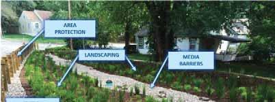
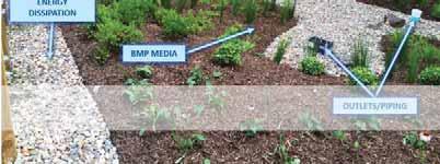
65
66
67
68
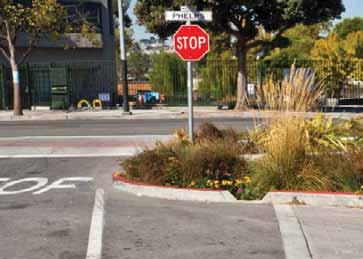
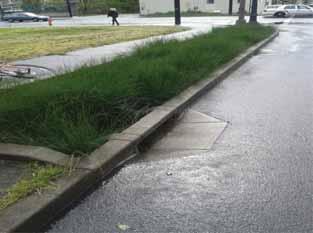
69
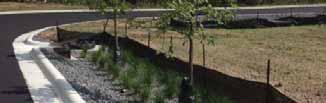

70
71
72
73 Bevel Edges of Curb to MIN 1/4" R Curb Cut Specify Width (See Note 1) Standard Curb Bevel edges of curb to MIN 1/4" R Saw Cut Curb (See Note 2) Pavement (See Note 3) ELEVATION Curb Cut Angle Varies Cut Depth to At-Grade Elevation or as Specified (See Note 3) Concrete Curb (See Note 4) Specify Width (See Note 1) Specify Length (See Note 1) Pavement ELEVATION Depressed Curb Formed Finished Edge (Typ) Energy Dissipation (See Section 4.3) BMP Flow Direction Notes Pavement PLAN Curb Cut/Depressed Curb Stormwater Inlet Curb 1. A curb cut is a cut in an existing curb, and a depressed curb is a curb poured in-place with a tapered opening. Width and angle of curb cut or taper varies based on site and stormwater capture requirements. If existing curb is damaged beyond extents specified for cut, curb shall be replaced to the nearest joint. 2. Curb cuts must be saw-cut such that all edges are square and edges beveled to a min 1 4" radius. Saw-cut per City of Fort Worth STD Specification Horizontal surface must have positive slope toward BMP installation. 4. Concrete curb materials shall conform to City of Fort Worth STD Specification All exposed surfaces shall have a broom finish. 5. Depressed curb shall transition to typical curb section per City of Fort Worth STD DWG D534. TARRANT REGIONAL WATER DISTRICT REVISED: JANUARY 2018 Curb Cut / Depressed Curb DM-DC 4.1.1
74 Sidewalk Bolt and Frame per Manufacturer's Requirements (See Notes 2 and 4) Expansion joint (Typ) Concrete Trench Specify Depth Storage Aggregate-Crushed Rock (Section 4.5.3) Specify Outlet Pipe Size and Inverts (If Applicable) SECTION A-A Provide Elevations and Inverts (Typ) A Provide Trench Elevations and Inverts (Typ) Flow A Specify Trench Length Based on Pavement Extents 6" MIN Trench Drain Cover, Pattern/Grating May Vary (See Note 1) Flow Provide Trench Elevations and Inverts (Typ) Curb Pavement Flow PLAN Trench Drain Stormwater Inlet Specify Width Notes 1. Grated located in walking surface shall have openings no greater than 1/2" in one direction, and elongated openings shall be placed so that the long dimension is perpendicular to the dominant direction of travel per Texas Accessibility Standards. 2. If trench drain assembly includes metal frame and channel, install per manufacturer instructions. 3. Cross slope and longitudinal slope of trench channel bottom may vary by design. 4. Bolt down grate and frame is required. All bolts shall be flush with existing grade of the paved surface. 5. Trench drain materials, installation, and other considerations shall comply with City of Fort Worth STD Specification including compliance with AASHTO HS-20 loading. TARRANT REGIONAL WATER DISTRICT Trench Drain DM-DC 4.1.2
75 Energy Dissipation (See Section 4.3) Stormwater Entrance BMP Curb A Transition to Typical Gutter Section Specify Length (3' MIN) Front of Curb 6" (Typ) Flow Direction Flow Direction Flow Direction 18" (Typ) Gutter Apron Pavement A PLAN Existing Gutter Existing Gutter Transition to Typical Gutter Section Curb Cut/Depressed Curb (Section 4.1.1) 6" (Typ) (See Note 1) (See Note 1) Crushed Rock per City STD Specification Compacted Subgrade ELEVATION Pavement Existing Gutter 25% MAX (See Note 2) Front of Curb BMP Notes 1. Max Slope of apron parallel to the curb is 16.67% per City of Fort Worth STD DWG D Max Slope of gutter apron cross slope is 25% per City of Fort Worth STD DWG D405. Slopes will be governed by stormwater capture requirements and entrance velocities. 3. Concrete shall conform to City of Fort Worth STD Specification ' MIN 6" MIN 6" MIN SECTION A-A TARRANT REGIONAL WATER DISTRICT Gutter Apron DM-DC 4.1.3
76 3' MIN Decorative Gravel/River Rock Stone Aggregate-Crushed Rock (Section 4.5.3) 4" MIN Perforated Distribution Piping SECTION A-A A BMP INLET STRUCTURE 4" MIN Decorative Gravel/River Rock 0.5% (Typ) Backflow Prevention (Typ) (See Note 2) Stone Aggregate-Crushed Rock (Section 4.5.3) Solid Distribution Piping Perforated Distribution Piping A 4" MIN End Cap PROFILE Notes 1. Acceptable pipe materials shall be in accordance with City of Fort Worth STD Specification Distribution piping shall include a backflow prevention device such as a check valve, a flap gate, or other appropriate measure to prevent the flow of ponded water back into the inlet structure. TARRANT REGIONAL WATER DISTRICT Distribution Piping DM-DC 4.1.4
77
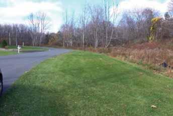
78
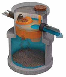
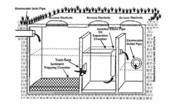
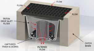
79
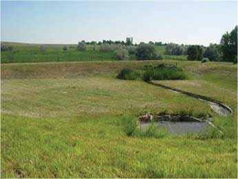
80
81
82 Pavement Ribbon Curb Distance Site Specific (See Note 1) Provide Spot Elevations (Typ) Slope Varies (See Note 3) BMP Vegetated Filter Strip Provide Spot Elevations (Typ) SECTION A-A A BMP Vegetated Filter Strip Distance Site Specific (See Note 1) Pavement PLAN A Ribbon Curb Notes 1. For optimal filtration performance, a vegetated filter strip shall have a minimum length of 15-feet in the direction of the flow unless site constraints prevent meeting this requirement. 2. The longitudinal (direction of flow) slope of a filter strip should be no less than 2% and no greater than 6%. The transverse slope should be no more than 2% and preferably 1%. 3. Filter strip shall be parallel to the adjacent pavement grade. TARRANT REGIONAL WATER DISTRICT Vegetated Filter Strip DM-DC 4.2.1
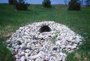
83
84
85
86 4" MIN (Typ) 2"- 3" Spacing 4" - 6" Stone Size BMP 8" MIN Concrete Bedding per City of Fort Worth STD Specification Welded Wire Mesh Placed in Bottom 1 3 of Concrete Mortar Joints BMP Compacted Subgrade SECTION A-A Rock Splash Pad Embedded in Concrete Specify Brick Material and Pattern Surface Stone Free of Jagged Edges and Tops Flush with Invert Opening 4" MIN Crushed Rock Per City of Fort Worth STD Specification " MIN Concrete Bedding per City of Fort Worth STD Specification Mortar Bed 1/2" Thick Welded Wire Mesh Placed in Bottom 1 3 of Concrete Compacted Subgrade SECTION A-A Brick Splash Pad Embedded in Concrete Specify Width (See Note 1) 4" MIN Crushed Rock Per City of Fort Worth STD Specification "x2.5"x8" Full Brick, Stand on End (Typ) 4"x2.5"x4" Half Brick, Stand on End (Typ) Specify Surface Material (See Note 2) Specify Length (See Note 1) A A BMP Curb Flow Direction Notes Stormwater Inlet (Section 4.1) Pavement PLAN 1. Dimensions of splash pad are dependent on inlet size and type, and the velocity of stormwater entering the BMP. Width of splash pad shall be greater than total stormwater entrance width and consider potential for erosion adjacent to splash pad. 2. Surface material shall be clean washed aggregate or clay bricks. Splash pad not embedded in concrete must use aggregate with a minimum 2" diameter surrounded with permanent edging, such as anchored angle iron or concrete, to prevent material from migrating into the BMP. Loose surface material shall require a permeable geotextile (Section 4.6.3) to separate the energy dissipation aggregate and underlying BMP media. 3. A minimum 3" of freeboard is required between the top of energy dissipation material and the inlet grade elevation to account for sediment accumulation. TARRANT REGIONAL WATER DISTRICT Splash Pad DM-DC 4.3.1
87 Curb Stormwater Entrance Pavement Thickness to be Determined by Engineer MIN 3" Depth (See Notes 1 & 2) BMP 6" Concrete 2" Opening SECTION A-A Welded Wire Mesh Placed in Bottom 1 3 of Concrete 4" (MIN) 2" Opening 6" Concrete 4" (MIN) SECTION B-B Full Height Curb A Stormwater Entrance Curb Cut/Depressed Curb (Section 4.1.1) Pavement Flow Direction Specify Length (See Note 1) B B BMP A Specify Width (See Note 1) 4" (MIN) PLAN Notes 1. Dimensions of sump are dependent on inlet size and type, and the velocity of stormwater entering the BMP. 2. A minimum of 3" of freeboard is required between the top of energy dissipation sump and inlet to account for sediment accumulation. 3. Steel reinforcement shall be determined by the engineer. TARRANT REGIONAL WATER DISTRICT Energy Dissipation Sump DM-DC 4.3.2
88


89
90
91 Curb Per City of Fort Worth STD DWG D534 (See Note 3) Adjacent Sidewal Front Face (See Note 5) BMP 12" MA Specify Depth Designer to Specify Depth Specify Slope Compacted Subgrade to 0Density Specify Depth SECTION Straight Curb Street Curb Per City of Fort Worth STD DWG D534 Front Face 1 2 " R 3 4 " per ft 3" R 3" R 12" MA Specify Depth BMP Specify Slope Specify Depth Bars Compacted Subgrade SECTION Curb Gutter Subgrade Per City of Fort Worth STD Specifications Notes Curbing shall conform to City of Fort Worth STD DWG D534 - Standard Curb and Gutter. Combination curb and gutter is preferred for curbing on existing curb and gutter street sections. Straight baccurb per may be used where curb is proposed for existing non-curb and gutter street sections, permeable pavement applications, and for sidewabutting the BMP. Curb heights exceeding on the front face shall be considered a curb with retaining wall and shall conform to City of Fort Worth STD DWG D534. Concrete curb materials shall conform to City of Fort Worth STD Specification All exposed surfaces shall have a brushed finish. Ribbon curb may be used to facilitate overland sheet flow to BMP where applicable. Ribbon curb shall have the same design as the standard curb, with the exception that the top of curb elevation shall be flush with the surrounding grade. TARRANT REGIONAL WATER DISTRICT Curbing DM-DC 4.4.1
92 Specify High Intensity Reflective Sheeting Size and Shape Specify Bollard Material and Pattern 40" MIN Specify Width (See Note 1) Concrete Curb or Edging Specify Slope Pavement Specify Depth 24" MIN BMP Notes Post Embedment and Footing (See Note 3) Footing shall extend to bottom of BMP section to subgrade or aggregate bedding layer for sufficient stability 1. When BMP is applied adjacent to on street parking zones, a minimum 2' clearance for vehicular door openings will be required between the back of curb or edge of pavement and the edge of the BMP. Bollards applied at intersections must not obstruct the minimum sight triangles per City of Fort Worth Public Work's Traffic Engineering Design Standards and Policy Guidelines. 2. Bollard design shall conform to manufacturer specifications and requirements. Product manufacturer or equal shall be specified on the detail. 3. Bollard post embedment shall be site specific. Footing may be embedded directly in BMP planting media or within adjacent sidewalk area. Bollards that require embedment for additional or traffic rated stability shall be designed by an engineer licensed in the State of Texas. 4. Bollards located within sidewalk area shall maintain a minimum 3' clear zone in the pedestrian pathway per ADA requirements. See City of Fort Worth STD DWG D546 for minimum sidewalk widths. 5. For Bollards located in BMPs without curb, local DOT standards shall be used to determine placement of bollard. TARRANT REGIONAL WATER DISTRICT Bollard DM-DC 4.4.2

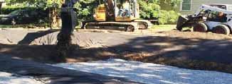
93
94
95 o o o
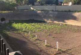


96

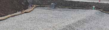

97
98
99
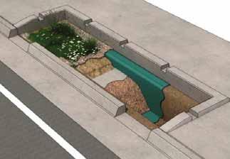
100
101


102
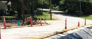
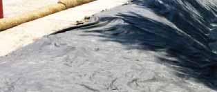
103
104
105
106
107
108
109
110
111
112
113
114
115
116
117
118
119
120
121
122
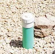
123
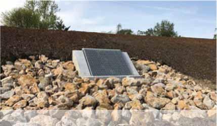
124
125
126
127 Cleanout (Section 4.8.2) Upstream End of Underdrain Shall Terminate With Two 45-Degree Bends and Riser Typical BMP Installation Connect Underdrain to Storm Sewer or Other Free-flowing Outlet Valve Box/Access Structure Anti-seep Collar (Section 4.8.6) (See Note 4) 6" MIN MIN Slope 0.5% Media Barrier (Section 4.6) Storage Aggregate-Crushed Rock (Section 4.5.3) 200' (MAX) Spacing Between Cleanouts Cleanout (Section 4.8.2) PROFILE 4" (MIN) Outflow Control Device (See Note 3) Solid PVC or HDPE Pipe Typical BMP Installation Anti-seep Collar (Section 4.8.6) (See Note 4) 12" MIN From OD of Pipe Notes 6" (MIN) Perforated Pipe (See Note 1) PLAN Outflow Control Device (See Note 3) Connect Underdrain to Storm Sewer or Open Channel Through Unperforated HDPE or PVC Pipe 1. Acceptable pipe materials shall be in accordance with City of Fort Worth STD Specification Lateral or parallel underdrains may be installed if necessary depending on size and slope of BMP. Intersecting underdrains shall be installed such that flow enters the pipe in the downstream direction. 3. A flow control mechanism such as a valve, orifice, or upturned elbow is highly recommended to be installed on the downstream end of underdrains to control discharge from the BMP. 4. Anti-seep collar should be completely free of bedding. TARRANT REGIONAL WATER DISTRICT Underdrain DM-DC 4.8.1
128 Cleanout Shall Extend Above Grade Within Vegetated BMPs (See Note 1) PVC Cleanout Lid 6" 6" MIN Solid PVC or HDPE (See Note 2) Notes CLEANOUT IN SOIL Crushed Rock Per City of Fort Worth STD Specification Cast Iron Box and Lid Bass & Hays Detail #340-1 "Stormwater" or Approved Equal (See Note 1) 1. Cleanouts in vegetated BMPs shall extend a minimum 6" above finished grade. Cleanouts in paved areas shall be flush with adjacent grade. Cleanout cast iron box & lid required in paved areas used for traffic purposes and shall be flush with the paved surface. 2. Acceptable pipe material shall be in accordance with City of Fort Worth STD Specification Cleanouts shall be required at the upstream and downstream ends of an underdrain or distribution pipe system with a maximum spacing distance of 200 feet between cleanouts. 6" 45 Degree Bend Concrete Footer for Cast Iron Box Per Manufacturer's Specifications 6" MIN Solid PVC or HDPE Riser (See Note 2) 45 Degree Wye Fitting Underdrain (Section 4.8.1) or Distribution Pipe (Section 4.1.4) Flow Direction CLEANOUT IN PAVED SURFACE TARRANT REGIONAL WATER DISTRICT Cleanout DM-DC 4.8.2
129 Nyoplast Dome Grate (Specify Diameter) or Approved Equal, (See Note 1) Overflow Elevation Above Top of BMP to be Specified, (See Note 3) Concrete Surround Specify Depth (See Note 3) Typical BMP Installation (See Notes 4 & 5) 6" Crushed Rock Per City of Fort Worth STD Specification HDPE or PVC Specify Diameter (See Note 2) Storage Aggregate-Crushed Rock (Section 4.5.3) Connect to Storm Sewer or Other Free-Flowing Outlet SECTION Notes 1. Nyoplast Drain Basin or equal is an acceptable alternative to standpipe overflow. Bedding and anchoring details shall be per manufacturer requirements. 2. Riser piping shall be made of soil tight seals and fittings and conform to City of Fort Worth STD Specification Overflow elevations shall be set at or above design ponding height such that overflow occurs only as necessary to prevent flooding of BMP facility and surrounding area. 4. Vegetation placed in the vicinity of the outlet shall maintain a minimum distance of 12-inches to prevent plant debris from clogging the structure. 5. Surface of the BMP shall be graded for positive drainage towards the outlet. TARRANT REGIONAL WATER DISTRICT Outflow Riser DM-DC 4.8.3
130 Beehive Grate ALTERNATIVE BEEHIVE GRATE OPTION Grate Multi-Stage Outlet Orifice (Optional) (Note 2). Typical BMP Installation Solid BMP Maintenance Drain Pipe Storage Aggregate- Crushed Rock (Section 4.5.3) Connect to Storm Sewer or Other Free-Flowing Outlet Perforated Underdrain (Section 4.8.1) (Where Applicable) Notes 1. BMP Drain to be used for watering BMP during maintenance activities. 2. Use of multi-stage orifice to be determined by engineer. SECTION Install Mechanical Plug/Valve Gate When Drain is Not in Service TARRANT REGIONAL WATER DISTRICT Multi-Stage Outlet Structure DM-DC 4.8.4
131 Cast Iron Box and Lid Bass & Hays Detail #340-1 "Stormwater" or Approved Equal (See Note 2) PVC Cap Concrete Surround 1'-6" BMP Installation Crushed Rock Per City of Fort Worth STD Specification HDPE or PVC Pipe (4" MIN) (See Note 4) 6" 6" 6" MIN Above Slotted Pipe Specify Depth Storage Aggregate-Crushed Rock (Section 4.5.3) 6" Solid PVC 4" PVC SCH 40 Slotted Well Screen With 0.01" Slot size (See Note 4) 4" MIN Bottom Plug SECTION Notes 1. If the observation well is located within a parking area, then it shall be flush with the paved surface. Not recommended to place observation wells in areas with high vehicular traffic due to safety concerns. 2. Well covers shall be secured in concrete surround if not secured in pavement surface restoration. Well covers in pavement shall be flush with finished grade. 3. Area surrounding well shall be restored in kind with the adjoining area. Any geotextile filter fabric penetrated during installation shall be cut and wrapped to a height of 6" upward along the solid well section. 4. Larger piping material may be required to accommodate need for monitoring or data recording equipment. TARRANT REGIONAL WATER DISTRICT Observation Well DM-DC 4.8.5
132 Concrete Collar Piping (Section 4.8) or Utility Service Align Collar With Edge of BMP Installation See Note 4 W W (See Note 2) Concrete Reinforcement Per City of Fort Worth STD DWG D416 6" MIN. ELEVATION SECTION Notes 1. Anti-seep collars used in conjunction with Utility Sleeves (Section 4.8.7) shall be installed on the upstream and downstream end of the piping at each edge of the BMP facility. Anti-seep collars and Utility sleeves shall also be installed on all utility piping joints, bends, and splices that are within the BMP. 2. 'W' shall be 3' for pipes 12" and smaller. 3. Collar shall be constructed of 4000 psi compressive strength concrete or other material providing watertight connection compatible to pipe, as approved by a PE and reviewed by the TRWD. 4. Geomembrane Liner (Section 4.6.4) shall be used where anti-seep collars are required on vertical sides of the BMP. Liners shall be minimally cut to allow for the collar and sealed with the external sheets of the anti-seep collar. 5. All fittings and seals to be installed and tested to a water-tight seal per manufacturer specifications. 6. Hydrophilic water stops may be an allowable substitute for anti-seep collars for situations where the utility or other piping passes through a concrete structure. TARRANT REGIONAL WATER DISTRICT Anti-Seep Collar DM-DC 4.8.6
133 Specify Length (See Note1) Anti-Seep Collar (Section 4.8.6) Utility Service Line Specify Diameter of Pipe Sleeve Dependent on Service Line Size Non-shrink grout or watertight sealant (See Note 2) Utility Sleeve (See Note 1) Anti-seep Collar (Section 4.8.6) (See Note 2) PROFILE Notes 1. Length of required utility sleeve dependent on type of utility service and location within or adjacent to the BMP. 2. Seal surface of utility, utility sleeve and anti-seep collar (if necessary) with non-shrink grout or other sealant. 3. Anti-seep collars (Section 4.8.6) used in conjunction with utility sleeves shall be installed on the upstream and downstream end of the piping at each edge of the BMP facility. Anti-seep collars and Utility sleeves shall also be installed on all utility piping joints, bends, and splices that are within the BMP. TARRANT REGIONAL WATER DISTRICT Utility Sleeve DM-DC 4.8.7
134
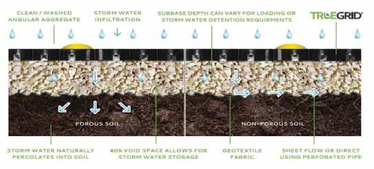
135
136
137 Soldier Course Installed at Curb (4"x 8"x 3 1 8" unless otherwise specified) Joint Material (See Note 3) Permeable Pavers (See Note 1) Specify Joint Spacing Per Manufacturer (See Note 3) Specify Thickness (See Note 2) Curbing (Section 4.4.1) SECTION Sand (Section 4.6.1) or No. 8, 89 or 9 Aggregate (See Note 3) Storage Aggregate-Crushed Rock (Section 4.5.3) 1" Notes 1. Permeable Paver material shall be either brick paver per City of Fort Worth STD Specification or permeable interlocking concrete paver per ASTM C936. All pavers shall be laid in an interlocking pattern for increased stability. Attention shall be paid to joint material to ensure uniform spacing is achieved for application that do not use interlocking pavers. 2. Thickness of brick paver shall be a minimum of 2.25" unless specified per City of Fort Worth STD Specification Thickness of a permeable interlocking concrete paver shall be dependent on usage (minimum of 2.75" for vehicular use and 2.25" for pedestrian use). 3. Joint material shall either be sand per Section or No. 8, 89, or 9 per ASTM C33. For interlocking concrete paver systems, open joints with no jointing material may be acceptable per manufacturer requirements. Open joints shall not exceed 1/2" openings per Texas Accessibility Standards. 4. Pavers shall have chamfered edges. 5. See Section 3 for full pavement section requirements for permeable pavers. TARRANT REGIONAL WATER DISTRICT Permeable Pavers DM-DC 4.9.1
138

139 TRWD WATER QUALITY MANUAL PLANNING AND IMPLEMENTING STORMWATER QUALITY PRACTICES SECTION 5 Water Quality Requirements Specific to Zone 1 (Panther Island) 5.1 INTRODUCTION AND BACKGROUND To cost-effectively meet water quality goals from stormwater runoff originating from Panther Island, TRWD is requiring revised procedures for selecting and implementing water quality practices in Zone 1 (maps of which are included in Appendix F). The Panther Island form-based code implemented by the City of Fort Worth is designed to provide for high-density, mixed use developments. While the practices and procedures for Zones outside of Panther Island could be applied in Zone 1, it would be much costlier to property owners and also place more restrictions on how an owner/operator/developer of a property could use their available footprint to achieve the needed water quality goals while meeting other requirements expressed by the form-based code as each developer would be trying to individually place and maintain stormwater quality practices on their property. The water quality requirements for Zone 1 are designed to achieve the same results in pollutant removal as they would from Zone 2. However, by constraining the number of available water quality practices that can be used in Zone 1 and placing them predominantly in the public right-ofway instead. This results in several benefits to TRWD, TRVA, and owner/operator/developers of properties: 1) It improves consistency with the Panther Island Form-Based Code (which is designed inpart to maintain look and feel compatibility among the many properties that will be built on the Island). 2) It removes most of the responsibility for operating and maintaining any stormwater quality treatment system from the owner/operator of the property and shifts it to Public Improvement District (PID) planned for Panther Island. 3) Because the number of available practices is constrained for Zone 1, this greatly increases the efficiency of stormwater quality management, substantially lowers the aggregate footprint (square footage) needed for stormwater treatment, and substantially reduces the cost of stormwater treatment for developers. 5.2 REQUIREMENTS SPECIFIC TO ZONE 1 TRWD s requirements for Zone 1 (Panther Island) in many ways simplify the implementation of this manual. The following are the specific requirements and restrictions for Zone 1: 5-1
140 TRWD Water Quality Manual June ) The vast majority of stormwater treatment will be operated and maintained by the aforementioned PID (those treatment practices within a public right-of-way); 2) Placement and type of practice required will be reviewed and approved by TRWD for Zone 1 in accordance with this manual. Placement and type of practice may be adjusted accordingly based on additional evaluation by TRWD and reflected in subsequent versions of this manual. Therefore, those working to comply with this manual are encouraged to make sure they are working with the most recent version of the manual. 3) Currently, only bioretention basins (sections and ) and permeable surfaces in the form of pervious pavers (Section 3.9) may be used in public right-of-way locations approved by TRWD. Predominantly these will be distributive bioretention basins (Section ). 4) Because of groundwater conditions on the island, all practices must have underdrains to collect and convey treated stormwater to stormwater drainage infrastructure. 5) Because of groundwater conditions on the island, it is critical that all practices, especially bioretention, have positive-side waterproofing consistent ASTM Standards (see references). Because groundwater is shallow, the significant incursion of groundwater into biorientation facilities may cause plants to die from excess water around root systems. 6) Additional treatment of stormwater may be required by TRWD for installation, operation, and maintenance by property owner/operators where the risk of pollutant discharge is increased such as in any directly-connected impervious surface (an example would be parking-garage rooftops with drainage directly to the Panther Island waterway or canals and no treatment between the two). 7) Larger detention practices (serving a larger number of properties) may be prescribed by TRWD and implementation of any larger practices for stormwater treatment is at TRWD s sole discretion in coordination with TRVA and its implementation of the Panther Island form-based code. Figure 5.1 shows the current distribution of stormwater practices in the public right-of-way by practice-type and is subject to revision by TRWD. 5.3 REFERENCES The following references are useful in specifying either elastomeric sheet waterproofing or hot fluid-applied, rubberized asphalt waterproofing (two of the more common techniques used to prevent groundwater intrusion). Other references will be needed for design purposes. ASTM International. ASTM C 1305: Test Method for Crack Bridging Ability of Liquid-Applied Waterproofing Membrane. West Conshohocken, PA: ASTM, ASTM D 5329: Test Methods for Sealants and Fillers, Hot-Applied, for Joints and Cracks in Asphaltic and Portland Cement Concrete Pavements ASTM D 6622: Guide for Application of Fully Adhered Hot-Applied Reinforced Waterproofing Systems (Reapproved 2009). ASTM E 96/E 96M: Test Methods for Water Vapor Transmission of Materials
141 TRWD Water Quality Manual June 2018 Sealant, Waterproofing, and Restoration Institute. Below Grade Waterproofing Manual. Kansas City, MO: SWRI, 2000, (Available at ASTM International. ASTM D 5295: Guide for Preparation of Concrete Surfaces for Adhered (Bonded) Membrane Waterproofing Systems. West Conshohocken, PA: ASTM, 2000 (Reapproved 2006). ASTM D 5898/D 5898M: Guide for Standard Details for Adhered Sheet Waterproofing (Reapproved 2013). 5-3
142 Figure 5.1: Distribution of Stormwater Quality Practices by Type for Zone 1 (Panther Island) Zone 1 Drainage Area Canal or Other Areas To Be Determined by TRWD/TRVA Right of Way Boundaries Stormwater Treatment Practices from TRWD Water Quality Manual Bioretention Basins (Section ) Pervious Pavers (Section 3.9) Potential Regional Pratice TRWD Water Quality Manual (June 2018) N MAIN ST 8TH ST N COMMERCE ST 7TH ST STREET F 6TH ST CALHOUN ST 4TH ST N THROCKMORTON ST HENDERSON ST STREET D STREET A WHITE SETTLEMENT RD STREET B Feet
143
144
145
146
147


148 Bioretention Basin Overview: Bioretention basins are commonly used Best Management Practices (BMP) due to the effectiveness for pollutant load reduction and visual appeal. There are two main types of bioretention basins outlined in this manual: centralized and distributive. Centralized bioretention basins are intended for larger drainage areas and include a sedimentation forebay. Distributive bioretention basin can be implemented for drainage areas less than 1-acre. These are often placed adjacent to impervious surfaces to capture runoff directly. Bioretention basins utilize infiltration and filtration through soils and vegetation in depressed basins or landscape areas to provide both water quantity and water quality benefits. The vegetation, microbes, and soils in bioretention basins provide additional treatment and removal of pollutants from stormwater runoff. Rendering of Bioretention with Components (TRWD Developer Manual, 2018) Benefits: Effective removal of suspended solids, heavy metals, adsorbed pollutants, nitrogen, phosphorous, and pathogens Based on soil conditions, groundwater levels, and geology, bioretention basins can be designed to provide groundwater recharge Flexible for use in urban retrofits or new development and can be used in both small and medium drainage basins Can be well integrated into landscaping and provide natural look and aesthetics Potential Constraints and Considerations: The design and construction of bioretention systems is critical to their performance Maintenance requirements may be time intensive and expensive Surface soil may require restoration or replacement if it becomes clogged (often after multiple years of operation) Plant materials and mulching require maintenance Effectiveness of BMP may be dependent upon site geology and soils, but an underdrain can be added if site soil infiltration capacity is insufficient May be subject to drainage area size limitations Design Guidance: All runoff from impervious surfaces should be directed towards BMPs. Important site parameters to be considered during design include the drainage area and the portion that is impervious, depth to the water table, permeability of soils, downstream water surface, and overall space required for the BMP. Bioretention basins can be designed using both centralized and distributed configurations, the main difference being the allowable drainage area and the inclusion of a sediment forebay. The water quality capture volume (WQV) should drain in less than 24-hours with a goal of 12-hours. The minimum components for a bioretention basin are as follows: stormwater inlet, pre- and post-treatment, energy dissipation, area protection (where necessary), BMP media, media barriers, landscaping, and outlets/piping. Refer to Section 4 of the TRWD Developer Manual for specific information on these components. Bioretention Basin with Components Labeled (CDM Smith, 2017)
149 Bioretention Basin Sizing Criteria: The calculations below are from Section 3.2 of the TRWD Developer Manual. This table contains the main calculations for sizing the BMP. Reference Section 3.2 and Appendix E for the specific design calculations and criteria. STEP 1 STEP 2 STEP 3 STEP 4 WATER QUALITY VOLUME ft3 (WQv = DA*[dt/(12in/ ft)]*43,560ft 3 /ac) Contributing Drainage Area (DA) ac Capture Depth for 12 Hour or 24 Hour Drawdown Time (dt) in SEDIMENT FOREBAY VOLUME (Vbc = 10%WQv) (if required) ft3 TOTAL AVAILABLE BIORETENTION ft 3 STORAGE VOLUME Top of ponding surface area (SAT) ft Bottom of ponding surface area (SAB) ft Ponding depth (dh) in Void ratio - Storage aggregate depth (df) in ORIFICE DIAMETER (do=2*(ao/π) 0.5 ) in Max. discharge of WQv (Qo) ft 3 /s Drain time (td) hr Orifice opening area (Ao) in 2 Orifice coefficient (c) - Average head (Havg) ft Inspection and Maintenance Requirements: Inspections help to ensure that the bioretention basin continues to operate throughout its lifespan. Regular inspection also indicates when certain maintenance practices are necessary. Like inspection, regular maintenance keeps the BMP operating smoothly and prolongs, or eliminates, the need for intensive rehabilitation such as side slope restabilization or replacing of corroded pipes. The table below outlines the regular and as-needed maintenance practices for bioretention basins. Specific information on inspection and maintenance requirements can be found in Appendix D of the TRWD Developer Manual. Regular Maintenance MAINTENANCE ACTION FREQUENCY Mow grassy areas Annually or more frequently during growing season Prune excessive vegetation/ Annually or more frequently during branches growing season Replant annuals Before corresponding growing season Clearing trash, debris, and foliage Monthly As-Needed Maintenance INSPECTION ISSUE FREQUENCY Standing water after design storm Check the inlet/outlet for clogging. Clear event and drawdown time if present. Check for excessive fines/hardpacking on the surface Foul odors or insects such as Promote insect predators and/or prevent mosquitos stagnant water Inlet/outlets clogged with debris Clear out accumulated debris. Install debris screens. Accumulated sediment/debris Dredge or remove accumulated sediment or debris to design elevations. Vacuum clogged permeable surfaces. Poor vegetative health / invasive Replant vegetation and remove invasive species species, taking care not to spread seeds/ spores. Excessive or overgrown vegetation Prune the excessive/overgrown vegetation. Banks/slopes eroded Repair banks/slopes such that they match design slopes. Install energy dissipaters or flow diversions. Signs of channeling or worn paths Mow or possibly regrade. Pipe corrosion Replace piping. Consider different material or covering the pipe with a corrosion resistant coating. Pollutant Removal Effectiveness: POLLUTANT REMOVAL EFFECTIVENESS* Sediment High Nutrients Moderate Trash High Metals High-Moderate Bacteria High Oil and Grease High Organics Moderate (SARA, 2013; iswm, 2014; and TCEQ, 2005) *Removal effectiveness varies dependent on infiltration capacity and design References or Future Reading: Complying with the Edwards Aquifer Rules: Technical Guidance on Best Management Practices. July TCEQ. RG-348. Accessed September < uploads/2016/04/tceq_rg-348.pdf >. iswm Technical Manual: Site Development Controls. (2014). North Central Texas Council of Governments. Accessed September < Development_Controls_ pdf >. Roach, V. (CDM Smith). March 6, Green Infrastructure Design in Your CSO Long Term Control Plan. NJ Water Environment Association: Winter Technology Transfer Seminar. New Jersey. Presentation. Accessed September San Antonio River Basin Low Impact Development Technical Design Guidance Manual. (2013). San Antonio River Authority. Accessed September < uploads/2015/05/full-lid-manual.pdf >. Tarrant Regional Water District Developer Manual. (2018). Tarrant Regional Water District (TRWD).
 requires more land than other BMPs and a constant source of influent water.")


150 Constructed Wetlands Overview: Constructed Wetlands, also referred to as stormwater wetlands, are designed to permanently hold water and increase detention time between storm events for improved treatment. This Best Management Practice (BMP) requires more land than other BMPs and a constant source of influent water. However, constructed wetlands can be an excellent option for improving water quality. Constructed wetlands employ complementary mechanisms (i.e. physical and biological) to effectively treat stormwater inflow. The slow, sinuous flow and extended detention time promotes particle settling and plant uptake. Because this BMP is not intended for infiltration, its stormwater runoff volume reduction is minimal, except through evaporation and evapotranspiration. As such, constructed wetlands are ideal at the end of a storm-to-stream sequence for final treatment before discharge into a stream. Constructed wetlands can provide site aesthetics and provide habitat for local wildlife. Benefits: Well suited for removal of particulate matter and some dissolved contaminants (TCEQ, 2005) Provides an aesthetically pleasing space for the surrounding community Provides wildlife habitat (see note below on bacterial indicator loads) Effective for large tributary areas Potential Constraints and Considerations: Requires continuous source of base flow (i.e. stormwater and dry weather inflow or make-up water inflow) Potential significant maintenance costs and large amounts of sediment removal to prevent pond stagnation, floating debris, scum, algal blooms, and unpleasant odor (TCEQ, 2005). Potential accumulation of salts and scum that can be discharged during large storm events Proper design must be used to prevent habitat for undesirable insects such as mosquitos May not be appropriate for locations with high groundwater levels due to potential for contamination Overgrowth and sediment accumulation may reduce hydraulic capacity Wildlife are a potential source of bacteria indicator loads (iswm, 2014; EPA, 2009) Design Guidance: All runoff from impervious surfaces should be directed towards the BMP. Important site considerations during design include the drainage area and the proportion of which is impervious, depth to the water table, permeability of soils, downstream water surface, and overall space required for the BMP. A long, sinuous flow path promotes pollutant removal. A micropool has been added at the outlet to improve maintenance and provide additional treatment before discharge. The water quality volume (WQV) should drain within 24 hours. The minimum components for a constructed wetland include, a stormwater inlet, pre- and post-treatment, energy dissipation, area protection, landscaping, and outlets/piping. Refer to Section 4 of the TRWD Design Manual for specific information on these components. Constructed Wetland Rendering (TRWD Design Manual, 2018)

151 Constructed Wetlands Sizing Criteria: The calculations below are from Section 3.3 of the TRWD Design Manual. This table contains the main calculations for sizing the BMP. Reference Section 3.3 and Appendix E for the specific design calculations and criteria. STEP 1 STEP 2 STEP 3 STEP 4 WATER QUALITY VOLUME ft3 Contributing Drainage Area (DA) ac Capture Depth for 24 Hour Drawdown Time (dt) in Sediment Forebay Volume ft3 (WQv = DA*[dt/(12in/ ft)]*43,560ft 3 /ac) (Vfb = 0.1in per impervious acre of drainage area) Impervious Drainage Area (Aimp) ft 2 Basin Volume (VB = VP + VS) ft3 Permanent Pool Volume (VP) = 100% WQv ft 3 WQv Surcharge Pool Volume (VS) = 120% ft 3 Orifice Diameter (do=2*(ao/π) 0.5 ) in Max. discharge of WQv (Qo) ft 3 /s Drain time (td) hr Orifice coefficient (c) - Average head (Havg) ft Orifice opening area (Ao) in 2 Inspection and Maintenance Requirements: Inspections help to ensure that the constructed wetland continues to operate throughout its lifespan. Regular inspection also indicates when certain maintenance practices are necessary. Like inspection, regular maintenance keeps the BMP running smoothly and prolongs, or eliminates, the need for intensive rehabilitation such as side slope restabilization or replacing of corroded pipes. The table below outlines the regular and as-needed maintenance practices for constructed wetlands. Specific information on inspection and maintenance requirements can be found in Appendix D of the TRWD Design Manual. Regular Maintenance MAINTENANCE ACTION FREQUENCY Clear trash, debris, weeks, and Monthly or as needed foliage Mow grassy areas Annually, but monthly during growing season Before corresponding growing season Prune excessive vegetation / Annually, but monthly during growing season branches Replant Annuals Before corresponding growing season As-Needed Maintenance INSPECTION ISSUE FREQUENCY Standing water after Check the inlet/outlet for clogging. drawdown period Foul odors or insects such as mosquitos Inlet/outlets clogged with debris Accumulated sediment/ debris higher than limit Poor vegetative health / invasive species Excessive or overgrown vegetation Retrofit BMP to prevent stagnant water Clear out accumulated debris. Install debris screens. Dredge or remove accumulated sediment or debris to design elevations. Vacuum clogged permeable surfaces. Replant vegetation and remove invasive species, taking care not to spread seeds/spores. Prune the excessive/overgrown vegetation. Banks/slopes eroded Repair banks/slopes such that they match design slopes. Install energy dissipaters or flow Signs of channeling or worn paths Broken or missing area protection Constructed Wetland (CDM Smith, 2017) diversions. Assess drainage conditions. Consider regrade. Repair or replace area protection. Pipe corrosion Replace piping. If reoccurring issue, consider different material or covering the pipe with a corrosion resistant coating. Pollutant Removal Effectiveness: POLLUTANT REMOVAL EFFECTIVENESS* Sediment High Nutrients Medium to High Trash High Metals Medium Bacteria High** Oil and Grease High Organics High** *(SARA Manual, 2013; Clary, J. 2017) ** Wetlands or other BMPs with wildlife habitat can have high internal loads of bacterial indicators, nutrients, and organics References or Future Reading: Complying with the Edwards Aquifer Rules: Technical Guidance on Best Management Practices. July TCEQ. RG-348. Accessed September < >. iswm Technical Manual: Site Development Controls. (2014). North Central Texas Council of Governments. Accessed September < >. Clary, J. et al. International Stormwater BMP Database 2016 Summary Statistics: Final Report. (2017). The Water Environment & Reuse Foundation. Accessed September < Summary%20Stats.pdf >. San Antonio River Basin Low Impact Development Technical Design Guidance Manual. (2013). San Antonio River Authority. Accessed September < >. Stormwater Wet Pond and Wetland Management Guidebook. February EPA. EPA 833-B Tarrant Regional Water District Developer Manual. (2018). Tarrant Regional Water District (TRWD).


152 Extended Dry Detention Basins Overview: Extended dry detention basins are a type of Best Management Practice (BMP) used for temporary storage of stormwater during small to moderate storm events. This BMP is designed to provide flood control by mitigating or regulating runoff while the extended storage promotes particle settling. Extended dry detention basins can be combined easily with other water quality treatment BMPs for holistic stormwater management and are meant for larger drainage areas. Unlike wet ponds and constructed wetlands, extended dry detention basins should drain completely after a storm and remain dry between storm events. Extended Dry Detention Basin, City of Lenexa, KS Benefits: Easily incorporated into a sequence of BMPs for holistic treatment of stormwater Provides temporary stormwater storage to mitigate downstream flooding Effective for larger drainage areas Can be used for recreation between storm events Relatively low cost compared to other BMPs such as wet ponds due to less excavation Requires less stringent maintenance than other BMPs which maintain permanent pools throughout the year If properly prevented, less chance of harboring pests such as mosquitoes than other BMPs with permanent pools of water Potential Constraints and Considerations: Limited effectiveness for some pollutants. Coordinate with other BMPs where possible or include pre- / post-treatment Water quality treatment is limited to small to moderate storm events Design Guidance: The first step in design is to accurately delineate the drainage area of the BMP. Next, all runoff from impervious surfaces should be directed towards the BMP. Important site considerations during design include the drainage area and the portion of which is impervious, depth to the water table, permeability of soils, downstream Extended Dry Detention Basin Plan and Profile (Columbus Stormwater Drainage Manual, 2012) Rendering of an Extended Dry Detention Basin and Components After a Storm (TRWD Developer Manual, 2018) water surface, and overall space required for the BMP. Micropools should be included at the outlet for maintenance and water quality benefits. The water quality volume (WQv) should drain within 40 to 48 hours. The minimum components for an extended dry detention basin include, a stormwater inlet, pre- and post-treatment, energy dissipation, area protection, landscaping, and outlets/piping. Refer to Section 4 of the TRWD Developer Manual for specific information on these components.
153 Extended Dry Detention Basins Sizing Criteria: The calculations below are from Section 3.6 of the TRWD Developer Manual. This table contains the main calculations for sizing the BMP. Reference Section 3.6 and Appendix E for the specific design calculations and criteria. STEP 1 STEP 2 STEP 3 STEP 4 Water Quality Capture Volume ft3 (WQv = AD*[dt/(12in/hr)] *43,560ft 3 /ac) Contributing Drainage Area (AD) ac Capture Depth for 48 Hour Drawdown Time (dt) in Sediment Forebay Volume (Vfb = 10%WQv) ft3 Basin Volume (VB = 100% WQv) ft3 Orifice Diameter (do=2*(ao/π) 0.5 ) in Max. discharge of WQv (Qo) ft 3 /s Drain time (td) hr Orifice opening area (Ao) in 2 Orifice coefficient (c) - Average head (Havg) ft Inspection and Maintenance Requirements: Inspections help to ensure that the extended dry detention basin continues to operate effectively throughout its lifespan. Regular inspection also indicates when certain maintenance practices are necessary. Like inspection, regular maintenance keeps the BMP running smoothly and prolongs, or eliminates, the need for intensive rehabilitation such as side slope restabilization or replacing of corroded pipes. The table below outlines the regular and as-needed maintenance practices for extended dry detention basins. Specific information on inspection and maintenance requirements can be found in Appendix D of the TRWD Developer Manual. Regular Maintenance MAINTENANCE ITEMS FREQUENCY Clear trash, debris, weeks, and Monthly or as needed foliage Mow lawn Annually, but monthly during growing season Replant Annuals Before corresponding growing season As-Needed Maintenance INSPECTION ISSUE FREQUENCY Standing water after drawdown Check the inlet/outlet for clogging. Check period for excessive fines/hard-packing on the surface Foul odors or insects such as mosquitos Retrofit BMP to prevent stagnant water Inlet/outlets clogged with debris Clear out accumulated debris Accumulated sediment/debris Dredge or remove accumulated sediment. higher than limit Vacuum clogged permeable surfaces. Poor vegetative health / invasive Replant vegetation and remove invasive species species. Excessive or overgrown vegetation Prune the excessive/overgrown vegetation. Banks/slopes eroded Repair banks/slopes such that they match design slopes. Install energy dissipaters or flow diversions if reoccurring issue. Signs of channeling or worn paths Mow or possibly regrade. Broken or missing area protection Repair or replace area protection. Pipe corrosion Replace piping. Consider different material or cover the pipe with a corrosion resistant coating. Pollutant Removal Effectiveness: POLLUTANT REMOVAL EFFECTIVENESS* Sediment Medium Nutrients Low to Medium Trash High Metals Medium Bacteria Medium to High Oils and Grease No Data Organics Low (iswm, 2014; TCEQ, 2005; International Stormwater BMPDatabase, 2017) *nutrient, metals, and organics removal when bound to sediments that are removed References or Future Reading: Complying with the Edwards Aquifer Rules: Technical Guidance on Best Management Practices. July TCEQ. RG-348. Accessed September < >. Extended Dry Detention Basin. Green Infrastructure. (no year pub.). City of Lenexa, Kansas. Image. Accessed September < divisions/rain_to_recreation/learn_more/green_infrastructure/ >. Facilities. Stormwater Partners. Image. Accessed January < >. iswm Technical Manual: Site Development Controls. (2014). North Central Texas Council of Governments. Accessed September < >. San Antonio River Basin Low Impact Development Technical Guidance Manual. (2013). San Antonio River Authority. 1st edition. Accessed September < >. Columbus Stormwater Drainage Manual. (2012). The City of Columbus: Division of Sewerage and Drainage. Accessed September < >. Tarrant Regional Water District Developers Manual. (2018) Tarrant Regional Water District (TRWD). BMP Database Tool: Texas BMPs. (2016). International Stormwater BMP Database. Accessed August <
 only covers the use of permeable pavers.")


154 Permeable Surfaces Overview: Permeable surfaces are a type of Best Management Practice (BMP) that treats stormwater sheet flow over what would alternatively be conventional impervious surfaces. This type of stormwater BMP consists of permeable pavers, porous concrete, porous asphalt, and grassed-modular grid systems. The TRWD Developer Manual (DM) only covers the use of permeable pavers. Permeable pavers can be used to replace or in place of impervious surfaces and to temporarily store water in the storage aggregate layer. The overall performance of permeable surfaces is variable based on design, duration of use, and frequency of maintenance. Benefits: Permeable pavers are easily adapted to site layout plan Can be effective at reducing runoff rate and volume instead of traditional impervious areas Can reduce stormwater infrastructure footprint requirements of downstream BMPs Promotes dual-purpose usage of pavement as a transportation surface and water treatment media Can be used to reduce stormwater pollutants loading to downstream surface waters Potential Constraints and Considerations: Regular maintenance required to prevent clogging of porous media by sediment, which may result in reduced pollutant removal effectiveness (SARA Manual, 2013) Permeable surfaces have potential to compress and lose permeability when installed in areas subject to heavy vehicle loads. Restricted to surfaces with minimal slopes Restricted to grades of 5% or less. 2% or less is recommended. Permeable pavers and porous concrete sidewalk (CDM Smith, 2017) Permeable pavers aggregate joints (S. Landgren, 2011) Permeable pavers and rain gardens (Harroch, W., et al., 2017) Design Guidance: The first step is accurate delineation of the drainage area of the BMP. Important site considerations during design include the drainage area and the portion of which is impervious, depth to the water table, permeability of soils, downstream water surface, and overall space required for the BMP. When delineating the drainage area and considering use of permeable pavers, the recommended ratio of treated drainage area to permeable pavers surface area is 1.5 to 1. The water quality capture volume (WQv) should drain between 12 hours to 48 hours after the storm event. The minimum components for permeable pavers are as follows: area protection, BMP media, media barriers, outlets/piping, and permeable surfaces. Refer to Section 4 of the TRWD DM for specific information on these components. Rendering of permeable pavers with components after a storm (TRWD DM, 2018)

 ft2 Orifice Diameter (do=2*(ao/π) 0.5 ) in Max.")
155 Permeable Surfaces Pervious Pavement, National Association of City Transportation Officials Sizing Criteria: The calculations below are from Section 3.8 of the TRWD Developer Manual. This table contains the main calculations for sizing the BMP. Reference Section 3.8 and Appendix E for the specific design calculations and criteria. STEP 1 STEP 2 STEP 3 Water Quality Capture Volume ft3 (WQv = DA*[dt/12 *43,560ft 3 /ac) Contributing Drainage Area (DA) ac Capture Depth for 24 Hour Drawdown Time (dt) in Required Permeable Surface Area (SAP = DA/1.5) ft2 Orifice Diameter (do=2*(ao/π) 0.5 ) in Max. discharge of WQv (Qo) ft 3 /s Drain time (td) hr Orifice opening area (Ao) in 2 Orifice coefficient (c) - Average head (Havg) ft Inspection and Maintenance Requirements: Inspections help to ensure that the permeable pavers continue to operate throughout their lifespan. Regular inspection also indicates when certain maintenance practices are necessary. Like inspection, regular maintenance keeps the BMP running smoothly and prolongs, or eliminates, the need for intensive rehabilitation such as side replacing pavers. The table below outlines the regular and as-needed maintenance practices for permeable pavers. Specific information on inspection and maintenance requirements can be found in Appendix D of the TRWD DM. Regular Maintenance MAINTENANCE ITEMS FREQUENCY Clear trash, debris, and foliage Monthly or as needed Vacuum sweeping Annually As-Needed Maintenance INSPECTION ISSUE ACTION Pooling of water over surface course 48 hours after storm event Additional vacuum sweeping when dry Significant deterioration of surface course or pavers and structural integrity of pavement, inlets/ outlets, and observation wells Possible replacement of surface course, pavers, inlets/outlets, and observation well components depending on severity Inlet/outlets clogged with debris Clear out accumulated debris. If needed and not installed previously, install debris screens. Pipe corrosion Replace piping. If reoccurring issue, consider different material or covering the pipe with a corrosion resistant coating. Pollutant Removal Effectiveness: POLLUTANT REMOVAL EFFECTIVENESS* Sediment High Nutrients Low** Trash High Metals Medium Bacteria High Oil and Grease Medium Organics Low *(SARA, 2013; International Stormwater BMP Database, 2017) ** Removal occurs when associated with retainment of nutrient- and metal-bound sediments or filtering oil/grease on underlying soil media. References or Future Reading: Harrouch, W., Roach, V., and M. Dodson (CDM Smith). October 23, Turning Ultra Urban Into Ultra Green for CSO Control in the Bronx. Main Stormwater Conference. Portland, Maine. Presentation. Accessed September iswm Technical Manual: Site Development Controls. (2014). North Central Texas Council of Governments. Accessed September < >. Landgren, S. Hartford, CT Green Capitals Project. (2011). CDM Smith. Photograph. Pervious Pavement. (no year). National Association of City Transportation Officials. Accessed September < >. Roach, V. (CDM Smith). March 6, Green Infrastructure Design in Your CSO Long Term Control Plan. NJ Water Environment Association: Winter Technology Transfer Seminar. New Jersey. Presentation. Accessed September San Antonio River Basin Low Impact Development Technical Design Guidance Manual. (2013). San Antonio River Authority. Accessed September < >. Tarrant Regional Water District Developer Manual. (2018). Tarrant Regional Water District (TRWD). Tennessee Permanent Stormwater Management and Design Guidance Manual. December Tennessee Department of Environment and Conservation. 1st ed. Accessed September < >.

.")

156 Retention & Irrigation Basin Overview: Retention/irrigation basins are a Best Management Practice (BMP) used to collect stormwater runoff with the intention of using it for irrigation of appropriate landscape areas. Unlike other BMPs such as extended dry detention basins or wet basins, retention/ irrigation basins use mechanical components such as pumps, wet wells, and an irrigation system. Retention/irrigation basins typically are used in large contributing drainage areas, but site selection must be balanced with available landscape area to irrigate. This BMP relies on the infiltration capacity of the irrigated areas to discharge the full captured water quality volume (WQv). While the sediment forebay removes the majority of the suspended solids, collected water is treated further through infiltration and plant uptake in the irrigated area. Benefits: Excellent pollutant removal through filtration of sediments, pollutant-bound sediments, oils, greases, and other organics as well as uptake of nutrients and some metals by vegetation when properly designed, constructed, and maintained Beneficial for areas that do not have much rainfall because it can reduce irrigation demand on groundwater Can provide indirect groundwater recharge through infiltration Potential Constraints and Considerations: Maintenance requirements and costs to keep the irrigation system operational are potentially high (TCEQ, 2005) Must match the amount of irrigated land to the captured stormwater volume Potential for groundwater contamination if inadequate soil coverage over irrigated areas (TCEQ, 2005; iswm, 2014) This system requires mechanical components such as pumps, irrigation system, and electrical power which adds additional cost to the BMP Retention irrigation pond (City of Austin Watershed Protection Department, TX) Retention/irrigation basin and components rendering after storm event (TRWD Developer Manual, 2018) Design Guidance: First, accurately delineate the drainage area of the BMP. Next, all runoff from impervious surfaces should be directed towards the BMP. Important site considerations during design include the drainage area and the portion of which is impervious, depth to the water table, permeability of soils, downstream water surface, and overall space required for the BMP. Retention/irrigation basins range from dry-concrete basins to vegetated basins with a permanent pool. Stored water drains to a wet well outside of the basin and is then pumped to irrigate a landscaped area. The minimum components for an extended dry detention basin include, a stormwater inlet, pre- and post-treatment, energy dissipation, area protection, landscaping, and outlets/piping. Refer to Section 4 of the TRWD Developer Manual for specific information on these components. Retention/irrigation basins also require wet wells, pumps, and an irrigation system. Retention basin, outlet, and inlet structure (Kannan, 2014)
157 Retention & Irrigation Basin Sizing Criteria: The calculations below are from Section 3.5 of the TRWD Developer Manual. This table contains the main calculations for sizing the BMP. Reference Section 3.5 and Appendix E for the specific design calculations and criteria. STEP 1 STEP 2 STEP 3 STEP 4 STEP 5 Water Quality Capture Volume ft3 (WQv = DA*[dt/(12in/hr)] *43,560ft 3 /ac) Contributing Drainage Area (DA) ac Capture Depth (dt) in Sediment Forebay Volume ft3 (Vfb = 0.1in per impervious acre of drainage area) Impervious Drainage Area (Aimp) ft 2 Retention Basin Volume ft3 (VRB = 100% WQv or 2.2WQv if includes a permanent pool) Orifice Diameter (do=2*(ao/π) 0.5 ) in Max. discharge of WQv (Qo) ft 3 /s Drain time (td) hr Orifice opening area (Ao) in 2 Orifice coefficient (c) - Average head (Havg) ft Irrigation Area (AI=[(12in/ft)WQv]/[60r]) in Soil permeability (r) in/hr Inspection and Maintenance Requirements: Inspections help to ensure that the retention/irrigation basin continues to operate throughout its lifespan. Regular inspection also indicates when certain maintenance practices are necessary. Like inspection, regular maintenance keeps the BMP running smoothly and prolongs, or eliminates, the need for intensive rehabilitation such as side slope restabilization or replacing of corroded pipes. The table below outlines the regular and as-needed maintenance practices for retention/irrigation basins. Specific information on inspection and maintenance requirements can be found in Appendix D of the TRWD Developer Manual. Regular Maintenance MAINTENANCE ITEMS FREQUENCY Clear trash, debris, weeks, and Monthly or as needed foliage Mow lawn Annually, but monthly during growing season Prune excessive vegetation / Annually, but monthly during growing season branches As-Needed Maintenance INSPECTION ISSUE ACTION Standing water after design storm Check the inlet/outlet for clogging. Clear if event and drawdown time necessary. Check for excessive fines/hardpacking on the surface. Foul odors or insects such as mosquitos Retrofit BMP to prevent stagnant water Inlet/outlets clogged with debris Clear out accumulated debris. Accumulated sediment/debris Dredge or remove accumulated sediment or higher than limit debris to design elevations. Poor vegetative health / invasive Replant vegetation and remove invasive species species. Excessive or overgrown vegetation Prune the excessive/overgrown vegetation. Banks/slopes eroded Repair banks/slopes. Install energy dissipaters or flow diversions. Signs of channeling or worn paths Mow or possibly regrade. Broken or missing area protection Repair or replace area protection. Pipe corrosion Replace piping. Consider different material or covering the pipe with a corrosion resistant coating. Pump/Irrigation Equipment Failure Replace or repair equipment. Pollutant Removal Effectiveness: POLLUTANT REMOVAL EFFECTIVENESS* Sediment High Nutrients Medium to High** Trash High Metals High Bacteria High Oil and Grease No Data Organics No Data * (iswm, 2014) ** Depends on vegetation in the retention ponds for nutrient uptake References or Future Reading: Complying with the Edwards Aquifer Rules: Technical Guidance on Best Management Practices. July TCEQ. RG-348. Accessed September < >. iswm Technical Manual: Site Development Controls. (2014). North Central Texas Council of Governments. Accessed September < >. Kannan, N., Jeong, J., Arnold, J., Gosselink, L. Hydrologic Modeling of a Retention Irrigation System. (2014). American Society of Civil Engineers: Journal of Hydrologic Engineering: 19(5). Accessed September < >. Retention Irrigation Ponds. The City of Austin: Watershed Protection Department. Image. Accessed January < >. Tarrant Regional Water District Developer Manual. (2018). Tarrant Regional Water District (TRWD).


158 Sand and Media Filters Overview: Sand and media filters are a versatile, well-established structural Best Management Practice (BMP) that provides treatment of stormwater runoff by filtration through sand or other filtration media. To improve treatment effectiveness, sand and media filters are paired with a pre-treatment BMP to remove large debris and sediment from the runoff inflow. This BMP is easily incorporated into new developments or adapted for retrofits in re-development sites. The sand and media filters are suitable for relatively large, highly impervious drainage areas. Benefits: Offer design flexibility and can be implemented in urban retrofits or new development projects Effective in the removal of suspended solids, oil and grease, heavy metals, and particle-bound nutrients and pathogens Can be used to reduce peak runoff rates for relatively frequent storms Can incorporate deeper ponding depths of up to 5-feet to limit the required footprint Potential Constraints and Considerations: Sand filters in basins with heavy sediment loads are subject to clogging and require more frequent maintenance to maintain optimal filtration rate Frequent trash removal may be required for sites with high traffic volume Can lack aesthetic appeal Stagnant water due to clogging and /or inadequate maintenance may create breeding habitat for nuisance conditions Surface Sand Filter Seneca Best Management Practice. DEP Montgomery County, MD. Example of Surface Sand Filter (Bender Wells Clark Design, SARA, 2013) Design Guidance: First, delineate the drainage area of the BMP. Next, all runoff from impervious surfaces should be directed towards the BMP. Important site considerations during design include the drainage area and the portion of which is impervious, depth to the water table, permeability of soils, downstream water surface, and overall space required for the BMP. Sand and media filters include multiple chambers: a sediment forebay or sedimentation chamber, and a filtration chamber. If the drainage area is less than 2 acres, then a vegetated filter strip or grass swale can be used in lieu of a sediment forebay. The depth of the filtration basin must be balanced with the frequency of required maintenance. The deeper the filtration basin, the more frequent the maintenance. The water quality volume (WQv) in the sand and media filter should drain in 24 hours. The minimum components for the sand and media filter is as follows: stormwater inlet, pre- and post-treatment, energy dissipation, area protection, BMP media, media barriers, landscaping, and outlets/piping. Refer to Section 4 of the TRWD Developer Manual for specific information on these components. Sand Filter Rendering and Components (TRWD Developer Manual, 2018)
159 Sand And Media Filters Sizing Criteria: The calculations below are from Section 3.1 of the TRWD Developer Manual. This table contains the main calculations for sizing the BMP. Reference Section 3.1 and Appendix E for the specific design calculations and criteria. STEP 1 STEP 2 STEP 3 STEP 4 STEP 5 STEP 6 Water Quality Capture Volume ft3 (WQv = DA*[dt/12* 43,560ft3/ac) Contributing Drainage Area (DA) ac Capture Depth for 24 Hour Drawdown Time (dt) in Sediment Forebay Volume (Vfb = 25%WQv) ft3 Surface Area of ft 3 Filtration Chamber (Af = WQv/[kTf] where k=3.5ft/day) Filtration chamber drain time (Tf) days Total Available Sand Filter ft 3 Water Quality Storage Volume Surface area top of basin ponding storage (SAT) ft2 Surface area bottom of basin ponding storage (SAB) ft2 Depth of ponding (Hf) ft Depth of storage aggregate (Hagg) ft Void ratio - Sand Filter Chamber Total Depth (Ht = [Hf/(12in/ft)]+Hm) ft Filter media depth (Hf) in Filtration chamber depth (Hm) ft Orifice Diameter (do=2*(ao/π) 0.5 ) in Max. discharge of WQv (Qo) ft 3 /s Drain time (td) hr Orifice opening area (Ao) in 2 Orifice coefficient (c) - Average head (Havg) ft Inspection and Maintenance Requirements: Inspections help to ensure that the sand and media filters throughout their lifespan. Regular inspection also indicates when certain maintenance practices are necessary. Like inspection, regular maintenance keeps the BMP running smoothly and prolongs, or eliminates, the need for intensive rehabilitation such as media replacement. The table below outlines the regular and as-needed maintenance practices for sand and media filters. Specific information on inspection and maintenance requirements can be found in Appendix D of the TRWD Developer Manual. Regular Maintenance MAINTENANCE ITEMS FREQUENCY Clearing trash, debris, and foliage Monthly or as needed As-Needed Maintenance INSPECTION ISSUE ACTION Standing water after drawdown Check the inlet/outlet for clogging. Clear if time necessary. Foul odors or insects such as mosquitos Retrofit BMP to prevent stagnant water Inlet/outlets clogged with debris Clear out accumulated debris. Accumulated sediment/debris Dredge or remove accumulated sediment or debris. Surface media spent Replace the top of the surface media Broken or missing area protection Repair or replace area protection. Pipe corrosion Replace piping. If reoccurring issue, consider different material or covering the pipe with a corrosion resistant coating. Pollutant Removal Effectiveness: POLLUTANT REMOVAL EFFECTIVENESS* Sediment High Nutrients Trash High Metals Medium to High Bacteria Medium to High Oil and Grease High Organics Medium to High (SARA, 2013; iswm, 2014; and TCEQ, 2005) * removal effectiveness varies dependent on infiltration capacity and design ** Sources have ranged from low removal to high removal References or Future Reading: Complying with the Edwards Aquifer Rules: Technical Guidance on Best Management Practices. July TCEQ. RG-348. Accessed September < uploads/2016/04/tceq_rg-348.pdf >. iswm Technical Manual: Site Development Controls. (2014). North Central Texas Council of Governments. Accessed September < Development_Controls_ pdf >. San Antonio River Basin Low Impact Development Technical Design Guidance Manual. (2013). San Antonio River Authority. Accessed September < uploads/2015/05/full-lid-manual.pdf >. Tarrant Regional Water District Developer Manual. (2018). Tarrant Regional Water District (TRWD). Young, G.K., et al Evaluation and Management of Highway Runoff Water Quality. U.S. Department of Transportation. Federal Highway Administration: Office of Environment and Planning. Publication No. FHWA-PD


160 Vegetated Filter Strips and Grass Swales Overview: Vegetated Filter Strips (VFS) and Grass Swales can be used to treat stormwater runoff from low density impervious areas or along linear impervious surfaces, such as roadways or sidewalks. VFS are linear strips of natural, grass vegetation extended over a gentle slope which use the biological and physical properties of the vegetation and infiltration to remove sediment and other pollutants in sheet flow runoff. Grass swales are grass-lined ditches that can be used to convey and treat shallow concentrated flow. These Best Management Practices (BMPs) should not be used as a stand-alone BMP for developments and can be used as pre- or post-treatment along with other water quality BMPs. Benefits: VFS and grass swales are relatively simple and low cost to design and construct Both can be used for pretreatment and reduction of sediment from stormwater Both have simple, aesthetically pleasing qualities and provide landscaping opportunities Low maintenance requirements VFS and grass swales are effective along linear, narrow, impervious surfaces and are easily distributed around a site Potential Constraints and Considerations: May not be suitable for industrial sites or large drainage areas, unless used to convey sub-areas as replacement for storm sewers VFS requires sheet flow across vegetated areas Require mild slopes to allow vegetation to provide filtration and to maintain low velocities Application in arid areas is limited because of the need for dense vegetation Does not provide sufficient attenuation of peak flows, unless check dams or other storage mechanisms are installed to the grass swale Design Guidance: First, delineate the drainage area of the BMP. Next, all runoff from impervious surfaces should be directed towards the BMP(s). Important site Grass Swale (Niskayuna Business Park-DEC, NY, 2005) considerations during design include assessment of the impervious portion of the drainage area, depth to the water table, permeability of soils, downstream water surface, and overall space required for the BMP. VFS typically have one gentle side slope where the sheet flow runoff is treated. Grass swales are more channelized, having shallow side slopes on both sides of the channel perpendicular to the longitudinal flow path. VFS and grass swales can be enhanced by constructing check dams along the flow path to store and treat the stormwater for an extended period. Water should not pool in these BMPs. If check dams are installed, then the ponding behind the dams must drain within 48 hours. The minimum components for VFS and grass swales are as follows: stormwater inlet, pre- and post-treatment, energy dissipation, area protection, BMP media, media barriers, landscaping, and outlets/piping. Refer to Section 4 of the TRWD Developer Manual for specific information on these components. Grass Swale (Dominican College-DEC, NY, 2007) Vegetated Grass Swale (Dott Architecture, 2010)
161 Vegetated Filter Strips And Grass Swales Sizing Criteria: The criteria below are from Section 3.7 of the TRWD Developer Manual. This table contains the main calculations for sizing the BMP. Reference Section 3.7 and Appendix E for the specific design calculations and criteria. STEP 1 STEP 2 STEP 3 STEP 4 STEP 5 WATER QUALITY CAPTURE VOLUME Grass Swale: Contributing Drainage Area (DA) less than 5ac? VFS: Length of contributing drainage area in direction of flow less than 75-feet? UPSTREAM OR DOWNSTREAM BMP? IF NOT, JUSTIFICATION? INFLOW PARAMETERS Grass Swale: Less than 4 inches of sheet flow? Grass Swale: Energy dissipation at the inlet to reduce channelized water velocities to < 1-ft/s? VFS: Less than 2 inches of sheet flow? VFS OR GRASS SWALE PARAMETERS Grass swales: Longitudinal slope less than 4% with max. water velocity less than 1-ft/s? Grass swale: Side slopes no steeper than 3:1 (horizontal:vertical) and channel bottom between 2-feet and 6-feet? VFS: Flow path at least 15-feet with 2% to 6% longitudinal slope and transverse slope less than 2%? VFS: Minimum of 12-inches of soil cover and dense vegetative cover? CHECK DAM PARAMETERS Does it drain within 48-hours? Dam has max. height of 12-inches with 3:1 side slopes? Inspection and Maintenance Requirements: Inspections help to ensure that the VFS and the grass swales continue to operate at their designed throughout lifespan. Regular inspection also indicates when certain maintenance practices are necessary. VFS and grass swales require less maintenance than other BMPs, but consistent inspection and maintenance keeps the BMP running smoothly and prolongs, or eliminates, the need for intensive rehabilitation such as side slope restabilization. The table below outlines the regular and asneeded maintenance practices for VFS and grass swales. Specific information on inspection and maintenance requirements can be found in Appendix D of the TRWD Developer Manual. Regular Maintenance MAINTENANCE ITEMS FREQUENCY Clear trash, debris, weeds, and Monthly or as needed foliage Mow lawn Annually, but monthly during growing season As-Needed Maintenance INSPECTION ISSUE ACTION Standing water after drawdown Check for excessive fines/hard-packing on time the surface Foul odors or insects such as mosquitos Retrofit BMP to prevent stagnant water Inlet/outlets clogged with debris Clear out accumulated debris. Accumulated sediment/debris Dredge or remove accumulated sediment higher than limit or debris. Poor vegetative health / invasive Replant vegetation and remove invasive species species. Excessive or overgrown vegetation Prune the excessive/overgrown vegetation. Banks/slopes eroded Repair banks/slopes such that they match design slopes. Install energy dissipaters or flow diversions. Signs of channeling or worn paths Mow or possibly regrade. Pipe corrosion Replace piping. If reoccurring issue, consider different material or covering the pipe with a corrosion resistant coating. Pollutant Removal Effectiveness: POLLUTANT REMOVAL EFFECTIVENESS Sediment Medium to High Nutrients Low to Medium Trash Metal Low to Medium Bacteria * Oil and Grease Organics (SARA, 2013; iswm, 2014) * Removal effectiveness will vary based on removal mechanism (i.e. adsorption to sediment or vegetation or infiltration) References or Future Reading: Dominican College Dry Swale. (2007). New York State Department of Environmental Conservation. Accessed September < >. iswm Technical Manual: Site Development Controls. (2014). North Central Texas Council of Governments. Accessed September < Development_Controls_ pdf >. Niskayuna Busiess Park Dry Swale. (2005). New York State Department of Environmental Conservation. Accessed September < >. San Antonio River Basin Low Impact Development Technical Design Guidance Manual. (2013). San Antonio River Authority. Accessed September < uploads/2015/05/full-lid-manual.pdf >. Sustainable practices for landscape design: vegetated swales. (2010). Dott Architecture. Accessed September < >. Tarrant Regional Water District Developer Manual. (2018). Tarrant Regional Water District (TRWD).


 Benefits: Well suited for removal of particulate matter and some dissolved contaminants (TCEQ, 2005) Provides an aesthetically pleasing space for")

162 Wet Basins Overview: Wet basins are a Best Management Practice (BMP) designed to retain stormwater between runoff events to allow the retained volume to be treated for an extended period. These BMPs are also known as wet ponds, stormwater ponds, or retention ponds. They are similar to extended dry detention basins, but this BMP maintains a permanent pool throughout the year. Wet basins remove pollutants from the surcharge primarily through particle settling and plant uptake of nutrients. This BMP is not intended for infiltration. Therefore, the stormwater runoff volume reduction is minimal, except through evaporation and evapotranspiration. Wet basins require large amounts of space and contributing drainage area. A source of inflow is needed to maintain a permanent pool throughout the year. Wet basin (Tennessee Permanent SW Mgmt and DGM, 2014) Benefits: Well suited for removal of particulate matter and some dissolved contaminants (TCEQ, 2005) Provides an aesthetically pleasing space for the surrounding community Provides wildlife habitat. See note below on bacterial indicator loads Effective for large tributary areas Potential Constraints and Considerations: Requires continuous source of base flow (i.e. stormwater inflow or make-up water inflow) Potential significant maintenance costs and large amounts of sediment removal to prevent pond stagnation, floating debris, scum, algal blooms, and unpleasant odor (TCEQ, 2005). Potential accumulation of salts and scum that can be discharged during large storm events Wet basin (CDM Smith, 2017) Proper design must be used to prevent habitat for undesirable insects such as mosquitos May not be appropriate for locations with high groundwater levels due to potential for contamination Overgrowth and sediment accumulation may reduce hydraulic capacity Design Guidance: First, delineate the drainage area of the BMP. Next, all runoff from impervious surfaces should be directed towards the BMP. Important site considerations during design include assessment of the portion of which is impervious, depth to Wet basin multi-stage outlet (SARA Manual, 2013) the water table, permeability of soils, downstream water surface, and overall space required for the BMP. The wet basin does not vary in depth as much as the constructed wetland, though, 15% of the total surface area of the basin must be made up of a littoral zone, or safety bench. Like the constructed wetland, it has a micropool at the outlet for additional treatment before discharge. The water quality volume (WQv) should drain within 12 hours. The minimum components for a wet basin include, a stormwater inlet, pre- and post-treatment, energy dissipation, area protection, landscaping, and outlets/piping. Refer to Section 4 of the TRWD DM for specific information on these components. Rendering of a wet basin after a storm (TRWD DM, 2018)
163 Wet Basins Sizing Criteria: The calculations below are from Section 3.4 of the TRWD DM. This table contains the main calculations for sizing the BMP. Reference Section 3.4 and Appendix E for the specific design calculations and criteria. STEP 1 STEP 2 STEP 3 STEP 4 Water Quality Capture Volume ft3 (WQv = DA*[dt/(12in/hr)] *43,560ft 3 /ac) Contributing Drainage Area (DA) ac Capture Depth for 12 Hour Drawdown Time (dt) in Sediment Forebay Volume ft3 (Vfb = 0.1in per impervious acre of drainage area) Impervious Drainage Area (Aimp) ft 2 Basin Volume (VB = VP + VS) ft3 Permanent Pool Volume (VP) = 100% WQv ft 3 WQv Surcharge Pool Volume (VS) = 120% ft 3 Orifice Diameter in (do=2*(ao/π) 0.5 ) Max. discharge of WQv (Qo) ft 3 /s Drain time (td) hr Orifice opening area (Ao) in 2 Orifice coefficient (c) - Average head (Havg) ft Inspection and Maintenance Requirements: Inspections help to ensure that the wet basin continues to operate a throughout its lifespan. Regular inspection also indicates when certain maintenance practices are necessary. Like inspection, regular maintenance keeps the BMP running smoothly and prolongs, or eliminates, the need for intensive rehabilitation such as side slope restabilization or replacing of corroded pipes. The table below outlines the regular and as-needed maintenance practices for wet basins. Specific information on inspection and maintenance requirements can be found in Appendix D of the TRWD DM. Regular Maintenance MAINTENANCE ITEMS FREQUENCY Clear trash, debris, weeks, and Monthly or as needed foliage Mow lawn Annually, but monthly during growing season Prune excessive vegetation / Annually, but monthly during growing season branches Replant Annuals Before corresponding growing season As-Needed Maintenance INSPECTION ISSUE ACTION Standing water after design storm Check the inlet/outlet for clogging. Clean if event and drawdown time necessary. Foul odors or insects such as mosquitos Retrofit BMP to prevent stagnant water Inlet/outlets clogged with debris Clear out accumulated debris. Accumulated sediment/debris Dredge or remove accumulated sediment higher than limit or debris to design elevations. Vacuum clogged permeable surfaces. Poor vegetative health / invasive Replant vegetation and remove invasive species species, taking care not to spread seeds/ spores. Excessive or overgrown vegetation Prune the excessive/overgrown vegetation. Banks/slopes eroded Repair banks/slopes such that they match design slopes. Install energy dissipaters or flow diversions if reoccurring issue. Signs of channeling or worn paths Mow or possibly regrade. Broken or missing area protection Repair or replace area protection. Pipe corrosion Replace piping. If reoccurring issue, consider different material or covering the pipe with a corrosion resistant coating. Pollutant Removal Effectiveness: POLLUTANT REMOVAL EFFECTIVENESS* Sediment High Nutrients Medium to High Trash High Metals Medium Bacteria High** Oil and Grease High Organics High *(SARA Manual, 2013); Clary, J. 2017) ** Wetlands or other BMPs with wildlife habitat can have high internal loads of bacterial indicators References or Future Reading: Complying with the Edwards Aquifer Rules: Technical Guidance on Best Management Practices. July TCEQ. RG-348. Accessed September < uploads/2016/04/tceq_rg-348.pdf >. iswm Technical Manual: Site Development Controls. (2014). North Central Texas Council of Governments. Accessed September < Development_Controls_ pdf >. Clary, J. et al. International Stormwater BMP Database 2016 Summary Statistics: Final Report. (2017). The Water Environment & Reuse Foundation. Accessed September < Docs/03-SW-1COh%20BMP%20Database%202016%20Summary%20Stats.pdf >. San Antonio River Basin Low Impact Development Technical Design Guidance Manual. (2013). San Antonio River Authority. Accessed September < uploads/2015/05/full-lid-manual.pdf >. Tarrant Regional Water District Developer Manual. (2018). Tarrant Regional Water District (TRWD). Tennessee Permanent Stormwater Management and Design Guidance Manual. December Tennessee Department of Environment and Conservation. 1st ed. Accessed September < box.com/s/pdl1afehg00s1wwqa94d8qmizyptxw3i/file/ >.
164
165
166


167 TRWD Water Quality Manual June 2018 Herbaceous Species - Grasses 4-26 Cereal Rye Secale cereale L. Bermudagrass Cynodon dactylon Buffalo Grass Buchloe dactyloides Blue Grama Bouteloua gracilis Little Bluestem Grass Schizachyrium scoparium Side Oats Grama / Bouteloua curtipendula Big Bluestem Andropogon gerardii Green Sprangletop Leptochola dubia


168 TRWD Water Quality Manual June 2018 Herbaceous Species - Grasses 4-26 Eastern Gamagrass Tripsacum dactyloides Sand Dropseed Sporobolus cryptandrus Prairie Wildrye Elymus canadensis Switchgrass Panicum virgatum Sand Lovegrass Eragrostis trichodes Indiangrass Sorghastrum nutans Western Wheatgrass Pascopyrum smithii Cane Bluestem Bothriochloa barbinodis Texas Cupgrass Eriochloa sericea


169 TRWD Water Quality Manual June 2018 Herbaceous Species - Grasses 4-26 Curly Mesquite Hilaria belangeri White tridens Tridens albescens Bushy Bluestem Andropogon glomeratus Halls Panicum Panicum hallii Broomsedge Bluestem Andropogon virginicus Regal Mist Gulf Muhly Muhlenbergia capillaris Regal Mist Lindheimer Muhly Muhlenberia lindheimeri Cherokee Sedge Carex cherokeensis Emory s Sedge Carex emoryi


170 TRWD Water Quality Manual June 2018 Herbaceous Species - Grasses 4-26 Inland Sea Oats Chasmanthium latifolium Witchgrass Panicum cappillare Virginia Wildrye Elymus virginicus Texas Bluegrass Poa arachnifera


171 TRWD Water Quality Manual June 2018 Herbaceous Species Perennials 4-26 American Basketflower Centaurea americana Illinois Bundleflower Desmanthus illinoensis Clasping Coneflower Dracopis amplexicaulis Plains Coreopsis Coreopsis lanceolate Blackeyed Susan Rudbeckia hirta Scarlet Sage Salvia coccinea Cutleaf Daisy Engelmannia peristenia Pink Evening Primrose Oenothera speciosa Maximilian Sunflower Helianthus maximiliani


172 TRWD Water Quality Manual June 2018 Herbaceous Species Perennials 4-26 Giant Goldenrod Solidago gigantea Texas Bluebonnet Lupinus texensis Indian Blanket Gaillardia pulchella Lemon Mint Monarda citriodora Purple Prairie Clover Dalea purpurea White Prairie Clover Dalea candida Partridge Pea Chamaecrista fasciculata Gayfeather Liatris spicata Tall Goldenrod Solidago altissima


173 TRWD Water Quality Manual June 2018 Herbaceous Species Perennials 4-26 Texas Yellow Star Lindheimera texana Zexmenia / Wedelia acapulcensis var. hispida Aromatic Aster / Symphyotrichum oblongifolium Gregg s Mistflower Conoclinium greggii Mealy Blue Sage Salvia farinacea Turk s Cap Malvaviscus drummondii Tall Aster / Symphyotrichum praealtum var. Praealtum Joe Pye Weed Eupatorium fistolosum Cardinal Flower Lobelia cardinalis


174 TRWD Water Quality Manual June 2018 Herbaceous Species - Perennials 4-26 Louisiana Iris Iris ser. Hexagonae Halberdleaf Hibiscus Hibiscus laevis Dwarf Tickseed Coperopsis tinctoria Late Boneset Eupatorium serotinum Cinnamon Fern Osmunda cinnamomea Royal Fern Osmunda regalis Texas Bluebells Eustoma grandiflora Common Milkweed Aesclepias syriaca Obedient Plant Physostegia virginiana


175 TRWD Water Quality Manual June 2018 Herbaceous Species - Perennials 4-26 Butterfly Weed Asclepias tuberosa Purple Coneflower Echinacea purpurea Texas Gayfeather / Liatris puncata var. mucronatum Autumn Sage Salvia greggii


176 TRWD Water Quality Manual June 2018 Shrubs 4-26 Dwarf Yaupon Holly Ilex vomitoria Nana Pale Leaf Yucca Yucca pallida Cast Iron Plant Aspidistra elatior American Beautyberry Callicarpa americana Dwarf Palmetto Sabal minor Dwarf Waxmyrtle Morella cerifera var. pumilla Common Buttonbush Cephalanthus occidentalis


177 TRWD Water Quality Manual June 2018 Ornamental Trees 4-26 Oklahoma Redbud / Cercis canadensis Oklahoma Texas Redbud / Cercis canadensis Texensis Mexican Redbud / Cercis canadensis Mexicana Reverchon Hawthorn Crataegus reverchonii Eve s Necklace Sophora affinis Shantung Maple Acer truncatum Possumhaw Ilex decidua Yaupon Holly - Male Ilex vomitoria Yaupon Holly - Female Ilex vomitoria


178 TRWD Water Quality Manual June 2018 Ornamental Trees 4-26 Southern Waxmyrtle Myrica cerifera Wafer Ash Ptelea trifoliata


179 TRWD Water Quality Manual June 2018 Trees 4-26 Texas Ash Fraxinus albicans Slippery Elm Ulmus rubra Bald Cypress Taxodium distichum Montezuma Cypress Taxodium mucronatum Pond Cypress Taxodium ascendens Cedar Elm Ulmus crassifolia Green Ash Fraxinus pennsylvanica Pecan Carya illinoensis Common Persimmon Diospyros virginiana


180 TRWD Water Quality Manual June 2018 Trees 4-26 Bur Oak Quercus macrocarpa Chinkapin Oak Quercus muhlenbergii Shumard Oak Quercus shumardii Live Oak Quercus virginiana


181 TRWD Water Quality Manual June 2018 Aquatic Plants Perennials and Grasses 4-26 Yellow Waterlily Nymphaea mexicana Fragrant Waterlily Nymphaea odorata Spatterdock Nuphar luteum Sweetflag Acrous calumus Caric Sedge Carex spp. Square Stem Spikerush Elocharis quadrangulata Swamp Sunflower Helianthus angustifolius Soft Rush Juncus effusus Rice Cut Grass Leersia oryzoides


182 TRWD Water Quality Manual June 2018 Aquatic Plants Perennials and Grasses 4-26 Green Arum Peltandra virginica Smart Weed / Polygonum hydropiperoides Pickerelweed Pontederia cordata Pickerelweed Pontederia lanceolata Lance-leaf Arrowhead Saggitaria landifolia Duck Potato Saggitaria latifolia Lizard s Tail Saururus cernuus Three-square Scirpus americanus Giant Bulrush Scirpus californicus


183 TRWD Water Quality Manual June 2018 Aquatic Plants Perennials and Grasses 4-26 Softstem Bulrush Scirpus validus Virginia Chain Fern Woodwardia virginica
184
185
186
187
188
189
190
191
192
193
194
195
196
197
198
199 Legend Zone 1 - Panther Island Zone 2 - Floodway Corridor Zone 3 Water Quality Zone (Conceptual) Zone 4 - City of Fort Worth A1 A2 A3 A4 A1 B1 B2 B3 B4 0 1,200 2,400 Feet C1 C2 Service Layer Credits: Sources: Esri, HERE, Garmin, Intermap, increment P Corp., GEBCO, USGS, FAO, NPS, NRCAN, GeoBase, IGN, Kadaster NL, Ordnance Survey, Esri Japan, METI, Esri China (Hong Kong),
200 Legend Zone 1 - Panther Island Zone 2 - Floodway Corridor Zone 3 Water Quality Zone (Conceptual) Zone 4 - City of Fort Worth A1 A2 A3 A4 A2 B1 B2 B3 B4 0 1,200 2,400 Feet C1 C2 Service Layer Credits: Sources: Esri, HERE, Garmin, Intermap, increment P Corp., GEBCO, USGS, FAO, NPS, NRCAN, GeoBase, IGN, Kadaster NL, Ordnance Survey, Esri Japan, METI, Esri China (Hong Kong),
201 Legend Zone 1 - Panther Island Zone 2 - Floodway Corridor Zone 3 Water Quality Zone (Conceptual) Zone 4 - City of Fort Worth A1 A2 A3 A4 A3 B1 B2 B3 B4 0 1,200 2,400 Feet C1 C2 Service Layer Credits: Sources: Esri, HERE, Garmin, Intermap, increment P Corp., GEBCO, USGS, FAO, NPS, NRCAN, GeoBase, IGN, Kadaster NL, Ordnance Survey, Esri Japan, METI, Esri China (Hong Kong),
202 Legend Zone 1 - Panther Island Zone 2 - Floodway Corridor Zone 3 Water Quality Zone (Conceptual) Zone 4 - City of Fort Worth A1 A2 A3 A4 A4 B1 B2 B3 B4 0 1,200 2,400 Feet C1 C2 Service Layer Credits: Sources: Esri, HERE, Garmin, Intermap, increment P Corp., GEBCO, USGS, FAO, NPS, NRCAN, GeoBase, IGN, Kadaster NL, Ordnance Survey, Esri Japan, METI, Esri China (Hong Kong),
203 Legend Zone 1 - Panther Island Zone 2 - Floodway Corridor Zone 3 Water Quality Zone (Conceptual) Zone 4 - City of Fort Worth A1 A2 A3 A4 B1 B1 B2 B3 B4 0 1,200 2,400 Feet C1 C2 Service Layer Credits: Sources: Esri, HERE, Garmin, Intermap, increment P Corp., GEBCO, USGS, FAO, NPS, NRCAN, GeoBase, IGN, Kadaster NL, Ordnance Survey, Esri Japan, METI, Esri China (Hong Kong),
204 Legend Zone 1 - Panther Island Zone 2 - Floodway Corridor Zone 3 Water Quality Zone (Conceptual) Zone 4 - City of Fort Worth A1 A2 A3 A4 B2 B1 B2 B3 B4 0 1,200 2,400 Feet C1 C2 Service Layer Credits: Sources: Esri, HERE, Garmin, Intermap, increment P Corp., GEBCO, USGS, FAO, NPS, NRCAN, GeoBase, IGN, Kadaster NL, Ordnance Survey, Esri Japan, METI, Esri China (Hong Kong),
205 Legend Zone 1 - Panther Island Zone 2 - Floodway Corridor Zone 3 Water Quality Zone (Conceptual) Zone 4 - City of Fort Worth A1 A2 A3 A4 B3 B1 B2 B3 B4 0 1,200 2,400 Feet C1 C2 Service Layer Credits: Sources: Esri, HERE, Garmin, Intermap, increment P Corp., GEBCO, USGS, FAO, NPS, NRCAN, GeoBase, IGN, Kadaster NL, Ordnance Survey, Esri Japan, METI, Esri China (Hong Kong),

206 Legend Zone 1 - Panther Island Zone 2 - Floodway Corridor Zone 3 Water Quality Zone (Conceptual) Zone 4 - City of Fort Worth A1 A2 A3 A4 B4 B1 B2 B3 B4 0 1,200 2,400 Feet C1 C2 Service Layer Credits: Sources: Esri, HERE, Garmin, Intermap, increment P Corp., GEBCO, USGS, FAO, NPS, NRCAN, GeoBase, IGN, Kadaster NL, Ordnance Survey, Esri Japan, METI, Esri China (Hong Kong),
207 Legend Zone 1 - Panther Island Zone 2 - Floodway Corridor Zone 3 Water Quality Zone (Conceptual) Zone 4 - City of Fort Worth A1 A2 A3 A4 C1 B1 B2 B3 B4 0 1,200 2,400 Feet C1 C2 Service Layer Credits: Sources: Esri, HERE, Garmin, Intermap, increment P Corp., GEBCO, USGS, FAO, NPS, NRCAN, GeoBase, IGN, Kadaster NL, Ordnance Survey, Esri Japan, METI, Esri China (Hong Kong),
208 Legend Zone 1 - Panther Island Zone 2 - Floodway Corridor Zone 3 Water Quality Zone (Conceptual) Zone 4 - City of Fort Worth A1 A2 A3 A4 C2 B1 B2 B3 B4 0 1,200 2,400 Feet C1 C2 Service Layer Credits: Sources: Esri, HERE, Garmin, Intermap, increment P Corp., GEBCO, USGS, FAO, NPS, NRCAN, GeoBase, IGN, Kadaster NL, Ordnance Survey, Esri Japan, METI, Esri China (Hong Kong),
209


210
5. LOW IMPACT DEVELOPMENT DESIGN STANDARDS
 5. LOW IMPACT DEVELOPMENT DESIGN STANDARDS Low Impact Development (LID) requires a shift in stormwater management away from conveying runoff to a small number of downstream points through hydraulically
BIORETENTION FACILITY
 ILLINOIS URBAN MANUAL PRACTICE STANDARD BIORETENTION FACILITY (feet) CODE 800 Source: Jessica Cocroft, Winnebago Soil and Water Conservation District DEFINITION Facility that utilizes a soil media, mulch,
Appendix D - Technical Design Criteria for BMPs
 Appendix D - Technical Design Criteria for BMPs City of Wayzata Page 3 On-site infiltration features Definitions and Scope: Infiltration facilities are constructed basins or depressions located in permeable
Bioretention cell schematic key
 Bioretention Cells Bioretention cell schematic key 1 3 Hardwood mulch 2 Curb cut 3 18-30 Modified soil 4 Stone aggregate choker layer 5 Stone aggregate base layer 6 Subdrain 7 Undisturbed soil 8 Overflow/Cleanout
6.1 Bioretention Areas
 SAN MATEO COUNTYWIDE WATER POLLUTION PREVENTION PROGRAM 6.1 Bioretention Areas Figure 6-1. Bioretention Area. Source: City of Brisbane Bioretention areas 1, or rain gardens, are concave landscaped areas
Appendices: Glossary. General Terms. Specific Terms. Low Impact Development Approaches Handbook
 67 67 General Terms Specific Terms 66 Low Impact Development Approaches Handbook The vocabulary of low impact development is evolving, and many terms are used interchangeably and to describe the same or
4.6. Low Impact and Retentive Grading
 4.6. Low Impact and Retentive Grading Low Impact Grading techniques focus on utilizing existing topography during Site layout to minimize cost. Proposing structures, roads, and other impervious surfaces
4.5 City of Indianapolis Stormwater Green Infrastructure Guidance: Bioretention (rain gardens) Bioretention Fact Sheet Bioretention Technical Design
 Bioretention Fact Sheet Bioretention Technical Design") 4.5 City of Indianapolis Stormwater Green Infrastructure Guidance: Bioretention (rain gardens) Bioretention Fact Sheet Bioretention Technical Design Specification Bioretention O & M Manual Draft Green
4.5 City of Indianapolis Stormwater Green Infrastructure Guidance: Bioretention (rain gardens) Bioretention Fact Sheet Bioretention Technical Design Specification Bioretention O & M Manual Draft Green
Post Construction BMPs
 Post Construction BMPs Why are Post Construction BMPs important? With increased development brings the increase of impervious cover Parking lots, rooftops, driveways Storm water runoff volume increases
4. CONCEPT PLAN DEVELOPMENT
 4. CONCEPT PLAN DEVELOPMENT Concept Plan Step 1: Identify Site Constraints and Opportunities Review the existing site to identify constraints and opportunities for GI Practices to meet the RRv. Constraints
Chapter 14. Stormwater Quality Introduction
 14.0 Introduction This chapter addresses requirements and design criteria related to post-construction stormwater best management practices (requirements for construction erosion and sediment control are
Stormwater Management Techniques WMPF LAND USE TRAINING INSTITUTE MARCH 14, 2018
 Stormwater Management Techniques WMPF LAND USE TRAINING INSTITUTE MARCH 14, 2018 Potential Impacts of New Development Urban development can significantly increase stormwater runoff Water quality considerations
Inspection and Maintenance of Stormwater Best Management Practices
 FAC T S H E E T Inspection and Maintenance of Stormwater Best Management Practices is a general term that refers to vegetated stormwater best management practices (BMPs) that temporarily store rainwater
Key elements : Filter Strips must be designed within parameters required by the Fort Wayne s Development Standards/Criteria Manual.
 4.4. Filter Strips Filter Strips are densely vegetated lands that treat sheet flow storm water from adjacent pervious and impervious areas. They function by slowing runoff, trapping sediment and pollutants,
Homeowners Guide to Stormwater BMP Maintenance
 Homeowners Guide to Stormwater BMP Maintenance What You Need to Know to Take Care of Your Property Rain Barrel Dry Well Rain Garden Pervious Asphalt Porous Pavers City of El Monte Stormwater BMP Management
6.2 Flow-Through Planter
 SAN MATEO COUNTYWIDE WATER POLLUTION PREVENTION PROGRAM 6.2 Flow-Through Planter Figure 6-8: At-grade flow-through planter. Source: City of Emeryville Best uses Treating roof runoff Next to buildings Dense
Green City, Clean Waters
 Green City, Clean Waters Green Infrastructure Maintenance Manual Consent Order & Agreement Deliverable VIII City of Philadelphia Combined Sewer Overflow Long Term Control Plan Update Submitted to The Commonwealth
n1. Design 5.4.6a Urban Bioretention 5.4.6a Urban Bioretention Variations: Planter box, Extended tree pits, Stormwater curb extensions.
 5.4.6a Urban Bioretention Variations: Planter box, Extended tree pits, Stormwater curb extensions. Description: Urban bioretention SCM are similar in function to regular bioretention practices except they
DEALING WITH STORM WATER MANAGEMENT
 December 2012 DEALING WITH STORM WATER MANAGEMENT This fact sheet provides information on the guiding principles of storm water management practices, explains the difference between structural and non-structural
Grass Buffer T-1. Description. Site Selection. Designing for Maintenance
 Description Grass buffers are densely vegetated strips of grass designed to accept sheet flow from upgradient development. Properly designed grass buffers play a key role in LID, enabling infiltration
Draft Rhode Island Stormwater Design and Installation Standards Manual
 Draft Rhode Island Stormwater Design and Installation Standards Manual Summary The May 2009 Public Review Draft version of the RI Stormwater Design and Installation Standards Manual consists of approximately
HIGHLAND LAKES WATERSHED ORDINANCE WATER QUALITY MANAGEMENT TECHNICAL MANUAL
 Effective July 1, 2007 HIGHLAND LAKES WATERSHED ORDINANCE WATER QUALITY MANAGEMENT TECHNICAL MANUAL EFFECTIVE JULY 1, 2007 FIFTH EDITION Lower Colorado River Authority TABLE OF CONTENTS DESIGN SPREADHEET
Use of Best Management Practices
 Use of Best Management Practices Presented at the ANJEC Flood Hazard Workshop Bordentown, NJ March 13, 2008 Stormwater BMPs "a technique, measure or structural control that is used for a given set of conditions
2008 SWMM, 2010 Revision City of Tacoma
 2008 SWMM, 2010 Revision City of Tacoma 2.2.3.1 BMP L630 Rain Gardens Purpose and Definition Bioretention areas are shallow stormwater retention facilities designed to mimic forested systems by controlling
Attachment 2: Permeable Pavement Design Guidelines
 Attachment 2: Permeable Pavement Design Guidelines Design of permeable pavement systems is critical if they are to function properly and efficiently. The area and shape are dependent on the site design,
Lesson 2: Stormwater Best Management Practices (BMPs)
") Lesson 2: Stormwater Best Management Practices (BMPs) Environmental Stewards Class Christopher C. Obropta, Ph.D., P.E. Extension Specialist in Water Resources 732-932-9800 ext. 6209 obropta@envsci.rutgers.edu
Lesson 2: Stormwater Best Management Practices (BMPs) Environmental Stewards Class Christopher C. Obropta, Ph.D., P.E. Extension Specialist in Water Resources 732-932-9800 ext. 6209 obropta@envsci.rutgers.edu
Pollutant Removal Benefits
 Bioswales Bioswales Similar to biocells, but have a slight, but positive grade toward an outlet Designed to convey the WQv event at very low velocities Promote filtration through native vegetation, infiltration
COMMUNITY DEVELOPMENT DEPARTMENT POLICY DRAINAGE FOR RESIDENTIAL PROJECTS WITH ONE OR TWO UNITS REVISED JANUARY 4, 2018
 COMMUNITY DEVELOPMENT DEPARTMENT POLICY DRAINAGE FOR RESIDENTIAL PROJECTS WITH ONE OR TWO UNITS REVISED JANUARY 4, 2018 A. California Residential Code Requirement - Construction plans shall indicate how
County of Prince Edward. Stormwater Management Plan. Agreement in lieu of a Stormwater Management Plan
 County of Prince Edward Stormwater Management Program Date: E-Permitting Number: This stormwater management plan (Agreement) is hereby submitted by the Owner to specify the methods that will be implemented
Bioretention and Permeable Pavement Maintenance
 Bioretention and Permeable Pavement Maintenance Fouad H. Jaber, PhD, PE Associate Professor and Extension Specialist Biological and Agricultural Engineering Texas A&M AgriLife Extension Dallas Research
Kearney Post-Construction Stormwater Program
 Kearney Post-Construction Stormwater Program Stormwater Treatment Facilities (STFs) Kearney Public Works Office August 10 and 17, 2017 Stormwater Treatment Facility (STF) Session Goals Understand STF Function
DRAFT DESIGN CRITERIA STORMWATER TREATMENT STANDARDS CITY OF OVERLAND PARK
 DRAFT DESIGN CRITERIA STORMWATER TREATMENT STANDARDS CITY OF OVERLAND PARK A. Authority As set forth in the Overland Park Municipal Code (OPMC), Chapter 16.210, the Director of Planning and Development
SECTION A-1: DESCRIPTION
 URBAN BIORETENTION Stormwater Planters Expanded Tree Pits Stormwater Curb Extensions VERSION 1.0 SECTION A-1: DESCRIPTION Urban bioretention practices are similar in function to regular bioretention practices
Table 4.7.1: Swales Potential Application and Storm Water Regulation
 4.7. Swales A swale is a vegetated open channel, planted with a combination of grasses and other herbaceous plants, shrubs, or trees. A traditional swale reduces peak flow at the discharge point by increasing
APPENDIX A SIMPLIFIED APPROACH TO STORMWATER MANAGEMENT FOR SMALL PROJECTS. In West Sadsbury Township, Chester County, Pennsylvania
 APPENDIX A SIMPLIFIED APPROACH TO STORMWATER MANAGEMENT FOR SMALL PROJECTS In West Sadsbury Township, Chester County, Pennsylvania TABLE OF CONTENTS I. Introduction 3 II. Importance of Stormwater Management
Project Applicant Checklist for NPDES Permit Requirements SAN MATEO COUNTYWIDE STORMWATER POLLUTION PREVENTION PROGRAM
 Project Applicant Checklist for NPDES Permit Requirements SAN MATEO COUNTYWIDE STORMWATER POLLUTION PREVENTION PROGRAM I. PROJECT DATA Project Name Bay Meadows Development Phase II Project Address 2600
Planning the BMP. Region 2000 Planning District Commission Lynchburg, VA December 13, 20013
 Planning the BMP Region 2000 Planning District Commission Lynchburg, VA December 13, 20013 PLANNING THE BMP AGENDA BMP Selection BMP Design SWM Plan Preparation 2 BMP SELECTION Types of BMPs Structural
C-12. Dry Pond. Design Objective
 C-12. Dry Pond Design Objective The primary purpose of dry pond is to attenuate and delay stormwater runoff peaks. Dry ponds hold water immediately after a storm event and drain to be almost complete dry
RAIN GARDEN ILLINOIS URBAN MANUAL PRACTICE STANDARD. (feet) CODE 897 DEFINITION
 CODE 897 DEFINITION") ILLINOIS URBAN MANUAL PRACTICE STANDARD RAIN GARDEN (feet) CODE 897 Source: Kendall County Soil and Water Conservation District DEFINITION Rain gardens are small, shallow, flat bottomed depressions constructed
ILLINOIS URBAN MANUAL PRACTICE STANDARD RAIN GARDEN (feet) CODE 897 Source: Kendall County Soil and Water Conservation District DEFINITION Rain gardens are small, shallow, flat bottomed depressions constructed
3.4 Bioretention Facility
 3.4 Bioretention Facility Type of BMP Priority Level Treatment Mechanisms Infiltration Rate Range Maximum Drainage Area LID Bioretention Priority 1 Full Retention Infiltration, Evapotranspiration, Evaporation,
Vegetated Filter Strips and Buffers
 3.15 Sediment Control Description: Buffer strips (existing vegetation) and filter strips (planted vegetation) are sections of vegetated land adjacent to disturbed areas. They are designed with low slopes
Technical Guidance for Stormwater Treatment and Site Design Measures
 Chapter 6 Technical Guidance for Stormwater Treatment and Site Design Measures In this Chapter, technical guidance is provided for the stormwater treatment measures allowed by permit requirements as well
MANUAL OF DESIGN, INSTALLATION, AND MAINTENANCE REQUIREMENTS FOR STORMWATER MANAGEMENT PLANS
 MANUAL OF DESIGN, INSTALLATION, AND MAINTENANCE REQUIREMENTS FOR STORMWATER MANAGEMENT PLANS May 2007 SECTION 1 Responsibility of Applicant TABLE OF CONTENTS A. Stormwater Management Plan Required Information
Vegetated Filter Strips and Buffers
 3.15 Sediment Control Description: Buffer strips (existing vegetation) and filter strips (planted vegetation) are sections of vegetated land adjacent to disturbed areas. They are designed with low slopes
WQ-07 INFILTRATION TRENCH
 Greenville County Technical Specification for: WQ-07 INFILTRATION TRENCH 1.0 Infiltration Trench 1.1 Description Infiltration Trenches are excavations filled with stone to create an underground reservoir
3. Are there any projects exempt from the definition of Regulated Projects?
 STORMWATER REQUIREMENTS: OVERVIEW OF PROVISION C.3 Background: On October 14, 2009, the Regional Water Quality Control Board, San Francisco Bay Region, issued a municipal regional stormwater permit (MRP)
2.1.4 Roof Downspout Rain Gardens
 2008 SWMM, 2010 Revision City of Tacoma 2.1.4 Roof Downspout Rain Gardens Purpose and Definition Bioretention areas are shallow stormwater retention facilities designed to mimic forested systems by controlling
J. Paul Guyer, P.E., R.A.
 J. Paul Guyer, P.E., R.A. Paul Guyer is a registered civil engineer, mechanical engineer, fire protection engineer, and architect with over 35 years experience in the design of buildings and related infrastructure.
Post-Construction Stormwater Management Checklist* (5,000 SF or Greater)
") Applicability: Required for projects that create and/or replace 5,000 square feet or greater of impervious surface (i.e. asphalt roads, concrete structures, building area, sidewalks, etc.). Impervious
Applicability: Required for projects that create and/or replace 5,000 square feet or greater of impervious surface (i.e. asphalt roads, concrete structures, building area, sidewalks, etc.). Impervious
Green Infrastructure and Low-Impact Development Technologies
 Green Infrastructure and Low-Impact Development Technologies The guiding principles of these technologies is to manage stormwater at their sources using natural means, and establish conditions so that
Zoning Regulation Amendments Adopted December 19, 2018 effective date January 7, 2019
 Zoning Regulation Amendments Adopted December 19, 2018 effective date January 7, 2019 Article 2 General Provisions Section 2.2 Definitions Definitions- FIRE LANE The aisle immediately adjacent to a building
STORMWATER MANAGEMENT CODES ANALYSIS RICHLAND COUNTY, SC SITE PLANNING ROUNDTABLE
 STORMWATER MANAGEMENT CODES ANALYSIS RICHLAND COUNTY, SC SITE PLANNING ROUNDTABLE Codes analyses for each subcommittee were completed to assist participants of the Richland County Site Planning Roundtable.
Using Runoff Reduction Practices to Shrink the Water Quality Volume (WQv) September 18, 2018 Jay Dorsey
 September 18, 2018 Jay Dorsey") Using Runoff Reduction Practices to Shrink the Water Quality Volume (WQv) September 18, 2018 Jay Dorsey This Presentation Ohio EPA Post-Construction Criteria/Guidance Runoff Reduction Accounting Green
Using Runoff Reduction Practices to Shrink the Water Quality Volume (WQv) September 18, 2018 Jay Dorsey This Presentation Ohio EPA Post-Construction Criteria/Guidance Runoff Reduction Accounting Green
How to Update a Storm Water Management Program (SWMP) to Incorporate Total Maximum Daily Load (TMDL) BMPs
 to Incorporate Total Maximum Daily Load (TMDL) BMPs") How to Update a Storm Water Management Program (SWMP) to Incorporate Total Maximum Daily Load (TMDL) BMPs Janine Rybka Cuyahoga Soil & Water Conservation District About Habitat Habitats are the places
How to Update a Storm Water Management Program (SWMP) to Incorporate Total Maximum Daily Load (TMDL) BMPs Janine Rybka Cuyahoga Soil & Water Conservation District About Habitat Habitats are the places
Case Study: Dallas Green Infrastructure for Stormwater
 Case Study: Dallas Green Infrastructure for Stormwater Extension and Research Sandhya Mohan Fouad H. Jaber, PhD Biological and Agricultural Engineering Texas Agrilife, Texas A&M University System Urban
Low Impact Development Guidance Manual
 May 2009 TABLE OF CONTENTS Section 1 Introduction 1 Overview 2 Definitions 4 2 Conservation Design Practices 5 Cluster Development 6 Minimize Pavement Widths 8 Minimize Setbacks & Frontages 10 Open Space
Urban Conservation Practice Physical Effects ESTABLISHMENT, GROWTH, AND HARVEST NUTRIENT MANAGEMENT
 NOT WELL 800 - Urban Stormwater Wetlands A constructed system of shallow pools that create growing conditions for wetland plants to lessen the impacts of stormwater quality and quantity in urban areas.
FACT SHEET: Pervious Pavement with Infiltration
 FACT SHEET: Pervious Pavement with Infiltration DESCRIPTION Pervious pavement is a Green Infrastructure (GI) technique that combines stormwater infiltration, storage, and structural pavement consisting
SIMPLIFIED APPROACH TO STORMWATER MANAGEMENT FOR SMALL PROJECTS
 SIMPLIFIED APPROACH TO STORMWATER MANAGEMENT FOR SMALL PROJECTS Introduction As required by federal and state law, the Borough of Swarthmore has adopted regulations that affect stormwater runoff and surface
The following general requirements will be met for all planter box installations:
 Greenville County Technical Specification for: WQ-25 PLANTER BOX 1.0 Planter Box 1.1 Description Planter boxes are designed to capture and temporarily store stormwater runoff. Planter Boxes are intended
Structural Stormwater Best Management Practices
 Structural Stormwater Best Management Practices for Small Commercial and Residential Applications Timothy Bruno Watershed Manager PA Department of Environmental Protection What are STRUCTURAL BMPs? Physical
Selecting Appropriate Stormwater Control Measures for Your Development Project
 Phase II Post-Construction Stormwater Requirements Workshop - February 10, 2014 Selecting Appropriate Stormwater Control Measures for Your Development Project Jill Bicknell, P.E., EOA, Inc. Outline of
Stormwater Prevention and Control
 Stormwater Prevention and Control Principles of Stormwater Management Stormwater Fact Sheet No. 4 This fact sheet is No. 4 of a eight-part series focused on stormwater runoff problems and control strategies.
Structural Storm Water Best Management Practices (BMPs)
") Structural Storm Water Best Management Practices (BMPs) Storm Water Permitting: The SWPPP Revealed By Deron Austin, PE January 11, 2006 3:30-5:00 PM Orlando, Florida Presentation Outline Preface About
Structural Storm Water Best Management Practices (BMPs) Storm Water Permitting: The SWPPP Revealed By Deron Austin, PE January 11, 2006 3:30-5:00 PM Orlando, Florida Presentation Outline Preface About
Small Project Guidance Document
 Small Project Guidance Document Introduction If you are considering a relatively small construction project on your property that creates new impervious area and you need to manage the stormwater that
Stormwater Technical Guide
 Stormwater Technical Guide Compliance with Stormwater Post-Construction Requirements in Santa Barbara County Dan Cloak, Principal Dan Cloak Environmental Consulting January 9, 2014 Introduce yourself Name
My Soil Won t Drain, Can I Still Use LID? Rob Buchert, John Knutson, Erik Pruneda
 My Soil Won t Drain, Can I Still Use LID? Rob Buchert, John Knutson, Erik Pruneda Presentation Topics Background information Designing LID for cold and snow prone conditions Applying LID in Pullman s low
Subsurface Infiltration Bed
 Subsurface Infiltration Bed The Subsurface Infiltration Bed BMP consists of a storage bed underlying either a vegetated or hardscaped surface for the purpose of temporary storage and infiltration of stormwater
Huntington Stormwater Utility
 Huntington Stormwater Utility Stormwater Management & Sediment and Erosion Control Requirements for Construction Sites Authorized by Huntington City Code Articles: 971, 970, 930, 935, 955, Revised April
Design Considerations for Open Channel and Detention Pond Design. Howard Redfearn, City of Mansfield
 Design Considerations for Open Channel and Detention Pond Design Howard Redfearn, City of Mansfield Previous Experience/Criteria/Maintenance Issues New Criteria Discussion Overview Where is Mansfield?
When planning stormwater management facilities, the following principles shall be applied where possible.
 2.0 Principles When planning stormwater management facilities, the following principles shall be applied where possible. 2.0.1 Drainage is a regional phenomenon that does not respect the boundaries between
Slow it, Spread it, Sink it using Green Stormwater Infrastructure
 Milly Archer Water Resources Coordinator Becky Tharp Green Infrastructure Collaborative Slow it, Spread it, Sink it using Green Stormwater Infrastructure Overview Defining LID and GSI Hydrology and impacts
Urban Water Management and Soils (ESRM 311 & SEFS 507)
") Urban Water Management and Soils (ESRM 311 & SEFS 507) Cougar Mtn Regional Wildland Park & Lakemont Blvd, Bellevue WA Lecture Today Some Urban Water management terms Examples of water management in urban
Urban Water Management and Soils (ESRM 311 & SEFS 507) Cougar Mtn Regional Wildland Park & Lakemont Blvd, Bellevue WA Lecture Today Some Urban Water management terms Examples of water management in urban
CHAPTER 9 STORM DRAINAGE. Minimum Requirements for New Development and Redevelopment
 CHAPTER 9 STORM DRAINAGE 9.01 General The standards established by this chapter are intended to represent the minimum standards for the design and construction of storm drainage facilities. 9.02 Design
Low Impact Development (LID) and Bioretention Techniques
 and Bioretention Techniques") Coastal Training Program North Inlet Winyah Bay National Estuarine Research Reserve P.O. Box 1630 Georgetown, SC 29442 843-546-6219 Ph. www.cas.sc.edu/baruch/ net Low Impact Development (LID) and Bioretention
Coastal Training Program North Inlet Winyah Bay National Estuarine Research Reserve P.O. Box 1630 Georgetown, SC 29442 843-546-6219 Ph. www.cas.sc.edu/baruch/ net Low Impact Development (LID) and Bioretention
Going Green with the NYS Stormwater Design Standards
 Going Green with the NYS Stormwater Design Standards Shohreh Karimipour, P.E. NYSDEC History of Stormwater Management Ancient Greek Cisterns Water Cistern Systems in Greece from Minoan to Hellenistic Period,
Chapter 4 - Preparation of Stormwater Site Plans
 Chapter 4 - Preparation of Stormwater Site Plans The Stormwater Site Plan is the comprehensive report containing all of the technical information and analysis necessary for the City to evaluate a proposed
Post - Construction Hydromodification Development Requirements
 Condensed Version - Interim Low Impact Development / Hydromodification Guidelines, City of Lompoc 1 Post - Construction Hydromodification Development Requirements I. PURPOSE A. The purpose of these requirements
APPENDIX E DESIGN CRITERIA FOR POST-CONSTRUCTION WATER QUALITY BMPS
 APPENDIX E DESIGN CRITERIA FOR POST-CONSTRUCTION WATER QUALITY BMPS This Appendix presents design criteria for Post-Construction Water Quality BMPs to meet 80% TSS removal for use on SCDOT projects: Section
Post-Construction BMPs
 Overview of Post-Construction BMPs FOR COMMERCIAL LANDSCAPERS DAN BOGOEVSKI OHIO EPA NORTHEAST DISTRICT OFFICE OCTOBER 1, 2013 What Are Post-Construction BMPs? Permanent practices that reduce storm water
C.3 STORMWATER TECHNICAL GUIDANCE. Table of Contents. Glossary... viii. Chapter 1 Introduction/How to Use this Handbook
 C.3 STORMWATER TECHNICAL GUIDANCE Table of Contents Glossary... viii Chapter 1 Introduction/How to Use this Handbook... 1-1 1.1 Purpose of this Handbook... 1-1 1.2 What is the Countywide Program?... 1-2
12/31/2014 County of Mendocino s Low Impact Design Standards Manual v1.0 A P P E N D I X 8. Site Design Measures. 32 P a g e
 12/31/2014 County of Mendocino s Low Impact Design Standards Manual v1.0 A P P E N D I X 8 Site Design Measures 32 P a g e Rooftop and Impervious Area Disconnection (Self-retaining areas) Description Disconnection
CHAPTER 11 SITE DESIGN AND LOW IMPACT DEVELOPMENT
 CHAPTER 11 SITE DESIGN AND LOW IMPACT DEVELOPMENT Source: City of Bend Chapter Organization 11.1 Purpose... 11-1 11.2 Applicability... 11-1 11.3 Low Impact Development Overview... 11-2 11.3.1 Key Strategies...
Planning, Design, and Construction of Green Infrastructure.
 Planning, Design, and Construction of Green Infrastructure www.water.rutgers.edu What is Green Infrastructure? an approach to stormwater management that is costeffective, sustainable, and environmentally
VA DCR STORMWATER DESIGN SPECIFICATION NO. 11 WET SWALE. VERSION 2.0 January 1, 2013 SECTION 1: DESCRIPTION
 VIRGINIA DCR STORMWATER DESIGN SPECIFICATION No. 11 VERSION 2.0 January 1, 2013 SECTION 1: DESCRIPTION Wet swales can provide runoff filtering and treatment within a conveyance system and are a cross between
Best Development Practices
 Town of Franklin Best Development Practices Version 1, November 2001 Guidebook Table of Contents INTRODUCTION......... 1 I. CHECKLIST FOR DESIGNERS ERS......... 3 II. STORMWATER MANAGEMENT......... 9 a.
Types and Basic Design of Post-Construction BMPs
 Types and Basic Design of Post-Construction BMPs F O R R E S I D E N T I A L L A N D S C A P E R S D A N B O G O E V S K I O H I O E P A N O R T H E A S T D I S T R I C T O F F I C E J U L Y 9, 2 0 1 3
Bioretention. Description: Shallow stormwater basin or landscaped area that utilizes engineered soils and vegetation to capture and treat runoff.
 2.0 Structural Stormwater Control Description: Shallow stormwater basin or landscaped area that utilizes engineered soils and vegetation to capture and treat runoff. KEY CONSIDERATIONS DESIGN CRITERIA:
WET PONDS INSPECTION & MAINTENANCE CHECKLIST
 WET PONDS INSPECTION & MAINTENANCE CHECKLIST INTRODUCTION Once construction is completed, periodic site inspections are essential in order to monitor the effectiveness and to anticipate the maintenance
2I-5 Bioswales (Numbering pending)
") Iowa Stormwater Management Manual 2I-3 2I-5 Bioswales (Numbering pending) Source: Steve Anderson, 2011 BENEFITS Low =
Iowa Stormwater Management Manual 2I-3 2I-5 Bioswales (Numbering pending) Source: Steve Anderson, 2011 BENEFITS Low =
Urban Water Management (ESRM 311 & SEFS 507) Cougar Mtn Regional Wildland Park & Lakemont Blvd, Bellevue WA
 Cougar Mtn Regional Wildland Park & Lakemont Blvd, Bellevue WA") Urban Water Management (ESRM 311 & SEFS 507) Cougar Mtn Regional Wildland Park & Lakemont Blvd, Bellevue WA Lecture Today Urban Water management terms Examples of water management in urban areas Field
Urban Water Management (ESRM 311 & SEFS 507) Cougar Mtn Regional Wildland Park & Lakemont Blvd, Bellevue WA Lecture Today Urban Water management terms Examples of water management in urban areas Field
Best Development Practices
 Town of Winchendon E. Himlan, Mass. Watershed Coalition Berkshire Design Group Best Development Practices Version 1, March 2010 Guidebook Table of Contents INTRODUCTION... 1 I. CHECKLIST FOR DESIGNERS...
A. Regional Detention Requirements
 I. GENERAL DESIGN GUIDELINES A. Full-spectrum detention is provided for all new development, redevelopment or expansion of a site to provide for water quality and flood control detention. B. Detention
4.3.5 Bioretention Areas
 4.3.5 Bioretention Areas General Application Water Quality BMP Description: Shallow stormwater basin or landscaped area that utilizes engineered soils and vegetation to capture and treat runoff. KEY CONSIDERATIONS
What Are We Inspecting? Stormwater Treatment Measure Type and Design
 What Are We Inspecting? Stormwater Treatment Measure Type and Design Jill Bicknell, P.E., EOA, Inc. Santa Clara Valley Urban Runoff Pollution Prevention Program December 16, 2013 Outline of Presentation
New Development Stormwater Guidelines
 New Development Stormwater Guidelines CITY OF MOUNTLAKE TERRACE Table of Contents Introduction... 2 Ecology s Minimum Requirements for stormwater management... 2 Description of the 9 Minimum Requirements...
Maintaining Your Neighborhood Stormwater Facilities How to identify stormwater facilities and keep them working
 Maintaining Your Neighborhood Stormwater Facilities How to identify stormwater facilities and keep them working Photo to go here Table of Contents Getting to know your Stormwater Facilities..3 Fences and
Stormwater Control Plan: Small (Tier 1) Land Development Project
 Land Development Project") Stormwater Control Plan: Small (Tier 1) Land Development Project Project ID for Tracking (for City Staff only): The California Regional Water Quality Control Board for the Central Coast Region (Water Board)
Stormwater Control Plan: Small (Tier 1) Land Development Project Project ID for Tracking (for City Staff only): The California Regional Water Quality Control Board for the Central Coast Region (Water Board)
Example Stormwater Control Plan For a Residential Subdivision Project. Whispering Pines Lane Anytown, USA. February 21, 2018
 Example Stormwater Control Plan For a Residential Subdivision Project Whispering Pines Lane Anytown, USA February 21, 2018 XYZ Corporation Jane Jones, 925-555-1212 This example prepared by Dan Cloak Environmental
Chapter 6. Green Streets
 Chapter 6. Green Streets Description Green streets are designed in a holistic manner that minimizes impervious surfaces, emphasizes landscaped elements, includes measures for enhancing water quality, while