APPENDIX B. Aesthetics Technical Report
|
|
|
- Cathleen Goodwin
- 5 years ago
- Views:
Transcription
1 APPENDIX B Aesthetics Technical Report
2
3 DRAFT Prepared for: San Diego State University Facilities Planning, Design, and Construction 5500 Campanile Drive San Diego, California Contact: Laura Shinn, Director Prepared by: 605 Third Street Encinitas, California Contact: Josh Saunders, AICP MARCH 2017
4 Printed on 30% post-consumer recycled material.
5 TABLE OF CONTENTS Section Page No. SUMMARY OF FINDINGS... V 1 INTRODUCTION Regional and Local Setting Project Description METHODOLOGY EXISTING CONDITIONS Existing Environmental Setting Scenic Vistas Scenic Highways Visual Character and Quality Light and Glare Regulatory Setting Federal State Local Other THRESHOLDS OF SIGNIFICANCE IMPACT ANALYSIS MITIGATION MEASURES LEVEL OF SIGNIFICANCE AFTER MITIGATION REFERENCES CITED...59 APPENDIX A B Shading Technical Report Lighting Technical Report FIGURES 1 Regional Map a Vicinity Map b Project Area Map...65 i April 2017
6 TABLE OF CONTENTS (CONTINUED) Page No. 3 Project Site Topography Proposed Site Plan Mission Trails Regional Park: Scenic Vistas Viewpoint Locations a Existing Site Views b Existing Site Views c Existing Site Views Architectural Renderings a Phase I Elevation Residences Halls and Food Service Building b Phase I Elevations Food Service Building c Phase I Section Phase II Elevation Phase III Elevation Phase II and III Section Proposed Landscape Plan Key View Locations Key View 1:Existing Conditions and Visual Simulation of Proposed Project Key View 2:Existing Conditions and Visual Simulation of Proposed Project Key View 3:Existing Conditions and Visual Simulation of Proposed Project Key View 4: Existing Conditions and Visual Simulation of Proposed Project a Existing Shadows Conditions Winter Solstice b Existing Shadow Conditions Winter Solstice a Proposed Shadow Conditions Winter Solstice b Proposed Shadow Conditions Winter Solstice a Existing Shadows Conditions Summer Solstice b Existing Shadow Conditions Summer Solstice a Proposed Shadow Conditions Summer Solstice b Proposed Shadow Conditions Summer Solstice a Existing Shadows Conditions Spring Equinox b Existing Shadow Conditions Spring Equinox a Proposed Shadow Conditions Spring Equinox b Proposed Shadow Conditions Spring Equinox ii April 2017
7 TABLE OF CONTENTS (CONTINUED) Page No. TABLES 1 Viewpoints and General Visibility Receptor Sites: Existing Viewing Conditions to Project Site and Daily Shadows Existing Shading, Winter Solstice (December 21) Proposed Shading, Winter Solstice (December 21) Existing Shading, Summer Solstice (June 21) Proposed Shading, Summer Solstice (June 21) Existing Shading, Spring Equinox (March 21) Proposed Shading, Spring Equinox (March 21) Summary of Existing Illuminance Measurements at Receptor Sites Summary of Proposed Illuminance Measurements at Receptor Sites Summary of Existing Luminance and Glare Project Lighting Luminance (cd/m 2 ) Analysis of Existing Conditions and Project Lighting...50 iii April 2017
8 INTENTIONALLY LEFT BLANK iv April 2017
9 SUMMARY OF FINDINGS California State University (CSU), San Diego State University (SDSU) proposes to construct seven new, 4- to 14-story residence towers and a 2-story food services building in the northwestern portion of the main SDSU campus. The New Student Housing Project (proposed project) would involve the expansion of on-campus student housing facilities to be located adjacent to the existing Chapultepec Residence Hall. Specifically, the proposed project would develop facilities to accommodate up to 2,566 student-housing beds in a series of residential towers that would be located on the existing Parking Lot 9 (formerly U Parking Lot) and the areas west and northwest of Parking Lot 9, surrounding the existing Chapultepec Hall. The proposed project would be developed over the years in three phases (i.e., Phase I, II, and III). The Chapultepec area was selected due to the ability to create a new community next to Chapultepec Hall, its capacity to accommodate a greater increase in number of beds, the generally undeveloped nature of the site (and therefore lack of demolition costs and displacement of existing beds/uses), and the need for food and convenience services in the project site vicinity to serve both existing and new students. One of the goals of the proposed project is to increase on-campus student housing options by providing housing for approximately 2,600 additional students in a distinct neighborhood, thereby reducing the demand for student housing in the adjacent off-campus neighborhoods. This technical report assesses the potential visual changes that would occur with proposed project implementation. The report provides information to support the environmental document (Draft EIR) prepared for the proposed project. The report contains the following information: the local and regional setting; a description of the proposed project; the methodology used to complete a visual assessment of the various project components; a discussion of existing scenic vistas, scenic highways, and visual character and quality including shading conditions, representative viewpoints, and lighting and glare; analysis under the California Environmental Quality Act (CEQA) significance thresholds; and resulting mitigation measure recommendations. The report concludes with a discussion of the level of significance after the proposed mitigation measures are implemented as part of the project. The proposed project site is located adjacent to, and in the vicinity of, the 11-story Chapultepec Hall, 2-story Cholula Community Center, and existing surface parking lots (Parking Lots 9 and 10A). Land uses in the immediate surrounding area consist of residential uses, undeveloped canyon terrain, and campus athletic facilities. Low-density, single-family residential uses are located to the west of the project site within the College View Estates neighborhood. Multifamily residential uses largely occupied by SDSU students are located to the northeast on 55th Street. On-campus recreation facilities and public service (i.e., University Police) uses are v April 2017
10 located to the east and south, and undeveloped, steep, and densely vegetated canyon terrain encompasses a portion of the project site and is located to the north. The development proposed on the project site would display elements of the Spanish Colonial and Mission Revival architectural style that is prevalent in existing campus buildings; however, the proposed project would also introduce residential towers that display tall scale and wide bulk. There are no designated scenic vistas in the immediate project area and the SDSU campus is located within an existing developed community not generally known or noted for scenic vistas. Publicly accessible scenic vistas in the surrounding area where views of the project site are available are limited and consist primarily of prominent terrain located approximately 3 to 5 miles from the proposed project site in Mission Trails Regional Park. Given the expansive, panoramic nature of views available from trails and summits in Mission Trails Regional Park, the introduction of four- to fourteen-story residence halls on a 7.84-acre site at the northwestern corner of the main SDSU campus would not display spatial or scale dominance that would substantially affect views from identified scenic vistas. Therefore, the project would result in a less-than-significant impact to scenic vistas during construction and operation. The change in the visual landscape for sensitive receptors, whom primarily consist of mobile viewers (e.g., motorists, pedestrians, bicyclists) traveling on Remington Road, and private viewers in the College View Estates neighborhood, was determined to be potentially significant. While the Phase II and Phase III development structures would be located across a canyon from residential land uses, due to their proposed bulk and scale, the Phase II and Phase III buildings would be taller than the residential structures and would create visible scale disparities and form and line contrast. The scale and architectural style of the Phase I development would be compatible with existing campus development in the immediate area, as would the scale and architectural style of the Phase II and Phase III development be compatible with the existing Chapultepec Hall. And, while the Phase II and Phase III development would result in changes to visual character and quality of the surrounding area, the bulk and scale of Phase II and Phase III development would be buffered from incompatible off-campus development in the immediate area by a canyon. Notwithstanding, impacts were determined to be potentially significant. Because there are no feasible mitigation measures that would block the surrounding viewpoints and reduce the anticipated impacts to existing visual character and quality of the site and surroundings to a less than significant level, impacts are significant and unavoidable. Because the project site and proposed project structures generally would be obscured from view of motorists on I-8 (an eligible state scenic highway), impacts to scenic resources within a state scenic highway would be less than significant. Also, the proposed project would result in less vi April 2017
11 than significant impacts to day and nighttime views as a result of new sources of substantial light and glare due to required compliance with existing exterior outdoor lighting and glare regulations. New shadow conditions on December 21 (Winter Solstice), March 21 (Spring Equinox), and June 21 (Summer Solstice) associated with the proposed project would be below the significance threshold of three hours per day (on December 21 and March 21) between 9:00 a.m. and 3:00 p.m., and four hours per day (on June 21) between 9:00 a.m. and 5:00 p.m. On December 21, there would be increased shading from project structures at Receptor Sites R-W1, R-W2, R-W3, and R-W4 from 9:00 a.m. to 11:00 a.m. On March 21, one hour of increased shading from project structures would occur at Receptor Sites R-W1 and R-W2 between 9:00 a.m. and 10:00 a.m. and on June 21, no shadow from project buildings would be cast on identified Receptor Sites between 9:00 a.m. and 5:00 p.m. Therefore, the proposed project would not cast shade on shadow-sensitive uses for more than 3 hours between the hours of 9:00 a.m. and 3:00 p.m. between late October and early April or more than 4 hours between the hours of 9:00 a.m. and 5:00 p.m. between early April and late October. Therefore, impacts related to shadow conditions would be less than significant. Lastly, project lighting levels (as measured at receptor sites) would be below the CEQA significance threshold for light trespass. Impacts to nighttime views due to the introduction of a new source of substantial light would be less than significant. The introduction of project lighting also would result in extremely low contrast ratios (i.e., below 10:1) and no new sources of glare would be experienced at receptor sites. Also, due to the scale of project structures, existing sources of glare, including sports field lighting, would be blocked from receptor sites located to the west of the proposed project site. Therefore, glare impacts associated with operation of proposed project lighting would be less than significant. vii April 2017
12 INTENTIONALLY LEFT BLANK viii April 2017
13 1 INTRODUCTION The purpose of this report is to analyze the potential aesthetics and visual quality related impacts under CEQA of the proposed project. 1.1 Regional and Local Setting The SDSU campus is situated along Interstate 8 (I-8) about 8 to 10 miles from downtown San Diego (see Figure 1, Regional Map, and Figure 2a, Vicinity Map). The proposed project would be located on a 7.84-acre site at the northwest corner of the main SDSU campus. The campus is part of the College Area Community of the City of San Diego (City). The proposed project would surround the existing Chapultepec Hall and would be developed west of existing SDSU academic buildings and north of campus athletic facilities. The site is bordered by Remington Road to the south, 55th Street to the east, and private properties to the north and west (see Figure 2b, Project Area Map). The land on which the proposed project would be developed is owned by SDSU and is located within the existing campus boundary. Undeveloped, steep, and densely vegetated canyon lands are contained within the proposed project and also are located to the north, east, and west (see Figure 3, Project Site Topography). Single-family residential development along Hewett Drive is located to the west of the site. 1.2 Project Description The proposed project is the expansion of on-campus student housing facilities to be located adjacent to the existing Chapultepec Hall. Specifically, the proposed project would consist of the development of facilities to accommodate up to 2,566 student housing beds in a series of residential towers to be located on the existing Parking Lot 9 (formerly U Parking Lot) and centered around the existing Chapultepec Hall. See Figure 2a, Vicinity Map. The proposed project would be developed in three successive phases. Phase I would include construction of dormitory facilities to house up to 850 student housing beds on the existing Parking Lot 9, east of the existing Chapultepec Hall. Phase II would include construction of facilities to house up to an additional 850 beds in the area located to the west of the existing Chapultepec Hall. Phase III would include construction of facilities to house up to an additional 866 beds in buildings that would be located in the canyon behind Chapultepec Hall. The proposed project would consist of up to eight new buildings. One building would serve as a dining hall (2 stories), while the remainder of the buildings would consist of up to 4- to 14-story buildings of single-, double-, and triple-occupancy student housing units. The complex would include outdoor gathering spaces and green space. The proposed project would entail permanent removal of the existing Parking Lot 9; these parking spaces would not be replaced. See Figure 2b, Project Area Map; Figure 3, Project Site Topography; and Figure 4, Proposed Site Plan. 1 April 2017
14 INTENTIONALLY LEFT BLANK 2 April 2017
15 2 METHODOLOGY This section provides an overview of the methodology that was used to determine the potential change in the visual environment that would occur with the proposed project. The visual assessment included review of relevant documents, aerial photographs, online mapping, and field surveys. Specifically, the proposed project s visual setting was developed using available information on visual resources in the project vicinity. The College Area Community Plan (City of San Diego 1989) was reviewed to gain a better understanding of the spatial distribution of land uses in the project area and to gather information regarding the prevalent urban design concepts present in the community. This review was supplemented through an examination of aerial photographs and online mapping tools which provided an updated image of the community, as well as through a review of the Visual Quality/Community Character Technical Report prepared for the San Diego State University Plaza Linda Verde Project (Dudek 2009) which provided information regarding the local setting, visual character of the SDSU campus, and sources of on- and off-campus lighting. Further, Dudek graphic designer Paul Caligiuri and environmental planner Josh Saunders conducted photographic field surveys of the proposed project site and surrounding community on March 1, 2017 and March 18, 2017, respectively. Observations were primarily recorded via photographs taken with Global Positioning System (GPS)-enabled personal devices (i.e., mobile phones). Additionally, the visual assessment included a viewshed analysis to determine the area in which the proposed project components would be visible. The viewshed was determined through review of aerial photography, topographic maps, and field surveys. Representative views of the proposed project area were selected using the mass and scale of the existing 11-story Chapultepec Hall (located adjacent to the project site), and these views were recorded at on- and off-site locations. The presence of scenic vistas in the surrounding area was determined through a review of the College Area Community Plan, aerial photographs, and topographic maps. Potential scenic vista locations were identified and photographed during field surveys. Eligible and officially designated state scenic highways were identified using the Caltrans Scenic Highway Program. Views from identified scenic highways were documented during the field survey. A photographic inventory within the viewshed was completed to document the visual resources and visual setting and to illustrate the existing visual character of the project site and surrounding area. Aerial photography and the spatial distribution of land uses occurring within the surrounding area were used to identify sensitive receptors in relation to the project site. Public vantage points including roadways from which views to the project site were likely to be 3 April 2017
16 available were identified using aerial photography and topographic maps. Visibility to the project site from these identified vantage points was verified during the field survey. Existing views from select public vantage points were documented and photographed. Four public vantage points were selected as representative views of and towards the proposed project site that would be available to sensitive receptors in the surrounding area. These representative views included both on- and off-campus locations. Visual simulations also were used as a tool in determining the change in the existing visual environment through use of field photography, digital terrain modeling, architectural floor plans and elevations, and true scale three-dimensional models to create accurate models of the proposed project. Visual simulations of the project were prepared from the four representative viewpoints referenced above. Related to lighting and shade/shadow, Francis Krahe & Associates, Inc. prepared technical reports for the project evaluating existing and proposed nighttime lighting and daytime shading conditions that would be experienced at specific receptor sites at the project s western boundary, Hewlett Drive, and at the College View apartments parking lot that lines the east rim of the canyon and would encompass a portion of the project site. These reports are included as Appendix A and Appendix B to this technical report. Existing and proposed conditions information is incorporated in this technical report. The above data was assembled to determine the potential visual impacts in relation to established significance thresholds. Visual changes and level of significance were evaluated based on the duration of the anticipated view (typically applicable to passing mobile viewers), line-of-sight in relation to whether interrupted, peripheral, or direct views would be substantially affected, distance of the view (foreground, mid-view or distant view), and number of viewers. The visual changes were then assessed to determine whether a significant impact (i.e., a substantial or potentially substantial, adverse change in the environment) would result for viewers located within the proposed project area in relation to California Environmental Quality Act ("CEQA") significance thresholds. In the event that a significant impact would result, mitigation measures are recommended to reduce the identified impact. An evaluation was completed to determine the level of significance following implementation of the proposed mitigation measures. 4 April 2017
17 3 EXISTING CONDITIONS This section describes the existing conditions in the project area and identifies the visual resources that could be affected by the proposed project. The existing environmental setting discussion below provides a general description of the project vicinity and the project site. Following the general description, the environmental setting is organized according to visual/aesthetic resources identified in Appendix G of the California Environmental Quality Act (CEQA) guidelines, i.e., scenic vistas, scenic highways, visual character and quality, etc. 3.1 Existing Environmental Setting The proposed project is located along the Interstate 8 (I-8) corridor in southwestern San Diego County (Figure 1). The area is primarily urban in character and is developed with a variety of land uses including residential, commercial, recreational, and institutional. Open space in the area tends to be concentrated at Mission Trails Regional Park, a large expanse of undeveloped natural lands comprised of a variety of terrains and habitats, although open space also is distributed throughout the landscape via a relatively vast system of canyons. The natural terrain of the area includes several prominent mountains and hills as well as a network of mesas and canyons that drain to Mission Valley and the San Diego River. With a few exceptions, the majority of the development in the area has occurred on the mesa tops and within the San Diego River Valley (which includes Mission Valley), while canyon hillsides and drainage bottoms have remained somewhat natural. The project site is located within the northern extent of the College Area community and is accessible by several roadways. In addition to I-8, which provides regional access, College Avenue, Montezuma Road, 55th Street and Remington Road provide local access to the project site. College Avenue is a four-lane roadway with a north/south orientation providing access from I-8 to the College Area to the south and the community of Del Cerro to the north. Montezuma Road is also a four-lane roadway, with an east/west orientation and a striped center median. North of Montezuma Road, 55th Street is a four-lane roadway with a north-south orientation and an occasional raised median, and Remington Drive is a two-lane east-west oriented roadway with a stripped center median through the SDSU campus. The off-campus segment of Remington Road located west of the project site and Hewlett Drive through the College View Estates residential community are not striped. Situated in the northwestern extent of the main SDSU campus (Figures 2a and 2b, respectively), the site of the project and development in the surrounding area are located on the flatter, mesa tops, which, near I-8, tend to become elongated and narrower in form and ultimately separated from one another by steep canyon terrain. In addition, the developed portions adjacent to and on the 5 April 2017
18 proposed project site consist of the 11-story Chapultepec Hall, 2-story Cholula Community Center, and existing surface parking lots (Parking Lots 9 and 10A). Land uses in the immediate surrounding area consist of low-density, single-family residential uses to the west within the College view Estates neighborhood, medium-density residential (i.e., SDSU on-campus student housing) to the northeast, and on-campus recreation facilities and public service (i.e., University Police) uses to the east and south (see Figure 2a). Undeveloped, steep, and densely vegetated canyon terrain encompasses the Phase II and III development sites and is located to the west and north of Chapultepec Hall and the Phase I development site (see Figure 2b) Scenic Vistas Canyon and valley topography dominates the immediate project vicinity and scenic vistas generally are limited and consist primarily of views to and from prominent terrain located in Mission Trails Regional Park. Prominent terrain includes Cowles Mountain (elevation of 1,592 feet above mean sea level (amsl)), Pyles Peak (elevation of 1,379 feet amsl), Kwaay Paay (1,194 feet amsl), South Fortuna (1,094 feet amsl), and North Fortuna (1,291 feet amsl), which are located approximately 3.7, 4, 4.1, 4.3 and 5 miles, respectively, northeast of the project site. The locations of these peaks and the project site are depicted on Figure 5, Mission Trails Regional Park: Scenic Vistas. Chapultepec Residence Hall and the project site are visible from these peaks and these peaks tend to be visible from roadways near the project site, including Remington Road (between Hewlett Drive and Chapultepec Hall) and generally, from private residences located north of Remington Road in the College View Estates neighborhood. The summits of these peaks are accessible via the Cowles Mountain Trail and connecting Pyles Peak Trail, the Kwaay Paay Trail, and the North/South Fortuna Mountain Loop trail via the Fortuna Saddle and provide trail-based recreationists (primarily hikers but also trail runners and mountain bikers) broad, panoramic views extending to Mission Valley, downtown San Diego, southern San Diego County and Tijuana. Expansive and long views to the north and west also are available from these elevated vantage points. While the broad and long views available from the summit trails identified above are relatively similar, the amount of foot traffic on and the visual character of the trails varies. The most popular of the trails, Cowles Mountain Trail, is accessible via a developed staging area ( Cowles Staging Area ) and parking lot located at the intersection of Golf Crest Drive and Navajo Road (City of San Diego 2015a). From the staging area, hikers and trail runners climb the terrain in a general south to north alignment and a series of switchbacks provide ample viewing opportunities of the landscape to the south. Wood post and rail fencing line the trail and occasionally, mile markers and signs warning recreationists of trail-adjacent habitat restoration projects dot the trail. The trail experiences heavy traffic on weekends (generally from 30 minutes before sunrise to 30 minutes after sunset). 6 April 2017
19 Despite its relatively mild elevation profile and proximity to Cowles Mountain, the Pyles Peak Trail generally experiences light use. The narrow and minimally marked trail traverses the western slopes of Cowles Mountain. Views from the Pyles Peak summit are similar to the wide, long views available from Cowles Mountain. However, due to a slightly lower elevation, the hills encompassing the northeastern portion of the Del Cerro neighborhood block the majority of the SDSU campus from view at Pyles Peak although the tall, rectangular form of Chapultepec Residence Hall is distinguishable in the southern landscape. The Kwaay Paay Trail, and the North/South Fortuna Mountain Loop are located in the central and northern portions of the regional park and consist of a narrow, steep trail and a relatively small summit area (Kwaay Paay) and a slightly wider trail traversing moderate to steep and occasionally, rock strewn, terrain. Views from the summit are panoramic and limited only by the presence of background mountainous terrain to the north, east, and south. With respect to Remington Road, as eastbound motorists and pedestrians pass Hewlett Drive and approach Parking Lot 10A on campus, the terrain to the north falls and with the exception of several scattered tall palm trees, vegetation along the canyon rim is comprised of shrubs low to moderately tall in height. The general scarcity of particularly tall trees or other prominent vegetation along the canyon s rim results in views along an approximate 300-foot long segment of Remington Road that extend off-campus and include the dark ridgelines of prominent terrain in Mission Trails Regional Park (see Viewpoints D and F in Section 3.1.3, Visual Quality and Character, below). However, the view is available to mobile receptors (i.e., motorists and pedestrians) that tend to focus on visual elements along the Remington Road corridor (as opposed to off-site components) and the duration of the available view is brief (approximately 8 seconds assuming vehicular travel at the posted speed limit of 25 miles per hour). In addition, Remington Road is not a designated public view corridor per the College Area Community Plan or the City of San Diego General Plan. As the duration of the available view is brief and Remington Road is not a designated public view corridor, views from Remington Road along the project site frontage are not considered scenic vistas Scenic Highways Located approximately 0.20-mile north of the project site, Interstate 8 (I-8) is an eligible state scenic highway from its western terminus to State Route (SR) 125 in La Mesa (Caltrans 2017). The posted speed limit on I-8 near the project area is 65 miles per hour. Motorists passing the elevated mesa landform where the main SDSU campus is located occasionally have, inferior angled views (i.e., views from a lower elevation to a particular object/structure in the landscape located at a greater elevation) towards campus due to the convergence of descending west- and east-facing canyon terrain, which creates narrow viewing windows to the south. Approximately 0.8-mile west of College Avenue, a viewing window is available to eastbound I-8 motorists 7 April 2017
20 however, the deck and concrete pylons of a bridge supporting the Green Line of the San Diego Trolley as it spans the canyon obscures the project site and adjacent Chapultepec Hall from view. At this location, the westbound travel lanes of I-8 are situated approximately 30 feet lower in elevation than the northbound travel lanes and thus, views to the south including views of Chapultepec Hall are unavailable due to intervening terrain. In addition to I-8, three officially designated scenic highways are located within 5 miles of the project site (Caltrans 2017). Located approximately 4.6 miles to the north of the project site at Santo Road, SR-52 (from Santo Road east to Mast Boulevard) is an officially designated state scenic highway. Views to the project site from the approximately 5-mile long segment of SR-52 are obscured due to the presence of intervening terrain (i.e., mountainous landforms of Mission Trails Regional Park), elevated terrain between Sheppard Canyon and Murphy Canyon, and adjacent landscaping including tall eucalyptus trees. SR-125 from SR-94 to I-8 near La Mesa and SR-163 from the south to the north boundary of Balboa Park also have been officially designated as state scenic highways (Caltrans 2017); however, views to the project site from these state routes are obscured due to the presence of intervening terrain, development, and landscaping Visual Character and Quality The 7.84-acre project site encompasses existing Parking Lots 9 and 10A and undeveloped canyon terrain to the north and west of Chapultepec Hall at the northwest corner of the main SDSU campus (see Figure 2b). The site is located west of the Aztec Recreation Center, International Student Center, and the boxy and grey, two-story College View student apartment complex. As shown on Figure 2b, the College View apartments and two- to four-story student housing developments immediately east and west of 55th Street are not located within the SDSU Campus and Existing Campus Master Plan boundary. On-campus facilities to the south of the project site and south of Remington Road include the long, two-story SDSU Public Safety building featuring a small surface parking lot and a curvilinear turf frontage along 55th Street, and on-campus intercollegiate recreational facilities including Peterson Gym, Tony Gwynn Stadium, Aztec Softball Field, and Aztec Tennis Court Complex. Primarily undeveloped and densely vegetated canyon lands extend north from the project site to I-8. Parking Lot 10A, a 33- space surface parking lot lining the canyon edge, is included within the project boundary and is immediately adjacent to the Phase II development site. One- and two-story single-family homes located along Hewlett Drive within the College View Estates neighborhood are located to the west of the project site and more specifically, are immediately west of the Phase III development site. Additional one- and two-story homes within the College View Estates neighborhood are located west of Hewlett Drive and north and south of Remington Road on generally elevated mesa-top landforms. 8 April 2017
21 One- and two-story single-family homes within the College View Estates neighborhood are located west of the project site along Remington Road, Hewlett Drive and other local roadways in the area (see Figure 2b). Several residences located north of Remington Road and along Hewlett Drive abut the steep canyon terrain across from the area planned to support Phase III. Mature street trees are a constant presence in this single-family residential neighborhood and private landscaping displays a variety of forms, colors and textures. Kept lawns, hedges and shrubs are intermixed with dense plantings of colorful flowers, dark green shrubs, and occasionally, grey and brownish red rock accent yards. Off-campus residential uses located northeast of the project site and along 55th Street consist of several two and three-story apartment complexes primarily occupied by SDSU students. Apartment structures generally display grey or off-white colored facades and relatively long boxy forms accentuated by straight horizontal and vertical lines and repeating window and door elements. Street-facing facades tend to be articulated by horizontal rectangular masses that facilitate pedestrian movement between floors of structures and afford residents useable private space. Sidewalks are flanked by vehicles (street parking is permitted on 55th Street) and strips of green lawn. Landscaping consists of small spherical shrubs, spreading tropical plants and tall, narrow palm trees which, along with distribution line and poles, populate the skyline. Recreation and limited public service uses populate the landscape located south of the project site. The Aztec tennis center, softball field, and Tony Gwynn Stadium are located to the south and are set back and buffered from Remington Road by sidewalk and landscape elements. A vine-covered fence and opaque outfield wall covered fencing obscure views to the baseball field from Remington Road. Stadium elements, including tall nighttime lighting structures, a large rectangular and electronic scoreboard, and the press box and seating areas are elevated and are briefly visible to passing motorists. The multi-story Aztec Recreation Center and University Police/Public Safety building are located to the south and southeast as is the large, boxy form and unarticulated, windowless facade of the Peterson Gym. The Fowler Athletics Center is located south adjacent to Peterson Gym and Viejas Arena is located to the east across 55th Street. Brightly colored and multi-story student housing encompassing Fraternity Row and the Piedra Del Sol Apartments are located south of Viejas Arena along Aztec Walk. Additional student housing and institutional uses are located further to the south along 55th Street. Viewpoints As explained in Section 2, Methodology, several locations from which receptors are afforded views of the proposed project site in the surrounding area were selected as representative viewpoints of the proposed project. These observation points (i.e., viewpoints) form the basis of the impact analysis as it relates to visual character and quality of the site and surrounding area, 9 April 2017
22 and are characteristic of the various viewing angles, distance zones, visibility conditions, and surrounding landscape context available at locations from which the proposed project would be visible. The viewpoints are captured in photographs taken of and towards the project during the photographic field survey. The location of these photographs and their relationship to the project site are depicted on Figure 6, Viewpoint Locations. The existing photographs taken at each viewpoint are included on Figures 6a through 6c, Existing Site Views, and a brief description of the view is provided below each image. Table 1 lists the identified viewpoints and provides location, approximate distance and orientation to project site, viewing angle/observer position, and general visibility conditions to the project site. A brief description of the view and visual character of the landscape also is provided below by viewpoint. Table 1 Viewpoints and General Visibility Viewpoints Location Approximate Distance/ Orientation to Project Site Viewing Angle/ Observer Position General Visibility Conditions to project site A 55th Street 100 feet/northeast Inferior The project s Phase I development site (existing Parking Lot 9) is partially obstructed by campus landscaping. Chapultepec Hall is visible to the west but is partially screened by landscaping. B 55th Street 175 feet/southeast Normal The project s Phase I development site is located approximately 10 feet lower in elevation than Viewpoint B and partially obstructed by campus landscaping. Chapultepec Hall is marginally visible through a small grove of eucalyptus trees. C D E F Remington Road Remington Road Parking Lot 10A Parking Lot 10A Adjacent to project site Normal Southern boundary of project s Phase I development site is marked by tall eucalyptus trees. The majority of Phase I development site is obscured by local topography that abruptly descends north of Remington Road. 40 feet/south Normal Tall palm trees and dense shrubs are located on the project s Phase II development site which is located immediately north of Remington Road in the primarily undeveloped canyon. Clear views to Chapultepec Hall are available. On project site Normal Similar existing characteristics on the Phase II development site are visible from Viewpoint D and E. Field lighting at Tony Gwynn Stadium is visible but the field is obscured by vegetation in the foreground. On project site Normal The canyon encompassing the Phase II and Phase III development site dominate 10 April 2017
23 Viewpoints G H I Location Remington Road Remington Road Hewlett Drive Table 1 Viewpoints and General Visibility Approximate Distance/ Orientation to Project Site Viewing Angle/ Observer Position General Visibility Conditions to project site the foreground and the lack of tall development to the north provides for long views to prominent terrain in Mission Trails Regional Park. 380 feet/west Normal The project s Phase II and Phase III development site are obscured by College View Estates neighborhood residential development and landscaping. Chapultepec Hall is visible but partially obscured by tall landscaping. 730 feet/west Normal The project s Phase II and Phase III development site are obscured by College View Estates neighborhood residential development and landscaping. Wings of Chapultepec Hall are visible but partially obscured by street trees. 220 feet/west Inferior The project site is obscured by College View Estates neighborhood residential development, landscaping, and utilities. Chapultepec Hall is partially screened by landscaping but the tall and wide building is the dominant feature in the view. 55 th Street (Viewpoints A and B) Viewpoint A is located on 55th Street, approximately 100 feet to the northeast of Parking Lot 9, and provides an inferior angled views towards the Phase I development site. The view is the southwest towards Parking Lot 9 (parking lot signage and the sole entrance of 55th Street are visible) which is lined by tall and broad pine trees along the south and east perimeter (see Figure 6a). The parking lot is located east of Chapultepec Hall (the 11-story residence hall is partially visible in the Viewpoint A photograph and lends an element of scale to the scene) and south of Remington Road. The asphalt paved surface of Parking Lot 9 is situated approximately 12 feet lower than that of Remington Road. Viewpoint B is located approximately 350 feet north of Viewpoint A and 175 feet southeast of the project site. Located on 55th Street, the view looks northwest towards broad pines trees along the east and southeast perimeter of Parking Lot 9, scattered mature eucalyptus trees along the lot s northern perimeter and a bougainvillea speckled chain link fencing running parallel to Remington Road (see Figure 6a). Again, Chapultepec Hall is partially screened from view by 11 April 2017
24 existing mature vegetation. From this particular vantage point, the surface of Parking Lot 9 is not visible. Instead, the Phase I development site is marked by tall, spreading trees that tends to decrease in density from east to west. Representative viewer groups at Viewpoints A and B consist of motorists, pedestrians, and bicyclists.remington Road (Viewpoint C and D) Viewpoint C is located approximately 575 feet west of Viewpoint B and is situated on the sidewalk adjacent to the Cholula Community Center (on campus). The viewpoint is located on Remington Road and the east-oriented view looks towards the project s Phase I development site that currently supports mature landscaping and obscured terraced terrain. Overhead streetlights and electrical distribution lines supported by tall wooden poles are located in a regular pattern along Remington Road. The lack of student housing or other campus structures displaying moderate to tall form on Parking Lot 9 provides opportunities for views extending off-campus and to the developed hilly terrain of Del Cerro and the Cowles Mountain peak to the northeast (see Figure 6a). Viewpoint D is located south of Parking Lot 10A and Remington Road and north of the Aztec Tennis Complex. The view looks to the northeast towards Parking Lot 10 A, the project s Phase II development site, and 11-story Chapultepec Hall. The Phase II development site currently supports descending canyon terrain that is densely vegetated with low to moderately tall mounded shrubs, tall and skirted fan palms, and large and broad pine trees. Unlike Chapultepec Hall, visible off-campus student housing to the northeast displays a low-vertical profile and does not attract attention in the view. The current lack of development in the canyon and on the project site provides viewing opportunities that extend off-campus to Del Cerro hillsides developed with residences and to prominent, mountainous terrain in Mission Trails Regional Park. The vertical, stacked form of Pyles Peak is detectable in the view (see Viewpoint D, Figure 6b). Representative viewer groups at Viewpoint D consist of motorists, pedestrians, and bicyclists.parking Lot 10A (Viewpoint E and F) Viewpoint E is located along the northern perimeter of Parking Lot 10 and looks to the east towards the project site (i.e., Phase II development site). The densely vegetated and verdant, sloping terrain of the western portion of the project site dominates the view yet the creamcolored exterior, tall rectangular form, and repeating window patterns marking the west elevation of Chapultepec Hall also command attention (see Figure 6b). The thin line of metallic support poles topped with banks of stadium lighting rise from obscured bases while acknowledging the proximity of Tony Gwynn Stadium to Chapultepec Hall. 12 April 2017
25 Viewpoint F looks north from the northern perimeter of Parking Lot 10 and illustrates the primarily undeveloped and densely vegetated character of existing canyon terrain that encompasses the western portion of the project site. The view also illustrates the proximity of existing off-campus residential lands accessible off Hewlett Drive to the project site (see Figure 6b). The view from Viewpoint E is long but is somewhat limited in extent by Chapultepec Hall to the east and tall and mature trees to the northwest. Still, prominent, mountainous terrain in Mission Trails Regional Park including Pyles Peak, Kwaay Paay, South Fortuna, and North Fortuna are visible as are the hazy, more distant silhouettes of Iron Mountain to the northeast (approximately 15 miles away) and Black Mountain (approximately 14 miles) to the north. Representative viewer groups at Viewpoints E and F consist of motorists, pedestrians, and bicyclists. Remington Road (Viewpoints G and H)Viewpoint G is situated along Remington Road in the College View Estates neighborhood. Approximately 0.15-mile west of Chapultepec Hall, Viewpoint E illustrates the visual character of single-story ranch-style homes and tall street trees that typify the College View Estates neighborhood (see Figure 6c). In addition, the existing view demonstrates the typical scale of residential development in the College View Estates neighborhoods in comparison with the large, rectangular mass and prominent, vertical scale of the 11-story Chapultepec Hall. Partially obscured by street trees, the cream-colored exterior and straight, horizontal and vertical lines of Chapultepec Hall are evident in the view. Viewpoint H is located approximately 375 feet northeast of Viewpoint G and is situated on Remington Road in the College View Estates neighborhood. As with Viewpoint G, Viewpoint H illustrates the primarily single-story scale of neighborhood residential development and the prevalence of landscaped lots and street trees in the College View Estates neighborhood (see Figure 6c). Despite partial obstruction by tall and mature street trees, the tall vertical scale and rectangular form of Chapultepec Hall draw attention in east-oriented views. Representative viewer groups at Viewpoints G and H consist of motorists, pedestrians, and bicyclists. Hewlett Drive (Viewpoint I) Viewpoint I is located on Hewlett Drive and looks to the east towards single-family residential development and an assortment of vehicles lining the descending terrain. The thin diagonal lines of electrical and communication lines and aligned along Hewlett Drive and lots appear to be moderately to densely landscaped with hedges, shrubs, and tall trees. East of Hewlett Drive, Chapultepec Hall rises above foreground residences and looms large in the visual environment 13 April 2017
26 (see Figure 6c). Hardy Tower is visible to the northeast but displays a shorter scale, and is visually subordinate to Chapultepec Hall because it is located further away. Shading Remington Road and portions of the proposed project site (i.e., Phase I development site) encompass relatively flat mesa landforms. The Phase II and Phase III development sites contain canyon terrain that falls from south to the north. The developed areas of the proposed project site and the majority of the Phase II development site are located at a higher elevation than the student apartment complexes to the east and northeast and the single-family residential properties to the west, and northwest in the College View Estates neighborhood. The project area map is included as Figure 2b and existing site topography is depicted on Figure 3. The proposed project site includes the 11-story Chapultepec Hall and SDSU Parking Lots 9 and 10A. As discussed in Appendix A, shadows cast by Chapultepec Hall on the winter solstice (December 21) represent the worst-case scenario regarding shading as the Northern Hemisphere tilt away from the sun is maximized and the sun occupies a low position in the sky. Due to its tall vertical profile and wide rectangular form, Chapultepec Hall creates shadows that extend to residential properties to the northwest following sunrise and lasting until approximately 10 a.m. (see Appendix A, Shading Technical Study for the ). As the sun moves across the sky throughout the day, the angle and length of shadows cast by Chapultepec Hall change and at midday, shadows extend to undeveloped canyon terrain to the north. Around 2 p.m., shadows extend to the west-facing slope of canyon terrain to the northeast of the proposed project site and around 3 p.m., shadows from Chapultepec Hall are cast onto the College View Apartments parking lot. As the sun approaches the western horizon between 3 p.m. and 4 p.m., shadow lengths increase and extend to the College View Apartments and 55th Street and last until sunset Light and Glare The proposed project site is located within and adjacent to an existing urban area that is exposed to nighttime lighting. Primary nighttime lighting sources near the project site include building interior lights (primarily stair lights and illuminated windows), Parking Lot 9 and 10A lighting installed at and near Chapultepec Hall, and sports field lighting associated with Tony Gwynn Stadium, the Aztec Softball Field, the tennis complex, soccer field, and football practice field. In addition, streetlights installed along Remington Road, and interior and exterior lighting installed on private residential property in the College View Estates neighborhood contribute nighttime lighting to the existing visual environment. 14 April 2017
27 Sources of glare in the project area primarily consist of glass windows in campus and off-campus facilities and structures. The prevalent Mission Architectural style displayed by campus facilities typically incorporates cool-colored stucco façades and newer buildings, such as the stone-like paneled exterior of Fowler Athletics Center, which generally consists of non-reflective exterior surfaces and finishes. 3.2 Regulatory Setting This section describes the applicable regulatory plans, policies, and ordinances relevant to the analysis of the proposed project Federal There are no federal aesthetics or visual resource policies that would be applicable to the proposed project State State Scenic Highway Program Established in 1963 by the State Legislature and managed by the California Department of Transportation (Caltrans), the goal of the State Scenic Highway Program is to preserve and enhance the natural beauty of California by identifying those portions of the State highway system and adjacent scenic corridor that require special conservation treatment (Caltrans 2008). Highways included in the State Scenic Highway Program should traverse an area of outstanding scenic quality, contain striking views, flora, geology, or other natural attributes (Caltrans 2008). Caltrans designated both eligible and official state scenic highways. Eligible state scenic highways consist of state routes nominated for official designation by the local governing body with jurisdiction over the lands adjacent to the proposed scenic highway. In order to be identified as an eligible state scenic highway, a visual assessment of the proposed corridor and a Scenic Highway Proposal must be completed by the local jurisdiction and Caltrans must determine that the route meets scenic highway criteria. Official State Scenic Highway designation requires preparation of a Corridor Protection Plan containing measures, ordinances, zoning, and/or planning policies applicable to the area of land within the scenic corridor and the Plan must be deemed acceptable by Caltrans. 15 April 2017
28 State scenic highways within five miles of the project site consist of an eligible state scenic highway (I-8) and three officially designated state scenic highways (SR-52, SR-125, and SR- 163). The availability of views to the project site from these roadways is discussed in Section 3.1.2, above. California Code of Regulations, Title 24 Title 24 of the California Code of Regulations (CCR), also known as the California Building Standards Code, consists of regulations to control building standards throughout the State. The following components of Title 24 include standards related to lighting: California Building Code (Title 24, Part 1) and California Electrical Code (Title 24, Part 3) The California Building Code (Title 24, Part 1) and the California Electrical Code (Title 24, Part 3) stipulate minimum light intensities for safety and security at pedestrian pathways, circulation ways, and paths of egress. All lighting for the proposed project will comply with the requirements of the California Building Code. California Energy Code (Title 24, Part 6) The California Energy Code (CEC) provides allowances for lighting power and lighting control requirements for various lighting systems, with the goal of reducing energy consumption through efficient and effective use of lighting equipment. Section sets forth requirements for Outdoor Lighting Controls and Luminaire Cutoff requirements. All outdoor luminaires rated above 150 watts shall comply with the backlight, up light, and glare BUG in accordance with IES TM-15-11, Addendum A, and shall be provided with a minimum of 40% dimming capability activated to full on by motion sensor or other automatic control. This requirement does not apply to street lights for the public right of way, signs or building façade lighting. Section requires that outdoor lighting power density allowances in terms of watts per area for lighting sources other than signage. The lighting allowances are provided by Lighting Zone, as defined in Section of the CEC. Under Section , all urban areas within California are designated as Lighting Zone 3. Section requires that sign lighting controls with any outdoor sign that is on day and night must include a minimum 65 percent dimming at night. Section of the CEC sets forth lighting power density restrictions for signs. 16 April 2017
29 California Green Building Standards Code (Title 24, Part 11) The California Green Building Standards Code, which is Part 11 of Title 24, is commonly referred to as the CALGreen Code. Paragraph Light pollution reduction, provides that all nonresidential outdoor lighting must comply with the following: The minimum requirements in the CEC for Lighting Zones 1 4 as defined in Chapter 10 of the California Administrative Code; and Backlight, Uplight and Glare (BUG) ratings as defined in the Illuminating Engineering Society of North America s Technical Memorandum on Luminaire Classification Systems for Outdoor Luminaires (IESNA TM-15-11, Appendix G); and Allowable BUG ratings not exceeding those shown in Table A in Section of the CALGreen Code (excerpt included in Appendix F); or Comply with a local ordinance lawfully enacted pursuant to Section 101.7, whichever is more stringent Local SDSU Lighting Policy SDSU's lighting policy strives to achieve safety and security on all walkways and parking areas while also accentuating unique architectural qualities of campus facilities (SDSU Physical Master Plan, Phase I, pp ). SDSU's lighting policy also voluntarily follows the adopted ordinances of the City of San Diego for any outdoor lighting upgrades in attempts to reduce potential lighting impacts on astronomical research occurring at the Palomar and Mount Laguna observatories. The design concept for on-campus exterior lighting is to achieve consistency in the selection of light sources, light fixture, poles and material as a means to improve the visual quality of an installation and reduce occurrences of cluttered and chaotic landscapes. General criteria applicable to all on-campus lighting includes use of high pressure or metal halide fixtures where public safety or aesthetic issues are important, achieving the minimum light distribution requirements necessary to provide a safe night-time environment and use of lighting (and varying intensity levels of lighting) to help direct motorists and pedestrians to major entrances and parking lots (SDSU Physical Master Plan, Phase I, pp ). City of San Diego General Plan As a state agency, SDSU (California State University) is not subject to local land use and planning regulations, such as the City of San Diego General Plan, College Area Community 17 April 2017
30 Plan, or city municipal ordinances, although, to the extent feasible, consideration is given to these documents as part of the analysis. The Conservation Element of the City s General Plan (City of San Diego 2008a) contains policies that pertain to the natural landforms, including canyonlands that help make San Diego unique. Although SDSU is not subject to these policies, policies of the Conservation Element pertain to urban canyons and environmentally sensitive lands located outside the campus boundaries near the project site. The goal of the General Plan Urban Design Element is to guide development toward a desired scale and character that is consistent with the social, economic and aesthetic values of the City of San Diego (City of San Diego 2008b). The term urban design encompasses the physical features present in the landscape that help characterize the image of a street, neighborhood or community and consists of both natural and man-made features. Canyons and mesas are identified in the Urban Design Element as natural features that contribute to San Diego distinctive character. City of San Diego - College Area Community Plan The College Area community plan contains eight elements, several of which relate to visual quality and community character These include the Urban Design Element, which contains recommendations concerning hillside and slope development. City of San Diego Municipal Code As indicated above, SDSU s lighting policy encourages consistency with the City of San Diego s outdoor lighting policies. The City of San Diego Municipal Code (LAMC) regulates lighting with respect to building lighting, transportation, street lighting and light trespass (i.e., the spillover of light onto adjacent light sensitive properties). The City also enforces the building code requirements of the San Diego Building Code, the California Building Code, the California Green Building Standards Code (CALGreen), and the California Electrical Code. The following sections of the Municipal code pertain to glare and lighting and are thus relevant to aesthetics: Chapter 12, Article Glare Regulations (a) A maximum of 50 percent of the exterior of a building may be comprised of reflective material that has a light reflectivity factor greater than 30 percent. 18 April 2017
31 (b) Reflective building materials shall not be permitted where the City Manager determines that their use would contribute to potential traffic hazards, diminished quality of riparian habitat, or reduced enjoyment of public open space. (Added by O N.S.; effective Chapter 14, Article Outdoor Lighting Regulations (a) Purpose and Intent (1) Outdoor lighting fixtures shall be installed in a manner that minimizes negative impacts from light pollution including light trespass, glare, and urban sky glow in order to preserve enjoyment of the night sky and minimize conflict caused by unnecessary illumination. (2) Regulation of outdoor lighting is also intended to promote lighting design that provides for public safety and conserves electrical energy. (3) It is the intent that, in addition to the regulations set forth in Section , outdoor lighting fixtures shall be installed and operated in compliance with the following regulations, to the extent applicable: (A) California Energy Code, California Code of Regulations, Title 24, Part 6; (B) Green Building Regulations (Chapter 14, Article 10); and (C) Electrical Regulations (Chapter 14, Article 6). (c) General regulations that apply to all outdoor lighting: (1) Outdoor lighting shall comply with the applicable California Energy Code lighting power requirement for the lighting zones identified on Map C-948 filed in the office of the City Clerk. (2) Shields and flat lenses shall be required to control and direct the light below an imaginary horizontal plane passing through the lowest point of the fixture, except for: (A) Residential entrance lights installed in accordance with the California Building Code and Electric Code requirements; (B) Outdoor lighting fixtures less than 4,050 lumens including landscape lighting and decorative lighting; 19 April 2017
32 (E) Lighting for sports and athletic fields; (F) Outdoor illuminated signs. (3) New outdoor lighting fixtures shall minimize light trespass in accordance with the Green Building Regulations where applicable, or otherwise shall direct, shield, and control light to keep it from falling onto surrounding properties. Zero direct-beam illumination shall leave the premises. (4) Outdoor lighting shall not exceed nominal 4000 Kelvin Color Correlated Temperature (CCT). (5) All outdoor lighting, including search lights, shall be turned off between 11:00 P.M. and 6:00 A.M. except: (A) Outdoor lighting may remain lighted for commercial and industrial uses that continue to be fully operational after 11:00 P.M. such as sales, assembly, and repair; and for security purposes or to illuminate walkways, roadways, equipment yards, and parking lots subject to the following: (i) Adequate lighting for public safety shall be maintained. Outdoor lighting shall otherwise be reduced after 11:00 P.M. where practicable. (B) Outdoor lighting for the following is permitted to remain lighted after 11:00 P.M. and is exempt from the maximum Kelvin CCT and maximum lumen requirements specified in Section (c)(4) and (c)(5)(a): (i) Outdoor lighting used to illuminate recreational activities that are not in a residential zone may continue after 11:00 P.M. only when equipped with automatic timing devices and shielded to minimize light pollution. (ii) Illuminated on-premises signs for businesses that are open to the public after 11:00 P.M. may remain lighted during business operating hours only. Illuminated off premises advertising display signs shall not be lighted after 11:00 P.M. Signs located both on-and off premises shall be equipped with automatic timing devices. (iii) Outdoor lighting for automated teller machines and associated parking lot facilities and access areas shall be provided during hours of darkness in accordance with California Financial Code Sections (C) Outdoor lighting for illumination of the flag of the United States of America. 20 April 2017
33 (6) On properties which are adjacent to or contain sensitive biological resources, any exterior lighting shall be limited to low-level lights and shields to minimize the amount of light entering any identified sensitive biological resource areas. County of San Diego Light Pollution Code As noted above, CSU/SDSU, as a state agency, is not subject to local planning regulations, including those of the County of San Diego. Additionally, such regulations are not applicable outside of the County s jurisdictional boundaries. As such, the County s Light Pollution Code is summarized below for informational purposes only. The Light Pollution Code was developed by the County Department of Planning & Development Services and Department of Public Works in cooperation with lighting engineers, astronomers, land use planners from San Diego Gas & Electric (SDG&E), Palomar and Mount Laguna observatories, and local planning and sponsor groups to address and minimize the impact of new sources of lighting on nighttime views. The Light Pollution Code establishes shielding requirements per fixture by lighting type (i.e., outdoor lighting used for outdoor sales, eating areas, or advertisements (Class I), security lighting (Class II), and decorative lighting (Class III)) and according to location (Zone A or B) (County of San Diego 2009). For purposes of lighting requirements, the code separates the unincorporated portion of the County into two zones: Zone A and Zone B. Zone A includes all unincorporated lands located within a 15-mile radius of the Palomar or the Mount Laguna observatories, and Zone B includes all areas not included in Zone A (County of San Diego 2009). If the Light Pollution Code were applicable, the proposed project would be located in Zone B as the Mount Laguna Observation is located approximately 40 miles to the east Other IESNA Recommended Practices The Illuminating Engineering Society of North America (IESNA) recommends illumination standards for a wide range of building and development types. These recommendations are widely recognized and accepted as best practices and are therefore a consistent predictor of the type and direction of illumination for any given building type. For all areas not stipulated by the regulatory building code, municipal code or specifically defined requirements, the IESNA standards are typically used as the basis for establishing the amount and direction of light. The IESNA 10th Edition Lighting Handbook defines Outdoor Lighting Zones relative to a range of human activity versus natural habitat. Table 26.4, Nighttime Outdoor Lighting Zone 21 April 2017
34 Definitions, included in the Appendix D hereto, establishes the Zone designation for a range of existing lighting conditions, from low or no existing lighting to high light levels in urban areas. Table 26.4 is referenced by the California Energy Code Title 24 in section of the CEC and section relative to allowable energy use for outdoor lighting. In addition, the IESNA 10th Edition Lighting Handbook defines Recommended Light Trespass Limits in Table 25.5, included in the Appendix hereto, relative to the Outdoor Lighting Zones. The Recommended Light Trespass Illuminance Limits describe the maximum light trespass illuminance in Lux at the location where trespass is under review. As noted above, the CEC stipulates that all urban areas in California are designated as Lighting Zone 3. IESNA Table 25.5, lists a Pre-curfew 8 Lux (0.76 foot candles) maximum at the location where trespass is under review for Zone 3. This limit would apply to all building and exterior site lighting. Further, according to the IESNA 10th Edition Handbook glare occurs in two ways: when either the luminance 1 is too high, or luminance ratios are too high" 2. The evaluation of too high luminance is determined by the maximum luminance of the visible light source. The second factor, luminance ratios too high, is evaluated by the ratio of the light source luminance as compared to the luminance within the field of view visible at an observer position. This ratio is referred to as Contrast, and is determined by the variation of luminance. For residential occupancies at night, High, Medium, and Low contrast are terms used to describe effect of the contrast ratios (the ratio of peak measured luminance to the average within a field of view) of greater than 30:1, between 10:1 and 30:1, and below 10:1, respectively. Contrast ratios above 30:1 are generally uncomfortable for the human eye to perceive 3 and may present an unacceptable condition for relaxation and enjoyment of a residence. 1 Luminance describes the brightness of an illuminated surface. Luminance is a measure of reflected light from a specific surface in a specific direction over a standard area. It is measured in foot lamberts (candelas per square foot). A candela is defined as a measure of light energy from a source at a specific standard angle and distance. Metric equivalent for Luminance is candelas per square meter, or nits. 2 IESNA 10 th Edition, Section 4.10 Glare, page IESNA 10 th Edition, Section Discomfort Glare, page April 2017
35 4 THRESHOLDS OF SIGNIFICANCE The following significance criteria included in Appendix G of the California Environmental Quality Act (CEQA) Guidelines (14 CCR et seq.) assist in determining the significance of an aesthetic impact. Impacts would result if the project would: 1. Have a substantial adverse effect on a scenic vista. 2. Substantially damage scenic resources, including, but not limited to trees, rock outcroppings, and historic buildings within a state scenic highway. 3. Substantially degrade the existing visual character or quality of the site and its surroundings. 4. Create a new source of substantial light or glare which would adversely affect day or nighttime views in the area. 5. Cause a cumulative aesthetic impact. Lighting The determination of significance for lighting impacts is made with consideration given to the following factors: The change in ambient nighttime levels as a result of project sources; and The extent to which project lighting would spill off the project site and affect adjacent light-sensitive areas. Based on these factors, the regulatory requirements identified in Section 3.2 above, and IESNA definition of glare, the project would have a significant light or glare impact on a sensitive receptor (residential uses or commercial or institutional land uses that require minimal night time illumination) if: Project lighting generates light emissions that produces a light intensity exceeding 0.74 foot-candles at the property line of a residence or other sensitive receptor; or Project lighting creates new high contrast conditions (contrast ratio over 30:1) visible from a field of view from a residential use or other sensitive receptor. Shadow and Shading The State of California does not regulate daylight shadows and the resulting effect on land uses, nor do the City of San Diego or County of San Diego have established thresholds governing shade or shadows. Guidelines for evaluating shading impacts are included in the Los Angeles CEQA Thresholds and the City and County of San Francisco CEQA guidelines (City and County of San Francisco 2012). In the absence of local thresholds, and because the project may create new daylight shadows that would be cast on residential land uses in the surrounding area, the thresholds and guidelines for these jurisdictions are utilized and are described below. 23 April 2017
36 The Los Angeles CEQA Thresholds Guide (City of Los Angeles 2006) indicates project impacts would normally be considered significant if shadow-sensitive uses would be shaded by Proposed Project-related structures for more than 3 hours between the hours of 9:00 a.m. and 3:00 p.m. Pacific Standard Time (between late October and early April), or more than four hours between the hours of 9:00 a.m. and 5:00 p.m. Pacific Daylight Time (between early April and late October). In the City and County of San Francisco, there are two circumstances that could trigger the need for a shadow analysis: (1) If the proposed project would be over 40 feet tall, and could potentially cast new shadow on a property under the jurisdiction of the Recreation and Park Department, per San Francisco Planning Code Section 295; and/or (2) If the proposed project is subject to review under the California Environmental Quality Act (CEQA) and would potentially cast new shadow on a park or open space such that the use or enjoyment of that park or open space could be adversely affected. While the project includes buildings greater than 40 feet tall, buildings would not cast shadow on property identified on the City s Parks and Recreation Department Park Facilities Map or on park or recreational (or publically accessible) open space. Therefore, the City and County of San Francisco CEQA guidelines were not considered as applicable to this project when compared to the City of Los Angeles guidelines. The City of Los Angeles guidelines were used because the conditions of the proposed project resembles those found in cities like Los Angeles. Specifically, the proximity of the proposed project to residential land uses (i.e., shadow-sensitive uses) and the expressed shade and shadow concerns of local residents resembles the potential conflict occurring between tall structures and existing nearby shadow-sensitive uses in denser cities and area. Shadow-sensitive uses are located west of the proposed project site and would potentially be exposed to shadows cast by project buildings. Therefore, the Los Angeles CEQA Threshold is used to evaluate shadow effects associated with proposed project structures. 24 April 2017
37 5 IMPACT ANALYSIS Would the project have a substantial adverse effect on a scenic vista? There are no designated scenic vistas in the immediate project area and the SDSU campus is located within an existing developed community that is not generally known or noted for scenic vistas (See Figures 6a, 6b, and 6c, respectively). As stated in Section 3, Existing Conditions, publicly accessible scenic vistas in the surrounding area where views of the project site are available are limited and consist primarily of prominent terrain located approximately 3 to 5 miles from the proposed project site in Mission Trails Regional Park. The summits of these mountains are accessible by hiking trails and access roads in the regional park and provide broad panoramic views of Mission Valley, downtown San Diego, southern San Diego County, and Tijuana. Although distant and made from an elevated vantage point, views of the SDSU campus are available from these summit trails. Therefore, potential construction and operational impacts to existing views from these scenic vistas are analyzed in the following paragraphs. Construction/Temporary Impacts As detailed in Section 1, Project Description, construction of the proposed project would occur over three phases. Construction of each of the project components for the three phases generally would include a seven-step process that would begin with site preparation, demolition and grading, progress with building construction, installation of hardscape/landscape, trenching, and conclude with application of architectural coatings. During construction of the project, views of the project site from recreational trails and summits in Mission Trails Regional Park would be dynamic as mobilization and site preparation activities would rapidly transition to establishment of building foundations and retaining walls. As construction progresses, steel framing and construction of exterior shells would occur. Temporary visual impacts associated with construction activities would be associated primarily with the influx of construction workers, equipment, and vehicles to the project site. Noticeable changes to the existing form, line, color and texture of the site would result from vegetation removal, grading activities, and progressive introduction of rectangular building frames and forms. The visual effects of vegetation removal and grading would be noticeable to trail-based recreationists atop Cowles Mountain, Pyles Peak, Kwaay Paay and North and South Fortuna (and associated trails). Because these visual effects would occur more than 3 miles away and at 25 April 2017
38 ground level, site preparation and grading activities would not introduce elements that could block, screen or impede existing views from identified scenic vistas. The distance between scenic vistas and the project site and the superior viewing angle afforded to trail-based recreationists would result in visual contrasts resulting from new lines created by vegetation removal and lightly colored soils exposed by grading activities on the project site. As such, project activities would not be visually prominent and would not attract substantial attention. As construction progresses, the distance between trails, summits, and project components would reduce the apparent size of project components. Further, the verticality and massing of building frames and envelopes would not be overly apparent from scenic vistas because these elements would be backscreened by terrain, vegetation and existing development. The back screening effect would reduce the visual prominence of frames and envelopes by affecting perceptions of scale and mass through juxtaposition of project components and existing landscape features. Backscreening would also aid frames and envelopes recede into the background landscape. Vegetation and grading would not introduce elements capable of blocking or screening available broad, panoramic views from scenic vistas in Mission Trails Regional Park. Building frames and envelopes would be backscreened by terrain, vegetation and existing development that would reduce the visual prominence of frames and envelopes forms and lines. Therefore, the project would result in a less-than-significant impact concerning adverse effects to scenic vistas in Missions Trails Regional Park during construction. Operational/Permanent Impacts Given the expansive, panoramic nature of views available from trails and summits in Mission Trails Regional Park, the introduction of four- to fourteen-story residence halls on a 7.84-acre site at the northwestern corner of the main SDSU campus would not display spatial or scale dominance that would substantially affect views from identified scenic vistas. In addition, the superior viewing angle afforded to trail-based recreationists and the distance between identified scenic vistas and proposed project structures on the SDSU campus would reduce the apparent scale and visual prominence of structures. Similar to Chapultepec Residence Hall, new residence halls would be visible from scenic vistas however, the back screening effect of background terrain, vegetation and existing development would reduce the visual prominence of new vertical and solid forms in the landscape. Further, proposed project structures would be located at a background viewing distance and at a lower elevation than trail and summit viewing locations. As a result, the proposed project would not block, screen, or impede the availability of expansive, panoramic views from scenic vistas. In the morning and evening hours, side lighting may enhance the visibility of the proposed residence halls by highlighting the lightly colored off- 26 April 2017
39 white color exteriors of structures against the backdrop of a collection of slightly darker and hazy colors in the landscape. However, these effects would not compromise the expansive, panoramic nature of views available from scenic vistas. Therefore, the project would result in a less-than-significant impact to scenic vistas in Mission Trails Regional Park during operations. Would the project substantially damage scenic resources, including, but not limited to trees, rock outcroppings, and historic buildings within a state scenic highway? Construction/Temporary Impacts Obstructed views of the project site are available from the eastbound I-8 travel lanes along an approximate 850-foot long viewing window created by descending canyon terrain that converges and facilitates drainage of higher elevation lands. From the westbound I-8 travel lanes, the project site would be obscured entirely by ascending (and densely vegetated) sloping terrain located in the interstate median that vertically separates the east- and west-bound travel lanes. I-8 is an eligible state scenic highway, but the City (and County) of San Diego has not yet adopted a Corridor Protection Plan regulating or conditioning land uses in the interstate viewshed. While Phase II and III and Phase I Food Services Building sites would be obscured by intervening canyon terrain and the elevated, horizontal concrete deck of the San Diego Trolley Green Line, the Phase I residence hall development site would be briefly and marginally visible to passing eastbound I-8 motorists. Views from eastbound I-8 travel lanes to the Phase I development site would be made in passing and would be experienced at relatively high travel speeds. Assuming a travel speed of 65 miles per hour, the available viewing window along the east bound I-8 travel lanes would remain in the field of vision of eastbound interstate motorists for less than 10 seconds. Further, proposed Phase I residence halls would be constructed on an existing developed site (i.e., Parking Lot 9) and as such, construction activities would not encroach into the adjacent canyon and would not require the removal of canyon shrubs and trees. Site preparation would entail the removal of existing landscaping trees lining the northern and southern perimeter of Parking Lot 9 however, and as viewed from the eastbound I-8 travel lanes, the removal of ornamental landscaping would not substantially damage the highway viewshed and would likely go unnoticed to motorists. Existing views to the south along eastbound I-8 near the project site are limited by abruptly ascending canyon terrain. This canyon terrain is obscured by a continuous, relatively tall concrete and rock accent retaining wall. The presence of this large, vertical retaining wall is concurrent with the segment of the elevated San Diego Trolley Green Line bridge structure that also works to limit the extent of available views to the south. 27 April 2017
40 Construction activities at the project site would be screened from view of eastbound I-8 motorists by intervening terrain and the elevated bridge deck of the San Diego Trolley Green Line and existing views of canyon terrain and vegetation would largely remain intact during construction of the project. Therefore, construction of the project would result in a less-than-significant impact to scenic resources within an eligible state scenic highway. Operational/Permanent Impacts Similar to the discussion above under Construction Impacts, views to proposed residence halls would be obscured by intervening canyon terrain and the elevated horizontal deck of the trolley bridge. The mesa top and corresponding east- and west-facing slopes of the terrain on which Hewlett Road and adjacent single-family residences are located upon extends out from Remington Road and effectively blocks views of Chapultepec Hall and the majority of the project site from interstate motorists. The terrain and the trolley bridge would also block views of Phase III and Phase II development sites. Views to the lower floors of Phase I Residence Halls would be available to passing motorists however; the transitory nature of the project components in southerly views from eastbound I-8 travel lanes would not substantially alter or damage the existing scenic qualities of the viewshed. Further, because these elements would be located on the existing Parking Lot 9 site, they would not alter the existing natural composition of the visible canyon landscape. Based on the screening effect of Chapultepec Hall and the presence of trolley bridge, the upper floors of the buildings proposed for development as part of Phase I are not anticipated to be visible to passing eastbound motorists. Furthermore, if the verticality of these structures is visible above the trolley bridge deck, effects to the scenic highway eligibility of I-8 would not be compromised as the structures would not result in substantial damage to particularly scenic resources within the viewshed. The existing campus marque, located at the College Avenue off-ramp and existing multistory campus facilities including the Arts & Letters and the Arts North Buildings are located approximately 0.25-east of the project site. These existing features are skylined when viewed from the east- and westbound travel lanes of I-8 and are located in closer proximity to the interstate. The introduction of new structures that could potentially be briefly skylined when viewed from the eastbound I-8 travel lanes would not introduce a condition foreign to the existing environmental setting and interstate viewshed in the immediate project area. Because the project site and proposed residence halls would be screened from views of eastbound I-8 motorists by intervening terrain and the elevated bridge deck of the San Diego 28 April 2017
41 Trolley Green Line, the project would result in less-than-significant operational impacts to scenic resources within an eligible state scenic highway. Would the project substantially degrade the existing visual character or quality of the site and its surroundings? Construction/Temporary Impacts During the initial stages of Phase I construction, temporary barricades and fencing would be installed around the development site and existing on-site uses including a small, semi-circular retail building, a multi-purpose building (i.e., Cholula Community Center), the parking area located immediately east of the Cholula Community Center, and Parking Lot 9 (including overhead lighting) would be demolished. Existing trees and shrubs along the perimeter of Parking Lot 9 and near the Cholula Community Center would be removed. While the subtraction of trees would reduce visual quality, this effect would be temporary, as landscaping elements would be restored to the site during the hardscape/landscape installation phase of construction. Following vegetation removal, site grading would commence. During the approximate fiveweek grading period, equipment including excavators, crawler tractors, graders, loaders, scrapers, and dozers would operate on site; however, given the existing site topography and with the installation of fencing around the site perimeter, grading activities and associated construction equipment would be obscured from view of Remington Road motorists. Perimeter fencing would not be able to screen Phase I structural framework from view during the building phase of construction. As construction progresses, the structural framework would be replaced by building envelopes. This site transformation would be noticeable to receptors, and alterations would continue as hardscape landscaping is installed and architectural coatings are applied to building exteriors. With the exception of demolition of existing uses, similar steps and alterations would occur during the construction of Phase II and Phase III development. The existing Chapultepec Hall would remain open throughout the duration of construction of all development phases and would not be altered by the proposed project. Construction of Phase I development would not substantially degrade the existing visual character or quality of the site and its surroundings. The Phase I development site encompasses an existing surface parking lot lined by ornamental trees on three sides and abutting an existing structure (i.e., the Cholula Community Center) on the west. The site is located approximately 10 feet lower in elevation than the surface of Remington Road that parallels the parking lot 29 April 2017
42 boundary to the south. Given the existing developed character of the Phase I development site, the anticipated screening of grading activities from Remington Road due to the installation of temporary barricades and fencing, and the reintroduction of street trees and landscaping following building construction, construction of proposed residence halls and the food services building would not substantially degrade existing site character or quality. Further, existing 11- story Chapultepec Hall establishes a visual buffer between the Phase I construction site and off-site receptors and uses to the west. Therefore, construction of Phase I development would result in less-than-significant impacts concerning substantially degradation of the existing visual character or quality or the site and its surroundings. The Phase II and Phase III development sites consist of undeveloped, vegetated canyon terrain generally located to the north of Remington Road and west of existing Chapultepec Hall. Specifically, the Phase II development site is located adjacent to Remington Road and Parking Lot 10A (the lot may be used for staging during construction) and Phase III consists of four building pads oriented in a splayed arrangement on canyon terrain. Contrast resulting from vegetation removal and grading activities would be visible and despite the brief duration of public views and the proximity of existing Chapultepec Hall to the Phase II and Phase III development sites, temporary construction impacts would be substantial. Construction would encroach into the canyon and would extend the built environment to this primarily natural appearing landscape. Removal of vegetation from the development sites would expose underlying soils and introduce lightly colored surfaces to the otherwise drab and dark canyon color palette. Further, removal of vegetation to limits of disturbance would create regular horizontal lines and forms that would contrast with the rugged and steep form of undeveloped canyon terrain. In addition, the pouring of foundations would create rectangular and greyish forms and the introduction of construction equipment and vehicles to these areas would produce additional color contrast and introduce elements of constant movement. While visual contrast resulting from construction activities would be experienced primarily from residences located immediately west of the proposed project site on Hewlett Drive, residences on 55th Street that abut the eastern rim of the canyon, and residences lining mesa-top terrain located north of Interstate 8 on Del Cerro Boulevard, brief views to the Phase II and Phase III development sites are available to Remington Road motorists and pedestrians generally between Parking Lot 10A and Chapultepec Residence Hall. As both private stationary and public mobile viewers would experience the site transformations resulting from construction activities above, Phase II and Phase III would substantially degrade existing visual character or quality. Impacts would be potentially significant. 30 April 2017
43 Operational/Permanent Impacts General Visual Character Development of the proposed project would result in a change in the visual appearance of the project site. The existing Cholula Community Center and Parking Lot 9 would be demolished to accommodate the project, which would add approximately 2,600 new student beds within seven residence halls in the northwestern corner of campus. Significantly, however, the 11-story Chapultepec Hall would remain. Thus, the proposed project would entail the introduction of multiple residential towers that would encroach into the canyon landscape. Phase III of the proposed project includes the construction of four buildings organized in splayed arrangement in the canyon behind Chapultepec Hall. Figure 7, Architectural Renderings, illustrates the Phase I, II, and III development that would be viewed from Remington Road and 55th Street in the immediate vicinity of the project site. As shown in the architectural renderings, the new structures would be architecturally consistent with the Spanish Colonial and Mission Revival styles of the original SDSU campus buildings. The inclusion of large, lightly colored, relatively unadorned walls, roofs of reddish hued materials, arched window openings, and square towers is deliberate and would aesthetically link the proposed project s architecture to existing Spanish Colonial and Mission Revival styled structures on campus. The following is a description of individual structures that would be built as part of the proposed project. Phase I. Figure 8a, Phase I Elevation - Residence Halls and Food Service Building, provides a rendering elevation of Phase I development and illustrates the proposed bulk, scale, and character of residences halls and the food services building. Figure 8b, Phase I Elevations Food Service Building, illustrates the intended character and proposed scale of the building. Figure 8c, Phase I Section, illustrates the topographical characteristics of the Phase I development site and depicts the development site s relationship to Remington Road. Phase II. Phase II would be constructed west of Chapultepec Hall and would consist of up to 850 beds in a single structure of up to 188,000 GSF. This building would be up to 14 stories in height, with at least one below grade at Remington Road. Figure 9, Phase I and Phase II Elevation, depicts the proposed scale, form, and character of Phase I development and the Phase II residence hall. As shown on Figure 9, visible floors of Phase I and Phase II development are constructed at or above the grade of Remington Road. Phase III. Figure 10, Phase II and III Elevation, depicts the proposed scale, form, and character of the Phase II and Phase III residence hall buildings. Existing Chapultepec Hall is 31 April 2017
44 visible in Figure 10 but Phase I development is screened from view. Figure 11, Phase II and Phase III Section, illustrates the Phase II and Phase III development sites relationship to Remington Road and the underlying canyon terrain. In addition, the proposed project would incorporate garden/courtyard areas as part of the proposed landscaping design (see Figure 12, Proposed Landscape Plan). These landscaped areas would serve to mediate the climate of the housing complex by providing both shade and insulation. The landscape plan also provides for tree-lined pedestrian walkways, a residential park, street tree plantings, bougainvillea covered arcades, a large fire pit, and outdoor seating areas for residents and SDSU students. The architectural style proposed for the residence halls and food service building would generally be consistent with the existing campus structures designed in the Spanish Colonial and Mission Revival styles. The bulk and scale of Phase II and Phase III development would create strong form and line contrast in the landscape. Figure 7 presents architectural renderings of project structures as viewed from roadways in the surrounding area. The style, bulk, and scale of buildings as illustrated in the images appear consistent with prevalent architectural styles at SDSU and the renderings depict an altogether pleasant college campus aesthetic. However, Phase II development would be taller than the Phase I residences halls and existing Chapultepec Hall (see Figure 9). The clustering of development around Chapultepec Hall would create a dense student housing community that would partially occupy the canyon terrain across from existing single-family residential uses. The proposed scale and mass of Phase I development would be consistent with that of Chapultepec Hall and on-campus apartments under construction on College Avenue. However, the proposed site layout would result in 14- and 11-story structures (i.e., Phase II and Phase III development) on undeveloped canyon terrain. These tall, rectangular towers would be located in close proximity to single-family residences in the College View Estates neighborhood. The resulting juxtaposition would create strong form and line contrast in the visual environment, and from certain vantage points in the surrounding area, Phase II and Phase III development would be imposing features that would tend to enclose available views. As a result, Phase II and Phase III development would substantially degrade the existing visual character or quality of the site and its surroundings. Impacts would be potentially significant. Key Views Key observation viewpoints of the project were selected to assist in the evaluation of effects to existing visual character and quality. Locations in the surrounding area from which views of the project would be available were identified prior to the photographic field survey. Once identified, 32 April 2017
45 candidate key observation viewpoint locations and were field verified to confirm orientation and visibility to the project site. Initial key observation viewpoints locations were modified and/or new locations were established based on field viewing conditions. Digital images from multiple candidate key observation viewpoints locations were collected and the landscape character of the project site and surrounding area were documented through digital imagery. Public routes into and out of the project viewshed were field reviewed multiple times to assess the experiential component that viewers would rely upon to form visual perceptions of the landscape and project environment. Key observation viewpoints differ from key views in that they are primarily used to assess the potential significance of project effects to existing visual character and quality. In contrast, viewpoints were used in the existing environmental setting discussion to establish the visual setting and illustrate visual resources in the project area. Four key observation viewpoints were used in this aesthetics assessment. The locations of selected key observation viewpoints are presented on Figure 13, Key View Locations. Figures 14 through 17 present static images of the project site from the selected public key viewing locations in the surrounding area where conditions generally afford clear visibility to the project site or development areas. Visual simulations are also included on Figures 14 through 17 and present 3-D computer simulations of the project as anticipated to be experienced by viewers in the project vicinity. An evaluation of the existing visual character and anticipated project effects is provided by key view location below. Key View 1 Key View 1, which is located on Del Cerro Boulevard, is located approximately 0.6-mile north of the project site on an elevated mesa landform developed with single-family residences. At Key View 1, a rare gap in residential development creates a brief opportunity for unobstructed views to I-8, the northern portion of the main SDSU campus, and residential development in the College View Estates neighborhood. Figure 14, Key Observation Viewpoint 1: Del Cerro Boulevard, depicts the existing conditions in the visual environment as viewed in southerly oriented views at Key View 1. As shown in Key View 1, with the exception of 11-story Chapultepec Hall, which creates a bold, vertical form on the southern horizon, mesa-top campus development tends to decrease in scale from east to west. The presence of tall and wide Chapultepec Hall interrupts the generally consistent development pattern of east-to-west decreasing bulk and scale of campus development detectable in the view. Implementation of the proposed project (see Figure 14) would further interrupt the detectable pattern through the introduction of tall and broad residential towers on the project site. From Key View 1, Phase II and Phase III development would display height comparable to Chapultepec Hall; however, Phase II development would be taller than existing 33 April 2017
46 and proposed structures. Further, as viewed from Key View 1, the Phase II residential tower would minimize the bulk and scale displayed by existing single family residences in the College View Estates neighborhood buffered by a canyon from the proposed project and that tend to be partially obscured by mature trees and other private property landscaping. As experienced at Key View 1, implementation of the proposed project would cluster tall and wide towers that would dominate the view. From Key View 1, Phase I development would display a bulk and scale consistent with that of existing campus development including the Fowler Athletic Center and the Calpulli Center (the flat roofline of these buildings are detectable in the Key View 1 landscape). However, Phase II and Phase III residential towers would create moderately strong form and line contrast and would result in assemblage of tall buildings across the canyon from low-density residential uses. As a result, impacts would be potentially significant. Key View 2 Key View 2 is situated approximately 0.2-mile west of the proposed project site on Remington Road and provides a representative view of the College View Estates neighborhood that features primarily one-story residences on landscaped lots bordered by sidewalks and occasionally, by vegetated parkways (see Figure 15, Key Observation Viewpoint 2: Remington Road). While constructed at a similar scale, homes display a variety of exterior colors and a variety of landscape themes. While residential development visible from Key View 2 displays a consistent bulk and scale, the tall, vertical form of building wings associated with Chapultepec Hall rise above residences and neighborhood landscaping. Despite the presence of 11-story Chapultepec Hall in the view, the apparent scale of the building is reduced by distance and by the presence of tall and mature street trees, which tend to screen the lower floors for of the residence hall from view. Located east of Chapultepec Hall, the rest of the developed SDSU campus is obscured from view by elements in the foreground. A visual simulation of the project is included on Figure 15. As shown in the visual simulation, Phase I development and all but the roofs of Phase III residence halls would be obscured by Chapultepec Hall and by intervening development and landscaping within the College View Estates neighborhood. The Phase II residence tower would be visible and due to its tall rectangular form and closer proximity to Key View 2 when compared to existing Chapultepec Hall, the tower would be a prominent feature. Moreover, Phase II development would rise above existing residential development and create visible scale contrast. However, the architectural details of the residence tower would be visible and the familiar pattern of arched windows and lightly colored exteriors prevalent in the Spanish Colonial and Mission Revival styles displayed by existing SDSU campus buildings would be evident. Through incorporation of familiar 34 April 2017
47 architectural styles, the project would create a visual link between new development and existing on-campus development constructed in similar styles. Further, the repeating rows of windows and straight, horizontal and vertical building lines of the new residence hall would generally mimic those of existing Chapultepec Hall. Still, the proposed scale of the Phase II development would be taller than the single-story residences occupying the immediate foreground of the Key View 2 and along with Chapultepec Hall, the Phase II residence tower would dominate the view. As a result, the Phase II residential tower would create moderate form contrasts and impacts would be potentially significant. Key View 3 Situated on Hewlett Drive and representative of existing views afforded to motorists and residents on Hewlett Drive, Key View 3 is located approximately 250 feet west of the project site (see Figure 13 for location). As shown in Figure 16, Key Observation Viewpoint 3: Hewlett Drive existing conditions image, the immediate foreground of the view consists of single-family residences (1- and 2-story) on landscaped lots. A series of electrical distribution and communication lines are present and create dark straight and diagonal lines that are slightly chaotic. Landscaping on private property includes tall trees and shrubs and orderly hedges. Located approximately 500 feet away, the tall form, large and wide mass, and straight lines of Chapultepec Hall command attention and the scale of the 11-story residence tower contrasts with the comparatively low, 1- to 2-story scale of single-family residential homes on Hewlett Drive (approximately 20 homes are located on Hewlett Drive). A visual simulation of project development as would be experienced from Hewlett Drive is included on Figure 16. When viewed from Hewlett Drive, the proximity, bulk, and scale of the Phase III development would entirely screen Phase I development from view. Chapultepec Hall would be partially screened from view by Phase III development. As shown in the visual simulation, the tall, rectangular wings of Phase III residence towers and the form of the 14-story Phase II residential tower would create a high level of contrast in scale when viewed against existing residential development in the foreground. Phase II and Phase III development appear to reach into the obscured canyon that would buffer the proximate existing residential development. The buildings would be substantially taller than existing structures in the residential neighborhood and would dominate the view. As a result, impacts associated with Phase II and Phase III development would be potentially significant. Key View 4 As shown on Figure 13, Key View 4 is located on 55 th Street approximately 160 feet east of the project site. The view is oriented to the west and looks along the 55 th Street and Remington Road 35 April 2017
48 corridor and towards existing Chapultepec Hall. From Key View 4, Chapultepec Hall is partially obscured by a small cluster of eucalyptus trees located along the southern boundary of Parking Lot 9 (see Figure 17, Key Observation Viewpoint 4: 55th Street). In addition to these features, telephone poles, streetlights, and occasionally, street trees, mark the 55th Street/Remington Road corridor. While Chapultepec Hall is the only visible building in the Key View 4 landscape presented on Figure 17, the Aztec Recreation Center is located 50 feet to the east and the SDSU Public Safety building is located 150 feet to the south. From Key View 4, the Phase I food service building and residence halls would line the Remington Road corridor and would introduce buildings to a site currently occupied by a surface parking lot and perimeter landscaping. Further, and as depicted on Figure 17, the project would entail the implementation of the proposed landscape plan that, as viewed from Key View 4, would create a consistent landscape theme along the Remington Road corridor. Although the Phase I site currently does not support buildings, the removal of vegetation and introduction of residence halls and the proposed food service building would produce an overall moderately low visual contrast in the landscape. In addition to contributing to a cohesive landscape theme through the repetition of existing planting materials along the Remington Road corridor, Phase I development would display a form and scale that would be compatible with existing Chapultepec Hall. Moreover, the sequencing of building scale along the corridor from the Phase I development site to Chapultepec Hall would be gradual and coherent. The sequence of building scale from Chapultepec Hall to the Phase II residence hall would be steady, as building scale would continue to increase from east to west. Due to the proximity of Phase I development and the presence of Chapultepec Hall, the Phase III residence towers would be entirely obscured from view at Key View 4. While Phase I development would create low visual contrast as viewed from Key View 4, the proposed scale of Phase II development would create moderate form contrast but due to distance and the presence of tall structures and vegetation in the foreground, the proposed 14-story building would not dominate the scene. Also, given the lack of low-profile structures and uses in the landscape, overall contrast associated with the introduction of the 14-story building would be softened. As viewed from Key View 4, the built environment would appear to gradually increase in scale from east to west and would display a consistent architectural style and tone. Therefore, when experienced from Key View 4, Phase I and Phase II development would not substantially degrade the existing visual character or quality of the site and its surroundings. Impacts would be less-than-significant. Key Views Impact Summary Given the impacts described above under General Visual Character and the potentially significant aesthetic impacts associated with the implementation of proposed project elements as 36 April 2017
49 experienced at Key Views 1, 2, and 3, the project (and more specifically, Phase II and Phase III development) would substantially degrade the existing visual character or quality of the site and its surroundings. The architectural style proposed for the residence halls and food service building that are part of Phase I development would generally be consistent with the existing campus structures designed in the Spanish Colonial, and Mission Revival styles; however, the bulk and scale of Phase II and Phase III development would generally create moderate to strong form and line contrast in the landscape. Further, when viewed from certain vantage points in the area, the clustering of Phase II and Phase III development would dominate (or co-dominate) views. Therefore, operation of the proposed project's Phase II and Phase III development would result in potentially significant impacts to the existing visual character or quality of the site and its surroundings. Shading For purposes of this analysis, a significant shading impact would occur if shadow-sensitive use areas (where sunlight is important to its function) would be shaded by project-related structures for more than three hours between the hours of 9:00 a.m. and 3:00 p.m. Pacific Standard Time (between late October and early April), or for more than four hours between the hours of 9:00 a.m. and 5:00 p.m. Pacific Daylight Time (between early April and late October). A description of shadow conditions associated with existing development on the proposed project site is provided in Section 3.1.3, above. As further discussed in Appendix A, existing shadow conditions were documented at receptor site locations surrounding the project site to comprehensively define the range of existing shadow conditions. Receptor sites are utilized to evaluate the maximum potential impacts that may result from shadow onto residential properties and sensitive sites surrounding the proposed project site to the north, east, south, and west. The receptor site locations are within close proximity of project development, have views of the project site, and are considered existing residential use properties or may be located adjacent to existing residential use properties. The existing viewing and shading conditions at the receptor site locations are summarized below in Table 2. Table 2 Receptor Sites: Existing Viewing Conditions to Project Site and Daily Shadows Receptor Proximity to Project Site Viewing Conditions Shadow Conditions R-W1 1 Within project boundary (i.e., at Early morning shadow from Direct view of project site to the east with western extent of Parking Lot existing building on project site no obstructions. 10A) 1 and trees to the east R-W2 2 Within western extent of project boundary 2 Direct view of project site to the east with obstructions from tall trees. Early morning shadow from existing building on project site and trees to the east 37 April 2017
50 R-W3 R-W4 R-E1 Approximately 230 feet west of Project Site near 5417 Hewlett Drive Approximately 100 feet west of Project Site near 5441 Hewlett Drive Immediately north of project boundary in College View Direct view of project site to the east with obstructions from trees. Direct view of project site to the east with obstructions from trees. Direct view of project site to the west with no obstructions. Early morning shadow from existing building on project site and trees to the east Early morning shadow from existing building on project site and trees to the east Late afternoon shadow from existing building on project site and trees to the east Apartment 1 While located within the project boundary, R-W1 is adjacent to the residential property line at 5312 Remington Road immediately west of Parking Lot 10A. Viewing and shadow condition at this location approximate conditions at the adjacent residential property. 2. While located within the project boundary, R-W2 is adjacent to the residential property line located at 5312 Remington Road. Viewing and shadow condition at this location approximate conditions at the adjacent residential property. The analysis below summarizes the results of the calculations (0 indicates no shading, and 1 indicates full shading) for each hour of the day on December 21 (i.e., the Winter Solstice), June 21 (i.e., the Summer Solstice), and for the calendar year. On June 21, the least extent of shading conditions for the calendar year generally occurs. On March 21, the Spring Equinox, and September 21, the Fall Equinox, the path of the sun is aligned with the equator. On these two dates the length of the day and the altitude of the sun in the sky is midway between the minimum altitude and duration on December 21, and the maximum altitude and duration on June 21. Shadows created on these two dates represent the mean of the range of both length of the shadows and the time duration of the shadow. Shading Conditions on December 21 Winter Solstice Table 3, below, summarizes the results of the existing shading calculations (0 indicates no shading, and 1 indicates full shading) for each daytime hour of the day on December 21, the Winter Solstice. Grey table cells indicate that shadow is received at the Receptor Site. 38 April 2017
51 Table 3 Existing Shading, Winter Solstice (December 21) Receptor Existing Extent of Shadow Analysis 9:00 a.m. 10:00 a.m. 11:0 0 a.m. 12:0 0 p.m. 1:00 p.m. 2:00 p.m. 3:00 p.m. R-W No shading from Chapultepec Hall and project site between 9:00 a.m. and 3:00 p.m. R-W No morning shading from Chapultepec Hall and project site after 9:00 a.m. Afternoon shading from non-project site topography to the west R-W No shading from Chapultepec Hall and project site between 9:00 a.m. and 3:00 p.m. R-W Limited morning shading from Chapultepec Hall and project site. Afternoon shading from nonproject site topography to the west R-E No shading from Chapultepec Hall and project site between 9:00 a.m. and 3:00 p.m. Source: Appendix A In summary, the existing 11-story Chapultepec Hall casts limited morning shadow onto the properties along Hewlett Drive. More specifically, the existing hall casts shadow on Receptor Site R-W4 for one hour for 9:00 a.m. to 10:00 a.m. but does not cast shadow on the other receptor sites after 9:00 a.m. Figures 18a and 18b, Existing Shadow Conditions Winter Solstice illustrate the angle and length of shadow cast throughout the day under existing conditions on December 21. As depicted in the figures, morning shadow cast by Chapultepec Hall moves to the east of the residential properties on Hewlett Drive by 10 a.m. These receptors also experience shading in the afternoon but afternoon shading iscaused by the existing topography. Table 4, below, summarizes the results of the proposed shading calculations (0 indicates no shading, and 1 indicates full shading) for each daytime hour of the day on December 21, the Winter Solstice. Within Table 3, the tan table cells indicate increased shading hours as compared to the existing shading conditions on December 21 presented in Table 3 above. 39 April 2017
52 Table 4 Proposed Shading, Winter Solstice (December 21) Receptor Proposed Extent of Shadow Analysis 9:00 a.m. 10:0 0 a.m. 11:0 0 a.m. 12:0 0 p.m. 1:00 p.m. 2:00 p.m. 3:00 p.m. R-W Morning shading from project between 9:00 a.m. and 10:00 a.m. No afternoon shading between 12:00 p.m. and 3:00 p.m. R-W Morning shading from project between 9:00 a.m. and 11:00 a.m. Afternoon shading from nonproject site topography to the west. R-W Morning shading from project between 9:00 a.m. and 10:00 a.m. No afternoon shading between 12:00 p.m. and 3:00 p.m. R-W Morning shading from project between 10:00 a.m. and 11:00 a.m. Afternoon shading from non-project site topography to the west. R-E No morning shading from the project after 9:00 a.m. Afternoon shading from project and topography to the west. Source: Appendix A Due to the introduction of additional building bulk and scale to the project site, the angle and length of shadows cast by the proposed project would alter existing shadow conditions. As under existing conditions, shadows created by project development would be cast on properties to the west, north, and east of the project site. Anticipated shadow conditions resulting from implementation of the proposed project are illustrated on Figure 19a and 19b, Proposed Shadow Conditions Winter Solstice. As noted in Table 3 and Figures 19a and 19b, there is increased shading associated with project structures at Receptor Sites R-W1, R-W2, R-W3, and R-W4 from between 9:00 a.m. and 11:00 a.m. Receptor Site R-W1 would experience one hour of increased shading on December 21 (and throughout the months of December, January, and February) from 9:00 a.m. to 10:00 a.m. R-W2 would experience two hours of increased shading on December 21 (and throughout the months of December, January, and February) between 9:00 a.m. and 11:00 a.m. Increased shading would occur at R-W3 on December 21 and each morning between 9:00 a.m. and 10 a.m. during the months of December and January. Increased shading would also occur at R-W4 on December 21 (and through the month of December) from 10:00 a.m. to 11:00 a.m. but new shading would not occur during January and February. Receptor Site R-E1 experiences increased late afternoon shading from project development from 3 p.m. to 4:00 40 April 2017
53 p.m. Receptor Sites R-W1, R-W2, R-W3, and R-W4 experience afternoon shading from topography to the west of the project site. The maximum increase in shading time on December 21 from the project is two hours (9:00 a.m. to 11:00 a.m.) at Receptors Site R-W2. Therefore, new shading associated with operation of the proposed project would not shade shadow-sensitive uses for more than 3 hours between the hours of 9:00 a.m. and 3:00 p.m. Pacific Standard Time (between late October and early April) and would be less-thansignificant. Shading Conditions on June 21 Summer Solstice Table 5, below, summarizes the results of the existing shading calculations (0 indicates no shading, and 1 indicates full shading) for each daytime hour of the day on June 21, the Summer Solstice. Table 5 Existing Shading, Summer Solstice (June 21) Receptor Existing Extent of Shadow Analysis 9:00 a.m. 10:00 a.m. 11:00 a.m. 12:00 p.m. 1:00 p.m. 2:00 p.m. 3:00 p.m. 4:00 p.m. 5:00 p.m. R-W No shading from Chapultepec Hall and project site from 9:00 a.m. to 5:00 p.m. R-W No shading from Chapultepec Hall and project site from 9:00 a.m. to 5:00 p.m. R-W No shading from Chapultepec Hall and project site from 9:00 a.m. to 5:00 p.m. R-W No shading from Chapultepec Hall and project site from 9:00 a.m. to 5:00 p.m. R-E No shading from Chapultepec Hall and project site from 9:00 a.m. to 5:00 p.m. Source: Appendix A Figures 20a and 20b, Existing Shadow Conditions Summer Solstice illustrate the angle and length of shadow cast throughout the day under existing conditions on June 21. As shown in Table 5 above and Figures 20a and 20b, the existing buildings within the proposed project site including Chapultepec Hall do not cast shadow onto the Receptor Sites between the hours of 9:00 a.m. and 5:00 p.m. on June April 2017
54 Table 6, below, summarizes the results of the proposed shading calculations (0 indicates no shading, and 1 indicates full shading) for each daytime hour of the day on June 21, the Summer Solstice. In Table 6, the tan table cells indicate increased shading hours as compared to the existing shading conditions on June 21 presented in Table 4 above. Table 6 Proposed Shading, Summer Solstice (June 21) Receptor Proposed Extent of Shadow Analysis 9:00 a.m. 10:00 a.m. 11:00 a.m. 12:00 p.m. 1:00 p.m. 2:00 p.m. 3:00 p.m. 4:00 p.m. 5:00 p.m. R-W No shading from project from 9:00 a.m. to 5:00 p.m. R-W No shading from project from 9:00 a.m. to 5:00 p.m. R-W No shading from project from 9:00 a.m. to 5:00 p.m. R-W No shading from project from 9:00 a.m. to 5:00 p.m. R-E No shading from project from 9:00 a.m. to 5:00 p.m. Source: Appendix A Anticipated shadow conditions on June 21 resulting from implementation of the proposed project are illustrated on Figures 21a and 21b, Proposed Shadow Conditions Summer Solstice. As demonstrated in Table 6 and Figures 21a and 21b, the proposed project would not shade shadowsensitive uses between the hours of 9:00 a.m. and 5:00 p.m. on June 21. Because the project would not cast shade shadow-sensitive uses for more than 4 hours between the hours of 9:00 a.m. and 5:00 p.m. on June 21, impacts would be less-than-significant. Shading Conditions on March 21and September 21 Spring and Fall Equinoxes Table 7, below, summarizes the results of the existing shading calculations (0 indicates no shading, and 1 indicates full shading) for each daytime hour of the day on March 21, the Spring Equinox. Because similar shading conditions are anticipated on the Fall Equinox (September 21), the Table 6 calculations are also applicable to the Fall Equinox. 42 April 2017
55 Table 7 Existing Shading, Spring Equinox (March 21) Receptor Existing Extent of Shadow Analysis 9:00 a.m. 10:00 a.m. 11:00 a.m. 12:00 p.m. 1:00 p.m. 2:00 p.m. 3:00 p.m. R-W No shading from Chapultepec Hall and project site between 9:00 a.m. and 3:00 p.m. R-W No shading from Chapultepec Hall and project site between 9:00 a.m. and 3:00 p.m. R-W No shading from Chapultepec Hall and project site between 9:00 a.m. and 3:00 p.m. R-W No shading from Chapultepec Hall and project site between 9:00 a.m. and 3:00 p.m. R-E No shading from Chapultepec Hall and project site between 9:00 a.m. and 3:00 p.m. Source: Appendix A Figures 22a and 22b, Existing Shadow Conditions Spring Equinox illustrate the angle and length of shadow cast throughout the day under existing conditions on March 21 and September 21. As shown in Table 7 and Figures 22a and 22b, the existing buildings on the project site do not cast shadow on Receptor Sites between 9:00 a.m. and 3:00 p.m. Table 8, below, summarizes the results of the proposed shading calculations (0 indicates no shading, and 1 indicates full shading) for each daytime hour of the day on March 21 (and September 21), the Spring (and Fall) Equinox. Tan table cells indicate increased shading hours as compared to the existing shading conditions on March 21 presented in Table 7 above. 43 April 2017
56 Table 8 Proposed Shading, Spring Equinox (March 21) Receptor Proposed Extent of Shadow Analysis 9:00 a.m. 10:0 0 a.m. 11:00 a.m. 12:00 p.m. 1:00 p.m. 2:00 p.m. 3:00 p.m. R-W Morning shading from project from 9:00 a.m. to 10:00 a.m. No shading from project between 10:00 a.m. and 3:00 p.m. R-W Morning shading from project from 9:00 a.m. to 10:00 a.m. No shading from project between 10:00 a.m. and 3:00 p.m. R-W No shading from project between 9:00 a.m. and 3:00 p.m. R-W No shading from project between 9:00 a.m. and 3:00 p.m. R-E No shading from project between 9:00 a.m. and 3:00 p.m. Source: Appendix A Anticipated shadow conditions on March 21 resulting from implementation of the proposed project are illustrated on Figures 23a and 23b, Proposed Shadow Conditions Spring Equinox. As demonstrated in Table 8 and Figures 23a and 23b, implementation of the project would result in on hour of increased shading at Receptor Sites R-W1 and R-W2 between 9:00 a.m. and 10:00 a.m. on March 21 and throughout the month of March. Project-related shading would not be received at these properties in the month of April. No other project-related shading would be experienced at Receptor Sites on March 21 between 9:00 a.m. and 3:00 p.m. and R- W3, R-W4, and R-W5 would not receive project-generated shade between 9:00 a.m. and 3:00 p.m. in the months of the March and April. As demonstrated in Tables 4, 6, and 8, project-generated shadows would not be cast onto Receptor Sites for more than three hours between 9:00 a.m. and 3:00 p.m. Pacific Standard Time between late October and early April, or for more than four hours between 9:00 a.m. and 5:00 p.m. Pacific Daylight Time(between early April and late October. Therefore, impacts would be less-than-significant. 44 April 2017
57 Would the project create a new source of substantial light or glare which would adversely affect day or nighttime views in the area? Based on the regulatory requirements identified in Section 3.2 above, and IESNA definition of glare, the project would have a significant light or glare impact on a sensitive receptor (residential uses or commercial or institutional land uses that require minimal night time illumination) if: Lighting project lighting generates light emissions that produces a light intensity exceeding 0.74 foot-candles at the property line of a residence or other sensitive receptor; or project lighting creates new high contrast conditions (contrast ratio over 30:1) visible from a field of view from a residential use or other sensitive receptor. Construction of the proposed project would generally occur during daytime hours and would not typically require nighttime lighting. However, nighttime lighting necessary for security purposes may be installed on site and during winter months when hours of daylight are reduced, therefore portable construction lights may be used. Temporary, short-term lighting impacts associated with construction activities would be limited to these lighting sources. Sensitive receptors in the surrounding area potentially affected by nighttime construction lighting and susceptible to diminished nighttime views consist solely of nearby residents. More specifically, residential land uses are located to the west of the project site in the College View Estates neighborhood, to the north of the project site and north of I-8 in the community of Del Cerro, and along 55th Street to the east of the project site. Although nighttime lighting sources including interior lighting at Chapultepec Hall, parking lot lighting, street lighting, and field lighting are located on the project site and operate in the vicinity, the construction lighting could affect existing nighttime views in the project area and/or generate glare if not properly shielded and directed/focused onto construction areas. However, as discussed in Section above, SDSU's lighting policy voluntarily follows the adopted ordinances of the City of San Diego to reduce potential lighting impacts on astronomical research occurring at the Palomar and Mount Laguna observatories. The City s outdoor lighting regulations require the use of shields and flat lenses to control and direct outdoor lighting and on properties adjacent to sensitive biological resources, the City requires that lighting be limited to low-levels and shielded to minimize the amount of light trespass, (see Chapter 14, Article (c) Outdoor Lighting Regulations). Because use of lighting during construction would comply with City of San Diego outdoor lighting regulations that require methods to control and direct outdoor lighting as a means to minimize light trespass, use of lighting on the project site during construction would not adversely affect nighttime views in the area. Impacts would be less-than-significant. 45 April 2017
58 A description of nighttime lighting conditions associated with existing development on the project site is provided in Section 3.1.3, above. As further discussed in Appendix B, existing nighttime lighting conditions were documented at receptor site locations surrounding the project site to comprehensively define the range of existing lighting conditions and views from the surrounding properties and streets to the project site. Illuminance (fc) and luminance (cd/m 2 ) were measured at each Receptor Site in accordance with the procedures outlined in Section 7.1 Methodology of Appendix B, Lighting Technical Report for the SDSU New Student Housing Project. Views of the project site from the adjacent streets are evaluated to determine the visibility of the proposed project site and the surrounding lighting conditions. The illuminance listed in Table 9 below summarize the measured illuminance at the receptor sites in the project vicinity. The measured illuminance data are consistent with an urban lighting condition, with relatively high illuminance at the street and sidewalk within the public right of way, and high illuminance within the private properties for safety and security. Further, many of the adjacent commercial properties include illuminated signs that contribute to a relatively bright night environment. Table 9 Summary of Existing Illuminance Measurements at Receptor Sites Receptor 2 Illuminance (footcandles; fc) Analysis Horizontal 1 Vertical 1 R-W Low illuminance from adjacent parking lot lighting, measured at the north edge of Parking Lot 10A, within the western region of the Project site. R-W Low illuminance, measured in the canyon near residential property line at 5312 Remington Road, west Project site property line. R-W Low Illuminance, measured at 5417 Hewlett Drive west of the Project site west property line, within the Hewlett Drive right-of-way. R-W Low Illuminance, measured at 5441 Hewlett Drive rear patio west of the 46 April 2017
59 Project site west property line R-E Moderate illuminance, measured at parking area of th Street, east of the Project Site. Source: Appendix B 1 Horizontal Illuminance measurements are recorded with the light meter held horizontally and the sensor at 180 degrees to the nadir at 3 feet above grade. Vertical illuminance measurements are recorded with the light meter in the vertical position and the sensor located 90 degrees from nadir at 3 feet above grade. For the proposed project, the vertical illuminance data is presented to identify the sum of all existing illuminance at the receptor sites from the direction of the proposed project site. The existing lights at the proposed project site and at the surrounding streets vary in height from grade mounted flood lights to medium height light poles at approximately 25 feet above grade. This range of variation in height produces an angle of incidence to the light meter of less than 10 degrees for receptor sites at 125 feet from the proposed project site and less than 5 degrees at distances above 300 feet. Because of these conditions, the vertical illuminance measurements are used in Appendix B to summarize incident illuminance at the receptor sites and is a more conservative measurement than perpendicular illuminance data. 2 Receptor sites are identified on Figures 18a, 18b, 19a, and 19b. New interior and exterior lighting would be introduced to the proposed project site by project development. In addition to interior building lighting and exterior building lighting installed for security and general illumination purposes, new lighting fixtures and elements would be provided for the proposed plaza and courtyard areas, arcades, pedestrian walkways, recreation areas, and other outdoor common areas. The light trespass from the Project Lighting is evaluated by calculating illuminance (fc) at the Receptor Site locations. The resulting illuminance from the project lighting is presented in Table 10. The results of the analysis demonstrate that light trespass associated with the operation of project lighting would be below the significance threshold of 0.74 fc. In addition, it should be noted that project lighting must conform to the requirements of CALGreen, which stipulates the light from project building and general site lighting must not exceed 0.74-fc at the project boundary, which for purposes of this analysis, is identified as the adjacent property line to the west, south, east, and north of the project site. Vertical planes W1, W2, W3, W4, E1, and E2 are located at the adjacent property line to present the calculated illuminance from the project lighting (see Table 10, below). While these vertical planes are substantially closer to the proposed project site than the sensitive residential receptor locations, the applicable threshold requires a project to demonstrate that lighting levels at the project boundary do not exceed 0.74-fc. The calculations for Project Lighting illuminance include the lighting equipment required to provide the appropriate illumination for this facility, which would be designed to provide site and interior lighting as required by code and by best practice. 47 April 2017
60 Building Lighting must comply with the light trespass limits stipulated by CALGreen, and will therefore require a method to restrict reflected light from the proposed project to illuminance less than 0.74-fc at the vertical planes. If necessary to meet light trespass limits. methods to limit the illuminance at vertical planes may include lights directed away from the adjacent property lines, architectural shading structures, vertical louvers, shading systems deployed while the lights are active, or addition of an architectural screen to further shield the light from a project. The summary of the illuminance calculations data is presented below in Table 10, which shows that all lighting levels (as measured at receptor sites), would be below the CEQA significance threshold, therefore resulting in a less-than-significant impact. Receptor Table 10 Summary of Proposed Illuminance Measurements at Receptor Sites Threshold Ev (fc) 1 Project Illuminance (Ev (fc)) Maximum Minimum Average R-W Below Threshold R-W Below Threshold Analysis R-W Below Threshold R-W Below Threshold R-E Below Threshold R-E Below Threshold Source: Appendix B 1Incident light (fc) from a source degrades in proportion to the inverse square of the distance from the source to the location where lighting is under review. The illuminance Ev (fc) incident at any given distance D (ft) from an illuminated surface S (ft 2 ) with uniform surface luminance of L (cd/m2) is calculated by the following formula: Ev = L x S x D 2 This formula illustrates the reduction in illuminance at any location as the distance increases from a source surface. The largest area light sources produce the greatest distance from the Project where the illuminance will be equal to or greater than 0.74 footcandles. Glare Glare is visual discomfort experienced from high luminance or high range of luminance. For exterior environments at night, glare occurs when the range of luminance in a visual field is too 48 April 2017
61 large. The light energy incident at a point is measured by a scale of footcandles or lux, and is described in the technical term Illuminance. This incident light is not visible to the eye until it is reflected from a surface, such as pavement, wall, dust in the atmosphere or the surface of a light bulb. As further discussed in Appendix B, existing nighttime lighting conditions were documented at receptor site locations surrounding the project site to comprehensively define the range of existing glare conditions and views from the surrounding properties and streets to the project site. The visual evaluation of High, Medium and Low Contrast describes the perception of how bright a visible object appears to the surrounding objects within any given field of view and context. High Contrast indicates a potential glare condition for residential use receptor sites. Table 11 below summarizes the measured luminance at each Receptor site along with qualitative descriptions of the existing conditions. The qualitative summary includes notations regarding the brightness of visible light sources and surrounding illuminated surfaces within the field of view to the proposed project site from the Receptor sites. As detailed below in Table 11, receptors near the project site are currently exposed to high contrast/glare conditions during nighttime hours that are generated by existing lighting on the project site (interior lighting, parking lot lighting), and off-site sports field and parking lot lighting. Table 11 Summary of Existing Luminance and Glare Receptor Luminance Contrast Ratio 1 Analysis Average Maximum (Max/Average) R-W :1 High Contrast/Glare from existing lights within the project site and sports field (i.e., Tony Gwynn Stadium) and parking lights in the background. Direct view of project site to the east with no obstructions. R-W :1 High Contrast/Glare from existing lights within the project site and existing parking lot and sports field lights in the background. Direct view of project site to the east with obstructions from trees. R-W :1 High Contrast/Glare from existing site and building lighting within the project site. Direct view of project site to the east with obstructions from trees. R-W :1 High Contrast/Glare from existing lighting within the project site and parking and security lights in the 49 April 2017
62 distance at 55th Street. Direct view of project site to the east with some obstructions from trees. R-E :1 High Contrast/Glare from existing site and building lighting within the project site and sports field and parking lighting in the background. Direct view of project site to the west. Source: Appendix B 1 For residential occupancies at night, High, Medium, and Low contrast are terms used to describe effect of the contrast ratios (the ratio of peak measured luminance to the average within a field of view) of greater than 30:1, between 10:1 and 30:1, and below 10:1, respectively. Contrast ratios above 30:1 are generally uncomfortable for the human eye to perceive and may present an unacceptable condition for relaxation and enjoyment of a residence. Project lighting would be visible from the residential Receptor Sites to the west, north west, and northeast of the project site. The requirements defined in California Green Building Standards Code (Title 24, Part 11), Table , for Lighting Zone 2, stipulates backlight, uplight, and glare requirements for all exterior lighting to reduce the brightness visible from adjacent properties. For Zone 2, the maximum allowable glare ratings is G2, which allows up to 375 zonal lumens. The 375 lumen maximum light output is comparable to an approximately 30 cd/m 2 surface luminance for a light source area approaching 1 m 2. To provide a conservative analysis a maximum permitted Project Lighting luminance of 60 cd/m 2 is used in the Contrast Ratio Glare analysis. The Contrast Ratio of the Project Lighting to the average measured existing luminance is presented in Table 12 below, which indicates extremely low contrast ratios (i.e., below 10:1), and no new sources of glare. Further, due to the scale of project structures, existing sources of glare, including sports field lighting, would be blocked from receptor sites located to the west of the proposed project site. As such and based on the calculations in the Lighting Technical Report, glare impacts associated with operation of proposed project lighting would be less-thansignificant. Table 12 Project Lighting Luminance (cd/m 2 ) Analysis of Existing Conditions and Project Lighting Receptor Description Existing Measured Luminance (cd/m2 Project Lighting Luminance (cd/m2) Average Maximum Maximum Contrast Ratio (Project Max/Existing Average) Analysis R-W1 roadway; commercial adjacent :1 Low Contrast, No Glare 50 April 2017
63 R-W2 residential adjacent :1 R-W3 roadway; residential adjacent :1 R-W4 residential adjacent :1 R-E1 Source: Appendix B roadway; residential adjacent :1 Low Contrast, No Glare Low Contrast, No Glare Low Contrast, No Glare Low Contrast, No Glare Further, with the exception of glass windows, the architectural design of the proposed project would not use reflective building materials such as stainless steel. The Spanish Colonial and Mission Revival styles generally consists of non-reflective exterior surfaces and finishes and are not known for incorporating large expanses of glass or metal exteriors. Additionally, the proposed project would be required to demonstrate compliance with SDSU s Physical Master Plan to ensure structures would not contain large expanses of reflective glass or reflective metal surfaces that would cause undue glare to passing mobile viewers and/or present a visual hazard to adjacent land uses during construction or permanently. With considerations of architectural building materials and implementation of associated regulations, impacts related to glare would be less-than-significant. Would the project result in cumulative visual resource impacts? Existing Visual Character and Quality of the Site and its Surroundings The effects of the proposed project, when considered with other projects in the cumulative study area (i.e., the College Area community), would result in a cumulative impact to the existing visual character and quality of the site and its surroundings. While there are no known development projects proposed in the cumulative study area that would both display bulk and scale comparable to project development and be located adjacent to 1- to 2-story single-family residences, the proposed project (in combination with Chapultepec Hall) would and have created similar visual contrast in the local landscape. Further, the project s visual effects are generally localized and entail anticipated building bulk and scale contrasts when comparatively evaluated against development in the adjacent College View Estates residential neighborhood. The contrasts created by the project are most apparent when experienced from the adjacent College View Estates neighborhood and with the context of the prevalent low-profile and low-density development pattern established there. Therefore, when combined with Chapultepec Hall, the 51 April 2017
64 introduction of the proposed project would contribute to a cumulative impact to the visual character of the College Area community through the creation of bold rectangular forms and strong visual contrasts that would not be visually compatible with adjacent low-profile residential development. As such, the proposed project would contribute to a significant cumulative effect. Lighting As detailed above, SDSU's lighting policy is to voluntarily follow the adopted ordinances of the City of San Diego to reduce potential lighting impacts on astronomical research occurring at the Palomar and Mount Laguna observatories. Because use of lighting during construction would comply with City of San Diego outdoor lighting regulations that require methods to control and direct outdoor lighting as a means to minimize light trespass, use of lighting on the project site during construction would not adversely affect nighttime views in the area. Impacts were determined to be less than significant. Similarly, projects in the cumulative study area including projects on the SDSU campus would comply with existing regulations established by the City of San Diego to direct and control lighting to minimize light trespass onto adjacent properties. Further, the construction of the proposed project is unlikely to overlap with projects considered in the cumulative study area such that temporary construction lighting levels would combine to adversely affect nighttime views. Therefore, through compliance with existing regulations governing the operation of nighttime lighting, a cumulative visual resource impact concerning construction lighting would not occur. The proposed project would result in demolition of existing uses on the Phase I development site and the construction of new 4- to 14-story structures on the Phase I, II, and III development sites in the northwestern corner of the main SDSU campus. In addition to the proposed project, all proposed and planned development located on the SDSU campus would be reviewed for compliance with the lighting policies contained in SDSU s Physical Master Plan (SDSU Physical Master Plan, Phase I, pp ) to ensure compatibility with the existing campus environment and surrounding community. Off-campus development in the College Area Community would similarly be reviewed for compliance with the City of San Diego s outdoor lighting policies including policies regarding light trespass. Given that both the proposed project and development in the cumulative study would minimize opportunity for light trespass, the operational lighting associated with cumulative development would not combine to create a significant cumulative lighting impact that would substantially affect nighttime views in the area. 52 April 2017
65 Shading The introduction of proposed bulk and scale to the project site would exacerbate existing shadow conditions associated the Chapultepec Hall. Project structures would expand the areas located west of the project site cast in shadow between sunrise and 10 a.m. and would extend existing shadow conditions to reach residences that are not currently subject to shading conditions. Similar to the proposed project and existing Chapultepec Hall, the construction of 6-story mixed use buildings along College Avenue and north of Montezuma Road may cast shadow onto adjacent land use however, adjacent areas are primarily develop with non-shade sensitive uses. Further, shading is a very localized phenomenon; the shading that would occur as a result of the recently constructed structures along College Avenue would not affect the residences west of the proposed project site, therefore a cumulative shading effect would not occur. As such, the proposed project would not contribute to a significant cumulative effect concerning shading of adjacent land uses. 53 April 2017
66 INTENTIONALLY LEFT BLANK 54 April 2017
67 6 MITIGATION MEASURES Conventional mitigation measures, such as the installation of trees to obscure the buildings and reduce the potential visual impacts, would not be effective in this case due to the height of the buildings. A reduction in the height of Phase II development to mimic the height, bulk, and scale of adjacent Chapultepec Hall would address the high level of change caused by the introduction of the Phase II residence hall and the single-family residences buffered by the canyon and reduce impacts to less than significant. Similarly, a redesign of Phase III development also would be necessary to reduce potential impacts to a less-than-significant level. Therefore, other than project redesign to reduce the height of the Phase II and Phase III buildings, there are no feasible mitigation measures that would reduce anticipated impacts to existing visual character and quality of the site and surroundings to a less than significant level. 55 April 2017
68 INTENTIONALLY LEFT BLANK 56 April 2017
69 7 LEVEL OF SIGNIFICANCE AFTER MITIGATION As discussed above, impacts to scenic vistas were determined to be less than significant and as such, no mitigation measures are required. Impacts to scenic resources within a state scenic highway would be less than significant and, as such, no mitigation measures are required. As explained above, other than redesign of the proposed project, there are no feasible mitigation measures available that would reduce potential impacts to existing visual character and quality of the site and surroundings associated with Phase II and Phase III development to a less than significant level. Therefore, impacts to existing visual character and quality associated with Phase II and Phase III would be significant and unavoidable. As to Phase I, impacts to existing visual character and quality associated with Phase I development would be less than significant and, therefore, no mitigation measures are required. Impacts to shading and shadow would be less than significant and, as such, no mitigation measures are required. Impacts to day and nighttime views due to the introduction of new sources of substantial light and glare would be less than significant and, therefore, not mitigation measures are required. 57 April 2017
70 INTENTIONALLY LEFT BLANK 58 April 2017
71 8 REFERENCES CITED City and County of San Francisco Environmental Review Guidelines. City of San Diego College Area Community Plan. City of San Diego. 2015a. Mission Trails Regional Park: Fortuna, Mission Gorge, Cowles Trail Map. Prepared by the City of San Diego Department of Park & Recreation, Open Space Division. January 25, City of San Diego. 2015b. Official Zoning Map [SanGIS]. 1:12,000. Zoning Grid Map. Grid Tile: 20. San Diego, California: City of San Diego. October 1, City of Los Angeles L.A. CEQA Thresholds Guide. Caltrans (California Department of Transportation) California Scenic Highway Mapping System: San Diego County. Accessed March 20, hq/landarch/16_livability/scenic_highways/. County of San Diego Code of Regulatory Ordinances. Title 5 Regulation of Buildings, Mobilehome and Special Occupancy Parks and Trailer Coaches. Chapter 2, Light Pollution. Dudek Visual Quality/Community Character Technical Report prepared for the San Diego State University Plaza Linda Verde Project. SDSU (San Diego State University). n.d. San Diego State University Physical Master Plan. 59 April 2017
72 INTENTIONALLY LEFT BLANK 60 April 2017


73 91 Valley nda Corona Woodcrest March AFB 10 El ro Mission Viejo Riverside County Orange County San Juan Capistrano Rancho Santa Margarita Coto De Caza San Clemente Trabuco Highlands 5 Orange County San Diego County Lake Elsinore Wildomar Perris 215 Sun City Nuevo Temecula 15 Rainbow Winchester Hemet San Jacinto East Hemet Riverside County San Diego County Cathedral Palm City Springs Rancho Mirage Thousand Palms Palm Desert Indian Wells 111 La Quinta Fallbrook Camp Pendleton North Bonsall Camp Pendleton South Oceanside Vista Hidden Meadows Valley Center Borrego Springs Carlsbad San Marcos Escondido Santa Ysabel Document Path: Z:\Projects\j821101\MAPDOC\MAPS\EIR Figs\Section 1 PD\Fig1_0_01_Regional.mxd P a c i f i c O c e a n Encinitas Coronado San Diego National City Imperial Beach 52 Chula Vista Poway La Mesa Lemon Spring Grove Valley 905 Bonita 67 Santee Lakeside Ramona Project Site El Cajon Casa de Oro-Mount Helix Rancho San Diego Jamul 78 Harbison Canyon San Diego Country Estates Alpine 8 94 Julian M EXI C O Pine Valley Campo Boulevard Miles Aesthetics Technical Report Figure 1 Regional Map
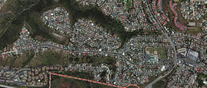

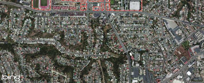
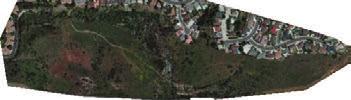
74 Project Site Document Path: Z:\Projects\j821101\MAPDOC\MAPS\EIR Figs\Section 1 PD\Fig2_Vicinity.pdf SDSU Campus and Existing Campus Master Plan Boundary Project Site ,000 Feet AERIAL SOURCE: BING MAPPING SERVICE Aesthetics Technical Report Figure 2a Vicinity Map


75 Document Path: Z:\Projects\j821101\MAPDOC\MAPS\EIR Figs\Section 1 PD\Fig3_Project Area Map.pdf SDSU Campus Boundary Project Site Feet AERIAL SOURCE: BING MAPPING SERVICE Project Site Aesthetics Technical Report Figure 2b Project Area Map

76 Feet Z:\Projects\j821101\MAPDOC\MAPS\EIR Figs COMMUNITY SOURCE: URS 2013 SDSU New Student Housing Aesthetics Technical Report Figure 3 Project Site Topography

77 RESIDENTIAL HALL 3 70 DIA. FIRE ACCESS TURNAROUND CUL DE SAC ARCADE WALKWAY EXISTING CHAPULTEC HALL RESIDENTIAL HALL1 CONCRETE RETAINING WALL - 20 ABOVE ADJACENT GRADE RESIDENTIAL HALL 2 SERVICE ENTRANCE AT FIRE LANE LEVEL RESIDENTIAL HALL1 RESIDENTIAL HALL 2 FOOD SERVICE BUILDING PULL OFF FOR PICK UP AND DROP OFF MAIN ENTRY TO DINING HALL 24/7 SECURED ENTRY TO RESIDENCE HALL 24/7 SECURED ENTRY TO RESIDENCE HALL N SOURCE: CARRIER JOHNSON 2013 RESIDENTIAL HALL 4 SDSU New Student Housing Aesthetics Technical Report Figure 4 Proposed Site Plan


78 North Fortuna 52 South Fortuna Kwaay Paay Peak Pyles Peak Cowles Mountain 8 Scenic Vistas Project Site SDSU Campus Boundary Figure 5 Aesthetics Technical Report Miles SOURCE: USGS 7.5-Minute Series La Mesa Mission Trails Regional Park: Scenic Vistas
4.1 AESTHETICS INTRODUCTION
 4.1 AESTHETICS 4.1.1 INTRODUCTION This section describes the existing visual setting of the project site and vicinity, identifies associated regulatory requirements, evaluates potential impacts, and identifies
Nob Hill Pipeline Improvements Project EIR
 Section 3.1 Aesthetics This section addresses the visual aspects that may affect the views experienced by the public, including the potential to impact the existing character of each area that comprises
IV. ENVIRONMENTAL IMPACT ANALYSIS B. AESTHETICS 1. VIEWS
 IV. ENVIRONMENTAL IMPACT ANALYSIS B. AESTHETICS 1. VIEWS ENVIRONMENTAL SETTING Existing Visual Character Project Site The project site is located at 10250 Wilshire Boulevard in the Westwood community of
CHAPTER 10 AESTHETICS
 CHAPTER 10 AESTHETICS CHAPTER 10 AESTHETICS This section identifies and evaluates key visual resources in the project area to determine the degree of visual impact that would be attributable to the project.
The impacts examined herein take into account two attributes of aesthetic values:
 IV. ENVIRONMENTAL IMPACT ANALYSIS This section addresses the potential impacts to views and aesthetics as a result of the proposed Project at the Project Site and the development scenarios analyzed for
5. Environmental Analysis
 5.1 This section of the Draft Environmental Impact Report (DEIR) describes the existing landform and aesthetic character of the project area and discusses the potential impacts to the visual character
5.1 AESTHETICS AND VISUAL RESOURCES Physical Setting
 5.1 AESTHETICS AND VISUAL RESOURCES 5.1.1 Physical Setting Aesthetic values are an important aspect in establishing the identity, sense of place, and quality of life in a community. Natural features in
VISUAL RESOURCES 1. INTRODUCTION 2. EXISTING CONDITIONS. a. Visual Character
 IV.A VISUAL RESOURCES 1. INTRODUCTION This section addresses the potential changes in visual character that would result from implementation of the proposed Wilshire and La Brea Project. Also evaluated
3.2 AESTHETICS/VISUAL QUALITY
 3.2 AESTHETICS/VISUAL QUALITY This section evaluates the potential impacts of the proposed project on the existing visual conditions within MTRP. Design features proposed to reduce or avoid adverse effects
Environmental Setting, Impacts, and Mitigation Measures
 CHAPTER 3 Environmental Setting, Impacts, and Mitigation Measures Format of the Environmental Analysis The assessment of each environmental resource discussed in this chapter includes the following: Environmental
3.1 Aesthetics, Light, and Glare
 3.1 3.1.1 Introduction This section describes the existing aesthetics, light, and glare setting and potential effects from project implementation on visual resources and the site and its surroundings.
ENVIRONMENTAL IMPACT ANALYSIS
 IV. ENVIRONMENTAL IMPACT ANALYSIS A. AESTHETICS This section addresses the potential impacts to aesthetics and views that could result from the proposed project, including development of the Add Area,
4.1 AESTHETICS AND VISUAL QUALITY
 SCOPE AND METHODOLOGY 4.1 AESTHETICS AND VISUAL QUALITY This section evaluates the potential impacts to aesthetics and visual quality. Aesthetics refers to visual resources and the quality of what can
New Student Housing Draft EIR Public Meeting
 New Student Housing Draft EIR Public Meeting May 8, 2017 Meeting Overview Purpose of Meeting Sophomore Success Project Objectives Alternatives Project Site/Design Overview Biological Resource Impacts/Mitigation
IV. ENVIRONMENTAL IMPACT ANALYSIS B. AESTHETICS
 IV. ENVIRONMENTAL IMPACT ANALYSIS B. AESTHETICS INTRODUCTION This section evaluates the potential impacts of the Proposed Project on aesthetics, views and vistas, light and glare, and shade and shadows
IV.B. VISUAL RESOURCES
 IV.B. VISUAL RESOURCES ENVIRONMENTAL SETTING Existing Visual Character Project Site The project site is located at 17331-17333 Tramonto Drive in the Pacific Palisades community of the City of Los Angeles
4.10 LAND USE AND PLANNING
 4.10 LAND USE AND PLANNING 4.10.1 INTRODUCTION This section considers the potential effects of the proposed New Student Housing Project (proposed project) relative to land use and planning. 4.10.2 METHODOLOGY
6.1 Aesthetics Introduction
 SECTION 6.0 ENVIRONMENTAL ANALYSIS 6.1 Aesthetics 6.1.1 Introduction The aesthetic quality of the proposed Project is determined by its visual character, consisting of elements such as natural and man-made
4.8 LAND USE AND PLANNING
 4.8 LAND USE AND PLANNING 4.8.1 INTRODUCTION This section describes existing and planned land uses at the Hayward campus and analyzes the impact of implementation of the proposed Master Plan on land uses
Visual Impact Assessment 830 Pratt Avenue St Helena, CA
 Visual Impact Assessment 830 Pratt Avenue St Helena, CA 1. Introduction The following aesthetic visual impact assessment has been prepared pursuant to the California Environmental Quality Act (CEQA). The
4.1 AESTHETICS WATSON INDUSTRIAL PARK ENVIRONMENTAL IMPACT REPORT EXISTING CONDITIONS
 This Subsection describes the aesthetic qualities and visual resources present on the Project site and in the site s vicinity and evaluates the potential effects that the Project may have on these resources.
RZC Public View Corridors and Gateways
 RZC 21.42 Public View Corridors and Gateways 21.42.010 Purpose 21.42.020 Scope and Authority 21.42.030 Administration 21.42.040 Gateways Design 21.42.050 Unidentified Public Views 21.42.060 Identification
IV. ENVIRONMENTAL IMPACT ANALYSIS B. AESTHETICS 1. SHADE/SHADOW
 IV. ENVIRONMENTAL IMPACT ANALYSIS B. AESTHETICS 1. SHADE/SHADOW ENVIRONMENTAL SETTING The issue of shade and shadow pertains to the blockage of direct sunlight by onsite buildings, which affect adjacent
4.1 AESTHETICS EXISTING ENVIRONMENTAL SETTING ALAMITOS BAY MARINA REHABILITATION PROJECT CITY OF LONG BEACH
 4.1 AESTHETICS This section provides a discussion of the existing visual and aesthetic resources on site and in the surrounding area as well as an analysis of potential impacts from implementation of the
3.1 AESTHETICS AND VISUAL RESOURCES
 3.1 AESTHETICS AND VISUAL RESOURCES This section examines the potential for the proposed Project to create aesthetic and visual impacts as defined by the California Environmental Quality Act (CEQA) as
APPENDIX C. Architectural and Environmental Design Standards. Environmentally sensitive areas should be protected.
 APPENDIX C Architectural and Environmental Design Standards Environmentally Sensitive Areas Goal A. Environmentally sensitive areas should be protected. Development, such as roads, houses, and other structures,
DRAFT ENVIRONMENTAL IMPACT REPORT DEEP VALLEY DRIVE AND INDIAN PEAK ROAD MIXED-USE RESIDENTIAL PROJECT
 LSA ASSOCIATES, INC. JUNE 2012 SECTION 4.1 AESTHETICS DRAFT ENVIRONMENTAL IMPACT REPORT 4.1 AESTHETICS Introduction This section provides a discussion of the existing visual and aesthetic resources on
5.11 AESTHETICS ENVIRONMENTAL SETTING
 5.11 AESTHETICS ENVIRONMENTAL SETTING The lies on a relatively flat valley floor surrounded by rugged hills and mountains. The topography of the planning area is defined by the Box Springs Mountains and
3.1 AESTHETICS Background and Methodology
 3.1 AESTHETICS 3.1.1 Background and Methodology 3.1.1.1 Regulatory Context The California Environmental Quality Act (CEQA) requires that project sponsors evaluate the project s potential to cause aesthetic
Harvard-Westlake Parking Improvement Plan, Lighting Evaluation, Lighting Design Alliance, September 25, 2013 (Appendix I)
") 3.1 AESTHETICS The purpose of this section is to characterize the visual (aesthetic) environment that currently exists in the Project area and to identify potential impacts to: visual character, views
3.1 AESTHETICS The purpose of this section is to characterize the visual (aesthetic) environment that currently exists in the Project area and to identify potential impacts to: visual character, views
Section 3.16 Visual Quality
 Chapter 3 Affected Environment, Environmental Consequences, and Mitigation Measures Section 3.16 Visual Quality Introduction This section discusses existing conditions, effects and mitigation measures
IV. ENVIRONMENTAL IMPACT ANALYSIS
 IV. ENVIRONMENTAL IMPACT ANALYSIS A. AESTHETICS/VIEWS EXISTING CONDITIONS REGIONAL SETTING The project area (between Devonshire Street and the SR-118 freeway) is generally characterized by single-family
PROJECT SITE The Proposed Project includes the Allen and Pike Street malls between Delancey and South Streets (see Figure 2C-1).
.") Chapter 2, Section C: A. INTRODUCTION This chapter considers the potential of the proposed Reconstruction of the Allen and Pike Street Malls project to affect the urban design characteristics and visual
Chapter 2, Section C: A. INTRODUCTION This chapter considers the potential of the proposed Reconstruction of the Allen and Pike Street Malls project to affect the urban design characteristics and visual
3.10 LAND USE SETTING PROJECT SITE EXISTING LAND USE DESIGNATIONS AND ZONING. General Plan Land Use Designations.
 This section of the Draft EIR addresses the existing land uses on and adjacent to the project site and discusses the potential impacts of the proposed project on existing land uses. Key issues addressed
California Department of Transportation, California Scenic Highway Program; Placer Vineyards Specific Plan EIR prepared by Placer County;
 3.1 AESTHETICS 3.1.1 INTRODUCTION This section describes the visual character of the project site and views from surrounding public areas. This section also evaluates the change to visual resources in
MASTER PLAN. 201 Planning Concepts. Chapter 2
 Chapter 2 MASTER PLAN 201 Planning Concepts 202 Master Land Use Plan 203 Affordable Housing Program 204 Parks, Open Space, and Recreation Trails 205 Grading Concept 206 Circulation Plan 207 Landscape Concept
This section describes the existing conditions in the project area and identifies the resources that could be affected by the project.
 4.4 VISUAL RESOURCES The following analysis identifies changes in the visual environment experienced by existing offsite viewers with exposure to the site of the Mitchell Farms Subdivision (project). In
IV. ENVIRONMENTAL IMPACT ANALYSIS B. AESTHETICS 1. AESTHETICS/VIEWS
 IV. ENVIRONMENTAL IMPACT ANALYSIS B. AESTHETICS 1. AESTHETICS/VIEWS ENVIRONMENTAL SETTING Aesthetic impact assessment generally deals with the issue of contrast, or the degree to which elements of the
APPENDIX D: Visual and Aesthetic Conditions for NCCU Station Refinement. Durham-Orange Light Rail Transit Project
 APPENDIX D: Visual and Aesthetic Conditions for NCCU Station Refinement Durham-Orange Light Rail Transit Project October 2016 1. Introduction The Combined FEIS/ROD summarizes the effects of the D-O LRT
1. INTRODUCTION. a. Light. b. Glare
 IV.A.2 LIGHT & GLARE 1. INTRODUCTION This section describes the existing sources of nighttime illumination and glare on the Project site and in the surrounding area and evaluates potential changes resulting
B. AESTHETICS. 1. Setting
 This section evaluates the effects of the proposed project on the aesthetics of the project site and its surroundings. This analysis also considers the consistency of the proposed project with applicable
Glenn Highway MP DSR. Landscape Narrative
 Glenn Highway MP 34-42 DSR Landscape Narrative Project Landscape Goals The Glenn Highway MP 34-42 Project extends through a variety of landscape types typical to the Matanuska-Susitna Valley. In general,
2.2.2 Mixed Urban/Community Core Districts
 corridor is visible only from streets that cross them. In others, the rights-of-way are paralleled by frontage roads from which the rail corridors are fully visible to road users. The views within the
Visual and Aesthetics
 Such a connection could accommodate timed transfers and improve connections between local transit service and Presidio Shuttle service. Level of Service The results of the analysis are provided on a route-by-route
V. ENVIRONMENTAL IMPACT ANALYSIS A. Aesthetics
 A. AESTHETICS Aesthetic impacts for the project have been evaluated under two general categories: 1) Visual Character and Scenic Views, which addresses the general aesthetic value and view impacts relative
IV. ENVIRONMENTAL IMPACT ANALYSIS
 IV. ENVIRONMENTAL IMPACT ANALYSIS IV. ENVIRONMENTAL IMPACT ANALYSIS A. AESTHETICS AND VIEWS 1. INTRODUCTION This section analyzes the potential impacts that could result from the proposed project with
5.8 Visual Resources and Aesthetic Qualities
 I-70 East Supplemental Draft EIS 5.8 Visual Resources and Aesthetic Qualities 5.8 Visual Resources and Aesthetic Qualities This section discusses the visual resources and aesthetic qualities of the study
3.1.1 Aesthetics. 3.1 Effects Not Found Significant as Part of the EIR Process
 CHAPTER 3 EFFECTS NOT FOUND TO BE SIGNIFICANT 3.1 Effects Not Found Significant as Part of the EIR Process This section addresses the potential aesthetics and visual resources impacts associated with implementation
4.0 AFFECTED ENVIRONMENT AND ENVIRONMENTAL CONSEQUENCES
 4.0 AFFECTED ENVIRONMENT AND ENVIRONMENTAL CONSEQUENCES The following sections discuss the impacts associated with environmental resources for the tunneling method Alternatives A and B. The construction
6.3 VISUAL RESOURCES. Landscape Character
 6.3 VISUAL RESOURCES 6.3.1 Affected Environment The DMR discussion is divided into two areas, DMR and Dillingham Trail, which would extend from SBMR to DMR. The ROI includes all areas within the line of
WESTSIDE SUBWAY EXTENSION PROJECT. Addendum to the Visual and Aesthetic Impacts Technical Report
 PROJECT to the Visual and Aesthetic Impacts Technical Report August 2011 Visual and Aesthetic Impacts Technical Report SUMMARY On October 28, 2010, the Metro Board selected the Westwood/VA Hospital Extension
Policies and Code Intent Sections Related to Town Center
 Policies and Code Intent Sections Related to Town Center The Town Center Vision is scattered throughout the Comprehensive Plan, development code and the 1994 Town Center Plan. What follows are sections
920 BAYSWATER AVENUE PROJECT
 920 BAYSWATER AVENUE PROJECT VISUAL ASSESSMENT Prepared for the City of Burlingame Prepared by Circlepoint 46 S First Street, San Jose, CA 95113 June 2018 This page intentionally left blank. 920 Bayswater
Jordan Harrison, Planner III, San Francisco Recreation and Park Department
 Date December 8, 2015 To: Through: From: Subject: Recreation and Park Commission Philip A. Ginsburg, General Manager Dawn Kamalanathan, Director, Capital & Planning Division Jordan Harrison, Planner III,
3.7 Aesthetics. A. Setting. 1. Existing Views of the Quarry
 3.7 Aesthetics A. Setting 1. Existing Views of the Quarry The existing quarry is visible from Highway 101 and from locations on the Ridgewood Ranch to the south. It is also possibly visible from distant
SECTION 5.1 Aesthetics, Light, and Glare
 SECTION 5.1 Aesthetics, Light, and Glare 5.1 AESTHETICS, LIGHT, AND GLARE Visual resources information for this section was compiled from photographs and site surveys conducted by RBF Consulting. The purpose
2.0 AREA PLANS. Lakeside Business District. Lakeside Business District Land Use Categories:
 Lakeside Business District Lakeside Business District Land Use Categories: Campus Commercial Campus Commercial means a mixture of uses which includes corporate offices, office parks, hotels, commercial,
Policy I-G-7: Public access to the Bay for the scenic enjoyment of the open water, sloughs, and marshes shall be protected.
 3.3 AESTHETICS Introduction This section describes the existing aesthetic resources and visual characteristics of the Project site and its immediate vicinity, along with existing plans and policies that
7.5 Impacts on the Section 4(f) Properties
 Properties") constructive use, such as noise, air quality and visual impacts were also assessed. It was determined that this project would not introduce changes of an external nature that would affect the recreational
constructive use, such as noise, air quality and visual impacts were also assessed. It was determined that this project would not introduce changes of an external nature that would affect the recreational
Gold Line Bus Rapid Transit Transit Oriented Development (BRTOD) Helmo Station Area Plan
 Helmo Station Area Plan") Appendix F Gold Line Bus Rapid Transit Transit Oriented Development (BRTOD) Helmo Station Area Plan Introduction and Purpose of the Plan The Gold Line Bus Rapid Transit facility is an eleven-mile dedicated
Appendix F Gold Line Bus Rapid Transit Transit Oriented Development (BRTOD) Helmo Station Area Plan Introduction and Purpose of the Plan The Gold Line Bus Rapid Transit facility is an eleven-mile dedicated
4.1 AESTHETICS INTRODUCTION METHODOLOGY
 LSA ASSOCIATES, INC. R ECIRCULATED DRAFT ENVIRONMENTAL IMPACT REPORT 4.1 AESTHETICS 4.1.1 INTRODUCTION This section defines the existing visual setting on and in the vicinity of the project site and analyzes
3A. Aesthetics. 3A.1 Environmental Setting. Regional Character. Project Site
 The purpose of this section is to identify and evaluate key visual resources in the project area from public viewpoints, and to determine the degree of visual impacts that could occur if the proposed project
I. VISUAL/AESTHETICS/NEIGHBORHOOD CHARACTER. b. Existing Conditions Views from Kimball Avenue
 I. VISUAL/AESTHETICS/NEIGHBORHOOD CHARACTER 1. Existing Conditions a. View Of The Site From Area Roads Figures IV.I-2, I-3 and I-4 depict existing views from the Cross County Parkway, Central Park Avenue,
3.6 VISUAL/AESTHETICS
 3.6 VISUAL/AESTHETICS The information in this section is based on the I-710 Corridor Project Visual Impact Assessment (VIA) (December 2011) and Urban Design and Aesthetics Toolbox Report (February 2012).
GENERAL PLAN CONSISTENCY ANALYSIS
 GENERAL PLAN CONSISTENCY ANALYSIS Prepared by Planning Staff 10/28/2013 APPLICABLE GOALS, POLICIES AND PROGRAMS FROM the LAND USE CHAPTER Goal LU-1 Policy LU-1.1 Policy LU-1.2 Goal LU-2 Protect the character
4.1 AESTHETICS Environmental Setting
 4.1 AESTHETICS This section of the Focused Tiered Final EIR presents potential aesthetic impacts of the Creative Arts and Holloway Mixed-Use Project (Project). Preparation of this Focused Tiered Final
3. ENVIRONMENTAL SETTING, IMPACTS, AND MITIGATION MEASURES
 3. ENVIRONMENTAL SETTING, IMPACTS, AND MITIGATION MEASURES Organization of this Chapter This chapter presents the environmental setting of the project for the various impact categories, and then evaluates
4.1 Aesthetics Setting. a. Visual Character
 Environmental Impact Analysis Aesthetics 4.1 Aesthetics This section analyzes the proposed Specific Plan s impacts related to aesthetics, including the existing visual character of and scenic views in
4.8 Landform Alteration and Aesthetics
 4.8 Landform Alteration and Aesthetics 4.8 LANDFORM ALTERATION AND AESTHETICS This section describes the potential environmental effects related to temporary and permanent impacts to landform and aesthetics,
Town Center. Block 5 Existing multifamily residential units are expected to remain.
 Area Guidelines Germantown s districts should be developed as distinct communities with unique features that are supported through the guidelines. The guidelines not only help distinguish these districts
5.1 AESTHETICS AND VISUAL RESOURCES
 5.1 AESTHETICS AND VISUAL RESOURCES This section describes the existing visual environment in and around the project area. The analysis assesses the potential for aesthetics/light and glare impacts using
IV. Environmental Impact Analysis B. Aesthetics. 1. Visual Quality/Views. a. Introduction
 IV. Environmental Impact Analysis B. Aesthetics 1. Visual Quality/Views a. Introduction This section addresses the potential impacts that could result from the Proposed Project with regard to visual quality
CHAPTER 3. Design Standards for Business, Commercial, Industrial, Recreational and Institutional Uses
 CHAPTER 3 Design Standards for Business, Commercial, Section Number Title Ordinance Number Date of Ordinance 16-3-1 Applicability 2006-11 2008-04 07-01-08 16-3-2 Uniform Standards for Architectural Design
MULTIFAMILY RESIDENTIAL DESIGN PRINCIPLES Site Plan and Design Review Principles Checklist
 MULTIFAMILY RESIDENTIAL DESIGN PRINCIPLES Site Plan and Design Review Principles Checklist Applicant s Name: Project Address: Phone: Email: Applicant shall fill out the design guidelines checklist for
There are no federal programs or policies addressing visual resources that pertain to the 2018 LRDP.
 3.1 AESTHETICS This section describes the existing visual characteristics of the plan area and evaluates the potential of the 2018 LRDP to result in substantial adverse visual impacts. The visual impact
3.5 VISUAL AND AESTHETIC QUALITIES
 3.5 VISUAL AND AESTHETIC QUALITIES 3.5.1 Introduction to Analysis 3.5.1.1 Summary of Results The Preferred Alternative would represent a minimal change to the visual character of the existing rail corridor.
6.8 SCENIC HIGHWAYS Introduction
 6.8 SCENIC HIGHWAYS 6.8.1 Introduction The Scenic Highways Element is an optional General Plan element authorized by Section 65303 of the Government Code. The Scenic Highways Element is intended to establish
PLANNING RATIONALE FOR THE PROPOSED RIVERSIDE SOUTH ELEMENTARY SCHOOL 715 BRIAN GOOD AVENUE, OTTAWA, ON
 PLANNING RATIONALE FOR THE PROPOSED RIVERSIDE SOUTH ELEMENTARY SCHOOL 715 BRIAN GOOD AVENUE, OTTAWA, ON Conseil des écoles publiques de l'est de l'ontario (CEPEO) French Public School Board TABLE OF CONTENTS
WEST LOOP DESIGN GUIDELINES CHECKLIST
 WEST LOOP DESIGN GUIDELINES CHECKLIST Section 1.0 General Strategies 1.1 DESIGN EXCELLENCE: ENCOURAGE HIGH QUALITY AND INNOVATIVE DESIGN OF NEW BUILDINGS WITHIN THE WEST LOOP WITHOUT BEING PRESCRIPTIVE
4.8 Land Use and Planning Environmental Setting Impacts and Mitigation Measures References...4.
 TABLE OF CONTENTS 4.8 Land Use and Planning...4.8-1 4.8.1 Environmental Setting...4.8-1 4.8.2 Impacts and Mitigation Measures...4.8-5 4.8.3 References...4.8-11 FIGURES Figure 4.8-1 Figure 4.8-2 Figure
4.1 AESTHETICS. Table Impact and Mitigation Summary: Aesthetics. Impact Mitigation Measures Residual Impact
 4.1.1 Summary 4.1 AESTHETICS Table 4.1-1 summarizes the identified environmental impacts, proposed mitigation measures, and residual impacts of the proposed project with regard to aesthetics. Additional
ATTACHMENT A. SILVERDALE DESIGN STANDARDS Amendments to the Waaga Way Town Center Chapter
 ATTACHMENT A SILVERDALE DESIGN STANDARDS Amendments to the Waaga Way Town Center Chapter Chapter 10. Waaga Way Town Center 10.1 Physical Identity Elements & Opportunities The Waaga Way Town Center includes
Town of Portola Valley General Plan. Nathhorst Triangle Area Plan
 Town of Portola Valley General Plan Amended December 10, 1997 Table of Contents Introduction... 1 Planning Area... 1 Objectives... 2 Principles... 2 Standards... 4 Description... 4 Community Commercial...
ENVIRONMENTAL IMPACT ANALYSIS A. AESTHETICS 1. INTRODUCTION
 IV. ENVIRONMENTAL IMPACT ANALYSIS 1. INTRODUCTION Aesthetics, views, nighttime illumination, and daytime glare are related elements in the visual environment. Aesthetics generally refers to the identification
CHAPTER FIVE COMMUNITY DESIGN
 CHAPTER FIVE COMMUNITY DESIGN CHAPTER FIVE - COMMUNITY DESIGN Assumptions Frazier Park and Lebec have historically developed according to different patterns of spatial form. While both communities are
Standards (R-3) Figure B-11: R-3 Residential Standards Exhibit
 Figure B-11: R-3 Residential Standards Exhibit") Avila Ranch Avila Ranch Specific Plan Development Standards High Medium Density - High Residential Density Residential Lot and Building Lot and Standards Building (R-3) Standards (R-3) EXAMPLES These sketches
Avila Ranch Avila Ranch Specific Plan Development Standards High Medium Density - High Residential Density Residential Lot and Building Lot and Standards Building (R-3) Standards (R-3) EXAMPLES These sketches
IV. ENVIRONMENTAL IMPACT ANALYSIS B. AESTHETICS
 IV. ENVIRONMENTAL IMPACT ANALYSIS B. AESTHETICS ENVIRONMENTAL SETTING Surrounding Area The project site is located at the eastern edge of the Verdugo Mountains in the community of Sunland- Tujunga. Although
Appendix E Section 4(f) Evaluation
 Evaluation") Appendix E Section 4(f) Evaluation Appendix E Draft Section 4(f) Evaluation E.1 Introduction This appendix addresses a federal regulation known as Section 4(f), which protects parks, recreation areas,
Appendix E Section 4(f) Evaluation Appendix E Draft Section 4(f) Evaluation E.1 Introduction This appendix addresses a federal regulation known as Section 4(f), which protects parks, recreation areas,
Preci nct P l ans Figure 56 Campus Aerial Photo, 2008 CAL STATE EAST BAY, HAYWARD CAMPUS MASTER PLAN
 9 Precinct Plans This section contains a detailed discussion of the planning and design concepts for specific areas or precincts of the Cal State East Bay Hayward campus. The Precinct Plans pertain to
IV. ENVIRONMENTAL IMPACT ANALYSIS B. AESTHETICS 1. VIEWS
 IV. ENVIRONMENTAL IMPACT ANALYSIS B. AESTHETICS 1. VIEWS INTRODUCTION This section evaluates the potential impacts of the Proposed Project on aesthetics, views and vistas, light and glare, and shade and
NEIGHBORHOOD 7: FEE LANE AREA. Aerial View of Briscoe and McNutt Dormitories
 NEIGHBORHOOD 7: FEE LANE AREA Aerial View of Briscoe and McNutt Dormitories Fee Lane Area Map Briscoe Dormitory 278 neighborhoods NEIGHBORHOOD 7: FEE LANE AREA EXISTING CHARACTER The Fee Lane Area neighborhood
Neighborhood Districts
 NEIGHBORHOOD DISTRICTS SEVEN MAIN DISTRICTS Neighborhood Districts While the Development Plan provides a broad-scale overview of the neighborhood, this section focuses on uses and relationships at the
Urban Design Brief December 23, 2015 Southside Construction Group Official Plan & Zoning By-Law Amendment
 Urban Design Brief Proposed Official Plan & Zoning By-Law Amendment 3244, 3263 and 3274 Wonderland Road South Southside Group December 23, 2015 TABLE OF CONTENTS Page No. INTRODUCTION... 1 SECTION 1 LAND
VILLAGE OF SKOKIE Design Guidelines for Mixed-Use Districts NX Neighborhood Mixed-Use TX Transit Mixed-Use CX Core Mixed-Use
 VILLAGE OF SKOKIE Design Guidelines for Mixed-Use Districts NX Neighborhood Mixed-Use TX Transit Mixed-Use CX Core Mixed-Use TABLE OF CONTENTS CHAPTER 1 SITE DESIGN Purpose 1 CHAPTER 2 SITE DESIGN Streetscape
Silverlakes Equestrian Sports Park Draft Environmental Impact Report
 Silverlakes Equestrian Sports Park Draft Environmental Impact Report Aesthetics 4.1 - Aesthetics 4.1.1 - Introduction This section describes the existing aesthetic setting and potential effects from project
ARTICLE 13 STREETS General
 ARTICLE 13 STREETS 13.1 General Streets shall be designed to suit their functions. Many streets have purposes other than vehicular traffic. As an alternative to current N.C. Department of Transportation
Chapter 1 - General Design Guidelines CHAPTER 1 GENERAL DESIGN GUIDELINES
 CHAPTER 1 GENERAL DESIGN GUIDELINES 1.0 INTRODUCTION This Publication has been developed to provide current, uniform procedures and guidelines for the application and design of safe, convenient, efficient
Urban Design Brief 1576 Richmond Street City of London
 Urban Design Brief City of London Treadstone Developments October 31, 2014 Urban Design Brief October 31, 2014 TABLE OF CONTENTS Page No. INTRODUCTION... 1 SECTION 1 LAND USE PLANNING CONCEPT... 1 1.1
ARTICLE 13 STREETS General
 ARTICLE 13 STREETS 13.1 General Streets shall be designed to suit their functions. Many streets have purposes other than vehicular traffic. As an alternative to current N.C. Department of Transportation
4.1 AESTHETICS/VISUAL RESOURCES
 4.1 AESTHETICS/VISUAL RESOURCES This section provides a discussion of the visual resources in and around the project site, with an emphasis on the visual character and scenic qualities of the Gaviota Coast