CHAPTER 5 - STORMWATER "URBAN SERVICES STANDARDS AND GUIDELINES" CITY OF PORT ANGELES - PUBLIC WORKS & UTILITIES DEPARTMENT
|
|
|
- Blaise Phillips
- 5 years ago
- Views:
Transcription
1 5.01 PURPOSE AND POLICY CHAPTER 5 - STORMWATER "URBAN SERVICES STANDARDS AND GUIDELINES" CITY OF PORT ANGELES - PUBLIC WORKS & UTILITIES DEPARTMENT The purpose of these standards and requirements is to protect water quality in all of the streams and local water bodies, and to control connections to the City s stormwater system. The standards in this chapter are intended to be applied by the City Engineer while reviewing proposed stormwater facilities and stormwater discharges pursuant to Port Angeles Municipal Code (PAMC), Sections and They are intended to implement the most recent version of the Department of Ecology s Stormwater Manual for Western Washington 2014 (SWMMWW [2014]), and represent the minimum standards for the design and construction of permanent stormwater facilities in the City of Port Angeles. They clarify, and in some cases strengthen, the Department of Ecology s SWMMWW (2014) Best Management Practices (BMPs) for use within the City. In the case of conflict between the Urban Services Standards and Guidelines and the Department of Ecology s SWMMWW (2014), the more stringent standard will apply STORMWATER PERMITTING All Building Permits and Clearing and Grading Permits shall comply with all standards, thresholds and requirements established in this Chapter, by City Ordinance and the Department of Ecology s SWMMWW (2014). Any new development or redevelopment which does not trigger a Building Permit or Clearing and Grading Permit but which discharges runoff either directly or indirectly to the City s stormwater system will be required to obtain a Construction Stormwater Discharge Permit which shall comply with all standards, thresholds and requirements established in this Chapter, by City ordinance and the Department of Ecology s SWMMWW (2014). All discharges not composed of entirely stormwater may require a Non-Construction Stormwater Discharge Permit Building Permit and Clearing and Grading Permit A. All new development or redevelopment that requires a building permit or Clearing and Grading Permit shall be evaluated by the thresholds in Figures 5.1, and 5.2. All applicable standards and requirements as set forth in this Chapter shall be attached to the Building Permit or Clearing and Grading Permit. B. Fees for stormwater review, inspection and storm drain connections shall be charged through the Building Permit or Clearing and Grading Permit per the current schedule of fees in PAMC C. The Permittee shall comply with the following minimum conditions when triggering Minimum Requirements (MR) # 1-5 or all MR in Figures 5.1 and 5.2: Submit a stormwater plan for review and approval. Requirements for stormwater plans are detailed in Section Notify the City at least 48 hours before commencing the stormwater work. Notify the City at least 48 hours before tying into the City s stormwater system. Install stormwater facilities as shown in the approved stormwater plan. Obtain approval in writing from the City for any stormwater plan revisions. Provide safe access to allow the City to enter the site for the purpose of inspecting stormwater facilities for compliance with the approved stormwater plan. Keep an up-to-date copy of the approved stormwater plan on site during working hours. Ensure that all workmanship and materials are in accordance with these Standards, the most recent version of the Department of Ecology s SWMMWW (2014) and the Washington State Department of Transportation (WSDOT) Standard Specifications for Road, Bridge and Municipal Construction. Construction within environmentally sensitive areas or their buffers shall be in compliance with Chapter 15 of the PAMC, and is subject to the review and authority of the Director of Community and Economic Development. D. Projects that result in less than 2,000 square feet of new plus replaced hard surface, less than 7,000 square feet of land-disturbing activity, AND grades/fills less than 100 cubic yards are not required to prepare a Construction SWPPP, but must consider all 13 elements of Construction Stormwater Pollution Prevention and development controls for all elements that pertain to the project site Construction Stormwater Discharge Permit Chapter 5 Stormwater (January 2017) Page 1 of 31
2 CHAPTER 5 - STORMWATER A. A Construction Stormwater Discharge Permit will be required for the following activities: B. All new development or redevelopment that triggers minimum requirements in Figures 5.1, and 5.2 that does not require a Building Permit or a Clearing and Grading Permit or new and replaced stormwater connections to the City stormwater system. The Construction Stormwater Discharge Permit will be effective for twelve months from the date of issuance, but may, with due cause, be extended for an additional twelve month period. C. The fee schedule for the review of plans for new development or redevelopment will be set by resolution of the City Council. A current schedule of fees is included in PAMC D. The Permittee shall comply with the following minimum conditions for Construction Stormwater Discharge Permits: Submit a stormwater plan for review and approval. Requirements for stormwater plans are detailed in Section Notify the City at least 48 hours before commencing the stormwater work. Notify the City at least 48 hours before tying into the City s stormwater system. Install stormwater facilities as shown in the approved stormwater plan. Obtain approval in writing from the City for any stormwater plan revisions. Provide safe access to allow the City to enter the site for the purpose of inspecting stormwater facilities for compliance with the approved stormwater plan. Keep an up-to-date copy of the approved stormwater plan on site during working hours. Ensure that all workmanship and materials are in accordance with these Standards, the most recent version of the Department of Ecology s SWMMWW (2014)and the WSDOT Standard Specifications for Road, Bridge and Municipal Construction. Construction within environmentally sensitive areas or their buffers shall be in compliance with Chapter 15 of the PAMC, and is subject to the review and authority of the Director of Community and Economic Development Non-Construction Stormwater Discharge Permit A. A Non-Construction Stormwater Discharge Permit will be required for specific activities that affect stormwater by discharging runoff either directly or indirectly to the City s stormwater system and that do not require a Construction Stormwater Discharge Permit. Activities that will require a Non-Construction Stormwater Discharge Permit include: Draining water from a chlorinated water source such as a swimming pool, spa, or a hot tub. Charity car washes that are not permitted as a commercial or industrial use. Building and sidewalk washing Other non-stormwater discharges not specifically mentioned B. The Non-Construction Stormwater Discharge Permit will be effective for six months from the date of issuance, but may with due cause be extended for an additional six month period. C. No fee will be required for Non-Construction Stormwater Discharge Permits. D. The Permitee shall comply with the following minimum conditions for Non-Construction Stormwater Discharge Permits: Comply with whatever measure(s) the City deems necessary to keep wash water and chemicals from entering a storm drain or creek. Notify the City 48 hours before commencing activity. Chapter 5 Stormwater (January 2017) Page 2 of 31
3 CHAPTER 5 - STORMWATER 5.03 APPLICABILITY AND EXEMPTIONS All new development and redevelopment projects must be evaluated through the following flow charts (Figures 5.1 and 5.2 below) to determine which of the nine Minimum Requirements will apply (see Section 5.04), unless the project meets one of the following general exemptions: 1. Forest practices regulated under Title 222 WAC, except for Class IV General forest practices that are conversions from timberland to other uses. 2. Commercial agriculture practices involving working the land for production, except for the conversion from timberland to agriculture, and the construction of impervious surfaces. 3. Oil and gas field activities or operations in the following specific categories: Construction of drilling sites, waste management pits, and access roads Construction of transportation and treatment infrastructure such as pipelines, natural gas treatment plants, natural gas pipeline compressor stations, and crude oil pumping stations. 4. Pavement maintenance in the following specific categories: Pothole and square cut patching that is less than 35% of the total project surface area, Overlaying existing asphalt or concrete pavement with asphalt or concrete pavement without expanding the area of coverage, Shoulder grading, Reshaping/regrading drainage systems, Crack sealing, Resurfacing with in-kind material without expanding the road prism, pavement preservation activities that do not expand the road prism, and Vegetation maintenance. The following pavement maintenance practices are not categorically exempt: o o o o o Overlaying or resurfacing which upgrades from dirt to gravel, asphalt, or concrete; upgrades from gravel to asphalt or concrete; or upgrades from a bituminous surface treatment (or chip seal) to asphalt or concrete. Removing and replacing a paved surface to base course or lower Repairing the pavement base Extending the pavement edge without increasing the size of the road prism Paving graveled shoulders 5. Underground utility projects that replace the ground surface with in-kind material or materials with similar runoff characteristics are only subject to Minimum Requirement #2. Before the developer proceeds with an exemption, the exemption must be discussed with and approved by the City Engineer. Chapter 5 Stormwater (January 2017) Page 3 of 31
4 CHAPTER 5 - STORMWATER 5.2 Figure 5.1. Flow Chart for Determining Requirements for New Development Chapter 5 Stormwater (January 2017) Page 4 of 31
5 CHAPTER 5 - STORMWATER Figure 5.2. Flow Chart for Determining Requirements for Redevelopment Chapter 5 Stormwater (January 2017) Page 5 of 31
6 CHAPTER 5 - STORMWATER 5.04 NINE MINIMUM REQUIREMENTS This section describes the nine Minimum Requirements (MR) for stormwater management for development and redevelopment sites that meet the disturbance thresholds in Figures 5.1 and 5.2. MINIMUM REQUIREMENTS #1 - #5 (REQUIRES SMALL PROJECT STORMWATER PLAN) ALL MINIMUM REQUIREMENTS (#1-#9) (REQUIRES LARGE PROJECT STORMWATER PLAN #1 Preparation of Stormwater Site Plans #1 Preparation of Stormwater Site Plans #2 Construction Stormwater Pollution Prevention #2 Construction Stormwater Pollution Prevention #3 Source Control of Pollution #3 Source Control of Pollution #4 Preservation of Natural Drainage Systems #4 Preservation of Natural Drainage Systems #5 On-site Stormwater Management #5 On-site Stormwater Management #6 Runoff Treatment #7 Flow Control #8 Wetland Protection #9 Operation and Maintenance Minimum Requirement #1: Preparation of Stormwater Site Plans The Stormwater Site Plan is a comprehensive report that contains all of the technical information and analysis necessary for the City to evaluate a proposed new development or redevelopment for compliance with stormwater requirements. The City requires a Small Project Stormwater Plan for projects that trigger MR #1 through #5 and a Large Project Stormwater Plan for projects that trigger MR #1 through #9. Both types of stormwater plans may require the following components: 1. Site Analysis: Collect and Analyze Information on Existing Conditions 2. Prepare Preliminary Development Layout 3. Perform Off site Analysis 4. Determine Applicable Minimum Requirements 5. Prepare a Permanent Stormwater Control Plan 6. Prepare a Construction Stormwater Pollution Prevention Plan 7. Complete the Stormwater Site Plan 8. Check Compliance with All Applicable Minimum Requirements State law requires that engineering work be performed by or under the direction of a professional engineer licensed to practice in Washington State. Plans involving construction of treatment facilities or flow control facilities (e.g., Chapter 5 Stormwater (January 2017) Page 6 of 31
7 CHAPTER 5 - STORMWATER detention ponds or infiltration basins), structural source control BMPs, or drainage conveyance systems generally involve engineering principles and should be prepared by or under the direction of a licensed engineer. Construction Stormwater Pollution Prevention Plans (SWPPPs) that involve engineering calculations must also be prepared by or under the direction of a licensed engineer. Note that in general, Small Project Stormwater Plans (described below in Section ) do not require the use of an engineer, but may require the use of a professional surveyor, soils scientist or other professional. However, Large Project Stormwater Plans (described below in Section ) require the use of an engineer, soils scientist, and/or professional land surveyor REQUIREMENTS FOR THE SMALL PROJECT STORMWATER PLAN Small Project Stormwater Plans are required for all new development and redevelopment projects that 1) meet Minimum Requirements (MR) #1 through #5 thresholds but do not trigger MR #6 through #9, and 2) have drainage elements that connect either directly or indirectly into the City s stormwater system, discharge directly to creeks, discharge to the Strait of Juan de Fuca, or discharge to groundwater. The City s stormwater system includes all natural and man-made systems which function together or independently to collect, store, purify, discharge, and convey stormwater. This plan represents a minimum requirement. The City may require the project proponent to meet the requirements of the Large Project Stormwater Plan if it is likely that the project will have a negative impact on water quality or quantity in a local stream. Small Project Stormwater Plans must be designed in accordance with PAMC as described in this Chapter. The plans will be reviewed to meet the submittal requirements in Urban Services Standards and Guidelines Chapter 1, Appendix J (Plan Review Checklist). The plans shall include the elements summarized in Table 5.1, or a written explanation of why the requirement does not apply to the project. The Small Project Stormwater Plan is required to include the following: Table 5.1. Small Project Stormwater Plan Requirements. Submittal Document Prepared By Reference Survey May require registered land surveyor (or other qualified professional). Check with City before proceeding. SWMMWW Volume I, Section (MR #1-5) Professional soil scientist certified by the Soil Science Society of America (or an equivalent national program), On-site sewage designer certified by Clallam County, or Soils report Other suitably trained persons working under the supervision of a professional engineer, geologist, hydrogeologist, or engineering geologist registered in the State of Washington SWMMWW Volume 1, Section (MR #1-5) Project Proponent may use City Infiltration Test Worksheet for projects resulting in less than 3000 sq-ft hard surface. Survey of existing native vegetation cover (for proposed native soil and vegetation protection areas) May require licensed architect, arborist, or qualified biologist. Check with City before proceeding. SWMMWW Volume 1, Section Chapter 5 Stormwater (January 2017) Page 7 of 31
8 CHAPTER 5 - STORMWATER Table 5.1. Small Project Stormwater Plan Requirements. Submittal Document Prepared By Reference Tabular list of the following: New hard surface areas Replaced hard surface areas Converted pervious surface areas Project proponent SWMMWW Volume 1, Section and Scale drawing of the following: Lot(s) Public right-of-way Location of LID facilities/bmps Areas served by LID facilities/bmps Project proponent SWMMWW Volume 1, Section (MR #1-5) Design details and/or figures for each LID facility/bmp designed to meet Minimum Requirement #5 Written summary of the following: Project proponent SWMMWW Volume 1, Section (MR #1-5) Proposed project compliance with the applicable minimum requirements Description of site conditions for any LID facilities/bmps that are determined to be infeasible Project proponent SWMMWW Volume 1, Section (MR #1-5) Continuous modeling output report (if implementing the LID performance standard option for Minimum Requirement #5) Existing and proposed conveyance features: Licensed engineer (if engineering calculations are required) SWMMWW Volume 1, Section (MR #1-5) and Pipe invert elevations, minimum slopes, and depth of cover Grades, dimensions, and direction of flow in all ditches and swales, culverts, and pipes Locations and outlets of any ditches and swales, culverts, and pipes May require licensed engineer Not applicable Small Project SWPPP Maintenance Instructions for each LID facility/bmp designed to meet Minimum Requirement #5 Declaration of Covenant and Grant of Easement Project Proponent if using Small Project SWPPP template or Licensed engineer (if engineering calculations are involved) Project proponent Project proponent USSG Chapter 6 SWMMWW Volume 1, Section (MR #1-5) and SWMMWW Volume 1, Section and USSG Section 5.11 Chapter 5 Stormwater (January 2017) Page 8 of 31
9 CHAPTER 5 - STORMWATER REQUIREMENTS FOR THE LARGE PROJECT STORMWATER PLAN Large Project Stormwater Plans must be designed in accordance with PAMC as described in this Chapter. The plans will be reviewed to meet the submittal requirements in Urban Services Standards and Guidelines Chapter 1, Appendix J (Plan Review Checklist). The plans shall include the elements summarized in Table 5.2 or a written explanation of why the requirement does not apply to the project. Table 5.2. Large Project Stormwater Plan Requirements. Submittal Document Prepared By Reference Survey Registered land surveyor (or other qualified professional) SWMMWW Volume I, Section (MR #1-9) Professional soil scientist certified by the Soil Science Society of America (or an equivalent national program), Soils report On-site sewage designer certified by Clallam County, or Other suitably trained persons working under the supervision of a professional engineer, geologist, hydrogeologist, or engineering geologist registered in the State of Washington SWMMWW Volume I, Section (MR #1-9) Survey of existing native vegetation cover (for proposed native soil and vegetation protection areas) Tabular list of the following: Licensed architect, arborist, or qualified biologist SWMMWW Volume 1, Section New hard surface areas Replaced hard surface areas Converted pervious surface areas Licensed engineer SWMMWW Volume 1, Section and Scale drawing of the following: Lot(s) Public right-of-way Location of LID facilities/bmps Areas served by LID facilities/bmps Licensed engineer SWMMWW Volume 1, Section (MR #1-5) Design details and/or figures for each LID facility/bmp designed to meet Minimum Requirement #5 Licensed engineer SWMMWW Volume 1, Section (MR #1-5) Chapter 5 Stormwater (January 2017) Page 9 of 31
10 CHAPTER 5 - STORMWATER Table 5.2. Large Project Stormwater Plan Requirements. Submittal Document Prepared By Reference Written summary of the following: Proposed project compliance with the applicable minimum requirements Description of site conditions for any LID facilities/bmps that are determined to be infeasible Existing conditions Developed site conditions including acreage, soil types, land covers, road layout, and stormwater facilities/bmps Licensed engineer SWMMWW Volume 1, Section (MR #1-9) and (MR #1-5) Maps of the following: Project overview Vicinity map Site map Soils map Final grade topographic map Developed TDAs and flow routing Licensed engineer SWMMWW Volume 1, Section (MR #1-9) and Drawings of the following: Flow control facilities and appurtenances, including basic measurements necessary to calculate the storage volumes and flow rates Water quality facilities and any structural or source control BMPs, including overall measurements and dimensions, placement on the site, location of inflow, bypass, and discharge systems Licensed engineer SWMMWW Volume 1, Section (MR #1-9) Computer printouts, calculations, equations, references, storage/volume tables, treatment volume, graphs as necessary. Off site analysis report Large Project SWPPP Licensed engineer Licensed engineer Licensed engineer (if engineering calculations are involved SWMMWW Volume 1, Section (MR #1-9) USSG Section and Appendix A of this Chapter SWMMWW Volume 1, Section USSG Chapter 6 Chapter 5 Stormwater (January 2017) Page 10 of 31
11 CHAPTER 5 - STORMWATER Table 5.2. Large Project Stormwater Plan Requirements. Submittal Document Prepared By Reference Existing and proposed conveyance features: Pipe invert elevations, minimum slopes, and depth of cover Grades, dimensions, and direction of flow in all ditches and swales, culverts, and pipes Locations and outlets of any ditches and swales, culverts, and pipes Licensed engineer Not applicable Maintenance Instructions for each LID facility/bmp designed to meet Minimum Requirement #5 Operations and Maintenance Manual for each flow control and/or treatment facility designed to meet Minimum Requirement #6 and/or #7 Declaration of Covenant and Grant of Easement Maintenance Bond for permanent stormwater facilities Licensed engineer Licensed engineer Project proponent Project proponent SWMMWW Volume 1, Section (MR #1-5) SWMMWW Volume 1, Section SWMMWW Volume 1, Section and USSG Section 5.11 Not Applicable OFF SITE ANALYSIS Off site analysis will be required for Large Project Stormwater Plans which add 10,000 sf or more of new or replaced impervious surface, or that convert ¾ acre of pervious surfaces to lawn or landscaped areas, or that convert 2.5 acres or more forested area to pasture. Project applicants shall perform and submit a qualitative analysis of each upstream system entering a site (run-on) and each downstream system leaving a site (runoff). The qualitative analysis shall extend downstream for the entire flow path, from the project site to the receiving water, or up to one-quarter mile, whichever is less. The upstream analysis shall identify and describe points where water enters the site and the tributary area. A basin map delineating the onsite and offsite basins tributary to the site shall be provided. The basin map shall be to a defined scale. Upon review of this analysis, the City may require a qualitative analysis further downstream, mitigation measures adequate to address the problems, or a quantitative analysis, depending upon the presence of existing or predicted flooding, erosion, or water quality problems, and on the proposed design of the stormwater facilities. The process of developing an off site analysis report shall involve the review of all available plans, studies, and maps pertaining to the off site study area. The details of what should be included as part of the qualitative analysis portion of the off site analysis report submittal are summarized in the Construction Stormwater Discharge Permit in Appendix A. A quantitative analysis will be required for all projects that meet the flow control thresholds as described in Section , except those required to provide detention. The City may also require a quantitative analysis for any project deemed to need additional downstream information. A continuous simulation runoff modeled 25-year storm event will be used as a basis for determining impaired system capacity. The details of what should be included as part of the quantitative analysis portion of the off site analysis report submittal are summarized in the Construction Stormwater Discharge Permit in Appendix A. All projects where a capacity problem is identified during the qualitative or quantitative downstream analysis and which are flow control exempt per the Department of Ecology SWMMWW (2014) shall match developed discharge Chapter 5 Stormwater (January 2017) Page 11 of 31
12 CHAPTER 5 - STORMWATER durations and peak flows to existing land cover condition discharge durations and peak flows, per Section , or remove downstream capacity problems are part of project. The quantitative analysis is not required to include the following: Analysis of upland erosion impacts, including landslide hazards Analysis of violations of surface water quality standards as identified in a Basin Plan or Total Maximum Daily Load (TMDL) PLANS REQUIRED AFTER STORMWATER SITE PLAN APPROVAL If the designer wishes to make changes or revisions to the originally approved stormwater site plan, the proposed revisions shall be submitted to the City prior to construction. The submittals should include the following: 1. Substitute pages of the originally approved Stormwater Site Plan that include the proposed changes. 2. Revised drawings showing any structural changes. 3. Any other supporting information that explains and supports the reason for the change. If the project included construction of conveyance systems, treatment facilities, flow control facilities, structural source control BMPs, bioretention facilities, permeable pavement, vegetated roofs, a rainwater harvest system, and/or newly planted or retained trees for which a flow reduction credit was received, the applicant shall submit a final corrected plan ( as-builts ) to the City when the project is completed. These corrected plans must be professionally drafted revisions that are stamped, signed, and dated by a licensed engineer registered in the state of Washington Minimum Requirement #2: Construction Stormwater Pollution Prevention Plan - (SWPPP) The project proponent shall prepare a Small or Large Project SWPPP in accordance with Chapter 6 of the Urban Services Standards Minimum Requirement #3: Source Control of Pollution All known, available and reasonable source control BMPs are required for all non-single family residential projects meeting the thresholds in Figures 5.1 and 5.2 in this document. Source control BMPs must be selected, designed, and maintained in accordance with Volume IV of the Department of Ecology s SWMMWW (2014) Minimum Requirement #4: Preservation of Natural Drainage Systems and Outfalls Natural drainage patterns shall be maintained, and discharges from the project site shall occur at the natural location, to the maximum extent practicable. The manner by which runoff is discharged from the project site must not cause a significant adverse impact to downstream receiving waters and down gradient properties. All outfalls require energy dissipation. Requirements for Minimum Requirement #4 are summarized in Section of Volume I of the Department of Ecology s SWMMWW (2014) Minimum Requirement #5: On-site Stormwater Management The following require evaluation of LID BMPs/facilities for on-site stormwater management: New development or redevelopment which results in 2,000 square feet, or greater, of new plus replaced hard surface area New development or redevelopment which has land disturbing activity of 7,000 square feet or greater LID BMPs/facilities shall be: Selected in accordance with the process identified in Section in Volume I of the Department of Ecology s SWMMWW (2014) Designed in accordance with the design criteria in Volume III and Volume V of the Department of Ecology s SWMMWW (2014) Chapter 5 Stormwater (January 2017) Page 12 of 31
13 CHAPTER 5 - STORMWATER Maintained in accordance with the maintenance criteria in Volume III and Volume V of the Department of Ecology s SWMMWW (2014) See Appendix D for a summary of MR # 5 infeasibility criteria Minimum Requirement #6: Runoff Treatment The following require construction of stormwater treatment facilities: Projects in which the total of pollution-generating hard surface (PGHS) is 5,000 square feet or more in a threshold discharge area (TDA) of the project, or Projects in which the total of pollution-generating pervious surfaces (PGPS) not including permeable pavement is three-quarters (3/4) of an acre or more in a TDA, and from which there will be a surface discharge in a natural or man-made conveyance system from the site. Additional information regarding MR #6 can be found in Section of Volume I of the Department of Ecology s SWMMWW (2014). Application of specific types of water quality treatment (oil control, phosphorus, enhanced, and basic) are listed in Volume V of the Department of Ecology s SWMMWW (2014). In general, enhanced treatment is required for all projects that discharge to fresh water bodies or conveyance systems tributary to fresh water bodies in the City of Port Angeles when the thresholds listed above are triggered. Basic treatment is required for projects that discharge to fresh water bodies and salt water bodies or conveyance systems tributary to these water bodies in the City of Port Angeles (Port Angeles Harbor and Strait of Juan de Fuca) when the thresholds listed above are triggered. Additional treatment requirements as established by the City Engineer may be required if the project is in a TDA that discharges to a 303d listed water body. At this time, the City does not have water bodies that are affected by phosphorus, and phosphorous treatment is not currently required. However, the requirement to provide phosphorous control is determined by the City (e.g., through a management plan), or by Ecology (e.g., through a waste load allocation), and may be added at a later date. Stormwater treatment facilities shall be: Selected in accordance with the process identified in Chapter 4, Volume I and Chapter 2, Volume V of the Department of Ecology s SWMMWW (2014) Designed in accordance with the design criteria in Volume V of the Department of Ecology s SWMMWW (2014) Maintained in accordance with the maintenance criteria in Volume V of the Department of Ecology s SWMMWW (2014) Direct discharge of untreated stormwater from pollution-generating hard surfaces to ground water will not be authorized by the City, except for the discharge achieved by infiltration or dispersion of runoff through use of LID facilities/bmps, in accordance with Chapter 5, Volume V and Chapter 7, Volume V of the Department of Ecology s SWMMWW (2014); or by infiltration through soils meeting the soil suitability criteria in Chapter 3 of Volume III of the Department of Ecology s SWMMWW (2014) Minimum Requirement #7: Flow Control The following require construction of flow control facilities: Projects in which the total of effective impervious surfaces is 10,000 square feet or more in a TDA, or Projects that convert 3/4 acres or more of native vegetation to lawn or landscape, or convert 2.5 acres or more of native vegetation, to pasture in a TDA, and from which there is a surface discharge in a natural or man-made conveyance system from the site, or Projects that through a combination of effective impervious surfaces and converted pervious surfaces cause a 0.1 cubic feet per second increase (using an hourly timestep) or a 0.15 cubic feet per second Chapter 5 Stormwater (January 2017) Page 13 of 31
14 CHAPTER 5 - STORMWATER increase (using a 15-minute timestep) in the 100-year flow frequency from a threshold discharge area as estimated using the Western Washington Hydrology Model (WWHM) or other approved model. Projects in impaired capacity system areas Flow control is not required for projects that discharge directly to, or indirectly to a water listed in Appendix I-E - Flow Control-Exempt Receiving Waters of the Department of Ecology s SWMMWW (2014) subject to the restrictions described in Section in Volume I of the Department of Ecology s SWMMWW (2014). However, all projects in an impaired capacity basin which are flow control exempt per Ecology SWMMWW [2014] shall, at a minimum, match developed discharge durations to existing land cover condition. Flow control facilities/bmps shall be: Selected in accordance with the process identified in Chapter 4, Volume I of the Department of Ecology s SWMMWW (2014). Designed in accordance with the design criteria in Volume III of the Department of Ecology s SWMMWW (2014), and Maintained in accordance with the maintenance criteria in Volume III and Volume V of the Department of Ecology s SWMMWW (2014) Minimum Requirement #8: Wetlands Protection The wetland protection requirements apply only to projects whose stormwater discharges into a wetland, either directly or indirectly through a conveyance system. Projects shall comply with Guide Sheets #1 through #3 in Appendix I-D in Volume I of the Department of Ecology s SWMMWW (2014). The hydrologic analysis shall use the existing land cover condition to determine the existing hydrologic conditions unless directed otherwise by a regulatory agency with jurisdiction. The thresholds identified in Minimum Requirement #6 Runoff Treatment, and Minimum Requirement #7 Flow Control shall also be applied for discharges to wetlands. Stormwater treatment and flow control facilities shall not be built within a natural vegetated buffer, except for: Necessary conveyance systems or bioretention cells and swales, and conversion of existing drainage ditches to bioretention cells and swales within the outer 25 percent of a wetland buffer may be allowed. as approved by the City; or As allowed in wetlands approved for hydrologic modification and/or treatment in accordance with Guide Sheet 2 in Appendix I-D in Volume I of the Department of Ecology s SWMMWW (2014) Minimum Requirement #9: Operation and Maintenance Project proponents must provide an operations and maintenance covenant meeting the requirements of Section Project proponents designing a stormwater facility to meet MR #6 and/or #7 shall also develop an operations and maintenance manual that is consistent with the provisions in Volume III and Volume V of the Department of Ecology s SWMMWW (2014). The maintenance agreement shall be recorded with the County prior to final project approval and or issuance of certificate of occupancy Definitions Related to Minimum Requirements Arterial - A road or street primarily for through traffic. Arterials are defined in PAMC A local access road connects individual homes to a collector. Compost-amended soil - establishment of a minimum soil quality and depth to regain stormwater functions in the post development landscape, provide increased treatment of pollutants and sediments that result from development and habitation, and minimize the need for some landscaping chemicals. Certified Erosion and Sediment Control Lead (CESCL) - means an individual who has current certification through an approved erosion and sediment control training program that meets the minimum training standards established by the Department (see BMP C160 in the Department of Ecology SWMMWW (2014)). Chapter 5 Stormwater (January 2017) Page 14 of 31
15 CHAPTER 5 - STORMWATER A CESCL is knowledgeable in the principles and practices of erosion and sediment control. The CESCL must have the skills to assess site conditions and construction activities that could impact the quality of stormwater and, the effectiveness of erosion and sediment control measures used to control the quality of stormwater discharges. Certification is obtained through an Ecology approved erosion and sediment control course. Course listings are provided online at Ecology's web site. Effective impervious surface - Those impervious surfaces that are connected via sheet flow or discrete conveyance to a drainage system. Impervious surfaces on residential development sites are considered ineffective if: 1) the runoff is dispersed through at least one hundred feet of native vegetation in accordance with BMP T5 30 Full Dispersion, ' as described in Chapter 5 of Volume V of the Department of Ecology s SWMMWW (2014); 2) residential roof runoff is infiltrated in accordance with Downspout Full Infiltration Systems in BMP 5.10A Volume III of the Department of Ecology s SWMMWW (2014); or 3) approved continuous runoff modeling methods indicate that the entire runoff file is infiltrated (as per the Department of Ecology s SWMMWW [2014]). Hard Surface An impervious surface, a permeable pavement, or a vegetated roof. Highway A main public road connecting towns and cities Impaired capacity system The flow volume or rate is greater than what a facility (e.g., pipe, pond, vault, swale, ditch, drywell, etc.) is designed to safely contain, receive, convey, reduce pollutants from, or infiltrate to meet a specific performance standard. System capacity shall be evaluated using a qualitative analysis and/or a quantitative analysis which shall include continuous runoff modeling of the 25-year recurrence interval flow. A system is considered to be impaired when it is not able to convey the 25-year recurrence interval flow without surcharging. Impervious surface - A non-vegetated surface area that either prevents or retards the entry of water into the soil mantle as under natural conditions prior to development. A non-vegetated surface area which causes water to run off the surface in greater quantities or at an increased rate of flow from the flow present under natural conditions prior to development. Common impervious surfaces include, but are not limited to, roof tops, walkways, patios, driveways, parking lots or storage areas, concrete or asphalt paving, gravel roads, packed earthen materials, and oiled, macadam or other surfaces which similarly impede the natural infiltration of stormwater. Open, uncovered retention/detention facilities shall not be considered as impervious surfaces for purposes of determining whether the thresholds for application of minimum requirements are exceeded. Open, uncovered retention/detention facilities shall be considered impervious surfaces for purposes of runoff modeling (as per the Department of Ecology s SWMMWW [2014]). Land disturbing activity - Any activity that results in a change in the existing soil cover (both vegetative and non-vegetative) and/or the existing soil topography. Land disturbing activities include, but are not limited to clearing, grading, filling, and excavation. Compaction that is associated with stabilization of structures and road construction shall also be considered a land disturbing activity. Vegetation maintenance practices, including landscape maintenance and gardening, are not considered land-disturbing activity. Stormwater facility maintenance is not considered land disturbing activity if conducted according to established standards and procedures. Maintenance - Repair and maintenance includes activities conducted on currently serviceable structures, facilities, and equipment that involves no expansion or use beyond that previously existing and results in no significant adverse hydrologic impact. It includes those usual activities taken to prevent a decline, lapse, or cessation in the use of structures and systems. Those usual activities may include replacement of dysfunctional facilities, including cases where environmental permits require replacing an existing structure with a different type structure, as long as the functioning characteristics of the original structure are not changed. One example is the replacement of a collapsed, fish blocking, round culvert with a new box culvert under the same span, or width, of roadway. In regard to stormwater facilities, maintenance includes assessment to ensure ongoing proper operation, removal of built-up pollutants (i.e., sediments), replacement of failed or failing treatment media, and other actions taken to correct defects as identified in the maintenance Chapter 5 Stormwater (January 2017) Page 15 of 31
16 CHAPTER 5 - STORMWATER standards of Chapter 4, Volume V of the Department of Ecology s SWMMWW (2014). See also Road Maintenance exemptions in Section Native vegetation Vegetation comprised of plant species, other than noxious weeds, that are indigenous to the coastal region of the Pacific Northwest and which reasonably could have been expected to naturally occur on the site.. Examples include trees such as Douglas Fir, western hemlock, western red cedar, alder, big-leaf maple, and vine maple; shrubs such as willow, elderberry, salmonberry, and salal; and herbaceous plants such as sword fern, foam flower, and fireweed. New development - Land disturbing activities, including Class IV -general forest practices that are conversions from timber land to other uses; structural development, including construction or installation of a building or other structure; creation of hard surfaces; and subdivision, short subdivision and binding site plans, as defined and applied in Chapter RCW. Projects meeting the definition of redevelopment shall not be considered new development. Non-impaired capacity system The flow volume or rate that a facility (e.g., pipe, pond, vault, swale, ditch, drywell, etc.) is designed to safely contain, receive, convey, reduce pollutants from, or infiltrate to meet a specific performance standard. System capacity evaluated using a qualitative analysis and/or a quantitative analysis which shall include continuous runoff modeling of the 25-year recurrence interval flow. System capacity is considered to be non-impaired if it conveys the 25-year recurrence interval flow without surcharging. Permeable pavement - Pervious concrete, porous asphalt, permeable pavers or other forms of pervious or porous paving material intended to allow passage of water through the pavement section. It often includes an aggregate base that provides structural support and acts as a stormwater reservoir. Pollution-generating impervious surface (PGIS) - Those impervious surfaces considered to be a significant source of pollutants in stormwater runoff. Such surfaces include those which are subject to: vehicular use; industrial activities (as further defined in the Department of Ecology s SWMMWW [2014]); or storage of erodible or leachable materials, wastes, or chemicals, and which receive direct rainfall or the run- on or blowin of rainfall; metal roofs unless they are coated with an inert, non-leachable material (e.g., baked-on enamel coating); or roofs that are subject to venting significant amounts of dusts, mists, or fumes from manufacturing, commercial, or other indoor activities (as per the Department of Ecology s SWMMWW [2014]). Pollution-generating pervious surfaces (PGPS) - Any non-impervious surface subject to industrial activities (as further defined in the Department of Ecology s SWMMWW [2014]); or storage of erodible or leachable materials, wastes or chemicals, and that receive direct rainfall or run-on or blow-in of rainfall, use of pesticides and fertilizers, or loss of soil. Typical PGPS include permeable pavement subject to vehicular use, lawns, landscaped areas, golf courses, parks, cemeteries, and sports fields (natural and artificial turf). Pre-developed condition The native vegetation and soils that existed at a site prior to the influence of Euro-American settlement. The pre-developed condition shall be assumed to be a forested land cover unless reasonable, historic information is provided that indicates the site was prairie prior to settlement. Project site - That portion of a property, properties, or right of way subject to land disturbing activities, new hard surfaces, or replaced hard surfaces. Rain garden - A non-engineered shallow, landscaped depression, with compost-amended native soils and adapted plants. The depression is designed to pond and temporarily store stormwater runoff from adjacent areas, and to allow stormwater to pass through the amended soil profile. Receiving waterbody or receiving waters - Naturally and/or reconstructed naturally occurring surface water bodies, such as creeks, streams, rivers, lakes, wetlands, estuaries, and marine waters, or groundwater, to which a MS4 discharges. Chapter 5 Stormwater (January 2017) Page 16 of 31
, the creation or addition of hard surfaces; the expansion of a building")
17 CHAPTER 5 - STORMWATER Redevelopment - On a site that is already substantially developed (i.e., has 35% or more of existing impervious surface coverage), the creation or addition of hard surfaces; the expansion of a building footprint or addition or replacement of a structure; structural development including construction, installation or expansion of a building or other structure; replacement of impervious surface that is not part of a routine maintenance activity; and land disturbing activities. Replaced hard surface - For structures, the removal and replacement of hard surfaces down to the foundation. For other hard surfaces, the removal down to bare soil or base course and replacement. Replaced impervious surface - For structures, the removal and replacement of any exterior impervious surfaces or foundation. For other impervious surfaces, the removal down to bare soil or base course and replacement. Site - The area defined by the legal boundaries of a parcel or parcels of land that is (are) subject to new development or redevelopment. For road projects, the length of the project site and the right-of-way boundaries define the site. Source control BMP - A structure or operation that is intended to prevent pollutants from coming into contact with stormwater through physical separation of areas or careful management of activities that are sources of pollutants. The Department of Ecology s SWMMWW (2014) separates source control BMPs into two types. Structural Source Control BMPs are physical, structural, or mechanical devices, or facilities that are intended to prevent pollutants from entering stormwater. Operational BMPs are non-structural practices that prevent or reduce pollutants from entering stormwater. See Volume IV of the Department of Ecology s SWMMWW (2014) for details. Threshold Discharge Area (TDA) - An onsite area draining to a single natural discharge location or multiple natural discharge locations that combine within one-quarter mile downstream (as determined by the shortest flowpath). The examples in Figure 5.3 below illustrate this definition. The purpose of this definition is to clarify how the thresholds of this manual are applied to project sites with multiple discharge points. Figure 5.3 Threshold Discharge Areas Wetland - Those areas that are inundated or saturated by surface or ground water at a frequency and duration sufficient to support, and that under normal circumstances do support, a prevalence of vegetation typically adapted for life in saturated soil conditions. Wetlands generally include swamps, marshes, bogs, and similar areas. Wetlands do not include those artificial wetlands intentionally created from non-wetland sites, including, but not limited to, irrigation and drainage ditches, grass-lined swales, canals, detention facilities, wastewater treatment facilities, farm ponds, and landscape amenities, or those wetlands created after July 1, 1990, that were unintentionally created as a result of the construction of a road, street, or highway. Wetlands may include those artificial wetlands intentionally created from non-wetland areas to mitigate the conversion of wetlands. Chapter 5 Stormwater (January 2017) Page 17 of 31
18 CHAPTER 5 - STORMWATER 5.05 INCENTIVES FOR USE OF LID BMPS Low impact development (LID) facilities are encouraged to improve water quality and aesthetics as well as to reduce the size and cost of flow control and treatment facilities. LID facilities proposed in any site development shall be designed in accordance with the Department of Ecology s SWMMWW (2014) and shall take into account site and soil conditions, access, and long term maintenance. The City may issue rebates and incentives for new development or redevelopment projects that meet the following conditions: 1. Overall project with less than 5000 sq-ft of new or replaced hard surfaces, and implements two or more of the following: a. Permeable pavement b. Compost amended soils per BMP T5.13 in all disturbed areas not covered by new improvements. c. Rain gardens 2. LID facilities and Best Management Practices (BMPs) listed in (1) above must be designed and maintained in accordance with the Department of Ecology s SWMMWW (2014). 3. Stormwater rebates as available funding allows include the following: a. Permeable pavement - $1 per square foot, up to a maximum rebate of $1000 b. Compost amended soils voucher for 10 cubic yards of compost c. Rain Gardens Rebate for materials to install a rain garden, up to a maximum rebate of $1000, per household or business. The City may issue rebates and incentives for retrofit, new development, or redevelopment projects that meet the following conditions: 1. Overall project is less than the MR #5 threshold or is a retrofit project that implements a rain garden. 2. Rain gardens must be designed and maintained in accordance with the Department of Ecology s SWMMWW (2014). 3. Stormwater rebates as available funding allows include a rebate for materials to install a rain garden, up to a maximum rebate of $1000, per household or business GENERAL DESIGN STANDARDS FOR ALL SITES General Requirements for WWHM The Western Washington Hydrologic Model (WWHM) (2012 or latest version) is required for the design of all flow control and treatment BMPs. Other hydrologic models may be allowed on a case-by-case basis upon approval by the City. Rational Method or Unit Hydrograph Methods are allowed for the design of stormwater conveyance systems. Stormwater flows and durations shall be calculated using the latest version of WWHM. Guidance for the use of WWHM can be found in Appendix III-B and Appendix III-C, Volume III of the Department of Ecology s SWMMWW (2014). When submitting calculations in WWHM the designer at a minimum must: Provide a Small Project Stormwater Plan meeting the requirements in Section , or prepare a Large Project Stormwater Plan meeting the requirements of Provide the WWHM output and documentation files and highlight any changes made to the County s precipitation multiplication factor, to the potential evapotranspiration data (PET), or to the PERLND or IMPLND values. Provide a soil characterization of the site based on, at a minimum, a site visit and information from the Clallam County Soil Map. Document legal restrictions that protect areas that the designer wishes to model as forest or pasture in the post development condition. Document Runoff Credits taken in the WWHM model. BMPs on which the Runoff Credits are based must be shown in the stormwater plan. BMP design details and documentation must also be provided. Show and label on a scalable site plan areas of soil, vegetation and land use for both the predevelopment and post development of the site. Show any areas of flow bypass or off site inflow. The predeveloped condition to be matched shall be a forested land cover: none of the area in the City meets Ecology s criteria for having at least 40% total impervious area since Chapter 5 Stormwater (January 2017) Page 18 of 31
19 CHAPTER 5 - STORMWATER General Requirements for the Rational Method or Unit Hydrograph Methods Conveyance systems draining less than 10 acres shall be sized to carry the peak runoff rate for the 25-year 24-hour design storm for the upstream tributary basin. Conveyance systems draining more than 10 acres shall be sized to carry the peak runoff rate for the 25-year design storm for the upstream tributary basin, as calculated using either TR55, SBUH or continuous runoff model. Approval of new conveyance systems is subject to the capacity of the downstream conveyance system. Additional detention will be required where the downstream conveyance system is overloaded. Rational method calculations shall meet the requirements below: Only for use in predicting peak flow rates for sizing conveyance elements Drainage subbasin area A cannot exceed 10 acres for a single peak flow calculation The time of concentration T must be computed using the method described below and cannot exceed 100 minutes. It is also set equal to 6.3 minutes when computed to be less than 6.3 minutes. Note: Unlike other methods of computing times of concentration, the 6.3 minutes is not an initial collection time to be added to the total computed time of concentration. RATIONAL METHOD EQUATION The following is the traditional Rational Method equation: Qr = CIrA where Qr = peak flow (cfs) for a storm of return frequency R C = estimated runoff coefficient (ratio of rainfall that becomes runoff) Ir = peak rainfall intensity (inches/hour) for a storm of return frequency R A = drainage subbasin area (acres) "C" Values The allowable runoff coefficients to be used in this method are shown in Table 5.4 by type of land cover. The values for single family residential areas were computed as composite values (as illustrated in the following equation) based on the estimated percentage of coverage by roads, roofs, yards, and unimproved areas for each density. For drainage basins containing several land cover types, the following formula may be used to compute a composite runoff coefficient, Cc: Cc= (C1A1+ C2A CnAn)/At where At = total area (acres) A1,2 n = areas of land cover types (acres) C1,2 n = runoff coefficients for each area land cover type "Ir" Peak Rainfall Intensity The peak rainfall intensity Ir for the specified design storm of return frequency R is found in the Port Angeles Intensity-Duration-Frequency curves, which are included in the Appendix A of this Chapter. Note: Due to the mathematical limits of the equation coefficients, values of T, less than 6.3 minutes or greater than 100 minutes cannot be used. Therefore, real values of T, less than 6.3 minutes must be assumed to be equal to 6.3 minutes, and values greater than 100 minutes must be assumed to be equal to 100 minutes. "Tc" Time of Concentration The time of concentration is defined as the time it takes runoff to travel overland (from the onset of precipitation) from the most hydraulically distant location in the drainage basin to the point of discharge. Note: When Cc (see Equation above) of a drainage basin exceeds 0.60, it may be important to compute Tc and peak rate of flow from the impervious area separately. The computed peak rate of flow for the impervious surface alone may exceed that for the entire drainage basin using the value at Tc for the total drainage basin. The higher of the two peak flow rates shall then be used to size the conveyance element. Tc is computed by summation of the travel times Tt of overland flow across separate flowpath segments Chapter 5 Stormwater (January 2017) Page 19 of 31
20 CHAPTER 5 - STORMWATER defined by the six categories of land cover listed in Table 5.3, which were derived from a chart published by the Soil Conservation Service in The equation for time of concentration is: Tc = T1 + T Tn Where T1,2.n = travel time for consecutive flowpath segments with different land cover categories or flowpath slope Travel time for each segment t is computed using the following equation: Tt = L/60V where Tt = travel time (minutes) Note: Tt through an open water body (such as a pond) shall be assumed to be zero with this method L = the distance of flow across a given segment (feet) V = average velocity (fps) across the land cover = kr (so) 1/2 where Kr = time of concentration velocity factor; see Table 5.4 below so = slope of flowpath (feet/feet) Table Kr Values for Tt Using the Rational Method Land Cover Category Kr Forest with heavy ground litter and meadow 2.5 Fallow or minimum tillage cultivation 4.7 Short grass pasture and lawns 7.0 Nearly bare ground 10.1 Grassed waterway 15.0 Paved area(sheet flow) and shallow gutter flow 20.0 Table Runoff Coefficients C Values for the Rational Method. General Land Covers Single Family Residential Areas a Land Cover C Land Cover Density C Dense forest DU/GA (1 unit per 5 acres) 0.17 Light forest DU/GA (1 unit per 2.5 acres) 0.20 Pasture DU/GA (1 unit per 1.25 acres) 0.27 Lawns DU/GA 0.30 Playgrounds DU/GA 0.33 Gravel areas DU/GA 0.36 Pavement and roofs DU/GA 0.39 Open water (pond, lakes, wetlands) DU/GA DU/GA DU/GA DU/GA DU/GA DU/GA DU/GA 0.60 a Based on average 2,500 square feet per lot of impervious coverage. DU/GA = dwelling units per gross acre For combinations of land covers listed above, an area-weighted C should be computed based on the total drainage basin area. Chapter 5 Stormwater (January 2017) Page 20 of 31
21 CHAPTER 5 - STORMWATER Infiltration Systems 1. The designer shall evaluate and design infiltration systems (in accordance with the following sections of the Department of Ecology s SWMMWW (2014).: Infiltration basins, dry wells, and infiltration trenches in Section 3.3 of Volume III. Bioretention in accordance with BMP T5.14B in Chapter 5 of Volume V and BMP T7.30 in Chapter 7 of Volume V. Permeable pavement in accordance with BMP T5.15 in Chapter 5 of Volume V. 2. The design infiltration rate shall be based upon soils investigation and analysis for the proposed infiltration area. See Tables 5.1 and 5.2 in Section 5.04 for specific requirements. 3. Infiltration facilities, including bioretention areas should not be used as temporary sediment control facilities and all drainage shall be directed away from infiltration and bioretention areas after initial rough grading of facility until which time the site if stabilized. 4. Infiltration systems shall be at least 10 feet from any structure, property line or sensitive area (except steep slopes). 5. A geotechnical analysis and report will be required for all infiltration facilities located on slopes over 15%, within 200 feet of the top of a steep slope or landslide hazard area, or located within an Environmentally Sensitive Area. 6. All infiltration systems shall be at least 50 feet from any sensitive area steep slope. This setback may be reduced to 15 feet based on a geotechnical evaluation, but in no case shall it be less than the buffer width. 7. For sites with septic systems, infiltration systems must be down gradient of the drainfield unless site topography clearly prohibits subsurface flows from intersecting the drainfield. 8. Public bioretention planters and permeable pavement are allowed in dedicated public road right-of-way areas. Sloped bioretention facilities will be allowed in dedicated public road right-of- way areas on a case-by-case basis. Private infiltration facilities shall not be located in dedicated public road right-ofway Downspout Roof Controls The designer shall evaluate and design roof downspout controls in accordance with the following sections of the Department of Ecology s SWMWW (2014): 1. Full Dispersion in accordance with BMP T5.30 in Chapter 5 of Volume V. 2. Downspout Full Infiltration Systems in accordance with BMP T5.10A in Chapter 5 of Volume V. 3. Rain Gardens in accordance with BMP T5.14A in Chapter 5 of Volume V. Additional guidance for rain gardens is included in the Rain Garden Handbook for Western Washington. 4. Bioretention BMPs in accordance with BMP T7.30 in Chapter 7 of Volume V. 5. Downspout Dispersion Systems in accordance with BMP T5.10B in Section of Volume III. 6. Perforated Stub-out Connections in accordance with BMP T5.10C in Section of Volume III. 7. For houses on lots where the positive drainage is to the street or alley, overflows from roof drain BMPs may be piped underground under the sidewalk, through the curb, and into the gutter (see WSDOT Standard Plan No. B-20d or an approved modification), unless another method is approved by the City Engineer. No direct discharge of roof drains to the street or alley are allowed. 8. Infeasibility criteria for roof drain BMPs are found in Appendix D. Chapter 5 Stormwater (January 2017) Page 21 of 31
22 CHAPTER 5 - STORMWATER Detention Facilities, Water Quality Wet Pools, Combined Detention and Wet Ponds 1. Detention Facility volume and outflow shall be designed in accordance with and Section 3.2, Volume III and Minimum Requirement #7, Volume I of the Department of Ecology s SWMMWW (2014). 2. Restrictor orifice structure design shall be in accordance with Volume III, Section If a 0.5-inch orifice is too large to meet target release rates, set the lowest orifice at 0.5 inches and size the facility using WWHM to match the design flow rate to the stated performance standard to have the best fit possible. The best fit shall be determined by iteratively increasing the detention volume by 25 percent until modeling demonstrates the reduction in discharge rates for both the 2-year and 5-year recurrence interval flow are reduced by less than 10 percent from the previous iteration. This process shall be documented and included in the stormwater plan (see Section 5.04). 3. Maintenance for detention facilities shall be in accordance with Chapter 3, Volume III, and Section 4.5.2, Volume V of the Department of Ecology s SWMMWW (2014). 4. No detention facility or pond shall be located in an area that is used to satisfy an open space requirement, without prior approval. Facilities that enhance a recreational amenity or are located underground may be acceptable. 5. Commercial parking lots may be used for detention of stormwater in accordance with the provisions in Section 3.2.5, Volume III of the Department of Ecology s SWMMWW (2014), except that the depth of ponded water may not exceed An emergency overflow system is required for all detention facilities 7. Private detention ponds and wet pools shall not be located in dedicated public road right-of-way areas. 8. Side slopes for earth-lined retention/detention ponds shall be no steeper than 3 horizontal to 1 vertical, unless otherwise approved. Flatter slopes are preferred. 9. The access road into the proposed detention ponds and wet pools must be no steeper than 15% to the control structure and 15% into the pond. 10. All detention ponds and wet pools not abutting a public right-of-way shall be accessible for maintenance and operation by a dedicated easement for such purpose. Detention ponds and wet pools may be required to be located on separate lots. The access shall accommodate vehicular traffic (12 feet in width), shall be surfaced with permeable pavement (per Volume V of the Department of Ecology s SWMMWW [2014]) or gravel, and shall be located within a 20-foot wide easement for unobstructed ingress and egress between the lot and the public roadway. Gravel on the road shall be compacted to a minimum depth of 6 inches. Well-graded quarry rock may be used with a 6" maximum and 1½" minimum aggregate, or material meeting the ballast specifications in WSDOT specifications. A gate for access roads is required and shall be structurally and aesthetically acceptable for the use and location proposed, or an acceptable alternative to control access may be submitted. 11. A vehicular access road must be provided to the bottom of the retention/detention pond when the bottom area of the pond is greater than 1500 sf, or as required by the City Engineer. The road shall be surfaced with rock as set forth above 12. All detention ponds shall have a minimum of one foot of freeboard above the maximum design water surface 13. Stormwater detention facilities or wet pools that can impound 10 acre feet (435,600 cubic feet; 3.26 million gallons) or more with the water level at the embankment crest are subject to the State s dam safety requirements, even if the water storage is intermittent and infrequent. See Volume III, Section of the Department of Ecology s SWMMWW (2014) for engineering design requirements. The minimum top width of this berm shall be 15 feet with a key section, unless otherwise approved. 14. Any embankment less than 6 feet, including 1 foot of freeboard, in depth, forming one or more sides of a retention/ detention pond, shall have a minimum width of 6 feet. 15. The back slopes for all earth berms shall be no steeper than 2 horizontal and 1 vertical. Chapter 5 Stormwater (January 2017) Page 22 of 31
23 CHAPTER 5 - STORMWATER 16. The preservation of natural drainage ponds is encouraged. 17. A fence may be required around a detention pond or a wet pool. If required, fences must be 6 feet in height and meet the requirements in Volume III, Section A standard manhole or Type 2 catch basin is required for a closed system when the depth exceeds 5 feet from the flowline (invert) of a culvert to the top of grade. A ladder is also required as per WSDOT specifications. 19. Adequate access to closed retention/detention facilities shall be required, i.e. that is, a manhole at each end of an underground facility Stormwater Treatment Facilities 1. For projects that do not require runoff treatment per MR #6, the City may require Oil Control, Basic or Enhanced treatment if the project is likely to affect water quality. If the City determines that treatment is required, the City will specify which types of treatment will be necessary. The treatment facility shall then be designed in accordance with Volume V of the Department of Ecology s SWMMWW (2014). 2. All prefabricated stormwater structures for treatment, outlet control, etc. shall be installed per manufacturers' recommendations and approved plans. 3. The City accepts the following proprietary BMPs for use within City right-of-way. BMPs are listed in order of preference: a. Enhanced Treatment BMPs Filterra System MWS-Linear Modular Wetland StormFilter with MetalRXMedia b. Basic Treatment BMPs Aqua-Swirl StormFilter FloGard Perk Filter ecostorm plus 4. Private treatment facilities shall not be located in dedicated public road right-of-way Constructed Ditches or Channels 1. Permanent channels or ditches shall be analyzed and designed using WWHM, the Rational Method, or any Unit Hydrograph Method. 2. Drainage channel stabilization is required. Grass lining (BMP C201 in Volume II of Department of Ecology s SWMMWW [2014]) shall be used for channel velocities up to 5 ft/s. For velocities in excess of 5 ft/s, check dams (BMP C207 in Volume II of Department of Ecology s SWMMWW [2014]), channel lining (BMP C202 in Volume II of Department of Ecology s SWMMWW [2014]), or nets and blankets (BMP C122 in Volume II of Department of Ecology s SWMMWW [2014]) shall be installed. 3. Energy dissipation is required at the discharge point of the storm drains or culverts. Discharge velocity shall be limited to 5 ft/sec. Pipe velocity calculations and energy dissipation calculations must be submitted to the City engineer for approval Closed Conveyance Systems 1. Storm drain main lines shall have a minimum depth of 5 feet to provide gravity service to as many Chapter 5 Stormwater (January 2017) Page 23 of 31
24 CHAPTER 5 - STORMWATER adjoining parcels as practical, adequate head room within manholes for maintenance personnel, and vertical clearance between water and sewer lines. Variations from this standard, if necessary, will be considered on a case-by-case basis by the City Engineer. 2. All storm drain mains and culvert pipe must be 12 or larger in inside diameter. All storm drain mains and culverts must be sized to provide non pressurized flow during the 25 year storm. 3. Where flow velocities in the pipe exceed 15 ft/s, special provisions such as thrust blocking, pipe anchors, and piping materials shall be made to protect against displacement by erosion and shock. The design velocities for all stormwater culverts shall be submitted to the City Engineer for review. 4. At a minimum stormwater entering a closed storm drain system shall be routed through catch basins for debris and silt removal. 5. WSDOT Type 2 catch basins shall be used to accommodate culvert or pipes greater than 18 inches in diameter. 6. Pipes connecting catch basins to the storm drain main shall be 6-inch minimum diameter and sized to provide non pressurized flow during the 25-year storm. 7. Storm drain mains shall be laid with uniform slope between manholes and catch basins. Variations from this standard, if necessary, will be considered on a case-by-case basis by the City Engineer. 8. Pipe shall be structurally able to handle cover and traffic design loads. 9. Driveway culverts shall be constructed in accordance with the Standard Drawing - Non-Curbed Street Driveway and Culvert located in the Appendix of Chapter 3 of the Urban Services Standards and Guidelines. 10. Trash racks shall be installed at the inlets of culverts that are 24-inch diameter and larger. 11. CCP, PVC, CPEP smooth-flow and HDPE storm main and culvert pipe may be used. 12. Where storm mains are laid on slopes of 6.0 percent or greater or where ground water may use the trench as a conduit, the City may require that seepage barriers be placed along the pipe. The spacing shall be noted on the plans. 13. Storm mains laid on 20 percent slope or greater shall be anchored securely with concrete anchors or other approved method. The concrete anchors shall conform to the WSDOT Standard Plan No. B-12 and the spacing shall be as follows: 20% to 35%, not over 36 feet center to center spacing 35% to 50%, not over 24 feet center to center spacing 50% and over, not over 16 feet center to center spacing. 15. All structures must be at least 10 feet from a storm drain culvert and/or storm drain main Foundation Drains, Building Drains, and Private Parking Lot Drains 1. Parking lot drains shall be sized in accordance with Section The minimum size pipe for building drains in the public right-of-way is 6 inch inside diameter. 3. Minimum slope on building drains shall be 2.0 percent. Foundation drains and parking lot drains must flow by gravity into the City's storm drain system, unless otherwise approved. 4. Building drain construction shall conform to the latest edition of the Uniform Plumbing Code. 5. A separate and independent building drain shall be constructed for every building, except where multiple building connections are approved by the City Engineer. 6. Maintenance of the building drain is the sole responsibility of the property owner. Chapter 5 Stormwater (January 2017) Page 24 of 31
25 CHAPTER 5 - STORMWATER 7. Prior to work in right of way and connection of the building drain to the public storm drain, a Construction Stormwater Discharge Permit must be obtained from the Public Works and Utilities Department. During the permit process, the City will request additional information about the type and amount of flows anticipated in the building drain. 8. For houses on lots where the positive drainage is to the street, overflows from foundation drain drywells may be piped underground under the sidewalk, through the curb, and into the gutter (see WSDOT Standard Plan No. B-20d or an approved modification), unless another method is approved by the City Engineer. For lots draining away from the street, foundation drains shall be piped underground to the storm system, into an infiltration system, or other approved method. Building drains shall not be allowed to drain across the sidewalk, nor may they be piped onto adjacent property or connected to the sanitary sewer. 9. Pumped building drains must connect directly to a storm main, catch basin or manhole. Pumped outlets through the curb shall not be allowed Manholes 1. Precast manholes shall meet the requirements of the WSDOT Standard Plans. Manholes constructed of other materials may be used if approved be the City Engineer. Material specifications need to be submitted for review before an alternate material will be considered. 2. Eccentric manhole cones shall be offset so as not to be located in the tire track or a traveled lane and shall be in line with the manhole steps. 3. Manhole frames and covers shall be cast iron marked "STORM" or STORMWATER and meet the requirements of the WSDOT Standard Plans for bolt down type circular frame and cover. Repair of defects shall not be permitted. Manhole rings and covers shall be machine-finished or ground-on seating surfaces so as to assure non-rocking fit in any position and interchangeability. 4. Where lock-type castings are called for, the casting device shall be such that the cover may be readily released from the ring and all movable parts shall be made of non-corrosive materials and otherwise arranged to avoid possible binding. 5. All casting shall be coated with bituminous coating prior to delivery to the job site. 6. Safety steps shall be fabricated of polypropylene conforming to ASTM D-4101, injection molded around a 1/2 inch ASTM A-615 grade steel reinforcing bar with anti-slip tread. Steps shall project uniformly from the inside wall of the manhole. Steps shall be installed to form a continuous vertical ladder with rungs equally spaced on 12-inch centers and installed per WSDOT Standard Plan B Manholes shall be located as follows, unless otherwise approved by the City Engineer: (Catch basins or inlets may be used in lieu of manholes only when approved.) All main or major pipe intersections and change in grade or alignment of the pipe. At all changes in size of the pipe. Each intersection or junction of mainline pipes. Upper ends of all lateral pipes. At intervals of 400 feet, where 12 inch to 15 inch pipe is used. At intervals of 500 feet, where 18 inch to 30 inch pipe is used. Spacing may be increased for 36-inch pipe and larger. For curved alignment, there shall be a manhole within 50 feet of the downstream end. 8. Cleanouts at the end of storm drains shall not be accepted as a substitute for a manhole or catch basin. 9. Minimum slope through the manhole shall be 1/10th of one foot from the invert in to the invert out. 10. All manholes shall be located so that they are accessible by maintenance vehicles. 11. Manhole diameter sizing shall be based upon the number of pipes entering and exiting the manhole and the ability to achieve transitions in the flow, adequate shelves, and room for maintenance and television inspections, and to maintain the strength of the manhole. Chapter 5 Stormwater (January 2017) Page 25 of 31
26 CHAPTER 5 - STORMWATER Catch Basins 1. Catch basin spacing and grate design shall be based upon hydraulic analysis. In no case shall the maximum spacing be greater than 300 feet, unless otherwise approved. Surface water shall remain in the street gutter and parking section and shall not be allowed to cross the crown of the roadway. 2. WSDOT Type 1 catch basins are preferred by the City for pipe systems less than 5 deep. 3. WSDOT Type 2 catch basins are required for pipe systems over 5 feet deep. Type 2 catch basins may only be used in place of manholes with the special approval of the City Engineer. 4. The City prefers WSDOT Standard Plan B bi-directional vaned grates at sag locations, and Standard Plan B vaned grates at all other locations. 5. Parking lot catch basins shall either be per City Standard Drawing, or per WSDOT Standard Plan B See Section above for additional requirements. 6. Grates shall be cast with DRAINS TO CREEK or other as approved. 7. All catch basins shall be marked with a fish friendly label adjacent to the catch basin. Marker will be provided by the City. 8. All castings of frames, grates, and hoods shall have a bituminous coating Through Curb Inlets 1. The standard through curb inlet shall be per City Standard Drawing - "Through Curb Inlet Installation". 2. Through curb inlets shall be installed at sags and where the grade is less than FT/FT (0.5%) or where the grade exceeds 0.06 FT/FT (6.0%). 3. Spacing for curb inlets and grate design shall be based upon hydraulic analysis. Curb inlets may be used in conjunction with catch basins Protective Coatings Metal pipe, tanks and appurtenant facilities design shall take into consideration the characteristics of the soils in the area. The standard protective coating, for these pipes and structures, when required, shall be Treatment 1 per WSDOT Specifications (3).(asphalt or polymer) 5.07 CONSTRUCTION STANDARDS Trench Excavation 1. All work in this section shall be accomplished in accordance with the most recent WSDOT Standard Specifications for Road, Bridge, and Municipal Construction, and as contained herein. 2. Clearing and grubbing, where required, shall be performed within the easement or public right-of-way, as permitted by the City and/or governing agency. Debris resulting from the clearing and grubbing shall be disposed of by the owner or Contractor in accordance with the terms of all applicable permits. 3. Trenches shall be excavated to the line and depth designated on the approved plans. The trench sides shall be excavated vertically and the trench width shall be excavated only to such widths as are necessary for adequate working space. Exceptions to vertical walls may be made for unusual circumstances and when specifically approved by the City Engineer. The trench shall be kept free from water until jointing is complete. Stormwater runoff shall be diverted so as not to enter the trench. The developer/contractor shall maintain sufficient pumping equipment on the job to insure that these provisions are carried out. 4. The Contractor shall perform all excavation of every description and whatever substance encountered and boulders, rocks, roots, and other obstructions shall be entirely removed or cut out to the width of the trench and to a depth of 6 inches below the storm drain grade. The trench shall be backfilled to grade with Chapter 5 Stormwater (January 2017) Page 26 of 31
27 CHAPTER 5 - STORMWATER material satisfactory to the City inspector and thoroughly compacted. 5. Trenching and shoring operations shall not proceed more than 100 feet in advance of pipe laying without approval of the City and shall be in accordance with Washington Industrial Safety and Health Administration (WISHA) Rules and the Office of Safety and Health Administration (OSHA) Safety Standards. 6. The bottom of the trench shall be finished to grade with hand tools in such a manner that the pipe will have bearing along the entire length of the barrel. The bell holes shall be excavated with hand tools to sufficient size to make up the joint Backfilling and Compaction 1. All work in this section shall be accomplished in accordance with Section 7-08 of the most recent WSDOT Standard Specifications for Road, Bridge and Municipal Construction, and as contained herein. 2. Native materials excavated from the trench may not be used for backfilling the trench, unless otherwise approved by the City Engineer. 3. In public paved areas, the Contractor shall use permeable ballast in areas with permeable pavement and controlled density backfill per City Standard Drawing - "Controlled Density Backfill" in imperious surface areas, unless another method is otherwise approved by the City Engineer. 4. In unpaved roadways and shoulders, the backfill shall be compacted to at least 95% maximum density, when using granular backfill material. In areas where LID facilities are planned, compaction below 95% may be approved by the City. If the existing material is determined by the City Engineer to be suitable for backfill, the Contractor may use the native material except that the top 8 inches of trench shall be 2-1/2 inch minus ballast. 5. Backfill compaction shall be performed in 6-inch lifts. 6. In unpaved and unimproved areas, the backfill shall be compacted to at least 85% maximum density, when using granular backfill material. 7. Excavation for LID facilities should never be performed during wet or saturated conditions. Excavation should be performed by machinery operating adjacent a LID facility and no heavy equipment with narrow tracks, narrow tires, or large lugged, high pressure tires should be allowed on the bottom of the LID facility. If machinery must operate in the LID facility for excavation, use lightweight, low ground-contact pressure equipment and rip the base at completion to re-fracture soil to a minimum of 12 inches Street Patching and Restoration Trench restoration shall be by a patch or patch plus overlay as required by the City Engineer. See Chapter 3 of the Urban Service Standards and Guidelines for temporary patch and trench restoration Testing Prior to acceptance and approval of construction, the following tests shall apply: 1. Prior to acceptance of the project, the storm drain pipe shall be subject to a low pressure air test per WSDOT Standards (1)E or F (dependent upon pipe material. The Contractor shall furnish all equipment and personnel for conducting the test under the observation of the City's inspector. The testing equipment shall be subject to the approval of the City. 2. The Contractor shall make an air test for his own purposes prior to notifying the City to witness the test. The acceptance air test shall be made after the trench is backfilled and compacted and the roadway section is completed to subgrade. 3. All wyes, tees, and end of side drain stubs shall be plugged with flexible joint caps or acceptable alternatives and securely fastened to withstand the internal test pressures. Such plugs or caps shall be readily removable and their removal shall provide a socket suitable for making flexible jointed lateral connection or extension. Chapter 5 Stormwater (January 2017) Page 27 of 31
28 CHAPTER 5 - STORMWATER 4. All storm drain mains shall be high velocity cleaned and low pressure tested in accordance with this manual, the Urban Services Standards and Guidelines and the most recent version of the WSDOT Standard Specifications for Road, Bridge, and Municipal Construction prior to final paving Connections to the Existing System 1. Connections to a pipe system may only be made at a catch basin or manhole, except for building drain systems less than 8 inches in diameter with clean-outs upstream of the connection. The City Engineer may allow service connections to the storm main where the service connection is half the diameter of the storm main and where there are clean-outs, manholes or catch basins upstream in the service line. 2. At the connection to the existing system, all new connections shall be physically plugged until all tests have been completed and the City approves the removal of the plug. 3. Connection of new storm drain mains to existing manholes shall be accomplished by using provided knock-outs. Where knock-outs are not available, the manhole shall be core drilled for connection by the Contractor or jack-hammered by City crews. The transition of connecting channels shall be constructed so as not to interrupt existing flows. 4. Connection of a storm drain main to a system where a manhole is required shall be accomplished by pouring a concrete base and setting manhole sections. The existing pipe shall only be cut into by City crews, unless approved otherwise. 5. Taps shall not protrude into the existing main. All taps to existing mains and manholes shall be made by City crews, unless otherwise approved. If the Contractor performs the taps, he shall notify the City's inspector at least 48 hours prior to the tap. The tap shall be witnessed by the City's inspector CITY INSPECTIONS 1. Prior to clearing and construction, all permitted development sites shall be inspected and approved by the City s inspector. 2. During construction, all permitted development sites shall be inspected to verify proper installation and maintenance of required erosion and sediment controls. 3. Upon completion of construction and prior to final approval or occupancy, all permitted development sites shall be inspected to ensure proper installation of permanent stormwater facilities. 4. Prior to backfilling, all storm drains and appurtenances (catch basins, manholes, and stormwater facilities) shall be inspected and approved by the City's inspector. 5. Approval shall not relieve the Contractor for correction of any deficiencies and/or failure as determined by subsequent testing and inspections. It shall be the Contractor's responsibility to notify the City for the required inspections. The City's inspector shall be notified a minimum or forty-eight (48) hours in advance of commencing work on any facility. Final acceptance of storm drain and stormwater facility installations will not be made until tests and inspections are complete and prove satisfactory. 6. The Inspector may order that testing of the storm drain main shall include a television inspection by the Contractor at the expense of the Contractor. Television inspection shall be done after the air test has passed and before the roadway is paved. A copy of the video tape and written report shall be submitted to the City. Acceptance of the line will be made after the tape has been reviewed and approved by the inspector. Any tap to the existing system may also be required to be video inspected. 7. The main must be cleaned prior to final acceptance. No cleaning water or debris will be permitted to discharge into the stormwater system. Cleaning water and debris shall be properly disposed of UNDERGROUND UTILITY LOCATIONS It shall be the responsibility of the Contractor constructing the storm drain facilities to verify the exact locations of all existing utilities prior to commencing any work. The Contractor shall contact the Utilities Underground Location Center, or 811, forty-eight (48) hours prior to commencing work. Chapter 5 Stormwater (January 2017) Page 28 of 31
29 CHAPTER 5 - STORMWATER 5.10 RIGHTS-OF-WAY AND EASEMENTS 1. All publicly maintained storm drainage systems, including collection, conveyance, LID BMPs/facilities, treatment facilities, and flow control facilities, shall be located per PAMC C. 2. All privately maintained stormwater conveyance systems, LID BMPs/facilities, treatment facilities, and flow control facilities shall have a drainage easement to allow access for inspections to ensure ongoing maintenance. In a subdivision with LID BMPs/facilities on individual lots, the drainage easement must be associated with each individual lot. 3. Ditches and channels in property other than public property shall be provided with a drainage easement sufficient in width to accommodate a 10-foot wide access along each side of the channel when the channel top width exceeds 30 feet. When the channel top width is 30 feet or less, a 10-foot wide strip for an access road may be required only on one side. 4. All private storm drain lines shall be installed in utility easements with a minimum width of 20 feet. Where a storm drain is installed in a public street, the preferred location is shown in Standard Drawing - "Standard Locations for Underground Utilities". The Developer shall check with the City prior to beginning the design of the extension to determine if the City has any preference as to the location of the storm drain. 5. If it is necessary to install a storm drain within a private road, the easement shall be 20 feet wide, or the width of the traveled surface, plus one foot each side, whichever is greater. 6. All drainage easements shall be shown on construction plans and final plats MAINTENANCE OF PRIVATE SYSTEMS 1. The developer must submit a stormwater facility operations and maintenance covenant for approval. The covenant shall be recorded with the Clallam County Auditor and shall be included in any instrument of conveyance of the subject property and have the following elements: a. The covenant must identify the person legally responsible for the continual operation, maintenance, and repair of the permitted stormwater facility for the life of the development, or until responsibility for the operation and maintenance of the subject stormwater facilities is accepted by the City of Port Angeles. b. The covenant shall establish maintenance standards that meet or exceed the requirements of Volume IIII and Volume V of the Department of Ecology s SWMMWW (2014). c. The covenant shall include a maintenance schedule for the permitted facility that meets or exceeds the following requirements: Maintenance shall be performed within 6 months for catch basins and conveyance systems upon the determination that maintenance is needed. Maintenance shall be performed within 9 months for maintenance requiring re-vegetation. Maintenance shall be performed within 1 year for all facilities upon the determination that maintenance is needed. Maintenance shall be performed within 2 years for facilities that capital construction of less than $25,000, upon the determination that maintenance is needed. d. The covenant must allow the City access for annual inspections of all stormwater facilities designed to meet MR #6 and/or #7. e. The covenant must require the person legally responsible for the site to keep and maintain records of all inspections and maintenance performed at the site as well as records of any warning letters or notices of violations. These records must be available to be viewed at the City s request. 2. Maintenance instructions are required for LID facilities/bmps that trigger MR #1 through 5 (see Table 5.1 and Table 5.2). 3. An operations and maintenance manual is required for each flow control and/or treatment facility Chapter 5 Stormwater (January 2017) Page 29 of 31
30 CHAPTER 5 - STORMWATER designed to meet MR #6 and/or #7 (see Table 5.1 and Table 5.2). 4. The City will inspect all private stormwater systems designed to meet MR #6 and/or #7 annually to ensure compliance with this section. The City will charge a Stormwater Facility inspection fee as set forth in PAMC for this service. Additional fees may be charged if the inspection reveals a deficient condition, and additional follow up inspections are required. 5. The City will require a maintenance bond for all new construction as set forth in the Urban Services Standards and Guidelines, Section 1A END OF CHAPTER 5 Chapter 5 Stormwater (January 2017) Page 30 of 31
31 CHAPTER 5 - STORMWATER APPENDICES Filename A. Forms and Fact Sheets 1. Construction Stormwater Discharge Permit form 2. Non-Construction Stormwater Discharge Permit form 3. City of Port Angeles IDF Curves IDF Curves.pdf 4. Small Project Stormwater Report and Plan 5. Stormwater Discharge Map B. Standard Drawings 1. Through Curb Inlet Installation... curbinlet.dwg 2. Parking Lot Catch Basin... parkinglotcb.dwg 3. Controlled Density Backfill... CDF.dwg 4. Permeable Pavement 5. Permeable Pavement Sidewalk 6. Rain Garden 7. Bioretention 8. Overflow Structure 9. Curb Cut Inlet 10. Curb Cut with Drop 11. Tree Planting Within Bioretention 12. Soil Amendment 13. Conveyance Swale C. WSDOT Standard Plan ( 1. Catch Basins, Sidewalk Drains, Manholes, Inlets Section B D. Infeasibility Criteria Chapter 5 Stormwater (January 2017) Page 31 of 31
32 PERMIT NO. CONSTRUCTION STORMWATER DISCHARGE PERMIT I. PERMIT FEE CALCULATIONS 1. Engineering Plan Review (per PAMC ) ($300+$25/Acre) $ 2. Additional Plan Review of changes, additions, or revisions to submitted or approved plans (per PAMC ) ($55/hr) $ 3. Engineering Inspection(per PAMC ) ($55/hr) $ 4. Stormwater General Facility Charge (per PAMC ) $ TOTAL PERMIT FEE: $ II. CONDITIONS APPLIED TO PERMIT 1. Obtain written permission from the City prior to modifying any plans. 2. Install all erosion and sediment control measures as identified in the approved plans. 3. Maintain all road drainage systems, stormwater drainage systems, control measures, and other facilities identified in the plans. 4. Repair siltation or erosion damage to adjoining surfaces and drainage ways resulting from land developing or disturbing activities. 5. Inspect all erosion and sediment control measures at least once each week during construction, and after each rain of 0.5 inches or more (over a 24-hour period), and immediately make any needed repairs. 6. Allow the City to enter the site for the purpose of inspecting compliance with the plans or for performing any work necessary to bring the site into compliance with the plans. 7. Keep an up-to-date, approved copy of the plans on the site. 8. Ensure that all workmanship and materials are in accordance with the City of Port Angeles Urban Services Standards and Guidelines, and the current edition of Washington State Department of Transportation s Standard Specifications for Road, Bridge and Municipal Construction. 9. Contact the City Engineer ( ) immediately if hazardous materials or soils are encountered. III. PLANNING PERMITS WHICH MAY BE REQUIRED 1. SEPA Checklist (Excavation or filling 100 cubic yards or more, or part of exempt project). 2. Environmentally Sensitive Area (ESA) Application/Approval. 3. Wetlands Permit Application/Approval. 4. Other(s) IV. PLANS AND SPECIFICATIONS TO INCLUDE A. SMALL PROJECT STORMWATER PLANS- AN ACCURATE PLAN OF THE ENTIRE SITE AS IT EXISTS AT THE TIME OF APPLICATION, WHICH MUST INCLUDE: 1. All property lines. 2. Survey information prepared by a registered land surveyor or other qualified professional that includes: a. Existing public and private development, including utility infrastructure on and adjacent to the site if publicly available b. Minor hydrologic features, including seeps, springs, closed depression areas, and drainage c. Major hydrologic features including streams, wetlands, and water bodies, as well as wetland and buffer boundaries and classifications. Note that site visits should be conducted during winter months and after significant precipitation events to identify undocumented surface seeps or other indicators of near surface ground water. d. Flood hazard areas on or adjacent to the site e. Geologic hazard areas and associated buffer requirements on or adjacent to the site f. Aquifer and wellhead protection areas on or adjacent to the site g. Topographic features that may act as natural stormwater storage, infiltration, or conveyance h. Locations of soil surveys, soil test pits, and soil borings conducted as part of the required soils report. i. Contours as follows: 2-foot contours for up to 10% slopes; 5-foot contours for greater than 10% to less than 20% slopes; 10-foot contours for 20% or greater slopes. j. Elevations at 25-foot intervals. 3. North arrow, and adequate scale as approved by the City Engineer on all maps and plans. 4. Adjoining street names Construction stormwater discharge permit_redlines.doc (January 2017) Page 1 of 7
33 5. Existing and proposed easements 6. Graphic representations of all existing vegetation on the site, designated by their common names, the amount of bare ground, and the amount and type of impervious material (rock and artificial). 7. Established buffers, significant trees, and natural vegetation easements 8. Estimated discharge of all visible springs. 9. The location and type of any existing and proposed on-site stormwater management BMPs (e.g., soil amendment, infiltration trenches, dispersion, rain gardens, permeable pavement, etc.) 10. The location and type of construction stormwater pollution prevention BMPs used for erosion and sediment control 11. The location and type of other construction stormwater pollution prevention BMPs 12. Location of stormwater conveyance systems for runoff from structures 13. Notes, specifications, and details related to selected BMPs 14. The location of all structures, utilities, and their appurtenances, including structures and utilities on adjacent properties when such information is reasonably available. 15. Existing and proposed structures and other hard surfaces such as driveways, patios, etc. 16. Clearing limits 17. Areas to be graded, filled, excavated, or otherwise disturbed 18. Location and details of construction entrance 19. Identification of and mitigation measures for on-site areas which are subject to severe erosion, and offsite areas which are especially vulnerable to damage from erosion and/or sedimentation. B. LARGE PROJECT STORMWATER PLANS- AN ACCURATE PLAN OF THE ENTIRE SITE AS IT EXISTS AT THE TIME OF APPLICATION, WHICH MUST INCLUDE: 1. All property lines. 2. A licensed professional engineer stamp, signature, and date. 3. Survey information prepared by a registered land surveyor or civil engineer that includes: a. Existing public and private development, including utility infrastructure on and adjacent to the site if publicly available b. Minor hydrologic features, including seeps, springs, closed depression areas, and drainage c. Major hydrologic features including streams, wetlands, and water bodies, as well as wetland and buffer boundaries and classifications. Note that site visits should be conducted during winter months and after significant precipitation events to identify undocumented surface seeps or other indicators of near surface ground water. d. Flood hazard areas on or adjacent to the site e. Geologic hazard areas and associated buffer requirements on or adjacent to the site f. Aquifer and wellhead protection areas on or adjacent to the site g. Topographic features that may act as natural stormwater storage, infiltration, or conveyance h. Locations of soil surveys, soil test pits, and soil borings conducted as part of the required soils report. i. Contours as follows: 2-foot contours for up to 10% slopes; 5-foot contours for greater than 10% to less than 20% slopes; 10-foot contours for 20% or greater slopes. j. Elevations at 25-foot intervals. 4. The date, basis, and datum of the contours. 5. North arrow, and adequate scale as approved by the City Engineer on all maps and plans. 6. Adjoining street names 7. Right-of-way, easement, tract lines, and dimensions for all existing and proposed facilities including proposed roads and intersecting roads, properly dimensioned lot lines, lot numbers, location, and dimension of all tract and easement areas. 8. Graphic representations of all existing vegetation on the site, designated by their common names, the amount of bare ground, and the amount and type of impervious material (rock and artificial). 9. Established buffers, significant trees, and natural vegetation easements. 10. Estimated capacity of any areas which impound surface water. 11. Estimated discharge of all visible springs. 12. The location and type of any existing and proposed water quality treatment facilities, including overall measurements and dimensions, placement on the site, location of inflow, bypass, and discharge systems. 13. Location and type of any existing and proposed flow control facilities and appurtenances, including basic measurements necessary to calculate the storage volumes available, all orifice/ restrictor sizes, control structures, and placement on the site. 14. Locations and species types for newly planted or retained trees for which impervious surface reduction credits are claimed. 15. Locations of flow paths for dispersion BMPs. Construction stormwater discharge permit_redlines.doc (January 2017) Page 2 of 7
34 16. Locations and type of any existing and proposed on-site stormwater management BMPs (e.g., soil amendment, infiltration trenches, dispersion, rain gardens, permeable pavement, etc.) 17. Identify locations and approximate size of all permeable pavement surfaces and bioretention facilities to be installed as part of this project, including those that will be installed on individual lots by subsequent contractors. 18. Location and type of construction stormwater pollution prevention BMPs used for erosion and sediment control 19. The location and type of other construction stormwater pollution prevention BMPs 20. The location and type of source control BMPs. 21. Location of stormwater conveyance systems for runoff from structures. 22. Notes, specifications, and details related to selected BMPs 23. The location of all structures, utilities, and their appurtenances, including structures and utilities on adjacent properties when such information is reasonably available. 24. Existing and proposed structures and other hard surfaces such as driveways, patios, etc. 25. The project's existing and proposed storm drainage along with easements, tracts, drainage facilities, all buffer and screening areas, offsite and onsite existing drainage courses, delineated wetlands, and associated buffers. Indicate direction of flow, size, and kind of each drainage channel, pipe, and structure. 26. For on-site stormwater management BMPs, provide a scale drawing of the lot or lots, and any publicright-of-way that displays the location of the BMPs and the areas served by them. 27. Soil logs, soil log locations, and soils within the project site as verified by field testing (and documented in the Soils Report). 28. Existing paved surfaces, including roads. 29. Lot dimensions and areas. 30. Topographic features that may act as natural stormwater storage, infiltration, or conveyance. 31. Proposed grades. 32. Location and details of construction entrance 33. Final grade topographic maps C. SMALL PROJECT STORMWATER PLANS - SOILS REPORT: 1. Prepared by a professional soil scientist certified by the Soil Science Society of America (or an equivalent national program), an on-site sewage designer certified by Clallam County, or by other suitably trained persons working under the supervision of a professional engineer, geologist, hydrogeologist, or engineering geologist registered in the State of Washington. 2. Underlying soils on the site utilizing soil surveys, soil test pits, soil borings, or soil grain analyses. 3. The results of saturated hydraulic conductivity (Ksat) testing to assess infiltration capability and the feasibility of rain gardens, bioretention, and permeable pavement. D. LARGE PROJECT STORMWATER PLANS - SOILS REPORT: 1. Prepared by a professional soil scientist certified by the Soil Science Society of America (or an equivalent national program), or by other suitably trained persons working under the supervision of a professional engineer, geologist, hydrogeologist, or engineering geologist registered in the State of Washington. 2. Underlying soils on the site utilizing soil surveys, soil test pits, soil borings, or soil grain analyses. 3. The results of saturated hydraulic conductivity (Ksat) testing to assess infiltration capability and the feasibility of rain gardens, bioretention, and permeable pavement. 4. The results of testing for a hydraulic restriction layer (ground water, soil layer with less than 0.3 in/hr Ksat, bedrock, etc) under possible sites for a bioretention facility, or permeable pavement. If 5. If on-site infiltration may result in shallow lateral flow (interflow), the conveyance and possible locations where that interflow may re-emerge should be assessed by a professional engineer, geologist, hydrogeologist, or engineering geologist registered in the State of Washington. E. OFF SITE ANALYSIS REPORT: The Qualitative Analysis shall include: 1. A basin map which includes: a. Onsite and offsite basin tributary to the site b. Defined scale (the City s GIS map may be used as a basis for the map, as well as to obtain contours and existing stormwater facility information) 2. Investigation of the upstream system, including the points where water enters the site and the tributary area. 3. Investigation of the drainage system ¼ mile downstream from the project which includes: a. Problems reported or observed during the resource review b. Existing/potential constrictions or capacity deficiencies in the drainage system c. Existing/potential flooding problems Construction stormwater discharge permit_redlines.doc (January 2017) Page 3 of 7
35 d. Existing/potential overtopping, scouring, bank sloughing or sedimentation e. Upland erosion impacts, including landslide hazards f. Significant destruction of aquatic habitat (e.g. siltation, stream incision) g. Existing public and private easements through the project site and their corresponding widths h. Qualitative data on features such as land use, impervious surface, topography, soils, presence of streams and wetlands. i. Information on pipe sizes, channel characteristics and drainage structures j. Verification of tributary drainage areas k. Date and weather at the time of the inspection l. Impacts to surface water, groundwater, or sediment quality m. Ultimate discharge location even if beyond ¼ mile (i.e., Strait of Juan de Fuca, Port Angeles Harbor, creek, wetland, etc.) 4. Description of the drainage system and its existing and predicted problems through observation. Description of all existing or potential problems as listed above (e.g., pooling water or erosion). The following information shall be provided for each existing or potential problem: a. Magnitude of or damage caused by the problem b. Names and concerns of the parties involved c. Current mitigation of the problem d. Possible cause of the problem e. Whether the project is likely to aggravate the problem or create a new one If required, the Quantitative Analysis shall include: 1. All model assumptions, outputs, and equations used. 2. Tailwater assumptions. 3. Summary of results in a narrative format. 4. Copies of all calculations. 5. Potential fixes for capacity problems. 6. Hydraulic gradeline. 7. ¼ mile field survey, if required by Environmental Services. 8. All standardized graphs and tables, and indication of how they were used. 9. Details on references and sources of information used. F. SMALL PROJECT STORMWATER SITE PLAN REPORT: 1. Tabular list of new hard surface areas, replaced hard surface areas, and converted pervious surface areas 2. Summary of the proposed project and how it complies with the applicable stormwater management requirements. 3. Citation of site conditions for any LID facilities/bmps that are determined to be infeasible for the project site. 4. Continuous modeling output report (if implementing the LID performance standard option for Minimum Requirement #5) 5. Identification of and mitigation measures for on-site areas which are subject to severe erosion, and offsite areas which are especially vulnerable to damage from erosion and/or sedimentation. G. LARGE PROJECT STORMWATER SITE PLAN REPORT: 1. Tabular list of new hard surface areas, replaced hard surface areas, and converted pervious surface areas 2. Existing conditions summary 3. Summary of the proposed project and how it complies with the applicable stormwater management requirements. 4. Narrative, mathematical, and graphic presentations of computer model input parameters selected for each TDA of the developed site condition, including acreage, soil types, and land covers, road layout, and all drainage facilities. 5. List of water quality menus, flow control standards, and on-site stormwater management list or performance standard used. 6. Citation of site conditions for any On-site Stormwater Management BMPs that are determined to be infeasible for the project site. 7. Computer printouts, calculations, equations, references, storage/volume tables, treatment volume, graphs as necessary. 8. Identification of and mitigation measures for on-site areas which are subject to severe erosion, and offsite areas which are especially vulnerable to damage from erosion and/or sedimentation. 9. Map showing developed TDAs and flow routing Construction stormwater discharge permit_redlines.doc (January 2017) Page 4 of 7
36 B. THE PROPOSED WORK SCHEDULE, WHICH DETAILS THE FOLLOWING: 1. Sequence for clearing, grading, filling, drainage alteration, and other land disturbing activities. 2. On-site soil or earth material storage locations and source of import materials, and location of the site where spoils will be disposed. 3. Schedule for installation and removal of all interim erosion and sediment control measures, including vegetative measures. 4. Schedule for construction of final improvements, if any. 5. Schedule for the installation and maintenance of required permanent erosion and sediment control devices. 6. Outline of the methods to be used in clearing vegetation and storing and disposing of the cleared vegetation. C. AN ACCURATE FINISHED GRADE PLAN OF THE ENTIRE SITE AS IT WOULD APPEAR AFTER THE COMPLETION OF WORK COVERED BY THE PERMIT, WHICH MUST INCLUDE: 1. Finished contours achieved by grading (at the same intervals as the existing contours). 2. Boundaries of all areas to remain undisturbed with identification and the location of all other vegetation shown on the plan that will remain after the completion of all work. 3. Drainage and related facilities to be constructed with and as part of the work. 4. Boundaries of all areas where surface water runoff will be retained, detained, or infiltrated. 5. Method for discharging surface water off-site, including the provisions required to control the velocity and direction of discharge to protect downstream properties. 6. Location of building set-back lines, and approximate limits of cuts and fills, foundations, retaining walls, driveways, etc. 7. Location and dimensions of sensitive areas and any associated buffer zones and other areas to be maintained or established. 8. Location and description of proposed erosion and sedimentation control devices or structures. 9. Off-site grading shall be noted on the plans, and a dated letter of permission from the property owner(s) of the land affected shall be provided and noted on the plans. V. ADDITIONAL INFORMATION WHICH MAY BE REQUIRED Note: Some development or redevelopment activities may require compliance with the City s NPDES Permit. If NPDES compliance is required, additional plans, stormwater treatment or flow control facilities may be required. 1. Hydrologic and hydraulic computations. 2. Construction SWPPP. 3. Operations and Maintenance Manual 4. Engineering cost estimate of drainage facilities and erosion control plan. 5. Inspection and maintenance agreement. 6. Letter(s) of permission for off-site work. 7. Declaration of Covenant 8. Grant of Easement 9. Copies of other required permit(s): 10. Other information: 11. Security deposit, bond, or other approved method of guaranteeing performance (circle one), in the amount of $. 12. Insurance required in the amounts of $ per occurrence and $ aggregate. VI. ADDITIONAL CONDITIONS 1. Additional Conditions applicable to this permit listed here and/or attached: Construction stormwater discharge permit_redlines.doc (January 2017) Page 5 of 7
37 VII. PERMIT APPROVAL This certifies that the named applicant is granted a Construction Stormwater Discharge Permit for the work described and the purpose shown in the application. This permit is granted subject to the terms of the agreement contained in the application, subject to the provisions of the City of Port Angeles Municipal Code and subject to any additional conditions which are attached to this permit or as noted in Sections II through VI above and section VIII below. Nothing permitted hereunder shall be deemed to override the provisions of any applicable law of the City, County, State or Federal Government. This permit expires one year from the date of issuance, unless otherwise specified by the City Engineer. City Engineer Date Dept. of Community & Economic Development Date VIII. INSPECTIONS AND SIGN-OFFS Please call to schedule required inspections, no later than noon of the previous business day to schedule an on-site inspection of the permitted activity(ies) checked below. Required No. Description of Activity 1 Prior to any clearing, grading, filling, drainage installations or construction (if the permitted development site has a high potential for sediment transport as determined through plan review) 2 Installation of sediment control measures/bmps prior to land disturbing activity. 3 During construction of stormwater management structures and permanent stormwater facilities. 4 During construction to verify proper installation and maintenance of required erosion and sediment controls. 5 During rough grading, including hauling of materials. 6 Prior to removal or modification of sediment control measure. 7 Notice of completion received from permittee. Date Inspection Requested Date Work Completed 8 At completion of final grading. 9 Final establishment of vegetation/re-vegetation. 10 Completion of final erosion control measures. 11 As-built grading plan required. 12 Soils report and infiltration test required. 13 Geotechnical report required. Construction stormwater discharge permit_redlines.doc (January 2017) Page 6 of 7
38 PERMIT NO. NON-CONSTRUCTION STORMWATER DISCHARGE PERMIT I. PERMIT FEE CALCULATIONS 1. Draining water from a chlorinated water source no charge $ Charity car wash no charge $ Pressure Washing no charge $0.00 TOTAL PERMIT FEE: $ II. CONDITIONS APPLIED TO PERMIT FOR DRAINING CHLORINATED WATER AND PRESSURE WASH 1. Notify the City ( ) forty-eight (48) hours before beginning any permitted activity. III. CONDITIONS APPLIED TO PERMIT FOR CHARITY CAR WASHES 1. Fish Friendly car wash signs must be picked up 24 hours before the car wash event and returned within 48 hours after completion of the event. 2. A valid State issued driver s license must be presented to pick up Fish Friendly car wash signs. IV. ADDITIONAL CONDITIONS 1. Additional Conditions applicable to this permit listed here and/or attached: V. PERMIT APPROVAL This certifies that the named applicant is granted a Non-Construction Stormwater Discharge Permit for the work described and the purpose shown in the application. This permit is granted subject to the terms of the agreement contained in the application, subject to the provisions of the City of Port Angeles Municipal Code and subject to any additional conditions which are attached to this permit or as noted in Sections II through IV above and Section VI below. Nothing permitted hereunder shall be deemed to override the provisions of any applicable law of the City, County, State or Federal Government. This permit expires one year from the date of issuance, unless otherwise specified by the City Engineer. Stormwater Engineer Date City Engineer Date VI. INSPECTIONS AND SIGN-OFFS Please call to schedule required inspections, no later than noon of the previous business day to schedule an on-site inspection of the permitted activity(ies) checked below. Required No. Description of Activity Date Inspection Requested Date Work Completed Non-Construction nonconstruction stormwater discharge permit_redlines.doc (January 2017) Page 1 of 1
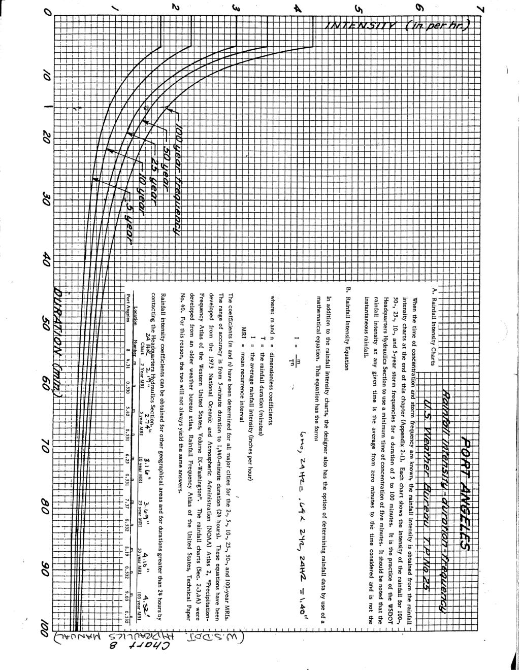
39
40
41 Construction Small Project SWPPP Stormwater Narrative Report WorkSheet A1 Small Project Stormwater Report Narrative and Plan Submittal HTE # Permit # Instructions: This is a template for a simplified Stormwater Report. This form or an equivalent must accompany your Building or Clearing and Grading Permit Application if the answer is Yes to each question below. If the project exceeds any threshold below, a Large Project Stormwater Plan is required and the project does not qualify for the simplified report template. Select yes or no for each question below. Answer yes if the statement accurately describes your project. Yes No Criteria This project disturbs less than 3/4 acre and is not part of a larger common plan of development. This project will create, add, or replace (in any combination) 2,000 square feet, but less than 5,000 square feet, of new plus replaced hard surface. OR Will disturb 7,000 square feet or greater. This project will not adversely impact a wetland, stream, water of the state, or change a natural drainage course. Note: Re-development projects with replaced hard surfaces greater than 5000 sq-ft in size may qualify for use of this Small Project Stormwater Report. See Urban Service Standards and Guidelines Chapter 5, Figure 5.2. Basic Project Information Parcel Tax Number(s): Project Name: Related Project File Number(s): Site Address: Total Lot Size: Total Proposed Area to be Disturbed (including stockpiles area): (sq ft) Total Proposed New Hard Surface Area: Total Proposed Replaced Hard Surface Area: (sq ft) Total Proposed Converted Previous Surface Area (Native vegetation to lawn or landscape): (sq ft) (sq ft) (sq ft) I have read and completed the Small Project Stormwater Report and the attached documents and know the information provided to be true and correct. Print Applicant Name: Applicant Signature: Date 1
42 Construction Small Project SWPPP Stormwater Narrative Report WorkSheet A1 Minimum Requirement # 1 : Preparation of Stormwater Site Plan Written Project Description: Calculate new or replace areas by surface type: Category A: Category B: Lawn or landscape areas: sq-ft Roof Area: sq-ft Category C: Other Hard Surface Areas: Driveway: sq-ft Patio: sq-ft Sidewalk: sq-ft Parking Lot: sq-ft Other: sq-ft Attach Stormwater Site Plan (Worksheet A2) Stormwater Site Plan (Worksheet A2) shall include the following: Scaled drawing with: slopes, lot lines, any public-right-of-way, location of each on-site stormwater management BMP s selected above and the areas served by them. Buildings, roads, parking lots, driveways, landscape features, areas of disturbed soils to be amended. This document must be suitable to serve as a recordable document that will be attached to the property deed for each lot that includes on-site BMPs. Identify design details and maintenance instructions for each on-site BMP, and attach them to this Small Project Stormwater Report. 2
43 Construction Small Project SWPPP Stormwater Narrative Report WorkSheet A1 Minimum Requirement # 2 : Construction Stormwater Pollution Prevention Attach completed Worksheet B: Construction Stormwater Pollution Prevention Plan and Narrative Minimum Requirement # 3 : Source Control of Pollution Provide a description of all known, available and reasonable source control BMP s that will be used on this project to prevent stormwater from coming into contact with pollutants. Additional BMP s are found in Volume 4 of the 2014 SWMMWW. Check the BMPs you will use: BMP S411 for Landscaping and Lawn/ Vegetation Management Operational practices for sites with landscaping BMP S412 for Parking and Storage of Vehicles. Public and commercial parking lots can be sources of suspended solids, metals, or toxic hydrocarbons such oils and greases. BMP S433 for Pools, Spas, Hot Tubs, Fountains Discharge from pools, hot tubs, and fountains can degrade ambient water quality. Routine maintenance activities generate a variety of wastes. Direct disposal of these waters to storm drain systems and waters of the state are not permitted without prior treatment and approval. Other BMP s found in Volume IV of SWMMWW applicable to project: No source control BMP s are applicable for this project. 3
44 Construction Small Project SWPPP Stormwater Narrative Report WorkSheet A1 Minimum Requirement # 4 : Preservation of Natural Drainage Systems Natural drainage patterns shall be maintained and discharges from the project site shall occur at the natural location, to the maximum extent practicable. All outfalls require energy dissipation. Choose the option below that best describes your project: This site has existing drainage systems or outfalls. These items are shown on the Small Project Drainage Plan (Worksheet A2). Include the following items on the Plan: Pipe invert elevations, slopes, cover Locations, Grades, and direction of flow in ditches and swales, culverts, and pipes Describe how these systems will be preserved: This site does not have any existing drainage systems or outfalls. Additional Comments: 4
45 Construction Small Project SWPPP Stormwater Narrative Report WorkSheet A1 Minimum Requirement # 5 : On-site Stormwater Management All projects meeting the thresholds for this Small Project Stormwater Report shall employ on-site stormwater management BMPs (See FactSheet A) to infiltrate, disperse, and retain stormwater runoff on-site to the extent feasible without causing flooding or erosion impacts. To determine the feasibility of on-site stormwater management BMPs use Worksheet C. A key feasibility criteria is the infiltration rates of your site soils. Choose the option below that best describes your project: This project results in less than 3000 sq-ft of new or replaced hard surface, project proponent shall complete the Infiltration Test Worksheet or determine soil infiltration rate by retaining professional services such as a: certified sewage designer, professional soil scientist, or professional engineer. What was the measured infiltration rate: Inch/hour This project results in 3000 sq-ft or more of new or replaced hard surfaces. The infiltration rates shall be determined by a: certified sewage designer, professional soil scientist, or professional engineer. What was the measured infiltration rate: On-site Stormwater Management BMP s are determined infeasible for a criteria other than infiltration rate or an existing soils report with measured infiltration rates is available for your location. Attach Worksheet C: Infeasibility Criteria Additional Comments: Inch/hour Using the City Stormwater Discharge Map, is your project located in the blue area which discharges directly or indirectly to a creek? Yes - Proceed to List #1 to select your on-site stormwater management BMPs. (Page 6) No - Proceed to List #3 to select your on-site stormwater management BMPs. (Page 7) 5
46 Construction Small Project SWPPP Stormwater Narrative Report WorkSheet A1 Minimum Requirement # 5 : On-site Stormwater Management (continued) List # 1 (Proceed with this page if you answered YES on page 5) For each category (A-C) select the first feasible item on the list below. Document your justification for each infeasible BMP using Worksheet C. Check One Option for Each Category Below: Category A: Lawn and Landscape Areas My project does not have Lawn or Landscape areas 1. Post-construction soil quality and depth Category B: Roofs My project does not have Roof areas 1. Full dispersion or downspout full infiltration 2. Rain Garden or bioretention 3. Downspout dispersion system 4. Perforated stub-out connections 5. Each item above is infeasible Describe why no Roof BMP is feasible and attached Worksheet C: Category C: Other Hard Surfaces My project does not have Other Hard Surface areas 1. Full dispersion 2. Permeable pavement, rain gardens, or bioretention 3. Sheet flow dispersion or concentrated flow dispersion 4. Each item above is infeasible Describe why no Other Hard Surface BMP is feasible and attached Worksheet C: 6
 For each category (A-C) select the first feasible item on the list below. Document your justification for each infeasible BMP using Worksheet C.")
47 Construction Small Project SWPPP Stormwater Narrative Report WorkSheet A1 Minimum Requirement # 5 : On-site Stormwater Management (continued) List # 3 (Proceed with this page if you answered NO on page 5) For each category (A-C) select the first feasible item on the list below. Document your justification for each infeasible BMP using Worksheet C. Check One Option for Each Category Below: Category A: Lawn and Landscape Areas My project does not have Lawn or Landscape areas 1. Post-construction soil quality and depth Category B: Roofs My project does not have Roof areas 1. Downspout full infiltration 2. Downspout dispersion system 3. Perforated stub-out connections 4. Each item above is infeasible Describe why no Roof BMP is feasible and attached Worksheet C: Category C: Other Hard Surfaces My project does not have Other Hard Surface areas 1. Sheet flow dispersion 2. Concentrated flow dispersion 4. Each item above is infeasible Describe why no Other Hard Surface BMP is feasible and attached Worksheet C: 7

48 Point Rd Eclipse Industrial Pkwy Ediz Hook Rd Vertical Datum = NAVD 88 Horizontal Datum = NAD 83/91 Plot date: December 2016 High Cedar Ln Evergreen Dr Estates Wy Gandalf Rd Whispering Firs Cir Mapleton Wy Edgewood Dr Lower Elwha Rd Gagnon Rd Saddle Club Rd US Hwy 101 Landfill site Dry Creek Rd Critchfield Rd Dry Creek Jakes Rd Harry Brown Rd Cameron Rd Reddick Rd McDonald St Sparrow Ln Cayanus Rd Hennessey Ln Melton Rd Tyler Rd Dutch Dr Milwaukee Dr Reyes St P St Butler St 19th St Jackson Alley Rd Cherry Ct Orchard Ave Walker St Delores Pl Edgewood Dr US Hwy 101 Fields Dr Apple Tree Ln Peach Pl Plum Ct Arbutus Ln O St Flores St Rolling Hills Dr 18th St Old Time Pl 10th St O St Woodside Cir Pacific Vista Fairchild Airport Rd Eclipse West Dr Heritage Ct Samara Dr Pl Samara Eclipse Industrial Pkwy Eva Cove Aurora Ct Dunker Dr Owen Ave Joshua St Devanny Ln Courtney Rd Arthur Ave Joshua St Cathleen St Hidden Cove Marie View St Ct Shirley 16th St Madeline St 15th St Clipper Cove Driftwood Pl 14th St L St Estes Ct Seabreeze Pl 12th St Seamount Dr Lauridsen Blvd Ross Ln Klahanie View Ln Winddancer Ln Benson Rd Hamilton Wy Juma Ct N St Cir Seaview Westview Dr Benson Rd Pollow Rd Bean Rd Spruce St Leo Ln Chickaree Ln Black Diamond Rd Harborview Dr 10th St Foxglove Ln Miller Creek Rd Alice Rd Evans Ave Fairmount Ave Gakin Rd M St L St 17th St 18th St 19th St Hazel St K St 16th St Spruce St Madrona St Glenwood St Fountain St Old Joe Rd Doyle Rd Hoare Rd Westridge Rd Hill St I St Doyle Rd C St Southridge Dr Diamond View Dr H St Newell Rd Old Black Diamond Rd G St 8th St Tumwater Creek 5th St Reservoir Rd F St Wellman Rd Fors Rd Hoare Rd Marine Dr E St Tumwater Truck Rt Nicholas Rd Black Diamond Rd D St Diamond Vista Dr C St Pine St Cutoff 11th St 12th St 13th St 14th St 15th St 16th St Lauridsen Blvd Edgewood Pl B St Motor Ave Dolan Ave Hancock Ave Fogarty Ave Forest Ave Columbus Ave Valley Creek Boathaven Dr A St 9th St 10th St Alderwood Cir Oak St Creekside Dr. Valley Creek Dr.Valley Crest Dr. Page Pl. Oak St Oak Ln 7th St Oakcrest Ave Oakcrest Lp Laurel St Page St. 6th St 5th St Apple Ln Galaxy Pl 4th St Valley St Tumwater St 3rd St Lincoln St Viewcrest Ave Mill Ck Ct City Lights Pl Hawthorne Pl Dogwood Pl Juniper Ln Old Mill Rd Cedar St Orcas Ave Lopez Ave Whidby Ave Vashon Ave Grants View St Pine St Peabody St Ahlvers Rd Crabapple Pl Maple St Maple St Hillcrest Dr Rhodes Rd Scribner Rd This map is not intended to be used as a legal description. This map/drawing is produced by the City of Port Angeles for its own use and purposes. Any other use of this map/drawing shall not be the responsibility of the City. S:\ARCINFO\GWater\StormwaterDischarge.mxd Mill Creek Park Knoll D r Coyote Run Ln Port Angeles Harbor Vine St Albert St Cherry St Lauridsen Blvd Regent St Vista View Dr Hillcrest Dr Meadow Cir Thistle St Upland Ln Hill Cir Rose St Eunice St Peabody Creek Railroad Ave Park Ave Canyonedge Dr Canyon Cir Oak St Eunice St Hurricane Ridge Rd Laurel St 8th St Francis St Lincoln St 5th St Race St Hurricane Ridge Rd Burch Ave Burch St Church St Solar Ln Mt Angeles Rd Eckard Pl Benjamin Ave Willow Ave McGill Ave Glenbrook Cir Chase St Nygren Pl Peabody St 1st St Bryson Ave Franklin Ln Scrivner Rd Key Rd Front St Eckard Ave Vine St Mt Angeles Rd Albert St Georgiana St Highland Ave Grant Ave Olympus Ave Center St Homestead Ave McDougal St Washington St Craig Ave Eckard Ave Morning Ct Eunice St Porter St Francis St Campbell Ave Forest Trail Rook Dr Bent Cedars Wy White Creek Race St Caroline St 6th St 7th St 8th St Wabash Ave Washington St Eckard Ave Tiller Rd Doss Rd Chambers St Columbia St Liberty St Scrivner Rd Water St Ennis St Lambert Ln Currier Ct Mountain Terrace Wy Jones St Melody Cir Alder St 3rd St 6th St 2nd St 5th St 4th St Elizabeth Pl Christm an Pl Wolcott St Nancy Ln Melody Ln Woodhaven Ln Golf Course Rd Harborcrest Pl Penn St Golf Course Rd Tara Ln Tara Ln Old Nelson Rd Keller Dr US Hwy 101 Lindberg Rd Village Cir Maddock Rd Village Pl Ennis Creek Weiler Rd Beech St Bourchier St Ennis Creek Rd Delguzzi Dr Fernwood Ln Brown Rd Baker St Pioneer Rd Mcblair Ln 3rd Ave 4th Ave 5th Ave 6th Ave 7th Ave Brown Rd Arnette Rd Mariah Winds Wy Billy Smith Rd Gales St Jensen Rd Hughes Rd Legend 2,400 Feet Stormwater Discharge Map Gravel/Dirt streets City arterial City side street County road River and creek Harbor County jurisdiction Determine Receiving Water: Creek (List #1) Direct Discharge (List #3)
49 DRAINAGE PLAN REQUIREMENTS A B C D E F G CITY OF PORT ANGELES STORMWATER SITE PLAN (SWSP) WORKSHEET A2
50

: Scarify the top 4 inches of subsoil Rip in the first lift of topsoil Rip site soils 12 inches deep")
51 Post-Construction Soil Management Worksheet D Benefits of Healthy Soils Reduced need for irrigation, fertilizers, and pesticides Decreased stormwater runoff Decreased erosion Improved plant health Marketable buildings and landscapes Before 5 Step Implementation Process After Step 1 Retain and protect native vegetation and soil Identify areas of the site that will not be disturbed during construction (cleared, graded, or driven on). Fence those areas to prevent impacts during construction. If neither soils nor vegetation are disturbed, these areas do not require amendment. Step 2 Loosen compacted subsoil, if needed In disturbed areas (compacted by construction traffic): Scarify the top 4 inches of subsoil Rip in the first lift of topsoil Rip site soils 12 inches deep before tilling compost in to an 8-inch depth Step 3 Restore soils that are disturbed during construction Three options to restore disturbed soils include: Option 1: Till compost (1.75 inches for turf areas; 3 inches for planting beds) into existing soil, or Option 2: Stockpile and reuse existing topsoil (amend if needed to meet 5% organic matter content for turf areas; 10% organic matter content for planting beds), soil test requied for this option, or Option 3: Import 6 inches of compost-amended topsoil (25% compost for turf areas; 40% compost) and scarify or till into existing soil in two 3-inch lifts 1
 Step 4 Add mulch to planting beds Compost options require tilling to a depth of 8 Spread mulch (coarse bark or wood chips) in the spring or fall (after planting) to control weeds, reduce the need")

52 Worksheet D Post-Construction Soil Management 5 Step Implementation Process (cont.) Step 4 Add mulch to planting beds Compost options require tilling to a depth of 8 Spread mulch (coarse bark or wood chips) in the spring or fall (after planting) to control weeds, reduce the need for irrigation, and prevent erosion. Apply 1 to 2 inches of mulch on planting beds and around shallow-rooted annuals. Apply 2 to 4 inches of mulch around trees and woody perennials, but make sure to keep mulch 1 inch away from tree trunks. Step 5 Protect restored soils from erosion and re-compaction Prevent runoff from roads or open slopes onto amended soil areas. Compost blankets are an approved erosion control BMP that can be used during construction and then tilled into the existing soil at the end of the construction process prior to planting. Once soils have been amended, vehicle traffic should be prohibited to prevent re-compaction from occurring. Exemptions The following portions of the project area are exempt from soil amendment requirements: Areas covered by an impervious surface, or Areas incorporated into a drainage facility, or Structural fill or engineered slopes On till slopes greater than 33% Turf Stockpile and reuse existing topsoil if it meets the organic matter content requirements Planting bed Native, undisturbed soil 1-2 of mulch 1.75 of compost or 6 of compost-amended topsoil tilled in to an 8 depth 3 of compost or 6 of compost-amended topsoil tilled in to an 8 depth 2
53 Post-Construction Soil Management Worksheet D Worksheet Project Information Page # of pages Calculate the quantities needed for the entire site based on all of the areas identified on the Site Plan and the calculations on the following page(s) Project file number: Section: Township: Range: Property Tax Account Number(s): Project Name: Related Project File Number(s): Site Address: Attachments Required (Check off required items that are attached) Site Plan showing, to scale: Areas of undisturbed native vegetation (no amendment required) New planting beds (amendment required) New turf areas (amendment required) Type of soil improvement proposed for each area Soil test results (required if proposing custom amendment rates) Product test results for proposed amendments Total Amendment / Topsoil / Mulch for All Areas (Calculate the quantities needed for the entire site based on all of the areas identified on the Site Plan and the calculations on the following page(s) Product Total Quantity (CY) Test Results Product #1: Garden Glory Compost (Port Angeles Landfill Facility [PALF]) Product #2: Product #3: CY CY CY % organic matter C:N ratio Stable? yes no % organic matter C:N ratio Stable? yes no % organic matter C:N ratio Stable? yes no 3
54 Post-Construction Soil Management Worksheet D For each identified area on your site plan, provide the following information (Use additional sheets if necessary): Area # (should match identified Area # on Site Plan) Planting type: Turf Undisturbed native vegetation Planting Beds Other: Pre-Approved Amendment Method Amend with compost Stockpile and amend Turf: SF x 5.4 CY 1,000 SF = CY Planting beds: SF x 9.3 CY 1,000 SF= CY Total Quantity = CY Scarification depth: 8 inches Turf: SF x 5.4 CY 1,000 SF = CY Planting beds: SF x 9.3 CY 1,000 SF= CY Total Quantity = CY Scarification depth: 8 inches Product: Garden Glory Compost (PALF) Other: Product: Garden Glory Compost (PALF) Other: Topsoil import Custom Amendment Amend with compost Turf: SF x 18.6 CY 1,000 SF = CY Planting beds: SF x 18.6CY 1,000 SF= CY Total Quantity = CY Scarification depth: 6 inches Attach information on bulk density, percent organic matter, moisture content, C:N ratio, and heavy metals analysis to support custom amendment rate and scarification depth. Total Quantity = Scarification depth: CY inches Product: Garden Glory Compost (PALF) Other: Product: Garden Glory Compost (PALF) Other: Mulch Stockpile and amend Amend with compost Stockpile and amend Topsoil import Attach information on bulk density, percent organic matter, moisture content, C:N ratio, and heavy metals analysis to support custom amendment rate and scarification depth. Total Quantity = Scarification depth: CY inches Planting beds: SF x 12.4 CY 1,000 SF= CY Total Quantity = CY Planting beds: SF x 12.4 CY 1,000 SF= CY Total Quantity = CY Planting beds: SF x 12.4 CY 1,000 SF= CY Total Quantity = CY Product: Garden Glory Compost (PALF) Other: Product: Product: Product: 4

55 PORI STANDARD DETAIL GRATE AND HOOD TO HAW "DRAINS To CREEKS" or 9II,I/LAR B A+_ I AS APPROWD BY THE CITY ENGINEER CAST INTO THEM. GRATES AND HOODS ro HAW BtruMtNOUs CoAnNG B EXPANSlON JOINT *H 8d B H H H B B Ë$ JOINT cðncrllé VANED GRATE* J'-O' A+-J J'-0" MATCH GUNER LIP OR EXßNNG PAWMENT ELEVANON 1'O' I,IIN. FROTI FACE OF CURE (ryp.) * USE BI-DIRECNONAL GRATE AT SACS MATCH EXISflNG PAWMENT ELEVAT ONS AT GRA E EDCE 0.1' 4 Ì ADJUSTlNC AS NECESSARY EXPANSION JOINT s v t{ d ë s PVC PIPE lnstallanon 6" MtN. EXPANSION JOINT NOTES: I, OIL SEPARATOR "T" REQUIRED AT OUNET UNLESS O\HERMSE APPROWD BY dty ENGINEER. I,IANHOLE ADAPTOR USE CATCH BASIN TYPE 1 BASE FOR 6" PIPE. USE TYPE 2 BASE FOR 8" AND LARGER PIPE. SECTION B_B 2, CONCRETE CLASS JOOO MATCH EXISTING PAWMENT ELEVAT ON J. CATCH BASIN BASE ro BE SET LEWL. CRATE FRAME TO 8E SHITIIIED TO MATCH LONGIruDINAL SLOPE. o.02"/fr. SLOPE GRATE SLOPE A ö g) OLYMPIC FOUNDRY FRAIûE sm 52-A W\H J/6" NON-SK D DIAIúOND PAT ERN ON TOP SURFACE. ADJUST HOOD TO MATCH CURE HE\GHT G" MtN. OPENTNG) \ 4 APPROVED BY CITY ENGINEER : SECTION A-A NOT TO SCALE ALL WORK AND MA\ERIAL TO BE IN ACCORDANCE MTH THE CURRENT.STANDARD WASHINGTON STATE DEPAR'THENT OF'IRANSPORTANON SPECIFICANONS FOR ROAD, BRTDGE, AND MUNICIPAL CONS'IRUCNON' FILE NAME: CURB NLETDWG DATE : REVISED ð/ræ6- t//7 CAU FOR FORU INSPECNON 8Y CI Y 24 HOURS PRIOR IO PWRINA CONCREIE. CALL FOR INSPECNOìI EY CI Y 24 HOURS PRIR TO AACKFILL. THROUGH CURB INLET I N STALLATI ON

56 PORT STANDARD DETAIL SLOTTED TRAFF/C GRATE A GRATE TO HAVE "DRAINS TO CREEKS'' OR SlMILAR AS APPROVED BY THE C/TY ENG.NEER CAST lnto /T. ALL CAST.NGS SHALL HAVE BITUM/NOUS COATING. A n E ü E OUTLET P/PE SHALL EXTEND TO THE SHOULDER OF THE TEE. A 4 A s (o À 4 A t-u ù ùs s PVC PIPE lnstallanon 6" M/N. AlANHOLE ADAPTOR s il PVC TEE (stur DlAMETER AS OUTLET P/PE,) SECTION A_A NOT TO SCALE ALL WORK AND MA ERIAL TO BE IN ACCORDANCE WTH IHE CURRENT WASHINGTON STAIE DEPAR\MENT OF TRANSPORTANON.STANDARD SPECIFrcANONS FOR ROAD, BRIDGE, AND MIJNICIPAL CONSTRUCNON, CAU FOR INSPECNON BY CITY 24 HOURS PRIOR TO BACKFILL. APPROVED BY CITY ENGINEER FILE NAME: PARKINGLOTCB.DWG DATE : REVISED : 8?4æ6- tl/7 PARKING LOT CATCH BASIN

57 PORT STANDARD DTTAIL ASPHALT CONCREIE PAVE IËNT CLASS B, PCC PAWMENT (HIGH EARLY), OR PERMEABLE PAVEMENT. IIATCH EXISNNG PAWIENT TYPE AND DEPTH. SEE NOTE 14. 7l I' FOR ARTER AL STREETS FOR ACCESS STREETS/ALLEYS cuts 5HALL BE SArvw. SEE NOTE 13. C.D BACKF LL OR. PERMEABLE BALLAST FOR PERMEABLE PAWMENT 6" MAX. BEDDINC 4" NOT TO SCALE C.D. BACKF.LL SPEC.FICANONS NOTES LBS. OF 0.J75 IN. AGCRECATE 600 LBS. OF STANDARD CONCRETE SAND 94 LB'. OF PORTLAND CEMENT APPROX. 14 GAL. OF WA'IER THE AIúOUNT OF WATER IS A CR TICAL FACTOR TO SET UP MfE AND SHOULD BE ADDED AT HE S TE 1. ACP PATCH SHALL BE ROLLED AND NOT VIBRAIED. 2 0 BE USED FOR ALL PAWD STREETS AND ALLEYS. BACKHLL LOCAflON TO I'_0,' BEHIND CURB OR EDGE OF PAWNG UNLESS OTHERIYISE APPROWD IN ADVANCE BY CITY ENGINEER. J, WHERE CONCRETE PAWMENT JO NT IS LESS THAN 4'-0" FROM SAWCUtr HE PAVEMENT SHALL BE REIIOWD ro rhar JotNr. 4, \EMPORARY PATCHING WTH ASPHALT OR PLACEI'IENT OF STEEL PLATES ß REQUIRED WHEN TRAFFIC IuILL CROSS CDF FOR MORE THAN 24 HOURS WITHOUT PERMANENT RESTORANON. STEEL PLATES SHALL HAW COLD PATCH WEDGES ON TRAFF C EDGES. ALL WORK AND MAIERIAL TO BE IN ACCORDANCE WTH HE CURRENT WASHINGTON STATE DEPARruENT OF 'IRANSPORTANON 'STANDARD SPECIFrcANONS FOR ROAO, BRIDCE, AND MUNICIPAL CONS\RUCNON" CALL FOR INSPECNON BY CI Y 24 HOURS PRIOR TO PLAANO CDF BACKNLL. APPROVED BY CITY ENGINEER FILE NAME: CDF.DWC DATE : REVISED J/5r46- t//7 CONTROLLED DENSITY FILL (cdf)
 GEOTEXTILE (/F,PEC.FIED BY tnctneer) WATER QUALITY TREATMENT COURSE (tr 6,, MIN.")
58 PORÌ STANDARD DETAIL PAVERS PERMEABLE PAVER FACILIry VARIES PO ROUS ASPHALT OR PERVIOUS CONCRETE FACILIry POROUS ASPHALT OR PERV OUS CONCRETE WEAR4NG COURSE LEVELING COURSE (PER MANUFACTURER) VAR4ES LEVELING COURSE, OPT ONAL STORAGE RESERVOIR* 6" MlN. STORAGE RESERVOIR* GEOTEXT4LE (/F SPEC\1ED BY ENGINEER) GEOTEXTILE (/F,PEC.FIED BY tnctneer) WATER QUALITY TREATMENT COURSE (tr 6,, MIN. WATER QUALITY TREATMENT COURSE (/F REOUIRED) SUBGRADE * STORAGE RESERVO4R MUST BE LA.D PART ALLY OR COMPLETELY BELOW SURROUND4NG FIN SH GRADE. SUBGRADE MIN. I,OR J,ABOVE SEASONAL HlGH GROUNDWATER ELEVAT ON AND H YD RA UL/ CA L L Y_ RES TRI C N VE MATERUL TE î. OVERFLOW AND LATERAL SUBSURFACE IMPERT EABLE BERMS NOT SHOWN. APPROVED BY CITY ENGINEER FILE NAME: PERM PAVE SECTS DAÏE : REVISED t//7 PERMEABLE PAVEMENT SECTIONS

59 PORI STANDARD DETAIL 2%- FINISHED GRADE PER PLAN LANE TRAVEL GEOTEXTILE EACH SIDE, TYP SEE NOTE 1. PERMEABLE PAVEMENT SIDEWALK ADJACENT TO CURB SWALE OR DITCH 2% FINISHED GRADE PER PLAN ORETENTION SOIL GEOTEXTILE EACH SIDE, TYP SEE NOTE 1. PERMEABLE PAVEMENT SIDEWAL ADJACENT TO SWALE OR DITCH NOTES 1. DRAPE EXCESS GEOTEXTILE OVER FINISHED PERMEABLE PAVEMENT DURIING CONSTRUCTION TO PROTECT FINISHED PERMEABLE PAVEMNT SURFACE. APPROVED BY CITY ENGINEER FILE NAME: PERMEABLE WALK DATE : REVISED 1//7 PERMEABLE SIDEWALK

60 PORI STANDARD DETAIL TOP CELL WIDTH PONDING AREA WIDTH BOTTOM CELL WIDTH 12" MlN. (AVERAGE) TYPICAL PRIVATE PROPERTY OVERFLOW 6'' MAX. AVERAGE PONDING DEPTH FREEBOARD 2_3'' DEPTH ARBORIST WOODCHIP MULCH TO APPROVED POINT OF DISCHARGE BOTTOM OF FACILITY. SCARIry SUBGRADE 4'' MIN. BEFORE BIORETENTION SOIL INSTALLATION MIN. 1' OR 3' ABOVE SEASONAL HIGH GROUNDWATER ELEVATION AND HYDRAULICALLY_RESTRICTIVE MATERIAL 2_5'' DEPTH OF COMPOSTED MATERIAL IN PONDING AREA COMPOST AMENDED OR 12'' MIN. BIORTTENTION SOIL RAIN GARDTN SECTION APPROVED BY CITY ENGINEER FILE NAME: RAIN GARDEN DATE : REVISED r/5/06 RAIN GARDEN
 TYPICAL PRIVATE PROPERry OVERFLOW FREEBOARD 2_3'' DEPTH ARBORIST WOODCHIP MULCH _3'' DEPTH OF COMPOSTED MATERIAL IN PONDING AREA (o TO APPROVED POINT OF DISCHARGE MIN.")
61 PORT STANDARD DETAIL 12" I'tlAX. AVERAGE PONDING DEPTH TOP CELL WIDTH PONDING AREA WIDTH BOTTOM CELL WIDTH 1B" MIN. (AVERAG r) TYPICAL PRIVATE PROPERry OVERFLOW FREEBOARD 2_3'' DEPTH ARBORIST WOODCHIP MULCH _3'' DEPTH OF COMPOSTED MATERIAL IN PONDING AREA (o TO APPROVED POINT OF DISCHARGE MIN. 1, OR 3' ABOVE SEASONAL HIGH GROUNDWATER ELEVATION AND HYDRAULICALLY- RESTRICTIVE MATERIAL M IN. M IN. BIORETENTION SOIL 18" MtN TYPE 26 MNRL AGG SLOTÏED UNDERDRAIN PIPE 1 WHEN FACrLrry rs USED ro MEil FLOW CONTROL AND/OR ON-S TE STORMWATER MANAGEMENT REQUIREMENTS AND THE FACILITY DRAINS TO A RETENTION OR DETENTION FACILIry, THE TYPE 26 MINERAL AGGREGATE UNDER THE UNDERDRAIN PIPE MUST BE WIDENED TO EXTEND ACROSS THE ENTIRE CELL BOTÏOM. INFILTRATING BIORTTTNTION WITH SLOPTD SIDES AND UNDERDRAIN SECTION APPROVED BY CITY ENGINEER FILE NAME: B/ORETEN1ON DATE : REVISED 1////7 BIORETENTION
62 PORI STANDARD DETAIL O\ RFLOW FRAME & BSEHIVE GRATE, OLYMPIC FOUNÐRY TYPE SM6O & SM6OBH, OR APPROVEÐ EQ TYP STREAMSED COBBTE (1--4) PONDING CELL BO TOM 3,'DEPTH OF ; COMPOSTED MATERIAL øt CULV (DIP), TYP BIORilENTION SOIL 3" DEPIH t l OODCHlP UULCH, COARSE 3" DTPTH OF COMPOSTED MATERIAL sorl * Q8" MINIMUM. DTIËRMINEÐ ÐI ËNGINEER JUNCTION BOX OR CATCH BASIN L APPROVED BY CITY ENGINEER FILE NAME: OWRFLOW DATE : REVISED t/r/7 OVTRFLOW STRUCTURT
63 PORI STANDARD DITAIL APPROVED BY CITY ENGINEER FILE NAME: CUB CUT INLET DATE : REVISED /,n,n7 CURB CUT INLET
64 PORT STANDARD DETAIL 1 v I \' 2" DROP FROM GUTTER ÏO TOREBAY (TYP) THICKENED CURB AND OUTTFR VARIES EXISTING CURB B.A - / PLÂNTINç5 \t ÕUTLET NOTCH à A EXISTIN6 CURB APPROVED BY CITY ENGINEER FILE NAME: CUB /NLET W-DROP DATE : REVISED : 1/L/î7 CURB INLTT WITH DROP
65 PoRr STANDARD DETAIL \ t, a o ) I or rnee 3' DIq WATERING RING 1r1 MAX CURB & GUTTER STD PLAN 41OB 3, DEPTH MULCH, COARSE BIORETENÏON SOIL, COMPACTED ro 90% DENSITY BIORETEN]]ON SO]L 3, DEPTH OF COMPOSTED MATER1AL IN PONDING AREA APPROVED BY CITY ENGINEER FILE NAME: TREE ln SWALE DATE : REVISED : t//17 TRET PLANTING WITHIN BiORTTENT ON SWALT
, OR AS DETERMINED BY THE CITY 8\" 12\" SUBSOIL SCARIFIED 4' BELOW COMPOST AMENDED LAYER (12\" BELOW SO L SURFACE), OR AS DilERMINED BY THE CITY CROSS STCTION OF")
66 PORI STANDARD DETAIL 2''_4'' MULCH 0" GRASS: SEED OR SOD 3'' OF COMPOST INCORPORATED INTO SOIL TO 8'' DEPTH 1 3/4" OF COMPOST INCORPORATED INTO SOIL TO 8" DEPTH SUBSOIL SCARIFIED 4,, BELOW COMPOST AMENDED LAYER (12" BELOW SO L SURFACE), OR AS DETERMINED BY THE CITY 8" 12" SUBSOIL SCARIFIED 4' BELOW COMPOST AMENDED LAYER (12" BELOW SO L SURFACE), OR AS DilERMINED BY THE CITY CROSS STCTION OF SOIL AMTNDMTNT APPROVED BY CITY ENGINEER FILE NAME: SO L AtulEND S CT DATE : REVISED /////7 SOIL AMENDMENT SECTI ON S
Chapter 4 - Preparation of Stormwater Site Plans
 Chapter 4 - Preparation of Stormwater Site Plans The Stormwater Site Plan is the comprehensive report containing all of the technical information and analysis necessary for the City to evaluate a proposed
New Development Stormwater Guidelines
 New Development Stormwater Guidelines CITY OF MOUNTLAKE TERRACE Table of Contents Introduction... 2 Ecology s Minimum Requirements for stormwater management... 2 Description of the 9 Minimum Requirements...
CHAPTER 9 STORM DRAINAGE. Minimum Requirements for New Development and Redevelopment
 CHAPTER 9 STORM DRAINAGE 9.01 General The standards established by this chapter are intended to represent the minimum standards for the design and construction of storm drainage facilities. 9.02 Design
Appendix I. Checklists
 Appendix I Checklists Town of Greenwich Drainage Manual Department of Public Works - Engineering Division Town Hall - 101 Field Point Road, Greenwich, CT 06836-2540 Phone 203-622-7767 - Fax 203-622-7747
STORMWATER SITE PLAN INSTRUCTIONS AND SUBMITTAL TEMPLATE Medium and Large Projects
 DEPARTMENT OF COMMUNITY DEVELOPMENT 621 Sheridan Street, Port Townsend, WA 98368 Tel: 360.379.4450 Fax: 360.379.4451 Web: www.co.jefferson.wa.us/communitydevelopment E-mail: dcd@co.jefferson.wa.us STORMWATER
SECTION 1 CLEARING /GRADING PERMIT APPLICATION:
 PLEASE REFER TO THE CLEARING & GRADING PERMIT CHECKLIST BELOW FOR SUBMITTAL REQUIREMENTS. SECTION 1 CLEARING /GRADING PERMIT APPLICATION: PROJECT ADDRESS (Street, Suite #): Parcel(s) #: Total Site Area
Introduction Post Construction Stormwater Management Performance Requirements
 Introduction Post Construction Stormwater Management Performance Requirements The primary objective of these Post Construction Stormwater Management Performance Requirements is to minimize the downstream
STORMWATER PERMIT SUBMITTAL REQUIREMENTS
 STORMWATER PERMIT SUBMITTAL REQUIREMENTS Most development within the City of Bellingham that involves disruption of soils, or construction of buildings, streets, parking lots, etc. requires a Stormwater
Introduction Post-Construction Stormwater Management Performance Requirements
 EZ MANUAL Introduction Post-Construction Stormwater Management Performance Requirements The primary objective of these Post-Construction Stormwater Management Performance Requirements is to minimize the
Directors Rules for Seattle Municipal Code, Chapters Stormwater Code
 Directors Rules for Seattle Municipal Code, Chapters 22.800 22.808 Stormwater Code Requirements for Green Stormwater Infrastructure to the Maximum Extent Feasible for Single-Family Residential and Parcel-Based
Drainage Control Plans
 2016 Drainage Design and Erosion Control Manual - Guide Sheet 1C Drainage Control Plans A Drainage Control Plan is the comprehensive submittal package containing all of the technical information, analysis,
Draft Rhode Island Stormwater Design and Installation Standards Manual
 Draft Rhode Island Stormwater Design and Installation Standards Manual Summary The May 2009 Public Review Draft version of the RI Stormwater Design and Installation Standards Manual consists of approximately
2.1.4 Roof Downspout Rain Gardens
 2008 SWMM, 2010 Revision City of Tacoma 2.1.4 Roof Downspout Rain Gardens Purpose and Definition Bioretention areas are shallow stormwater retention facilities designed to mimic forested systems by controlling
3. Are there any projects exempt from the definition of Regulated Projects?
 STORMWATER REQUIREMENTS: OVERVIEW OF PROVISION C.3 Background: On October 14, 2009, the Regional Water Quality Control Board, San Francisco Bay Region, issued a municipal regional stormwater permit (MRP)
Huntington Stormwater Utility
 Huntington Stormwater Utility Stormwater Management & Sediment and Erosion Control Requirements for Construction Sites Authorized by Huntington City Code Articles: 971, 970, 930, 935, 955, Revised April
APPENDIX A SIMPLIFIED APPROACH TO STORMWATER MANAGEMENT FOR SMALL PROJECTS. In West Sadsbury Township, Chester County, Pennsylvania
 APPENDIX A SIMPLIFIED APPROACH TO STORMWATER MANAGEMENT FOR SMALL PROJECTS In West Sadsbury Township, Chester County, Pennsylvania TABLE OF CONTENTS I. Introduction 3 II. Importance of Stormwater Management
4. CONCEPT PLAN DEVELOPMENT
 4. CONCEPT PLAN DEVELOPMENT Concept Plan Step 1: Identify Site Constraints and Opportunities Review the existing site to identify constraints and opportunities for GI Practices to meet the RRv. Constraints
STORMWATER MANAGEMENT CODES ANALYSIS RICHLAND COUNTY, SC SITE PLANNING ROUNDTABLE
 STORMWATER MANAGEMENT CODES ANALYSIS RICHLAND COUNTY, SC SITE PLANNING ROUNDTABLE Codes analyses for each subcommittee were completed to assist participants of the Richland County Site Planning Roundtable.
Article 20 Stormwater Management
 Article 20 Section 20.01 Intent Article 20 The purpose of this Article is to protect the health, safety, and general welfare of the citizens by requiring compliance with accepted standards and practices
5. LOW IMPACT DEVELOPMENT DESIGN STANDARDS
 5. LOW IMPACT DEVELOPMENT DESIGN STANDARDS Low Impact Development (LID) requires a shift in stormwater management away from conveying runoff to a small number of downstream points through hydraulically
Title 11 Streets and Sidewalks
 Chapter 11.01 - Definitions Title 11 Streets and Sidewalks Low Impact Development (LID) - A stormwater and land use management strategy that strives to mimic predisturbance hydrologic processes of infiltration,
WHATCOM COUNTY LID CODE INTEGRATION PROJECT WCC (DEFINITIONS)
") Chapter 20.97 DEFINITIONS Sections: 20.97.029 Best management practice (BMP). 20.97.171.1 Hard surface. 20.97.171.1 2 Hazard tree. 20.97.187 Impervious surface. 20.97.194.1 Land disturbing activity. 20.97.220.1
Chapter 20.97 DEFINITIONS Sections: 20.97.029 Best management practice (BMP). 20.97.171.1 Hard surface. 20.97.171.1 2 Hazard tree. 20.97.187 Impervious surface. 20.97.194.1 Land disturbing activity. 20.97.220.1
County of Prince Edward. Stormwater Management Plan. Agreement in lieu of a Stormwater Management Plan
 County of Prince Edward Stormwater Management Program Date: E-Permitting Number: This stormwater management plan (Agreement) is hereby submitted by the Owner to specify the methods that will be implemented
DEPARTMENT OF PUBLIC WORKS & UTILITIES
 CITY OF PORT ANGELES DEPARTMENT OF PUBLIC WORKS & UTILITIES URBAN SERVICES STANDARDS AND GUIDELINES January 2017 Craig Fulton, P.E., Director TABLE OF CONTENTS "URBAN SERVICES STANDARDS AND GUIDELINES"
ORDINANCE NUMBER DRAFT. An ordinance amending Title 12 Environmental Protection of the Los Angeles County
 ORDINANCE NUMBER DRAFT 1 1 1 1 1 1 0 1 An ordinance amending Title 1 Environmental Protection of the Los Angeles County Code, establishing Low Impact Development standards. The Board of Supervisors of
Public Works Department 104 W. Magnolia Street, Suite 109 Bellingham, WA (360)
") Public Works Department 104 W. Magnolia Street, Suite 109 Bellingham, WA 98225 (360) 778-7900 STORMWATER PERMIT SUBMITTAL REQUIREMENTS Most development within the City of Bellingham that involves disruption
Public Works Department 104 W. Magnolia Street, Suite 109 Bellingham, WA 98225 (360) 778-7900 STORMWATER PERMIT SUBMITTAL REQUIREMENTS Most development within the City of Bellingham that involves disruption
Project Applicant Checklist for NPDES Permit Requirements SAN MATEO COUNTYWIDE STORMWATER POLLUTION PREVENTION PROGRAM
 Project Applicant Checklist for NPDES Permit Requirements SAN MATEO COUNTYWIDE STORMWATER POLLUTION PREVENTION PROGRAM I. PROJECT DATA Project Name Bay Meadows Development Phase II Project Address 2600
Slow it, Spread it, Sink it using Green Stormwater Infrastructure
 Milly Archer Water Resources Coordinator Becky Tharp Green Infrastructure Collaborative Slow it, Spread it, Sink it using Green Stormwater Infrastructure Overview Defining LID and GSI Hydrology and impacts
Post-Construction Stormwater Management Checklist* (5,000 SF or Greater)
") Applicability: Required for projects that create and/or replace 5,000 square feet or greater of impervious surface (i.e. asphalt roads, concrete structures, building area, sidewalks, etc.). Impervious
Applicability: Required for projects that create and/or replace 5,000 square feet or greater of impervious surface (i.e. asphalt roads, concrete structures, building area, sidewalks, etc.). Impervious
When planning stormwater management facilities, the following principles shall be applied where possible.
 2.0 Principles When planning stormwater management facilities, the following principles shall be applied where possible. 2.0.1 Drainage is a regional phenomenon that does not respect the boundaries between
CHECKLIST FOR PHASE II DRAINAGE REPORT
 I. COVER SHEET CHECKLIST FOR PHASE II DRAINAGE REPORT A. Name of Project B. Address C. Owner D. Developer E. Engineer F. Submittal date and revision dates as applicable II. GENERAL LOCATION AND DESCRIPTION
Post - Construction Hydromodification Development Requirements
 Condensed Version - Interim Low Impact Development / Hydromodification Guidelines, City of Lompoc 1 Post - Construction Hydromodification Development Requirements I. PURPOSE A. The purpose of these requirements
2/10/2017 INSTRUCTORS WESTERN WASHINGTON. REBECCA DUGOPOLSKI, PE Senior Engineer Key project experience: Stormwater monitoring,
 1 Statewide LID INTERMEDIATE LID TOPICS: NPDES PHASE I Training Program AND PHASE II PERMIT REQUIREMENTS WESTERN WASHINGTON 2 INSTRUCTORS REBECCA DUGOPOLSKI, PE Senior Engineer Key project experience:
Homeowners Guide to Stormwater BMP Maintenance
 Homeowners Guide to Stormwater BMP Maintenance What You Need to Know to Take Care of Your Property Rain Barrel Dry Well Rain Garden Pervious Asphalt Porous Pavers City of El Monte Stormwater BMP Management
STORMWATER GREEN INFRASTRUCTURE AND PLANNING/ZONING BOARDS
 STORMWATER GREEN INFRASTRUCTURE AND PLANNING/ZONING BOARDS Source: Center for Watershed Protection, 2007 Southern Tier Central Regional Planning & Development Board Chemung County Stormwater Team OUTLINE
Example Stormwater Control Plan For a Residential Subdivision Project. Whispering Pines Lane Anytown, USA. February 21, 2018
 Example Stormwater Control Plan For a Residential Subdivision Project Whispering Pines Lane Anytown, USA February 21, 2018 XYZ Corporation Jane Jones, 925-555-1212 This example prepared by Dan Cloak Environmental
Appendices: Glossary. General Terms. Specific Terms. Low Impact Development Approaches Handbook
 67 67 General Terms Specific Terms 66 Low Impact Development Approaches Handbook The vocabulary of low impact development is evolving, and many terms are used interchangeably and to describe the same or
Stormwater Management Techniques WMPF LAND USE TRAINING INSTITUTE MARCH 14, 2018
 Stormwater Management Techniques WMPF LAND USE TRAINING INSTITUTE MARCH 14, 2018 Potential Impacts of New Development Urban development can significantly increase stormwater runoff Water quality considerations
Community LID Workgroup Issue Paper #6
 Community LID Workgroup Issue Paper #6 Topic: Hard and Impervious Surface Coverage Limits Objective: Minimize the amount of hard and impervious surfaces in developments to allow more stormwater to infiltrate
DRAFT DESIGN CRITERIA STORMWATER TREATMENT STANDARDS CITY OF OVERLAND PARK
 DRAFT DESIGN CRITERIA STORMWATER TREATMENT STANDARDS CITY OF OVERLAND PARK A. Authority As set forth in the Overland Park Municipal Code (OPMC), Chapter 16.210, the Director of Planning and Development
2008 SWMM, 2010 Revision City of Tacoma
 2008 SWMM, 2010 Revision City of Tacoma 2.2.3.1 BMP L630 Rain Gardens Purpose and Definition Bioretention areas are shallow stormwater retention facilities designed to mimic forested systems by controlling
NON-PRIORITY PROJECT WATER QUALITY PLAN (NPP)
") NON-PRIORITY PROJECT WATER QUALITY PLAN (NPP) For: (Insert Project Name) (Site Address or Tract/Lot Number) Prepared for: (Insert Owner/Developer Name) (Insert Address) (Insert City, State, ZIP) (Insert
NON-PRIORITY PROJECT WATER QUALITY PLAN (NPP) For: (Insert Project Name) (Site Address or Tract/Lot Number) Prepared for: (Insert Owner/Developer Name) (Insert Address) (Insert City, State, ZIP) (Insert
GENERAL ASSEMBLY OF NORTH CAROLINA SESSION 2007 SESSION LAW SENATE BILL 1967
 GENERAL ASSEMBLY OF NORTH CAROLINA SESSION 2007 SESSION LAW 2008-211 SENATE BILL 1967 AN ACT TO PROVIDE FOR IMPROVEMENTS IN THE MANAGEMENT OF STORMWATER IN THE COASTAL COUNTIES IN ORDER TO PROTECT WATER
4. Contractor (and subcontractors if applicable) certification statement(s)
 certification statement(s)") CHEMUNG COUNTY STORMWATER COALITION STORMWATER POLLUTION PREVENTION PLAN (SWPPP) SUBMITTAL CHECKLIST GENERAL INFORMATION: 1. Owner/Operator name, legal address, phone number 2. Copy of signed Notice of
CHEMUNG COUNTY STORMWATER COALITION STORMWATER POLLUTION PREVENTION PLAN (SWPPP) SUBMITTAL CHECKLIST GENERAL INFORMATION: 1. Owner/Operator name, legal address, phone number 2. Copy of signed Notice of
Planning the BMP. Region 2000 Planning District Commission Lynchburg, VA December 13, 20013
 Planning the BMP Region 2000 Planning District Commission Lynchburg, VA December 13, 20013 PLANNING THE BMP AGENDA BMP Selection BMP Design SWM Plan Preparation 2 BMP SELECTION Types of BMPs Structural
Checklists. Project Name: Location: File Number: Date of Submittal: Reviewer: Date: Applicant: Contact Name: Phone Number:
 Applicant: Contact Name: Phone Number: Email: Project Name: Location: File Number: Date of Submittal: Reviewer: Date: Concept Plan Requirements: I. General Project Information 1. Address or parcel number
A P P E N D I X D. Project Stormwater Plan Worksheets
 A P P E N D I X D Worksheets for Section 1: Basic Project Information This worksheet must be filled out for all projects required to implement the 2015 Post- Construction Stormwater Standards Manual. A
CHAPTER 11 SITE DESIGN AND LOW IMPACT DEVELOPMENT
 CHAPTER 11 SITE DESIGN AND LOW IMPACT DEVELOPMENT Source: City of Bend Chapter Organization 11.1 Purpose... 11-1 11.2 Applicability... 11-1 11.3 Low Impact Development Overview... 11-2 11.3.1 Key Strategies...
CITY OF TUMWATER 555 ISRAEL RD. SW, TUMWATER, WA (360) (360) (FAX)
 (360) (FAX)") CITY OF TUMWATER 555 ISRAEL RD. SW, TUMWATER, WA 98501 (360) 754-4180 (360) 754-4126 (FAX) Email: cdd@ci.tumwater.wa.us APPENDIX II-C SHORT FORM CONSTRUCTION STORMWATER POLLUTION PREVENTION PLAN (SWPPP)
CITY OF TUMWATER 555 ISRAEL RD. SW, TUMWATER, WA 98501 (360) 754-4180 (360) 754-4126 (FAX) Email: cdd@ci.tumwater.wa.us APPENDIX II-C SHORT FORM CONSTRUCTION STORMWATER POLLUTION PREVENTION PLAN (SWPPP)
6.1. INTRODUCTION 6.2. EXISTING CONDITIONS
 Chapter 6: Stormwater Management 6.1. INTRODUCTION This Chapter describes the current drainage patterns on the Project Site, the stormwater management system that is proposed as part of the Proposed Project,
Non-Residential&Multi-Family PropertyCreditManual
 CityofRichmond DepartmentofPublicUtilities StormwaterManagementProgram Non-Residential&Multi-Family PropertyCreditManual ApprovedFebruary2011 City of Richmond Stormwater Non-Residential & Multi-Family
5/22/2012. Low Impact Development through NPDES Permits TAKE AWAY MESSAGES. Municipal Stormwater NPDES Permits
 Low Impact Development through NPDES Permits Ed O Brien eobr461@ecy.wa.gov 360/407-6438 TAKE AWAY MESSAGES Municipal SW permits will require LID on new and redevelopment projects Site LID: necessary but
WQ-23 MOUNTAINOUS AND STEEP SLOPE SITES
 Greenville County Technical Specification for: WQ-23 MOUNTAINOUS AND STEEP SLOPE SITES 1.0 Mountainous and Steep Slope Sites 1.1 Description The geographic locations of portions of Greenville County are
Background on LID in Western WA
 Low Impact Development Process (MR #5) Douglas C. Howie, P.E. Department of Ecology Background on LID in Western WA PCHB Requirements from 2007 Permits Two LID Advisory Committees Expanded MR #5 LID Performance
Stormwater Control Plan: Small (Tier 1) Land Development Project
 Land Development Project") Stormwater Control Plan: Small (Tier 1) Land Development Project Project ID for Tracking (for City Staff only): The California Regional Water Quality Control Board for the Central Coast Region (Water Board)
Stormwater Control Plan: Small (Tier 1) Land Development Project Project ID for Tracking (for City Staff only): The California Regional Water Quality Control Board for the Central Coast Region (Water Board)
Lincoln 270. City of Lincoln. Stormwater Management Plan. April 2, 2013
 Lincoln 270 City of Lincoln Stormwater Management Plan April 2, 2013 # 2005.48 Prepared By: Civil Engineering Solutions, Inc. 590 E Street Lincoln, Ca 95648 (916) 645 5700 1.0 Background: The project site
MANUAL OF DESIGN, INSTALLATION, AND MAINTENANCE REQUIREMENTS FOR STORMWATER MANAGEMENT PLANS
 MANUAL OF DESIGN, INSTALLATION, AND MAINTENANCE REQUIREMENTS FOR STORMWATER MANAGEMENT PLANS May 2007 SECTION 1 Responsibility of Applicant TABLE OF CONTENTS A. Stormwater Management Plan Required Information
ST. MARY S SOIL CONSERVATION DISTRICT (SMSCD) AND DPW&T CONCEPT EROSION AND SEDIMENT CONTROL AND STORMWATER MANAGEMENT GUIDELINES AND CHECKLIST
 AND DPW&T CONCEPT EROSION AND SEDIMENT CONTROL AND STORMWATER MANAGEMENT GUIDELINES AND CHECKLIST") St. Mary s Soil Conservation District 26737 Radio Station Way, Suite B Leonardtown, MD 20650 Phone: 301-475-8402 ext. 3 Fax: 301-475-8391 www.stmarysscd.com St. Mary s County Government Department of Public
St. Mary s Soil Conservation District 26737 Radio Station Way, Suite B Leonardtown, MD 20650 Phone: 301-475-8402 ext. 3 Fax: 301-475-8391 www.stmarysscd.com St. Mary s County Government Department of Public
State of Rhode Island Stormwater Management Guidance for Individual Single-Family Residential Lot Development
 State of Rhode Island Stormwater Management Guidance for Individual Single-Family Residential Lot Development Section 300.6 of the RI Coastal Resources Management Program (RICRMP) and Rule 7.12 of the
HEALTH SCIENCES BUILDING REDEVELOPMENT PROJECT
 INTRODUCTION In recent years, the University of Cincinnati (University) has demonstrated a commitment to identifying and implementing sustainable goals and objectives throughout University s Uptown Campuses.
Low Impact Development Site Design
 Chapter 4 Low Impact Development Site Design In this Chapter: How site design measures can reduce stormwater treatment measure size Tree preservation and planting Self-treating and self-retaining areas
HIGHLAND LAKES WATERSHED ORDINANCE WATER QUALITY MANAGEMENT TECHNICAL MANUAL
 Effective July 1, 2007 HIGHLAND LAKES WATERSHED ORDINANCE WATER QUALITY MANAGEMENT TECHNICAL MANUAL EFFECTIVE JULY 1, 2007 FIFTH EDITION Lower Colorado River Authority TABLE OF CONTENTS DESIGN SPREADHEET
Erosion & Sediment Control Plan Application Form & Checklist
 Erosion & Sediment Control Plan Application Form & Checklist GENERAL INFORMATION Application Date: Project Address: Tax Map / Parcel Number(s): PROPERTY OWNER / DEVELOPER Firm Name: Contact Person: Title:
City of Vallejo. Stormwater Control C.3 Compliance Information. Addendum to C.3 Guidebook by Contra Costa Clean Water Program
 City of Vallejo Stormwater Control C.3 Compliance Information Addendum to C.3 Guidebook by Contra Costa Clean Water Program June 2018 Table of Contents I. PLANNING AHEAD FOR C.3 COMPLIANCE... 1 A. DOES
4.6. Low Impact and Retentive Grading
 4.6. Low Impact and Retentive Grading Low Impact Grading techniques focus on utilizing existing topography during Site layout to minimize cost. Proposing structures, roads, and other impervious surfaces
Chapter 2 Roof Downspout Controls
 Chapter 2 Roof Downspout Controls 2.1 Description This section presents the criteria for design and implementation of roof downspout controls. Roof downspout controls are simple pre-engineered designs
TO BE FILLED OUT BY APPLICANT
 CITY OF BAINBRIDGE ISLAND CLEARING PERMIT APPLICATION FORM MUST BE COMPLETED IN INK, PREFERABLY BLUE. PENCIL WILL NOT BE ACCEPTED. DATE STAMP FOR CITY USE ONLY PROJECT NAME: TAX ASSESSOR S NUMBER(S): TO
City of Waco Stormwater Management Regulations
 1.0 Applicability: City of Waco Stormwater Management Regulations These regulations apply to all development within the limits of the City of Waco as well as to any subdivisions within the extra territorial
Zoning Regulation Amendments Adopted December 19, 2018 effective date January 7, 2019
 Zoning Regulation Amendments Adopted December 19, 2018 effective date January 7, 2019 Article 2 General Provisions Section 2.2 Definitions Definitions- FIRE LANE The aisle immediately adjacent to a building
Example Stormwater Control Plan For a Residential Subdivision Project. Whispering Pines Lane Anytown, USA. February 21, 2018
 Example Stormwater Control Plan For a Residential Subdivision Project Whispering Pines Lane Anytown, USA February 21, 2018 XYZ Corporation Jane Jones, 925-555-1212 This example prepared by Dan Cloak Environmental
IMPLEMENTING STORMWATER MANAGEMENT REQUIREMENTS FOR DEVELOPMENT
 IMPLEMENTING STORMWATER MANAGEMENT REQUIREMENTS FOR DEVELOPMENT 4.1 Overview Description: Requirements and standards for controlling runoff from development are critical to addressing water quantity and
Key elements : Filter Strips must be designed within parameters required by the Fort Wayne s Development Standards/Criteria Manual.
 4.4. Filter Strips Filter Strips are densely vegetated lands that treat sheet flow storm water from adjacent pervious and impervious areas. They function by slowing runoff, trapping sediment and pollutants,
Stormwater Technical Guide
 Stormwater Technical Guide Compliance with Stormwater Post-Construction Requirements in Santa Barbara County Dan Cloak, Principal Dan Cloak Environmental Consulting January 9, 2014 Introduce yourself Name
APPENDIX A. Proposed Guidance and LID checklists for UConn and Town of Mansfield
 APPENDIX A. Proposed Guidance and LID checklists for UConn and Town of Mansfield 22 Guidance Document for Low Impact Development Best Management Practices for UConn June, 2011 In 2007, the Connecticut
Stormwater Fee Credit Manual
 NORTHEAST OHIO REGIONAL SEWER DISTRICT Stormwater Fee Credit Manual June 30, 2010 NEORSD Stormwater Fee Credit Manual June 30, 2010 Table of Contents I. Introduction 1 What is a Stormwater Fee? 2 What
SUPPORTING DOCUMENT STORMWATER POLLUTION PREVENTION PLAN (SWPPP) NARRATIVE
 NARRATIVE") SUPPORTING DOCUMENT STORMWATER POLLUTION PREVENTION PLAN (SWPPP) NARRATIVE Please complete this narrative form and submit with your SWPPP drawings. Refer to Kitsap County Stormwater Design Manual Vol.
SUPPORTING DOCUMENT STORMWATER POLLUTION PREVENTION PLAN (SWPPP) NARRATIVE Please complete this narrative form and submit with your SWPPP drawings. Refer to Kitsap County Stormwater Design Manual Vol.
Washington County, Maryland Division of Public Works Policy Manual
 Washington County, Maryland Division of Public Works Policy Manual Subject: Downstream Drainage Easement Category: Land Development Engineering Number: 7-4.1 Date: June 1, 2009 (effective) PURPOSE: The
DECLARATION OF COVENANT FOR IMPERVIOUS SURFACE LIMIT
 RECORDING REQUESTED BY AND WHEN RECORDED MAIL TO: DECLARATION OF COVENANT FOR IMPERVIOUS SURFACE LIMIT Grantor: _ Grantee: King County Legal Description: Additional Legal(s) on: Assessor's Tax Parcel ID#:
CITY OF SIGNAL HILL Cherry Avenue Signal Hill, CA PROCEDURES RELATIVE TO CITY COUNCIL PUBLIC HEARINGS
 Ordinance Amendment Storm Water / Urban Runoff and Low Impact Development CITY OF SIGNAL HILL 2175 Cherry Avenue Signal Hill, CA90755-3799 PROCEDURES RELATIVE TO CITY COUNCIL PUBLIC HEARINGS 1. At the
West Norriton Township
 West Norriton Township Earth Disturbance and Drainage Permit Application 1630 W. Marshall Street Norristown, PA 19403 Phone: (610) 631-0450 Fax: (610) 630-0304 www.westnorritontwp.org A stormwater permit
STREAM BUFFER PROTECTION AND MANAGEMENT
 ORDINANCE NO. 753 AN ORDINANCE AMENDING THE CODE OF ORDINANCES OF THE CITY OF PLEASANT HILL, IOWA 1998, BY ESTABLISHIING CHAPTER 104, STREAM BUFFER PROTECTION AND MANAGEMENT Be it enacted by the City of
ARTICLE 17 SITE PLAN REVIEW
 ARTICLE 17 SITE PLAN REVIEW 17.01 INTENT AND PURPOSE The intent of this section is to provide for consultation and cooperation between the applicant and the township planning commission so that the applicant
Appendix D - Technical Design Criteria for BMPs
 Appendix D - Technical Design Criteria for BMPs City of Wayzata Page 3 On-site infiltration features Definitions and Scope: Infiltration facilities are constructed basins or depressions located in permeable
Site design measures. Chapter. This Chapter explains how site design measures can reduce the size of your project s stormwater treatment measures.
 Chapter 4 Site Design Measures This Chapter explains how site design measures can reduce the size of your project s stormwater treatment measures. Site design measures for water quality protection are
SITE PLAN REVIEW ITEMS - REFERENCE CHECKLIST
 City of Seminole 9199 113 th Street N. Seminole, FL 33772 Ph: (727) 392-1966 Fx: (727) 319-6583 SITE PLAN REVIEW ITEMS - REFERENCE CHECKLIST Note: This checklist is designed to aid designers in the review
PLANNING & DEVELOPMENT SERVICES 1800 Continental Place Mount Vernon, WA Inspections Office Fax
 PLANNING & DEVELOPMENT SERVICES 1800 Continental Place Mount Vernon, WA 98273 Inspections 360.336.9306 Office 360.336.9410 Fax 360.336.9416 Application will expire 6 mo from this date: Floodplain Development
Pollutant Removal Benefits
 Bioswales Bioswales Similar to biocells, but have a slight, but positive grade toward an outlet Designed to convey the WQv event at very low velocities Promote filtration through native vegetation, infiltration
West Virginia Stormwater Management Manual: Methods.
 West Virginia Stormwater Management Manual: Methods Created to deliver targeted training on new tools and practices to improve the quality of stormwater runoff. www.cbstp.org www.chesapeakestormwater.net
Chapter 1: General Program Information
 Chapter 1: General Program Information 1.1 Introduction The Montgomery County Stormwater Management Resolution (#03-1-5) was adopted by the County Board of Commissioners on January 22, 2003. The purpose
Small Project Guidance Document
 Small Project Guidance Document Introduction If you are considering a relatively small construction project on your property that creates new impervious area and you need to manage the stormwater that
SIMPLIFIED APPROACH TO STORMWATER MANAGEMENT FOR SMALL PROJECTS
 SIMPLIFIED APPROACH TO STORMWATER MANAGEMENT FOR SMALL PROJECTS Introduction As required by federal and state law, the Borough of Swarthmore has adopted regulations that affect stormwater runoff and surface
Can Urban Redevelopment Restore Aquatic Resources
 Can Urban Redevelopment Restore Aquatic Resources with Standards for Stormwater Retention and Landscape Performance? Rebecca C. Stack District of Columbia Department of the Environment Industry, Agriculture,
COMMUNITY DEVELOPMENT DEPARTMENT POLICY DRAINAGE FOR RESIDENTIAL PROJECTS WITH ONE OR TWO UNITS REVISED JANUARY 4, 2018
 COMMUNITY DEVELOPMENT DEPARTMENT POLICY DRAINAGE FOR RESIDENTIAL PROJECTS WITH ONE OR TWO UNITS REVISED JANUARY 4, 2018 A. California Residential Code Requirement - Construction plans shall indicate how
Use of Best Management Practices
 Use of Best Management Practices Presented at the ANJEC Flood Hazard Workshop Bordentown, NJ March 13, 2008 Stormwater BMPs "a technique, measure or structural control that is used for a given set of conditions
City of Stoughton Erosion Control Permit Application (effective 2/6/2018)
") City of Stoughton Erosion Control Permit Application (effective 2/6/2018) Incomplete applications will not be accepted Project Name: Address of subject property: Landowner Name(s): Applicant Name: Landowner
City of Stoughton Erosion Control Permit Application (effective 2/6/2018) Incomplete applications will not be accepted Project Name: Address of subject property: Landowner Name(s): Applicant Name: Landowner
Post Construction BMPs
 Post Construction BMPs Why are Post Construction BMPs important? With increased development brings the increase of impervious cover Parking lots, rooftops, driveways Storm water runoff volume increases
PRELIMINARY DRAINAGE REPORT LATHAM 200 MMSCFD GAS PROCESSING PLANT
 PRELIMINARY DRAINAGE REPORT LATHAM 200 MMSCFD GAS PROCESSING PLANT LOTS B, RECORDED EXEMPTION 1211-2-1, RECX13-0096 LOCATED IN THE NORTH 1/2 OF SECTION 2, TOWNSHIP 3 NORTH, RANGE 66 WEST, 6 TH PRINCIPAL
Clallam County Small Project Drainage Requirements And Technical Guidance Manual DRAFT
 Clallam County Small Project Drainage Requirements And Technical Guidance Manual DRAFT 2 Small Project Drainage Requirements and Technical Guidance Manual Table of Contents Section I. Section II. Section
Sustainable Stormwater Retrofit Best Practices
 Sustainable Stormwater Retrofit Best Practices Presenter Zach Sample, PE Stormwater Products Manager XP Solutions XP Solutions has a long history of Providing original, high-performing software solutions
PAVING PARKING AREAS AND ROADS DESCRIPTION. Alternate Names: Pavement Practices, Impervious Paving
 4.2-i PAVING PARKING AREAS AND ROADS Alternate Names: Pavement Practices, Impervious Paving DESCRIPTION All roads, driveways, and parking lots proposed for year-round use shall be paved with a hard plowable