Humboldt Low Impact Development Stormwater Manual
|
|
|
- Brenda Owens
- 5 years ago
- Views:
Transcription


 (This Interim")


 County of Humboldt City of")
1 Humboldt Low Impact Development Stormwater Manual Design Guidance for Stormwater Treatment and Control Projects in Phase II MS4 Permit Areas: INTERIM MANUAL (May Draft) (This Interim Manual is based closely on the manual developed by LACO Associates for Mendocino County. A Final Manual is expected by December 2015.) County of Humboldt City of Arcata City of Eureka City of Fortuna City of Trinidad
2 May DRAFT Humboldt Low Impact Development Stormwater Manual v INTRODUCTION AND APPLICABILITY... 6 Background on Stormwater Regulations... 6 Purpose of This Manual... 7 Relationship of Manual to Local Stormwater Ordinance... 8 Effective Date... 8 Geographic Area... 8 What is Low Impact Development (LID)?... 8 Project Scale STEPS TO COMPLIANCE Pre-application Meeting Follow this Manual Stormwater Control Plan Operation and Maintenance Plan (Regulated Projects Only) Detailed Project Design Construct the Project Transfer Maintenance Responsibility (Regulated Projects Only) STORMWATER CONTROL PLAN Project Information Opportunities and Constraints Conceptual Site Design Tips for Conceptual Drainage Design P age
3 May DRAFT Humboldt Low Impact Development Stormwater Manual v Siting Bioretention Facilities (Regulated Projects) Alternatives to Bioretention Facilities (Regulated Projects) Calculations and Documentation Bioretention Design Criteria Source Controls (Regulated Projects Only) Treatment Facility Maintenance (Regulated Projects Only) BMP Maintenance Agreement On-Going BMP Operation and Maintenance BMP Maintenance Record Keeping DOCUMENTING YOUR DESIGN Delineating DMAs Types of Drainage Management Areas Small Projects Regulated Projects (Large Projects) Bioretention Facility Design Pervious Pavements REGULATED ROAD PROJECTS AND LINEAR UNDERGROUND/OVERHEAD PROJECTS OPERATION AND MAINTENANCE PLAN Responsible Individual Description of all Bioretention Facilities P age
4 May DRAFT Humboldt Low Impact Development Stormwater Manual v1.0 Schedule Maintenance Activities Plan Compilation Annual Self-registration LIST OF APPENDICES Appendix 1: Properties Subject to Requirements Appendix 2: SCP for Small Projects Appendix 3: SCP for Regulated Projects Appendix 4: Pollutant Sources/ Source Controls Checklist Appendix 5: Bioretention Specifications and Checklist Appendix 6: Bioretention Plant list for Coastal MS4 area Appendix 7: Bioretention Plant list for Inland MS4 area Appendix 8: Site Design Measures Appendix 9: O&M Plan Checklist and Certification Appendix 10: Definitions Appendix 11: References 3 P age
5 May DRAFT Humboldt Low Impact Development Stormwater Manual v1.0 List of Acronyms LID MS4 NPDES DMA BMP SCP APN PBS NCRWQCB SWRCB Low Impact Development Municipal Separate Storm Sewer System National Pollutant Discharge Elimination System Drainage Management Area Best Management Practices Stormwater Control Plan Assessor s Parcel Number Planning and/or Building Services North Coast Regional Water Quality Control Board State Water Resource Control Board List of Terms Self-Treating Areas Pervious areas that drain directly off-site or to the storm drain system Self-Retaining Areas Pervious areas that are graded to retain the first inch of rainfall, sized using the 3.5:1 ratio (impervious to pervious) Source Controls BMPs that control the pollutant sources listed in Appendix 4 Site Design Measures BMPs that are designed to reduce stormwater runoff from a project site Small Project Small projects or non-regulated projects are projects that create or replace between 2,500 SF and 5,000 SF of impervious surface or are single family homes* that create 2,500 SF or more of impervious surface (*the definition of single family home will be determined by PBS). Regulated Project Projects other than single-family homes that create or replace 5,000 SF or more of impervious surface 4 P age
6 May DRAFT Humboldt Low Impact Development Stormwater Manual v1.0 LIST OF PREPARERS Christopher Watt, CEG, CHG, Principal Engineering Geologist, LACO Associates Rebecca Dower, PE, Civil Engineer, LACO Associates Ryan Wells, AICP, Associate Planner, LACO Associates Stephen Umbertis, Assistant Planner, LACO Associates Drew Jack, Engineering Aide, LACO Associates ACKNOWLEDGEMENTS The authors would like to thank the following agencies, organizations, and individuals for their contributions to the preparation of this document: North Coast Stormwater Coalition Bay Area Stormwater Management Agencies Association Mendocino County Department of Transportation Dan Cloak, P.E., Dan Cloak Environmental Consulting PREFACE Portions of unincorporated Humboldt County (McKinleyville, the greater Eureka area, and Shelter Cove) and the Cities of Eureka, Arcata, Fortuna, and Trinidad are subject to the State Water Quality Control Board s general permit for municipal separate storm sewer systems (MS4 General Permit). Condition E.12 of the MS4 General Permit requires local agencies, by June 30, 2015, to require that development projects comply with post-construction stormwater requirements based on low impact development (LID) standards. These standards are intended to maintain a site s pre-development runoff characteristics by using design techniques that capture, treat, and infiltrate stormwater on site. Humboldt County and the affected cities are collaborating to develop a common manual to present technical information, procedures, and guidance for complying with the State s LID design standards. Having a common manual will benefit the public by providing a standardized approach for complying with the LID design standards, rather than multiple approaches that differ by jurisdiction. This document is an interim manual for use starting on July 1, 2015, the effective date for having an LID program in place as required by the MS4 General Permit. The interim manual is based closely on the manual developed by LACO Associates for Mendocino County, which had an accelerated timeframe for implementing post-construction requirements by January 1, Humboldt County and the affected cities are developing a final manual which will include revisions to increase clarity, expand flexibility, and provide streamlining where possible while ensuring consistency with the MS4 General Permit. A draft final manual will be developed by July 2015 and circulated for stakeholder review. Revisions will be made in Fall 2015 and the revised final manual should be completed by December The final manual will replace the interim manual. 5 P age
7 May DRAFT Humboldt Low Impact Development Stormwater Manual v INTRODUCTION AND APPLICABILITY Urban-related stormwater has been identified as the source of impairment for tens of thousands of miles of rivers, streams, and coastal shorelines, as well as hundreds of thousands of acres of lakes, reservoirs and ponds in the United States. These impairments are largely due to the expansion of the built environment, which removes vegetation, alters the natural infiltration capability of the land, generates the discharge of pollutants, and leads to stream erosion. (EPA 833-R14-003, pg. 1, 2014) According to the State Water Resource Control Board (SWRCB), Nonpoint source (NPS) pollution, also known as polluted runoff, is the leading cause of water quality impairments in California and in the nation. (SWRCB 2000) In the U.S. approximately 75% of the population resides in urban areas. This is a dramatic shift from the early twentieth century where a majority of the population lived in rural settings. This shift has resulted in a significant increase in impervious or developed surfaces. The creation of impervious surfaces that accompanies urbanization profoundly affects how water moves both above and below ground during and following storm events, the quality of that stormwater, and the ultimate condition of nearby rivers, lakes, and estuaries. (National Research Council, pg. 1, 2008) Stormwater runoff that is not infiltrated directly into the soil and that lands on developed surfaces accumulates pollutants such as: automotive fluids, cleaning solvents, toxic or hazardous chemicals, detergents, metals, bacteria, pesticides, oil and grease, food wastes, and other pollutants found on these surfaces. In urban environments, this polluted runoff eventually finds its way to surface water bodies, such as rivers, streams, lakes, bays, or the ocean. Polluted stormwater entering these waters is a significant concern to human health as well as a threat to plants and wildlife that inhabit these environments. The National Pollutant Discharge Elimination System (NPDES) program under the Clean Water Act (CWA) is the main federal vehicle to regulate the quality of the nation s waters. The County of Humboldt and the Cities of Arcata, Eureka, Fortuna, and Trinidad have prepared this Low Impact Development Stormwater Manual (LID Manual) to comply with the requirements of the Phase II Small MS4 General Permit, SWRCB Water Quality Order No DWQ, National Pollution Discharge Elimination System General Permit No. CAS (MS4 General Permit). The LID Manual provides guidance for the implementation of stormwater quality control measures in new development and redevelopment projects in MS4 General Permit areas of the County of Humboldt and the Cities of Arcata, Eureka, Fortuna, and Trinidad with the intention of improving water quality and mitigating potential water quality impacts from stormwater and non-stormwater discharges. Background on Stormwater Regulations Local stormwater regulations originate from federal regulations that began in 1987, when the Clean Water Act, originally passed in 1972, was amended by the Water Quality Act to formally include stormwater runoff. Congress subsequently authorized the National Pollution Discharge Elimination System (NPDES) program, authorizing the United States Environmental Protection Agency (EPA) to issue stormwater permits to municipalities regulating stormwater discharges. This authority was then delegated from the EPA to the California State and local Regional Water Quality Control Boards. 6 P age
8 May DRAFT Humboldt Low Impact Development Stormwater Manual v1.0 In 2003 the State Water Resources Control Board (SWRCB) established standards for local governing agencies to implement a number of programs to prevent pollution, improve and protect stormwater quality, reduce stormwater runoff, and enhance the ecological function of local waterways, in areas served by small Municipal Separate Storm Sewer Systems aka MS4s. The MS4 General Permit, requires local governing agencies, such as the County of Humboldt and Cities of Arcata, Eureka, Fortuna, and Trinidad, to regulate stormwater runoff from new developments projects. In February 2013 the SWRCB renewed and revised the MS4 General Permit. The North Coast Regional Water Quality Control Board (NCRWQCB) is responsible for enforcing the MS4 General Permit in Humboldt County. Purpose of This Manual The purpose of this manual is to provide technical guidance for project applicants whose project requires conformance with Section E.12 of the MS4 General Permit. The target audience for this manual includes developers, designers, contractors, homeowners, and staff of County and City departments engaged in plan-checking, permitting, and inspections related to land development activities. This manual contains the necessary forms and worksheets required to be completed by the developer for project approval and long term maintenance. This manual includes the following information: Basic information on the Phase II Small MS4 General Permit and its objectives Assistance with determining whether a project is subject to the Phase II Small MS4 General Permit regulations Simple ways to reduce the volume of stormwater runoff from a project site using Site Design Measures Methods to reduce stormwater contamination from operations on a project site using Source Control Measures An introduction to Low Impact Development (LID) and resources to assist with site design incorporating LID Stormwater Control Plan Explanation of a project applicant s responsibility for the operations and maintenance of bioretention features O&M During the project planning process, read this manual to understand the principals and design procedures before beginning to design your project. Then follow the steps on the appropriate worksheets create a stormwater management plan for your project. As this manual is a living document, updates may be made as local, regional, state, or federal policies or their applications change. Proposed revisions will be evaluated on a case by case basis and will require review and approval by the NCRWQCB. Updates to this Plan will be noted in the Acknowledgements section of future versions. 7 P age
9 May DRAFT Humboldt Low Impact Development Stormwater Manual v1.0 Relationship of Manual to Local Stormwater Ordinance This manual provides guidance and requirements for post-construction measures on projects within the MS4 General Permit areas of Humboldt County. Humboldt County Code, Division 3, Title III, Chapter 7, Section (b) states that development projects shall comply with the post-construction requirements of the MS4 General Permit, which may include measures for site design, source control, runoff reduction, stormwater treatment, or baseline hydromodification management as applicable based on project type and size. Further, Section (b) states that the County s procedures, standards and specifications for implementing the post-construction requirements of the MS4 General Permit are contained in the Humboldt Stormwater Low Impact Development Manual. Likewise, participating cities (Eureka, Arcata, Fortuna, Trinidad) in the preparation of this manual have enacted ordinances mandating compliance with the standards set forth herein. Effective Date The requirements described herein apply to all development project applications (Building Permits, Coastal Development Permits, Use Permits, Variances, and Minor Subdivision Permits) that are submitted after June 30, 2015, to County of Humboldt or Cities of Arcata, Eureka, Fortuna, or Trinidad PBS departments with project location jurisdiction. Applications that have been submitted and deemed complete before June 30, 2015 will not be subject to E.12 of the MS4 General Permit. Applications that have been submitted prior to June 30, 2015 but have been deemed incomplete will not be required to be resubmitted to comply with the MS4 General Permit unless the application is not completed by December 30, If the application is not completed by December 30, 2015, resubmission will be mandatory to meet the E.12 MS4 General Permit requirements. Geographic Area The requirements and standards described in this manual apply to development projects on properties within the boundaries of the County of Humboldt and the Cities of Arcata, Eureka, Fortuna and Trinidad subject to the MS4 General Permit. Maps depicting areas that are subject to the MS4 General Permit and the LID requirements in this manual are provided in Appendix 1. Maps showing properties within the boundaries subject to the MS4 General Permit requirements may also be obtained from County of Humboldt or Cities of Arcata, Eureka, Fortuna, or Trinidad PBS departments with project location jurisdiction. What is Low Impact Development (LID)? Low impact development, or LID, is a stormwater management practice that aims to capture, treat, and infiltrate stormwater runoff in a way that mimics pre-project site hydrology. This is accomplished through the incorporation of small-scale landscape-based features throughout a project site. Small landscape features intercept stormwater runoff and meter its flow to reduce the detrimental effects of increased peak flows. LID captures runoff, promotes natural infiltration, and processes pollutants through natural biological activity in soil rendering some pollutants less toxic. Examples of LID include planting trees to intercept rainfall before it meets impermeable developed surfaces; rain barrels at the end of roof gutters to catch water and store for irrigation or release into vegetated areas, vegetated buffer strips to filter surface runoff before it flows to storm drain systems or surface waters, and bioretention facilities to promote natural filtration of stormwater runoff through surface vegetation and soil infiltration. Specific LID features will be discussed in more detail in Sections 3, 4, and 5. 8 P age
10 May DRAFT Humboldt Low Impact Development Stormwater Manual v1.0 Project Scale The requirements for stormwater management are determined by the type and scale of the project. However, all projects must also conserve natural areas as much as possible, protect slopes and channels against erosion, comply with development setback requirements, and adhere to other local agency requirements, where applicable. The following table provides an overview of the various project types and requirements that apply. Table 1. Applicable Standards Based on Project Type Type of Project Project Requirements Small Projects: Single-Family Homes that create or replace 2,500 square feet (SF) or more of impervious surface; and Projects that create or replace between 2,500 and 5,000 SF of impervious surface Limit clearing, grading and soil compaction Minimize impervious surfaces Conserve natural areas of the site as much as possible Comply with stream setback ordinances/requirements Protect slopes and channels against erosion Reduce runoff using one or more site design measures Items needed for submission Follow instructions in Section 4.2 of this manual and Appendix 2 SCP for Small Projects. Regulated Projects: Projects other than Single - Family Homes that create or replace 5,000 SF or more of impervious surface Roads and Linear Utility Projects (LUPs): Roads and LUPs that create 5,000 SF or more of newly constructed, contiguous impervious surface. Additional Requirements: Follow all project requirements for a small project Route runoff to a bioretention facility sized and designed according to the criteria in Section 4 of this manual and Appendix 6 Bioretention Facility Requirements Identify pollution-generating sources and activities using Appendix 4 Source Control Worksheet and Source Control BMPS in Appendix 5 Provide for ongoing maintenance of bioretention facilities Requirements vary; contact PBS departments with project location jurisdiction. Follow instructions in Section 4.0 of this manual and Appendix 3- SCP for Regulated Projects. Requirements vary; contact PBS departments with project location jurisdiction. By June 30, 2016, Projects over 1-acre in size are required to implement hydromodification management in addition to water treatment measures (bioretention). In many cases the biotreatment facility will be sufficient for the hydromodification requirement. The hydromodification requirement is: post-project runoff shall not exceed estimated pre-project flow rate for the 2-year, 24-hour storm. A project that does not increase impervious surface area over the pre-project condition is not a hydromodification management project (MS4 permit Sec. E.12.f). Projects over 1- acre may be subject to the State Construction General Permit (CGP) Post-Construction Standards or may apply to the state for exemption from the CGP Post-Construction Standards, if project location falls within the MS4 General Permit areas. 9 P age
11 May DRAFT Humboldt Low Impact Development Stormwater Manual v STEPS TO COMPLIANCE Depending on the type of project and the area of impervious surface being created or replaced, varying levels of regulation and design requirements will apply. Stormwater facilities should be integrated into the project design at the earliest stage of project development. At the earliest stage, consider who will be responsible for bioretention facility operation and maintenance. In a residential subdivision these considerations will help facilitate a design that meets compliance and that reduces cost associated with constraints that may occur after a subdivision has already been laid out. To aide in complying, these key steps should be taken: 1. Pre-application meeting with a PBS department staff with project location jurisdiction is recommended for regulated projects; 2. Follow this manual and use the worksheets to compile site information; 3. Draft a SCP using the worksheets and template in this manual; 4. Draft a Stormwater Facilities Operation and Maintenance Plan (regulated projects only); 5. Provide detailed project designs; 6. Carry out construction; 7. Transfer Maintenance Responsibility upon transfer of site (regulated projects only) Pre-application Meeting A pre-application meeting or consultation with the PBS department with project location jurisdiction is recommended during the early planning stages of your project. This can be helpful in fully understanding the stormwater requirements and the necessary information needed for project submittal. Please make arrangements with a Planning and/or Building services department staff as applicable to your project location Follow this Manual Use this manual to understand the principles and the design procedures prior to planning your project. Use Section 3. Compliance by Creating a Stormwater Control Plan to assist in site layout Stormwater Control Plan Preparation of the Stormwater Control Plan (SCP), which is submitted with your regulated and small project application, will be used for the approval process. Be sure all appropriately sized bioretention facilities are explained in the SCP and are delineated on the site map, landscape design plans, and architectural designs. 10 P age
12 May DRAFT Humboldt Low Impact Development Stormwater Manual v Operation and Maintenance Plan (Regulated Projects Only) During the planning phases an Operation and Maintenance Plan should be drafted for the Stormwater Facilities within the project. The plan should include: a maintenance schedule, costs associated with maintenance, design life and replacement cost, recordkeeping of performed maintenance, and a legally binding agreement that identifies the responsible party for maintaining the BMPs Detailed Project Design Incorporate site design measures and treatment facilities into project construction documents. The site design and landscape design must show complete integration of bioretention facilities and other stormwater features into the overall design. Some typical design elements include transitions and edges the allow runoff to flow from sidewalks and paved areas to self-retaining areas and bioretention facilities. The submitted construction documents (stamped plans) should include the Regulated Project SCP checklist to assist the plan-checker with the review process (Appendix 3) Construct the Project Construction of bioretention facilities following the guidelines in this manual should help avoid future problems. These items need to be considered during the construction phase: o o o o o o o Construction BMPs Avoid soil compaction. Follow design elevations. Grade parking lots, driveways, streets to promote evenly distributed sheet flow into bioretention facilities. Preserve native vegetation to aid in retention and filtration of stormwater. Set overflow inlets at the proper elevation so the surface of the bioretention facility floods as intended. Follow prescribed inspection schedule to identify and repair any malfunctioning or inadequately designed facilities Transfer Maintenance Responsibility (Regulated Projects Only) Transfer the responsibility to the owner or operator of the project who will maintain the project in perpetuity. 11 P age
13 May DRAFT Humboldt Low Impact Development Stormwater Manual v STORMWATER CONTROL PLAN Stormwater infrastructure and design must be integrated into the planning, design, construction, and operation and maintenance of a project in its earliest stages. All projects greater than 2,500 SF will be required to produce a Stormwater Control Plan (SCP). The steps of the SCP will differ depending on whether your project is a regulated project or a small project In both cases a site assessment, delineation of Drainage Management areas and a calculation quantifying the reduction in stormwater runoff by using Site Design measures is required. Follow the steps below to complete your SCP: 1. Project Information 2. Opportunities and Constraints 3. Conceptual Site Design 4. Calculations and Documentation 5. Source Controls 6. Maintenance 7. Construction Checklist Appendix 2 contains the worksheet that should be used for a small project. Appendix 3 contains a SCP worksheet that should be used for a regulated project. Project Information Enter the project information into the SCP worksheet. The needed information includes: o o o o o o o o Project name Application date Contact information Project Type and Description Project area (square feet) Total new or replaced impervious surface areas (square feet) Total pre-project impervious surface area (square feet) Total post-project impervious surface area (square feet) Opportunities and Constraints Prepare a narrative within the SCP that describes opportunities and constraints. Opportunities include: low areas, oddly configured or unbuildable areas, setbacks, easements, or buffers (which may be used to accommodate bioretention facilities). Constraints include: soils with low permeability, high groundwater, groundwater pollution or contaminated soils, steep slopes, geotechnical instability, high intensity land use, heavy pedestrian or vehicle traffic, or safety concerns. 12 P age
14 May DRAFT Humboldt Low Impact Development Stormwater Manual v1.0 Conceptual Site Design Optimizing the site layout can be achieved by applying the following design principles: o o o o o o o o o Define the development envelope and protected areas, identifying areas that are most suitable for development and areas to be left undisturbed. Concentrate development on portions of the site with less permeable soils and preserve areas that can promote infiltration. Limit overall impervious coverage of the site from paving and roofs. Design compact, taller structures, narrower and shorter streets and sidewalks, smaller parking lots, and indoor or underground parking (consult with applicable PBS department staff for requirements specific to project location). Set back development from creek, wetlands, and riparian habitats, to maximize vegetative buffer widths and meet requirements set-forth by other requirements. Preserve significant trees. Utilize and conform to site-specific topography when laying out a site design. Avoid excessive grading and disturbance of vegetation and soils. Replicate the site s natural drainage patterns. Detain and retain runoff throughout the site, direct runoff to lawns or landscaping. Limit the ratio of impervious to pervious area to 3.5:1 maximum, Pervious areas must be relatively flat and the surface should be graded to a slightly concave surface to create a self-retaining area; Route runoff to a bioretention facility (Regulated Projects). The facility should have a surface area of at least 4% of the tributary impervious area Tips for Conceptual Drainage Design o o o o Use an underdrain in bioretention facility when sited in clay soils. Bioretention facilities require about three to four feet of head from inlet to under drain outlet. On flat sites intersperse self-retaining areas with bioretention facilities. On sloped sites it may be advantageous to use traditional measures to pipe stormwater from impervious areas to bioretention facilities to prevent erosion of the slopes. Use head from the downspouts by connecting leaders all the way to landscaping or bioretention facilities. Utilize drainage bubblers to disperse piped water to self-retaining areas Siting Bioretention Facilities (Regulated Projects) Facilities should be easily accessible for inspection and maintenance. Inlets and outlet structures of the facilities should be placed in areas that permit easy access for inspections and maintenance. The shape of the facility is very flexible, which should make accessibility attainable. In commercial, mixed-use and multi-family developments facilities can be located in parking medians, parking islands, street set-backs, side and rear setbacks, and other landscaped areas. In highly urbanized areas where pervious space is limited or non-existent bioretention facilities may take the form of flow-throughplanters. Additionally, tree-box-type biofilters and in-vault media filters may be approved (on a case by case basis) if they meet the alternatives criteria found below. 13 P age
15 May DRAFT Humboldt Low Impact Development Stormwater Manual v1.0 In residential subdivisions, a common technique used in placing bioretention facilities is to drain stormwater to the street and then from the street to a larger bioretention facility located on a common property that can double as a recreation area Alternatives to Bioretention Facilities (Regulated Projects) The Bioretention facility design described in this manual, is relatively easy to maintain, aesthetically pleasing, attenuates peak flow, and is effective at removing pollutants. However, if an alternative to the described bioretention facility is desired than the proposed facility must meet the following criteria, found in section E.12.e (ii)(g) of the MS4 General Permit: o o o o Equal or greater amount of runoff infiltrated or evapotranspiration Equal or lower pollutant concentrations discharged from the proposed alternative Equal or greater protection against shock loading and non-stormwater spills Equal or better accessibility for maintenance and inspection Calculations and Documentation The SCP is the primary document that the plan checker will use to determine if you have meet the necessary requirements for the MS4 General Permit. Small projects and regulated projects both require, as a component of the SCP, utilization of site design measures. Choosing the site design measures and quantifying the runoff reduction is a major step to compliance with the MS4 General Permit requirements. However, prior to selecting site design measures and quantifying the reduction, a site assessment which will identify Drainage Management Areas (DMAs) must be completed. DMAs are areas, both impervious and pervious, that divide a project site into small drainage units, each unit draining to a common point. Knowing the size of each DMA will allow for easy quantification of runoff reduction using the recommended site design measures and for sizing bioretention facilities as applicable. A site map must be included with the SCP, for both small projects and regulated projects. This map should show the location and name of pertinent features so that it can be easily cross-referenced in the SCP. In Section 4 Documenting Your Design, a detailed outline is presented for the construction of your SCP. Bioretention Design Criteria The Design standards for bioretention facilities are listed in Section 4. These standards will aid in project design and sizing of the facilities. The criteria that apply to your stormwater facility should be discussed in the SCP. Source Controls (Regulated Projects Only) Regulated projects with pollutant-generating activities and sources are required to implement standard permanent and/or operation source control measures, as applicable, in addition to the basic requirements for a Regulated Project. 14 P age
16 May DRAFT Humboldt Low Impact Development Stormwater Manual v1.0 Measures to address potential pollutants shall be designed consistent with the recommendations from the California Stormwater Quality Association (CASQA) Stormwater BMP Handbook for New Development and Redevelopment, or equivalent manual. The applicable BMP fact sheets from the CASQA handbook are located in Appendix 4 and should accompany the SCP. A Stormwater Pollutant Sources/Source Controls Checklist designed to assist project applicants in identifying which pollutant-generating activities and sources are part of their project, and offers guidance on BMP selection, is found in Appendix 4. The applicable BMPs must be included in the final project design plans submitted to the applicable Planning and/or Building Services department and must be included in the SCP worksheet with a brief narrative describing how they will be implemented. Include the CASQA BMP sheets for the Source Control BMPs that will be used within the project. Treatment Facility Maintenance (Regulated Projects Only) In your SCP, specify the means by which maintenance of your bioretention facilities will be financed and implemented in perpetuity. The Operation and Maintenance (O & M) Plan must accompany the SCP. The O & M should include the following sections: BMP Maintenance Agreement, documentation of the Responsible individual for the operation and maintenance, and a schedule for maintenance of the facility BMP Maintenance Agreement BMPs installed on private lands shall be routinely inspected and maintained by the property owner as described in the Site Design Measure BMP Fact Sheets in Appendix 8. A formal, signed maintenance agreement for bioretention facilities shall be executed between the property owner and the County of Humboldt or Cities of Arcata, Eureka, Fortuna, and Trinidad as applicable to project location. The maintenance agreement will be recorded among the deed records at the County Recorder s Office so that the agreement will be attached to the title of the land and follow future property ownership transfer. Upon conveyance of the deed during property transfer, the person acquiring the property must agree to maintain the private on-site bioretention facilities for the entire duration for which the property is owned. A copy of the BMP maintenance agreement shall be included in any sales and/or lease agreements involving the property On-Going BMP Operation and Maintenance BMPs located on private property must be routinely inspected and maintained by the property owner in order to avoid operational issues with the BMPs. As the functionality of privately-owned BMPs has an effect on the functionality of other BMPs in the area, continual operation of all BMPs to the level at which they were designed is necessary (see Appendix 9 for O&M Checklist and Certification template). In the event that appropriate BMP maintenance is not carried out and operation of the BMPs is compromised, the property owner shall allow County or City staff or their designees the option to enter the property to inspect the affected BMPs and make suggestions on how to restore the BMPs back into good working order. All expenditures associated with BMP restoration, in addition to any imposed fines or penalties, shall be the responsibility of the property owner, as described in the BMP Maintenance Agreement. 15 P age
17 May DRAFT Humboldt Low Impact Development Stormwater Manual v BMP Maintenance Record Keeping Inspection and maintenance records must be kept for those BMPs to be maintained by private property owners for a period of at least five years, and shall be made available upon request by the County or City as applicable. These records shall include copies of completed inspection reports and maintenance checklists to document any inspection and maintenance activities that have been conducted within a five year period. Any corrective actions, repairs, or replacements shall also be documented and kept with the BMP inspection and maintenance records for a minimum of five years. 4.0 DOCUMENTING YOUR DESIGN The following procedures are to assist in designing and documenting the LID measures used on both small projects and regulated projects. The procedures involve delineating Drainage Management Areas (DMAs), Identifying DMA types and runoff factors, selecting the layout of bioretention facilities, and calculating the size of bioretention facilities. Delineating DMAs For the purposes of this manual and compliance with the MS4 permit, a drainage management area, or DMA, is the entire area that drains into a specific receiving area or accumulation point. To better understand and mitigate stormwater runoff patterns, the project site must be separated into one or more DMA s, based on breaks in slope or other physical obstructions or water flow conduits. Each DMA will then be addressed individually for designing BMPs or other LID features, and meeting stormwater capture and treatment requirements Types of Drainage Management Areas DMAs should be designated according to how they relate to the treatment of stormwater runoff. These designations include: Self-treating areas, Self-retaining areas, areas draining to a self-retaining area, and areas draining to a bioretention facility. The type of DMA will dictate how the runoff reduction calculation is made. Self-treating Areas Landscaped or turf areas that drain off-site or to the storm drain system, and do not drain to bioretention facilities are self-treating areas. These are pervious areas such as landscaping that do not generally receive drainage from impervious areas. These areas are typically flat or have a very gentle slope that ensures absorption of stormwater by the vegetation and soil. Self-retaining Areas Areas that have topography such that stormwater is retained in a concave basin-like depression (capture and retain 0.65-inches of water) before overflowing and draining into a storm drain system. These areas have 16 P age

18 May DRAFT Humboldt Low Impact Development Stormwater Manual v1.0 high infiltration rates which quickly dissipate the water and have vegetation that allows for efficient use of the water. These areas can be enhanced by replacing low- infiltrating native soils with amended soils that have high infiltration ratings. Impervious Areas Draining to a Self-retaining Area These areas are similar to the above DMA type except that the receive runoff from impervious areas. The self-retaining area size must adhere to a strict 3.5 parts impervious to 1 part pervious ratio or better (3:1, 2.5:1, etc...). The entire area must be designed to retain the first 0.65-inch of stormwater (the 85 th percentile 24-hour storm event) from the impervious area and the self-retaining area itself without flowing off-site or into the storm drain system. Prolonged ponding is a potential problem at higher impervious to pervious ratios. It is important to ensure that soils can handle the additional run-on and are sufficiently well drained. For example, a roof of 350 SF (50,400 square inches) drains to a self-retaining area. This area, using the 3.5:1 ratio, must be at least 100 SF (14,400 square inches), with a retention depth capacity of 3 inches. Three inches is used because 3.5 parts of the runoff will come from the impervious area (50,400 square inches X 0.65-inch = 32,760 cubic inches) and 1 part will come from the self-retaining area itself (14,400 square inches X 0.65-inch = 9,360 cubic inches). In this example, the self-retaining area must be able to hold 42,120 cubic inches of water (approximately 24.4 cubic feet). If the area (self-retaining area) is 100 SF (14,400 square inches) by 3 inches deep or a total of 43,200 cubic inches (25 cubic feet) than the 85 th percentile 24-hour storm event, which is a 0.65-inch event is completely captured in the selfretaining area. Adhering to the 3.5:1 ratio (impervious to pervious) and the 3-inch retention rule ensures compliance with the MS4 permit. The permit states that, Permitees must implement Site Design Measures., based on the objective of achieving infiltration, evapotranspiration and/or harvesting/reuse of the 85 th percentile 24-hour storm runoff event. In the Humboldt Bay Area (at Woodley Island) the 85 th percentile 24-hour storm event is equivalent to approximately 0.65-inches. At a 3.5:1 (impervious to pervious ratio) the self-retaining area must be able to retain the first 0.65-inches of stormwater runoff from the impervious areas and the first 0.65-inches that falls on the self-retaining area itself. The self-retaining area should be depressed appropriately 3-inches to achieve this retention requirement. Note: The 3.5:1 ratio based on the 0.65-inch 85 th percentile 24-hour storm event for Woodley Island is applicable to Humboldt Bay regional MS4 areas (Trinidad, McKinleyville, Arcata, Eureka, Unincorporated Eureka area, and Fortuna), see maps included in Appendix 1. Due to greater rainfall amounts in the Shelter Cove MS4 area, a different multiplier will apply. 17 P age


19 May DRAFT Humboldt Low Impact Development Stormwater Manual v1.0 Areas Draining to a Bioretention Facility These areas will be used to calculate the required size of a bioretention facility. For each DMA calculate the area, post-project surface type, the reduction in impervious area resulting from the use of trees and corresponding runoff factor, and the area after the runoff factor is applied. Use factors found on the SCP for Small Projects and SCP for Regulated Projects found in Appendix 2 and Appendix 3, respectively. Utilizing selftreating areas, self-retaining areas, and trees, as runoff reduction BMPs first will help in reducing the need for other site design measures and will reduce the size needed for a bioretention facility. Small Projects Select a minimum of one Site Design Measure and document using the SCP for Small Projects (Appendix 2). o Tree Planting and Preservation o Rain Barrels and Cisterns o Impervious Area Disconnection o Soil Quality Improvement o Green Roofs o Porous Pavement o Vegetated Swales o Stream Setbacks and Buffers Regulated Projects (Large Projects) Large Projects will delineate DMAs finding the area, group them according to type (self-treating, selfretaining, impervious draining to self-retaining, or impervious draining to bioretention), and tabulate the postconstruction area by applying a runoff factor based on the surface type. The area of the impervious DMA can be reduced if trees are used within the design. The minimum footprint for each bioretention area will be based on the post-construction surface type and area. If trees are added during the process, recalculation of the total DMA may need to take place. The total tributary area to each bioretention facility will be calculated after the DMA area calculation has been completed. The DMA area tributary to the bioretention facility will then be multiplied by a sizing factor of 0.04; this is performed to calculate the minimum footprint of the bioretention facility. A sizing factor of 0.04 (facility can treat up to 25 times the size of the facility footprint) is used, in conjunction with the other specifications for a bioretention facility (soil/compost infiltration rate (5 /hour), reservoir depth, gravel layer depth, etc ), because these specific specifications meet the requirements in the MS4 permit [E.12.e. ii (f)] After computing the minimum bioretention facility size, review the site plan to determine if the reserved space for the facility is sufficient. If the area is not sufficient revise plan accordingly. 18 P age
20 May DRAFT Humboldt Low Impact Development Stormwater Manual v Bioretention Facility Design Bioretention facilities can be a variety of shapes. However, each of the layers within the facility must be designed and built flat and level. The following must have consistent elevations throughout: o Bottom of excavation/ gravel layer (BGL) o Top of gravel storage layer (TGL) o Top of soil layer (TSL) o Rim of facility reservoir The surface reservoir should be level and circumscribed by a ridged boundary such as a concrete curb, masonry, or landscape timbers. Gravel Layer The gravel layer must be a Class 2 open graded substrate, Caltrans specification F(3) is recommended. Drain rock or other granular material may be used. The depth of the gravel layer must be at least 12 inches. It must also be equivalent in area to the surface area of the facility (Appendix 6). Planting Medium A mixture of sand (60%-70%) and compost (30%-40%) should be used. The mixture must meet the following requirements: have the ability to sustain a minimum infiltration rate of 5-inches per hour throughout the life of the project, sand mixture must meet the specifications of American Society for Testing and Materials (ASTM) C33 and compost may be used. The specific compost and sand combination, which meets the above requirements is found in Appendix 6. Underdrain When using an underdrain a PVC pipe diameter of 4-inches must be used, SDC 35 or equivalent. A perforated pipe, installed with perforations facing down should be used embedded into the TGL. The connection with the storm drain must not be lower than the TGL. A threaded, capped cleanout connected by a sweep bend should be used. For a more detailed diagram of the requirements see Appendix 6. Plantings and Mulch Select a plant palette for the bioretention facility from Appendix 7. Two plant palettes are listed, one for the coastal MS4 area and one for the inland MS4 area. Aged mulch should be used. Bark mulch has a tendency to float and may flow out of the facility during large events. Aged mulch or compost mulch reduces the chance of weed establishment, keeps soils moist, and replenishes nutrients. 19 P age
21 May DRAFT Humboldt Low Impact Development Stormwater Manual v1.0 Avoid the following: o Overly dense plantings that prevent the flow of stormwater into the facility o Plants with roots the inhibit percolation or block inflow o Invasive weeds o Plants that may require fertilizers or high water demands Irrigation Irrigation controls should be configured for the plant palette selected for the specific facility. Drip emitters are a preferred method for delivering water to the vegetation. Tips for Good Design Make sure all bioretention facilities are shown in all site plans, architectural drawings, and landscape designs. Be certain that these facilities will not interfere with other site design elements and that all elevations are shown and are consistent with the surrounding grading, drainage and paving plans. Sharing a bioretention facility with a cable vault, phone vault, electrical boxes or other utility box should be avoided Pervious Pavements Criteria for pervious pavements utilize standards which are derived from structural construction requirements. Areas that are highly erodible should not drain on to pervious pavement. A reservoir base course of open-graded crushed stone must be deep enough to retain rainfall (3 minimum) and support design loads (a greater depth may be required). The subgrade must be uniform and slopes must be gentle enough so that the subgrade is not prone to erosion. Minimal subgrade compaction should be avoided. Sub drains are not recommended, however, if a subdrain is included the outlet elevation must be 3-inches or more above the bottom of the base course. A rigid edge is required if granular pavements and/or unit pavers are used. Solid pavers should be set in sand or gravel with a minimum 3/8-inch gaps between pavers. Joints should be filled with an open-graded aggregate free of fines. Bedding sands shall conform to the grading requirements of ASTM C 33 (Interlocking Concrete Paving Institute). Permeable concrete and porous asphalt should be installed by certified professionals and according to vendor recommendations. Other considerations when choosing pavements should be the site aesthetics, uses, and requirements (if applicable) of the Americans with Disabilities Act (ADA). 20 P age
22 May DRAFT Humboldt Low Impact Development Stormwater Manual v REGULATED ROAD PROJECTS AND LINEAR UNDERGROUND/OVERHEAD PROJECTS Regulated Projects include Road Projects and Linear Underground/Overhead Projects (LUP) that create 5,000 square feet or more of newly constructed contiguous impervious surface and that are public road projects and/or fall under the authority of the PBS Department with project location jurisdiction (see section for a list of exempt Road Project and LUP projects). Please contact the PBS Department with project location jurisdiction to determine project requirements. 6.0 OPERATION AND MAINTENANCE PLAN An operation and maintenance plan (O & M plan) will be required for bioretention facilities installed for Regulate Projects. The primary component of an O & M is the agreement to maintain the bioretention facility, which transfers from owner to owner (stays with the property) in perpetuity. A condition will be recorded with the County Recorder s office that indicates the presence of a bioretention facility. This recording will also serve as a way for the applicable PBS Department with project location jurisdiction to notify the owner on an annual basis in order to complete a simple self-certification notice. This notice will serve as verification that the facility is operational and fully maintained according to the original approved specifications. If, upon inspection of a facility by the applicable PBS Department with project location jurisdiction, a facility is found to be nonfunctioning, impaired, or removed the applicable PBS Department with project location jurisdiction has the authority to request that the deficiencies be fixed and to impose fines if function is not restored. The O & M plan must address each bioretention facility on-site. This includes development of a maintenance schedule and the physical descriptions of each facility including location and construction specifications. The O & M plan should be kept on site and updated when changes occur to the contact person/ designated individual. Five key components comprise the Operation and Maintenance Plan: 1. Designate the Responsible Individual (RI) 2. Description of all bioretention facilities 3. Schedule maintenance activities 4. Compile the Plan 5. Annual self-registration 21 P age
23 May DRAFT Humboldt Low Impact Development Stormwater Manual v1.0 Responsible Individual The Responsible Individual (RI) is the person accepting all responsibility for the operation and maintenance of the bioretention facilities until the facilities are transferred to another entity. Contact information for the RI should be provided and updated upon transfer to another individual. A written condition will be recorded with the Assessor s office. This will be used to track facilities as well as a way for the applicable PBS Department with project location jurisdiction to contact the RI on an annual basis for verification of the continued operation of the facility. Description of all Bioretention Facilities A description of all bioretention Facilities should be included in the O & M Plan. The specific description must include: the location of a facilities (a map can be used), the dates that the facility(s) were installed, and a description of each facility. The facility description should include: depths of sand or soil compaction, pipe materials and bedding, location and layouts of inflow piping and piping to off-site locations, and native soils encountered beneath the facility. Schedule Maintenance Activities An annual maintenance schedule is needed to be incompliance with the MS4 permit. However, some facilities will need more routine maintenance in the early stages to ensure that the vegetation within the facility is healthy and that the facility is functioning properly. Annual maintenance should include: o o o o Cleaning debris (trash/refuse) out of the facility, this is very important at the inlets Pruning vegetation and replacing dead vegetation. Controlling invasive non-native vegetation (weeds) without the use of synthetic herbicides. Adding mulch when needing to control weeds, replenish soil nutrients, and to maintain adequate soil moisture. Plan Compilation A plan should address the five components listed above in section 6.0. A sample template can be found in Appendix 9. This template is only a sample, a plan that adequately addresses the key components but does not necessary follow the template may be approved; however, it is recommended that the template be used. 22 P age
24 May DRAFT Humboldt Low Impact Development Stormwater Manual v1.0 Annual Self-registration A letter will be sent on an annual basis by the applicable PBS Department with project location jurisdiction to all RI with an O & M Plan for a bioretention facility(s). This letter will be used by the RI to certify that all scheduled maintenance on the facility(s) has been completed for the year and that the operation of the facility has not been compromised. It will also be used by the RI to notify the applicable PBS Department with project location jurisdiction and County Recorder s office of any transfers of responsibilities (change in ownership) or other changes to RI contact information. 23 P age
25 APPENDIX 1 Properties Subject to Requirements

26 Strawberry Creek Lindsay Creek Coon Creek Little River Water Gulch South Fork Little River Bulwinkle Creek Patrick Creek Duke Creek Mather Creek Rose Creek AIRPORT RD Norton Creek MURRAY RD Widow White Creek Mad River McKinleyville MCKINLEYVILLE AVE SCHOOL RD CENTRAL AVE McKinleyville Area Mill Creek 101 Essex Gulch «200 Mad River Slough 299 GIUNTOLI LN Warren Creek JANES RD Phase II MS4 Boundary - McKinleyville SPEAR AVE McDaniel Slough Janes Creek Imagery: USDA NAIP (2012) Created: January 2014 Humboldt County Public Works This map is intended for planning purposes and should not be used for precise measurement or navigation. Data has not been completely checked for accuracy. All locations are approximate. County of Humboldt Phase II MS4 Permit Boundary Mckinleyville - Humboldt County, CA µ 1:36, ,500 3,000 Feet
27 Shaw Gulch I ST Bob Hill Gulch «255 W 5TH ST 5TH ST W 7TH ST 7TH ST 4TH ST H ST 6TH ST V ST 101 Freshwater Slough Eureka Slough Fairhaven Eureka BROADWAY S ST WEST AVE HARRISON AVE MYRTLE AVE Myrtletown Area W HENDERSON ST HENDERSON ST W HARRIS ST HARRIS ST HALL AVE Ryan Slough NEW NAVY BASE RD BROADWAY F ST W ST DOLBEER ST Elk River Bayview / Pine Hills / Rosewood Area Cutten Area HERRICK AVE Martin Slough FAIRWAY DR ELK RIVER RD Guptil Gulch Swain Slough Ridgewood Heights Area WALNUT DR Henderson Gulch Elk River Orton Creek RIDGEWOOD DR Ryan Creek Humboldt Hill Area Dunlap Gulch 101 Clapp Gulch North Fork Elk River TOMPKINS HILL RD Phase II MS4 Boundary - Eureka Area Eureka City Limits Willow Brook South Fork Elk River Imagery: USDA NAIP (2012) Created: January 2014 Humboldt County Public Works This map is intended for planning purposes and should not be used for precise measurement or navigation. Data has not been completely checked for accuracy. All locations are approximate. County of Humboldt Phase II MS4 Permit Boundary Eureka Area - Humboldt County, CA µ 0 1,500 3,000 Feet 1:36,000
28 South Fork Bear Creek Telegraph Creek Shelter Cove Area Humboldt Creek SHELTER COVE RD Shelter Cove McKee Creek Dead Mans Gulch Phase II MS4 Boundary - Shelter Cove Imagery: USDA NAIP (2012) Created: January 2014 Humboldt County Public Works This map is intended for planning purposes and should not be used for precise measurement or navigation. Data has not been completely checked for accuracy. All locations are approximate. County of Humboldt Phase II MS4 Permit Boundary Shelter Cove - Humboldt County, CA µ ,500 Feet 1:18,000
29 APPENDIX 2 SCP for Small Projects
30 Humboldt Low Impact Development Stormwater Manual v1.0 Stormwater Control Plan (SCP) for Small Projects/Single-Family Homes Introduction In accordance with the California State Water Resources Control Board Phase II NPDES Permit for Small Municipal Storm Sewer Systems (MS4 General Permit), projects on properties within the boundaries of the County of Humboldt and the Cities of Arcata, Eureka, Fortuna and Trinidad subject to the MS4 General Permit that create or replace 2,500 square feet or more* of impervious surface (e.g. roofs or pavement) must incorporate specified Site Design Measures to reduce stormwater runoff. *Projects that create or replace 5,000 square feet or more of impervious surface require a comprehensive Stormwater Control Plan for Regulated Projects, except for detached single- family homes that are not part of a lager common plan of development. It is fairly easy to achieve compliance with the stormwater requirements for small projects and single family homes. Compliance for each project must be carefully documented. Please complete the following form and submit it as directed by City or County staff as applicable. Step-by-Step Instructions The steps are: 1. Fill out the Project Data (below). 2. Select a minimum of one Site Design Measure. 3. Calculate runoff reduction using the Small Projects Calculator (Attachment 1). 4. Prepare a site plan or sketch. Specify and design the runoff reduction measures you will use to meet the stated minimum requirements 5. Sign and Submit your SCP Step 1: Project Data Project Name: Physical Site Address: Assessor s Parcel Number: Project Applicant: Mailing Address: Phone: Name, and address of project consultant, if any (e.g., engineer, architect, designer): Name: Firm: Address: Phone: Type of Application/Project: What type of application is this checklist accompanying? Grading Permit Use Permit Building Permit Design Review Other (please specify) Project Type and Description: Total Pre-Project Impervious Surface Area (square feet) Total New or Replaced Impervious Surface Area (square feet) [Sum of impervious area that will be constructed as part of the project] Total Post-Project Impervious Surface Area (square feet) Small Projects SCP - Page 1 of 2
31 Humboldt Low Impact Development Stormwater Manual v1.0 Step 2: Select a minimum of one Site Design Measure Site Design Measures (Select a minimum of one) The following design strategies should also be considered for all projects as applicable: Minimize compaction of highly permeable soils Limit clearing and grading of native vegetation at the site to the minimum area needed to build the project, allow access, and provide fire protection Minimize impervious surfaces by concentrating development on the least-sensitive portions of the site, while leaving the remaining land in a natural undisturbed state 1. Tree Planting and Preservation 2. Rain Barrels or Cisterns 3. Impervious Area Disconnection 4. Soil Quality Improvement 5. Green Roof 6. Porous Pavement 7. Vegetated Swales Step 3: Calculate runoff reduction using small projects calculator Use Small Projects Calculator for Phase II MS4 General Permit - Humboldt Stormwater LID Manual (Attachment 1) Step 4: Delineate impervious areas and locations of runoff reduction measures Delineate the impervious area. On a site plan or sketch, show the impervious area (e.g. a roof, or portion of a roof, or a paved area) that will drain to your Site Design Measure such as Rain Barrels or Cisterns, Impervious Area Disconnection, and Vegetated Swales, Typically these delineations follow roof ridge lines or grade breaks. Alternatively or in addition, show the type and extent of Site Design Measures such as Porous Pavement, Tree Planting and Preservation, Green Roof, or Soil Quality Improvement. An example sketch is included as Attachment 2. For each option selected, there is a brief checklist to confirm your design and your submittal meet minimum requirements (LID Manual Appendix 8). Step 5: Sign and submit your plan Consult with City of County PBS department staff as applicable about when and how to submit your Stormwater Control Plan. Signature and Certification I, the below signed, confirm that I have accurately described my project to the best of my ability, and that I have not purposely omitted any detail affecting my project s classification for storm water regulation. I hereby certify that the site design measures identified herein as being incorporated into my project have been designed in accordance with the approved BMP Fact Sheet or equivalent, which is attached to this checklist, and is included in the final site plans submitted to the appropriate County of City Department. Signature Date Print Name I am the: Attachments: Small Projects SCP - Page 2 of 2
32 Small Projects Calculator for Phase II MS4 General Permit - Humboldt LID Stormwater Manual Project Information Total Post-Project Impervious Surface Area (square feet) A square feet Formulas 24 hour - 85th Percentile Design Storm B 0.65 inch Impervious Surface Runoff Value (Potential Stormwater Runoff due to impervious surface area and design storm value) Site Design Measures (Credits) Tree Planting and Preservation New Trees 100 square feet per deciduous tree 200 square feet per evergreen tree Existing Trees (Credit for 50% of existing canopy area) Tree #1 Tree #2 Tree #3 Rain Barrel or Cisterns (55 gallon minimum) Square foot credit per gallon based on 24-hour, 85th Percentile Design Storm Rain Barrels Cisterns Impervious Area Disconnection Credit per square foot of pervious receiving area Soil Quality Improvement Credit per square foot of soil quality improvement Green Roof Credit per square foot of green roof installation Porous Pavement Credit per square foot of porous pavement or pavers Vegetated Swales Credit per square foot of vegetated swale Stream Setbacks and Buffers Credit per square foot of stream setback and buffer* Credits Total Post-Project Impervious Surface Area minus Site Design Measure Credits C Gallons per 24 hours C = A x B x x 7.48 # of trees D E square feet E = D x 100 F G square feet G = E x 200 Canopy diameter (feet) H 1 J 1 square feet J 1 = 3.14 x (H 1 /2) 2 x 0.50 H 2 J 2 square feet J 2 = 3.14 x (H 2 /2) 2 x 0.50 H 3 J 3 square feet J 3 = 3.14 x (H 3 /2) 2 x 0.50 K 2.5 Gallons L M square feet M = L x K N P square feet P = N x K Q square feet Q = Enter square foot value R square feet R = Enter square foot value S square feet S = Enter square foot value T square feet T = Enter square foot value U square feet U = Enter square foot value V square feet V = Enter square foot value W square feet W = E + G + J 1 +J 2 + J 3 + M + P + Q + R + S + T + U + V X square feet X = A - W NEW Impervious Surface Runoff Value (Potential Stormwater Runoff due to impervious surface area and design storm after implementation of Site Design Measures) Y Gallons per 24 hours Y = X x B x x 7.48 Percent reduction in Impervious Surface Runoff Value Z % Z = ((C - Y ) / C ) x %100 Green Red Black Fill In [Enter Value] Calculated Value Fixed Value Conversions Used: 1 inch = feet 1 cubic foot = 7.48 gallons Calculat or Version M ay 8, DRAFT * check with agency with project area jurisdiction for requirements Attachment 1 - Small Projects Calculator


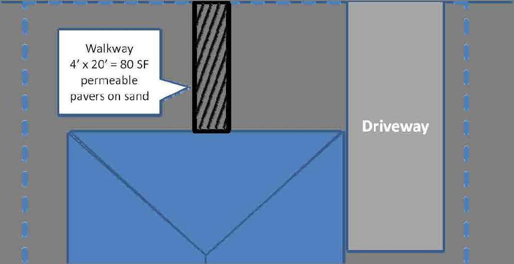
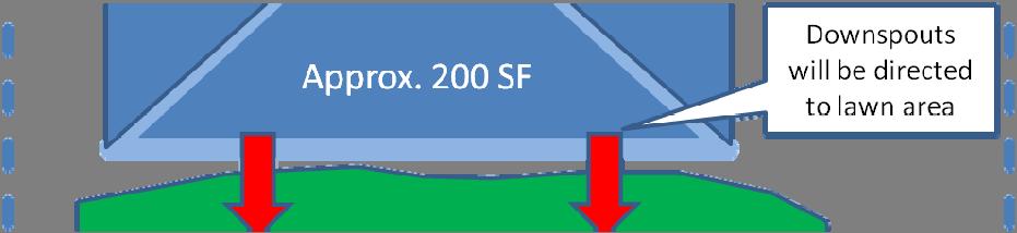

33 Example Sketch The example below illustrates the level of detail required. Not to Scale Attachment 2 - Small Projects Site Plan Sketch
34 APPENDIX 3 SCP for Regulated Projects
35 Storm Water Control Plan for Regulated Projects For Office Use Only Application No. Received By: Project Name: Physical Site Address and/or APN: Project Applicant: Mailing Address: Phone: Project Description: Instructions Based on the answers that you provided in the Stormwater Intake Form, you have determined that your project is classified as regulated for the purposes of the MS4 General Permit. Use this form to assist you in designing your project to comply with the MS4 General Permit design standards for small projects. The completed and signed Stormwater Control Plan worksheet for Small Projects, plus any applicable, approved BMP Fact Sheets, must be submitted with your application to the applicable Planning and/or Building Services with project location jurisdiction.. Type of Application/Project: What type of application is this checklist accompanying? Subdivision Building Permit Use Permit Grading Permit Design Review Other (please specify) A. Project Description Project Site Size (square feet or acres): Area of new or replaced impervious surface (square feet): Name and address of project consultant, if any (e.g., engineer, architect, designer): Regulated Projects SCP
36 Storm Water Control Plan for Regulated Projects If your project includes more than 5,000 square feet in new or replaced impervious area, is your project one of the following project types? Detached single family homes that create and/or replace 2,500 square feet or more and are not part of a larger plan of development Sidewalks built as part of new streets or roads and built to direct storm water runoff to adjacent vegetated areas Bicycle lanes that are built as part of new streets or roads that direct storm water runoff to adjacent vegetated areas Impervious trails built to direct storm water runoff to adjacent vegetated areas, or other non-erodible permeable areas Sidewalks, bicycle lanes, or trails constructed with permeable surfaces Grinding and resurfacing of existing roadways and parking lots Construction of new sidewalks, pedestrian ramps, or bike lanes on existing roadways Routine replacement of damaged pavement such as pothole repair, or replacement of short, noncontiguous sections of roadway Yes No If you answered Yes above, your project is a non-regulated project under the definitions in the MS4 General Permit. Please use the Stormwater Control Plan for Non-Regulated Projects to assist you in your project design and application submittal. B. Site Assessment (Opportunities and Constraints) 1. Soil Characteristics I. Soil characterization method II. Were infiltration rates assessed for the site? Yes No If Yes, please attach soils testing report 2. Depth to Groundwater I. What is the depth (below ground surface) to groundwater (in feet)? II. How was this determined? 3. Existing Vegetation and Natural Areas I. Are there any key natural vegetation areas, sensitive habitats, or mature trees on the site? Yes No If yes, please draw and label these features on the existing conditions site plan map, and attach to this document a description of them. Regulated Projects SCP
37 Storm Water Control Plan for Regulated Projects 4. Drainage and Hydrograph I. Are there any natural drainage or wet area features such as such as: natural ponds, springs, vernal pools, marshes, and wet meadows on the site or directly adjacent to the site? Yes No If yes, consult with applicable PBS department staff with jurisdiction for project location as additional project area restrictions may apply. 5. Potential Contamination I. Is the project site within or near to a registered contaminated site, according to the State Water Resources Control Board Geotracker Website ( Yes No If yes, please attach the applicable contaminated site report from the Geotracker website, and note the location of the contaminated site on the existing conditions site plan map. Please attach a description how this contamination will affect your project design. C. Project Layout Optimization Optimizing the site layout can be done through the following methods: 1. Define the development envelope and protected areas, identifying areas that are most suitable for development and areas to be left undisturbed. 2. Concentrate development on portions of the site with less permeable soils and preserve areas that can promote infiltration. 3. Limit overall impervious coverage of the site from paving and roofs. 4. Set back development from creek, wetlands, and riparian habitats, to maximize vegetative buffer widths. 5. Preserve significant trees. 6. Conform the site layout along natural landforms. 7. Avoid excessive grading and disturbance of vegetation and soils. 8. Replicate the site s natural drainage patterns. 9. Detain and retain runoff throughout the site. Based on the features included in the existing conditions site plan, please ensure your project site plan applies project layout optimization measures to the greatest extent practicable, while still meeting the objectives of your project. Please attach a short description on how the project has utilized site optimization methods. D. Source Controls Does your project contain potential pollutant-generating activities or sources? Yes No If Yes, please complete the Source Control Worksheet (Appendix 4) and, list and identify the source or treatment control measure and locations and include as an attachment to the SCP document. E. Drainage Management Areas Regulated Projects SCP
38 Storm Water Control Plan for Regulated Projects On the project site plan please delineate and label all drainage management areas (refer to Sec. 4 of the manual). Record the DMA names and Areas in the table below. Table 1. DMAs DMA name Area (square feet) F. Site Design Measures Please identify the site design measures incorporated into the project design and attach the applicable, approved BMP Fact Sheet or equivalent to this checklist. These measures must be discussed in the SCP and shown on the site design map. Rooftop and Impervious Area Disconnection Tree Planting and Preservation Rain Barrels and Cisterns Porous Pavement Flow-Through Planter Bioretention Regulated Projects SCP
39 Storm Water Control Plan Worksheet for Regulated Projects Table 2. Area Calculations of Self-retaining Areas Used to Treat Impervious Areas 1 2 DMA Name Area (sq. ft.) Table 3. Runoff Factor (surface type) Roofs and Paving 1.0 Landscaped Area 0.1 Bricks or solid pavers- grouted 1.0 Bricks or solid Pavers-on sand 0.5 base Pervious Concrete Asphalt 0.1 Turfblock or gravel 0.1 Open or Porous pavers 0.1 Tables 4-6 below should be used to quantify the amount of runoff that is reduced by using site design measures. Using the tables in chronological order will calculate the minimum size for your bioretention facility in order to meet the MS4 permit requirements. Several iterations may be need to size facilities according to the site design. Table 4. Area draining to self-retaining areas DMA Name (must correspond to area on the site map and on Table 1) DMA Area (sq. ft.) (Table 1) Type of Surface (Runoff Factor Table 3) Surface with Runoff Factor Column 2 X Column 3 Area of Self-retaining Area Receiving the Runoff (Table 2, Col. 2) Example 700 Roof (1.0) Ratio Col. 5 : Col. 4 Not to exceed 3.5:1 ratio (if number exceeds 3.5:1 use table 5-6 to reduce tributary area and recalculate or go directly to Table 7) 7:1 (must use site design measures, bioretention or both) Regulated Projects SCP
40 Storm Water Control Plan Worksheet for Regulated Projects Table 5. Tree Planting and Preservation (if not planting trees go to Table 6) DMA Name (must correspond to area on the site map) DMA sq. ft. (from Table 4. Col. 6) Deciduous (Input 100 for each deciduous tree) Evergreen (Input 200 for each evergreen tree) Total Tree Credit (Col. 4 + Col. 5) (DMA runoff reduction) New DMA Area Col. 2 Col. 5 (for use in Table 6-8) Example (new DMA size that must be treated with methods below Table 6-7) Table 6. Rain Barrels and Cisterns (if not using Rain Barrels or Cisterns go to Table 8) DMA Name (must correspond to area on the site map) New DMA sq. ft. (Table 5 Col. 7 or if no trees used, value from Table 4 Col. 2) Number of Rain Barrels Runoff Reduction from using a standard 55 gallon Rain Barrel = 138 sq. ft. Use the following if size is other than the standard (for every gallon of storage approx. 2.5 sq. ft. of reduction is achieved) Col. 3 X Col. 4 (DMA runoff reduction) Example New DMA Area Col. 2 - Col (go to Table 7 to recalculate Ratio) Regulated Projects SCP
41 Storm Water Control Plan Worksheet for Regulated Projects Table 7. New Tabulation of areas draining to self-retaining area after use of site design measures (must achieve a 2:1 ratio; if not achievable, use table 8 to calculate the size of bioretention required) DMA Name (must correspond to area on the site map) New Square footage of DMA (Col 6, Table 4,5,6) Area of Self-retaining Area Receiving the Runoff (Table 2, Col. 2) Ratio Column 2 : Column 3 Not to exceed 3.5:1 Example 362 (Table 6) 100 (still exceeds 3.5:1 go back, add more trees, rain barrels, or use bioretention example uses bioretention, Table 8) Regulated Projects SCP
42 Storm Water Control Plan Worksheet for Regulated Projects Table 8. Tabulation of areas draining to Bioretention Facility DMA Name (must correspond to area on the site map) DMA sq. ft. (Table 1, Col 2) or new DMA sq. ft. Table 7, Col. 2) Runoff Factor Table 6a (skip if coming from Table 1) DMA Area Col. 2 x Col. 3 Standard Sizing Factor Minimum facility size Col. 5 X Col. 6 If site does not allow for the minimum size, recalculate DMA using additional Site Design Measures to further reduce the tributary size Example (already calculated in above steps for this example) sq. ft. (proposed facility size from site plans) Table 6a. Runoff Factors Roofs and Paving 1.0 Landscaped Area 0.1 Bricks or solid pavers- grouted 1.0 Bricks or solid Pavers-on sand 0.5 base Pervious Concrete Asphalt 0.1 Turfblock or gravel 0.1 Open or Porous pavers 0.1 Regulated Projects SCP
43 Storm Water Control Plan Worksheet for Regulated Projects G. Operation and Maintenance in Perpetuity Indicate whether an Operation and Maintenance Plan is accompanying this document (Appendix 9). Yes No H. Stormwater Control Plan A Stormwater Control Plan is required for all Regulated Projects. This worksheet is designed to be the SCP if all requested descriptions and site plans have been attached. This document will be used by the plan checker to confirm that adequate storm water control measures are being implemented on the project. Indicate whether all supporting descriptions and worksheets are accompanying this document, Stormwater Control Plan Yes No I. Signature and Certification: I, the below signed, confirm that I have accurately described my project to the best of my ability, and that I have not purposely omitted any detail affecting my project s classification for storm water regulation. I hereby certify that the site design measures and storm water flow treatment measures identified herein as being incorporated into my project have been designed in accordance with the approved BMP Fact Sheet or equivalent, which is attached to this checklist, and is included in the final site plans submitted to the applicable Planning and/or Building Services Department with project location jurisdiction. I also hereby certify that my project meets the storm water runoff reduction criteria identified in the SCP, or as determined through other approved means. Signature Date Print Name I am the: Property Owner Contractor Applicant Regulated Projects SCP
44 Applicant Checklist for Regulated Projects; items that must be included in the Permit Packet Items that must be on the Project Site Map Exiting natural hydrological features (depressions watercourses, wetlands, riparian areas, undisturbed natural areas, significant natural resource areas) Existing and proposed site drainage network and connections to MS4 conveyances off-site Proposed design features and surface treatments used to minimize imperviousness and reduce runoff DMAs are delineated for the entire site and each is labeled with a unique identifier and is characterized as draining to self-retaining, self-treating, or draining to a bioretention facility Proposed locations and footprints of bioretention facilities Pollutant-generating source areas, including loading docks, food service areas, refuse areas, outdoor processes and storage, vehicle cleaning, repair or maintenance, fuel dispensing, equipment washing, etc (Appendix 4) Contents of Storm Water Control Plan (SCP) Narrative or description of site features and conditions that constrain or provide opportunities for storm water control Narrative of Site Design characteristics, building features, and pavement selections that reduce imperviousness of the site including the quantified runoff reduction. Completed tables showing square footage of proposed pervious and impervious areas, selftreating areas, self-retaining areas, areas draining to bioretention facilities, Preliminary designs, including calculations, for each bioretention facility. Elevations should show sufficient hydraulic head for each bioretention facility. General Maintenance requirements for bioretention facilities Statement accepting responsibility for interim operation and maintenance of facilities Storm water Construction Checklist Certification by professional civil engineer, architect, or landscape architect
45 APPENDIX 4 Pollutant Sources/Source Controls Checklist and BMPs
46 Stormwater Pollutant Sources/Source Controls Checklist How to use this worksheet (also see instructions on Checklist for Regulated Projects): 1 Review Column 1 and identify which of these potential sources of stormwater pollutants apply to your site. Check each box that applies. 2 Review Column 2 and incorporate all of the corresponding applicable Structural Source Control BMPs in your Stormwater Control Plan drawings. 3 Review Columns 3 and 4 and incorporate all of the corresponding applicable Structural Source Control BMPs and Operational Source Control BMPs in a table in your Stormwater Control Plan. Use this table and an accompanying narrative in the SCP, and explain any special conditions or situations that required omitting BMPs or substituting alternative BMPs. IF THESE SOURCES WILL BE ON THE PROJECT SITE 1 Potential Sources of Runoff Pollutants A. On site storm drain inlets (unauthorized non stormwater discharges and accidental spills or leaks) THEN YOUR STORMWATER CONTROL PLAN (SCP) SHOULD INCLUDE THESE SOURCE CONTROL BMPS 2 Structural Source Controls Show on SCP Drawings Location of inlets 3 Structural Source Control List in SCP Table and Narrative Mark all inlets with the words No Dumping! Flows to River/Ocean or similar. 4 Operational Source Control BMPs Include in SCP Table and Narrative Maintain and periodically repaint or replace inlet markings. Provide stormwater pollution prevention information to new site owners, lessees, or operators. See applicable operational BMPs in Fact Sheet SC 74, Drainage System Maintenance, in the CASQA Stormwater Quality Handbooks at bmphandbook Include the following in lease agreements: Tenant shall not allow anyone to discharge anything to storm drains or to store or deposit materials so as to create a potential discharge to storm drains.
47 IF THESE SOURCES WILL BE ON THE PROJECT SITE 1 Potential Sources of Runoff Pollutants B. Interior floor drains and elevator shaft sump pumps THEN YOUR STORMWATER CONTROL PLAN (SCP) SHOULD INCLUDE THESE SOURCE CONTROL BMPS 2 Structural Source Controls Show on SCP Drawings Show drain and pump locations 3 Structural Source Control List in SCP Table and Narrative State that interior floor drains and elevator shaft sump pumps will be plumbed to sanitary sewer C. Interior parking garages Show drain locations State that parking garage floor drains will be plumbed to the sanitary sewer 4 Operational Source Control BMPs Include in SCP Table and Narrative Inspect and maintain drains to prevent blockages and overflow. Inspect and maintain drains to prevent blockages and overflow. D 1. Need for future indoor & structural pest control D 2. Landscape/ Outdoor Pesticide Use/Building and Grounds Maintenance Show locations of native trees or areas of shrubs and ground cover to be undisturbed and retained. Show self retaining landscape areas, if any. Show bioretention facilities. (See instructions in Section 4 of manual.) Note building design features that discourage entry of pests State that final landscape plans will accomplish all of the following. Preserve existing native trees, shrubs, and ground cover to the maximum extent possible. Design landscaping to minimize irrigation and runoff, to promote surface infiltration where appropriate, and to minimize the use of fertilizers and pesticides that can contribute to stormwater pollution. Provide Integrated Pest Management information to owners, lessees, and operators. Maintain landscaping using minimum or no pesticides. See applicable operational BMPs in Fact Sheet SC 41, Building and Grounds Maintenance, in the CASQA Stormwater Quality Handbooks at bmphandbook Provide IPM information to new owners, lessees and operators. Where landscaped areas are used to retain or detain stormwater, specify plants that are tolerant of saturated soil conditions. Consider using pest resistant plants, especially adjacent to hardscape. To insure successful establishment, select plants appropriate to site soils, slopes, climate, sun, wind, rain, land use, air movement, ecological consistency, and plant interactions.
48 IF THESE SOURCES WILL BE ON THE PROJECT SITE 1 Potential Sources of Runoff Pollutants E. Pools, spas, ponds, decorative fountains, and other water features F. Food Service G. Refuse areas THEN YOUR STORMWATER CONTROL PLAN (SCP) SHOULD INCLUDE THESE SOURCE CONTROL BMPS 2 Structural Source Controls Show on SCP Drawings Show location of water feature and a sanitary sewer cleanout in an accessible area within 10 feet. For restaurants, grocery stores, and other food service operations, show location (indoors or in a covered area outdoors) of a floor sink or other area for cleaning floor mats, containers, and equipment. On the drawing, show a note that this drain will be connected to a grease interceptor before discharging to the sanitary sewer Show where site refuse and recycled materials will be handled and stored for pickup. See local municipal requirements for sizes and other details of refuse areas. If dumpsters or other receptacles are outdoors, show how the designated area will be covered, graded, and paved to prevent run on and show locations of berms to prevent runoff from the area. Any drains from dumpsters, compactors, and tallow bin areas shall be connected to a grease removal device before discharge to sanitary sewer. 3 Structural Source Control List in SCP Table and Narrative If the local municipality requires pools to be plumbed to the sanitary sewer, place a note on the plans and state in the narrative that this connection will be made according to local requirements. Describe the location and features of the designated cleaning area. Describe the items to be cleaned in this facility and how it has been sized to insure that the largest items can be accommodated. State how site refuse will be handled and provide supporting detail to what is shown on plans. State that signs will be posted on or near dumpsters with the words Do not dump hazardous materials here or similar. 4 Operational Source Control BMPs Include in SCP Table and Narrative See applicable operational BMPs in Fact Sheet SC 72, Fountain and Pool Maintenance, in the CASQA Stormwater Quality Handbooks at bmphandbook The sanitary sewer operator must be notified and a clean out identified when pools are to be drained to the sanitary sewer. State maintenance schedule for grease interceptor State how the following will be implemented: Provide adequate number of receptacles. Inspect receptacles regularly; repair or replace leaky receptacles. Keep receptacles covered. Prohibit/prevent dumping of liquid or hazardous wastes. Post no hazardous materials signs. Inspect and pick up litter daily and clean up spills immediately. Keep spill control materials available on site. See Fact Sheet SC 34, Waste Handling and Disposal in the CASQA Stormwater Quality Handbooks at bmphandbook
49 IF THESE SOURCES WILL BE ON THE PROJECT SITE 1 Potential Sources of Runoff Pollutants THEN YOUR STORMWATER CONTROL PLAN (SCP) SHOULD INCLUDE THESE SOURCE CONTROL BMPS 2 Structural Source Controls Show on SCP Drawings 3 Structural Source Control List in SCP Table and Narrative H. Industrial Process area Show process area. If industrial processes are to be located on site, state: All process activities to be performed indoors. No processes to drain to exterior or to storm drain system. I. Outdoor storage of equipment or materials (See rows J and K for source control measures for vehicle cleaning, repair, and maintenance.) Show any outdoor storage areas, including how materials will be covered. Show how areas will be graded and bermed to prevent run on or run off from area. Storage of non hazardous liquids shall be covered by a roof and/or drain to the sanitary sewer system, and be contained by berms, dikes, liners, or vaults. Storage of hazardous materials and wastes must be in compliance with the local hazardous materials ordinance and a Hazardous Materials Management Plan for the site. Include a detailed description of materials to be stored, storage areas, and structural features to prevent pollutants from entering storm drains. Where appropriate, reference documentation of compliance with the requirements of programs for: Hazardous Waste Generation Hazardous Materials Release Response and Inventory California Accidental Release (CalARP) Aboveground Storage Tank Uniform Fire Code Article 80 Section 103(b) & (c) 1991 Underground Storage Tank 4 Operational Source Control BMPs Include in SCP Table and Narrative See Fact Sheet SC 10, Non Stormwater Discharges in the CASQA Stormwater Quality Handbooks at bmphandbook See the Fact Sheets SC 31, Outdoor Container Storage and SC 33, Outdoor Storage of Raw Materials in the CASQA Stormwater Quality Handbooks at bmphandbook
50 IF THESE SOURCES WILL BE ON THE PROJECT SITE 1 Potential Sources of Runoff Pollutants J. Vehicle and Equipment Cleaning THEN YOUR STORMWATER CONTROL PLAN (SCP) SHOULD INCLUDE THESE SOURCE CONTROL BMPS 2 Structural Source Controls Show on SCP Drawings Show on drawings as appropriate: (1) Commercial/industrial facilities having vehicle/ equipment cleaning needs shall either provide a covered, bermed area for washing activities or discourage vehicle/equipment washing by removing hose bibs and installing signs prohibiting such uses. 3 Structural Source Control List in SCP Table and Narrative If a car wash area is not provided, describe measures taken to discourage on site car washing and explain how these will be enforced. 4 Operational Source Control BMPs Include in SCP Table and Narrative Describe operational measures to implement the following (if applicable): Wash water from vehicle and equipment washing operations shall not be discharged to the storm drain system. Car dealerships and similar may rinse cars with water only. (2) Multi dwelling complexes shall have a paved, bermed, and covered car wash area (unless car washing is prohibited on site and hoses are provided with an automatic shut off to discourage such use). See Fact Sheet SC 21, Vehicle and Equipment Cleaning, in the CASQA Stormwater Quality Handbooks at bmphandbook (3) Washing areas for cars, vehicles, and equipment shall be paved, designed to prevent run on to or runoff from the area, and plumbed to drain to the sanitary sewer. (4) Commercial car wash facilities shall be designed such that no runoff from the facility is discharged to the storm drain system. Wastewater from the facility shall discharge to the sanitary sewer, or a wastewater reclamation system shall be installed.
51 IF THESE SOURCES WILL BE ON THE PROJECT SITE 1 Potential Sources of Runoff Pollutants K. Vehicle and Equipment Repair and Maintenance THEN YOUR STORMWATER CONTROL PLAN (SCP) SHOULD INCLUDE THESE SOURCE CONTROL BMPS 2 Structural Source Controls Show on SCP Drawings Accommodate all vehicle equipment repair and maintenance indoors. Or designate an outdoor work area and design the area to prevent run on and runoff of stormwater. Show secondary containment for exterior work areas where motor oil, brake fluid, gasoline, diesel fuel, radiator fluid, acid containing batteries or other hazardous materials or hazardous wastes are used or stored. Drains shall not be installed within the secondary containment areas. Add a note on the plans that states either (1) there are no floor drains, or (2) floor drains are connected to wastewater pretreatment systems prior to discharge to the sanitary sewer and an industrial waste discharge permit will be obtained. 3 Structural Source Control List in SCP Table and Narrative State that no vehicle repair or maintenance will be done outdoors, or else describe the required features of the outdoor work area. State that there are no floor drains or if there are floor drains, note the agency from which an industrial waste discharge permit will be obtained and that the design meets that agency s requirements. State that there are no tanks, containers or sinks to be used for parts cleaning or rinsing or, if there are, note the agency from which an industrial waste discharge permit will be obtained and that the design meets that agency s requirements. 4 Operational Source Control BMPs Include in SCP Table and Narrative In the Stormwater Control Plan, note that all of the following restrictions apply to use the site: No person shall dispose of, nor permit the disposal, directly or indirectly of vehicle fluids, hazardous materials, or rinse water from parts cleaning into storm drains. No vehicle fluid removal shall be performed outside a building, nor on asphalt or ground surfaces, whether inside or outside a building, except in such a manner as to ensure that any spilled fluid will be in an area of secondary containment. Leaking vehicle fluids shall be contained or drained from the vehicle immediately. No person shall leave unattended parts or other open containers containing vehicle fluid, unless such containers are in use or in an area of secondary containment. See Fact Sheet SC 22, Vehicle and Equipment Repair in the CASQA Stormwater Quality Handbooks at bmphandbook
52 IF THESE SOURCES WILL BE ON THE PROJECT SITE 1 Potential Sources of Runoff Pollutants L. Fuel Dispensing Areas THEN YOUR STORMWATER CONTROL PLAN (SCP) SHOULD INCLUDE THESE SOURCE CONTROL BMPS 2 Structural Source Controls Show on SCP Drawings Fueling areas shall have impermeable floors (i.e., portland cement concrete or equivalent smooth impervious surface) that are: a) graded at the minimum slope necessary to prevent ponding; and b) separated from the rest of the site by a grade break that prevents run on of stormwater to the maximum extent practicable. Fueling areas shall be covered by a canopy that extends a minimum of ten feet in each direction from each pump. [Alternative: The fueling area must be covered and the cover s minimum dimensions must be equal to or greater than the area within the grade break or fuel dispensing area1.] The canopy [or cover] shall not drain onto the fueling area 3 Structural Source Control List in SCP Table and Narrative State that no vehicle repair or maintenance will be done outdoors, or else describe the required features of the outdoor work area. State that there are no floor drains or if there are floor drains, note the agency from which an industrial waste discharge permit will be obtained and that the design meets that agency s requirements. State that there are no tanks, containers or sinks to be used for parts cleaning or rinsing or, if there are, note the agency from which an industrial waste discharge permit will be obtained and that the design meets that agency s requirements. 4 Operational Source Control BMPs Include in SCP Table and Narrative The property owner shall dry sweep the fueling area routinely. See Fact Sheet SC 20, Vehicle and Equipment Fueling in the CASQA Stormwater Quality Handbooks at bmphandbook
53 IF THESE SOURCES WILL BE ON THE PROJECT SITE 1 Potential Sources of Runoff Pollutants M. Loading Docks THEN YOUR STORMWATER CONTROL PLAN (SCP) SHOULD INCLUDE THESE SOURCE CONTROL BMPS 2 Structural Source Controls Show on SCP Drawings Show the loading dock area, including roofing and drainage. Loading docks shall be covered and/or graded to minimize run on to and runoff from the loading area. Roof downspouts shall be positioned to direct stormwater away from the loading area. Water from loading dock areas shall be drained to the sanitary sewer, or diverted and collected for ultimate discharge to the sanitary sewer. 3 Structural Source Control List in SCP Table and Narrative 4 Operational Source Control BMPs Include in SCP Table and Narrative Move loaded and unloaded items indoors as soon as possible. See Fact Sheet SC 30, Outdoor Loading and Unloading, in the CASQA Stormwater Quality Handbooks at bmphandbook Loading dock areas draining directly to the sanitary sewer shall be equipped with a spill control valve or equivalent device, which shall be kept closed during periods of operation. Provide a roof overhang over the loading area or install door skirts (cowling) at each bay that enclose the end of the trailer. N. Fire Sprinkler Test Water Provide a means to drain fire sprinkler test water to the sanitary sewer See the note in Fact Sheet SC 41, Building and Grounds Maintenance, in the CASQA Stormwater Quality Handbooks at handbook
54 IF THESE SOURCES WILL BE ON THE PROJECT SITE 1 Potential Sources of Runoff Pollutants O. Miscellaneous Drain or Wash Water or Other Sources Boiler drain lines THEN YOUR STORMWATER CONTROL PLAN (SCP) SHOULD INCLUDE THESE SOURCE CONTROL BMPS 2 Structural Source Controls Show on SCP Drawings Show drain lines and drainage sumps 3 Structural Source Control List in SCP Table and Narrative Boiler drain lines shall be directly or indirectly connected to the sanitary sewer system and may not discharge to the storm drain system. 4 Operational Source Control BMPs Include in SCP Table and Narrative If architectural copper is used, implement the following BMPs for management of rinse water during installation: Condensate drain lines Rooftop equipment Drainage sumps Roofing, gutters, and trim Other sources P. Plazas, sidewalks, and parking lots. Show extent of permeable paving materials Condensate drain lines may discharge to landscaped areas if the flow is small enough that runoff will not occur. Condensate drain lines may not discharge to the storm drain system. Rooftop equipment with potential to produce pollutants shall be roofed and/or have secondary containment. Any drainage sumps on site shall feature a sediment sump to reduce the quantity of sediment in pumped water. Include controls for other sources as specified by local reviewer. If possible, purchase copper materials that have been pre patinated at the factory. If patination is done on site, prevent rinse water from entering storm drains by discharging to landscaping or by collecting in a tank and hauling off site. Consider coating the copper materials with an impervious coating that prevents further corrosion and runoff. Implement the following BMPs during routine maintenance: Prevent rinse water from entering storm drains by discharging to landscaping or by collecting in a tank and hauling off site. Sweep plazas, sidewalks, and parking lots regularly to prevent accumulation of litter and debris. Collect debris from pressure washing to prevent entry into the storm drain system. Collect wash water containing any cleaning agent or degreaser and discharge to the sanitary sewer not to a storm drain.


55


56


57


58


59


60


61


62


63


64
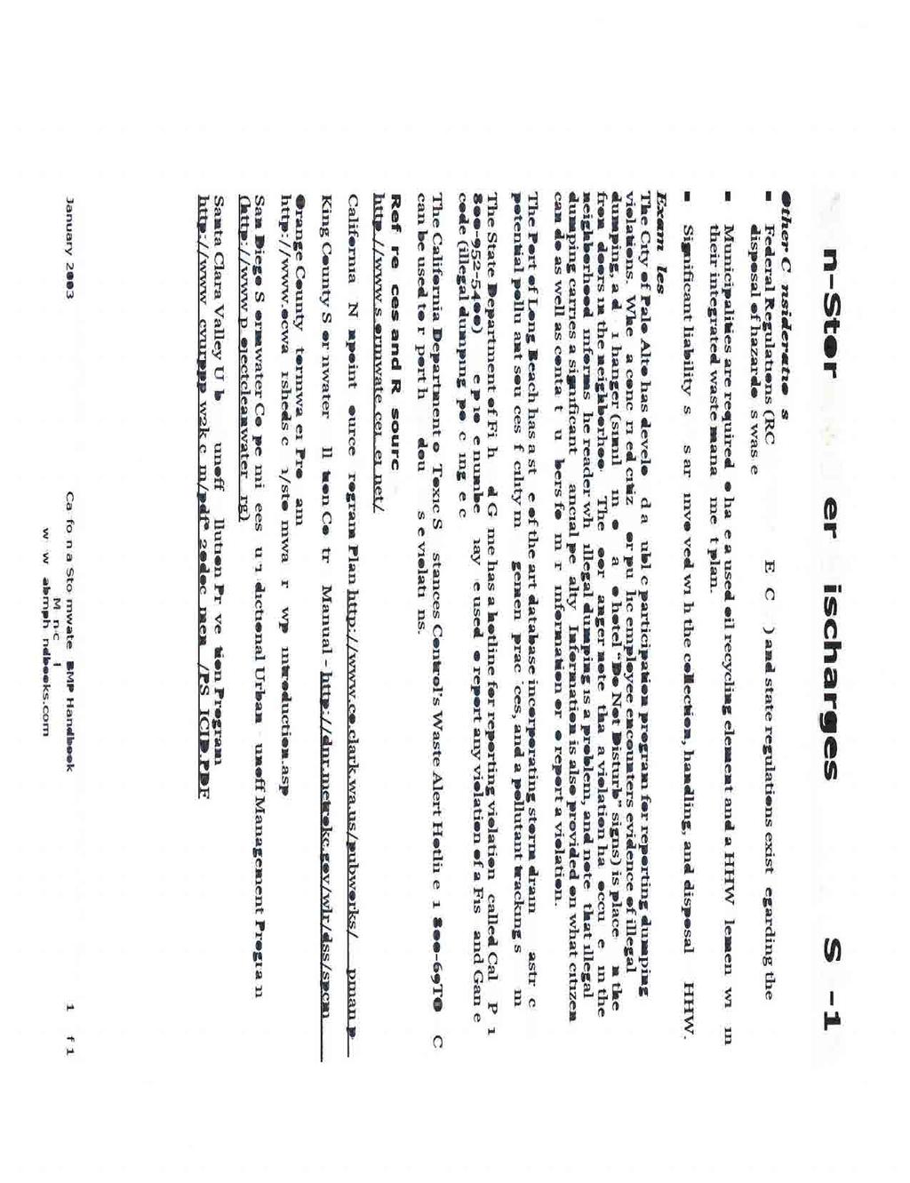


65


66
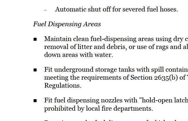
67
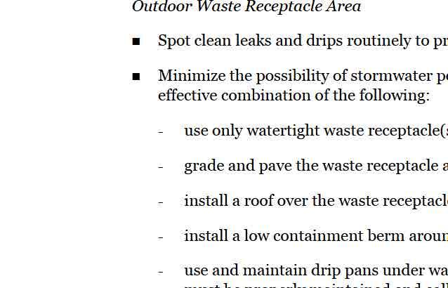
68
69
70
71


72


73


74


75
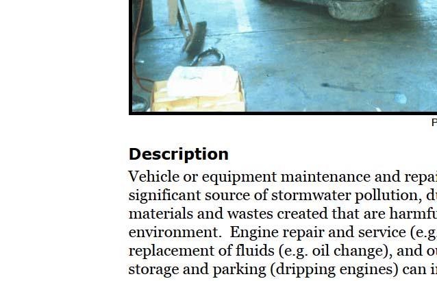
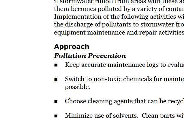
76
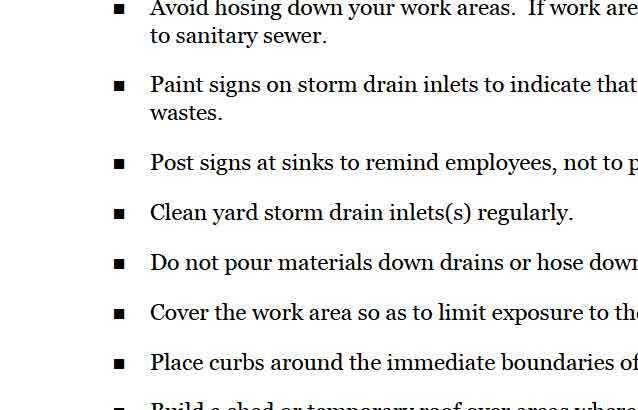
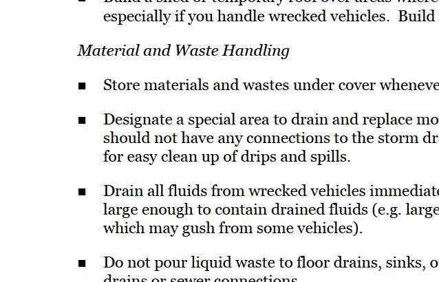
77

78
79
80

81


82


83


84


85


86


87


88


89


90


91


92

93


94


95


96


97


98
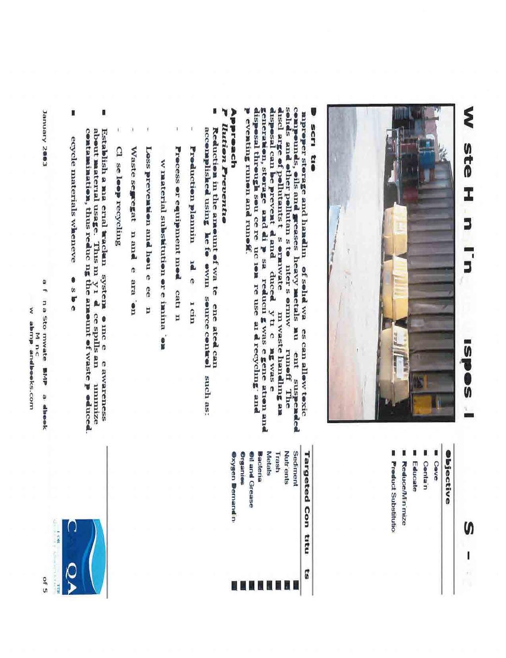


99


100


101


102


103
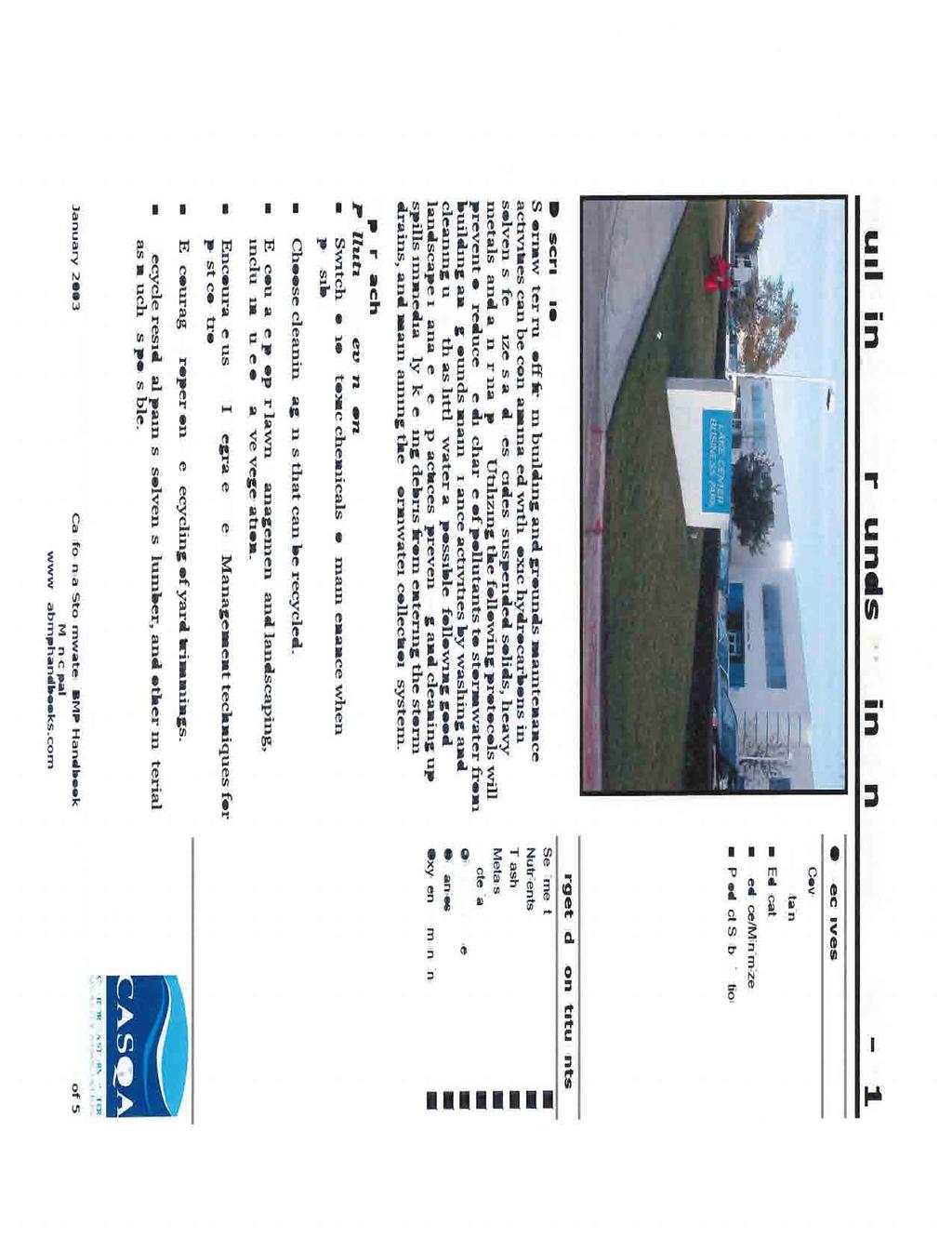


104


105


106


107


108


109


110


111


112
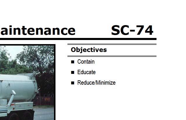
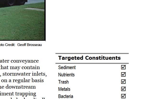
113
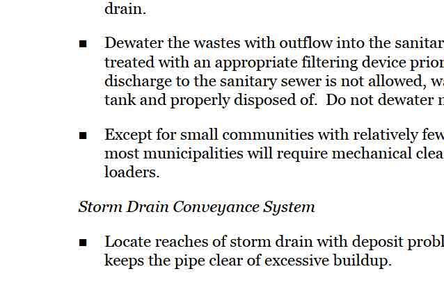
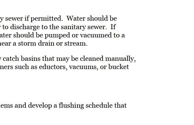
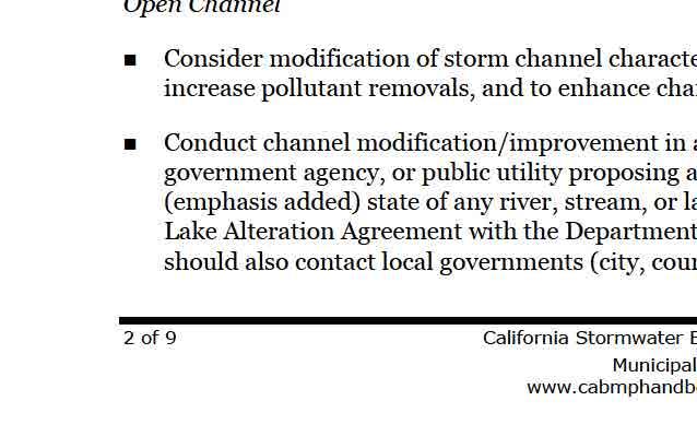
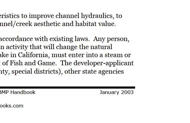
114
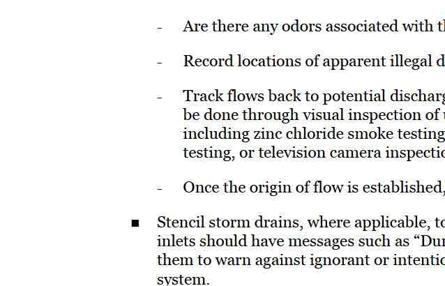
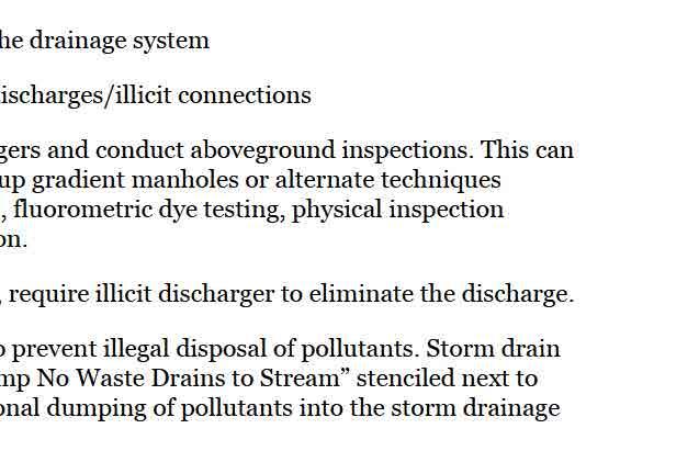
115
116


117
118
119
120
121
122 APPENDIX 5 Bioretention Specifications and Checklist


 Min.")
 seal penetration with grout 3 max.")
 class 2 permeable material 4 min.")


 - Facilities located in areas of high")


123 Bioretention Facility not to scale adjacent pavement curb cut or curb inlet if needed 4 min. diameter. SDR 35 or equivalent sweep bend and cleanout min. 2 above overflow level Overflow Structure concrete drop inlet or manhole with frame, atrium or beehive grate,¼ openings Walls as needed to establish constant rim elevation around facility cobbles or splash block Min. 6 Top of soil layer (TSL) Min. 18 specified soil mix install all plantings to maintain TSL at or below specified elevation Schedule 80 (no perforations) seal penetration with grout 3 max. mulch if specified by plans Top of gravel layer (TGL) Min. 12 Bottom of gravel layer (BGL) class 2 permeable material 4 min. diameter SDR 35 or equivalent perforations facing down bend or slope so discharge is at TGL elevation to storm drain cutoff wall if needed to protect structures or pavement Native Soil Allowed variations for special site conditions: - Facilities located within 10 feet of structures or other potential geotechnical hazards may incorporate an impervious cutoff wall - Facilities with documented high concentrations of pollutants in underlying soil or groundwater, facilities where infiltration could contribute to a geotechnical hazard, and facilities located on elevated plazas or others structures may incorporate an impervious liner between the native soil and the BGL and locate the underdrain discharge at the BGL (flow-through planter configuration) - Facilities located in areas of high groundwater, highly infiltrative soils, or where connection of the underdrain to a surface drain or subsurface storm drain are infeasible may omit the underdrain Notes: - No liner, no filter fabric, no landscape cloth. - Maintain BGL, TGL, and TSL throughout facility area at elevations to be specified in plan. - Class 7 permeable layer may extend below and underneath drop inlet. - Elevation or underdrain discharge is at top of gravel layer. - See Section 4 of Manual for instructions on facility sizing and additional specifications
124 Bioretention Facility - Overview not to scale Overflow structure 6 spacing of underdrain pipes is typically adequate curb inlets may be utilized if slope is greater than 2% Multiple inlets are O.K. Use cobble or splash block to dissipate energy surface area of soil mix that will flood before facility overflows separate facility from adjacent landscaping with a wall or curb It is O.K. to slope soil mix against curb to reduce drop-off and /or use plantings to discourage entry soil mix 6 min. avg. depth gravel mix Note: Show all elevations of curb, pavement, inlet, top of soil layer (TSL), top of gravel layer (TGL), and bottom of gravel layer (BGL) at all inlets and outlets and at key points along edge of facility.
125 Soil/Compost and Gravel Specifications for Bioretention Facility Compost shall be a well-decomposed, stable, weed-free organic matter source derived from waste materials including yard debris, wood wastes or other organic materials not including manure or biosolids, and shall meet the standards developed by the US Composting Council (USCC). The product shall be certified through the USCC Seal of Testing Assurance (STA) Program (a compost testing and information disclosure program). Compost Quality Analysis: Before delivery of the soil, the supplier shall submit a copy of the lab analysis performed by a laboratory that is enrolled in the USCC s Compost Analysis Proficiency (CAP) program and using approved Test Methods for the Evaluation of Composting and Compost (TMECC). The lab report shall verify that the compost parameters are within the limits specified below. Parameter Range Reported as (units) Organic Matter Content %, dry weight basis Carbon to Nitrogen Ratio 15:1 to 25:1 ratio Maturity (Seed Emergence and Seedling Vigor) >80 average % of control Stability (CO₂ Evolution Rate) <8 mg C0₂-C/g unit OM/day Soluble Salts (Salinity) <6.0 mmhos/cm ph Heavy Metals Content Pathogens Fecal coliform Salmonella May vary with plant species PASS PASS PASS Nutrient Content (provide analysis, including): Total Nitrogen (N) 0.9 % units Boron (Total B) <80 ppm Calcium (Ca) For information only % Sodium (Na) For information only % Magnesium (Mg) For information only % Sulfur (S) For information only % PASS/FAIL: US EPA Class A standard, 40 CFR , tables 1 and 3. PASS/FAIL: US EPA Class A standard, 40 CFR (a) levels PASS/FAIL: US EPA Class A standard, 40 CFR (a) levels
126 Soil/Compost and Gravel Specifications for Bioretention Facility Gravel Layer The gravel layer used in the bioretention facility must consist of Class 2 Permeable Material as specified in the State of California s Business, Transportation and Housing Agency, Department of Transportation; Standard Specifications 2010, manual ( s.pdf). The specific section, Subsurface Drains, Sec. 68, of the manual is used because it offers specific specifications for subsurface drains. In addition to the standardized permeable layer, a membrane layer of pea gravel or other intermediate-sized material is recommended at the top of the gravel layer to prevent fines from the soil/compost layer from moving downward into the gravel layer F (1) General Permeable material for use in backfilling trenches under, around, and over underdrains must consist of hard, durable, clean sand, gravel, or crushed stone and must be free from organic material, clay balls, or other deleterious substances. Permeable material must have a durability index of not less than F (3) Class 2 Permeable Material The percentage composition by weight of Class 2 permeable material in place must comply with the grading requirements shown in the following table: Class 2 Permeable Material Grading Requirements Sieve sizes Percentage passing 1" 100 3/4" /8" No No No No No Class 2 permeable material must have a sand equivalent value of not less than 75.
127 Bioretention Facility Construction Checklist Layout (to be confirmed prior to beginning excavation permit approval stage) Square footage of the facility meets or exceeds minimum shown in Stormwater Control Plan Site grading and grade breaks are consistent with the boundaries of the tributary Drainage Management Area(s) (DMAs) shown in the Stormwater Control Plan Inlet elevation of the facility is low enough to receive drainage from the entire tributary DMA locations and elevations of overland flow or piping, including roof leaders, from impervious areas to the facility have been laid out and any conflicts resolved Rim elevation of the facility is laid out to be level all the way around, or elevations are consistent with a detailed cross-section showing location and height of interior dams Locations for vaults, utility boxes, and light standards have been identified so that they will not conflict with the facility Facility is protected as needed from construction-phase runoff and sediment Excavation (to be confirmed prior to backfilling or pipe installation) Excavation conducted with materials and techniques to minimize compaction of soils within the facility area Excavation is to accurate area and depth Slopes or side walls protect from sloughing of native soils into the facility Moisture barrier, if specified, has been added to protect adjacent pavement or structures. Native soils at bottom of excavation are ripped or loosened to promote infiltration Overflow or Surface Connection to Storm Drainage (to be confirmed prior to backfilling with any materials) Grating excludes mulch and litter (beehive or atrium-style grates recommended) Overflow is connected to storm drain via appropriately sized No knockouts or side inlets are in overflow riser Overflow is at specified elevation Overflow location selected to minimize surface flow velocity (near, but offset from, inlet recommended) Grating excludes mulch and litter (beehive or atrium-style grates recommended) Overflow is connected to storm drain via appropriately sized
128 Bioretention Facility Construction Checklist Underground connection to storm drain/outlet orifice Perforated pipe underdrain (PVC SDR 35 or approved equivalent) is installed with holes facing down Perforated pipe is connected to storm drain at specified elevation (typ. bottom of soil elevation) Cleanouts are in accessible locations and connected via sweep Drain Rock/Subdrain (to be confirmed prior to installation of soil mix) Rock is installed as specified, 12" min. depth. Class 2 permeable, Caltrans specification F(3) recommended Rock is smoothed to a consistent top elevation. Depth and top elevation are as shown in plans Slopes or side walls protect from sloughing of native soils into the facility No filter fabric is placed between the subdrain and soil mix layers Soil Mix Soil mix is as specified. Mix installed in lifts not exceeding 12" Mix is not compacted during installation but may be thoroughly wetted to encourage consolidation Mix is smoothed to a consistent top elevation. Depth of mix (18" min.) and top elevation are as shown in plans, accounting for depth of mulch to follow and required reservoir depth Irrigation Irrigation system is installed so it can be controlled separately from other landscaped areas Smart irrigation controllers and drip emitters are recommended and may be required by local code or ordinance. Spray heads, if any, are positioned to avoid direct spray into outlet structures
129 Bioretention Facility Construction Checklist Planting Plants are installed consistent with approved planting plan, consistent with site water allowance Any trees and large shrubs are staked securely No fertilizer is added; compost tea may be used No native soil or clayey material are imported into the facility with plantings 1"-2" mulch may be applied following planting; mulch selected to avoid floating Final elevation of soil mix maintained following planting Curb openings are free of obstructions Final Engineering Inspection Drainage Management Area(s) are free of construction sediment and landscaped areas are stabilized Inlets are installed to provide smooth entry of runoff from adjoining pavement, have sufficient reveal (drop from the adjoining pavement to the top of the mulch or soil mix, and are not blocked Inflows from roof leaders and pipes are connected and operable Temporary flow diversions are removed Rock or other energy dissipation at piped or surface inlets is adequate Overflow outlets are configured to allow the facility to flood and fill to near rim before overflow Plantings are healthy and becoming established Irrigation is operable Facility drains rapidly; no surface ponding is evident Any accumulated construction debris, trash, or sediment is removed from facility Permanent signage is installed and is visible to site users and maintenance personnel
130 APPENDIX 6 Bioretention Plant List - Coastal
131 Planting Zone Diagram Low Mid High Species planted in this zone should have the following characteristics: - Water tolerant; - Dense root structure and vegetative cover to discourage erosion, slow runoff velocities, and provide maximum - pollutant filtration. - Native grasses and groundcovers are excellent choices for this zone. Species planted in this zone should have the following characteristics: - Tolerant of periodic inundation; - Tolerant of periods without water; - Dense root structure to provide erosion protection of side slopes. Species planted in this zone should have the following characteristics: - Deep roots to provide structural stability to the drainage feature; -Tolerant of extended periods without water; - Tolerant of occasional inundation.
132 Plant List for Bioretention Facilities Coastal MS4 Area Botanical Name Common Name Low Mid High Low, Mid, and High refers to planting zones within the Bioretention Facility Grasses and Grass like Plants Carex ativulsa Berkeley Sedge, Grey Sedge X X X tolerates foot traffic, some drought and boggy soils Carex pansa California Meadow Sedge X X X good lawn substitute, tolerates wide range of growing conditions, seasonal inundation, drought, foot traffic and mowing Carex praegracilis Clustered Field Sedge X X useful lawn substitute and bank stabilizer, good planted in masses, tolerates wide range of growing conditions, foot traffic and mowing, may look weedy when mixed with other plants Carex spissa San Diego Sedge X a large grass, tolerates alkaline soil, clay, serpentine, seasonal inundation, and deer Chondropetalum tectorum Small Cape Rush X X X A tough, attractive reed like plant, tolerates boggy or clay soils and drought once established Festuca rubra Molate Red Fescue X X X a tufted, spreading bunchgrass, good lawn substitute, provides erosion control, tolerates wet conditions, but looks best with regular water, tolerates drought once established Juncus effusus Soft Rush X tolerates poor drainage, heavy soils, needs more supplemental water than Juncus patens Juncus patens Wire Grass, Blue Rush X Leymus condensatus Canyon Prince Wild Rye X Muhlenbergia rigens Deer Grass X strong performance in bioretention ares, tolerates poor drainage, seasonal inundation, drought, shade tolerates drought, wet, but not soggy soils, looks best with supplemental irrigation, spreads by rhizomes a large grass, tolerates sandy and clay soils, seasonal inundation, best when cut back annually to remove old thatch Perennials Achillea millefolium Yarrow X tolerates alkaline soil, sand, clay, seasonal wet conditions, foot traffic and deer, will self sow Fragaria chiloensis Beach Strawberry X vigorous spreading groundcover, tolerates sand, clay, wet conditions, prefers good drainage Iris douglasiana Douglas Iris X tolerates sand, clay and serpentine soils, seasonal wet (but not soggy) soils and drought Salvia uliginosa Bog Sage X Sisyrinchium bellum Blue eyed Grass X low growing perennial, tolerates clay, winter wet, summer drought, prefers light shade, provides nectar for birds and insects, does well under oaks a semi evergreen perennial, tolerates sand, clay, seasonal wet soils and deer, dormant in summer, but can be delayed with supplemental irrigation Solidago californica California Goldenrod X tolerates poor soils, seasonal wet and drought, can spread aggressively if over irrigated
133 Botanical Name Common Name Low Mid High Low, Mid, and High refers to planting zones within the Bioretention Facility Shrubs and Subshrubs Baccharis pilularis California Wild Rose X X X Coyote Brush Coyote Brush X X tolerates a wide variety of soils, seasonal flooding and some drought, spreads aggressively, avoid edges of walkways because of thorns adaptable evergreen shrub, provides quick cover and bank stabilization, tolerant of coastal conditions, alkaline soil, sand, clay and seasonal wet Large Shrubs Heteromeles arbutifolia Toyon X tolerates sand, clay and serpentine soils, seasonal water with good drainage Myrica californica Pacific Wax Myrtle X large shrub or small tree, tolerates coastal conditions, sand, clay and seasonal inundation Sambucus mexicana Western Elderberry X large shrub to tree, tolerates clay, seasonal flooding and drought, good wildlife food source Trees Chilopsis linearis Desert Willow X tolerates alkaline soil, sand, clay, seasonal flooding and drought, not coastal condition Platanus racemosa Western Sycamore X Quercus agrifolia Coast Live Oak X tolerates sand and clay soils, seasonal flooding, needs space to grow, avoid underground water/sewer pipes tolerates drought and winter wet conditions, mature trees produce significant litter limiting understory plantings, need space to grow Source: Sunset Magazine
134 APPENDIX 7 Bioretention Plant List - Inland


135 Planting Zone Diagram Low Mid High Species planted in this zone should have the following characteristics: - Water tolerant; - Dense root structure and vegetative cover to discourage erosion, slow runoff velocities, and provide maximum - pollutant filtration. - Native grasses and groundcovers are excellent choices for this zone. Species planted in this zone should have the following characteristics: - Tolerant of periodic inundation; - Tolerant of periods without water; - Dense root structure to provide erosion protection of side slopes. Species planted in this zone should have the following characteristics: - Deep roots to provide structural stability to the drainage feature; -Tolerant of extended periods without water; - Tolerant of occasional inundation.
136 Plant List for Bioretention Facilities Inland MS4 Area Botanical Name Common Name Low Mid High Low, Mid, and High refers to planting zones within the Bioretention Facility Grasses and Grass like Plants Bromus carinatus California brome X X Carex barbarae Santa Barbara sedge X X Not for full sun Carex brevicaulis short stem sedge X X Short turf like growth habit Carex densa dense sedge X X Carex deweyanna Dewey sedge X X Carex divulsa Berkeley sedge X X Not a native. Mistakenly sold as the native C. tumulicola Carex obnupta slough sedge X X Carex pansa California meadow sedge X X Carex rupestris curly sedge X X Carex stipata sawbeak sedge X X Carex subfusca rusty sedge X X Carex testacea New Zealand orange sedge X X Carex tumulicola foothill sedge X X X Carex vesicaria inflated sedge X X Deschampsia danthonoides annual hairgrass X X Can tolerate saturation if top soil layer drains Deschampsia cespitosa tufted hairgrass X X Can tolerate saturation if top soil layer drains Eleocharis acicularis needle spike rush X X Eleocharis macrostachya creeping spike rush X X Eleocharis ovata ovate spike rush Eleocharis palustris creeping spike rush Elymus glaucus blue wild rye X X Festuca californica California fescue X Can tolerate saturation if top soil layer drains Festuca idahoensis blue bunchgrass X Can tolerate saturation if top soil layer drains Festuca rubra red fescue X Can be mowed as turf alternative. Can tolerate saturation if top soil layer drains Glyceria occidentalis western mannagrass X X
137 Plant List for Bioretention Facilities Inland MS4 Area Botanical Name Common Name Low Mid High Low, Mid, and High refers to planting zones within the Bioretention Facility Grasses and Grass like Plants Hordeum brachyantherum meadow barley X X Can tolerate saturation if top soil drains Juncus balticus Baltic rush X X Juncus bufonis toad rush X X Juncus effusus Pacific rush X X Juncus ensofolius dagger leaf rush X X Juncus patens blue rush X X X May not need summer irrigation after establishment Juncus tenuis slender rush X X Juncus xiphiodes iris leaved rush X X Leymus triticoides creeping wild rye X X Can be mowed. Ideal plant for many uses. Melica californica California melic X Can tolerate saturation if top soil layer drains Melica imperfecta small flowered melic X Can tolerate saturation if top soil layer drains Muhlenbergia rigens deergrass X Herbaceous Plants Achilea millefolium common yarrow X Aster sp. aster X X Athyrium filix femina lady fern X X Blechnum spicant deer fern X X Camassia leichtilinii camas lily X X Camassia quamash common camas X X Epilobium canum California fuschia X Eriogonum fasciculatum flattop buckwheat X Eschscholzia californica California poppy X
138 Plant List for Bioretention Facilities Inland MS4 Area Botanical Name Common Name Low Mid High Low, Mid, and High refers to planting zones within the Bioretention Facility Herbaceous Plants Fragaria chiloensis beach strawberry X This species is adapted to low water conditions Iris douglasiana Douglas iris X X Lupinus bicolor miniature lupine X Tolerates saturation in winter only Lupinus polyphyllus large leaf lupine X X similar to Russell hybrids Mimulus guttatus X Polypodium californicum California polypody X X Polypodium glycrrhiza licorice fern X X Polystichum californicum California sword fern X X X Polystichum munitum western sword fern X X X Pteridiumn aquilinum bracken fern X X Sisyrinchium bellum blue eyed grass X Sisyrinchium californicum yellow eyed grass X X Veronica liwanensis speedwell X Source: City of Santa Rosa, Storm Water Low Impact Development Technical Design Manual, August 2011
139 APPENDIX 8 Site Design Measures


140 Rooftop and Impervious Area Disconnection (Self-retaining areas) Description Disconnection of rooftop and impervious areas from the storm drain system helps reduce runoff and provide pollutant removal as the re-directed water travels over and through vegetation and soil instead of being directly piped and discharged into the storm drain. Roof runoff is directed to spread over a vegetated area (self-retaining area) or is directed into vegetated area that drains to the MS4 system (selftreating areas) or to bioretention facilities. The following are examples of ways to implement rooftop disconnection: Splash Block Splash blocks reduce the velocity and impact of water exiting the roof downspout and direct water to a pervious area (self-retaining area). Pop-up Drainage Emitter Pop-up drainage emitters are useful in conveying storm water from roof downspouts into vegetated areas. Roof runoff is piped then released through a capped device that opens with water pressure, allowing the storm water to flow out of the emitter and into the vegetated area. Confirm that the following conditions have been met when using Self-Retaining Areas as a Source Control Measure: On Site Plan Show: Delineate the impervious DMA from where the runoff will be coming from Delineate the pervious area where the runoff will be directed to (self-retaining area) Show how the runoff will be directed to the (self-retaining area) Confirm that the following specifications will be met: Tributary area (impervious area) does not exceed more than twice the Self-retaining Area) Roof areas collect runoff and route to the self-retaining area Paved areas are slope to direct runoff to self-retaining area Runoff is dispersed across the self-retaining area (splash block or pop-up emitter) Self-retaining area has vegetation soils meeting the requirements above Drain inlets, if present, are at least 3-inches above surrounding grade (provides for the retention of the 85 th percentile 24-hr storm event (approx inch) Type A/B soils are present or native soils have been amended to increase infiltration rates Self-retaining area are basin-like shaped depressions with a maximum slope of 25% Please utilize the Storm Water Control Plan Worksheets to tabulate the runoff reduction that can be achieved using this BMP. This checklist must be included with the SCP worksheet if used as a site design measure.

. The total tributary area reduction is limited to 50% of the total tributary area.")


141 Tree Plantings/Preservation Trees intercept rain water on their leaves and branches, allowing rain water to evaporate or run down the branches and trunk of the tree where it readily infiltrates into the soil. Trees also provide shade over impervious surfaces which reduces peak flow in streams and provides shade, which reduces the heat island effects of urban areas. Technique The number and species of trees planted or preserved on a project is used in reducing the amount of tributary area that must be accounted for when calculating treatment and volume capture stormwater facilities (self-retaining, rain barrels, and bioretention). The total tributary area reduction is limited to 50% of the total tributary area. Only trees that overhang impervious areas or are within 25 ft of impervious areas can qualify for the tree credits. The following tree credits can apply: New deciduous trees provide a tributary area reduction credit of 100 ft² New evergreen trees provide a tributary area reduction credit of 200 ft² Existing trees provide a tributary area reduction credit equal to half of the existing tree canopy area existing trees must be adequately protected during construction At a minimum inspection and maintenance shall include the following: Annual inspection prior to the rainy season. Annual proper watering and application of mulch. Routine pruning and weeding as needed. Replacement of trees as needed. Please utilize the Storm Water Control Plan Worksheets for assistance with calculating the runoff reduction with this BMP. Below are the runoff reduction rates per Tree. Evergreen Deciduous 200 square feet 100 square feet

142 Rain Barrels and Cisterns Rain Barrels and Cisterns are a system that collects and stores storm water runoff from a roof or other impervious surface. These typically have overflow mechanisms or plugs that drain to a vegetated area or to the storm drain system when the barrel is full. Use of Rain Barrels and Cisterns must comply with local vector control requirements. Show the following on your site plan: Impervious area tributary to each Rain Barrel / Cistern Location of each Rain Barrel/Cistern Confirm the Following Standard Specifications have been met: Rain Barrels are sited at grade on a sound and level surface at or near the ground. Gutters tributary to the Rain Barrels/Cistern are screened with a leaf guard or maximum ½ inch to ¼ inch minimum corrosion resistant metallic hardware fabric. Water collected will be used for irrigation purposes only. Openings are screened with a corrosion resistant metallic fine mesh (1/16 inch or smaller) to prevent mosquito harborage. Large openings are secured to prevent entry by children. Rain Barrels and Cistern are cleaned annually. Please include this sheet with SCP Worksheet Submission


143 Permeable/Porous Pavement This option can be easy to install and maintain, cost-effective, and can add aesthetic value to your project. Permeable pavements may include pervious concrete, pervious asphalt, porous pavers, crushed aggregate, open pavers with grass or plantings, open pavers with gravel, or solid pavers. Show on your site plan: Location, extent and types of pervious pavements. Confirm the following standard specifications are met: No erodible areas drain on to permeable pavement. Subgrade compaction is minimal. Reservoir base course is of open-graded crushed stone. Base depth is adequate to retain rainfall (3 inches is adequate) and support design loads (more depth may be required). No subdrain is included or, if a subdrain is included, outlet elevation is a minimum of 3 inches above bottom of base course. Subgrade is uniform and slopes are not so steep that subgrade is prone to erosion. R igid edge is provided to retain granular pavements and unit pavers. Solid unit pavers, if used, are set in sand or gravel with minimum 3 / 8 inch gaps between the pavers. Joints are filled with an open-graded aggregate free of fines. Permeable concrete or porous asphalt, if used, are installed by industry-certified professionals according to the vendor s recommendations. Selection and location of pavements incorporates Americans with Disabilities Act requirements (if applicable), site aesthetics, and uses. Runoff Reduction factors to use when calculating runoff reduction of DMAs Surface Type/Pavement Type Runoff Reduction Factor Bricks or solid pavers on sand 0.5 Bricks or solid pavers, grouted 1.0 Pervious concrete/asphalt 0.1 Permeable pavement 0.1 Cobbles 0.1 Please include this sheet with SCP Worksheet Submission
Stormwater Technical Guide
 Stormwater Technical Guide Compliance with Stormwater Post-Construction Requirements in Santa Barbara County Dan Cloak, Principal Dan Cloak Environmental Consulting January 9, 2014 Introduce yourself Name
Stormwater Control Plan: Small (Tier 1) Land Development Project
 Land Development Project") Stormwater Control Plan: Small (Tier 1) Land Development Project Project ID for Tracking (for City Staff only): The California Regional Water Quality Control Board for the Central Coast Region (Water Board)
Stormwater Control Plan: Small (Tier 1) Land Development Project Project ID for Tracking (for City Staff only): The California Regional Water Quality Control Board for the Central Coast Region (Water Board)
5. LOW IMPACT DEVELOPMENT DESIGN STANDARDS
 5. LOW IMPACT DEVELOPMENT DESIGN STANDARDS Low Impact Development (LID) requires a shift in stormwater management away from conveying runoff to a small number of downstream points through hydraulically
12/31/2014 County of Mendocino s Low Impact Design Standards Manual v1.0 A P P E N D I X 8. Site Design Measures. 32 P a g e
 12/31/2014 County of Mendocino s Low Impact Design Standards Manual v1.0 A P P E N D I X 8 Site Design Measures 32 P a g e Rooftop and Impervious Area Disconnection (Self-retaining areas) Description Disconnection
Example Stormwater Control Plan For a Residential Subdivision Project. Whispering Pines Lane Anytown, USA
 Example Stormwater Control Plan For a Residential Subdivision Project Whispering Pines Lane Anytown, USA December 2, 2015 XYZ Corporation Jane Jones, 707-555-1212 This example prepared by Dan Cloak Environmental
Example Stormwater Control Plan For a Residential Subdivision Project. Whispering Pines Lane Anytown, USA. February 21, 2018
 Example Stormwater Control Plan For a Residential Subdivision Project Whispering Pines Lane Anytown, USA February 21, 2018 XYZ Corporation Jane Jones, 925-555-1212 This example prepared by Dan Cloak Environmental
Post-Construction Stormwater Management Checklist* (5,000 SF or Greater)
") Applicability: Required for projects that create and/or replace 5,000 square feet or greater of impervious surface (i.e. asphalt roads, concrete structures, building area, sidewalks, etc.). Impervious
Applicability: Required for projects that create and/or replace 5,000 square feet or greater of impervious surface (i.e. asphalt roads, concrete structures, building area, sidewalks, etc.). Impervious
Preparing a Stormwater Control Plan for a Small Land Development Project
 Preparing a Stormwater Control Plan for a Small Land Development Project Addendum to the Stormwater C.3 Guidebook December 1, 2012 Introduction As of December 1, 2012, development projects that create
6.1 Bioretention Areas
 SAN MATEO COUNTYWIDE WATER POLLUTION PREVENTION PROGRAM 6.1 Bioretention Areas Figure 6-1. Bioretention Area. Source: City of Brisbane Bioretention areas 1, or rain gardens, are concave landscaped areas
Appendices: Glossary. General Terms. Specific Terms. Low Impact Development Approaches Handbook
 67 67 General Terms Specific Terms 66 Low Impact Development Approaches Handbook The vocabulary of low impact development is evolving, and many terms are used interchangeably and to describe the same or
Example Stormwater Control Plan For a Residential Subdivision Project. Whispering Pines Lane Anytown, USA. February 21, 2018
 Example Stormwater Control Plan For a Residential Subdivision Project Whispering Pines Lane Anytown, USA February 21, 2018 XYZ Corporation Jane Jones, 925-555-1212 This example prepared by Dan Cloak Environmental
Example Stormwater Control Plan For a Commercial Project 123 Main Street Anytown, USA
 Example Stormwater Control Plan For a Commercial Project 123 Main Street Anytown, USA January 2017 XYZ Corporation Jane Jones, 805-555-1212 This example prepared by Dan Cloak Environmental Consulting for
6.2 Flow-Through Planter
 SAN MATEO COUNTYWIDE WATER POLLUTION PREVENTION PROGRAM 6.2 Flow-Through Planter Figure 6-8: At-grade flow-through planter. Source: City of Emeryville Best uses Treating roof runoff Next to buildings Dense
PROP. 84 REMOVING BARRIERS TO LID: MUNICIPAL CODE UPDATE ASSISTANCE CASE STUDY: CODE UPDATES IN ARCATA
 PROP. 84 REMOVING BARRIERS TO LID: MUNICIPAL CODE UPDATE ASSISTANCE CASE STUDY: CODE UPDATES IN ARCATA OCTOBER 7, 2015 CASE STUDY: CODE UPDATES IN ARCATA Arcata is a city located in Humboldt County immediately
City of Vallejo. Stormwater Control C.3 Compliance Information. Addendum to C.3 Guidebook by Contra Costa Clean Water Program
 City of Vallejo Stormwater Control C.3 Compliance Information Addendum to C.3 Guidebook by Contra Costa Clean Water Program June 2018 Table of Contents I. PLANNING AHEAD FOR C.3 COMPLIANCE... 1 A. DOES
Example Stormwater Control Plan For a Commercial Project 123 Main Street Anytown, USA. February 21, 2018
 Example Stormwater Control Plan For a Commercial Project 123 Main Street Anytown, USA February 21, 2018 XYZ Corporation Jane Jones, 925-555-1212 prepared by: ABC Consulting Abel Smith, 925-777-0123 TABLE
APPENDIX A SIMPLIFIED APPROACH TO STORMWATER MANAGEMENT FOR SMALL PROJECTS. In West Sadsbury Township, Chester County, Pennsylvania
 APPENDIX A SIMPLIFIED APPROACH TO STORMWATER MANAGEMENT FOR SMALL PROJECTS In West Sadsbury Township, Chester County, Pennsylvania TABLE OF CONTENTS I. Introduction 3 II. Importance of Stormwater Management
BASMAA POST- CONSTRUCTION MANUAL DESIGN GUIDANCE FOR STORMWATER TREATMENT AND CONTROL FOR P ROJECTS IN MARIN, SONOMA, NAPA, AND SOLANO COUNTIES
 BASMAA POST- CONSTRUCTION MANUAL DESIGN GUIDANCE FOR STORMWATER TREATMENT AND CONTROL FOR P ROJECTS IN MARIN, SONOMA, NAPA, AND SOLANO COUNTIES A Low Impact Development approach to implementing Provision
Post - Construction Hydromodification Development Requirements
 Condensed Version - Interim Low Impact Development / Hydromodification Guidelines, City of Lompoc 1 Post - Construction Hydromodification Development Requirements I. PURPOSE A. The purpose of these requirements
Selecting Appropriate Stormwater Control Measures for Your Development Project
 Phase II Post-Construction Stormwater Requirements Workshop - February 10, 2014 Selecting Appropriate Stormwater Control Measures for Your Development Project Jill Bicknell, P.E., EOA, Inc. Outline of
A P P E N D I X D. Project Stormwater Plan Worksheets
 A P P E N D I X D Worksheets for Section 1: Basic Project Information This worksheet must be filled out for all projects required to implement the 2015 Post- Construction Stormwater Standards Manual. A
Stormwater Management Techniques WMPF LAND USE TRAINING INSTITUTE MARCH 14, 2018
 Stormwater Management Techniques WMPF LAND USE TRAINING INSTITUTE MARCH 14, 2018 Potential Impacts of New Development Urban development can significantly increase stormwater runoff Water quality considerations
Appendix D - Technical Design Criteria for BMPs
 Appendix D - Technical Design Criteria for BMPs City of Wayzata Page 3 On-site infiltration features Definitions and Scope: Infiltration facilities are constructed basins or depressions located in permeable
Lesson 2: Stormwater Best Management Practices (BMPs)
") Lesson 2: Stormwater Best Management Practices (BMPs) Environmental Stewards Class Christopher C. Obropta, Ph.D., P.E. Extension Specialist in Water Resources 732-932-9800 ext. 6209 obropta@envsci.rutgers.edu
Lesson 2: Stormwater Best Management Practices (BMPs) Environmental Stewards Class Christopher C. Obropta, Ph.D., P.E. Extension Specialist in Water Resources 732-932-9800 ext. 6209 obropta@envsci.rutgers.edu
Chapter 4 - Preparation of Stormwater Site Plans
 Chapter 4 - Preparation of Stormwater Site Plans The Stormwater Site Plan is the comprehensive report containing all of the technical information and analysis necessary for the City to evaluate a proposed
Homeowners Guide to Stormwater BMP Maintenance
 Homeowners Guide to Stormwater BMP Maintenance What You Need to Know to Take Care of Your Property Rain Barrel Dry Well Rain Garden Pervious Asphalt Porous Pavers City of El Monte Stormwater BMP Management
COMMUNITY DEVELOPMENT DEPARTMENT POLICY DRAINAGE FOR RESIDENTIAL PROJECTS WITH ONE OR TWO UNITS REVISED JANUARY 4, 2018
 COMMUNITY DEVELOPMENT DEPARTMENT POLICY DRAINAGE FOR RESIDENTIAL PROJECTS WITH ONE OR TWO UNITS REVISED JANUARY 4, 2018 A. California Residential Code Requirement - Construction plans shall indicate how
3. Are there any projects exempt from the definition of Regulated Projects?
 STORMWATER REQUIREMENTS: OVERVIEW OF PROVISION C.3 Background: On October 14, 2009, the Regional Water Quality Control Board, San Francisco Bay Region, issued a municipal regional stormwater permit (MRP)
Green Infrastructure and Low-Impact Development Technologies
 Green Infrastructure and Low-Impact Development Technologies The guiding principles of these technologies is to manage stormwater at their sources using natural means, and establish conditions so that
S T O R M W A T E R T E C H N I C A L G U I D E F O R L O W I M P A C T D E V E L O P M E N T
 S T O R M W A T E R T E C H N I C A L G U I D E F O R L O W I M P A C T D E V E L O P M E N T Compliance with Stormwater Post-Construction Requirements for the Monterey Regional Stormwater Management Program
County of Prince Edward. Stormwater Management Plan. Agreement in lieu of a Stormwater Management Plan
 County of Prince Edward Stormwater Management Program Date: E-Permitting Number: This stormwater management plan (Agreement) is hereby submitted by the Owner to specify the methods that will be implemented
NON-PRIORITY PROJECT WATER QUALITY PLAN (NPP)
") NON-PRIORITY PROJECT WATER QUALITY PLAN (NPP) For: (Insert Project Name) (Site Address or Tract/Lot Number) Prepared for: (Insert Owner/Developer Name) (Insert Address) (Insert City, State, ZIP) (Insert
NON-PRIORITY PROJECT WATER QUALITY PLAN (NPP) For: (Insert Project Name) (Site Address or Tract/Lot Number) Prepared for: (Insert Owner/Developer Name) (Insert Address) (Insert City, State, ZIP) (Insert
Draft Rhode Island Stormwater Design and Installation Standards Manual
 Draft Rhode Island Stormwater Design and Installation Standards Manual Summary The May 2009 Public Review Draft version of the RI Stormwater Design and Installation Standards Manual consists of approximately
CHAPTER 11 SITE DESIGN AND LOW IMPACT DEVELOPMENT
 CHAPTER 11 SITE DESIGN AND LOW IMPACT DEVELOPMENT Source: City of Bend Chapter Organization 11.1 Purpose... 11-1 11.2 Applicability... 11-1 11.3 Low Impact Development Overview... 11-2 11.3.1 Key Strategies...
Small Project Guidance Document
 Small Project Guidance Document Introduction If you are considering a relatively small construction project on your property that creates new impervious area and you need to manage the stormwater that
POST- CONSTRUCTION STANDARDS PLAN
 City of Atwater 750 Bellevue Rd, Atwater, CA, 95301 Tel 2093576370 www.atwater.org POST- CONSTRUCTION STANDARDS PLAN A GUIDANCE DOCUMENT ON STORM WATER POST-CONSTRUCTION DESIGN MEASURES FOR DEVELOPERS
Project Applicant Checklist for NPDES Permit Requirements SAN MATEO COUNTYWIDE STORMWATER POLLUTION PREVENTION PROGRAM
 Project Applicant Checklist for NPDES Permit Requirements SAN MATEO COUNTYWIDE STORMWATER POLLUTION PREVENTION PROGRAM I. PROJECT DATA Project Name Bay Meadows Development Phase II Project Address 2600
ORDINANCE NUMBER DRAFT. An ordinance amending Title 12 Environmental Protection of the Los Angeles County
 ORDINANCE NUMBER DRAFT 1 1 1 1 1 1 0 1 An ordinance amending Title 1 Environmental Protection of the Los Angeles County Code, establishing Low Impact Development standards. The Board of Supervisors of
Green Infrastructure & Low Impact Development
 Green Infrastructure & Low Impact Development CITY OF COVINGTON STORMWATER MANAGEMENT WHAT IS GREEN INFRASTRUCTURE? Green infrastructure uses vegetation, soils and natural processes to manage water and
SIMPLIFIED APPROACH TO STORMWATER MANAGEMENT FOR SMALL PROJECTS
 SIMPLIFIED APPROACH TO STORMWATER MANAGEMENT FOR SMALL PROJECTS Introduction As required by federal and state law, the Borough of Swarthmore has adopted regulations that affect stormwater runoff and surface
STORMWATER MANAGEMENT CODES ANALYSIS RICHLAND COUNTY, SC SITE PLANNING ROUNDTABLE
 STORMWATER MANAGEMENT CODES ANALYSIS RICHLAND COUNTY, SC SITE PLANNING ROUNDTABLE Codes analyses for each subcommittee were completed to assist participants of the Richland County Site Planning Roundtable.
Appendix I. Checklists
 Appendix I Checklists Town of Greenwich Drainage Manual Department of Public Works - Engineering Division Town Hall - 101 Field Point Road, Greenwich, CT 06836-2540 Phone 203-622-7767 - Fax 203-622-7747
4.5 City of Indianapolis Stormwater Green Infrastructure Guidance: Bioretention (rain gardens) Bioretention Fact Sheet Bioretention Technical Design
 Bioretention Fact Sheet Bioretention Technical Design") 4.5 City of Indianapolis Stormwater Green Infrastructure Guidance: Bioretention (rain gardens) Bioretention Fact Sheet Bioretention Technical Design Specification Bioretention O & M Manual Draft Green
4.5 City of Indianapolis Stormwater Green Infrastructure Guidance: Bioretention (rain gardens) Bioretention Fact Sheet Bioretention Technical Design Specification Bioretention O & M Manual Draft Green
Huntington Stormwater Utility
 Huntington Stormwater Utility Stormwater Management & Sediment and Erosion Control Requirements for Construction Sites Authorized by Huntington City Code Articles: 971, 970, 930, 935, 955, Revised April
Post Construction BMPs
 Post Construction BMPs Why are Post Construction BMPs important? With increased development brings the increase of impervious cover Parking lots, rooftops, driveways Storm water runoff volume increases
Use of Best Management Practices
 Use of Best Management Practices Presented at the ANJEC Flood Hazard Workshop Bordentown, NJ March 13, 2008 Stormwater BMPs "a technique, measure or structural control that is used for a given set of conditions
Slow it, Spread it, Sink it using Green Stormwater Infrastructure
 Milly Archer Water Resources Coordinator Becky Tharp Green Infrastructure Collaborative Slow it, Spread it, Sink it using Green Stormwater Infrastructure Overview Defining LID and GSI Hydrology and impacts
STORMWATER GREEN INFRASTRUCTURE AND PLANNING/ZONING BOARDS
 STORMWATER GREEN INFRASTRUCTURE AND PLANNING/ZONING BOARDS Source: Center for Watershed Protection, 2007 Southern Tier Central Regional Planning & Development Board Chemung County Stormwater Team OUTLINE
Bioretention cell schematic key
 Bioretention Cells Bioretention cell schematic key 1 3 Hardwood mulch 2 Curb cut 3 18-30 Modified soil 4 Stone aggregate choker layer 5 Stone aggregate base layer 6 Subdrain 7 Undisturbed soil 8 Overflow/Cleanout
SMALL PROJECTS SIMPLIFIED APPROACH
 SMALL PROJECT APPLICATION AND STORMWATER MANAGEMENT DESIGN ASSISTANCE MANUAL FOR SMALL PROJECTS IN FULTON TOWNSHIP LANCASTER COUNTY, PENNSYLVANIA SMALL PROJECTS SIMPLIFIED APPROACH Prepared By: Light-Heigel
2/27/2015. Polluted Runoff. Topics Covered. Approaches to Stormwater Management. Managing Stormwater. Traditional Stormwater Management
 Impending Stormwater Compliance for Contractors & Developers Presented dto: Humboldt Builder s Exchange February 27, 2014 1 Presented By: Streamline Planning Consultants Sam Polly, CPESC, QSD/QSP Bob Brown,
INTRODUCTION TO GREEN INFRASTRUCTURE HOW WE CAN PROTECT OUR COMMUNITIES AND OUR WATERS Maywood Public Library Bergen County, New Jersey
 INTRODUCTION TO GREEN INFRASTRUCTURE HOW WE CAN PROTECT OUR COMMUNITIES AND OUR WATERS Maywood Public Library Bergen County, New Jersey Jeremiah D. Bergstrom, LLA, ASLA Rutgers Cooperative Extension Water
HIGHLAND LAKES WATERSHED ORDINANCE WATER QUALITY MANAGEMENT TECHNICAL MANUAL
 Effective July 1, 2007 HIGHLAND LAKES WATERSHED ORDINANCE WATER QUALITY MANAGEMENT TECHNICAL MANUAL EFFECTIVE JULY 1, 2007 FIFTH EDITION Lower Colorado River Authority TABLE OF CONTENTS DESIGN SPREADHEET
STORMWATER SITE PLAN INSTRUCTIONS AND SUBMITTAL TEMPLATE Medium and Large Projects
 DEPARTMENT OF COMMUNITY DEVELOPMENT 621 Sheridan Street, Port Townsend, WA 98368 Tel: 360.379.4450 Fax: 360.379.4451 Web: www.co.jefferson.wa.us/communitydevelopment E-mail: dcd@co.jefferson.wa.us STORMWATER
Technical Guidance for Stormwater Treatment and Site Design Measures
 Chapter 6 Technical Guidance for Stormwater Treatment and Site Design Measures In this Chapter, technical guidance is provided for the stormwater treatment measures allowed by permit requirements as well
Article 20 Stormwater Management
 Article 20 Section 20.01 Intent Article 20 The purpose of this Article is to protect the health, safety, and general welfare of the citizens by requiring compliance with accepted standards and practices
J. Paul Guyer, P.E., R.A.
 J. Paul Guyer, P.E., R.A. Paul Guyer is a registered civil engineer, mechanical engineer, fire protection engineer, and architect with over 35 years experience in the design of buildings and related infrastructure.
STORMWATER FACILITIES OPERATION AND MAINTENANCE PLAN. Example Commercial Project. February 21, 2018
 STORMWATER FACILITIES OPERATION AND MAINTENANCE PLAN for Example Commercial Project February 21, 2018 XYZ Corporation Jane Jones, 925-555-1212 This example prepared by Dan Cloak Environmental Consulting
4. CONCEPT PLAN DEVELOPMENT
 4. CONCEPT PLAN DEVELOPMENT Concept Plan Step 1: Identify Site Constraints and Opportunities Review the existing site to identify constraints and opportunities for GI Practices to meet the RRv. Constraints
Chapter 3 Site Planning and Low Impact Development
 CHAPTER 3 Site Planning and Low Impact Development Chapter 3 Site Planning and Low Impact Development 3.0 Introduction The City of Charleston requires that major residential, large commercial (>1 acre),
Case Study: Dallas Green Infrastructure for Stormwater
 Case Study: Dallas Green Infrastructure for Stormwater Extension and Research Sandhya Mohan Fouad H. Jaber, PhD Biological and Agricultural Engineering Texas Agrilife, Texas A&M University System Urban
Directors Rules for Seattle Municipal Code, Chapters Stormwater Code
 Directors Rules for Seattle Municipal Code, Chapters 22.800 22.808 Stormwater Code Requirements for Green Stormwater Infrastructure to the Maximum Extent Feasible for Single-Family Residential and Parcel-Based
Types and Basic Design of Post-Construction BMPs
 Types and Basic Design of Post-Construction BMPs F O R R E S I D E N T I A L L A N D S C A P E R S D A N B O G O E V S K I O H I O E P A N O R T H E A S T D I S T R I C T O F F I C E J U L Y 9, 2 0 1 3
Introduction to Low Impact Development. Fred Milch. East Central Florida Regional Planning Council
 Introduction to Low Impact Development Fred Milch East Central Florida Regional Planning Council Low Impact Development (LID) Low impact development (LID) is a term used to describe a land planning and
Site design measures. Chapter. This Chapter explains how site design measures can reduce the size of your project s stormwater treatment measures.
 Chapter 4 Site Design Measures This Chapter explains how site design measures can reduce the size of your project s stormwater treatment measures. Site design measures for water quality protection are
CITY OF SIGNAL HILL Cherry Avenue Signal Hill, CA PROCEDURES RELATIVE TO CITY COUNCIL PUBLIC HEARINGS
 Ordinance Amendment Storm Water / Urban Runoff and Low Impact Development CITY OF SIGNAL HILL 2175 Cherry Avenue Signal Hill, CA90755-3799 PROCEDURES RELATIVE TO CITY COUNCIL PUBLIC HEARINGS 1. At the
ST. MARY S SOIL CONSERVATION DISTRICT (SMSCD) AND DPW&T CONCEPT EROSION AND SEDIMENT CONTROL AND STORMWATER MANAGEMENT GUIDELINES AND CHECKLIST
 AND DPW&T CONCEPT EROSION AND SEDIMENT CONTROL AND STORMWATER MANAGEMENT GUIDELINES AND CHECKLIST") St. Mary s Soil Conservation District 26737 Radio Station Way, Suite B Leonardtown, MD 20650 Phone: 301-475-8402 ext. 3 Fax: 301-475-8391 www.stmarysscd.com St. Mary s County Government Department of Public
St. Mary s Soil Conservation District 26737 Radio Station Way, Suite B Leonardtown, MD 20650 Phone: 301-475-8402 ext. 3 Fax: 301-475-8391 www.stmarysscd.com St. Mary s County Government Department of Public
Preparing Permit Application Submittals
 Chapter 3 Preparing Permit Application Submittals This Chapter outlines the development review process and gives step-by-step instructions for preparing C.3 stormwater submittals for planning and building
What Are We Inspecting? Stormwater Treatment Measure Type and Design
 What Are We Inspecting? Stormwater Treatment Measure Type and Design Jill Bicknell, P.E., EOA, Inc. Santa Clara Valley Urban Runoff Pollution Prevention Program December 16, 2013 Outline of Presentation
Prepared for: Central Coast Low Impact Development Initiative centralcoastlidi.org
 Page 1 of 37 USER GUIDE & TEMPLATE: Municipal Landscape Gap Analysis Tool for Planning & Development Review Standards and Procedures Prepared for: Central Coast Low Impact Development Initiative centralcoastlidi.org
Coffee Creek Park Development Low Impact Development (LID)
") Coffee Creek Park Development Low Impact Development (LID) City of Duluth, St. Louis County, MN Presented By: Christopher J. Rousseau, P.E. February 27, 2008 Developer / Owner Information Trinity Development
Coffee Creek Park Development Low Impact Development (LID) City of Duluth, St. Louis County, MN Presented By: Christopher J. Rousseau, P.E. February 27, 2008 Developer / Owner Information Trinity Development
SANTA CRUZ COUNTY REGULATORY IMPEDIMENT GAP ANALYSIS TOOL
 SANTA CRUZ COUNTY REGULATORY IMPEDIMENT GAP ANALYSIS TOOL BENCHMARK/OBJECTIVE Street Width Is the minimum pavement width allowed for streets in low density residential developments that have less than
Low Impact Development Guidance Manual
 May 2009 TABLE OF CONTENTS Section 1 Introduction 1 Overview 2 Definitions 4 2 Conservation Design Practices 5 Cluster Development 6 Minimize Pavement Widths 8 Minimize Setbacks & Frontages 10 Open Space
Non-Residential&Multi-Family PropertyCreditManual
 CityofRichmond DepartmentofPublicUtilities StormwaterManagementProgram Non-Residential&Multi-Family PropertyCreditManual ApprovedFebruary2011 City of Richmond Stormwater Non-Residential & Multi-Family
MANUAL OF DESIGN, INSTALLATION, AND MAINTENANCE REQUIREMENTS FOR STORMWATER MANAGEMENT PLANS
 MANUAL OF DESIGN, INSTALLATION, AND MAINTENANCE REQUIREMENTS FOR STORMWATER MANAGEMENT PLANS May 2007 SECTION 1 Responsibility of Applicant TABLE OF CONTENTS A. Stormwater Management Plan Required Information
APPENDIX C: STORMWATER CONTROL PLAN
 APPENDIX C: STORMWATER CONTROL PLAN STORM WATER MANAGEMENT PLAN FOR PLEASANT HILL, CALIFORNIA Prepared for Compliance with the Clean Water Program (C.3) and the San Francisco Bay Regional Water Quality
Low Impact Development Site Design
 Chapter 4 Low Impact Development Site Design In this Chapter: How site design measures can reduce stormwater treatment measure size Tree preservation and planting Self-treating and self-retaining areas
APPENDIX A. Proposed Guidance and LID checklists for UConn and Town of Mansfield
 APPENDIX A. Proposed Guidance and LID checklists for UConn and Town of Mansfield 22 Guidance Document for Low Impact Development Best Management Practices for UConn June, 2011 In 2007, the Connecticut
CHAPTER 9 STORM DRAINAGE. Minimum Requirements for New Development and Redevelopment
 CHAPTER 9 STORM DRAINAGE 9.01 General The standards established by this chapter are intended to represent the minimum standards for the design and construction of storm drainage facilities. 9.02 Design
Contents. Adapted/abbreviated from GSWMM Coastal Stormwater Supplement, August
 CH. 3 STORMWATER MANAGEMENT PRACTICES Contents Soil Restoration... 30 Site Reforestation/Revegetation... 32 Green Roofs... 35 Permeable Pavements... 37 Undisturbed Pervious Areas... 44 Vegetated Filter
Stormwater Prevention and Control
 Stormwater Prevention and Control Principles of Stormwater Management Stormwater Fact Sheet No. 4 This fact sheet is No. 4 of a eight-part series focused on stormwater runoff problems and control strategies.
Using Runoff Reduction Practices to Shrink the Water Quality Volume (WQv) September 18, 2018 Jay Dorsey
 September 18, 2018 Jay Dorsey") Using Runoff Reduction Practices to Shrink the Water Quality Volume (WQv) September 18, 2018 Jay Dorsey This Presentation Ohio EPA Post-Construction Criteria/Guidance Runoff Reduction Accounting Green
Using Runoff Reduction Practices to Shrink the Water Quality Volume (WQv) September 18, 2018 Jay Dorsey This Presentation Ohio EPA Post-Construction Criteria/Guidance Runoff Reduction Accounting Green
Low Density Projects. Design Objective
 E-1. Low Density Projects Design Objective Low density projects are not required to be equipped with Stormwater Control Measures (SCMs) in exchange for limiting their built-upon area, maximizing dispersed
Title 11 Streets and Sidewalks
 Chapter 11.01 - Definitions Title 11 Streets and Sidewalks Low Impact Development (LID) - A stormwater and land use management strategy that strives to mimic predisturbance hydrologic processes of infiltration,
Introduction Post Construction Stormwater Management Performance Requirements
 Introduction Post Construction Stormwater Management Performance Requirements The primary objective of these Post Construction Stormwater Management Performance Requirements is to minimize the downstream
Inspection and Maintenance of Stormwater Best Management Practices
 FAC T S H E E T Inspection and Maintenance of Stormwater Best Management Practices is a general term that refers to vegetated stormwater best management practices (BMPs) that temporarily store rainwater
Putting a LID on Stormwater Pollution. Michele Loudenback, RPES Stormwater Enforcement Water Quality Division
 Putting a LID on Stormwater Pollution Michele Loudenback, RPES Stormwater Enforcement Water Quality Division Outline Brief Regulatory History Conventional vs. Green Practices LID/GI Controls in Use Clean
Retrofitting Low Impact Development (LID) for Stormwater at Sacramento State. City of Sacramento Sacramento State Facilities Management
 for Stormwater at Sacramento State. City of Sacramento Sacramento State Facilities Management") Retrofitting Low Impact Development (LID) for Stormwater at Sacramento State City of Sacramento Sacramento State Facilities Management Project Background Campus Storm Drain System Drain Inlet - Campus
Retrofitting Low Impact Development (LID) for Stormwater at Sacramento State City of Sacramento Sacramento State Facilities Management Project Background Campus Storm Drain System Drain Inlet - Campus
Standard Specifications for Lot-Scale Measures for Small Projects
 Appendix K Standard Specifications for Lot-Scale Measures for Small Projects Table of Contents Section K.1 Permit Requirements for Small Projects... K-2 Section K.2 Regional Guidance for Site Design Measures...
Appendix E: Illustrative Green Infrastructure Examples
 Appendix E: Illustrative Green Infrastructure Examples Integrating LID into San Francisco s Urban Landscape Figure E. High-density Residential Figure E. Low-density Residential Figure E. Mixed Use 7 Figure
INTRODUCTION TO THE ADAPTING TO RISING TIDES EXISTING CONDITIONS AND STRESSORS REPORT
 INTRODUCTION TO THE ADAPTING TO RISING TIDES EXISTING CONDITIONS AND STRESSORS REPORT The Adapting to Rising Tides (ART) project evaluated the current condition of shoreline and community assets, and the
New Development Stormwater Guidelines
 New Development Stormwater Guidelines CITY OF MOUNTLAKE TERRACE Table of Contents Introduction... 2 Ecology s Minimum Requirements for stormwater management... 2 Description of the 9 Minimum Requirements...
Importance of Master Planning Marcy Colclough
 Importance of Master Planning Marcy Colclough Senior Planner Southwest Michigan Planning Commission WHERE and HOW we develop Land affects Water Quality! 43.2 Acres total 20 Homes 35.8 Acres of open space
State of Rhode Island Stormwater Management Guidance for Individual Single-Family Residential Lot Development
 State of Rhode Island Stormwater Management Guidance for Individual Single-Family Residential Lot Development Section 300.6 of the RI Coastal Resources Management Program (RICRMP) and Rule 7.12 of the
Appendix G. Detailed Design
 Appendix G Detailed Design G1: Construction details Construction detail drawings usually include important details and specifications for required project design elements. This section provides information
Zoning Regulation Amendments Adopted December 19, 2018 effective date January 7, 2019
 Zoning Regulation Amendments Adopted December 19, 2018 effective date January 7, 2019 Article 2 General Provisions Section 2.2 Definitions Definitions- FIRE LANE The aisle immediately adjacent to a building
Phase II Storm Water Permit Program MS4 Permit
 Phase II Storm Water Permit Program MS4 Permit Karen Katamay Environmental Protection Engineer/CPESC Illinois EPA Des Plaines Regional Office karen.katamay@illinois.gov 847-294-4043 Types of Storm Water
Going Green with the NYS Stormwater Design Standards
 Going Green with the NYS Stormwater Design Standards Shohreh Karimipour, P.E. NYSDEC History of Stormwater Management Ancient Greek Cisterns Water Cistern Systems in Greece from Minoan to Hellenistic Period,
Urban Water Management and Soils (ESRM 311 & SEFS 507)
") Urban Water Management and Soils (ESRM 311 & SEFS 507) Cougar Mtn Regional Wildland Park & Lakemont Blvd, Bellevue WA Lecture Today Some Urban Water management terms Examples of water management in urban
Urban Water Management and Soils (ESRM 311 & SEFS 507) Cougar Mtn Regional Wildland Park & Lakemont Blvd, Bellevue WA Lecture Today Some Urban Water management terms Examples of water management in urban
Planning, Design, and Construction of Green Infrastructure.
 Planning, Design, and Construction of Green Infrastructure www.water.rutgers.edu What is Green Infrastructure? an approach to stormwater management that is costeffective, sustainable, and environmentally