CLAHS #11 RACR APPENDIX G. SCS Photographic Log, Photographs
|
|
|
- Peter Fitzgerald
- 5 years ago
- Views:
Transcription
1 CLAHS #11 RACR APPENDIX G SCS Photographic Log, Photographs
2 PHOTO LOG A (1-50) NUMBER DESCRIPTION 1 West Central Footing Excavation Building Q Mil HDPE Membrane Installation Building Q Mil HDPE Extrusion Welding Building Q Footing Mil Geotextile Covered 60 Mil HDPE Membrane (Building Q Footing Prior to Steel Placement. 5 Steel Reinforcement Placement (Building Q Footing). 6 Air Injection Piping Building P (East Portion). 7 Sand Dispersion Layer Placement South of Building Q Mil HDPE Membrane Smoke Test Building P (East Portion). 9 Completed 60-Mil HDPE Membrane Building P (East Portion) inch Sand Layer Atop 60-Mil HDPE Membrane - Building P (East Portion). 11 Protective 100-Mil Geofabric Atop 60-Mil HDPE Building Q Footing. 12 Concrete Pour Atop 60-Mil HDPE Membrane Building Q Footing. 13 Sand Dispersion Layer Compaction West of Academy House 3 (Duct Bank) Mil HDPE Membrane Spark Testing Building P Elevator Rooms. 15 Hardscape Passive Vent Gravel Piping (4-inch ADS) South of Building Q (Stairway). 16 Hardscape Vent Trench Gravel Cover Compaction South of Building Q Mil Geofabric Layer Atop 60-Mil Membrane Vent Trench Cover West of Academy House Mil HDPE Membrane with Air Sweep System Deck Dowels Room P Smoke Test Apparatus P Mil HDPE Membrane 20 Sand Dispersion Layer Placement South of Building Q. 21 Hazardous Vent Trench/Pipe Fire Access Road 22 Sand Dispersion Layer South Stairway Canopy Area 23 Liquid Boot Membrane Triple Gym, North Dance Floor Section. 24 Room P-120 Hope Boot on South Pipe Cluster. 25 Hardscape Vent Trench/Pipe North of Building- P. 26 Hardscape Vent Trench/Pipe Interior NW Corner of Building-P. 27 Sand Mitigation Layer SE of Building-P Mil HDPE Smoke Test Building P Hardscape Vent System Piping SE Courtyard Road. 30 Gravel Compaction Hardscape Vent Trench Road South of Baseball Field. 31 Hardscape Vent Trench/Piping Riad West of Basketball Court oz Geofabric Covering Basketball Court Hardscape Vent Trench. 33 Wall-Behind Compactor used to Consolidate Gravel Atop Basketball Court Vent Trench. 34 Room P-120 Corrugated Metal Deck Air Sweep System. 35 Room P-120 Air Sweep System Metal Deck Cutting. 36 Passive Vent System Lateral - Southwest Basketball Court Vent Riser 37 Concrete Slab Reinforcement Atop Room P-120 Air Sweep System. 38 Hardscape Vent Piping in Gravel Trench North Entrance Road. 39 Hardscape Vent Piping in Gravel Trench Southeast of Building-P inch Schedule-80 PVC Air Injection Piping Baseball Field South of Blower Pad. 41 Pressure Gauge Central Plant Roof Top Air Blower inch Secdule-80 PVC Vent Lateral to Riser Southeast of Building-P. 43 Hardscape Vent System Piping/Trench Main School Entrance Area (Colton Street). 44 Hardscape Vent Trench/Piping Canopy Area (South Side) inch ADS Passive/Vent Piping Basketball Court Area inch ADS Passive/Vent Piping Basketball Court Area. 47 Worker using walk-behind Compactor to Consolidate Gravel in Basketball Court Passive Vent Trench inch Schedule 80 PVC Vent Piping to SW Basketball Court Vent Riser. 49 Working Installing Seal/Rain CAP at Vent North School Entrance Passive Gas System Vent. 50 Vent Piping with Moisture Trap Central Plant Gas Sensor Panel.


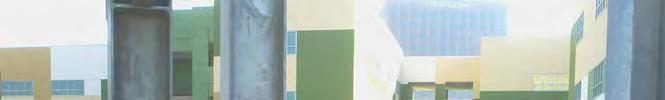
3 Photo 1. West Central Footing Excavation Building Q. Photo Mil HDPE Membrane Installation Building Q. Photo Mil HDPE Extrusion Welding Building Q Footing. Photo Mil Geotextile Covered 60 Mil HDPE Membrane (Building Q Footing Prior to Steel Placement.

. Photo 6.")


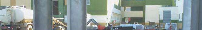
4 Photo 5. Steel Reinforcement Placement (Building Q Footing). Photo 6. Air Injection Piping Building P (East Portion). Photo 7. Sand Dispersion Layer Placement South of Building Q. Photo Mil HDPE Membrane Smoke Test Building P (East Portion)

. Photo 10.")

. Photo 11.")


5 Photo 9. Completed 60-Mil HDPE Membrane Building P (East Portion). Photo inch Sand Layer Atop 60-Mil HDPE Membrane - Building P (East Portion). Photo 11. Protective 100-Mil Geofabric Atop 60-Mil HDPE Building Q Footing. Photo 12. Concrete Pour Atop 60-Mil HDPE Membrane Building Q Footing.


 South")
. 16.")

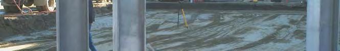
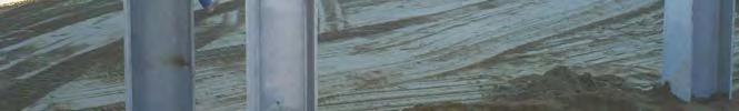
6 13. Sand Dispersion Layer Compaction West of Academy House 3 (Duct Bank) Mil HDPE Membrane Spark Testing Building P Elevator Rooms. 15. Hardscape Passive Vent Gravel Piping (4-inch ADS) South of Building Q (Stairway). 16. Hardscape Vent Trench Gravel Cover Compaction South of Building Q.


7 Mil Geofabric Layer Atop 60-Mil Membrane Vent Trench Cover West of Academy House Mil HDPE Membrane with Air Sweep System Deck Dowels Room P Smoke Test Apparatus P Mil HDPE Membrane 20. Sand Dispersion Layer Placement South of Building Q.

8 21. Hazardous Vent Trench/Pipe Fire Access Road 22. Sand Dispersion Layer South Stairway Canopy Area 23. Liquid Boot Membrane Triple Gym, North Dance Floor Section. 24. Room P-120 HDPE Boot on South Pipe Cluster.
9 Photo 25. Hardscape Vent Trench/Pipe North of Building- P. Photo 26. Hardscape Vent Trench/Pipe Interior NW Corner of Building-P. Photo 27. Sand Mitigation Layer SE of Building-P. Photo Mil HDPE Smoke Test Building P-120
10 Photo 29. Hardscape Vent System Piping SE Courtyard Road. Photo 30. Gravel Compaction Hardscape Vent Trench Road South of Baseball Field. Photo 31. Hardscape Vent Trench/Piping Road West of Basketball Court. Photo oz Geofabric Covering Basketball Court Hardscape Vent Trench.
11 Photo 33. Wall-Behind Compactor used to Consolidate Gravel Atop Basketball Court Vent Trench. Photo 34. Room P-120 Corrugated Metal Deck Air Sweep System. Photo 35. Room P-120 Air Sweep System Metal Deck Cutting. Photo 36. Passive Vent System Lateral - Southwest Basketball Court Vent Riser


12 Photo 37. Concrete Slab Reinforcement Atop Room P-120 Air Sweep System. Photo 38. Hardscape Vent Piping in Gravel Trench North Entrance Road. Photo 39. Hardscape Vent Piping in Gravel Trench Southeast of Building-P. Photo inch Schedule-80 PVC Air Injection Piping Baseball Field South of Blower Pad.


13 Photo 41. Pressure Gauge Central Plant Roof Top Air Blower inch Secdule-80 PVC Vent Lateral to Riser Southeast of Building-P.
14
15 Photo 43. Hardscape Vent System Piping/Trench Main School Entrance Area (Colton Street). Photo 44. Hardscape Vent Trench/Piping Canopy Area (South Side). Photo inch ADS Passive/Vent Piping Basketball Court Area. Photo inch ADS Passive/Vent Piping Basketball Court Area.
16 Photo 47. Worker using walk-behind Compactor to Consolidate Gravel in Basketball Court Passive Vent Trench. Photo inch Schedule 80 PVC Vent Piping to SW Basketball Court Vent Riser. Photo 49. Working Installing Seal/Rain CAP at Vent North School Entrance Passive Gas System Vent. Photo 50. Vent Piping with Moisture Trap Central Plant Gas Sensor Panel.
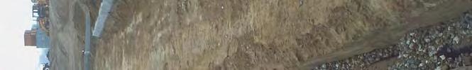
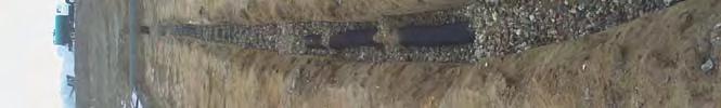
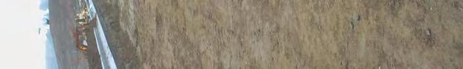
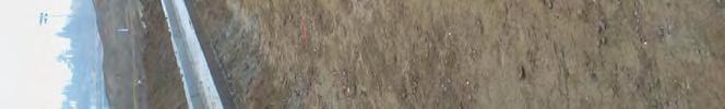
17 PHOTO LOG B (1-188) NUMBER DATE DESCRIPTION 1 12/08/06 Coupon samples were cut and measured from the Liquid Boot sprayed in the Switch Gear Room. There was not adequate thickness in this room; it will need to be sprayed again. 2 04/27/06 The rejected sand on the baseball field being graded as select material for building pad P. 3 05/01/06 The Baseball Field after the rejected sand has been removed. 4 05/25/06 The spark tested geomembrane at footing Q6.4/Q B. 5 05/25/06 Slurry mix being poured into forms to repair footing Q5.3/QH. 6 05/26/06 Geotextile installation at footing Q 3/Q C. 7 05/26/06 Slurry repairs at footing Q6/QF /26/06 Geomembrane installation at footing Q 3/Q C. 9 05/27/06 Cutting out of the geomembrane coupon samples /27/06 Geomembrane coupon sample testing /27/06 Welding of the geomembrane at footing Q5.3/QH 12 05/27/06 A slurry repair at footing Q6.4/QG /27/06 Sand being spread on the baseball field /27/06 Sand on the baseball field being watered /31/06 Sand being dumped on the multipurpose field /01/06 Access road being covered with sand, after it had been scraped /02/06 A smoke test on footing Q 2/Q B /05/06 Sand being placed on the Multipurpose Sportsfield /06/06 Welding of the geomembrane at a footing in Building Q /06/06 A two-inch layer of sand being placed on top of the final layer of geotextile at footing Q6.4/Q8, debris was removed /06/06 The second layer of geotextile being installed at footing Q5.3/QG /06/06 The two inch sand layer in place at footing Q5.3/QJ /06/06 A mud slab being poured at footing Q7.3/QH /07/06 Stockpiling of the sand on the Multipurpose Sportsfield /09/06 Geomembrane was cut away to allow for widening of a footing at location Q7.3/QJ /09/06 Geomembrane start-up welding /09/06 Footing Q3.8/QF.4 in need of repair /12/06 Clay being removed from the large stockpile on the multipurpose field and being placed on the sand dispersion layer, as part of the soil buffer zone /13/06 Sharma, the grading subcontractor, using GPS to survey the soil buffer zone on the Multipurpose 30 06/14/06 A view of the soil buffer zone on top of the sand dispersion layer on the Multipurpose Sportsfield /14/06 Sharma using GPS to survey the landscape area in between Building Q and the existing 32 06/14/06 Plumbing supplies for the gas mitigation system were arriving for the Baseball Field /14/06 The corrugated perforated pipe for the passive venting system at the Baseball Field /15/06 A boring on the Multipurpose Sportsfield, confirming at least 18 inches of soil cover /16/06 Trenching for the gas mitigation piping at the Baseball Field /16/06 Rebar placed on top of the mudslab in a footing in Building Q /19/06 Trenches being dug in the Baseball Field for the air injection piping /19/06 Sand being spread for the sand dispersion layer in the landscape area between Building Q and the existing buildings /19/06 HDPE T-lock being installed on the forms for the exterior footings for Building Q /19/06 Rebar was placed in a footing with the geomembrane system /19/06 Sand being spread in the landscape area between Building Q and the existing buildings /20/06 The air injection piping for the Baseball Field /20/06 The solid north-south leg of the air injection system being installed at the Baseball Field /21/06 A trench on First St. that requires a trench dam /22/06 The air injection pipe on the Baseball Field was covered with a geotextile sock /22/06 The north-south leg of the solid 4-in. SCH 80 PVC pipe on the Baseball Field /26/06 Sand being spread in a landscape area south of the Multipurpose Sportsfield /26/06 Sand being spread in a landscape area along Colton St The sand dispersion layer was hand augered to verify a depth of at least The sand dispersion layer was installed on the slope along Colton St.. 1 of 4
18 Rebar being carefully placed into a lined footing in Building Q HDPE T-Lock installed in the exterior footings at Building Q /30/06 Care was taken to make certain the HDPE T-lock was embedded in the concrete of the exterior footings at Building Q The geomembrane installed at footings in Building Q being spark tested /30/06 The soil buffer zone being installed on the landscape area south of the Multipurpose Sportsfield /05/06 Backfilling the air injection piping in the sand dispersion layer on the Baseball Field I nstallation of the sand dispersion layer on the slope of the landscape area south of the Mutlipurpose Sportsfirle The HDPE T-lock embedded in the concrete footing The passive venting piping being installed at the Baseball Field Sand being delivered and stockpiled on the Multipurpose Sportsfield /10/06 Footing excavations being repaired will slurry in preparation for the instllation of the geomembrane at Building P /10/06 The passive venting system being installed at the Baseball Field HDPE T-lock installed at a footing in Building Q /12/06 The sand dispersion layer being installed on the sloped landscape area south of the Multipurpose Sportsfield HDPE T-lock installed on forms for the exterior footings at Building Q The passive venting piping installed at the Baseball Field The passive venting piping installed at the Baseball Field The first layer of geotextile being installed at footings in Building P Sand being installed in the landscape area between Building Q and the existing buildings HDPE T-lock being installed in an exterior footing at the Central Plant HDPE T-lock being installed at an exterior footing in Building Q The sand dispersion layer being installed at the bottom of the landscape slope area along Colton St A trench requiring a trench dam on Beaudry St Hand augering to verify the thickness of the sand dispersion layer in the landscape area between Building Q and the existing buildings A mud slab being poured at a footing in building P /20/06 The geomembrane in a footing at building P that has been spark tested A trench area on Beaudry St. ready for a trench dam The soil buffer zone was being installed on the sand dispersion layer between Building Q and the existing buildings /21/06 Slurry being poured for trench dams along Beaudry St Slurry being poured for trench dams along Beaudry St /21/06 A completed trench dam on Beaudry St Slurry being poured for a trench dam on First St /21/06 A completed trench dam on First St /27/06 The second layer of geotextile being installed at a footing in Building P The second layer of geotextile installed at a footing in Building P A 2-in. sand layer installed at a footing in Building P /27/06 A mudslab being poured at a footing in Building P /28/06 Rebar installed on top of a mud slab in a footing at Building P HDPE T-lock embedded an exterior footing at Building P /04/06 The sand dispersion layer on the Baseball Field was hand augered using a 50 by 50 grid system to verify a depth of at least The subgrade of the landscape area along the existing buildings was prepared prior to the installation of the sand dispersion layer The subgrade of the landscape area along the existing buildings was surveyed prior to the installation of the sand dispersion layer The soil buffer zone was being installed on the Baseball Field; the soil was spread about a foot thick by a dozer and then scrapers were used to add the additional soil The sand dispersion layer was installed along the existing buildings The sand dispersion layer along Academy House # 4 was installed /09/06 The 3/8 gravel to be used underneath the building slabs for the gas mitigation system /09/06 The subgrade of the landscape area along Academy Houses # 2 and 3 was surveyed prior to the installation of the sand dispersion layer /09/06 HDPE T-lock was installed in Building P /09/06 HDPE geomembrane around the footing in the Freezer Depression area of Building Q was repaired /10/06 The sand dispersion layer along Academy Houses # 2 and 3 was installed /10/06 The trenches for the passive venting piping system in sequences 1 and 2 of Building Q were filled with a 2 gravel base /10/06 The passive venting piping was installed in sequences 1 and 2 of Building Q /10/06 The sand dispersion layer was installed along the Triple Gym and Academy House # 4. 2 of 4
19 104 08/11/06 The sand dispersion layer was installed in the large landscape in between Building Q and the existing buildings /11/06 The passive venting piping was installed on a 2 gravel base in sequence of Building Q /11/06 Pipe sleeve were installed where ever the passive venting piping crossed the footings /14/06 Passive venting piping was held in place during the installation of the gravel layer at Building Q /14/06 The subgrade on a portion of the Multipurpose Sportsfield was surveyed before the sand dispersion layer was installed /15/06 Geomembrane boots were installed on sleeves for piping penetrations in seq. 1of Building Q /15/06 The soil buffer zone being installed on a portion of the Multipurpose Sportsfield /15/06 The air injection piping being installed in seq.1 of Building Q /06/06 Geomembrane was installed for the freezer depression area in Building Q /07/06 The second layer of geotextile was installed for the freezer depression area in Building Q /08/06 Geomembrane boots being installed on conduit penetrations in the electrical area in Building Q /12/06 The air sampling piping being lowered into the gravel layer /13/06 A trench on the Multipurpose Sportsfield that went through the sand dispersion layer /16/06 Geomembrane installation in seq. 1 and 2 of Building Q /16/06 Welding of the geomembrane in seq. 1 and 2 of Building Q /18/06 Spark testing of the geomembrane in seq. 1 of Building Q /19/06 Geomembrane being installed in the electrical area in seq. 2 of Building Q /20/06 Elastuff sealant was applied to boots in Building Q /22/06 Smoke testing of the geomembranr in seq.2 of Building Q /22/06 Smoke coming out of vent riser during the smoke test in seq.2 of Building Q /23/06 Geomembrane being installed in seq. 3 of Building Q /30/06 Trenching for the passive venting piping at Building P /02/06 Smoke testing of seq. 3 of Building Q /03/06 Installation of the sand dispersion layer along the wall at the Baseball Field /05/06 The geomembrane being installed at seq. 4 of building Q /06/06 The geomembrane being smoke tested at Building Q /10/06 Testing of the air sampling piping at Building P /11/06 Testing of the air sampling piping at Building P /11/06 Smoke testing of the geomembrane in seq. 4 of Building Q /16/06 Smoke testing the geomembrane on the south side of Building Q /18/06 The air sampling piping at Building P being wrapped with geotextile and buried in the gravel layer /23/06 The passive venting piping installed at Building P /01/06 The passive venting piping being installed in the Central Plant.eomembrane being installed on the east side of Building P /02/06 The passive venting piping being installed in the Central Plant /03/06 A trench was dug for the installation of a gas mitigation trench dam at the entrance of the Central Plant /06/06 A trench dam being installed near the SW corner of Building Q /06/06 A trench dam being installed near the entrance of the Central Plant /06/06 HDPE Paraseal liner was installed on the retaining walls of Building P East /07/06 The geomembrane at Building P was smoked tested /07/06 The second layer of geotextile was installed on the east side of Building P /08/06 A trench dam was installed on the west side of Building P /09/06 HDPE Paraseal liner was installed on the retaining walls of Building P East /13/06 HDPE Paraseal liner being installed on the retaining walls of Building P East /13/06 The air sampling piping installed in the Central Plant was tested /16/06 The air sampling piping being wrapped with geotextile before being buried in the gravel at the Central Plant /17/06 The geomembrane on the Building P East retaining walls being spark tested /17/06 The bottom layer of geotextile being installed at the Building P Elevator Pit /22/06 The geomembrane in the Central Plant being smoke tested /22/06 Smoke could be seen exiting the vent riser near the entrance of the Central Plant /29/06 The first layer of geoemembrane being installed at the Building P Elevator Pit /30/06 The first layer of geomembrane being installed in the Building P Elevator Pit /04/06 The second layer of geomembrane being installed at the Building P Elevator Pit /06/06 Elastuff was poured into the bracket installed around the closely spaced conduits in the Switch Gear Room. 3 of 4
20 157 12/07/06 A geotextile was installed in the Switch Gear Room. The Liquid Boot will be sprayed directly on top of this geotextile /07/06 Liquid Boot being sprayed in the Switch Gear Room /07/06 The second layer of geomembrane being installed at the Building P - Elevator Pit /08/06 Coupon samples were cut and measured from the Liquid Boot sprayed in the Switch Gear Room. There was not adequate thickness in this room; it will need to be sprayed again /12/06 Batten bar as well as a second layer of geotextile were installed on the chiller valve vault on the west side of Building P /15/06 The passive venting piping system for Building Q was smoke tested after the slab was poured. Smoke was injected at vent riser VRQ-4 and could be seen exiting all of the others /15/06 Smoke was observed flowing out of vent riser VRQ /15/06 The passive venting piping system for the Central Plant was smoke tested after the slab was poured. Smoke was injected at vent riser VRC /15/06 Smoke was observed flowing out of vent riser VRC /15/06 The passive venting piping system for Building P - West was smoke tested after the slab was poured. Smoke was injected at vent riser VRP /15/06 Smoke was observed flowing out of vent riser VRP /18/06 The Liquid Boot system in the Switch Gear Room was smoke tested using a smoke machine and a ShopVac /18/06 Coupons were cut from the Liquid Boot system in the Switch Gear Room to verify the thickness of the application /19/06 Geotextile was installed on the floor of the Switch Gear Room after the Liquid Boot had cured /22/06 The air sampling piping being wrapped with a geotextile before being buried in the 3 sand layer /09/07 Gravel was installed in the DWP Vault and the 3 thickness was determined by using a laser to shoot the before and after elevations /18/07 Batten bar being installed along the west and north walls of the DWP Vault /22/07 Elastuff was poured into the booted pipes that were around the ground wire penetrations in the DWP Vault to make a seal /23/07 The geomembrane being welded in the DWP Vault /24/07 Stainless steel clamps were installed on the piping penetrations in the DWP Vault /24/07 The DWP Vault was smoke tested and smoke was seen coming from in between the strands of the ground wires /25/07 The ground wires in the DWP Vault were Cadwelded to make a section of the wire solid and the Elastuff will be extended past this solid section to make a seal. Welding blankets and plywood were used to protect the geomembrane from the hot materials /25/07 A ground wire that was Cadwelded /26/07 The geomembrane system in the DWP Vault being smoke tested /26/07 The flowrate of a ShopVac was adjusted and the air sampling piping was tested for the DWP Vault /26/07 The geomembrane system in the DWP Vault was smoke tested again /26/07 The Cadwelded wire and the repaired geomembrane in the DWP Vault were smoke tested again and there was no leaks /26/07 The patch for the smoke injection point in the DWP Vault being spark tested /11/07 Geomembrane being installed in the Triple Gym /12/07 The geomembrane being smoke tested in the Triple Gym /24/07 Geomembrane boots being installed on piping penetrations in the Triple Gym /26/07 Passive venting piping being installed in the parking structure. 4 of 4


21 Photo The rejected sand being used as a select material for building pad Q. Photo The rejected sand on the baseball field being graded as select material for building pad P. Photo The Baseball Field after the rejected sand has been removed Photo The spark tested geomembrane at footing Q6.4/Q B.
22 Photo Slurry mix being poured into forms to repair footing Q5.3/QH. Photo Geotextile installation at footing Q 3/Q C. Photo Slurry repairs at footing Q6/QF.1. Photo Geomembrane installation at footing Q 3/Q C.
23 Photo Cutting out of the geomembrane coupon samples Photo Geomembrane coupon sample testing. Photo Welding of the geomembrane at footing Q5.3/QH Photo A slurry repair at footing Q6.4/QG.
24 Photo Sand being spread on the baseball field. Photo Sand on the baseball field being watered. Photo Sand being dumped on the multipurpose field Photo Access road being covered with sand, after it had been scraped.
25 Photo A smoke test on footing Q 2/Q B. Photo Sand being placed on the Multipurpose Sportsfield. Photo Welding of the geomembrane at a footing in Building Q Photo A two-inch layer of sand being placed on top of the final layer of geotextile at footing Q6.4/Q8, debris was removed.
26 Photo The second layer of geotextile being installed at footing Q5 3/QG Photo The two inch sand layer in place at footing Q5.3/QJ. Photo A mud slab being poured at footing Q7 3/QH Photo Stockpiling of the sand on the Multipurpose Sportsfield.
27 Photo Geomembrane was cut away to allow for widening of a footing at location Q7.3/QJ.3. Photo Geomembrane start-up welding. Photo Footing Q3.8/QF.4 in need of repair. Photo Clay being removed from the large stockpile on the multipurpose field and being placed on the sand dispersion layer, as part of the soil buffer zone.
28 Photo Sharma, the grading subcontractor, using GPS to survey the soil buffer zone on the Multipurpose Sportsfield. Photo A view of the soil buffer zone on top of the sand dispersion layer on the Multipurpose Sportsfield. Photo Sharma using GPS to survey the landscape area in between Building Q and the existing buildings in preparation for sand placement. Photo Plumbing supplies for the gas mitigation system were arriving for the Baseball Field.
29 Photo The corrugated perforated pipe for the passive venting system at the Baseball Field. Photo A boring on the Multipurpose Sportsfield, confirming at least 18 inches of soil cover. Photo Trenching for the gas mitigation piping at the Baseball Field. Photo Rebar placed on top of the mudslab in a footing in Building Q.
30 Photo Trenches being dug in the Baseball Field for the air injection piping. Photo Sand being spread for the sand dispersion layer in the landscape area between Building Q and the existing buildings. Photo HDPE T-lock being installed on the forms for the exterior footings for Building Q. Photo Rebar was placed in a footing with the geomembrane system.
GEOMEMBRANE FIELD INSTALLATION
 GEOMEMBRANE FIELD INSTALLATION CONTENTS Introduction Quality Control and Quality Assurance Types of lining systems Basic Lining Design Executive Lining Design Basic Lining Design Specification Executive
LANDFILL FINAL COVER AND MANAGEMENT OF LEACHATE SEEPS BELOW FINAL COVER
 LANDFILL FINAL COVER AND MANAGEMENT OF LEACHATE SEEPS BELOW FINAL COVER Ali Khatami, Ph.D., P.E. SCS Engineers 1900 NW Corporate Blvd. #W110 Boca Raton, Florida 33431 akhatami@scsengineers.com Abstract:
SECTION EARTHWORK
 SECTION 02200 - EARTHWORK PART 1 GENERAL 1.1 SECTION INCLUDES A. Grading and Excavation B. Trenching C. Bedding D. Backfill and Compaction (New and Native) E. Aggregate Material F. Geotextile Fabric PART
This is intended to provide uniform application of the codes by the plan check staff and to help the public apply the codes correctly.
 SUPPLEMENTAL CORRECTION SHEET FOR METHANE MITIGATION SYSTEMS - ELECTRICAL This is intended to provide uniform application of the codes by the plan check staff and to help the public apply the codes correctly.
SWANA/A&WMA s. Third Annual Landfill Operator s Training Geosynthetics in Landfills. February 13, 2013
 SWANA/A&WMA s Third Annual Landfill Operator s Training Geosynthetics in Landfills February 13, 2013 Geosynthetics Products Applications Current Lining Requirements Tips 2 Geosynthetics polymeric products
 3" TO 4" OF TOPSOIL 2:1 MIRAFI HP 565 GEO FABRIC OR EQUIVALENT 9' SPILLWAY EL=7147 2:1 SPILLWAY SECTION N.T.S. TOP OF POND EL=7149' RIP-RAP D 50 8" WRAPPED IN FILTER FABRIC 45 MIL HDPE POND LINER OR EQUIVALENT
Construction and Installation Instructions For the A&A Splash Pad
 Construction and Installation Instructions For the A&A Splash Pad Revised 9//09 These instructions are not meant to be detailed construction plans since you will be using your standard plumbing and deck
POND SEALING OR LINING GEOMEMBRANE OR GEOSYNTHETIC CLAY LINER
 NATURAL RESOURCES CONSERVATION SERVICE CONSERVATION PRACTICE STANDARD POND SEALING OR LINING GEOMEMBRANE OR GEOSYNTHETIC CLAY LINER CODE 521 (NO.) DEFINITION A liner for an impoundment constructed using
6. Detail drawings. 1. Lap Splices 2. Corners 3. Penetrations 4. Terminations 5. Anchoring 6. Membrane cover
 6. Detail drawings 1. Lap Splices 2. Corners 3. Penetrations 4. Terminations 5. Anchoring 6. Membrane cover General technical guide for water reservoirs 87 6.1. Lap Splices Geo-E-LS-1 Standard Seam using
Acronyms. TRI TRI Environmental, Inc. Table of Contents. iii
 Table of Contents Acronyms AEG American Environmental Group, Ltd. AMEC American Environmental & Infrastructure, Inc. CAT I Category I CES ARCADIS Construction and Environmental Services Group CQA Construction
SPL-2.2 MECHANICALS POOL LAWN. 3rd FLOOR TERRACES AMENITY RESTAURANT 230 EAST AVENUE AMENITY NORWALK, CT
 8 8 CONCRETE RAMP WOOD STEPS SWIMMING POOL 8 METAL POOL ENCLOSURE FENCE 9 SINGLE LEAF METAL GATE 0 LAWN HANGING CANOPY WITH DOWN LIGHTS METAL & GLASS AWNING AMENITY ROOM WITH FOLDING GLASS WALLS CONCRETE
HILCORP ALASKA, LLC HAPPY VALLEY MIDDLE NATURAL GAS EXPLORATION PROJECT DEEP CREEK UNIT BOUNDARY PROPOSED ACCESS ROAD T02S T03S R14W
 , LLC STERLING HWY. M.P. 142.8 28 33 TIM AVE. DEEP CREEK UNIT BOUNDARY 27 26 25 TIM AVE. CULVERT REPLACEMENT PROPOSED ACCESS ROAD 34 35 36 T2S T3S 31 NINILCHIK, ALASKA 5 4 3 2 BEGIN ROAD CONSTRUCTION 1
SITE PREPARATION GRADING
 17 SITE PREPARATION GRADING Objectives 1. Be able to describe and explain why grading is done in the landscape. 2. Be able to define and summarize how cutting and filling affect plant growth. 3. Be able
Pondless Waterfall Vault
 Pondless Waterfall Vault Installation Instructions & Owner s Manual Step-by-Step Installation Instructions for the Pondless Waterfall Vault Congratulations on the purchase of the AquascapePRO Pondless
SILT FENCE MACHINE SLICED ERO-1A STEEL FENCE POST (T-POST), MINIMUM 5' LONG, 6' MAXIMUM SPACING.
, MINIMUM 5' LONG, 6' MAXIMUM SPACING.") STEEL FENCE POST (T-POST), MINIMUM 5' LONG, 6' MAXIMUM SPACING. ATTACH FABRIC TO POSTS WITH MINIMUM 3 ZIP TIES (50 LB. TENSILE) PER POST IN TOP 8" OF FABRIC. MONOFILAMENT GEOTEXTILE FABRIC PER MNDOT TABLE
STEEL FENCE POST (T-POST), MINIMUM 5' LONG, 6' MAXIMUM SPACING. ATTACH FABRIC TO POSTS WITH MINIMUM 3 ZIP TIES (50 LB. TENSILE) PER POST IN TOP 8" OF FABRIC. MONOFILAMENT GEOTEXTILE FABRIC PER MNDOT TABLE
INSTALLATION GUIDELINES FOR GEOTEXTILES USED IN FILTRATION AND DRAINAGE APPLICATIONS
 INSTALLATION GUIDELINES FOR GEOTEXTILES USED IN FILTRATION AND DRAINAGE APPLICATIONS Prepared by TenCate Geosynthetics North America 365 South Holland Drive Pendergrass, GA 30567 Tel: (706) 693-2226 Fax:
CONSTRUCTION DRAWINGS MODULE 6 LINER SYSTEM MONTEREY PENINSULA LANDFILL
 CONSTRUCTION S R SYSTEM VICINITY MAP B- GEOTECHINCAL BORING LOCATION G- MONITORING WELL LOCATION GP-6A LANDFILL GAS PROBE LOCATION POINT LOCATION MAP DESCRIPTION SHEET EISTING CONDITIONS ECAVATION GRADES
Geosynthetics and Their Applications
 GEOSYNTHETICS AND REINFORCED SOIL STRUCTURES Different Types of Geosynthetics and Their Applications K. Rajagopal, Professor Department of Civil Engineering IIT Madras, Chennai e-mail: gopalkr@iitm.ac.inac
!!!!!!!!!!!!!!!! INSTALLATION!GUIDELINES!MANUAL! January!2018,!Revision!3.0! Advanced!Revetment!Technology!
 INSTALLATIONGUIDELINESMANUAL January2018,Revision3.0 Beforeutilizingthisdocumentas aninstallationtool,installers shoulddownloadthelatestversion oftheinstallationguidelines Manualfromthetechnical downloadssectionofourwebsite
CITY OF BREA COMBUSTIBLE SOIL-GAS GUIDELINE Updated
 PURPOSE CITY OF BREA COMBUSTIBLE SOIL-GAS GUIDELINE Updated 1-2017 Combustible soil-gases, such as methane, can seep into structures and explode if a source of ignition is present when gases accumulate
Tree Pits Construction Guide
 Tree Pits Construction Guide What are tree pits? Tree pits collect stormwater runoff from small carpark areas or roads. Runoff filters through the tree roots and surrounding soil mix, trapping sediment
Urban Conservation Practice Physical Effects ESTABLISHMENT, GROWTH, AND HARVEST NUTRIENT MANAGEMENT
 NOT WELL 800 - Urban Stormwater Wetlands A constructed system of shallow pools that create growing conditions for wetland plants to lessen the impacts of stormwater quality and quantity in urban areas.
SPECIAL SPECIFICATION 3687 Impermeable Liner
 1993 Specifications CSJ s 0569-01-043 & 0945-04-025 SPECIAL SPECIFICATION 3687 Impermeable Liner 1. Description. This Item shall govern for the furnishing and installation of the impermeable liner (geomembrane)
Analyzing the Bioretention Construction Sequence
 Analyzing the Bioretention Construction Sequence Avoiding future problems through careful installation procedures, construction inspection and first year maintenance 20 Steps to Better Bioretention Step
GUIDANCE FOR SOIL GAS MANAGEMENT SYSTEM PROPOSED CITY OF VANCOUVER BY-LAW IMPOUND LOT 425 INDUSTRIAL AVENUE, VANCOUVER, BC
 E/09/0265 February 6, 2009 06-1412-084/6200 City of Vancouver Projects Branch, Engineering Services 453 West 12th Avenue Vancouver, BC V5Y 1V4 Attention: Mr. Mark Schwark, P.Eng. RE: GUIDANCE FOR SOIL
BANK UNDERDRAIN (ALTERNATE LOCATION) (PIPE SHALL BE WRAPPED WITH GEOTEXTILE) DRAINAGE LAYER GRANULAR MATERIAL CLASS II 3" NOMINAL DEPTH
 (PIPE SHALL BE WRAPPED WITH GEOTEXTILE) DRAINAGE LAYER GRANULAR MATERIAL CLASS II 3 NOMINAL DEPTH") NATURAL GROUND WITH SEEPAGE LAYERS AND / OR PERVIOUS SOIL CAP MATERIAL FOR "GRANULAR BLANKET" SHALL BE GRANULAR MATERIAL CLASS II SOD AND TOPSOIL OR TOPSOIL, SEED, AND MULCH AS SPECIFIED ON PLANS CLASSED
NATURAL GROUND WITH SEEPAGE LAYERS AND / OR PERVIOUS SOIL CAP MATERIAL FOR "GRANULAR BLANKET" SHALL BE GRANULAR MATERIAL CLASS II SOD AND TOPSOIL OR TOPSOIL, SEED, AND MULCH AS SPECIFIED ON PLANS CLASSED
SUSTAINABLE REDEVLOPMENT OF FORMER AND ABANDONED LANDFILLS LESSONS FROM PRACTICE
 Sardinia 2007 11 th International Waste Management and Landfilling Symposium Cagliari, Italy, 3 October 2007 SUSTAINABLE REDEVLOPMENT OF FORMER AND ABANDONED LANDFILLS LESSONS FROM PRACTICE Edward Kavazanjian,
2018 Annual Landfill Inspection Report
 2018 Annual Landfill Inspection Report Landfill H.W. Pirkey Plant Southwestern Electric Power Company Hallsville, Texas December 17, 2018 Prepared for: Southwestern Electric Power Company H.W. Pirkey Plant
Consulting Engineers and Scientists. Closure Plan. Submitted by: GEI Consultants, Inc Voyager Drive Green Bay, Wisconsin
 Consulting Engineers and Scientists Regulation Compliance Report Submitted to: We Energies 333 West Everett Street, A231 Milwaukee, Wisconsin 53203 Submitted by: GEI Consultants, Inc. 3159 Voyager Drive
A Collection and Removal System for Water in the Final Cover Drainage Layer
 Landfills A Collection and Removal System for Water in the Final Cover Drainage Layer A rainwater toe drainage system, by removing water from the final cover drainage layer, eliminates the possibility
D.P.E. Enviroliner. geotextile protection layer. covering new ground 2016
 LEVEL 7 osynthetic clay liner www.gundle.co.za H.D.P.E. Enviroliner geosynthetic clay liner geotextile protection layer D.P.E. Enviroliner solid waste sand (leachate collection) geotextile protection layer
Technical Specification Guidelines
 SECTION I- DESIGN CONSIDERATIONS PAGE 1.01 APPLICABILITY...I.2 1.02 PROTECTION AND PRECAUTIONS...I.3 1.03 SITE AND SUBSTRATE CONSIDERATIONS...I.3 1.04 PRODUCT CONSIDERATIONS...I.8 1.05 FASTENING CONSIDERATIONS...I.9
1993 Specifications CSJ SPECIAL SPECIFICATION ITEM Impermeable Liner
 1993 Specifications CSJ 0128-01-085 SPECIAL SPECIFICATION ITEM 5327 Impermeable Liner 1. Description. This Item shall govern for the furnishing and installation of the impermeable liner (geomembrane) shown
A. Install all temporary erosion control measures (in accordance with MNDOT General Conditions 2573) prior to site disturbance.
 prior to site disturbance.") The language provided in these specifications is meant to serve as a reminder and provide a generic example of the type of language that should be provided in final construction documents. This language
The language provided in these specifications is meant to serve as a reminder and provide a generic example of the type of language that should be provided in final construction documents. This language
Low Flow Rates Low Filtration Sandy Soils Medium Flow Rates Medium Filtration Clayey Soils [1] High Flow Rates High Filtration Polluted Soils
![Low Flow Rates Low Filtration Sandy Soils Medium Flow Rates Medium Filtration Clayey Soils [1] High Flow Rates High Filtration Polluted Soils](/thumbs/82/86978219.jpg "Low Flow Rates Low Filtration Sandy Soils Medium Flow Rates Medium Filtration Clayey Soils [1] High Flow Rates High Filtration Polluted Soils") Filter Ponds DE-WATERING SEDIMENT CONTROL TECHNIQUE Low Flow Rates Low Filtration Sandy Soils Medium Flow Rates Medium Filtration Clayey Soils [1] High Flow Rates High Filtration Polluted Soils [1] Capture
Filter Ponds DE-WATERING SEDIMENT CONTROL TECHNIQUE Low Flow Rates Low Filtration Sandy Soils Medium Flow Rates Medium Filtration Clayey Soils [1] High Flow Rates High Filtration Polluted Soils [1] Capture
Cedar Niles Future Park Site Wetland #1
 Date: October 20, 2014 Site: Landowner: Johnson County Parks Designer: Thomas R. Biebighauser Individuals Present: Thomas R. Biebighauser, Dr. Eliodora Chamberlain (US EPA), Jason Daniels (US EPA), Jeannette
Up By Roots Healthy Soils and Trees in the Built Environment
 Up By Roots Healthy Soils and Trees in the Built Environment 2009 ASLA Honor Award James Urban, FASLA, ISA Urban Tree + Soils Annapolis, Maryland Practical Applications Preserving, repairing, and replacing
SECTION SOIL BIOENGINEERING OR SHORELINE STABILIZATION
 SECTION 32 93 43 SOIL BIOENGINEERING OR SHORELINE STABILIZATION PART 1 GENERAL 1.01 SECTION INCLUDES A. CONTRACTOR shall furnish all labor, materials, supplies, equipment, tools and transportation; perform
FIGURE 1 Crews finalizing 60-mil (1.5-mil), five-ply CSPE geomembrane liner with cap strips over field seams at the Palos Verdes Reservoir
, five-ply CSPE geomembrane liner with cap strips over field seams at the Palos Verdes Reservoir") FIGURE 1 Crews finalizing 60-mil (1.5-mil), five-ply CSPE geomembrane liner with cap strips over field seams at the Palos Verdes Reservoir EDITOR S NOTE Part 1 of Reviving the Palos Verdes Reservoir appeared
FIGURE 1 Crews finalizing 60-mil (1.5-mil), five-ply CSPE geomembrane liner with cap strips over field seams at the Palos Verdes Reservoir EDITOR S NOTE Part 1 of Reviving the Palos Verdes Reservoir appeared
Appendices: Glossary. General Terms. Specific Terms. Low Impact Development Approaches Handbook
 67 67 General Terms Specific Terms 66 Low Impact Development Approaches Handbook The vocabulary of low impact development is evolving, and many terms are used interchangeably and to describe the same or
AquaBlox Water Matrix
 quablox Water Matrix Installation Instructions & Owner s Manual Step-by-step installation Instructions for the following quablox Water Matrix pplications: { Pondless Waterfalls { RainXchange Rainwater
Geosynthetics: GEOTEXTILES ASDSO WOVEN GEOTEXTILE GEOSYNTHETICS IN DAMS. Geosynthetics in Dams, Forty Years of Experience by J.P.
 ASDSO ORLANDO, SEPTEMBER 2005 GEOSYNTHETICS IN DAMS FORTY YEARS OF EXPERIENCE J.P. GIROUD Geosynthetics: GEOMEMBRANES GEOTEXTILES GEOMATS GEONETS GEOCOMPOSITES GEOGRIDS etc. GEOMEMBRANES GEOTEXTILES Used
Overview of Canal Lining Projects. Montana Association of Dam and Canal Systems October 5 and 6, Jack Haynes EDC Canal Linings, LLC Owner
 Overview of Canal Lining Projects Montana Association of Dam and Canal Systems October 5 and 6, 2011 Jack Haynes EDC Canal Linings, LLC Owner Scope of Study 34 Test Sections installed 18 Exposed Geomembranes
The use of geosynthetics in the installation of ballast layers
 The use of geosynthetics in the installation of ballast layers C. Cilliers, Jones & Wagener (Pty) Ltd, South Africa, cilliers@jaws.co.za ABSTRACT The ballast layer is an essential element of any landfill
AQUAMASTER INSTALLATION GUIDE
 AQUAMASTER INSTALLATION GUIDE PROUD MEMBER Geosynthetic Materials Association PROUD MEMBER Industrial Fabrics Association International TABLE OF CONTENTS 1. GENERAL...1 1.1. Scope...1 1.2. Applications...1
Piles, Trenching, Inverters, Cables, Material Deliveries
 Agricultural Inspection Report General Information Project Name Albany Date of Inspection 20161012 Start/End Time 7:50 am Inspector s Name(s) Inspector s Title(s) Describe present phase of construction
UNIFIED FACILITIES GUIDE SPECIFICATIONS
 USACE / NAVFAC / AFCEC / NASA UFGS-02 66 00 (February 2010) ----------------------------- Preparing Activity: USACE Superseding UFGS-02 66 00 (April 2006) UNIFIED FACILITIES GUIDE SPECIFICATIONS References
Alternative Cover Systems
 Alternative Cover Systems RemTech 2017 October 13, 2017 Outline Capping solutions Why use alternate cover systems Exposed geomembrane cap systems Geosynthetic Turf cap systems What is it? How is it installed?
THE FACTOR 9 HOME: A NEW PRAIRIE APPROACH
 1 2 3 4 5 6 7 8 9 10 ABSTRACT THE FACTOR 9 HOME: A NEW PRAIRIE APPROACH Robert Dumont and Tara Morin Building Performance Business Unit, Saskatchewan Research Council 15 Innovation Boulevard, Saskatoon,
BREWSTER SR173 PROPOSED: OKANOGAN RIVER PADDLERS CAMPGROUND WATERBODY: OKANOGAN RIVER NEAR: BREWSTER COUNTY: OKANOGAN STATE: WASHINGTON
 OKANOGAN RIVER PROJECT LOCATION SR53 COLUMBIA RIVER SR73 METHOW RIVER PATEROS SR7 SR7 BRIDGEPORT VICINITY MAP NEAR: VICINITY 2 GEBBERS FARMS INC APN 302570024 STATE HWY 7 DOUGLAS CO. PUD NO. APN 302570037
Final Report: Appendix G. LID Driveway Retrofit and Teaching Tool at Bristol County Agricultural High School, Dighton - Supporting Information
 Bridgewater State University Virtual Commons - Bridgewater State University Phase II Final Report Taunton River Watershed Project 2011 Final Report: Appendix G. LID Driveway Retrofit and Teaching Tool
Engineering Report: Appendix F Volume 3 Landfill Liner Construction Specifications COWLITZ COUNTY HEADQUARTERS LANDFILL PROJECT COWLITZ COUNTY, WASHIN
 Engineering Report: Appendix F Volume 3 Landfill Liner Construction Specifications COWLITZ COUNTY HEADQUARTERS LANDFILL PROJECT COWLITZ COUNTY, WASHINGTON TECHNICAL SPECIFICATIONS GENERIC CELL CONSTRUCTION
Leak Location Geosynthetic Materials in Base Liner Systems. NY Federation SWANA. May, 2014
 Leak Location Geosynthetic Materials in Base Liner Systems NY Federation SWANA May, 2014 Different ELI Surveys A. Covered Electrical Liner Integrity (ELI) Survey Dipole Method Suitable for water or soil
General Information. Site Conditions. 9b 9b. 9a 1b. Best Management Practices Illustration
 Model Construction SWPPP Planning & Development Services 1800 Continental Place Mount Vernon WA 98273 voice 360-416-1320 inspections 360-416-1330 www.skagitcounty.net/stormwaterpermitting Permit #: General
Butyl Products Ltd. Pond Guide
 Butyl Products Ltd. Pond Guide Page 2 BUTYL PRODUCTS LIMITED For beautiful garden pools.. Butyl Products Pond Liner division has been manufacturing Butyl pond liners for over 35 years, and is the longest
INTERNATIONAL ASSOCIATION OF GEOSYNTHETICS INSTALLERS (IAGI) AND FABRICATED GEOMEMBRANE INSTITUTE (FGI)
 AND FABRICATED GEOMEMBRANE INSTITUTE (FGI)") INTERNATIONAL ASSOCIATION OF GEOSYNTHETICS INSTALLERS (IAGI) AND FABRICATED GEOMEMBRANE INSTITUTE (FGI) GUIDELINES FOR INSTALLATION OF: FACTORY FABRICATED LIGHTWEIGHT (
INTERNATIONAL ASSOCIATION OF GEOSYNTHETICS INSTALLERS (IAGI) AND FABRICATED GEOMEMBRANE INSTITUTE (FGI) GUIDELINES FOR INSTALLATION OF: FACTORY FABRICATED LIGHTWEIGHT (
SECTION 2.5. Construction Quality Assurance Plan
 SECTION 2.5 Construction Quality Assurance Plan Table of Contents 1.0 Purpose and Scope... 1-1 1.1 Purpose... 1-1 1.2 Scope... 1-1 2.0 Operator and CQA Roles, Responsibilities, and Qualification... 2-1
Test Pit Observation Report. Albertville Business Park 67th Street to 70th Street NE Albertville, Minnesota. Prepared for.
 Test Pit Observation Report Albertville Business Park 67th Street to 70th Street NE Albertville, Minnesota Prepared for Fehn Companies Professional Certification: I hereby certify that this plan, specification,
Stormwater protection
 70 70 Visqueen High Performance Urban Drainage Geomembrane 70 Visqueen GX Geomembrane UDG 73 Hanson Aquaflow SC Membrane Stormwater protection A fully integrated stormwater management system provides relief
Silva Cell 2 Installation Guidelines
 Silva Cell 2 Installation Guidelines Silva Cell 2 components Deck 1X post 3X post 2X post Base 1 Base (bottom piece) 2 Posts 1X 2X 3X (1x + 2X) 3 1X assembled 16.7 (424 mm) 4 2X assembled 30.9 (784 mm)
I N D U S T R I A L Y A R D S
 I N D U S T R I A L Y A R D S GEOTEXTILES INDUSTRIAL YARDS 1.0 Features of INDUSTRIAL PG 2 YARDS 2.0 How Typar geotextiles PG 2 work 4.0 Installation guide PG 7 5.0 Overlap and joining PG 8 6.0 Setting
The following general requirements will be met for all planter box installations:
 Greenville County Technical Specification for: WQ-25 PLANTER BOX 1.0 Planter Box 1.1 Description Planter boxes are designed to capture and temporarily store stormwater runoff. Planter Boxes are intended
Installation and Maintenance Instructions
 Commercial & Industrial Positive Pressure or Condensing AL 29-4C Stainless Steel High Challenge Special Gas Vent Also for Natural Draft Appliances 3",4",5",6",7",8",9",10" and 12" Diameter Special Gas
Low Impact Development Practices
 Low Impact Development Practices Michael Dietz, Ph.D. CT Nonpoint Education for Municipal Officials (NEMO) Center for Land Use Education and Research May 8, 2013 Town of Bolton Planning and Zoning Commission
EROSION & SEDIMENT CONTROL
 EROSION & SEDIMENT CONTROL Surface Water Protection During Well Site Construction Kelly Kees, PE WVDEP, Office of Oil and Gas SEDIMENT & EROSION CONTROL PLANS Per West Virginia State Code 22-6-6(d) 22-6A-7(c),
Capillary Action Subsurface Irrigation
 Sandy Soil Layer-Green Pavement Irrigation and Drainage Grass Grid Green Pavement Grass Grid Growing Medium Geotextile Capillary Action Subsurface Irrigation Graded Gravel Geotextile WCID-Water Conservation,
Nondestructive Testing of Geomembranes
 From NDT Technician, Vol. 11, No. 2, pp: 1 5. Copyright 2012 The American Society for Nondestructive Testing, Inc. The American Society for Nondestructive Testing www.asnt.org FOCUS Nondestructive Testing
LET S GET IT DONE STORMWATER MANAGEMENT
 LET S GET IT DONE STORMWATER MANAGEMENT STORMWATER MANAGEMENT R-Tank stormwater systems provide underground storage of stormwater. After a rain event fills the R-Tank, stormwater can flow into the drainage
Subsurface Infiltration Bed
 Subsurface Infiltration Bed The Subsurface Infiltration Bed BMP consists of a storage bed underlying either a vegetated or hardscaped surface for the purpose of temporary storage and infiltration of stormwater
5/15/2013. Basin Area. Vegetation. Rainfall & Runoff. Soil Type. Topics. Factors Influencing Erosion. Factors Influencing Erosion
 Topics Erosion, TESC and Construction sequencing Procedures and timing Remedies for failing sites Curtis Hinman WSU Extension and Bio Systems Eng. Faculty Low Impact Development Specialist chinman@wsu.edu
APPLICATIONS IN FILTRATION AND DRAINAGE & EROSION CONTROL
 Lecture 36 APPLICATIONS IN FILTRATION AND DRAINAGE & EROSION CONTROL Prof. G L Sivakumar Babu Department of Civil Engineering Indian Institute of Science Bangalore 560012 Geotextile filter requirements:
Brick Paver Installation Guide
 Brick Paver Installation Guide Jacksonville, FL 5050 ELINOR ROAD JACKSONVILLE, FL 32257 904.296.7777 Orange Park, FL 71 COLLEGE DRIVE ORANGE PARK, FL 32065 904.458.0150 EnhanceCompanies.com Tools Needed
Aquaculture Lining Systems
 Aquaculture Lining Systems The world relies on Infabsol Geomembranes Industrial Fabric Solutions Geomembranes Improve Your Profit Margins Ponds and tanks used for fish and shrimp farming can be greatly
Illinois Urban Manual
 Illinois Urban Manual Jim Nelson: Association of Illinois Soil and Water Conservation Districts (AISWCD) Funding for this project provided, in part, by the Grand Victoria Foundation of Elgin IL, the Governor
TERREWALKS Installation Manual
 TERREWALKS Installation Manual Overview 2 1 2 3 4 5 6 7 8 9 10 1) Break out existing concrete (use jackhammers near trees) and clean out loose soil 2) Conduct tree root inspection (if applicable) 3) If
INSTALLATION QUALITY-ASSURANCE GUIDE FOR SOLMAX-GSE S CONDUCTIVE LINER
 INSTALLATION QUALITY-ASSURANCE GUIDE FOR SOLMAX-GSE S CONDUCTIVE LINER These instructions present some general guidelines for installing and surveying Solmax-GSE s smooth edged conductive backed geomembranes
900 N. Via Piemonte Ontario, CA
 2 3 L 8 5'-0" 6'-1" 5'-0" 4'-0" 2'-0" D.5 6" 9'-9" K 2 1 2 " 5'-0" 2'-0" 1'-2" 8" 4 4.3 7'-0" C.6 1'-8 1 2 " 7'-0" 8" 10'-6" 5'-0" 8" 6" 6'-6" 6'-3" PLUMBING SCOPE OF WORK - DRAINS 7'-3" 6'-8" KEC TO PROVIDE:
WH101F & WR101F Typical Installation Instructions & Warranty Information. Simplex Station
 WH101F & WR101F Typical Installation Instructions & Warranty Information Simplex Station 1 Environment One Grinder Pump Feature Identification 1. Grinder Pump Basin High density polyethylene (HDPE) 2.
Case Study Bioretention Installation and Maintenance
 Case Study Bioretention Installation and Maintenance Bioretention Crime Scene Investigation A reality TV series where you get to watch disturbing bioretention crimes and use advanced forensics to solve
Stormwater and Your Home. Mason Conservation District. Stephanie Bishop, Environmental Specialist Rich Geiger, P.E., District Engineer
 Stormwater and Your Home Mason Conservation District Stephanie Bishop, Environmental Specialist Rich Geiger, P.E., District Engineer This workshop is sponsored by Mason County Public Works & funded by
1. RETAINING WALL SELECTION PROCEDURE
 1. RETAINING WALL SELECTION PROCEDURE a. Select the appropriate design table(s) depending on whether or not there are fences located above the retaining wall. Go to Section 3.1 or 4.1 of this document
Feet. Overland. Drainage Area Boundary. To Swale. Swale. To Catch Basin. Culvert Pipe. To Drain Outfall. NRCS Soil Area Boundary
 0 25 50 00 Feet Parcel Boundary, Approximate 202 LIDAR 2 FT CONTOURS, VCGI BING AERIAL NRCS SOIL MAPPING MMI FIELD DATA Culvert Pipe Swale 0 Scale: "=40' SOURCE(S): NRCS Soil Area Boundary Overland st
POND Construction. Perry L. Oakes, PE State Conservation Engineer Natural Resources Conservation Service
 POND Construction Perry L. Oakes, PE State Conservation Engineer Natural Resources Conservation Service DdY Did You Know? Alabama is the only state without any safe dams legislation. Alabama has a very
Cost Estimating for Landfill Design
 Cost Estimating for Landfill Design Presentation at ASTSWMO Portland, Oregon Meeting August 14, 2007 Robert Maxey, P.E. EPA Office of Solid Waste Corrective Action Programs Branch maxey.bob@epa.gov Landfill
Illinois Emergency Management Agency
 Illinois Emergency Management Agency Radon in Construction Patrick Daniels & Melinda Lewis 1 What is Radon? Radon is an indoor air pollutant. Radon is a colorless, odorless radioactive gas that comes from
CONSTRUCTION SPECIFICATION FOR RIP RAP, ROCK PROTECTION AND GRAVEL SHEETING
 ONTARIO PROVINCIAL STANDARD SPECIFICATION METRIC OPSS 511 FEBRUARY 1990 CONSTRUCTION SPECIFICATION FOR RIP RAP, ROCK PROTECTION AND GRAVEL SHEETING 511.01 SCOPE 511.02 REFERENCES 511.03 DEFINITIONS 511.04
GREEN LOO DRY COMPOSTING TOILET MANUAL. for the. GT 120 Family and GT 330
 GREEN LOO DRY COMPOSTING TOILET MANUAL for the GT 120 Family and GT 330 INSTALLATION PLANNING It's all in the planning! For proper operation of the toilet you should consider a number of issues during
YEAR 20 - SEPTEMBER SPECIAL EDITION INDEPENDENT JOURNAL FOR THE GEOART SECTOR
 YEAR 20 - SEPTEMBER 2016 - SPECIAL EDITION INDEPENDENT JOURNAL FOR THE GEOART SECTOR 6 th EuroGeo Conference 25-28 September 2016 Ljubljana - Slovenia Geomembrane systems in The Netherlands and abroad
SmartSoak Residential Stormwater Management System
 SmartSoak Residential Stormwater Management System SmartSoak Presenting a new way to deal with stormwater runoff from residential properties. In a smart, easy and cost effective kit, the system contains
PVC GEOMEMBRANE FABRICATION AND INSTALLATION SPECIFICATION
 PVC GEOMEMBRANE FABRICATION AND INSTALLATION SPECIFICATION August 20, 2006 PVC Geomembrane Institute Technology Program 2215 Newmark Civil Engineering Laboratory 205N. Mathews Ave. Urbana, IL 61801 217-333-3929
LET S GET IT DONE STORMWATER MANAGEMENT
 LET S GET IT DONE STORMWATER MANAGEMENT STORMWATER MANAGEMENT R-Tank stormwater systems provide underground storage of stormwater. After a rain event fills the R-Tank, stormwater can flow into the drainage
NOTICE OF INTENT. Submitted To: Bremo Power Station 1038 Bremo Bluff Road Bremo Bluff, VA 23022
 NOTICE OF INTENT TO CLOSE INACTIVE CCR SURFACE IMPOUNDMENTS NOTICE OF INTENT Bremo Power Station Submitted To: Bremo Power Station 1038 Bremo Bluff Road Bremo Bluff, VA 23022 Submitted By: Golder Associates
ROADWAY SECTION PRINCIPAL ARTERIAL 2-01
 ROADWAY SECTION PRINCIPAL ARTERIAL 2-01 ROADWAY SECTION MINOR ARTERIAL COMMERCIAL/MIXED USE 2-02 ROADWAY SECTION MINOR ARTERIAL REDISENTIAL 2-03 ROADWAY SECTION COLLECTOR COMMERCIAL MIXED USE 2-04 ROADWAY
Landscape Rebate: Rainwater Harvesting Rain Garden Installer Guidelines
 City of Santa Monica Office of Sustainability and the Environment 1717 4th Street, Suite 100 Santa Monica, CA 90401 Landscape Rebate: Rainwater Harvesting Rain Garden Installer Guidelines TO QUALIFY FOR
Drop-In Specifications INTEGRATED DRAINAGE SYSTEM GEOMEMBRANE
 Drop-In Specifications INTEGRATED DRAINAGE SYSTEM GEOMEMBRANE The following specification is a sample guideline to be customized by the engineer for preparing site specific specification. This information
ETL listed for installations within 5 ft. (1.5M) of outer edge of water
 of outer edge of water") Light Streams Lighted Bubbler Kit Gunite 2LSLBK (75 strands of Fiber per Bubbler) SAVE THESE INSTRUCTIONS! Fiberstars Light Streams Lighted Bubbler is a very simple device to provide lighted water for
Light Streams Lighted Bubbler Kit Gunite 2LSLBK (75 strands of Fiber per Bubbler) SAVE THESE INSTRUCTIONS! Fiberstars Light Streams Lighted Bubbler is a very simple device to provide lighted water for
APPENDIX F: DETAIL DRAWINGS
 APPENDIX F: DETAIL DRAWINGS DRAWING DIVISION 100 GENERAL NOTES 200 ROAD WAYS 300 TRAFFIC CONTROL 400 FENCES 500 SEDIMENT CONTROL 600 SANITARY AND STORM SEWERS 700 WATERMAIN 800 PARKS AND LANDSCAPING 900
A. Contractor shall provide product data for each type of product indicated.
 31 13 00 SELECTIVE TREE AND SHRUB REMOVAL AND TRIMMING SECTION 1 GENERAL 1.1 SUMMARY A. This section includes general protection and pruning of existing trees and plants that are affected by execution
Please make the following changes in your copy of the bid proposal for the captioned project:
 Charles A. Kilpatrick, P.E. Commissioner September 8, 2014 DEPARTMENT OF TRANSPORTATION 1401 EAST BROAD STREET RICHMOND, VIRGINIA 23219-2000 Order No.: F50 Route: 0501 Project: (NFO) 0501-005-640,C501,B648
Shelbyville, KY Stormwater Best Management Practices. Section 2 EROSION PREVENTION AND SEDIMENT CONTROL PLAN
 Section 2 EROSION PREVENTION AND SEDIMENT CONTROL PLAN 2.1 Requirements The City of Shelbyville, KY will require an Erosion Prevention and Sediment Control (EPSC) Plan for most types of development construction.