Please read before proceeding
|
|
|
- Anis Davidson
- 5 years ago
- Views:
Transcription
1
2 Boiler Manual Please read before proceeding Installer Read all instructions before installing. Follow all instructions in proper order to prevent personal injury or death. Consider piping and installation when determining boiler location. Any claims for damage or shortage in shipment must be filed immediately against the transportation company by the consignee. User This manual is for use only by your qualified heating installer/service technician. Please refer to the User s Information Manual for your reference. We recommend regular service by a qualified service technician, at least annually. When calling or writing about the boiler Please have the boiler model number from the boiler rating label and the CP number from the boiler jacket. You may list the CP number in the space provided on the Installation and service certificate found on page 33. Failure to adhere to the guidelines on this page can result in severe personal injury, death or substantial property damage. When servicing boiler To avoid electric shock, disconnect electrical supply before performing maintenance. To avoid severe burns, allow boiler to cool before performing maintenance. Boiler operation Do not block flow of combustion or ventilation air to boiler. Should overheating occur or gas supply fail to shut off, do not turn off or disconnect electrical supply to circulator. Instead, shut off the gas supply at a location external to the appliance. Do not use this boiler if any part has been under water. Immediately call a qualified service technician to inspect the boiler and to replace any part of the control system and any gas control that has been under water. Boiler water Do not use petroleum-based cleaning or sealing compounds in boiler system. Water seal deterioration will occur, causing leakage between sections. This can result in substantial property damage. Do not use "homemade cures" or "boiler patent medicines". Serious damage to boiler, personnel and/or property may result. Continual fresh makeup water will reduce boiler life. Mineral buildup in sections reduces heat transfer, overheats cast iron, and causes section failure. Addition of oxygen and other gases can cause internal corrosion. Leaks in boiler or piping must be repaired at once to prevent makeup water. Do not add cold water to hot boiler. Thermal shock can cause sections to crack. Glycol potential fire hazard All glycol is flammable when exposed to high temperatures. If glycol is allowed to accumulate in or around the boiler or any other potential ignition source, a fire can develop. In order to prevent potential severe personal injury, death or substantial property damage from fire and/or structural damage: Never store glycol of any kind near the boiler or any potential ignition source. Monitor and inspect the system and boiler regularly for leakage. Repair any leaks immediately to prevent possible accumulation of glycol. Never use automotive antifreeze or ethylene glycol in the system. Using these glycols can lead to hazardous leakage of glycol in the boiler system. Part Number /1099 5
3
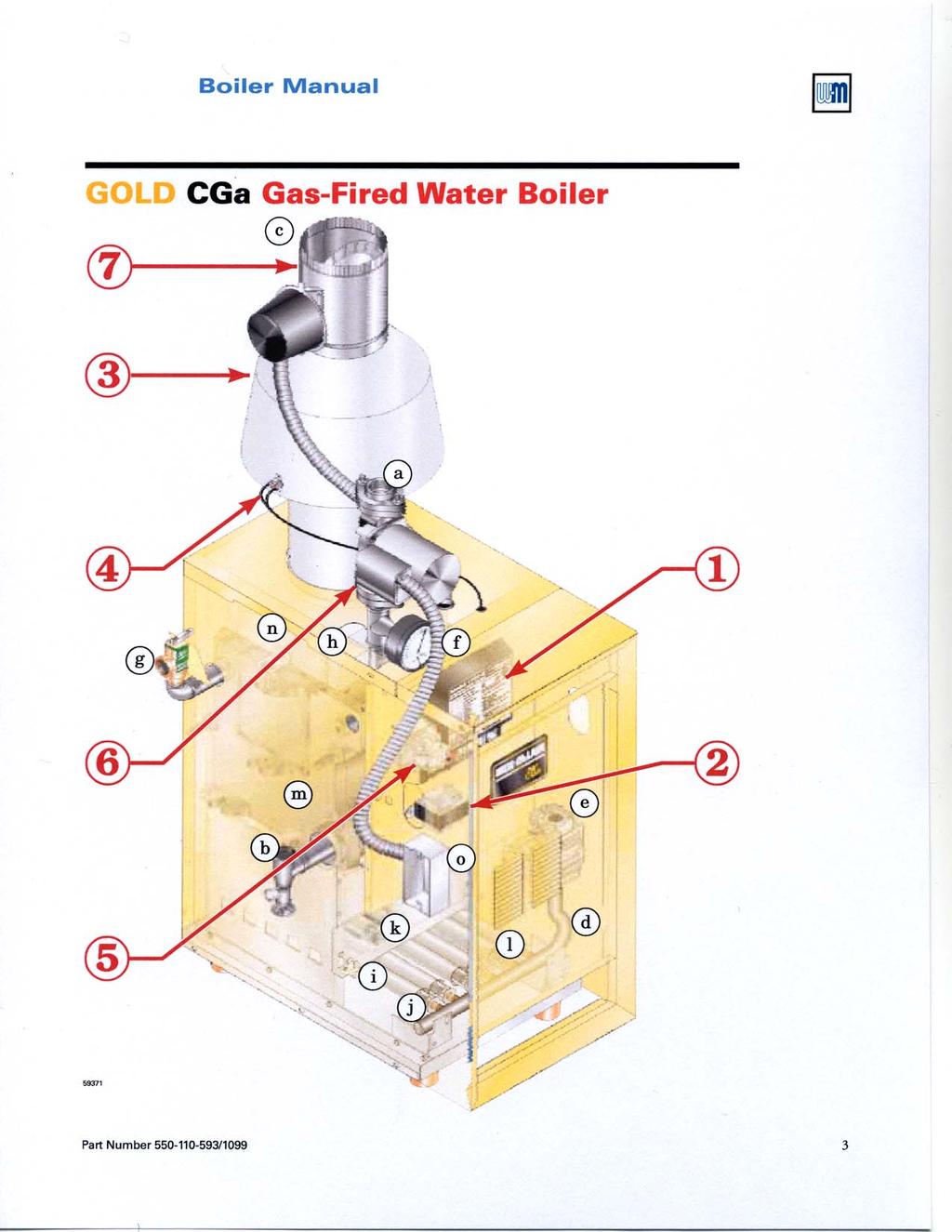
4 GOLD CGa Gas-Fired Water Boiler 1 How it works... Control module The control module (used on spark-ignited pilot boilers) responds to signals from the room thermostat and boiler limit circuit to operate the boiler circulator, pilot burner, gas valve and vent damper. When room thermostat calls for heat, the control module starts the system circulator and activates the vent damper (causing it to drive open). When the vent damper has opened completely, the control module opens the pilot valve and activates pilot ignition spark. The control module allows up to 15 seconds to establish pilot flame. If flame is not sensed within 15 seconds, the control module will turn off the gas valve, flash the Flame light, and immediately start a new cycle. This will continue indefinitely until pilot flame is established or power is interrupted. Once pilot flame is proven, the control module opens the gas valve to allow main burner flame. When the room thermostat is satisfied, the control module turns off the gas valve and deactivates the vent damper (causing it to close). The control module indicator lights show normal sequence when the lights are on steady. When a problem occurs, the control module flashes combinations of lights to indicate the most likely reason for the problem. See page 52 for details. Standing pilot boilers (controls not shown) use the pilot thermocouple to prove flame. If the thermocouple is satisfied, the gas valve and vent damper will open on a call for heat and close afterwards. 2 Transformer The control transformer reduces line voltage to 24 volts for the gas valve and limit circuit. 3 Draft hood The draft hood provides a minimum draft for the boiler, assuring adequate air for combustion if installed in accordance with manual and not modified in any way. 4 Spill switch The spill switch will shut down the boiler (requiring manual reset of the switch reset button) if the vent system becomes blocked. 5 Water temperature limit switch The water temperature limit switch turns off the gas valve if the temperature in the boiler goes above its setting. (The circulator will continue to run as long as there is a call for heat.) Boiler circulator The boiler circulator circulates water through the external (system) piping. The circulator is shipped loose, and can be mounted on either the boiler supply or return piping. The factory-installed circulator wiring harness provides ample length for either location. NOTE The control module provides a pump exercising routine. If the boiler is not operated for 30 days, the control module will power the circulator for 30 seconds, then turn off. 7 Vent damper The vent damper closes during off cycles to reduce heat loss from the house up the vent. Other boiler components: a b c d e supply to system f g h i j pressure/temperature gauge k pilot burner, typical l stainless steel burners m cast iron boiler sections n flue collector o junction box return from system relief valve flue outlet air vent connection burner manifold flame rollout switch gas valve burner orifice 2 Part Number /1099
5 GOLD CGa Gas-Fired Water Boiler Contents Standing pilot Spark-ignited pilot How it works 2 3 Hazard definitions 4 Please read before proceeding 5 1. Prepare boiler location Prepare boiler Water piping Gas piping Field wiring Start-up Check-out procedure Operation standing pilot boilers Operation spark-ignited pilot boilers Service and maintenance Troubleshooting 49 50, , Replacement parts Dimensions and ratings Hazard definitions The following defined terms are used throughout this manual to bring attention to the presence of hazards of various risk levels or to important information concerning the life of the product. Indicates presence of hazards that will cause severe personal injury, death or substantial property damage. Indicates presence of hazards that can cause severe personal injury, death or substantial property damage. Indicates presence of hazards that will or can cause minor personal injury or property damage. Indicates special instructions on installation, operation or maintenance that are important but not related to personal injury or property damage. 4 Part Number /1099
6 GOLD CGa Gas-Fired Water Boiler 1a Prepare boiler location codes & checklist Installations must follow these codes: Local, state, provincial, and national codes, laws, regulations and ordinances. National Fuel Gas Code, ANSI Z223.1 latest edition. Standard for Controls and Safety Devices for Automatically Fired Boilers, ANSI/ASME CSD-1, when required. National Electrical Code. For Canada only: B149.1 or B149.2 Installation Code, CSA C22.1 Canadian Electrical Code Part 1 and any local codes. Before locating the boiler, check the following: Check for nearby connection to: System water piping Venting connections Gas supply piping Electrical power Check area around boiler. Remove any combustible materials, gasoline and other flammable liquids. Failure to keep boiler area clear and free of combustible materials, gasoline and other flammable liquids and vapors can result in severe personal injury, death or substantial property damage. Boiler must be installed so that gas control system components are protected from dripping or spraying water or rain during operation or service. If new boiler will replace existing boiler, check for and correct system problems, such as: 1. System leaks causing oxygen corrosion or section cracks from hard water deposits. 2. Incorrectly-sized expansion tank. 3. Lack of antifreeze in boiler water causing system and boiler to freeze and leak. Figure 1 Minimum clearances (see page 7) Fresh air opening Top view Side elevation 6 Part Number /1099
7 Boiler Manual 1b Prepare boiler location clearances Service clearances 1. Provide the following clearances for cleaning and servicing the boiler and for access to controls and components: Clearance from: Minimum Top (for cleaning flueways) 35" Front (for access to controls and components) 18" Back 7" Left side (for cleaning and servicing) 24" Right side 7" 2. Provide at least screwdriver clearance to jacket front panel screws for removal of front panel for inspection and minor service. If unable to provide at least screwdriver clearance, install unions and shutoff valves in system so boiler can be moved for servicing. Flooring and foundation Flooring The CGa boiler is approved for installation on combustible flooring, but must never be installed on carpeting. Foundation Do not install boiler on carpeting even if foundation is used. Fire can result, causing severe personal injury, death or substantial property damage. 1. Provide a solid brick or minimum 2-inch thick concrete foundation pad if any of the following is true: floor can become flooded. the boiler mounting area is not level. 2. The minimum foundation size is: Small space installations 1. Provide the following clearances to combustible material for small space installations. (See Figure 1, page 6): Clearance from combustible Minimum materials (closet installations): Top (for cleaning flueways) 35" Front (provide means of access) 3" Back 7" Left side (provide means of access) 6" Right side 2" 2. Hot water pipes must be at least ¹ ₂" from combustible material. 3. Single-wall vent pipe must be at least 6 inches from combustible material. 4. Type B double-wall metal vent pipe refer to vent manufacturer s recommendation for clearances to combustible material. Boiler model Minimum foundation length Minimum foundation width CGa-25 25" 12" CGa-3 25" 12" CGa-4 25" 15" CGa-5 25" 18" CGa-6 25" 21" CGa-7 25" 24" CGa-8 25" 27" Residential garage installation Take the following special precautions when installing the boiler in a residential garage. If the boiler is located in a residential garage, per ANSI Z223.1, paragraph 5.1.9: Mount the boiler a minimum of 18 inches above the floor of the garage to assure the burner and ignition devices will be no less than 18 inches above the floor. Locate or protect the boiler so it cannot be damaged by a moving vehicle. Part Number /1099 7
8 GOLD CGa Gas-Fired Water Boiler 1c Prepare boiler location vent system Failure to follow all instructions can result in flue gas spillage and carbon monoxide emissions, causing severe personal injury or death. Inspect existing chimney before installing boiler. Failure to clean or replace perforated pipe or tile lining will cause severe personal injury or death. Do not alter boiler draft hood or place any obstruction or non-approved vent damper in breeching or vent system. CSA certification will become void. Flue gas spillage and carbon monoxide emissions will occur causing severe personal injury or death. When removing boiler from existing common vent system: At the time of removal of an existing boiler, the following steps shall be followed with each appliance remaining connected to the common venting system placed in operation, while the other appliances remaining connected to the common venting system are not in operation. a. Seal any unused openings in the common venting system. b. Visually inspect the venting system for proper size and horizontal pitch and determine there is no blockage or restriction, leakage, corrosion or other deficiencies which could cause an unsafe condition. c. Test vent system Insofar as is practical, close all building doors and windows and all doors between the space in which the appliances remaining connected to the common venting system are located and other spaces of the building. Turn on clothes dryers and any appliance not connected to the common venting system. Turn on any exhaust fans, such as range hoods and bathroom exhausts, so they will operate at maximum speed. Do not operate a summer exhaust fan. Close fireplace dampers. d. Place in operation the appliance being inspected. Follow the lighting/operating instructions. Adjust thermostat so appliance will operate continuously. e. Test for spillage at draft hood relief opening after 5 minutes of main burner operation. Use the flame of a match or candle. f. After it has been determined that each appliance remaining connected to the common venting system properly vents when tested as outlined above, return doors, windows, exhaust fans, fireplace dampers, and any other gas-burning appliance to their previous conditions of use. Any improper operation of common venting system should be corrected so the installation conforms with the National Fuel Gas Code, ANSI Z223.1-latest edition. Correct by resizing to approach the minimum size as determined using the appropriate tables in Part 11 of that code. Canadian installations must comply with B149.1 or B149.2 Installation Code. Chimney or vent requirements 1. Venting must be installed according to Part 7, Venting of Equipment, of National Fuel Gas Code, ANSI Z223.1-latest edition and applicable building codes. Canadian installations must comply with B149.1 or B149.2 Installation Codes. 2. See Ratings table on page 67 for minimum chimney or vent sizes. A chimney or vent without a listed cap should extend at least 3 feet above the highest point where it passes through a roof of a building and at least 2 feet higher than any portion of a building within a horizontal distance of 10 feet. A chimney or vent must not extend less than the distances stated above. 3. A lined chimney is preferred and must be used when required by local, state, provincial and national codes, laws, regulations and ordinances. Vitreous tile linings with joints that prevent retention of moisture and linings made of noncorrosive materials are best. Advice for flue connections and chimney linings can be obtained from local gas utility. Type B doublewall metal vent pipe or single-wall vent pipe may be used as a liner. 4. Cold masonry chimneys, also known as outside chimneys, typically have one or more walls exposed to outside air. When any atmospheric gas-fired boiler with automatic vent damper is vented through this type of chimney, the potential exists for condensation to occur. Condensation can damage a masonry chimney. Weil-McLain recommends the following to prevent possible damage. a. Line chimney with corrosion-resistant metal liner such as AL29-4C single-wall stainless steel or B-vent. Size liner per National Fuel Gas Code ANSI Z223.1-latest edition. b. Provide drain trap to remove any condensate. 5. Where two or more gas appliances vent into a common chimney or vent, equivalent area should be at least equal to area of vent outlet on largest appliance plus 50 percent of vent outlet area on additional appliance. 8 Part Number /1099
9 Boiler Manual 1d Prepare boiler location air contamination Please review the following information on potential combustion air contamination problems. Refer to Table 1 for products and areas which may cause contaminated combustion air. To prevent potential of severe personal injury or death, check for products or areas listed below before installing boiler. If any of these contaminants are found: remove contaminants permanently OR isolate boiler and provide outside combustion air. See national, provincial or local codes for further information. Table 1 Corrosive contaminants and likely locations Products to avoid Areas likely to have contaminants Spray cans containing chloro/fluorocarbons Permanent wave solutions Chlorinated waxes/cleaners Chlorine-based swimming pool chemicals Calcium chloride used for thawing Sodium chloride used for water softening Refrigerant leaks Paint or varnish removers Hydrochloric acid/muriatic acid Cements and glues Antistatic fabric softeners used in clothes dryers Chlorine-type bleaches, detergents, and cleaning solvents found in household laundry rooms Dry cleaning/laundry areas and establishments Swimming pools Metal fabrication plants Beauty shops Refrigeration repair shops Photo processing plants Auto body shops Plastic manufacturing plants Furniture refinishing areas and establishments New building construction Remodeling areas Garages with workshops Adhesives used to fasten building products and other similar products Part Number /1099 9
10 MODEL CGi MODEL CGi GOLD CGa Gas-Fired Water Boiler 1c Prepare boiler location air openings Combustion air and ventilation openings must comply with Section 5.3, Air for Combustion and Ventilation, of National Fuel Gas Code ANSI Z223.1-latest edition, or applicable local building codes. Canadian installations must comply with B149.1 or B149.2 Installation Codes. Provide adequate combustion and ventilation air to assure proper combustion and reduce the risk of severe personal injury, death or substantial property damage caused by flue gas spillage and carbon monoxide emissions. Air from inside building (boiler in interior room - Figure 2) 1. Tightly constructed buildings must be provided with openings to outside for combustion and ventilation air. These openings must be sized to handle all fuel burning appliances, exhaust or ventilation fans and fireplaces. Air directly from outside to boiler room 1. Tightly constructed buildings must be provided with combustion and ventilation air openings to boiler room, which are adequate to handle the boiler needs plus the needs of all other fuel burning appliances, exhaust or ventilation fans and fireplaces. 2. When combustion air is supplied to the boiler space directly through outside walls (Figure 3): Provide two permanent openings: One air opening within 12 inches of floor. A second opening within 12 inches of ceiling. Each opening must provide a minimum free area of 1 square inch per 4,000 Btuh of input of all appliances in room plus requirements for any exhaust fans in room. Figure 3 Air directly from outdoors 2. When openings to boiler room are taken to interior spaces, provide two permanent openings: One air opening within 12 inches of floor. A second opening within 12 inches of ceiling. Each opening must provide a minimum free area of 1 square inch per 1,000 Btuh of input of all appliances in room plus requirements for any exhaust fans in room. The interior space supplying combustion and ventilation air must have adequate infiltration from outside. Each opening free area = 1 sq. inch per 4,000 Btuh 59321b Other appliances CGa boiler 0 to 12" 0 to 12" Air opening Air opening Outside Figure 2 Air openings to interior space 3. When combustion air is supplied to the boiler space directly from outside or ventilated attic/crawl Each opening free area = 1 sq. inch per 1,000 Btuh 59321a Other appliances CGa boiler 0 to 12" 0 to 12" Air opening Add air openings to outside if building is tight construction. Air opening space through vertical ducts (Figure 4): Provide two permanent openings: One air opening within 12 inches of floor. A second opening within 12 inches of ceiling. Each opening must provide a minimum free area of 1 square inch per 4,000 Btuh of input of all appliances in room plus requirements for any exhaust fans in room. The duct cross sectional area must be no less than the required area of the permanent openings. 10 Part Number /1099
11 MODEL CGi MODEL CGi Boiler Manual Figure 4 Air from outdoors vertical ducts Special considerations Other appliances Outside or ventilated attic Each opening free area = 1 sq. inch per 4,000 Btuh 59321c Ventilated crawl space CGa boiler 4. When combustion air is supplied to the boiler space directly from outside through horizontal ducts (Figure 5): Provide two permanent openings: One air opening within 12 inches of floor. A second opening within 12 inches of ceiling. Each opening must provide a minimum free area of 1 square inch per 2,000 Btuh of input of all appliances in room plus requirements for any exhaust fans in room. The duct cross sectional area must be no less than the required area of the permanent openings. 12" or Tight construction ANSI Z223.1 defines unusually tight construction where: a. Walls and ceilings exposed to the outside atmosphere have a continuous water vapor retarder with a rating of 1 perm or less with openings gasketed, and... b. Weather-stripping has been added on openable windows and doors, and... c. Caulking or sealants are applied to areas such as joints around windows and door frames, between sole plates and floors, between wall-ceiling joints, between wall panels, at penetrations for plumbing, electrical, and gas lines, and in other openings. For buildings with such construction, provide air openings into the building from outside, sized per the appropriate case in Figure 3 if appliances are to use inside air for combustion and ventilation. Exhaust fans and air movers The appliance space must never be under a negative pressure, even if the appliance(s) are installed as direct vent. Always provide air openings sized not only to the dimensions required for the firing rate of all appliances, but also to handle the air movement rate of the exhaust fans or air movers using air from the building or space. Figure 5 Each opening free area = 1 sq. inch per 2,000 Btuh 59321d Other appliances Air from outdoors horizontal ducts CGa boiler 0 to 12" 0 to 12" Air opening Air opening Outside Motorized air dampers If the air openings are fitted with motorized dampers, electrically interlock the damper to: Prevent the boiler from firing if the damper is not fully open. Shut the boiler down should the damper close during boiler operation. To accomplish this interlock, wire an isolated contact (proving the damper open) in series with the thermostat input to the boiler. The boiler will not start if this contact is open, and will shut down should it open during operation. Part Number /
12 GOLD CGa Gas-Fired Water Boiler 2a Prepare boiler placement and setup Place boiler/crate near position 1. Leave boiler in crate and on pallet until installation site is ready. 2. Move entire crate and pallet next to selected location. 3. Remove crate. Leave boiler on pallet. 4. Remove boiler from pallet as follows: a. Tilt left side of boiler up and place a board under left legs. b. Tilt boiler the other way and place a board under right legs. c. Slide boiler backwards off pallet and into position. Do not drop boiler or bump jacket on floor or pallet. Damage to boiler can result. 5. Check level. a. Shim legs, if necessary. b. Do not alter legs. Inspect orifices and burners 1. Remove front jacket door. Remove base access panel (See Figure 32, item 4, page 62). 2. Check for correctly-sized manifold orifices. See Table 2 below for sizing. (The orifice size is stamped on the orifice spud barrel.) Correctly-sized manifold orifices must be used. Failure to do so will result in severe personal injury, death or substantial property damage. 3. Level and straighten burners. Burners must be properly seated in slots in burner rest with their openings face up. Main burner orifices must inject down center of burner. Failure to properly seat burners will result in severe personal injury, death or substantial property damage. 4. Reinstall access panel. Do not operate boiler without access panel secured in place. Failure to comply could cause momentary flame rollout on ignition of main flame, resulting in possible fire or personal injury hazard. Orifice replacement procedure (when required) 1. Remove access panel. 2. On gas manifold, mark location of main burner with attached pilot assembly. 3. Remove main burner with attached pilot assembly from manifold. Remove all remaining burners. 4. Remove and discard all main burner orifices in gas manifold. 5. Apply a small amount of pipe dope to each of the new orifices and install in the manifold. Make sure the orifices are aligned correctly, not cross-threaded in the manifold tappings. Use only pipe dope compatible with propane gas, even if boiler is to be operated on natural gas. Failure to comply could result in severe personal injury, death or substantial property damage. 6. Reinstall main burner with attached pilot assembly at location marked on gas manifold. Reinstall all remaining burners. 7. Follow check-out procedure, section 7, page 33. Table 2 Manifold orifice sizing Location Natural gas Propane gas U. S. Canada 0-2,000 ft over 2,000 ft 0-2,000 ft over 2,000 ft 2.00 mm (te 1) 1.30 mm (te 1) 0-2,000 ft 2,000-4, ,000 ft 2,000-4, mm 1.90 mm 1.30 mm 1.20 mm te 1: For elevations above 2,000 feet, contact your local Weil-McLain sales office for details. 12 Part Number /1099
13 Boiler Manual 2b Prepare boiler pressure test Perform hydrostatic pressure test Pressure test boiler before attaching water or gas piping or electrical supply (except as noted below). Prepare boiler for test 1. Remove the shipping nipple (from CGa supply tapping) and remove the boiler relief valve. Temporarily plug the relief valve tapping with a ¾" NPT pipe plug. 2. Remove 1¼" nipple, reducing tee and drain valve from accessory bag. Install in boiler return connection as shown on page 3 or in Figure 34, item 3, page 64. Install circulator on either the return or supply. 3. Remove 1¼" nipple, 1¼" tee, bushing and pressure/ temperature gauge from accessory bag. Pipe to boiler supply connection as shown in Figure 34, page 64. (Use pipe dope sparingly.) 4. Connect a hose to boiler drain valve, the other end connected to a fresh water supply. Make sure hose can also be used to drain boiler after test. 5. Connect a nipple and shutoff valve to system supply connection on the 1¼" tee. This valve will be used to bleed air during the fill. (Valve and nipple are not included with boiler.) 6. Connect a nipple and shutoff valve to system return connection (at circulator flange if circulator installed on return). This valve will be used to bleed air during the fill. (Valve and nipple are not included with boiler.) Fill and pressure test 1. Open the shutoff valves you installed on supply and return connections. 2. Slowly open boiler drain valve and fresh water supply to fill boiler with water. 3. When water flows from shutoff valves, close boiler drain valve. 4. Close shutoff valves. 5. Slowly reopen boiler drain valve until test pressure of not more than 45 psi is reached on the pressure/ temperature gauge. 6. Test at no more than 45 psi for no more than 10 minutes. 7. Make sure constant gauge pressure has been maintained throughout test. Check for leaks. Repair if found. Drain and remove fittings Do not leave boiler unattended. A cold water fill could expand and cause excessive pressure, resulting in severe personal injury, death or substantial property damage. Leaks must be repaired at once. Failure to do so can damage boiler, resulting in substantial property damage. Do not use petroleum-based cleaning or sealing compounds in boiler system. Severe damage to boiler will occur, resulting in substantial property damage. 1. Disconnect fill water hose from water source. 2. Drain boiler at drain valve or out hose, whichever provides best access to drain. Remove hose after draining if used to drain boiler. 3. Remove nipples and valves unless they will remain for use in the system piping. 4. Remove plug from relief valve tapping. See Section 3 to replace relief valve. Part Number /
14 GOLD CGa Gas-Fired Water Boiler 2c Prepare boiler draft hood & spill switch Draft hood installation 1. Secure draft hood to outlet at top of boiler with sheet metal screws. 2. Bottom of draft hood or skirt must have clearance dimension above jacket top panel as indicated on draft hood. Spill switch installation 1. Fasten spill switch to draft hood as shown in Figure 6 and Figure See Wiring diagram to connect wires: a. Standing pilot boiler see page 34. b. Spark-ignited pilot boiler see pages Do not alter boiler draft hood or place any obstruction or non-approved vent damper in breeching or vent system. CSA certification will become void. Flue gas spillage and carbon monoxide emissions will occur causing severe personal injury or death. Figure 6 Install spill switch Figure 7 Spill switch with wire harness Draft hood Spill switch Spill switch wire harness Damper harness knockout d Prepare boiler install vent piping 1. Connect from draft hood or vent damper outlet to chimney or vent with same size vent connector. 2. Where possible, vertical venting to the outside from the draft hood or vent damper outlet will offer best performance. 3. Where horizontal vent connector is used, slope upward at least ¼" per lineal foot toward chimney or vent and support with hangers to prevent sagging. 4. Breeching must not be connected to any portion of a mechanical draft system that can operate under positive pressure. Long horizontal vent connector, excessive number of elbow or tees, or other obstructions that restrict the flow of combustion gases should be avoided. Severe personal injury, death or substantial property damage could result. 14 Part Number /1099
15 Boiler Manual 2e Prepare boiler vent damper installation These systems are used on gas-fired boilers with vent dampers as shipped from factory. Boiler will not operate without vent damper installed. Only vent dampers listed in the Replacement parts list on page 61 are certified for use with CGa boilers. Any other vent damper installed could cause severe personal injury or death. Figure 8 Effikal damper Damper blade Standing pilot ignition systems Refer to vent manufacturer s instructions to install plug (shipped with damper) in damper hole. For standing pilot boilers only, install plug with 3 /8" diameter hole in vent damper hole. Spark-ignited pilot systems Refer to vent manufacturer s instructions to install plug (shipped with damper) in damper hole. For spark-ignited pilot boilers only, install plug with no hole in vent damper hole. Minimum clearances Provide a minimum of 6" between the vent damper and any combustible material. (Provide a minimum of 36 " between jacket top and combustible ceiling.) Installation Do not modify draft hood or vent damper, or make another connection between draft hood and vent damper or boiler except as noted below. This will void CSA certification and will not be covered by Weil- McLain warranty. Any changes will cause severe personal injury, death or substantial property damage. 1. Install vent damper horizontally or vertically as shown in vent damper manufacturer s instructions. Vent damper must be installed so that it serves only one boiler and so damper blade indicator is visible to the user. See Figure 8. Vent damper assemblies Johnson Controls damper Refer to vent manufacturer s instructions to install plug (shipped with damper) in damper hole. Damper blade indicator 2. Screws or rivets used to secure the vent damper to the draft hood must not interfere with rotation of the damper blade. 3. Install damper harness between damper actuator and knockout in jacket top panel. Use strain relief connectors and locknuts to secure both ends of damper harness. Keep wiring harness clear of all hot surfaces. WARNING LINE UP KEYWAY WHEN CONNECTING PLUGS. FORCING A MISMATCH CAN CAUSE A HAZARDOUS CONDITION. Keyway Key Read and apply the harness plug warning label (shown above) so that it is visible after installation. 5. Plug damper harness receptacle into damper harness plug. Bypassing (jumpering) vent damper will cause flue products such as carbon monoxide to escape into the house. This will cause severe personal injury or death. After boiler has operated once, if either end of harness is disconnected, the system safety shutdown will occur. The boiler will not operate until harness is reconnected. Hold-open switch (Effikal only) Install vent damper so that switch is visible and accessible to user Effikal damper Damper hold open switch must be in Automatic Operation position for system to operate properly. Part Number /
16 GOLD CGa Gas-Fired Water Boiler 3a Water piping general information General piping information If installation is to comply with ASME or Canadian requirements, an additional high temperature limit is needed. Install control in supply piping between boiler and isolation valve. Set second control to minimum 20 F above setpoint of first control. Maximum allowable setpoint is 240 F. See page 34 or 38, for wiring. A low water cutoff device is required when boiler is installed above radiation level or by certain state or local codes or insurance companies. Use low water cutoff designed for water installations. Electrode probe-type is recommended. Purchase and install in tee in supply piping above boiler. Use backflow check valve in cold water supply as required by local codes. Pressure/temperature gauge Install pressure/temperature gauge in tee on supply piping (as shown in drawing on page 3). The gauge well is a self-closing valve, allowing removal of the gauge without draining the system. Slowly remove pressure/temperature gauge from well. The self-closing valve could leak if clogged with sediment. If water begins to spray, stop removing gauge. Close system fill valve and drain enough water to release system pressure before continuing with gauge removal. Escaping hot water could cause severe personal injury. Circulator The circulator is shipped loose (wiring pre-attached to boiler) to allow you to locate it either in the return or supply piping, as desired. See page 3 for a typical installation. Pipe the expansion tank to the suction side of the circulator whenever possible. Install an air separator in the supply piping. Connect the expansion tank to the air separator only if the separator is on the suction side of the circulator. Always install the system fill connection at the same point as the expansion tank connection to the system. Figures 9 and 10 show typical near-boiler piping connections. System water piping See Figure 9 (diaphragm-type or bladder-type expansion tank) or Figure 10 (closed-type expansion tank) on page 21, and Table 3 below, for near-boiler and single-zone systems designed for return water at least 130 F. See pages to complete multiple-zone piping or pages to complete piping for radiant heating systems or converted gravity systems. Refer to page 25 for boilers used with refrigeration systems. Relief valve Install relief valve vertically in ¾" tapping on side of boiler. See Figure 9 or 10 and the tag attached to the relief valve for manufacturer s instructions. To avoid water damage or scalding due to relief valve operation: Discharge line must be connected to relief valve outlet and run to a safe place of disposal. Terminate the discharge line to eliminate possibility of severe burns should the valve discharge. Discharge line must be as short as possible and be the same size as the valve discharge connection throughout its entire length. Discharge line must pitch downward from the valve and terminate at least 6" above the floor drain where any discharge will be clearly visible. The discharge line shall terminate plain, not threaded, with a material serviceable for temperatures of 375 F or greater. Do not pipe the discharge to any place where freezing could occur. shutoff valve shall be installed between the relief valve and boiler, or in the discharge line. Do not plug or place any obstruction in the discharge line. Failure to comply with the above guidelines could result in failure of the relief valve to operate, resulting in possibility of severe personal injury, death or substantial property damage. Test the operation of the valve after filling and pressurizing system by lifting the lever. Make sure the valve discharges freely. If the valve fails to operate correctly, replace it with a new relief valve. Table 3 Water pipe size (based on 20 F rise) Boiler model To system From system CGa-25 ¾" ¾" CGa-3 1" 1" CGa-4 1" 1" CGa-5 1" 1" CGa-6 1¼" 1¼" CGa-7 1¼" 1¼" CGa-8 1½" 1½" te: Circulator flange supplied with boiler is same size as recommended piping above. Install boiler such that Chilled medium, if used, is piped in parallel with heating boiler. Use appropriate valves to prevent chilled medium from entering boiler. Consult I=B=R Installation and Piping Guides. If boiler is connected to heating coils located in air handling units where they can be exposed to refrigerated air, use flow control valves or other automatic means to prevent gravity circulation during cooling cycle. Circulation of cold water through the boiler could result in damage to the heat exchanger, causing possible severe personal injury, death or substantial property damage. 16 Part Number /1099
17 GOLD GOLD Boiler Manual 3b Water piping single-zone system Expansion tank Diaphragm-type or bladder-type expansion tank Figure 9 1. Ensure expansion tank size will handle boiler and system water volume and temperature. Tank must be located in boiler return piping as close to boiler as possible, before inlet side of circulator. See tank manufacturer s instructions for details. 2. Install an automatic air vent as shown. Closed-type expansion tank Figure Ensure expansion tank size will handle boiler and system water volume and temperature. See tank manufacturer s instructions for details. 2. Connect tank to ½" NPT tapping located behind supply outlet, using ½" NPT piping. Pitch any horizontal piping up towards tank 1 inch per 5 feet of piping. Undersized expansion tanks cause system water to be lost from relief valve and makeup water to be added through fill valve. Eventual section failure can result. Use Figure 9 or Figure 10 only for single-zone systems designed for return water at least 130 F. For systems with low return water temperature possible, such as converted gravity systems and radiant heating systems, refer to the special piping suggestions of pages Failure to prevent low return water temperature to the boiler could cause corrosion of the boiler sections or burners, resulting in severe personal injury, death or substantial property damage. Figure 9 Diaphragm- or bladder-type expansion tank Figure 10 Closed-type expansion tank Piping to single-zone system using diaphragm-type or bladder-type expansion tank. See Table 3 for piping sizes. From system Cold water fill To DIAPHRAGM expansion tank and fittings Piping to single-zone system using closedtype expansion tank. See Table 3 for piping sizes. CLOSED-type expansion tank Isolation valve Relief valve Isolation valve To system Circulator* Automatic air vent Isolation valve Relief valve From system Cold water fill Isolation valve To system Circulator* CGa CGa Circulator Drain valve Circulator Drain valve *Alternate location *Alternate location Part Number /
18 GOLD CGa Gas-Fired Water Boiler 3c Water piping multiple zones Piping multiple zones Follow instructions on pages 16 and 17 to install near-boiler or single-zone piping. (Also refer to Piping for radiant heating systems or converted gravity systems, below, if applicable.) See Figure 11 or Figure 12 to complete installation. Zoning with circulators, return temp over 130 F 1. Size each circulator to individual circuit requirements. 2. Do not install circulator on boiler (except for primary/secondary piping). 3. Install isolation (balancing) valves to adjust flow to distribute heat to all zones. 4. Install and wire a separate relay for each zone circulator. Zoning with zone valves, return temp over 130 F 1. Install isolation (balancing) valves to adjust flow to distribute heat to all zones. 2. Provide a separate 24-volt transformer to power the zone valves. Size the transformer to handle the total rated load of all connected zone valves. Piping for radiant heating systems or converted gravity systems Converted gravity (or steam) systems Whenever possible, use the primary/secondary piping shown in Figures 13 or 14 on page 21. This piping design allows changing boiler flow rate without affecting primary circuit flow rate. If Figures 13 or 14 cannot be used, use the boiler-bypass piping shown in Figure 15 or Figure 16 on page 23. You can also use the piping shown in Figure 17 on page 25 (system-bypass), if the reduced flow rate in the heating system will not cause heat distribution problems. Failure to prevent low return water temperature to the boiler could cause corrosion of the boiler sections or burners, resulting in severe personal injury, death or substantial property damage. Radiant heating systems Preferably, use primary/secondary piping, as shown in Figures 13 or 14 on page 21. Alternatively, use the method of either Figure 15 or Figure 16 on page 23. Do not use the piping of Figure 17 (system-bypass), because this method does not control radiant system supply temperature. If radiant system tubing has no oxygen barrier, a heat exchanger must be used. Radiant heating system piping should include a means of regulating the boiler return water temperature and the system supply temperature (such as provided by an injection pumping control). Boiler return water temperature will be adequately controlled using the methods shown in this manual provided the system supply temperature is relatively constant. Do not apply the methods in this manual if the system is equipped with an outdoor reset control. Instead, provide controls and piping which can regulate the boiler return water temperature at no less than 130 F regardless of system supply temperature. Contact your Weil-McLain representative for suggested piping and control methods. Failure to prevent cold return water temperature to the boiler could cause corrosion damage to the sections or burners, resulting in possible severe personal injury, death or substantial property damage. 18 Part Number /1099
19 GOLD GOLD Boiler Manual Typical piping multiple-zone installations Figure 11 Zoning with circulators return water 130 F or higher. ZONE 2 Figure 12 Zoning with zone valves return water 130 F or higher. ZONE 2 1 ZONE ZONE Alternate circulator location Cold water fill CGa Cold water fill CGa Boiler isolation (balancing) valves 2 Flow/check valve 3 System or zone circulator 5 Zone valve 6 Drain valve 9 Relief valve 10 Automatic air vent (with diaphragm-type expansion tank), or connect to tank fitting (closed-type expansion tank). DO NOT use an automatic air vent when using closed-type expansion tank. It would allow air to leave the system, causing waterlogging of the expansion tank. 11 Fill valve 12 Diaphragm-type or bladder-type expansion tank, if used (For closed-type expansion tank, pipe from top of air separator to tank fitting as in Figure 10.) 13 Air separator and automatic vent, if used (te that the fill valve must always be connected to the expansion tank, regardless of location of expansion tank circulator or air separator. For systems with possible low return-water temperature (such as converted gravity systems, radiant heating systems and heat pump systems), refer to the special piping suggestions of Figures 13 17, as applies. Failure to prevent sustained low return water temperature to the boiler could cause corrosion of the boiler sections, resulting in severe personal injury, death or substantial property damage. Part Number /
20 GOLD CGa Gas-Fired Water Boiler 3d Water piping low temp systems Primary/secondary (preferred) bypass piping method Primary/secondary bypass piping is preferred because the flow rate and temperature drop in the heating circuit(s) is determined only by the heating circuit circulator(s). So adjustment of the bypass valves in the boiler circuit will not cause a change in the heating circuit rate and temperature distribution. Figures 13 and 14 show suggested bypass arrangements using primary/secondary bypass piping (preferred) for low temperature systems such as radiant heating systems or converted gravity systems. For alternatives, see pages 22 through 25. The bypass valves (items 7a and 7b) provide mixing of hot boiler outlet water with cooler system return water set to assure a minimum return water temperature (at least 130 F) to the boiler. Set the valves as explained below. Temperature gauges Gauge 4a is suggested, but optional on any system. Gauge 4b is optional on converted gravity systems, but required on radiant heating systems to display the water temperature being supplied to the radiant tubing. Gauge 8 is required on all systems to assure the return water temperature is accurately set for a minimum of 130 F. If this gauge is not available however, adjust the valves such that the boiler-mounted temperature/pressure gauge reads at least 150 F when the system return water is cold (approximately 60 F water temperature). Valve adjustment (Figure 13 and 14 only) 1. Set the valves while the system is cool, setting for the coldest expected water temperature (usually 60 F since the system will often drop to room temperature between cycles). 2. Start with valve 7a fully closed and 7b fully open. 3. Gradually open valve 7a while closing valve 7b until the temperature at gauge 8 reads 130 F when gauge 4a reads 60 F. 4. te that valve 7a regulates the amount of hot water from the boiler supply which mixes with return water. Valve 7b regulates the amount of system water flowing through the boiler secondary loop. Failure to prevent low return water temperature to the boiler could cause corrosion of the boiler sections or burners, resulting in severe personal injury, death or substantial property damage. Radiant heating system piping should include a means of regulating the boiler return water temperature and the system supply temperature (such as provided by an injection pumping control). Boiler return water temperature will be adequately controlled using the methods shown in this manual provided the system supply temperature is relatively constant. DO NOT apply the methods of this manual if the system is equipped with an outdoor reset control. Instead, provide controls and piping which can regulate the boiler return water temperature at no less than 130 F regardless of system supply temperature. Contact your Weil-McLain representative for suggested piping and control methods. Failure to prevent cold return water temperature to the boiler could cause corrosion damage to the sections or burners, resulting in possible severe personal injury, death or substantial property damage. 20 Part Number /1099
21 GOLD GOLD Boiler Manual Primary/secondary (preferred) piping for radiant heating or converted gravity systems Figure 13 Zoning with circulators Figure 14 Zoning with zone valves ZONE 2 ZONE a ZONE 1 12" MAX. 4b b a ZONE 1 12" MAX. 4b b Cold water fill a 9 Alternate circulator location 10 CGa Cold water fill a 9 Alternate circulator location 10 CGa Boiler isolation (balancing) valves 2 Flow/check valve 3 System or zone circulator (circulator should cycle with zone valve and switches, using circulator valve or zone control panel) 4 System temperature gauges 5 Zone valve 6 Drain valve 7 System temperature valves (see instructions to the left for adjusting valves) 8 Blend temperature gauge 9 Relief valve 10 Automatic air vent (with diaphragm-type expansion tank), or connect to tank fitting (closed-type expansion tank). DO NOT use an automatic air vent when using closed-type expansion tank. It would allow air to leave the system, causing waterlogging of the expansion tank. 11 Fill valve 12 Diaphragm-type or bladder-type expansion tank, if used (For closed-type expansion tank, pipe from top of air separator to tank fitting as in Figure 10.) 13 Air separator and automatic vent, if used (te that the fill valve must always be connected to the expansion tank, regardless of location of expansion tank, circulator or air separator.) Part Number /
22 GOLD CGa Gas-Fired Water Boiler 3e Water piping low temp systems Boiler-bypass piping method This piping method is called a boiler-bypass because part of the circulator flow is bypassed around the boiler (through valve 7a). This method reduces the flow rate throughout the boiler, in order to raise the average water temperature in the boiler enough to prevent flue gas condensation. Boiler-bypass piping is effective for some boilers including the CGa provided the flow rates are adjusted according to the instructions following. Figures 15 and 16 are alternative piping suggestions for converted gravity (large water content or steam systems) or radiant heating system for use when primary/secondary piping can t be applied. (Figure 17 is another alternative, using system bypass in place of boiler-bypass piping. Figure 17 however, is not suitable for radiant heating applications because it does not protect the radiant system from possible high water temperature.) Boiler-bypass piping keeps system flow rate as high as possible and temperature drop as low as possible, helping to equalize the building heat distribution. Temperature gauges Gauge 4a is optional if the bypass valves will be adjusted using cold (or room temperature) return water to the boiler. (When setting the valves without gauge 4a installed using cold or room temperature water assume the return water temperature to be 60 F. Set the valves so gauge 8 reads at least 120 F. Gauge 4b is optional on converted gravity systems, but required on radiant heating systems to display the water temperature being supplied to the radiant tubing. Gauge 8 is required on all systems to assure reliable adjustment of the bypass valves. The boiler-mounted temperature/pressure gauge can be used if a separate temperature gauge is not installed. Valve adjustment 1. Start with valve 7a fully closed and 7b fully open. 2. Gradually open valve 7a while closing valve 7b until the temperature at gauge 8 reads 60 F higher than gauge 4a. A minimum 60 F temperature rise through the boiler assures a low enough flow rate and high enough average temperature to prevent condensation even with low system return water temperature. 3. Valve 7a regulates the system flow rate, while valve 7b regulates the boiler flow rate. 4. The boiler-mounted temperature/pressure gauge may be used in place of a separate gauge 8. Failure to prevent low return water temperature to the boiler could cause corrosion of the boiler sections or burners, resulting in severe personal injury, death or substantial property damage. Radiant heating system piping should include a means of regulating the boiler return water temperature and the system supply temperature (such as provided by an injection pumping control). Boiler return water temperature will be adequately controlled using the methods shown in this manual provided the system supply temperature is relatively constant. DO NOT apply the methods of this manual if the system is equipped with an outdoor reset control. Instead, provide controls and piping which can regulate the boiler return water temperature at no less than 130 F regardless of system supply temperature. Contact your Weil-McLain representative for suggested piping and control methods. Failure to prevent cold return water temperature to the boiler could cause corrosion damage to the sections or burners, resulting in possible severe personal injury, death or substantial property damage. 22 Part Number /1099
23 GOLD GOLD Boiler Manual Boiler-bypass (alternate) piping for radiant heating or converted gravity systems Figure 15 Boiler-bypass piping Figure 16 Boiler-bypass piping Zoning with circulators (Alternative to primary/secondary piping Figures 13 and 14) Zoning with zone valves (Alternative to primary/secondary piping Figures 13 and 14) ZONE 2 ZONE a ZONE 1 4b ZONE 1 4b a 7b 8 6 Alternate circulator location a 7b 8 Cold water fill CGa Cold water fill 11 4a CGa Boiler isolation (balancing) valves 2 Flow/check valve 3 System or zone circulator 4 System temperature gauges 5 Zone valve 6 Drain valve 7 System temperature valves (see instructions to the left for adjusting valves) 8 Blend temperature gauge 9 Relief valve 10 Automatic air vent (with diaphragm-type expansion tank), or connect to tank fitting (closed-type expansion tank). DO NOT use an automatic air vent when using closed-type expansion tank. It would allow air to leave the system, causing waterlogging of the expansion tank. 11 Fill valve 12 Diaphragm-type or bladder-type expansion tank, if used (For closed-type expansion tank, pipe from top of air separator to tank fitting as in Figure 10.) 13 Air separator and automatic vent, if used (te that the fill valve must always be connected to the expansion tank, regardless of location of expansion tank, circulator or air separator.) Part Number /
24 GOLD CGa Gas-Fired Water Boiler 3f Water piping low temp systems System-bypass piping method This piping method is called a system-bypass because part of the circulator flow bypasses the system (through valve 7a). This bypassed hot water from the boiler outlet mixes with cooler system return water temperature in order to provide minimum 130 F return water to the boiler. Valve 7b will most often be full open, but may need to be slightly closed on some low pressure drop systems in order to cause enough flow through valve 7a. Figure 17 is an alternative piping method that provides return water temperature control for boilers installed on converted gravity systems (large water content or steam systems). Do not apply the piping of Figure 17 on radiant heating systems. It provides no method of regulating the water temperature provided to the system and could result in excessive water temperature in the radiant tubing. System-bypass piping as shown in Figure 17 can be used with either zone valve or circulator zoning. When used with circulator zoning however, the boiler circulator (item 3), must be piped as shown. It cannot be used as one of the zoning circulators. Do not apply system-bypass piping if the reduced flow in the system could cause poor heat distribution. That is, system-bypass piping reduces the flow in the system and increases the water temperature supplied to the system. This can cause increased heat from radiators at the beginning of the system and reduced heat from radiators near the end of the system. Valve adjustment 1. Start with valve 7a fully closed and 7b fully open. 2. Gradually open valve 7a while closing valve 7b until the temperature at gauge 8 reads at least 130 F at all times. 3. Valve 7a regulates the amount of boiler supply water mixed with return water. Valve 7b causes a pressure drop in the system needed to balance flow through valve 7a and the system. 4. The valve adjustment should be done with the system at the coldest expected temperature (60 F for converted gravity systems or high mass radiant systems). Failure to prevent low return water temperature to the boiler could cause corrosion of the boiler sections or burners, resulting in severe personal injury, death or substantial property damage. Radiant heating system piping should include a means of regulating the boiler return water temperature and the system supply temperature (such as provided by an injection pumping control). Boiler return water temperature will be adequately controlled using the methods shown in this manual provided the system supply temperature is relatively constant. DO NOT apply the methods of this manual if the system is equipped with an outdoor reset control. Instead, provide controls and piping which can regulate the boiler return water temperature at no less than 130 F regardless of system supply temperature. Contact your Weil-McLain representative for suggested piping and control methods. Failure to prevent cold return water temperature to the boiler could cause corrosion damage to the sections or burners, resulting in possible severe personal injury, death or substantial property damage. 24 Part Number /1099
25 GOLD Boiler Manual 3f System-bypass (alternate) piping for converted gravity (or steam) systems From system 7a To system 7b Figure 17 System-bypass piping Zoning with zone valve or circulators, return water 130 F or higher. Cold water fill Alternate circulator location 10 GOLD CGa (Alternative to boiler-bypass piping Figures 15 and 16) 3 System or zone circulator 7 System temperature valves (see instructions to the left for adjusting valves) 8 Blend temperature gauge 9 Relief valve 10 Automatic air vent (with diaphragm-type expansion tank), or connect to tank fitting (closed-type expansion tank). DO NOT use an automatic air vent when using closed-type expansion tank. It would allow air to leave the system, causing waterlogging of the expansion tank. 11 Fill valve 12 Diaphragm-type or bladder-type expansion tank, if used (For closed-type expansion tank, pipe from top of air separator to tank fitting as in Figure 10.) 3g Water piping Refrigeration system Figure 18 Piping refrigeration systems Prevent chilled water from entering boiler System supply Circulator Water chiller Expansion tank Shut-off valve Install boiler so that chilled medium is piped in parallel with the heating boiler. Use appropriate valves to prevent chilled medium from entering boiler. See Figure 18 for typical installation of balancing valve and check valve. System return Strainer Check valve Balancing valve Boiler CGa If boiler is connected to heating coils located in air handling units where they can be exposed to refrigerated air, use flow control valves or other automatic means to prevent gravity circulation during cooling cycle. Part Number /
26 GOLD CGa Gas-Fired Water Boiler 4 Gas piping Connecting gas supply piping to boiler 1. Remove jacket front panel and refer to Figure 19 to pipe gas to boiler. a. Install drip leg at inlet of gas connection to boiler. Where local utility requires drip leg to be extended to the floor, use appropriate length of pipe between cap and tee. b. Install ground joint union for servicing, when required. c. Install manual shutoff valve in gas supply piping outside boiler jacket when required by local codes or utility requirements. d. In Canada When using manual main shutoff valve, it must be identified by the installer. 2. Support piping with hangers, not by boiler or its accessories. 3. Purge all air from gas supply piping. 4. Before placing boiler in operation, check boiler and its gas connection for leaks. a. Close manual main shutoff valve during any pressure testing at less than 13" w.c. b. Disconnect boiler and gas valve from gas supply piping during any pressure testing greater than 13" w.c. Do not check for gas leaks with an open flame Use bubble test. Failure to use bubble test or check for gas leaks can cause severe personal injury, death or substantial property damage. 5. Use pipe dope compatible with propane gases. Apply sparingly only to male threads of pipe joints so that pipe dope does not block gas flow. Failure to apply pipe dope as detailed above can result in severe personal injury, death or substantial property damage. Table 4 Gas pipe length (feet) Pipe capacity for 0.60 specific gravity natural gas Capacity of pipe for pipe size of: (Capacity in cubic feet gas per hour) ½" ¾" 1" 1¼" 1½" Natural Gas: 1. Refer to Table 4 for pipe length and diameter. Base on rated boiler input (divide by 1,000 to obtain cubic feet per hour). Table 4 is only for gas with specific gravity 0.60, with a pressure drop through the gas piping of 0.30" w.c. For additional gas pipe sizing information, refer to ANSI Z223.1 (or B149.1 or B149.2 for Canadian installations). 2. Inlet pressure required at gas valve inlet: Maximum: 13" w.c. Minimum: 5" w.c. Manifold gas pressure: 3.5" w.c. 3. Install 100% lockup gas pressure regulator in supply line if inlet pressure exceeds 13" w.c. Adjust for 13" w.c. maximum. Propane Gas: 1. Contact gas supplier to size pipes, tanks and 100% lockup gas pressure regulator. 2. Adjust propane supply regulator provided by gas supplier for 13" w.c. maximum pressure. 3. Inlet pressure required at gas valve inlet: Maximum: 13" w.c. Minimum: 11" w.c. Manifold gas pressure: 10" w.c. Figure 19 Gas supply piping Manual main shutoff gas valve (when required) Ground joint union (when required) Tee Nipple Cap Part Number /1099
27 Boiler Manual 5 Field wiring For your safety, turn off electrical power supply at service entrance panel before making any electrical connections to avoid possible electric shock hazard. Failure to do so can cause severe personal injury or death. Wiring must be N.E.C. Class 1. If rollout thermal fuse element wire as supplied with boiler must be replaced, type 200 C wire or equivalent must be used. If other original wiring as supplied with boiler must be replaced, use only type 105 C wire or equivalent. Boiler must be electrically grounded as required by National Electrical Code ANSI/NFPA 70-latest edition. Electrical installation must comply with: 1. National Electrical Code and any other national, state, provincial or local codes or regulations. 2. In Canada, CSA C22.1 Canadian Electrical Code Part 1, and any local codes. Wiring connections Boiler is shipped with controls completely wired, except spill switch and vent damper. Refer to wiring diagrams shown on page 34 for standing pilot ignition boiler or page 38 for spark-ignited pilot boiler. Thermostat 1. Connect thermostat as shown on wiring diagram on boiler. 2. Install on inside wall away from influences of drafts, hot or cold water pipes, lighting fixtures, television, sunrays or fireplaces. 3. If thermostat has a heat anticipator, set heat anticipator in thermostat to match power requirements of equipment connected to it. If connected directly to boiler, set for 0.1 amps plus gas valve current. See information on the wiring diagram shown in Figure 25b, page 39. For other devices, refer to manufacturer s specifications. Wiring diagram on boiler gives setting for control module and gas valve. Also see instructions with thermostat. Junction box (furnished) 1. Connect 120 VAC power wiring (Figure 20). 2. Fused disconnect or service switch (15 amp. recommended) may be mounted on this box. For those installations with local codes which prohibit installation of fused disconnect or service switch on boiler, install a 2 x 4 cover plate on the boiler junction box and mount the service switch remotely as required by the code. Wiring multiple zones Refer to zone valve manufacturer s literature for wiring and application. A separate transformer is required to power zone valves. Zoning with circulators requires a relay for each circulator. Figure 20 Field wiring connections service switch and thermostat (or end switch) provided by installer Field wiring Service switch (not provided) 120 VAC Hot Neutral Ground Thermostat or end switch (not provided) Service switch (not provided) Ground screw Wire nuts Thermostat or end switch (not provided) Factory wiring Black White Green Junction box, boiler left side Black Thermostat leads, through jacket left side Black Part Number /
28 GOLD CGa Gas-Fired Water Boiler 6a Start-up preparation Check for gas leaks Before starting the boiler, and during initial operation, smell near the floor and around the boiler for gas odorant or any unusual odor. Do not proceed with start-up if there is any indication of a gas leak. Repair any leak at once. Propane boilers only Your propane supplier mixes an odorant with the propane to make its presence detectable. In some instances, the odorant can fade and the gas may no longer have an odor. Propane gas can accumulate at floor level. Smell near the floor for the gas odorant or any unusual odor. If you suspect a leak, do not attempt to light the pilot. Use caution when attempting to light the propane pilot. This should be done by a qualified service technician, particularly if pilot outages are common. Periodically check the odorant level of your gas. Inspect boiler and system at least yearly to make sure all gas piping is leak-tight. Consult your propane supplier regarding installation of a gas leak detector. There are some products on the market intended for this purpose. Your supplier may be able to suggest an appropriate device. Determine if water treatment is needed Do not use petroleum-based cleaning or sealing compounds in boiler system. Severe damage to boiler will occur, resulting in substantial property damage. Eliminate all system leaks. Continual fresh makeup water will reduce boiler life. Minerals can build up in sections, reducing heat transfer, overheating cast iron, and causing section failure. Verify water chemistry Consult local water treatment companies for unusually hard water areas (above 7 grains hardness) or low ph water conditions (below 7.0). Boiler water ph of 7.0 to 8.5 is recommended. Freeze protection (when used) Use antifreeze made especially for hydronic systems. Inhibited propylene glycol is recommended. Do not use ethylene glycol, automotive or undiluted antifreeze. Severe personal injury or death can result. 1. Determine antifreeze quantity according to system water content. Boiler water content is listed on page 67. Remember to include expansion tank water content. 2. Follow antifreeze manufacturer's instructions. 3. A 50% solution of propylene glycol/water provides maximum protection to about -30 F. 4. Local codes may require back flow preventer or actual disconnect from city water supply. 5. When using antifreeze in a system with automatic fill, install a water meter to monitor water makeup. Glycol will leak before the water begins to leak, causing glycol level to drop. Added water will dilute the antifreeze, reducing the freeze protection level. 28 Part Number /1099
29 Boiler Manual Fill the system with water 1. Close manual and automatic air vents and boiler drain cock. 2. Fill to correct system pressure. Correct pressure will vary with each application. Typical cold water fill pressure for a residential system is 12 psi. 3. Purge air from system: a. Connect a hose to the purge valve (see drain valves, item 6, in suggested piping diagrams on pages 17 through 23, Figure 9 through Figure 16). Route hose to an area where water can drain and be seen. b. Close the boiler or system isolation valve between the purge valve and fill connection to the system. c. Close zone isolation valves. d. Open quick-fill valve on cold water makeup line. e. Open purge valve. f. One zone at a time, open the isolation valves. Allow water to run through the zone, pushing out the air. Run until no noticeable air flow is present. Close the zone isolation valves and proceed with the next zone. Follow this procedure until all zones are purged. g. Close the quick-fill water valve and purge valve and remove the hose. Open all isolation valves. Watch that system pressure rises to correct cold-fill pressure. h. After the system has operated for a while, eliminate any residual air by using the manual air vents located throughout the system. i. If purge valves are not installed in system, open manual air vents in system one at a time, beginning with lowest floor. Close vent when water squirts out. Repeat with remaining vents. 4. Open automatic air vent (diaphragm-type or bladder-type expansion tank systems only) one turn. 5. Open other vents: a. Starting on the lowest floor, open air vents one at a time until water squirts out. b. Repeat with remaining vents. 6. Refill to correct pressure. Inspect system water piping After filling the boiler and system with water, inspect all piping throughout the system for leaks. If found, repair immediately. Repeat this inspection after the boiler has been started and the system has heated up. Leaks must be repaired at once. Failure to do so can damage the boiler, resulting in substantial property damage. Do not use petroleum-based cleaning or sealing compounds in boiler system. Severe damage to boiler will occur, resulting in substantial property damage. Part Number /
30 GOLD CGa Gas-Fired Water Boiler 6a Start-up preparation continued Inspect base insulation The boiler contains ceramic fiber and fiberglass materials. Use care when handling these materials per instructions on page 68 of this manual. Failure to comply could result in severe personal injury. Failure to replace damaged insulation or reposition insulation can result in a fire hazard, causing severe personal injury, death or substantial property damage. Check to make sure insulation is secure against all four sides of the base. If insulation is damaged or displaced, do not operate boiler. Replace or reposition insulation. 6b Start-up operate boiler DO NOT proceed with boiler operation unless boiler and system have been filled with water and all instructions and procedures of previous manual sections have been completed. Failure to do so could result in severe personal injury, death or substantial property damage. Before starting the boiler... Read manual Section 8/9 and the Lighting/Operating instruction procedure (see Table 5, below). Verify the boiler and system are full of water. Verify the Start-up preparation procedures of Section 6 have been completed. Table 5 Lighting/Operating instruction location guide Models Standing pilot Gas Page Spark-ignited pilot Gas Page CGa-25 to CGa-6 CGa-7 to CGa-8 Natural or Honeywell VR8200/VR Honeywell VR8204/VR8304 Natural 40 Propane Robertshaw 7200 Natural 41 Robertshaw 7200 Natural 36 White-Rodgers 36E Natural 42 Natural or Honeywell VR8200/VR Honeywell VR8204/VR8304 Natural 40 Propane Robertshaw 7200 Natural 36 White-Rodgers 36C Natural Part Number /1099
31 Boiler Manual 6b Start-up operate boiler continued Start the boiler Follow the Lighting/Operating Instructions from Section 8 or 9 to start the boiler. Remove boiler jacket door and note the gas valve manufacturer and model number. Use only the lighting/operating instruction which applies to this gas valve (see Table 5, page 30). (The lighting instruction label on the boiler provides the same information.) See Section 6c, below, if boiler fails to start. Check system and boiler Eliminate all system leaks. Continual fresh makeup water will reduce boiler life. Minerals can build up in sections, reducing heat transfer, overheating cast iron, and causing section failure. If you discover evidence of any gas leak, shut down the boiler at once. Find the leak source with bubble test and repair immediately. Do not start boiler again until corrected. Failure to comply could result in severe personal injury, death or substantial property damage. Do not use petroleum-based cleaning or sealing compounds in boiler system. Severe damage to boiler will occur, resulting in substantial property damage. 1. Check system piping for leaks. If found, shut down boiler and repair immediately. 2. Vent air from system using manual vents. Air in the system will interfere with circulation and cause heat distribution problems and noise. 3. Inspect vent system thoroughly for signs of deterioration from corrosion, physical damage or sagging. Verify that masonry chimney liners are in good condition, with no obstructions, and there are no openings into the chimney. 4. Check around the boiler for gas odor following the procedure of section 6a, page 28 of this manual. 5. Verify operation per section 6d, page 32. Perform check-out procedure in section 7, page 33, and fill in the Installation and service certificate. 6c Start-up if boiler doesn t start... Check for: 1. Loose connections, blown fuse or service switch off? 2. High limit switch set below boiler water temperature? 3. Thermostat set below room temperature? 4. Gas not turned on at meter or boiler? 5. Incoming gas pressure less than: 5" w.c. for natural gas? 11" w.c. for propane gas? 6. If none of the above corrects the problem, refer to Troubleshooting, section 11, page 49 of this manual. Part Number /
32 GOLD CGa Gas-Fired Water Boiler 6d Start-up verify operation The boiler model suffix will be SPD. For spark-ignited pilot boilers (suffix PID ), see Section 8 or 9 for operation and lighting/operating information. Check burner flames Figure 21 Spark electrode Typical pilot burner flame Inner cone Pilot burner flame Proper pilot flame (see Figure 21): 1. Blue flame. 2. Inner cone engulfing thermocouple (standing pilot) or pilot flame sensor (spark-ignited pilot). 3. Thermocouple or pilot flame sensor glowing cherry red. Improper pilot flame: 1. Overfired Large flame lifting or blowing past pilot flame sensor. 2. Underfired Small flame. Inner cone not engulfing pilot flame sensor. 3. Lack of primary air Yellow flame tip. 4. Incorrectly heated pilot flame sensor. Main burner flame Proper main burner flame (see Figure 22): 1. Yellow-orange streaks may appear (caused by dust). Pilot flame sensor (sparkignited pilots) or Thermocouple (standing pilots) Figure 22 Typical main burner flame Transparent blue flame Improper main burner flame: 1. Overfired Large flames. 2. Underfired Small flames. 3. Lack of primary air Yellow tipping on flames (sooting will occur). Inner flame Check vent damper operation 1. Raise room thermostat to call for heat Vent damper actuator will slowly open vent damper. 2. When vent damper is fully open Main gas valve will open and main burners will ignite. (Sparkignited pilot controls will first light pilot, then allow main burners to ignite.) Vent damper must be fully open before main burners light. If vent damper does not fully open, flue products such as carbon monoxide will escape into house, causing severe personal injury or death. 3. Lower thermostat setting Main burner flames will go out, then vent damper will close. 4. Repeat Steps 2 through 4 several times to verify operation. 5. Return thermostat to normal setting. 6. Set thermostat heat anticipator setting indicated on wiring diagram. Check venting system operation 1. Check venting system at least once a month during heating season. With boiler firing, hold candle or match below lower edge of draft hood skirt. If flame does not blow out, but burns undisturbed, vent system is functioning properly. If flame blows out or flickers drastically, inspect vent system for obstructions or other causes of improper venting (such as exhaust fans in boiler room). 32 Part Number /1099
33 Boiler Manual 7 Check-out procedure checklist Boiler and heat distribution units filled with water? Automatic air vent, if used, open one full turn? Air purged from system? Air purged from gas piping? Piping checked for leaks? Correctly sized manifold orifices installed? Refer to Table 2, page 12 to check size and fuel type. Correctly sized manifold orifices must be used. Failure to do so will cause severe personal injury, death or substantial property damage. Followed lighting/operating instructions on boiler or in manual section 8, page 34 or section 9, page 37 for proper start-up? Proper burner flame observed? Refer to Check burner flame, manual section 6d, page 32. Test limit control While burners are operating, move indicator on limit control below actual boiler water temperature. Burners should go off while circulator continues to operate. Raise setting on limit control above boiler water temperature and burners should reignite. Test additional field-installed controls If boiler has a low water cutoff, additional high limit or other controls, test for operation as outlined by manufacturer. Burners should be operating and should go off when controls are tested. When controls are restored, burners should reignite. Botton on spill switch pushed in? Test ignition system safety device: a. Standing pilot Turn gas cock knob to PILOT position and extinguish pilot flame. Pilot gas flow should stop in less than 3 minutes. Put system back into operation (see section 6, pages 28-32). b. Spark-ignited pilot Connect manometer to outlet side of gas valve. Start boiler, allowing for normal startup cycle to occur and main burners to ignite. With main burners on, manually shut off gas supply at manual main shutoff gas valve. Burners should go off. Open manual main shutoff gas valve. Manometer should confirm there is no gas flow. Pilot will relight, flame sensing element will sense pilot flame and main burners reignite. Set limit control(s) to system temperature requirements. Adjust balancing valves and controls to provide design temperature to system. For multiple zones, adjust flow so it is about the same in each zone. Verify thermostat heat anticipator (if available) set properly? Refer to Field wiring, manual section 5, page 27, Thermostat(s). Cycle boiler with thermostat Raise to highest setting and verify boiler goes through normal start-up cycle. Lower to lowest setting and verify boiler goes off. Measure natural gas input: a. Operate boiler 10 minutes. b. Turn off other appliances. c. At natural gas meter, measure time (in seconds) required to use one cubic foot of gas. d. Calculate gas input: 3600 x 1000 number of seconds from step c = Btuh e. Btuh calculated should approximate input rating on boiler rating label. Check manifold gas pressure by connecting manometer to downstream test tapping on main gas valve. Manifold pressure for natural gas should be 3.5" w.c. and for propane gas should be 10" w.c. Observe several operating cycles for proper operation. Set room thermostat to desired room temperature. Fill in Installation and service certificate below? Review all instructions shipped with this boiler with owner or maintenance person. Return instructions to envelope and give to owner or place in pocket inside front panel in boiler. Installation and service certificate Boiler model Series CP number Date installed Measured Btuh input Installation instructions have been followed. Check out sequence has been performed. Above information is certified to be correct. Information received and left with owner/maintenance person Installer (company) (address) (phone) (installer s signature) Part Number /
34 GOLD CGa Gas-Fired Water Boiler 8a Operation standing pilot boilers Follow all procedures given in this manual and lighting instructions when operating the boiler. Failure to do so could result in severe personal injury, death or substantial property damage. 1. Standby mode: After pilot is manually lit, the gas valve provides pilot gas and maintains pilot as long as the thermocouple is satisfied. If thermocouple signal drops for any reason, pilot must be manually lighted, following the Lighting Instructions in this manual and on boiler. Vent damper will remain closed. 2. Call for heat: When thermostat circuit closes, the boiler circulator and vent damper are energized. The vent damper drives open. When the vent damper is fully open, its end switch energizes the main gas valve. This provides gas to the main burners. Burners remain ignited until thermostat circuit or limit circuit opens. Burners and circulator are deenergized when call for heat stops. Burners are deenergized, but circulator remains on, if the limit circuit opens. 3. Limit operation: When a limit control opens, the main gas valve is deenergized, but circulator continues to run. When the limit circuit closes again, the main gas valve is energized if there is still a call for heat. 4. Thermostat heat anticipator: Set heat anticipator as shown on wiring diagram, Figure 23. Figure 23 Wiring diagram Standing pilot system SCHEMATIC WIRING DIAGRAM LADDER WIRING DIAGRAM EQUIPMENT GROUND (NOTE 7) BK ADDITIONAL LIMITS (NOTE 6) BK BK BK SPILL SWITCH THERMOSTAT OR EMCS (NOTE 5) LIMIT CONTROL BK ROLLOUT TFE Y CABLE TO DAMPER DAMPER CONNECTOR H SERVICE SWITCH (BY OTHERS) CR2 120 V.A.C. PRIMARY CIRCULATOR N EQUIPMENT GROUND (NOTE 7) SERVICE SWITCH (BY OTHERS) H N W Y BK W G BK Y Y C G W R TRANSFORMER 120/24 V.A.C. PLUG-IN DPST RELAY Y G BK BL THERMO- COUPLE PILOT GAS VALVE BL R THERMOSTAT OR EMCS (NOTE 5) G 24 V.A.C RELAY COIL CR 5 2 CABLE TO DAMPER C CIRCULATOR WIRE NUT JUNCTION BOX CR1 FUSE DAMPER CONNECTOR NOTES: ELECTRICAL SHOCK HAZARD, CAN CAUSE SEVERE INJURY OR DEATH. DISCONNECT POWER BEFORE INSTALLING AND/OR SERVICING. 1. ALL WIRING MUST BE INSTALLED IN ACCORDANCE WITH: A. U.S.A. - NATIONAL ELECTRICAL CODE AND ANY OTHER NATIONAL, STATE OR LOCAL CODE REQUIREMENTS. B. CANADA - C.S.A. C22.1 CANADIAN ELECTRICAL CODE PART 1 AND ANY OTHER NATIONAL, PROVINCIAL OR LOCAL CODE REQUIREMENTS. 2. ALL CONTACTS SHOWN WITHOUT POWER APPLIED-OFF SHELF CONDITION. 3. IF ORIGINAL ROLLOUT TFE WIRE AS SUPPLIED WITH THE APPLIANCE MUST BE REPLACED, TYPE 200 o C WIRE OR ITS EQUIVALENT MUST BE USED. IF OTHER ORIGINAL WIRE AS SUPPLIED WITH THE APPLIANCE MUST BE REPLACED, TYPE 105 oc OR ITS EQUIVALENT MUST BE USED. 4. REFER TO CONTROL COMPONENT INSTRUCTIONS PACKED WITH BOILER FOR APPLICATION INFORMATION. 5. THERMOSTAT - FOR SINGLE ZONE SYSTEMS, THERMOSTAT ANTICIPATOR SETTING IS 0.40 AMPS. FOR MULTIPLE ZONE SYSTEMS USING ZONE VALVES OR CIRCULATORS, REFER TO COMPONENT MANUFACTURER S INSTRUCTIONS FOR APPLICATION WIRING AND THERMOSTAT ANTICIPATOR SETTING. EMCS - FOR EMCS CONNECTION IN PLACE OF THERMOSTAT, REFER TO EMCS INSTALLATION/OPERATING MANUAL. 6. L.W.C.O., ADDITIONAL HIGH LIMIT, ETC., WIRED IN SERIES. 7. DENOTES FIELD INSTALLED CHASSIS GROUND. CGa 25 thru 8 Y ADDITIONAL LIMITS (NOTE 6) SPILL SWITCH Standing Pilot Forced Hot Water LIMIT CONTROL LOW VOLTAGE FIELD HIGH VOLTAGE FIELD LOW VOLTAGE FACTORY HIGH VOLTAGE FACTORY THERMOCOUPLE Natural Or Propane Gas ROLLOUT TFE THERMOCOUPLE Weil-McLain 500 Blaine St. Michigan City, IN PART NUMBER GAS VALVE A United Dominion Company / Part Number /1099
35 Boiler Manual 8b Lighting instructions CGa-25 to CGa-8 FOR YOUR SAFETY READ BEFORE LIGHTING A. This appliance has a pilot, which must be lighted by hand. When lighting the pilot, follow these instructions exactly. B. Before LIGHTING, smell all around the appliance area for gas. Be sure to smell next to the floor because some gas is heavier than air and will settle on the floor. See below. Do not try to light any appliance. Do not touch any electric switch; do not use any phone in your building. 1. Stop! Read the safety information above on this label. 2. Set the thermostat to lowest setting. 3. When equipped with Effikal vent damper Model RVGP, place service switch in Hold Damper Open position. 4. Turn off all electrical power to the appliance. 5. When equipped with Johnson Controls vent damper Model M35, manually rotate damper blade in direction of arrow to Open position indicated on damper assembly. 6. Turn gas control knob clockwise to OFF. 7. When equipped with vent damper, verify damper blade is in full open position. Position indicator (shown in ON position) Red reset button Standing pilot Natural/Propane gas 8. Wait five (5) minutes to clear out any gas. Then smell for gas, including near the floor. If you smell gas, STOP! Follow "B" in the safety information above. If you don't smell gas, go to the next step. If you do not follow these instructions exactly, a fire or explosion may result causing property damage, personal injury or loss of life. C. Use only your hand to push down the reset button or turn the gas control knob. Never use tools. If the knob or reset button will not operate by hand, don't try to repair it, call a qualified service technician. Force or attempted repair may result in a fire or explosion. D. Do not use this appliance if any part has been under water. Immediately call a qualified service technician to inspect the appliance and to replace any part of the control system and any gas control, which has been under water. WHAT TO DO IF YOU SMELL GAS LIGHTING INSTRUCTIONS Gas control knob Immediately call your gas supplier from a neighbor s phone. Follow the gas supplier s instructions. If you cannot reach your gas supplier, call the fire department. TO TURN OFF GAS TO THE APPLIANCE 1. Set the thermostat to lowest setting. 2. Turn off all electric power to the appliance if service is to be performed. Gas valve manufacturer Honeywell Gas valve model(s) VR8200/VR Remove access panel located above burners. 10. Find pilot follow metal tube from gas control. The pilot is between two burners behind the access panel. 11. Turn gas control knob counterclockwise to PILOT. 12. Push in red reset button and hold. Immediately light the pilot with a match. Continue to hold reset button in for about one (1) minute after the pilot is lit. 13. Release reset button. Pilot should remain lit. If pilot goes out, repeat steps 6 through 13. If reset button stays depressed after release, stop and immediately call your service technician or gas supplier. If the pilot will not stay lit after several tries, turn the gas control knob clockwise to OFF and call your service technician or gas supplier. 14. Replace access panel. 15. Turn gas control knob counterclockwise to ON. 16. Turn on all electric power to the appliance. 17. When equipped with Effikal vent damper, place service switch in Automatic Operation position. 18. Set thermostat to desired setting. 19. Replace front panel. 3. Remove front panel. 4. Turn gas control knob clockwise to OFF. 5. Replace front panel. Part Number /
36 GOLD CGa Gas-Fired Water Boiler 8b Lighting instructions CGa-25 to CGa-8 FOR YOUR SAFETY READ BEFORE LIGHTING A. This appliance has a pilot, which must be lighted by hand. When lighting the pilot, follow these instructions exactly. B. Before LIGHTING, smell all around the appliance area for gas. Be sure to smell next to the floor because some gas is heavier than air and will settle on the floor. See below. Do not try to light any appliance. Do not touch any electric switch; do not use any phone in your building. 1. Stop! Read the safety information above on this label. 2. Set the thermostat to lowest setting. 3. When equipped with Effikal vent damper Model RVGP, place service switch in Hold Damper Open position. 4. Turn off all electrical power to the appliance. 5. When equipped with Johnson Controls vent damper Model M35, manually rotate damper blade in direction of arrow to Open position indicated on damper assembly. 6. Depress and move selector arm left to OFF. 7. When equipped with vent damper, verify damper blade is in full open position. Position indicator (shown in OFF position) Standing pilot Natural gas 8. Wait five (5) minutes to clear out any gas. Then smell for gas, including near the floor. If you smell gas, STOP! Follow "B" in the safety information above. If you don't smell gas, go to the next step. If you do not follow these instructions exactly, a fire or explosion may result causing property damage, personal injury or loss of life. C. Use only your hand to depress the selector arm. Never use tools. If the selector arm will not move by hand, don't try to repair it, call a qualified service technician. Force or attempted repair may result in a fire or explosion. D. Do not use this appliance if any part has been under water. Immediately call a qualified service technician to inspect the appliance and to replace any part of the control system and any gas control, which has been under water. WHAT TO DO IF YOU SMELL GAS LIGHTING INSTRUCTIONS Selector arm Immediately call your gas supplier from a neighbor s phone. Follow the gas supplier s instructions. If you cannot reach your gas supplier, call the fire department. TO TURN OFF GAS TO THE APPLIANCE 1. Set the thermostat to lowest setting. 2. Turn off all electric power to the appliance if service is to be performed. Gas valve manufacturer Robertshaw Gas valve model(s) Remove access panel located above burners. 10. Find pilot follow metal tube from gas control. The pilot is between two burners behind the access panel. 11. Move selector arm on gas control right to SET position. 12. Hold selector arm in SET position and immediately light the pilot with a match. Continue to hold selector arm to SET for about one-half (¹ ₂) minute after the pilot is lit. 13. Release selector arm. If pilot does not remain lit, repeat steps 6 through 13. If the pilot will not stay lit after several tries, move selector arm left to OFF and call your service technician or gas supplier. 14. Replace access panel. 15. Turn selector arm left to ON. 16. Turn on all electric power to the appliance. 17. When equipped with Effikal vent damper, place service switch in Automatic Operation position. 18. Set thermostat to desired setting. 19. Replace front panel. 3. Remove front panel. 4. Depress and move selector arm left to OFF. 5. Replace front panel. 36 Part Number /1099
37 Boiler Manual 9a Operation spark-ignited pilot boilers Follow all procedures given in this manual and operating instructions when operating the boiler. Failure to do so could result in severe personal injury, death or substantial property damage. 1. Standby: With no call for heat, the vent damper and circulator are deenergized. gas flows to pilot or main gas valve. 2. Call for heat (thermostat circuit closes): a. Vent damper and circulator energized if pilot status acceptable. Vent damper drives open. When vent damper end switch makes circuit, ignition control begins pilot ignition attempt. b. Ignition control checks for false flame signal: If ignition control senses pilot signal when no pilot gas should be present, control will lockout, requiring reset procedure as given in Figure Pilot ignition: Control module sparks the pilot and opens pilot valve in main gas valve. a. If pilot does light and control module senses flame current, spark generator is turned off and main valve opens. b. If pilot does not light within 15 seconds, pilot valve is closed and spark generator is turned off. Control module waits 5 minutes, then attempts to ignite pilot again. This cycle will continue indefinitely if pilot ignition control does not sense pilot flame. 4. Main burner operation: a. Control module monitors pilot flame current. If signal is lost, main valve closes, spark generator activates and sequence returns to step 4. b. If power is interrupted, control system shuts off pilot and main gas valves and restarts at step 1 when power is restored. c. In the event the limit control shuts down the boiler The control module closes the main gas valve, but keeps the circulator operating and the vent damper open. 5. Thermostat satisfied (thermostat circuit opens) Pilot and main gas valves are closed Vent damper is deenergized, and cycles to closed position. Circulator is shut off. 6. Boiler is now in the standby mode. 7. Thermostat anticipator setting: Set thermostat heat anticipator as instructed in Figure 25b, page 39. Figure 24 Steps Ignition control module sequence of operation status light indications (Following step 7, cycle goes back to step 1.) Call for heat? POWER TSTAT CIRC LIMIT DAMPER FLAME Timing 1. Standby Waiting for call for heat 2. Call for heat Circulator on 3. Limit circuit Limit controls closed 4. Damper circuit Damper proven open 5. Pilot flame proven * Gas valve open Pilot remains on Boiler producing heat 6. Limit cycle Limit circuit open Gas valve closed 7. Flame outage * Flame out Boiler recycles 8. Thermostat satisfied Circulator off NO YES YES YES YES YES YES NO 15 sec 15 sec 9. Circulator exercise routine Circulator turns on for 30 seconds NO 30 sec if boiler not operated for 30 days or = "ON" = "OFF" * If pilot flame is not proven in 15 seconds, control module will flash the FLAME light, but will continue indefinitely with attempts to light the pilot burner. The control module will not lockout on a failure to establish flame. It will lockout if line voltage polarity is reversed, stray voltage is sensed on thermostat line, or if flame is sensed when it shouldn t be there. The boiler will reset after these lockouts if any of the following occurs: 1 hour waiting period Opening and closing of thermostat circuit Removal of 120 VAC power for at least 45 seconds Part Number /
38 OFF ON GOLD CGa Gas-Fired Water Boiler 9a Operation spark-ignited pilot system continued Figure 25a Schematic wiring diagram Spark-ignited pilot system White Red B The control module is polarity-sensitive to the incoming 120 VAC power. If polarity is reversed, control will flash the POWER light when powered and will not cycle boiler. All contacts shown without power applied. Connector and status light locations/orientations may vary. W Plug-in connectors TRANSFORMER Items not provided 120 VAC Hot Neutral SERVICE SWITCH Wire nuts Junction box, boiler left side CIRCULATOR Ground screw Black White Green Gnd FIELD WIRING Black Jacket opening, boiler left side THERMOSTAT Black BR R W Y CONTROL MODULE Y B B BL R W W W Y B W G G W G Y R B R B BR B W PILOT BURNER O WATER TEMPERATURE LIMIT SWITCH 59347b SPILL SWITCH Y B Y B Y ROLLOUT TFE Additional limits, if used (note 7) G R B Y VENT DAMPER (Honeywell VR8204 shown) BL "C" W "A" R "B" GAS VALVE Terminal block (See Table G) 38 Part Number /1099
39 Boiler Manual Figure 25b Ladder wiring diagram Spark-ignited pilot system Electrical shock hazard can cause severe injury or death. Disconnect power before installing or servicing. Hot SERVICE SWITCH 120 VAC Neutral Gnd Legend for ladder wiring diagram 120 VAC field wiring Low voltage field wiring 120 VAC factory wiring Low voltage factory wiring High voltage spark ignition wiring Ground connectors HIGH VOLTAGE PILOT IGNITION ELECTRODE CONTROL MODULE 120 VAC SECTION CIRCULATOR Table G: Gas valve terminals and anticipator settings 120 VAC Gas valve "A" "B" "C" Honeywell VR8204 Honeywell VR8304 Robertshaw 7200 White-Rodgers 36C MV/PV MV/PV C MV MV M PV PV P 2 4 * 1 3 * Terminals 2 4 are factory-jumpered on the White-Rodgers 36C gas valve. Anticipator amps G 24 VAC POWER 24VAC CONSTANT 1. All wiring must be installed in accordance with: A. U.S.A. N.E.C. And any other national, state, or local code requirements. B. Canada C.S.A. C22.1 C.E.C. Part 1 and any other national, provincial, or local code requirements. 2. Pilot lead wires are not field replaceable. Replace pilot assembly if necessary. 3. If any of the original wire as supplied with the appliance must be replaced, use minimum 105 C wire or equivalent. Exception wires to a rollout TFE must be 200 C or equivalent. 4. Thermostat anticipator setting (single zone) see Table G for anticipator setting, depending on which gas valve is installed in boiler. 5. For multiple zoning, use either zone valves or circulators. Refer to the component manufacturer's instructions and this manual for application and wiring suggestions. 6. Refer to control component instructions packed with the boiler for application information. 7. Wire any additional limit controls (low water cutoff, additional high limit, etc.) in series with boiler limit control as shown. ROLLOUT TFE 59347a THERMOSTAT Additional limits (note 7) WATER TEMPERATURE LIMIT SWITCH SPILL SWITCH DAMPER END SWITCH (INTERNAL TO DAMPER) PILOT FLAME SENSOR HIGH VOLTAGE R R TSTAT/CIRC LIMIT CONTROL MODULE LOW VOLTAGE SECTION R R DAMPER FLAME VENT DAMPER 24VAC CALL FOR HEAT PILOT GAS VALVE "C" "B" "A" MAIN GAS VALVE See Table G Part Number /
40 GOLD CGa Gas-Fired Water Boiler 9b Operating instructions CGa-25 to CGa-8 Spark pilot Natural gas FOR YOUR SAFETY READ BEFORE OPERATING A. This appliance is equipped with an ignition device which automatically lights the pilot. Do not try to light the pilot by hand. B. Before OPERATING, smell all around the appliance area for gas. Be sure to smell next to the floor because some gas is heavier than air and will settle on the floor. See below. Do not try to light any appliance. Do not touch any electric switch; do not use any phone in your building. Gas valve manufacturer Honeywell Gas valve model(s) VR8204/VR8304 If you do not follow these instructions exactly, a fire or explosion may result causing property damage, personal injury or loss of life. C. Use only your hand to turn the gas control knob. Never use tools. If the knob will not turn by hand, don't try to repair it, call a qualified service technician. Force or attempted repair may result in a fire or explosion. D. Do not use this appliance if any part has been under water. Immediately call a qualified service technician to inspect the appliance and to replace any part of the control system and any gas control, which has been under water. WHAT TO DO IF YOU SMELL GAS OPERATING INSTRUCTIONS Immediately call your gas supplier from a neighbor s phone. Follow the gas supplier s instructions. If you cannot reach your gas supplier, call the fire department. 1. Stop! Read the safety information above on this label. 2. Set the thermostat to lowest setting. 3. When equipped with Effikal vent damper Model RVGP, place service switch in Hold Damper Open position. 4. Turn off all electrical power to the appliance. 5. When equipped with Johnson Controls vent damper Model M35, manually rotate damper blade in direction of arrow to Open position indicated on damper assembly. 6. This appliance is equipped with an ignition device which automatically lights the pilot. Do not try to light the pilot by hand. 7. Turn gas control knob clockwise to OFF. Position indicator (shown in ON position) Gas control knob 8. When equipped with vent damper, verify damper blade is in full open position. 9. Wait five (5) minutes to clear out any gas. Then smell for gas, including near the floor. If you smell gas, STOP! Follow "B" in the safety information above. If you don't smell gas, go to the next step. 10. Turn gas control knob counterclockwise to ON. 11. Turn on all electric power to the appliance. 12. When equipped with Effikal vent damper, place service switch in Automatic Operation position. 13. Set thermostat to desired setting. 14. If the appliance will not operate, follow the instructions To Turn Off Gas To The Appliance and call your service technician or gas supplier. 15. Replace front panel. TO TURN OFF GAS TO THE APPLIANCE 1. Set the thermostat to lowest setting. 2. Turn off all electric power to the appliance if service is to be performed. 3. Remove front panel. 4. Turn gas control knob clockwise to OFF. Do not force. 5. Replace front panel. 40 Part Number /1099
41 Boiler Manual 9b Operating instructions CGa-25 to CGa-6 FOR YOUR SAFETY READ BEFORE OPERATING A. This appliance is equipped with an ignition device which automatically lights the pilot. Do not try to light the pilot by hand. B. Before OPERATING, smell all around the appliance area for gas. Be sure to smell next to the floor because some gas is heavier than air and will settle on the floor. See below. Do not try to light any appliance. Do not touch any electric switch; do not use any phone in your building. 1. Stop! Read the safety information above on this label. 2. Set the thermostat to lowest setting. 3. When equipped with Effikal vent damper Model RVGP, place service switch in Hold Damper Open position. 4. Turn off all electrical power to the appliance. 5. When equipped with Johnson Controls vent damper Model M35, manually rotate damper blade in direction of arrow to Open position indicated on damper assembly. 6. This appliance is equipped with an ignition device which automatically lights the pilot. Do not try to light the pilot by hand. 7. Depress and move selector arm to OFF. te: Selector arm cannot be moved to OFF unless selector arm is depressed slightly. Do not force. Position indicator (shown in OFF position) Spark pilot Natural gas If you do not follow these instructions exactly, a fire or explosion may result causing property damage, personal injury or loss of life. C. Use only your hand to depress or move the selector arm. Never use tools. If the selector arm will not depress or move by hand, don't try to repair it, call a qualified service technician. Force or attempted repair may result in a fire or explosion. D. Do not use this appliance if any part has been under water. Immediately call a qualified service technician to inspect the appliance and to replace any part of the control system and any gas control, which has been under water. WHAT TO DO IF YOU SMELL GAS OPERATING INSTRUCTIONS Selector arm Immediately call your gas supplier from a neighbor s phone. Follow the gas supplier s instructions. If you cannot reach your gas supplier, call the fire department. TO TURN OFF GAS TO THE APPLIANCE 1. Set the thermostat to lowest setting. 2. Turn off all electric power to the appliance if service is to be performed. 3. Remove front panel. Gas valve manufacturer Robertshaw Gas valve model(s) When equipped with vent damper, verify damper blade is in full open position. 9. Wait five (5) minutes to clear out any gas. Then smell for gas, including near the floor. If you smell gas, STOP! Follow "B" in the safety information above. If you don't smell gas, go to the next step. 10. Move selector arm to ON. 11. Turn on all electric power to the appliance. 12. When equipped with Effikal vent damper, place service switch in Automatic Operation position. 13. Set thermostat to desired setting. 14. If the appliance will not operate, follow the instructions To Turn Off Gas To The Appliance and call your service technician or gas supplier. 15. Replace front panel. 4. Depress and move selector arm to OFF. Do not force. 5. Replace front panel. Part Number /
42 GOLD CGa Gas-Fired Water Boiler 9b Operating instructions CGa-25 to CGa-6 Spark pilot Natural gas FOR YOUR SAFETY READ BEFORE OPERATING A. This appliance is equipped with an ignition device which automatically lights the pilot. Do not try to light the pilot by hand. B. Before OPERATING, smell all around the appliance area for gas. Be sure to smell next to the floor because some gas is heavier than air and will settle on the floor. See below. Do not try to light any appliance. Do not touch any electric switch; do not use any phone in your building. 1. Stop! Read the safety information above on this label. 2. Set the thermostat to lowest setting. 3. When equipped with Effikal vent damper Model RVGP, place service switch in Hold Damper Open position. 4. Turn off all electrical power to the appliance. 5. When equipped with Johnson Controls vent damper Model M35, manually rotate damper blade in direction of arrow to Open position indicated on damper assembly. 6. This appliance is equipped with an ignition device which automatically lights the pilot. Do not try to light the pilot by hand. 7. Turn gas control knob clockwise to OFF. Gas valve manufacturer White-Rodgers Gas valve model(s) 36E If you do not follow these instructions exactly, a fire or explosion may result causing property damage, personal injury or loss of life. C. Use only your hand to turn the gas control knob. Never use tools. If the knob will not turn by hand, don't try to repair it, call a qualified service technician. Force or attempted repair may result in a fire or explosion. D. Do not use this appliance if any part has been under water. Immediately call a qualified service technician to inspect the appliance and to replace any part of the control system and any gas control, which has been under water. WHAT TO DO IF YOU SMELL GAS OPERATING INSTRUCTIONS Immediately call your gas supplier from a neighbor s phone. Follow the gas supplier s instructions. If you cannot reach your gas supplier, call the fire department. 8. When equipped with vent damper, verify damper blade is in full open position. 9. Wait five (5) minutes to clear out any gas. Then smell for gas, including near the floor. If you smell gas, STOP! Follow "B" in the safety information above. If you don't smell gas, go to the next step. 10. Turn gas control knob counterclockwise to ON. 11. Turn on all electric power to the appliance. 12. When equipped with Effikal vent damper, place service switch in Automatic Operation position. Position indicator (shown in ON position) Gas control knob 13. Set thermostat to desired setting. 14. If the appliance will not operate, follow the instructions To Turn Off Gas To The Appliance and call your service technician or gas supplier. 15. Replace front panel. TO TURN OFF GAS TO THE APPLIANCE 1. Set the thermostat to lowest setting. 2. Turn off all electric power to the appliance if service is to be performed. 3. Remove front panel. 4. Turn gas control knob clockwise to OFF. Do not force. 5. Replace front panel. 42 Part Number /1099
43 Boiler Manual 9b Operating instructions CGa-7 to CGa-8 FOR YOUR SAFETY READ BEFORE OPERATING A. This appliance is equipped with an ignition device which automatically lights the pilot. Do not try to light the pilot by hand. B. Before OPERATING, smell all around the appliance area for gas. Be sure to smell next to the floor because some gas is heavier than air and will settle on the floor. See below. Do not try to light any appliance. Do not touch any electric switch; do not use any phone in your building. 1. Stop! Read the safety information above on this label. 2. Set the thermostat to lowest setting. 3. When equipped with Effikal vent damper Model RVGP, place service switch in Hold Damper Open position. 4. Turn off all electrical power to the appliance. 5. When equipped with Johnson Controls vent damper Model M35, manually rotate damper blade in direction of arrow to Open position indicated on damper assembly. 6. This appliance is equipped with an ignition device which automatically lights the pilot. Do not try to light the pilot by hand. 7. Depress gas control knob slightly and turn clockwise to OFF. te: Knob cannot be turned to OFF unless knob is depressed slightly. Do not force. Position indicator (shown in ON position) Spark pilot Natural gas If you do not follow these instructions exactly, a fire or explosion may result causing property damage, personal injury or loss of life. C. Use only your hand to depress or turn the gas control knob. Never use tools. If the knob will not depress or turn by hand, don't try to repair it, call a qualified service technician. Force or attempted repair may result in a fire or explosion. D. Do not use this appliance if any part has been under water. Immediately call a qualified service technician to inspect the appliance and to replace any part of the control system and any gas control, which has been under water. WHAT TO DO IF YOU SMELL GAS OPERATING INSTRUCTIONS Gas control knob Gas valve manufacturer White-Rodgers Gas valve model(s) 36C Immediately call your gas supplier from a neighbor s phone. Follow the gas supplier s instructions. If you cannot reach your gas supplier, call the fire department. 8. When equipped with vent damper, verify damper blade is in full open position. 9. Wait five (5) minutes to clear out any gas. Then smell for gas, including near the floor. If you smell gas, STOP! Follow "B" in the safety information above. If you don't smell gas, go to the next step. 10. Turn gas control knob counterclockwise to ON. 11. Turn on all electric power to the appliance. 12. When equipped with Effikal vent damper, place service switch in Automatic Operation position. 13. Set thermostat to desired setting. 14. If the appliance will not operate, follow the instructions To Turn Off Gas To The Appliance and call your service technician or gas supplier Replace front panel. TO TURN OFF GAS TO THE APPLIANCE 1. Set the thermostat to lowest setting. 2. Turn off all electric power to the appliance if service is to be performed. 3. Remove front panel. 4. Depress gas control knob slightly and turn clockwise to OFF. Do not force. 5. Replace front panel. Part Number /
44 GOLD CGa Gas-Fired Water Boiler 10a Service and maintenance schedule Table 6 Service and maintenance schedules (service technician and user) Service technician (see following pages for instructions) Owner maintenance (see CGa User s Information Manual for instructions) Inspect: Reported problems Boiler area Daily Check boiler area Check air openings Check boiler pressure/ temperature gauge Air openings ANNNUAL START-UP Flue gas vent system Pilot and main burner flames Water piping Boiler heating surfaces Burners and base Service: Oiled-bearing circulators Start-up: Perform start-up per manual Check/test: Monthly Periodically Every 6 months Check boiler interior piping Check venting system Check air vents Check boiler relief valve Check automatic air vents (if used) Test low water cutoff (if used) Operate relief valve Gas piping Cold fill and operating pressures Air vents and air elimination Limit controls and cutoffs Expansion tank End of season Shut down procedure Boiler relief valve Review: Review with owner Follow the Service and maintenance procedures given throughout this manual and in component literature shipped with the boiler. Failure to perform the service and maintenance could result in damage to the boiler or system. Failure to follow the directions in this manual and component literature could result in severe personal injury, death or substantial property damage. 44 Part Number /1099
45 Boiler Manual 10b Service & maintenance annual start-up The boiler should be inspected and started annually, at the beginning of the heating season, only by a qualified service technician. In addition, the maintenance and care of the boiler designated in Table 6 and explained on the following pages must be performed to assure maximum boiler efficiency and reliability. Failure to service and maintain the boiler and system could result in equipment failure. Inspect Reported problems Inspect any problems reported by owner and correct before proceeding. Boiler area 1. Verify that boiler area is free of any combustible materials, gasoline and other flammable vapors and liquids. 2. Verify that boiler area (and air intake) is free of any of the contaminants listed in Table 1 on page 9 of this manual. If any of these are present in the boiler intake air vicinity, they must be removed. If they cannot be removed, install combustion air piping to the boiler in accordance with national, provincial or local codes. Air openings 1. Verify that combustion and ventilation air openings to the boiler room and/or building are open and unobstructed. Check operation and wiring of automatic combustion air dampers, if used. 2. Verify that boiler vent discharge and air intake are clean and free of obstructions. Flue gas vent system 1. Visually inspect entire flue gas venting system for blockage, deterioration or leakage. Repair any joints that show signs of leakage in accordance with vent manufacturer s instructions. 2. Verify that masonry chimneys are lined, lining is in good condition, and there are not openings into the chimney. Failure to inspect for the above conditions and have them repaired can result in severe personal injury or death. Pilot and main burner flames 1. Visually inspect pilot burner and main burner flames as directed under section 6d, page 32 of this manual. Water piping 1. Check the boiler interior piping and all system piping for signs of leaks. 2. Repair any leaks before proceeding. The boiler contains ceramic fiber and fiberglass materials. Use care when handling these materials per instructions on page 68 of this manual. Failure to comply could result in severe personal injury. Part Number /
46 GOLD CGa Gas-Fired Water Boiler 10b Service & maint. annual start-up continued Inspect Electrical shock hazard Turn off power to the boiler before any service operation on the boiler except as noted otherwise in this instruction manual. Failure to turn off electrical power could result in electrical shock, causing severe personal injury or death. Do not use petroleum-based cleaning or sealing compounds in boiler system. Severe damage to boiler will occur, resulting in substantial property damage. Eliminate all system or boiler leaks. Continual fresh makeup water will reduce boiler life. Minerals can build up in sections, reducing heat transfer, overheating cast iron, and causing section failure. Leaking water may also cause severe property damage. Boiler heating surfaces 1. Disconnect the vent pipe at the boiler draft hood and remove draft hood after turning off power to the boiler. 2. Use a bright light to inspect the boiler flue collector and heating surfaces. 3. If the vent pipe or boiler interior surfaces show evidence of soot, follow Cleaning boiler heating surfaces in this manual section. Remove the flue collector and clean the boiler if necessary after closer inspection of boiler heating surfaces. 4. If there is evidence of rusty scale deposits on boiler surfaces, check the water piping and control system to make sure the boiler return water temperature is properly maintained (per this manual). 5. Reconnect vent and draft hood. Replace all boiler components before returning to service. 6. Check inside and around boiler for evidence of any leaks from the boiler. If found, locate source of leaks and repair. Burners and base 1. After turning off power to the boiler, remove the jacket door and base access panel (Figure 32, item 4, page 62). 2. Inspect burners and all other components in the boiler base. 3. If burners must be cleaned, raise rear of each burner to release from support slot, slide forward and remove. Then brush and vacuum the burners thoroughly, making sure all ports are free of debris. Carefully replace all burners, making sure burner with pilot bracket is replaced in its original position and all burners are upright (ports up). 4. Inspect the base insulation. a. Pay attention to the WARNINGS on page 68 regarding working with insulation materials. b. Verify that the insulation is intact and secure against all four sides of the base. If insulation is damaged or displaced, do not operate the boiler. Replace or reposition insulation as necessary. Failure to replace damaged insulation can result in a fire hazard, causing severe personal injury, death or substantial property damage. The boiler contains ceramic fiber and fiberglass materials. Use care when handling these materials per instructions on page 68 of this manual. Failure to comply could result in severe personal injury. Service Oiled-bearing circulators 1. The circulator shipped with the CGa boiler is waterlubricated. oiling is required. 2. Check other circulators in the system. Oil any circulators requiring oil, following circulator manufacturer s instructions. Over-oiling will damage the circulator. 46 Part Number /1099
47 Boiler Manual Start-up Perform start-up procedures section 6, pages 28-32, including procedure to verify operation of burners and vent damper on page Verify cold fill pressure is correct and that fill system is working properly. 3. Verify antifreeze level (if used) is at the right concentration and that inhibitor level is correct. 4. Check gas piping, per manual sections 4 and 6, verifying no indications of leakage and all piping and connections are in good condition. 5. Read the Lighting or Operating instructions (manual section 8 or 9) applying to the boiler. 6. Start the boiler following the Lighting or Operating instructions (manual section 8 or 9). Check/test Gas piping 1. Sniff near floor and around boiler area for any indication of a gas leak. 2. Test gas piping using bubble test, per section 4, page 26 of this manual, if there is any indication of a leak. Cold fill and operating pressures 1. While the system is cold, note the pressure reading on the boiler pressure/temperature gauge. Verify that cold fill pressure is correct. 2. Watch the pressure as the boiler and system heat up to ensure pressure rise is normal. Too high a rise would indicate a waterlogged or undersized expansion tank. Air vents and air elimination 1. Inspect automatic air vents (if used). Also inspect air separators to ensure they are operational. 2. The cap must be unscrewed one turn to allow air to escape. 3. See Figure 26. If the air vent is leaking, remove cap A and briefly push valve B and then release to clean the valve seat. 4. Replace cap A by twisting all the way onto valve B and then unscrewing one turn. Limit controls and cutoffs 1. Inspect and test the boiler limit control. Verify operation by turning control set point below boiler temperature. Boiler should cycle off. Return dial to original setting. 2. Inspect and test additional limit controls or low water cutoffs installed on system. Figure 26 A B Expansion tank Automatic air vent, typical 1. Expansion tanks provide space for water to move in an out as the heating system water expands due to temperature increase or contracts as the water cools. Tanks may be open, closed or diaphragm or bladder type. See section 3, page 16 of this manual for suggested best location of expansion tanks and air eliminators. Open-type located above highest radiator or baseboard unit, usually in the attic or closet. Has a gauge glass and overflow pipe to a drain. Closed-type welded gas tight and located above boiler. Tank is partially filled with water, leaving an air cushion for expansion. Make sure this type of tank is fitted with a tank fitting, such as the B & G Tank-Trol or Taco Taco-Trol. This fitting reduces gravity Part Number /
48 GOLD CGa Gas-Fired Water Boiler 10b Service & maint. annual start-up continued Check/test circulation of air-saturated tank water back to the system and prevents the air from bubbling up through the water as it returns from the system. Do not use automatic air vents in systems with closed-type tanks. The air will escape from the system instead of returning to the tank. Eventually, the tank will waterlog and no longer control pressurization. The boiler relief valve will weep frequently. Diaphragm- or bladder-type welded gas tight with a rubber membrane to separate the tank pressurizing air and the water. May be located at any point in the system, but most often found near the boiler. Systems with this type of expansion tank require at least one automatic air vent, preferably located on top of an air eliminator, as shown in examples in manual section 3, pages If relief valve has tended to weep frequently, the expansion tank may be waterlogged or undersized. Closed-type tank tank is most likely waterlogged. Install a tank fitting if not already installed. Then check fill level per fitting manufacturer s instructions. If fill level is correct, check tank size against manufacturer s instructions. Replace with a larger tank if necessary. Diaphragm- or bladder-type first, check tank size to be sure it is large enough for the system. If size is too small, add additional tank(s) as necessary to provide sufficient expansion. If tank size is large enough, remove tank from system and check charge pressure (usually 12 psig for residential applications). If tank won t hold pressure, membrane has been damaged. Replace tank. that the product has not been affected by corrosive water conditions and to ensure that the valve and discharge line have not been altered or tampered with illegally. Certain naturally occurring conditions may corrode the valve or its components over time, rendering the valve inoperative. Such conditions are not detectable unless the valve and its components are physically removed and inspected. This inspection must only be conducted by a plumbing contractor or authorized inspection agency not by the owner. Failure to reinspect the boiler relief valve as directed could result in unsafe pressure buildup, which can result in severe personal injury, death or substantial property damage. Following installation, the valve lever must be operated AT LEAST ONCE A YEAR to ensure that waterways are clear. Certain naturally occurring mineral deposits may adhere to the valve, rendering it inoperative. When manually operating the lever, water will discharge and precautions must be taken to avoid contact with hot water and to avoid water damage. Before operating lever, check to see that a discharge line is connected to this valve directing the flow of hot water from the valve to a proper place of disposal otherwise severe personal injury may result. If no water flows, valve is inoperative. Shut down boiler until a new relief valve has been installed. 2. After following the above warning directions, if the relief valve weeps or will not seat properly, replace the relief valve. Ensure that the reason for relief valve weeping is the valve and not over-pressurization of the system due to expansion tank waterlogging or undersizing. Figure 27 Relief valve, typical Boiler relief valve 1. Inspect the relief valve and lift the lever to verify flow as in the following warnings, excerpted from a relief valve manufacturer s warning label. Before operating any relief valve, ensure that it is piped with its discharge in a safe area to avoid severe scald potential. Read manual section 3a, page 16, before proceeding further. Safety relief valves should be reinspected AT LEAST ONCE EVERY THREE YEARS, by a licensed plumbing contractor or authorized inspection agency, to ensure Part Number /1099
49 Boiler Manual Review with owner Review the User s Information Manual with the owner. 2. Emphasize the need to perform the maintenance schedule specified in the User s Information Manual (and in this manual as well). 3. Remind the owner of the need to call in a licensed contractor should the boiler or system exhibit any unusual behavior. 4. Remind the owner to follow the proper shutdown procedure and to schedule an annual start-up at the beginning of the next heating season. Cleaning boiler heating surfaces 1. Shut down boiler: Follow To Turn Off Gas to Appliance instructions on boiler and Lighting or Operating instructions. Do not drain boiler unless it will be exposed to freezing temperatures. If using antifreeze in system, do not drain. 2. Follow shutdown procedure. 3. Remove venting system connection to boiler. 4. Remove top jacket panel. Turn back insulation. 5. Remove flue collector. Clean sealant from assembly and sections. 6. Remove radiation plates hanging between sections. 7. Remove burners from base. Brush and vacuum burners to remove all dust and lint. Verify that all burner ports are free of debris. 8. Place newspapers in base of boiler to collect soot. 9. Clean between sections with wire flue brush. 10. Remove newspaper and soot. Vacuum or brush base and surrounding area. 11. Reinstall radiation plates. 12. Replace collector box/transition assembly. Seal with sealant. Obtain gas-tight seal to prevent flue gas spillage and carbon monoxide emissions, resulting in severe personal injury or death. 13. Replace insulation and jacket top panel. 14. Start up boiler following section 6, pages of this manual and the boiler Lighting or Operating instructions. Excessive sooting indicates improper gas combustion. If found, check for proper combustion and make any necessary adjustments. The boiler contains ceramic fiber and fiberglass materials. Use care when handling these materials per instructions on page 68 of this manual. Failure to comply could result in severe personal injury. 11a Troubleshooting procedure Label all wires prior to disconnection when servicing controls. Wiring errors can cause improper and dangerous operation. Never jumper (bypass) rollout thermal fuse element or any other device except for momentary testing as outlined in Troubleshooting Charts. Severe personal injury, death or substantial property damage can result. Burner access panel must be in position during boiler operation to prevent momentary flame rollout on ignition of main flame. Severe personal injury or substantial property damage will result. See pages 50 through 59 for additional troubleshooting information. Before troubleshooting: 1. Have the following items: a. Voltmeter that can check 120 VAC and 24 VAC. b. Microammeter with a minimum scale range of c. Continuity checker. d. U-tube manometer. 2. Check for 120 VAC (minimum 102 VAC to maximum 132 VAC) to boiler. 3. Make sure thermostat is calling for heat and contacts (including appropriate zone controls) are closed. Check for 24 VAC between thermostat wire nuts and ground. Part Number /
50 GOLD CGa Gas-Fired Water Boiler 11a Troubleshooting procedure continued Check the following: 1. Wire connectors to control module are securely plugged in at module and originating control. 2. Gas pressures: a. With boiler off 13" w.c. maximum natural or propane gas pressure upstream of gas valve. b. With boiler on: 5" w.c. minimum natural gas pressure or 11" w.c. propane gas pressure upstream of gas valve. 3.5" w.c. minimum natural gas pressure or 10" w.c. propane gas pressure downstream tapping on gas valve Can be adjusted by regulator on gas valve. In event of vent damper failure: Effikal vent damper If troubleshooting chart recommends replacing actuator and actuator is not immediately available, damper blade can be fixed in an open position to allow boiler operation. Manually turning blade can cause actuator damage. Follow these instructions only in case of no heat or damper actuator malfunction. 1. Move damper service switch to Hold Damper Open position. Apply call for heat to boiler. Damper blade should then rotate to open position and boiler will fire. 2. If step 1 does not open damper, manually rotate damper blade to open position using wrench or pliers on flat shaft between damper and actuator. Boiler will fire. Verify that damper service switch is in Hold Damper Open position. (Figure 28) 3. Do not leave vent damper permanently in this position. Replace actuator immediately. If vent damper is left in open position, boiler will not operate at published efficiencies. Johnson Controls vent damper If troubleshooting chart recommends replacing actuator and actuator is not immediately available, damper blade can be fixed in an open position to allow boiler operation. Follow these instructions only in case of no heat or damper actuator malfunction. See Figure Turn off power to boiler. Failure to turn off power to boiler can result in severe personal injury, death or substantial property damage. 2. Refer to vent damper manufacturer s instructions for procedure to fix vent damper in open position. 3. Turn on power to boiler. 4. Using wrench or pliers on flat shaft section, manually rotate damper blade until green light turns on. Boiler will fire. (Figure 28) 5. Do not leave vent damper permanently in this position. Replace actuator immediately. If vent damper is left in open position, boiler will not operate at published efficiencies. Figure 28 Effikal damper Open Johnson Controls damper Manually opening vent damper Closed Damper blade indicator Wrench or pliers Verify proper operation after servicing. See vent damper manufacturer s instructions packed with vent damper for additional information. Failure to comply could result in severe personal injury, death or substantial property damage. 50 Part Number /1099
51 Boiler Manual 11b Troubleshooting standing pilot boilers Chart 1 Standing pilot Boiler will not fire Secure connections. Check for loose wire connections or bad relay on transformer. Check for open thermostat, LWCO, high limit, spill switch or rollout thermal fuse element contacts or check for loose wire connections. If LWCO, spill switch or rollout thermal fuse element contacts are open, determine cause and correct condition. Failure to do so will cause severe personal injury, death or substantial property damage. Check/repair out of round stack section. Does vent damper rotate open? Is damper harness securely plugged in at both ends? Is 24VAC present across transformer terminals C & Y? Is 24VAC present across transformer terminal C and yellow wire on vent damper connector? Is vent damper rotated open? Is 24VAC present across gas valve terminals? Replace actuator. Retest. Open thermostat contacts for 30 seconds. Vent damper will rotate to closed position. Close thermostat contacts. Vent damper will rotate to open position. Is 24VAC present across gas valve terminals? Is main flame on now? Retest Is gas valve cock turned to ON position? Check continuity of each wire in damper harness. Does continuity exist for each wire? See Table below. Turn gas valve cock to ON position. Retest. Replace gas valve. Retest Replace damper wiring harness. Retest. Replace gas valve. Retest. Remove damper harness from damper harness plug. TEMPORARILY install jumper between terminal 2 and terminal 5 on damper plug in boiler wiring harness. See figure, right. Does boiler fire? Replace damper actuator. Retest. Damper harness Continuity Table 6 Pin Molex Pin Number Pin side of connectors 4 Pin Molex Pin Number N/C 2 N/C Part Number /
52 GOLD CGa Gas-Fired Water Boiler 11c Troubleshooting spark-ignited pilot boilers The information on this page and pages 53 through 59 apply only to spark-ignited pilot CGa boilers. These boilers are equipped with an ignition control module that has indicator lights to show control status. Charts 2 through 7, pages 54-59, help you identify problems based on indicator light conditions. Make sure ground wiring is installed per wiring diagram. Good grounding is extremely important for proper operation. Solder or water splatter between plugs and circuit board can cause improper operation of control module. Place a shield over the boiler internal controls and components during installation. Failure to comply could result in severe personal injury, death or substantial property damage. Control indicator lights lockout modes See Charts 2 through 7, pages in this section, for detailed troubleshooting procedures. To reset control after a lockout, turn off power at the 120 VAC service switch or turn down all thermostats. Wait 45 seconds. Then restore power or call for heat. POWER light flashing alone Usually indicates reversed polarity of 120 VAC power wires. POWER and TSTAT CIRC lights flashing Usually indicates stray voltage on external thermostat circuit wires (usually due to miswired 3-wire zone valve). Figure 29 CGa Ignition control module POWER and DAMPER lights flashing Usually indicates vent damper failed to open within 5 minutes. POWER and FLAME lights flashing Usually indicates false flame sense or flame sensed when it shouldn t be there. Control indicator lights non-lockout modes FLAME light flashing alone Usually indicates pilot flame was not established within 15 seconds from application of spark. Control will flash light, but will continue to cycle indefinitely until flame is established or problem is corrected. DAMPER light flashing alone Usually indicates damper opened during run cycle. Boiler will not lockout, but won t heat unless problem is corrected Troubleshooting the control module See Figure 30, page 53, for location of harness plug receptacles and plugs on the control module. 52 Part Number /1099
53 Brown Red Boiler Manual Figure 30 Control module connections Black 120 VAC H 120 VAC H Black High voltage to pilot spark electrode White 120 VAC N 120 VAC to transformer SJO cable to J-box Entrance ground Chassis ground 120 VAC N Green Green White Red wire to gas valve MV Black wires to thermostat circuit 120 VAC IN Blue wire to gas valve PV White wire to gas valve MV/PV Yellow wires to limit control and rollout switch 24 VAC 24 VAC from transformer 24 VAC control circuits Indicator lights FLAME DAMPER LIMIT TSTAT CIRC POWER Connector plug in vent damper 24 VAC Common Green 24 VAC call for heat Green VAC to vent damper (Constant) 24 VAC Black From end switch Red Jumpered to pin "4" Green High voltage to spark electrode 120 VAC to transformer 120 VAC IN 24 VAC control circuits Yellow 120 VAC H White 120 VAC N 24 VAC from transformer 120 VAC to circulator 24 VAC vent damper connections 120 VAC to circulator Sense wire to flame sensor Flame sense wire to pilot Part Number /
54 GOLD CGa Gas-Fired Water Boiler 11c Troubleshooting spark-ignited pilot boilers Chart 2 Spark-ignited pilot Troubleshooting POWER light status Usually indicates reversed 120 VAC polarity if POWER light flashes by itself Electrical shock hazard Wherever you see TURN OFF POWER, follow the instructions. Failure to follow instructions could result in severe personal injury, death or substantial property damage. Flashing alone Is POWER light off? Is POWER light... Flashing with another light On steady (not flashing) Make sure service switch or circuit breaker is on or fuses are good. Remove 120 VAC IN plug (Figure 30, Item 3, page 53) on control module. Using voltmeter, check across top and bottom pins of 120 VAC IN plug. Does voltmeter indicate 120 VAC? TSTAT CIRC light flashing DAMPER light flashing FLAME light flashing Chart 3 Chart 4 Chart 5 Chart 6 For insufficient heat or no heat problem, go to Chart 7 if POWER light is on steady, with no other light flashing. Problem is with incoming electricity. Have licensed electrician repair circuit. Reconnect 120 VAC IN plug. Remove 120 VAC transformer PRIMARY plug (Figure 30, Item 2, page 53) on control module. Using voltmeter, check across top and bottom pins of PRIMARY receptacle. Does voltmeter indicate 120 VAC? Usually indicates polarity on incoming 120 VAC power line is wrong. TURN OFF POWER at service switch or breaker, then reverse the HOT and NEUTRAL wires entering the boiler in the J-box. Restore POWER at service switch or breaker. Is POWER light flashing now? Replace control module. Retest. Reinstall 120 VAC transformer PRIMARY plug. Remove 24 VAC transformer plug (Figure 30, Item 5, page 53) on control module. Using voltmeter, check across pins of receptacle. Does voltmeter indicate 120 VAC? Boiler should now operate normally. Have system checked by a licensed electricain. If problem persists, call your local Weil-McLain sales representative. Replace transformer. Retest. Replace control module. Retest. 54 Part Number /1099
55 Boiler Manual continued Chart 3 Spark-ignited pilot TSTAT CIRC & POWER lights flashing Usually indicates 48 VAC on thermostat circuit (stray voltage) Electrical shock hazard Wherever you see TURN OFF POWER, follow the instructions. Failure to follow instructions could result in severe personal injury, death or substantial property damage. Disconnect the two external wires connected to the boiler thermostat leads (two black low voltage leads in J-box). Connect a voltmeter across these two incoming wires. Close each thermostat, zone valve and relay in the external circuit one at a time and check the voltmeter reading across the wires. There should NEVER be a voltage reading. If a voltage does occur under any condition, check and correct the external wiring. (This is a common problem when using 3-wire zone valves.) Once the external thermostat circuit wiring is checked and corrected if necessary, reconnect the external thermostat circuit wires to the boiler thermostat wires and allow the boiler to cycle. Did you find a voltage across the two external thermostat circuit wires? Leave external boiler thermostat connection wires disconnected from boiler. Troubleshoot the external thermostat circuit until you find the source of the stray voltage. (Pay close attention to the wiring connections to 3-wire zone valves.) Correct the problem and repeat the voltmeter test above, verifying there is no longer a voltage reading under any condition in the external thermostat circuit. If no voltage is found under any condition of the external thermostat circuit, connect the two boiler thermostat connection leads together (or jumper the boiler aquastat T-T terminals). Turn off power to the boiler for 1 minute. Turn on power and allow boiler to cycle. Do the TSTAT and POWER lights still flash? Boiler should now operate per the normal sequence of operation shown in Figure 24, page 37. Replace control module. Retest. Part Number /
56 GOLD CGa Gas-Fired Water Boiler 11c Troubleshooting spark-ignited pilot boilers Chart 4 Spark-ignited pilot DAMPER light flashing If POWER light is flashing: Usually indicates vent damper failed to prove open within 5 minutes If POWER light is steady: Usually indicates vent damper closed during run cycle Electrical shock hazard Wherever you see TURN OFF POWER, follow the instructions. Failure to follow instructions could result in severe personal injury, death or substantial property damage. Reset boiler control by turning off power at service switch or turning down thermostat for at least 45 seconds. Thermostat should call for heat and appropriate zone valves open. The TSTAT CIRC and LIMIT lights should come on. Does vent damper operate? Wait 45 seconds. Does vent damper operate? Remove DAMPER plug (Figure 30, Item 6, page 53) from plug receptacle of control module. Place voltmeter leads across the top two pins (1 and 4) of the DAMPER receptacle. Does the voltmeter indicate 24 VAC? Wait 5 minutes. Is DAMPER light flashing? Try reseating plug in module receptacle and restart. If vent damper still does not work, replace vent damper assembly or actuator. Retest. Boiler should be in normal operating sequence. Observe operation until thermostat is satisfied. Does vent damper actuator indicator show damper is open? Are the TSTAT CIRC and LIMIT lights on steady? Replace control module. Retest. Make sure thermostat is calling for heat. If lights still don't come on, see Chart 7. Replace vent damper assembly or actuator. Retest. Remove damper wiring plug at damper and firmly reconnect. Recheck boiler operation. If problem persists, replace vent damper assembly or actuator. 56 Part Number /1099
57 Boiler Manual continued Chart 5 Spark-ignited pilot FLAME & POWER lights flashing Usually indicates flame sensed when it shouldn't be there Electrical shock hazard Wherever you see TURN OFF POWER, follow the instructions. Failure to follow instructions could result in severe personal injury, death or substantial property damage. Are manual main shutoff valve and gas valve open? Leave main manual gas valve closed. Turn off power to boiler at service switch or breaker. Wait at least 45 seconds. Turn on power to boiler. Restart boiler, following Operating instructions in this manual or on boiler label. Do FLAME and POWER lights still flash? Turn off power to the boiler at service switch or breaker. Wait at least 45 seconds. Turn on power to boiler. Restart boiler, following Operating instructions in this manual or on boiler label. Look through the pilot inspection port to see if the pilot is burning. Is pilot burning? Replace control module. Retest. Allow boiler to continue cycling. Are FLAME and POWER lights flashing? Replace gas valve. Retest boiler. Are FLAME and POWER lights flashing? TURN OFF POWER to boiler at service switch or breaker. Open main manual gas valve. Turn on power to boiler at service switch or breaker. Restart boiler per operating instructions. Perform start-up procedures in boiler manual to verify proper operation. Boiler may now be operating normally. Perform start-up procedures in boiler manual to verify proper operation. Replace control module. Retest. Boiler should now operate normally. Original flashing FLAME light caused by gas valve not operating properly. See normal sequence of operation, Figure 24, page 37. Replace control module. Retest. Part Number /
58 GOLD CGa Gas-Fired Water Boiler 11c Troubleshooting spark-ignited pilot boilers Chart 6 Spark-ignited pilot FLAME light flashing and POWER light on steady ALSO Troubleshooting failure to establish main flame Electrical shock hazard Wherever you see TURN OFF POWER, follow the instructions. Failure to follow instructions could result in severe personal injury, death or substantial property damage. Are main manual shutoff valve and boiler gas valve open? TURN OFF POWER to boiler at service switch or breaker. Open main manual shutoff valve and boiler gas valve (per Operating instructions in this manual). Wait at least 45 seconds. Turn on power at service switch or breaker. Allow boiler to cycle. Does FLAME light flash now? Boiler should be in normal operating sequence. Observe operation until thermostat is satisfied and blower has completed its post-purge cycle. TURN OFF POWER to boiler at service switch or breaker. Remove base access panel (see Figure 32, page 62 for location). Verify pilot gas line is not kinked, obstructed or damaged and is correctly attached to pilot and gas valve. Verify pilot ignition electrode, electrode ceramic and spark lead wire from control are in good condition. Spark gap should be approximately 1/8". Correct any above problems, replacing pilot if burner or wiring is damaged. Reinstall base access panel to operate boiler for retest after any changes or corrections. If none of the above corrects problem, then replace the control module, reinstall base access panel, and retest. Verify inlet gas pressure at gas valve: Natural gas 5.0" w.c. min/14.0" w.c. max Propane 11.0" w.c. min/14.0" w.c. max Is gas present at gas valve inlet and within above range? Contact gas supplier to correct pressure or gas supply. TURN OFF POWER to boiler at service switch or breaker. Remove base access panel (see Figure 32, page 62 for location). Verify pilot burner is securely attached to pilot bracket, bracket is securely attached to cross tie, and there is no corrosion on the parts which would affect the ground path for flame sense. Verify that pilot flame rod, flame rod ceramic and lead wire from control module to flame rod are in good condition. Correct any above problems, replacing pilot if burner or wiring is damaged. Is pilot flame visible through inspection port? Check the voltage across main gas valve terminals of the gas valve. Is 24 VAC present there? If the wiring from the control module to gas valve is intact, replace the control module. Retest. Make sure ground wire terminal is securely fastened to control module mounting screw. Check the voltage across main gas valve terminals of the gas valve. Is 24 VAC present there? Verify inlet gas pressure at gas valve: Natural gas 5.0" w.c. min/14.0" w.c. max Propane 11.0" w.c. min/14.0" w.c. max Is gas present at gas valve inlet and within above range? TURN OFF POWER to boiler at service switch or breaker. Check flame signal Detach sense lead from igntion control (Figure 30, item 8, page 53). Connect negative lead of MICROAMMETER to control sense terminal (Figure 30, item 8, page 53). Connect positive lead of MICROAMMETER to sense wire. DISCONNECT red wire connected to man gas valve terminal of the gas valve. Turn on power to boiler and allow to cycle. As soon as pilot is burning, the MICROAMMETER should read at least 1.0 microamp. Is flame signal at least 1.0 microamp? If none of the previous steps (including replacing pilot) corrects problem, then replace the control module, reinstall base access panel and retest. If the wiring from the control module to gas valve is intact, replace the control module and retest. 58 Part Number /1099
59 Boiler Manual continued Chart 7 Spark-ignited pilot Insufficient heat or no heat (POWER light on steady) Electrical shock hazard Wherever you see TURN OFF POWER, follow the instructions. Failure to follow instructions could result in severe personal injury, death or substantial property damage. Has it been at least 5 minutes since setting thermostat to call for heat? If not, wait 5 minutes. Is system heating? Is thermostat set to call for heat? Remove thermostat wires at boiler and check continuity across the two wires. If circuit isn't closed, check external thermostat (zone valve, relay, etc.) wiring. Correct problems and retry. Reconnect external thermostat wiring at boiler. Is thermostat circuit closed (continuity across wires)? Is boiler System circulator operating? Remove CIRCULATOR harness plug from CIRCULATOR plug receptacle (Figure 30, Item 7, page 53). Check with voltmeter across pins of control module receptacle. Does voltmeter show 120 VAC across pins? Are all red lights off? Replace control module. Retest. Wait 30 seconds. Are all red lights off? Boiler is in standby. Set thermostat to call for heat and recheck operation. Verify Sequence of operation, Figure 24, page 37. Replace control module. Retest. Wait 5 minutes. Repair/replace circulator. Retest. Repair/replace wiring. Retest. Is FLAME light on? If you have sufficient heat boiler should be in normal operating sequence. (See normal sequence of operation, Figure 24, page 37.) If you have less than sufficient heat Is vent or combustion air piping free of blockage? Correct conditions and recheck operation. See Figure 24, page 37 for normal sequence of operation. Contact your Weil-McLain sales representative. Wait for boiler water to cool to temperature 20 to 30 F lower than temperature set on limit switch. Are limit switch contacts closed? Replace limit switch. Retest. Boiler water temperature exceeded setting on limit switch with thermostat calling for heat. Boiler is OK. (See normal sequence of operation, Figure 24, p. 37.) Also check setting on limit switch (should be above 140 F.). Check limit switch contacts with continuity checker. Are limit switch contacts closed? Is LIMIT light on? Reset spill switch, or replace rollout switch. If rollout thermal fuse element or spill switch has opened, determine cause and correct condition. Failure to do so will cause severe personal injury, death or substantial property damage. Replace control module. Retest. Check spill switch and rollout switch continuity are switches closed? Check any other limit controls wired into the limit circuit. If all are OK, then replace control module. Retest. Part Number /
60 GOLD CGa Gas-Fired Water Boiler 12a Replacement parts Section assembly Base assembly Jacket assembly Trim assembly Gas control assembly standing pilot Gas control assembly spark-ignited pilot Replacement parts must be purchased through a local Weil-McLain distributor. When ordering, specify boiler model and size and include description and part number of replacement part. Results from using modified or other manufactured parts will not be covered by warranty and may damage boiler or impair operation. Weil-McLain part numbers are found in Weil-McLain Boilers and Controls Repair Parts Lists. The boiler contains ceramic fiber and fiberglass materials. Use care when handling these materials per instructions on page 68 of this manual. Failure to comply could result in severe personal injury. 60 Part Number /1099
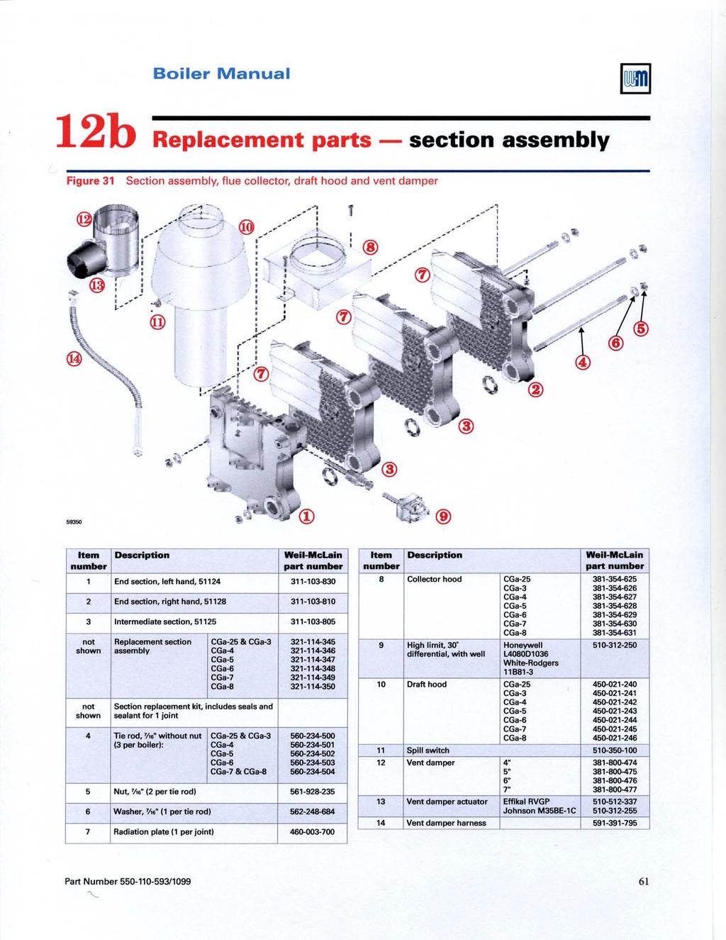
61
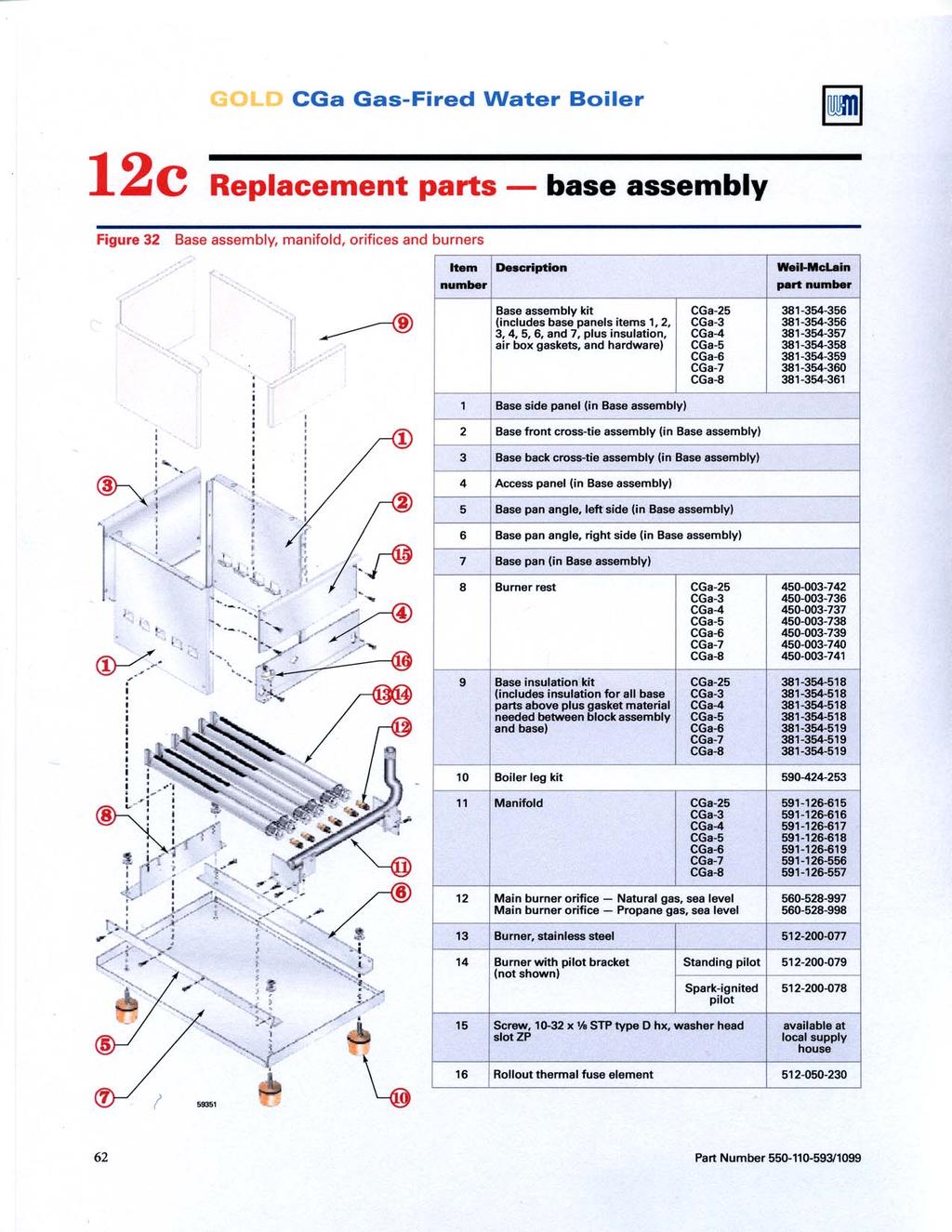
62
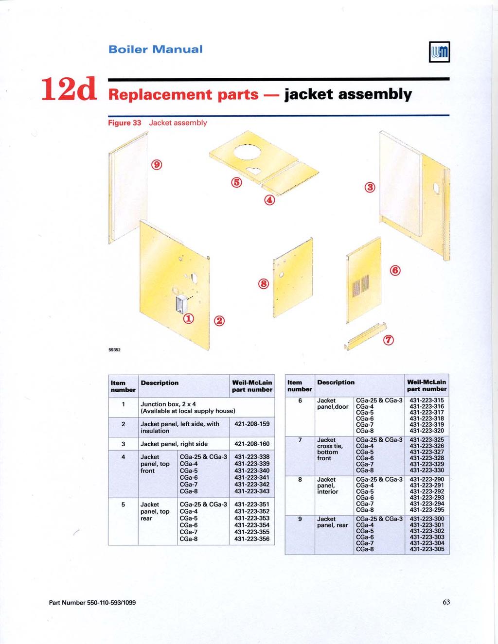
63
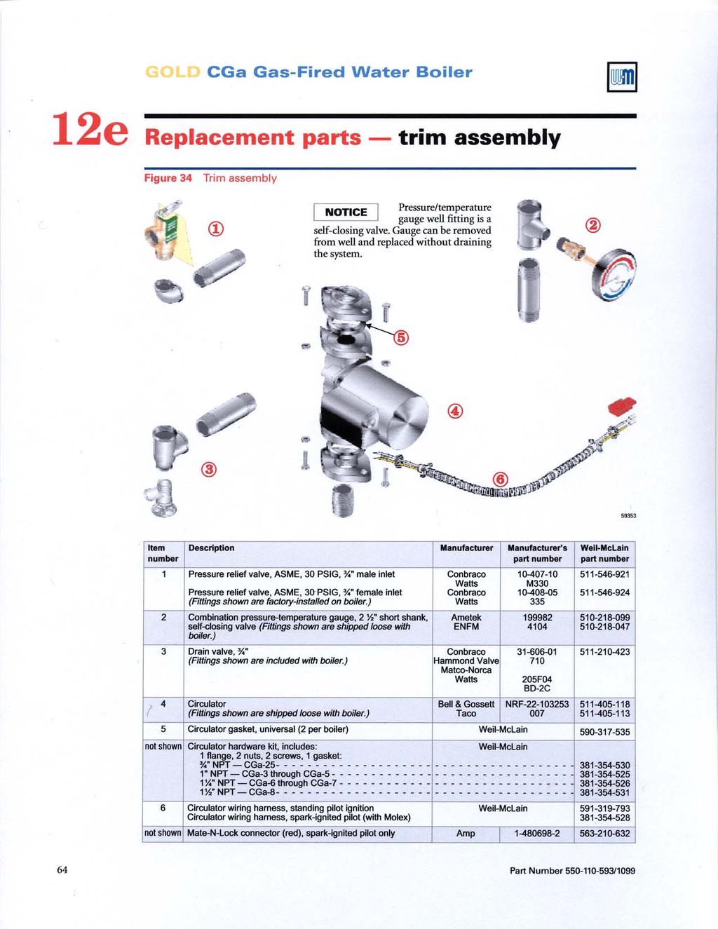
64
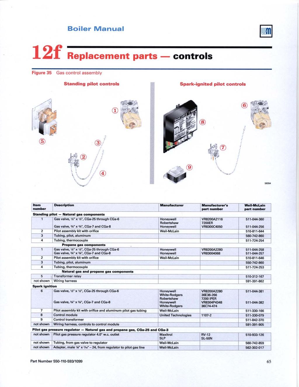
65
GOLD CGs. Boiler Manual. Gas-Fired Water Boilers. Maintenance Parts. Installation Startup
 GOLD CGs Gas-Fired Water Boilers Boiler Manual Installation Startup Maintenance Parts This manual must only be used by a qualified heating installer/service technician. Before installing, read all instructions,
Contents. Hazard definitions
 GWA Gas-Fired Water Boilers Boiler Manual Contents Page 1 Prepare boiler location... 2 2 Prepare boiler... 6 3 Install water piping... 10 4 Install gas piping... 13 5 Field wiring... 14 6 Start-up... 15
Contents. Hazard definitions
 GWA Series 2 Gas-Fired Water Boilers Boiler Manual Contents Page 1 Prepare boiler location...2 2 Prepare boiler...6 3 Install water piping...10 4 Install gas piping...13 5 Field wiring...14 6 Start-up...15
Contents. Hazard definitions
 GWS Gas-Fired Water Boilers Boiler Manual Contents Page 1 Prepare boiler location... 2 2 Prepare boiler... 8 3 Install water piping... 9 4 Venting and combustion air... 12 5 Gas piping... 12 6 Field wiring...
User s Information Manual
 User s Information Manual Series 2 Models 1000-2000 MBH Commercial Condensing Gas-fired water boilers If the information in this manual is not followed exactly, a fire or explosion may result, causing
Contents. Hazard definitions
 GWS-090E Gas-Fired Water Boiler Boiler Manual Contents Page 1 Prepare boiler location...2 2 Prepare boiler...8 3 Install water piping...9 4 Venting and combustion air...12 5 Gas piping...12 6 Field wiring...13
User s Information Manual
 TM User s Information Manual Commercial Condensing Gas-fired water boilers If the information in this manual is not followed exactly, a fire or explosion may result, causing property damage, personal injury
User s Information Manual
 User s Information Manual CONDENSING GAS BOILER 220/299/300/399 If the information in this manual is not followed exactly, a fire or explosion may result, causing property damage, personal injury or loss
GOLD. User s Information Manual. Water Boiler Series 4
 GV Water Boiler Series 4 User s Information Manual If the information in this manual is not followed exactly, a fire or explosion may result, causing property damage, personal injury or loss of life. Do
GOLD CGt. User s Information Manual. Natural gas-fired water boiler with tankless heater
 TM GOLD CGt Natural gas-fired water boiler with tankless heater User s Information Manual If the information in this manual is not followed exactly, a fire or explosion may result, causing property damage,
User s Information Manual
 User s Information Manual Series 3 Models 550 and 750 MBH Commercial Condensing Gas-fired water boilers If the information in this manual is not followed exactly, a fire or explosion may result, causing
Aqua Balance. User s Information Manual. WMB-155C Wall Mount Gas-Fired Combination Boiler Heating and Domestic Hot Water
 Aqua Balance WMB-155C Wall Mount Gas-Fired Combination Boiler Heating and Domestic Hot Water User s Information Manual * Low Lead Content If the information in this manual is not followed exactly, a fire
Contents. Hazard definitions
 Hazard definitions GW I Series 2 Gas-Fired Water Boilers Boiler Manual Contents Page 1 Prepare boiler location...2 2 Prepare boiler...6 3 Vent installation...7 4 Install water piping...13 5 Install gas
Page. Hazard definitions
 G SA Gas-Fired Steam Boilers Boiler Manual Contents Page 1 Prepare boiler location...2 2 Prepare boiler...8 3 Install piping...11 4 Install controls...14 5 Install gas piping...15 6 Field wiring...16 7
GWC. User s Information Manual. Gas-Fired Water Boilers. Model
 Model GWC Gas-Fired Water Boilers User s Information Manual If the information in this manual is not followed exactly, a fire or explosion may result, causing property damage, personal injury or loss of
User s Information Manual
 User s Information Manual Gas-Fired Water Boilers With or without Aqua Logic (CWH) Now available Matching High Performance Companion Water Heater (Unit sold separately) If the information in this manual
User s Information Manual
 Gas-fired Water boiler Series 2 NOTICE: Series 1/Series 2 identification Read the boiler rating plate to determine the series number. The rating plate is located on the right side of the boiler. User s
Contents. Hazard definitions
 GSA Gas-Fired Steam Boilers Boiler Manual Contents Page 1 Prepare boiler location... 2 2 Prepare boiler... 6 3 Install piping... 9 4 Install controls... 11 5 Install gas piping... 12 6 Field wiring...
EG/PEG/EGH. Boiler Manual. Series 5 Gas-Fired Boilers. Installation Startup. Maintenance Parts EG PEG EGH. Control Supplement and Gas Control Parts
 EG/PEG/EGH Series 5 Gas-Fired Boilers Boiler Manual Installation Startup Maintenance Parts EG PEG For additional information, refer to... Control Supplement and Gas Control Parts for EG/PEG Natural gas
User s Information Manual
 CGa Series 2, CGi Series 3, EG Series 5, EGH Series 4, LGB Series 2, PEG Series 5 Gas-Fired Boilers User s Information Manual INSTALLER: Please take time to review this User s information Manual with the
ProLine XE Combi Boiler
 100298581_2000552611_Rev A ProLine XE ProLine XE User Manual Models: 110-150 - 199 If the information in this manual is not followed exactly, a fire or explosion may result causing property damage, personal
GOLD. Venting Supplement. Water Boiler Series 3 & 4. for 3" venting
 GOLD GV Water Boiler Series 3 & 4 Venting Supplement for 3" venting Special gas vent system vent and combustion air supplement for 3" diameter venting. The following manufacturers AL29-4C Stainless Steel
Venting Supplement Saf-T Vent 3" venting Special gas vent system vent and combustion air supplement for 3" diameter venting Hazard definitions
 GOLD GV Water Boiler Series 3 & 4 Venting Supplement 3" venting Special gas vent system vent and combustion air supplement for 3" diameter venting Heat-Fab, Inc. AL29-4C Stainless Steel Special Gas Vent
User s Information Manual
 User s Information Manual Gas-fired water boilers Series 4 Featuring Flexibility Series 4 If the information in this manual is not followed exactly, a fire or explosion may result, causing property damage,
User s Information Manual
 CGa, CGi, CGs, EG, EGH, LGB, PEG, PFG Gas-Fired Boilers User s Information Manual If the information in this manual is not followed exactly, a fire or explosion may result, causing property damage, personal
User s Information Manual Models:
 FB-USER Rev C User s Information Manual Models:1.5-5.0 WARNING: If the information in these instructions is not followed exactly, a fire or explosion may result causing property damage, personal injury
GOLD GV. Venting Supplement for 3 venting. Water Boiler Series 3 & 4
 GOLD GV Water Boiler Series 3 & 4 Venting Supplement for 3 venting Special gas vent system vent and combustion air supplement for 3 diameter venting. The following manufacturers AL29-4C Stainless Steel
GOLD GV. Venting Supplement. Water boiler Series 3. Special gas vent system vent and combustion air supplement. Hazard definitions.
 GOLD GV Water boiler Series 3 Venting Supplement Special gas vent system vent and combustion air supplement ProTech Systems AL29-4C Stainless Steel Special Gas Vent System may be used in new installations
LGB Gas fired boiler
 LGB Gas fired boiler Control Supplement LGB-5 Series 2 Propane gas CSD-1 Control System Part Number 550-110-682/0304 Please read this page first Hazard definitions To the installer... The following terms
Boiler Manual. Gas-fired water boilers. Featuring. Flexibility
 Gas-fired water boilers Featuring Flexibility Boiler Manual This manual must only be used by a qualified heating installer/service technician. Read all instructions, including this manual and all other
WHAT TO DO IF YOU SMELL GAS
 GSA Gas-Fired Steam Boilers User s Information Manual Hazard definitions Hazards that will cause severe personal injury, death or substantial property damage. Hazards that can cause severe personal injury,
User s Information Manual Models:
 FB-USER_100161014_2000004599 Rev F User s Information Manual Models: 2500-6000 WARNING: If the information in these instructions is not followed exactly, a fire or explosion may result causing property
Residential Gas Hybrid Water Heater
 Residential Gas Hybrid Water Heater USER S INFORMATION MANUAL WGRGH20NG75F / WGRGH20NG76F / WGRGH20NG100F WGRGHNG75F / WGRGHNG76F / WGRGHNG100F Models* *A suffix of LP denotes propane gas NOTICE: Westinghouse
Universal Fire Tube Boiler Wall Mount Models
 Universal Fire Tube Boiler Wall Mount Models USER S INFORMATION MANUAL Models WBRU**80W / 100W / 120W / 140W / 175W / 199W **NG denotes Natural Gas Model, LP Denotes Propane Model Heat Exchanger Bears
MC Series Gas-Fired Heating Appliance
 MC Series Gas-Fired Heating Appliance USER S INFORMATION MANUAL MC Series Models MC50 / MC80 MC99 / MC120 NOTICE: HTP reserves the right to make product changes or updates without notice and will not be
Tankless Water Heater
 Tankless Water Heater USER S INFORMATION MANUAL Models WGRT**150 / WGRT**199 / WGRTC**199 **A suffix of LP denotes propane gas **A suffix of NG denotes natural gas NOTICE: Westinghouse reserves the right
Boiler Manual. Commercial Condensing Gas-fired water boilers
 TM Commercial Condensing Gas-fired water boilers Boiler Manual This manual must only be used by a qualified heating installer/service technician. Read all instructions, including this manual and all other
User s Information Manual
 User s Information Manual Gas-Fired Storage Water Heater, Tankless Water Heater, Heating Appliance, and Combination Appliance Models IF THE INFORMATION IN THIS MANUAL IS NOT FOLLOWED EXACTLY, A FIRE OR
Elite. User s Information Manual. Elite and Elite VWH* All Models
 Elite User s Information Manual Elite and Elite VWH* All Models Heat Exchanger Bears the ASME H Stamp IF THE INFORMATION IN THIS MANUAL IS NOT FOLLOWED EXACTLY, A FIRE OR EXPLOSION MAY RESULT, CAUSING
User s Information Manual Lynx Direct-Vent Sealed Combustion Condensing Boiler Model LX-90, LX-120, LX-150
 Residential Gas fired Hot Water Boilers User s Information Manual Lynx Direct-Vent Sealed Combustion Condensing Boiler Model LX-90, LX-120, LX-150 FOR YOUR SAFETY: Before operating this boiler, READ this
User s Information Manual Models:
 KBII-USER Rev F User s Information Manual Models: 81-286 If the information in this manual is not followed exactly, a fire or explosion may result causing property damage, personal injury or loss of life.
Gas Fired Residential Combi Boiler Floor and Wall Mount Models
 Gas Fired Residential Combi Boiler Floor and Wall Mount Models USER S INFORMATION MANUAL Models WBRC**140W WBRC**199W WBRC**140F WBRC**199F ** NG Refers to Natural Gas Operation LP Refers to Propane Gas
WHAT TO DO IF YOU SMELL GAS
 GOLD GV Water boiler Series 3 User s information manual If the information in this manual is not followed exactly, a fire or explosion may result, causing property damage, personal injury or loss of life.
User s Information Manual Models:
 WBII-USER Rev D User s Information Manual Models: 51-211 If the information in this manual is not followed exactly, a fire or explosion may result causing property damage, personal injury or loss of life.
Vent Supplement Ultra-80, -105, -155, -230 & -310
 Gas-fired water boiler Vent Supplement Ultra-80, -105, -155, -230 & -310 Installation of: Vent piping Air piping with This document must only be used by a qualified heating installer/service technician.
Boiler Manual. Oil-Fired Water Boilers. Maintenance Parts. Installation Startup
 Oil-Fired Water Boilers Boiler Manual Installation Startup Maintenance Parts This manual must only be used by a qualified heating installer/service technician. BEFORE installing, read all instructions
Boiler Manual. Series 3 Oil-Fired Water Boiler. Maintenance Parts. Installation Startup
 Series 3 Oil-Fired Water Boiler Boiler Manual Installation Startup Maintenance Parts This manual must only be used by a qualified heating installer/service technician. Read all instructions, including
LGB. Control Supplement. Gas fired boiler. Universal Control System. Series 2 Propane gas. Contents
 LGB Gas fired boiler Control Supplement LGB-6 to LGB-23 Series 2 Propane gas Universal Control System Contents I. New installation... 2 II. Existing installation... 4 III. Gas piping... 5 IV. Wiring...
User s Information Manual Models:
 SYNC-USER Rev E User s Information Manual Models: 1.0-1.3-1.5 WARNING: If the information in these instructions is not followed exactly, a fire or explosion may result causing property damage, personal
Boiler Manual. Gas-Fired Water Boilers. Maintenance Parts. Installation Startup
 Gas-Fired Water Boilers Boiler Manual Installation Startup Maintenance Parts This manual must only be used by a qualified heating installer/service technician. BEFORE installing, read all instructions
Internet Version for Reference Only INDUCED DRAFT COMMERCIAL WATER HEATERS SUPPLEMENT INSTRUCTIONS TO PART #
 INDUCED DRAFT COMMERCIAL WATER HEATERS SUPPLEMENT INSTRUCTIONS TO PART #238-39387-00 THIS INSTRUCTION SUPPLEMENT IS ONLY INTENDED TO GIVE INSTALLATION INSTRUCTIONS AND INFORMATION RELATED TO THE INDUCED
If the information in this manual is not followed exactly, a fire or explosion may result causing property damage, personal injury or loss of life.
 prestige User s Information Manual If the information in this manual is not followed exactly, a fire or explosion may result causing property damage, personal injury or loss of life. FOR YOUR SAFETY Do
WHAT TO DO IF YOU SMELL GAS
 AHE AHE SERIES 4 Direct Vent Wall-Mounted Boilers User s Information Manual If the information in this manual is not followed exactly, a fire or explosion may result, causing property damage, personal
Boiler Manual. Gas-fired water boilers Series 3. Installation Startup. Maintenance Parts. Featuring. Flexibility
 Gas-fired water boilers Series 3 Featuring Flexibility Boiler Manual Installation Startup Maintenance Parts This manual must only be used by a qualified heating installer/service technician. Read all instructions,
User s Information Manual Models:
 100287990_2000545748_Rev B User s Information Manual Models: 56-400 If the information in this manual is not followed exactly, a fire or explosion may result causing property damage, personal injury or
User s Information Manual Models: WH
 WH-USER Rev F User s Information Manual Models: WH 55-399 If the information in this manual is not followed exactly, a fire or explosion may result causing property damage, personal injury or loss of life.
Boiler Manual. Series 3 Oil-Fired Water Boilers. Installation Maintenance Parts
 Series 3 Oil-Fired Water Boilers Boiler Manual Installation Maintenance Startup Parts This manual must only be used by a qualified heating installer/service technician. BEFORE installing, read all instructions
GWS. Venting Manual. Gas-Fired Water Boilers. Hazard definitions. Contents. Venting method definitions
 GWS Gas-Fired Water Boilers Venting Manual Hazard definitions Contents Page Hazards that will cause severe personal injury, death or substantial property damage. Hazards that can cause severe personal
EG/PEG/EGH. Boiler Manual. Series 5 Gas-Fired Boilers. Installation Startup. Maintenance Parts EG PEG EGH. Control Supplement and Gas Control Parts
 EG/PEG/EGH Series 5 Gas-Fired Boilers Boiler Manual Installation Startup Maintenance Parts EG PEG For additional information, refer to... Control Supplement and Gas Control Parts for EG/PEG Natural gas
Please read before proceeding Indicates presence of hazards that will cause severe personal injury, death or substantial property damage.
 Contents Please read before proceeding... 3 1 2 3 4 5 6 7 8 9 10 11 12 13 14 15 Prepare boiler location... 4-7 Venting... 8-13 Prepare boiler... 14 Water piping... 15-17 Gas piping... 18 Field wiring...
Installation. Manual. Installation. Startup Maintenance Parts WARNING
 Installation Manual Installation Startup Maintenance Parts MH18082 WARNING This manual must only be used by a qualified heating installer/service technician. Read all instructions in this manual before
If the information in this manual is not followed exactly, a fire or explosion may result causing property damage, personal injury or loss of life.
 If the information in this manual is not followed exactly, a fire or explosion may result causing property damage, personal injury or loss of life. FOR YOUR SAFETY Do not store or use gasoline or other
NOTICE. If the information in this manual is not followed exactly, a fire or explosion may WARNING FOR YOUR SAFETY
 Warranty Registration Card must be filled out by the customer and mailed within thirty (30) days of installation in order to gain warranty coverage. When receiving the PRESTIGE Solo unit, any claims for
Boiler Manual. Series 3 Oil-Fired Water Boilers. Installation Maintenance Parts
 Series 3 Oil-Fired Water Boilers Boiler Manual Installation Maintenance Startup Parts This manual must only be used by a qualified heating installer/service technician. BEFORE installing, read all instructions
Boiler Manual. Wall Mount Gas-Fired Water Boilers 70/110/155
 Wall Mount Gas-Fired Water Boilers 70/110/155 Boiler Manual This manual must only be used by a qualified heating installer/service technician. Read all instructions, including this manual and all other
User s Information Manual Models: Starting Serial #H05H
 Models: 80-500 Starting Serial #H05H10003637 If the information in this manual is not followed exactly, a fire or explosion may result causing property damage, personal injury or loss of life. This appliance
Installation & Operation Manual Models:
 KBXII-I-O Rev H Installation & Operation Manual Models: 400-801 This manual must only be used by a qualified heating installer / service technician. Read all instructions, including this manual and the
Installation & Operation Manual Models:
 AWII-I-O Rev G Installation & Operation Manual Models: 151-801 : If the information in this manual is not followed exactly, a fire or explosion may result causing property damage, personal injury or loss
Do not use this vent pipe or fittings for venting incinerators of any kind.
 ! CAUTION! Do not use this vent pipe or fittings for venting incinerators of any kind. C.S.A. Certified For Natural Gas Or Propane Tested For 100 LBS. ASME Working Pressure For correct installation of
Boiler Manual. Series 1 Models Commercial Condensing. Maintenance Parts. Installation Startup
 Series 1 Models 750-1100 Commercial Condensing Boiler Manual Installation Startup Maintenance Parts This manual must only be used by a qualified heating installer/service technician. Read all instructions,
MC Series Gas-Fired Circulating Heater
 MC Series Gas-Fired Circulating Heater INSTALLATION START-UP MAINTENANCE PARTS Models MC50 / MC80 MC99 / MC120 When installing models manufactured after July 7, 2008, you will notice additional selections
User s Information Manual Models:
 KBXII-USER_100161491_2000013415_Rev H User s Information Manual Models: 400-801 If the information in this manual is not followed exactly, a fire or explosion may result causing property damage, personal
Boiler Manual. Oil-Fired Steam Boilers. Maintenance Parts. Installation Startup
 Oil-Fired Steam Boilers Boiler Manual Installation Startup Maintenance Parts This manual must only be used by a qualified heating installer/service technician. BEFORE installing, read all instructions
Installation. Manual. Installation. Startup Maintenance Parts NOTICE WARNING
 Installation Manual Installation Startup Maintenance Parts NOTICE When installing Models manufactured after July 7th, 2008, you will notice additional selections on the Installer Menu of the Control that
Installation & Operation Manual Models: Starting Serial #H07H
 Models: 80-285 Starting Serial #H07H10040039 This manual must only be used by a qualified heating installer / service technician. Read all instructions, including this manual and the Knight Boiler Service
USER S INFORMATION MANUAL
 USER S INFORMATION MANUAL HOT WATER HEATING BOILERS DOMESTIC WATER HEATERS 150,000-300,000 Btu/hr MODELS EB-EWU-02 IMPORTANT INSTALLER - AFFIX INSTALLATION MANUAL ADJACENT TO THE BOILER CONSUMER - RETAIN
AquaBalance SERIES 2 WALL MOUNT GAS-FIRED WATER BOILER Boiler Manual. Contents. Page. Hazard definitions
 Aqua Balance 80/120/155 Series 2 Wall Mount Gas-Fired Condensing Boilers Combi and Heating Only Models Boiler Manual Installation Startup Maintenance Parts Quick Start Guide Pages 69 & 70 * CSA - Low Lead
Installation Instructions T 9822 Gas Dryer. en - US, CA. To prevent accidents
 Installation Instructions T 9822 Gas Dryer To prevent accidents en - US, CA and appliance damage read these instructions before installation or use. M.-Nr. 07 431 110 2 WARNING For your safety the information
Outdoor Armor Water Heater Installation & Operation Manual Models:
 OAW-I-O Rev D : If the information in this manual is not followed exactly, a fire or explosion may result causing property damage, personal injury or loss of life. Outdoor Armor Water Heater Installation
CER Series 2. Installation Instructions. Electric-Hydronic Boilers. Installer
 CER Series 2 Electric-Hydronic Boilers Installation Instructions Installer Read all instructions before installing. Follow all instructions in proper order to prevent personal injury or death. Consider
GENERAL BASIC INSTALLATION INSTRUCTIONS INDIRECT GAS FIRED WATER HEATERS PARKER BOILER CO.
 GENERAL BASIC INSTALLATION INSTRUCTIONS INDIRECT GAS FIRED WATER HEATERS PARKER BOILER CO. GBI 210 3C For a proper installation and in order to receive the best in operating life and efficiency from your
Aqua Balance. Boiler Manual WMB-80/120/155. Wall Mount Gas-Fired Condensing Boilers Combi and Heating Only Models. Quick Start Guide Pages 3 & 4
 Aqua Balance WMB-80/120/155 Wall Mount Gas-Fired Condensing Boilers Combi and Heating Only Models Boiler Manual Installation Startup Maintenance Parts Quick Start Guide Pages 3 & 4 * CSA - Low Lead Content
Installation & Operation Manual Models:
 KBII-I-O Rev N Installation & Operation Manual Models: 81-286 This manual must only be used by a qualified heating installer / service technician. Read all instructions, including this manual and the Knight
EGH Series 5. Control Supplement. EGH-105 to EGH-125 Natural gas CSD-1 control system
 EGH Series 5 Gas-Fired Boilers Control Supplement EGH-105 to EGH-125 Natural gas CSD-1 control system For propane boilers, install EGH liquefied petreoleum (propane) gas conversion kit in addition to following
National Comfort Products 539 Dunksferry Road Bensalem, PA (215) Fax: (215)
 Fax: (215)") National Comfort Products 539 Dunksferry Road Bensalem, PA 19020 (215) 244-1400 1-800-523-7138 Fax: (215) 639-1674 14299575-10/29/2014 NOTE: These installation and maintenance instructions should be left
National Comfort Products 539 Dunksferry Road Bensalem, PA 19020 (215) 244-1400 1-800-523-7138 Fax: (215) 639-1674 14299575-10/29/2014 NOTE: These installation and maintenance instructions should be left
Installation & Operation Manual Models:
 KBX-I-O Rev D Installation & Operation Manual Models: 399-800 This manual must only be used by a qualified heating installer / service technician. Read all instructions, including this manual and the Knight
Installation & Operation Manual Models: WH
 WH-I-O Rev O Installation & Operation Manual Models: WH 55-399 This manual must only be used by a qualified heating installer / service technician. Read all instructions, including this manual and the
GENERAL BASIC INSTALLATION INSTRUCTIONS DIRECT FIRED HOT WATER BOILERS PARKER BOILER CO.
 GENERAL BASIC INSTALLATION INSTRUCTIONS DIRECT FIRED HOT WATER BOILERS PARKER BOILER CO. GBI 201-5 3C For a proper installation and in order to receive the best in operating life and efficiency from your
User s Information Manual Models: 400, 500, 600, 725, & 850
 FTXL-USER_100059366_2000005005_ Rev D User s Information Manual Models: 400, 500, 600, 725, & 850 If the information in this manual is not followed exactly, a fire or explosion may result causing property
*p * HWC4 Model THRU-THE-WALL UNIT INSTALLATION INSTRUCTIONS WARNING WARNING WARNING WARNING CAUTION CAUTION TABLE OF CONTENTS
 HWC4 Model THRU-THE-WALL UNIT INSTALLATION INSTRUCTIONS Save these instructions for future reference Improper installation, adjustment, alteration, service, or maintenance can cause injury or property
Series 2 Wall Mount Gas-Fired Water Boilers 70/110/155
 Series 2 Wall Mount Gas-Fired Water Boilers 70/110/155 Installation Startup Maintenance Parts This manual must only be used by a qualified heating installer/service technician. Read all instructions, including
FreeStyle Wall Mount Gas-Fired Condensing Boilers Combi & Heat Only Models
 FreeStyle Wall Mount Gas-Fired Condensing Boilers Combi & Heat Only Models 80/120/155 Series 2 * Low Lead Content Boiler Manual Installation Startup Maintenance Parts Quick Start Guide Pages 69 & 70 Available
Direct Exhaust Venting Kit Instructions
 CONDENSING GAS BOILER 220/299/300/399 Direct Exhaust Venting Kit Instructions Evergreen 220/299/300/399 Kit part number 383-500-769 STOP! Read before proceeding Hazard definitions The following defined
Mod Con INSTALLATION START-UP MAINTENANCE PARTS. Mod Con Models 300 / 500 / 850 LP / HL / LPHL
 Mod Con INSTALLATION START-UP MAINTENANCE PARTS Mod Con Models 300 / 500 / 850 LP / HL / LPHL This manual must only be used by a qualified heating installer/service technician. Read all instructions in
SUPER HIGH EFFICIENCY WATER HEATERS SUPPLEMENT TO INSTRUCTION MANUAL P/N (Replaces pg. 2 in instruction manual.) CONGRATULATIONS!
 CONGRATULATIONS!") SUPER HIGH EFFICIENCY WATER HEATERS SUPPLEMENT TO INSTRUCTION MANUAL P/N 238-44219-00 (Replaces pg. 2 in instruction manual.) CONGRATULATIONS! You have just purchased one of the finest water heaters on
SUPER HIGH EFFICIENCY WATER HEATERS SUPPLEMENT TO INSTRUCTION MANUAL P/N 238-44219-00 (Replaces pg. 2 in instruction manual.) CONGRATULATIONS! You have just purchased one of the finest water heaters on
PRESTIGE Solo. Installation & Maintenance Manual
 Installation & Maintenance Manual PRESTIGE Solo PA 80, 110, 155, 175, 250, 299, 399 Warranty Registration Card must be filled out by the customer and mailed within thirty (30) days of installation in order
Munchkin Gas-Fired Boiler
 Munchkin Gas-Fired Boiler INSTALLATION START-UP MAINTENANCE PARTS Models T50M / T80M 80M / 140M / 199M / 399M Heat Exchanger Bears the ASME Stamp When installing models manufactured after July 7, 2008,
WATER HEATERS / BOILERS GSB8-E. Gas-Fired Steam Boiler PRODUCT SPECIFICATIONS. AFUE up to 82.7% Heating Input 75,000 to 299,000 Btuh GSB E
 WATER HEATERS / BOILERS -E PRODUCT SPECIFICATIONS Gas-Fired Steam Boiler Bulletin No. 20653 September 202 Supersedes Bulletin No. 20263 AFUE up to 82.7% Heating Input 75,000 to 299,000 Btuh MODEL NUMBER
SuperStor Contender Indirect Fired Water Heater
 SuperStor Contender Indirect Fired Water Heater INSTALLATION START-UP MAINTENANCE PARTS SuperStor Contender Water Heater Models SSC-35 / SSC-50 / SSC-80 / SSC-119* *NOTE: A suffix of S denotes Solar Model
Installation & Operation Manual Models:
 Models: 50-210 This manual must only be used by a qualified heating installer / service technician. Read all instructions, including this manual and the Knight Wall Mount Service Manual, before installing.