Ventilation Engineering Analysis. Schust Engineering Project #1845
|
|
|
- Phoebe Rogers
- 5 years ago
- Views:
Transcription
1 Ventilation Engineering Analysis Schust Engineering Project #1845
2 September 27 Industrial Facility Attn: Industrial Facility Representative Re: Engineering Analysis for dust collection and general ventilation Schust Engineering Inc. is pleased to present the following engineering analysis relating to the dust collection and general ventilation of your facility. The study was implemented in response to concerns about employee contact with airborne particulate, ineffective performances of existing ventilation equipment, and an ongoing decrease of the air quality. The study focuses on the four (4) areas throughout your facility; LCF, Main Bay Sand Reclaim System, Main Bay No Bake System, and the Cleaning Room. The desired end result of the study is to maximize effluent capture efficiency and improve the air quality. The target is to utilize as much existing ventilation equipment as possible. The study is based on field audit of the existing ventilation equipment, production operations, and information supplied to us by the plant. Overall exhaust air volume measurements were taken throughout each collector system (where available). This airflow data was then used in comparison to volume parameters based on duct designs for the existing dust collector system. Based on design parameters of the exhaust hooding and measured air volumes, we were then able to determine if the best achievable emissions capture was being implemented, or if modifications were required. We look forward to your feedback on the report. Please do not hesitate to call regarding any comments or questions that you may have. I can be reached at (260) Sincerely, Thad Wilburn Project Engineer 1845D-1
3 Table of Contents Introduction... 3 Large Casting Facility (LCF)... 5 LCF General Building... 5 Flask-Less Mold Area...7 No Bake Mold Area...11 Melting and Tap Area Scrap Bay and Charge Area Pouring/ Mold Cooling Area Shakeout Area Pattern Storage Area Sand Reclaim Area Dust Collector Recommendations LCF General Ventilation LCF Summarized Recommendations LCF Budgetary Pricing Main Bay Sand Reclaim System Main Bay Sand Reclaim Budgetary Pricing...64 Main Bay No Bake Mold Machine Main Bay No Bake Budgetary Pricing...69 Appendix Cleaning Room... N/A 1845D-2
4 Introduction The following report presents an engineering analysis of the requested individual problem areas at the facility along with an itemized list of recommendations regarding the upgrading of the Air Pollution Control (APC) system. The individual areas, covered in separate sections in this report, are the LCF, Main Bay Sand Reclaim System, Main Bay No Bake Mold System and Cleaning Room Areas. Our goal is to design appropriate systems and methods to eliminate the need to use respirators throughout each facility. The audit used both visual observations and measured field data on the existing production and APC equipment. We observed the normal production operations for each area making notes and taking field measurements. The principles of Local-Exhaust ventilation, in many cases, are the core of proper fume capture at an emissions source. Local-Exhaust principles focus on capturing fumes at the point of generation, thus not allowing the fumes to migrate into the general plant environment which reduces the chance of exposure to the work force by the contaminates. By following these principles, the amount of exhaust air volume required to control an emission source can be minimized. As such, Local-Exhaust ventilation will be recommended whenever possible. If the preferred method of Local-Exhaust ventilation is not practical, the secondary method to reduce high levels of emissions exposure is to use General-Exhaust ventilation. General- Exhaust ventilation is use to remove contaminants generated in space by flushing out a given space with large quantities of air. When General-Exhaust ventilation is used for contaminate control (Dilution System), enough outside air must be mixed with the contaminant air to reduce the concentration of exposure level to achieve a safe and healthy work environment. A supply-air system is generally used in conjunction with General-Exhaust ventilation to replace the air exhausted. This strategy will be used throughout the analysis to solve the airborne particulate, smoke and fume problems of the facility. Existing plant APC systems will be considered first as the solution with purchasing new equipment second. The continued lowering of the allowable personnel exposure levels increases the need to have State of the Art control systems in place, as well as close supervision and training of employees to assure that the ventilation systems are used properly. The installation of additional ventilation equipment is not a guarantee that the emissions problem will be completely solved. Evaluation of work methods, employee use of ventilation controls, and on going monitoring of the system performance will be necessary to meet the mandated regulations. Recommendations are based upon the production operation methods observed during the audit of the facility. Although we shall present recommendations to effectively control the emissions during various phases of production, the question should be asked, Can the emission source be reduced or the employee exposure eliminated by process changes rather than adding more ventilation? 1845D-3
5 The cost of APC equipment continues to escalate and restrictions on plant emission sources now require additional filtering controls rather than discharging to atmosphere. When evaluating action plans to conform to governmental regulations, method and equipment improvements that may result in productivity improvements or labor savings should also be considered. 1845D-4
6 LCF GENERAL DESCRIPTION Large Casting Facility (LCF) The LCF or Large Casting facility produces large castings that require; large overhead cranes or forklifts to transport them, considerable amount of real estate for staging, and allot of flexibility to maneuver them throughout the plant. As a result, the LCF building is rather large at approximately wide x long (100,750 ft 2 ) and completely open on the inside to accommodate the handling of these large castings. Per our field observations of the LCF production process, there are basically seven (7) different production areas within this building. Please reference Appendix, drawing A. Mold Area Melt/ Tap Area Scrap Bay/ Charge Area Pouring and Mold Cooling Area Shake-out Area Sand Reclaim Area Pattern Storage Area Molds are produced in two (2) separate areas. Each area produces a different type or style of mold based on the production equipment in that area. From the molding areas, the molds are transported to the mold cooling and pouring area by overhead cranes and/or forklifts. The molds are staged directly on the foundry floor, waiting to be poured. While the molds are being produced, the furnaces have been charged with scrap material and are in the process of melting. Once the furnaces have completed the melt, tap, and inoculation phases, the overhead crane will transport the pouring ladle to the molds located in the mold cooling areas and pour the molten metal into the molds. After the molds have cooled, the overhead crane transports the molds from the cooling areas to the shakeout area located at the opposite end of the LCF Building. The overhead crane places the molds onto a strip grate and shakeout deck, where the mold breaks and separates from the casting. The mold sand falls through the shakeout deck and strip grates and enters the sand reclaim system, located in the pit below the shakeout area. The sand reclaim system is used to break up the sand molds back into sand grains as well as cool the sand prior to entering the (2) storage silos. From the storage silos, the reclaimed sand is conveyed and introduced back into the molding process. During our field audit, Schust Engineering observed each production process very carefully to determine which areas are contributing to the fugitive emissions that linger throughout the building. The following list is categorized from the worst to the least process that generates fugitive emissions. Emissions from the Tap and Inoculation process. Emissions from the Shake-out process (Shakeout Deck & Strip Grate) Emissions from the Weigh & Charge process (Weigh & Charge Conveyor) Emissions from the Pour process (Pouring metal from ladle into the molds) Emissions from the Sand Reclaim process (Pit Area) Emissions from the Molding process (Mixers) 1845D-5
7 The Tap and Inoculation processes are performed in front and sometimes adjacent to the two (2) furnaces. During both of these processes, a volatile reaction occurs, producing a significant amount of smoke and fume that naturally draft upward at high velocities. Currently, there is no ventilation to capture or contain these fugitive emissions. The smoke and fume engulfs the Melt area and even tends to linger and migrate throughout the surrounding areas well after the process has been completed. During the Shakeout process, when the mold separates from the casting, a large volume of smoke, fume, heat, and dust are generated. This process does have a large side draft hood that spans the entire length of the Shakeout Deck & Strip Grate. Per our observations, the hood was capturing some emissions that were trapped between the mold and the hood. However, the emissions on the opposite side and directly above the mold were escaping. It appears that the side draft hood does not have enough volume to reach out and capture the emissions on the far side of the shakeout deck. Once these fugitive emissions become airborne, they migrate eastward towards the furnace area. In the Charge area, the worst emissions are generated when the weigh feeder transfers the scrap metal onto the Charge feeder. When the weigh feeder initiates, an instant cloud of dust, from the scrap metal, engulfs the entire melt deck and furnace operators. Once this transfer is complete and the weigh feeder shuts off, the dust cloud tends to dissipate and migrate towards the furnace hoods. The pouring process takes place in the Pouring/ Mold Cooling areas, which are located in or near the center of the LCF building. The largest amount of emissions are generated when operators pour the metal from the ladle into the molds setting on the floor. Although this operation is performed in a short time, smoke, fume, and heat are released and naturally draft upward. After pouring is completed, a haze of smoke can be seen throughout this area. The majority of the Sand Reclaim system seemed to be performing fairly well, with the exception the Fluidized Cooling Conveyor, which is directly underneath the Shakeout deck. Particulate can be seen pulsating out of inlet and outlet of the Fluidized Cooling Conveyor. The Mold mixers have significant amounts of dust and sand build-up on and around the equipment and surrounding floor areas. When the operator initiates the mixers, emissions can be seen escaping from the transfer points on both mixer machines. These fugitive emissions migrate throughout each area and come in contact with the operators. Schust Engineering will now discuss the seven (7) production areas in more detail. Each production area will include, but not be limited to, a brief system description, comments on the existing equipment and emissions sources, and recommendations for ventilation. 1845D-6
8 As mentioned earlier, the LCF building has two (2) independent molding areas, located on the north side of the building. They are called Flask-less and No Bake. All of the molds generated for the LCF castings are made in one of these mold areas. FLASK-LESS MOLD AREA The Flask-less mold area is located between building column line #1 through #7 and between building column lines D & E. This area is approximately long x 30-0 wide with a total square footage of 4,170 ft 2. The Flask-less Mold area consist of the following process equipment: Sand Surge Hopper Bucket Elevator (1) 100 Ton Sand Silo (1) Slinger style Mixer Mold roller conveyors According to plant personnel, the existing surge hopper and bucket elevator are no longer used to transport the sand to the silo. Currently, the industrial facility utilizes a pneumatic pipe to transport the sand from sand trucks to the 100 Ton Sand Silo. From the silo, the sand dumps onto an incline belt that conveys the sand to the mixer head. As the sand enters the mixer, the resin binders are injected and mixed into the sand. After the mold flasks have been assembled on the roller conveyor, the operator will manually activate the mixer and fill the flask. Once the operator completes the fill, the mold is rolled towards the end of the roller conveyor. Once the mold has cured, then the operator will remove the flask from the mold. The mold has been completed and waits to be transported to the mold cooling area. The Flask-less molding equipment has one (1) 5,000 cfm Pulse Style Dust collector and duct system that was intended to exhaust different transfer points on the equipment. These points are as follows: Transfer from Bucket Elevator to Sand Silo Swivel connection between Silo and Incline belt. Tail End of the Incline Belt. Head End of Incline Belt (transfer from belt to mixer). 1845D-7
 Exhaust Tap (Disconnected)")

9 100 Ton Sand Silo Bucket Elevator/ Sand Silo Exhaust Tap (Disconnected) Incline Belt (Head End) Exhaust Tap Surge Hopper & Bucket Elevator no longer in use Swivel Connection Exhaust Tap Incline Belt & Mixer Incline Belt (Tail End) Exhaust Tap (Disconnected) Flask-less Mixer Photo # Flask-less Mold D.C. Manufacturer: Flex Kleen Model No. 58-BVS-36 No. Filters 36 Filter Size 6 Ø x 5-0 Rated Volume 5,000 ACFM Air / Cloth Ratio 17:1 A/C 8 Ø Main Duct Line 4 Ø Sand Pneumatic Transport Line. Flask-less Dust Collector Photo 1845D-8
10 Schust Engineering has reviewed and evaluated the Flask-less dust collector system. Some issues involved with our evaluation include; original system design specifications, existing physical condition of system, and current system operating performance. Assuming that the original duct exhaust taps were properly designed with a transport velocity of 4,000 fpm, the following table represents the existing system design exhaust volumes. Based on our calculations, the existing system was designed for approximately 1,400 CFM. During our audit, we noticed that the exhaust taps were disconnected from the Bucket Elevator to the Sand Silo transfer and the Tail End of the Incline Belt. We observed a significant amount of dust and sand on the equipment as well as the floor. All of the exhaust taps are performing poorly with evidence of emissions escaping from each exhaust point, even the ones where the duct is connected. In order to evaluate the performance of the Flask-less dust collector, Schust Engineering performed an airflow test at the main line of the dust collection system. The following table portrays our test results. Our test results indicate that the system is performing 52% below its original design. 1845D-9
11 Flask-less Mold Recommendations: 1. Remove existing ductwork and design, fabricate, and install new. The design of the exhaust ductwork shall be in accordance with SMACNA standards. The duct shall be sized for a transport velocity of 4,000 FPM. These exhaust points are pretty straightforward for the most part, with the exception of the Sand Silo. Due to the fact that this process is now introducing the sand pneumatically, air displacement becomes the main issue. Simply stated, air introduced into the sand silo must be exhausted at the same rate. The Industrial Ventilation Manual states the following: For Silo or Bin transfer points of Non-Toxic material. A typical design requires a 500 ft 3 /min hood or shroud be attached directly to the sand silo with a face velocity of not more than 500 ft/min. Care should be taken so that valuable product will not be pulled into the system. (Reference figure of the Industrial Ventilation Manual 22 nd Edition) For conveyor belt ventilation of dry dusty materials, allocate 700 ft 3 /min for belts between wide at transfer points. Approximately 350 ft 3 /min of additional exhaust will be required for chute to belt transfer greater than 3-0 fall on the backside of the transfer point. (Reference figure VS of the Industrial Ventilation Manual 22 nd Edition) Typical medium phase pneumatic transport systems will convey silica sand in a range of 3500 ft/min to 4000 ft/min. Transport Line = 4 Ø Q = V * A = 4000 ft/min *.087ft 2 = 350 ft 3 /min 500 ft 3 /min The design of the exhaust ductwork shall be in accordance with SMACNA standards. The exhaust taps shall be designed with typical square to round transitions mounted directly to the equipment, similar to what exists. The duct shall be sized for a transport velocity of 4,000 FPM. The following volume table will represent all the proposed required exhaust points for the Flask-less Mold Equipment. Please Note: Options for dust collectors to control these sources will be discussed later in this report. 1845D-10
12 NO BAKE MOLD AREA The No Bake Molding process is very similar to that of the Flask-less. The No Bake molds are usually larger in size and require an overhead crane to transport them, where as the Flask-less molds usually can be moved with forklifts. The No Bake Mold area consists of the following process equipment: (1) 300 Ton Sand Silo with Bin Vent Sand Heater (1) Slinger style Mixer Mold roller conveyors Again, industrial facility utilizes pneumatic conveying to transport the sand into a 300 Ton Sand Silo, located outside the building. The 300 Ton Sand Silo is equipped with a Dynamic Air Bin Vent mounted on top of the sand silo. The purpose of the Bin Vent is to filter and exhaust the air being pumped in from the pneumatic sand trucks. It appears that the bin vent is functioning properly and there are no signs of sand leakage or dusting problems. From the silo, the sand travels down a discharge chute and passes through the Sand Heater. From the heater, the sand discharges onto an incline belt that conveys the sand to the mixer head. After the mold flasks have been assembled on the roller conveyor, the operator will manually activate the mixer and fill the flask. Once the operator completes the fill, the mold is rolled towards the end of the roller conveyor. The flasks are not removed from the sand mold on this particular process; they will remain in tack until the end of the casting process. The No Bake process has a drying oven located at the tail end of the roller conveyor. According to plant personnel, this oven is no longer used in the process and will be disregarded in this report. The No Bake molding equipment has one (1) 1,900 cfm Pulse Style Bin Vent and duct system that was intended to exhaust different transfer points on the equipment. However, the duct system has been modified and some duct branches have been removed. The existing duct system had an 8 Ø main line that is now capped off. It appears that a 4 Ø line has been welded to the main line and is the only duct branch in operation. The 4 Ø duct routes to a dropout box that is suspended near the base of the sand silo. From the side of the dropout box, a 6 Ø (spiral) duct runs inside the building and connects to the sand heater. From the top of the box, there is another 4 Ø line that routes and connects to a plenum box located at the top of the 300 Ton Sand Silo. With exception of the Sand Heater and 300 Ton Silo, no other equipment located in this area is ventilated. The Mold mixer area has a significant amount of dust and sand build-up on and around the equipment. When the operator initiates the mixer, emissions can be seen escaping from the transfer points on the mixer head and the incline belt. We have noticed a high concentration of fugitive emissions that become airborne and migrate eastward affecting the majority of the molding area. 1845D-11


13 300 Ton Sand Silo w/ Dynamic Air Bin Vent 4 Ø Sand Silo Exhaust line # No Bake Dust Collector Manufacturer: Flex Kleen Model No. 58-BVS No. Filters 16 Filter Size 6 Ø x 5-0 Rated Volume 1,900 ACFM Air / Cloth Ratio 15:1 Dropout Box???? 6 Ø Sand Heater Exhaust Line 4 Ø Exhaust line 8 Ø Main Duct line - Capped No Bake Dust Collector Photo No Exhaust transfer point from Head End of Incline Belt to Mixer No Exhaust transfer point from Sand Heater to Incline Belt Mixer Sand Incline Belt Enclosed Mixer No Bake Mixer Photo 1845D-12
14 Schust Engineering s evaluation of the No Bake dust collection system is very similar to that of the Flask-less dust collection system: therefore, our comments and recommendations have been summarized. Dust collector is operating at poor volume performance. No Bake Dust collector measured volume = 105 CFM (Design 1,900 CFM) Dust collector is in poor physical condition. Ductwork is in poor condition. Branches been modified, removed, disconnected, and improperly designed as shown in No Bake dust collector photo. No exhaust ventilation for transfer points that emit dust. Flask Less Mixer Incline Belt head & tail end. No Bake Mold Recommendations 2. Remove existing ductwork and design, fabricate, and install new. The design of the exhaust ductwork shall be in accordance with SMACNA standards. The exhaust taps shall be designed with typical square to round transitions mounted directly to the equipment. The duct shall be sized for a transport velocity of 4,000 FPM. Following the same Industrial ventilation principles as described in Flask-less design, the following volume table will represent all the proposed required exhaust points for the No Bake Mold Equipment. Please Note: The Sand Silo exhaust tap has been excluded from this calculation. 1845D-13
15 As previously mentioned, the 300 Ton Sand Silo is equipment with a Bin Vent that appears to be functioning properly. However, maintenance and service on this bin vent can be very difficult and time consuming. If the industrial facility chooses to eliminate the bin vent, due to the difficulty of maintenance, Schust Engineering could allocate an additional 500 Ft 3 /min of exhaust that connects to the bin vent plenum and ties into the dust collector at grade level. Then the new exhaust volumes No Bake mold machine are as follows: Please Note: Options for dust collectors to control these sources will be discussed later in this report. 1845D-14
16 MELTING AND TAP AREA The Melting and Tap Area is located between building column lines #1 through #6 and between building column lines B & C. This zone has a total square footage of 5,250ft 2. The existing ventilation equipment located in this particular area is one (1) 42,000 cfm pulse style dust collector that captures emissions from two (2) 10-ton Coreless furnace hoods and one (1) 96 Ø wall fan that exhausts any emissions in the general vicinity. Schust Engineering observed two (2) different types of iron processes that are performed at the two (2) 10-Ton Coreless Furnaces: Grey Iron Process and Ductile Iron Process. Grey Iron Process: Once the melting operation process is complete, the ladle is staged directly in front of the furnace deck. Once the ladle is in position, the furnace begins to tap the metal. During the tapping process, the operators will throw bags of chemical additives into the ladle, based on iron chemistry. After the tapping process is complete, the ladle is transferred to the slagging area. Once the slagging is complete, the ladle is then transferred to the designated mold area. Ductile Iron Process: This process is similar in many ways with the exception that the Ductile Iron Process utilizes a second ladle (Tundish). The furnaces will tap directly into the Tundish ladle. The Tundish ladle already has the Magnesium placed in the bottom of the ladle prior to the furnace tap. When this process is completed, the molten iron is transferred from the Tundish ladle to the open ladle. Once the transfer is complete, the open ladle is taken to the slagging area. This phase takes place in the bay east of the furnaces (between column lines #1 & #2). Once the slagging is complete the ladle is then transferred to the designated mold area. As described before, there is one (1) 42,000 cfm pulse style dust collector that captures emissions from two (2) 10-ton Coreless furnace hoods. The original design, according to our calculations, looks to be adequate for the furnace application. However, during our site audit we observed fugitive emissions rolling out from under the hoods. Upon further investigation and airflow testing, Schust Engineering suspected a major restriction within the dust collection system. With the help of plant personnel, it was discovered that the existing Spark Arrestor was designed with two (2) perforated plates installed approximately 12 apart, running the entire length of the settling chamber and hopper. It appears that the diffusion plates were perforated with 1/8 Ø size holes. These small holes were completely plugged. These two (2) plates are creating the restriction that we were looking for. Once personnel manually cleaned the baffle plates, Schust Engineering tested the air volume at the outlet duct of the Furnace dust collector. The following table shows our test results. 1845D-15

17 Even with the perforated plates cleaned, they still create too much restriction for the dust collector. We estimated that the spark arrestor is experiencing approximately 10 to 12 ΔP or resistance. In addition, according to our calculations, the physical size of the existing Spark Arrestor is too small for the amount of volume flowing through it. In order for the spark arrestor to be efficient, the design of the housing should be sized to rapidly reduce the velocity of the air stream so that particulate settles out by gravity. A typical design for a Spark Arrestor on a furnace application is to design the settling chamber to reduce the air velocities to below 500 feet per minute (fpm). Existing Design Furnace Volume: 42,000 CFM Spark Arrestor Size: 8-0 x 5-0 = 40 ft 2. Cross-section: 1,050 FPM TOO HIGH Spark Arrestor physical size is too small for this system 1/8 Ø Perforated plate Weld lines (location) Furnace Spark Arrestor Photo 1845D-16

18 The major contributor to the airborne emissions in this area is when the operators Tap and Inoculate the metal. Both processes are performed without any ventilation to capture or contain the fugitive emissions. The production process in this area creates thermal drafts, which cause a natural upward air current at relatively high velocities. The only source of ventilation to evacuate the emissions is a series of roof exhausters that are approximately West from the source and (1) 96 Ø wall fan that is approximately 85-0 away in the other direction. Per our site audit, we estimate a 45-minute time interval between tap/inoculation phases. During that time, we noticed that the emissions from the previous process were still lingering in the roofline and migrating throughout the building. Furnace Deck Thermal Emissions from Slag operation (No Ventilation) 10 Ton Open ladle Metal Slag Process at Furnace Photo It was brought to Schust s attention, that the industrial facility is investigating purchasing a new Inoculation system for the Ductile Iron process. To our understanding, the new system will be a self-contained (Close Capture) system or ladle and the alloys will be wire fed directly into molten metal. Per discussions with personnel, the preliminary assessment of this process, estimates only 5,000 CFM of required exhaust to maintain capture. As shown in the above picture, the Tap and Inoculation process requires an open area for the overhead crane to maneuver the pouring ladle. Close capture hooding (i.e. booth or side draft hood) would not be practical for this application. Therefore, we propose to install a canopy hood (above the overhead crane). This hood will utilize the roof as part of the hood. In addition, sheet metal sidewalls installed around the perimeter of the hood will create a semi-booth to contain the emissions within the hood, while being evacuated. Please Reference Appendix Drawing B and C. 1845D-17
19 This overall size and volume of the canopy hood will depend on the production process. If the emissions from the Ductile Iron inoculation process, located east of the furnaces, are self-contained by the new wire fed ladle system, then the new canopy hood will only have to be designed to capture the emissions generated from the Grey Iron process and the Slagging process which are performed in front of the furnaces. The volume requirements will be shown in option #1 below. However, if the new wire fed ladle system is not implemented, then the canopy hood will have to be extended over to incorporate the Ductile Iron inoculation process. This larger hood will require more volume to maintain capture velocity. The volume increase is reflected in Option #2 below. Option #1: The new Ductile Iron Inoculation Ladle System is installed. The canopy hood design will only consider emissions generated directly in front of the furnaces. Hood Size: 30-0 x 48-0 = 1,440 ft 2 Hood Volume: = 130,000 ft 3 /min Option #2: The new canopy hood to incorporate all phases of Tap and Inoculation performed at the furnaces, including Ductile Iron. Hood Size: 30-0 x 72-0 = 2,160 ft 2 Hood Volume = 185,000 ft 3 /min The canopy hood volume calculations were taken directly from the Industrial Ventilation Manual 22 nd Edition. Please reference Appendix D for our calculations. 1845D-18
 to decrease the velocities of")
20 Melt and Tap Recommendations 3. Schust Engineering recommends changing the design of the perforated baffle plates and increasing the physical size of the Spark Arrestor to 8-0 x 10-0 (or equivalent) to decrease the velocities of the air-stream. Reference Appendix drawing E for Schust Engineering s typical design of a Spark Arrestor. The new design will be quite larger than the existing Spark Arrestor and will probably not fit in the same position as shown in the pictures. However, the new Spark Arrestor could be orientated so that the long side of the housing could be next to the adjacent LCF Building and elevated for clearance with the existing overhead door. Disconnect duct and modified for new S.A. New location/orientation for Elevated Spark Arrestor Trough Hopper w/ Screw conveyor to discharge material to one side of door. 4. Install a large canopy hood directly over the Metal Tap & Inoculation phases. Option 1) 130,000 CFM Canopy Style Hood Option 2) 185,000 CFM Canopy Style Hood Please Note: Options for dust collectors to control these sources will be discussed later in this report. 1845D-19
21 SCRAP BAY AND CHARGE AREA The Scrap Bay and Charge area is located between building column lines #3 through #13 and between building column lines D & E. This zone has a total square footage of 13,436ft 2. This area consists of seven (7) scrap bins, one (1) 350 ft 3 Vibratory Weigh Feeder, and one (1) 20,000-pound Vibratory Charge Feeder. Between column lines #9 and #10, semi-trucks will enter the building and unload the scrap material directly on the floor. With the use of the overhead crane and magnet, the operator will transport the scrap to the designated scrap bins. Depending on the chemistry of the melt, the overhead crane operator will transport the scrap material from the scrap bin and place it on the 350 ft 3 Vibratory Weigh Feeder. Once the material is at the proper weight, the Weigh Feeder initiates and transfers the scrap material to the 10,000-pound Vibratory Charge Feeder. Depending on which furnace needs charging, the Vibratory Charge Feeder will travel in two directions, on the same plane. After the charge, the conveyor will travel east and west until it aligns with the furnace. Once aligned, the conveyor will travel north to transfer the scrap into the furnace. The only type of existing ventilation dedicated for this zone are eight (8) 32,000 CFM Roof Ventilators that attempt to evacuate any airborne fugitive emissions. With the use of the overhead crane and magnet to transfer the scrap material, it is inevitable that the dust will become airborne once the scrap material is disturbed. However, Schust Engineering has noticed that when the crane operator minimizes the amount of vertical distance, when energizing and de-energizing the magnet, less material is disturbed keeping the airborne fugitive emissions to a minimum. The largest amount of fugitive emissions observed in this process is when the weigh feeder initiates and transfers the material onto the charge feeder. Schust Engineering observed a large plume of dust that engulfs the entire area including the melt deck. However, once the initial loading is completed and the material settles, the amount of airborne particulate dissipates. Currently, there is no ventilation to control or contain the emissions generated from the vibrating conveyors. Local-Exhaust ventilation is the ideal method for these two conveyors; however, there are a couple of issues that need to be addressed. First, the weigh feeder cannot have any hooding directly above it, obstructing the ability to load the scrap with the overhead crane. Secondly, any hooding proposed cannot interfere with crane operator s sight of vision. Thirdly, the charge feeder will travel in two directions; the design of the exhaust hood cannot interfere with the movement of that conveyor. 1845D-20

22 Truck bay overhead door Weigh Feeder Charge Feeder (Travels in both directions) Weigh Feeder & Charge Feeder Photo Scrap Bay and Charge Area Recommendations 5. Train crane operators to keep the disturbance of scrap material to a minimum, if applicable. Minimize the amount of vertical distance when energizing and de-energizing the magnet. 6. Fabricate, design, and install Close-Capture Hooding for the Weigh Feeder and the Charge Feeder. Reference Appendix Drawing B and C. Weigh Feeder: (50,000 CFM Side Draft Hood) For shakeout processes and/or vibratory conveyors, the Industrial Ventilation Manual recommends 350 CFM of volume per square foot of conveyor deck. Weigh Feeder Deck = 18-0 x 8-0 = 144 ft 2 x 350 CFM/ ft 2 = 50,000 CFM Design hood with slots to distribute airflow (Slot Velocities = 2,000 fpm) Hood to be located on North side of conveyor to prevent obstructing crane operators view. Hood to be mounted on structural support steel. Please Note: When the operator loads the conveyor, the magnet and scrap will obstruct the airflow from the side draft hood. This obstruction may affect the capture velocities resulting in minor emissions escaping on the backside of the load away from the hood. Charge Feeder: (20,000 CFM Enclosure) For enclosure hoods, the Industrial Ventilation Manual recommends 200 CFM of volume per square foot of hood opening. Weigh Feeder Opening = 44.5 ft 2 Conveyor Discharge Opening = 52.4 ft 2 Total Open Area = 96.9 ft 2 x 200 CFM/ ft 2 = 19,380 CFM = 20,000 CFM Hood to be mounted on Conveyor base and travel with conveyor. Hood to have a Slide-By connection with exhaust duct. Ventilation of the hood will only occur when conveyor is in loading position. Please Note: Options for dust collectors to control these sources will be discussed later in this report. 1845D-21
23 POURING / MOLD COOLING AREA The Pouring/ Mold Cooling area covers the largest area in the LCF building. This area consumes two different building bays. The primary bay is located between building column lines (#5 through #8) & (#9 through #20) and between building column lines C & D. The primary bay has a total square footage of 13,525ft 2. The Secondary bay is located between column lines #1 through #8 and between building column lines B & C. This secondary bay has a total square footage of 9,570ft 2. The existing ventilation equipment in this area are four (4) 25,000 CFM roof ventilators that are located in the Primary Bay, between columns #10 and #15. The Pouring/ Molding cooling Bay has a significant amount of sand build-up on the foundry floor. As forklifts, workers, etc. travel through the accumulation of sand, the sand fines become airborne and then migrate through the breathing zones of the workers. The largest amounts of emissions are generated when operators pour the metal from the ladle into the molds setting on the floor. Although this operation is performed in a short time smoke, fume, and heat are released and naturally draft upward. After pouring is completed, a haze of smoke can be seen throughout this area. Schust Engineering has investigated the use of large side draft hoods located at each side of the column lines: however, the amount of volume necessary to capture the emissions from the furthest point would be astronomical, therefore we disregarded this approach. We also looked at low canopy hoods, but this is restricted due to the overhead cranes. Therefore, the most practical method to ventilate the Mold Cooling area will be using General Ventilation (i.e. Roof Ventilators). Pouring / Mold Cooling Area Recommendations 7. Implement new procedures to keep the foundry floor clear and clean of accumulated sand. Please Note: The ventilation recommendations for the Pouring/ Mold Cooling area will be presented later on in this report under the General Ventilation section. SHAKE-OUT AREA The Shake-out area is located between building column lines #13 through #20 and between building column lines C & D. This area has a total square footage of 5,305ft 2. This system consists of one (1) 13-0 x 21-0 Strip Deck and one (1) 13-6 x 22-6 Shakeout Deck. Currently, there are two (2) side draft hoods located on the south side of the Shakeout zone. The side draft hood has four (4) exhaust taps designed for 12,250 CFM, totaling 49,000 CFM for this process. The existing exhaust ductwork is tied into one (1) 49,000 CFM Wheelabrator, three-compartment shaker style dust collector. The Shaker dust collector is located just south of the LCF building and east of the tunnel. Schust Engineering has already proposed and designed new ventilation for this process, please reference Schust Engineering Job Number #1258 and Quote Number # dated around December Back in 2000, we proposed increasing the existing side draft hood volume from 50,000 CFM to 200,000 CFM. In order to do this, Schust Engineering s original design included 1845D-22

24 purchasing and installing one (1) new 150,000 CFM dust collector to work in conjunction with the existing 50,000 CFM Wheelabrator Shaker dust collector. The existing side draft hood would be modified to accept the new exhaust taps as well as changing the existing slot design to compensate for the new volume. Schust Engineering does not want to change any existing proposed design for the new side draft hood; however, the industrial facility may want to re-evaluate including the Shaker dust collector as part of the new design. # Shaker Dust Collector Manufacturer: Wheelabrator Model No. N/A No. Filters 864 Filter Size 5 Ø x 165 Rated Volume 49,000 ACFM Air / Cloth Ratio 3.15: 1 Inspect and Fix Shaker Arm Assembly Existing Shaker D.C. Photo Observed Emissions From Stack Inspect and Fix three (3) Manual Inlet Dampers Per our last site audit, Schust Engineering performed airflow test at the main duct line and a brief inspection of the existing Wheelabrator dust collector. Per our results, the existing Wheelabrator Shaker dust collector is operating approximately 49% below design. In order to achieve this system s peak performance, Schust Engineering recommends the following maintenance be performed on the Wheelabrator Shaker system: Inspect and remove any material build-up inside existing 48 Ø ductwork. Inspect, replace, and/or repair all shaker arm assemblies both internally and externally. Inspect, replace, and/or repair three (3) manual inlet dampers. Perform a leak test to determine the amount of bad bags. If more than 20% failure rate, recommend complete bag change. Replace exhaust fan belts. 1845D-23
25 Shakeout Recommendations 8. Modify existing side draft hood per Schust Engineering drawings and specifications. Reference Schust Engineering Job #1258. Please Note: Options for dust collectors to control these sources will be discussed later in this report. PATTERN STORAGE AREA The Pattern Storage area is located between building column lines #13 through #27 and between building column lines D & E. This area has a total square footage of 21,055ft 2. This area, generally, is not occupied by production workers and is designated for storage of miscellaneous new and used equipment as well as mold patterns for castings that are not in production. This area does not have any production equipment that generates emissions; however, fugitive emissions produced from the surrounding areas migrate to this area therefore proposing to pressurize this area will keep it clear. Please Note: The ventilation recommendations for the Pattern Storage area will be presented later on in this report under the Supply Air section. SAND RECLAIM AREA The Sand Reclaim area is located in the LCF pit area between building column lines #13 through #22 and between building column lines C & D. This zone has a total square footage of 9,500 ft 2. This area is secluded from the rest of the plant and is not occupied by workers during the normal production process. Schust Engineering has reviewed and evaluated the ventilation system on the sand reclaim equipment. The design of this system (i.e. efficient collector volume, proper duct sizing, exhaust points, etc.) appears to be adequately designed; however, there are a few issues that need to be addressed. According to dust collector system design, the exhaust taps have a tallied volume of approximately 47,200 CFM. The existing dust collector is designed for 50,000 CFM. To evaluate the performance of this collector an airflow test was performed, results are below. One concern we have is the performance of the dust collection system. The collector is performing approximately 19% below design volume. In our professional opinion, the performance of the Sand Reclaim dust collection system is marginal and has no room for error. If the overall system volume decreases any further, the carrying velocities would reduce enough to cause material fallout inside the duct. In order to maintain proper carrying velocities through the duct and prevent duct plugging, the system needs to operate closer to 1845D-24
26 design volume specifications. To achieve peak performance of this system, the following maintenance should be performed on the Sand Reclaim dust collector system: Inspect and remove any material build-up inside existing ductwork. Inspect sand dropout box for restrictions (located in pit). Inspect, replace, and repair any malfunctioning pulse valves. Inspect condition of filter bags to determine if the bags are blinded. Perform a leak test to determine the amount of bad bags. If more than 20% failure rate, recommend complete bag change. Inspect exhaust fan and replace fan belts. The other concern is the Fluid bed Cooling Conveyor. A high concentration of emissions is escaping out of both ends of the conveyor. The basic function of The Fluid bed Cooling Conveyor is fairly simple. The conveyor has an external centrifugal fan that blows air into a plenum centrally located in the bottom of the conveyor. As the air enters the conveyor, it passes up through a perforated plate, which fluidizes and cools the mold sand as it passes through. In order to evacuate the supply air from the fan, the conveyor has two (2) exhaust taps located on the topside of the conveyor that ties into the Sand Reclaim dust collector. The exhaust duct is also equipped with a Bleed Air damper. The operation of this conveyor was originally designed for an intermittent production process. The Fluid bed Inlet air system is equipped with a Photohelic gage and Pitot tubes mounted inside the Inlet duct. This Photohelic gage indicates the velocity pressure in the duct and sends a signal to the actuator that operates the fan damper to maintain a constant volume. The Exhaust air system monitors the Static air pressure using Pitot tubes that are mounted inside the conveyor hood that connect to another photohelic gage. This Photohelic gage sends a signal to the actuator that operates the Bleed air damper to maintain a constant Static pressure. In simple terms, the fluid bed blower damper and the Bleed-in air damper work together to maintain a constant volume of air. As sand enters the conveyor, the fluid bed blower damper opens to supply additional air to maintain material fluidization and the Bleed-in air damper will close (increasing exhaust volume) to compensate. As sand exits the conveyor, the dampers will operate in reverse fashion. According to Fluid Bed Cooling conveyor manufacturers specifications the following are the design volumes: Design Exhaust Air = (2) Exhaust 17,500 CFM = 35,000 CFM Design Supply Air = (1) Inlet 22,000 CFM According to our airflow test results the following are the actual volumes: Actual Exhaust Air = (2) Exhaust taps 11,824 CFM = 23,648 CFM Actual Supply Air = (1) Inlet tap 8,543 CFM 1845D-25
27 Per our site audit, we noticed that the controls (i.e. photohelic gage) for the fan actuator and Bleed air damper were disconnected; therefore, prohibiting the ability to control the air volumes. If the sand loading requires additional supply air volume (more than the 8,543 CFM currently provided) to keep the material in a fluidize state and we have eliminated the ability to control that volume, then the material will fall through the perforated plate and into the inlet plenum. If this would occur, there is a possibility of the sand plugging the holes in the perforated plate. If a large percentage of the perforated plate is plugged, then the remaining open holes will experience very high air velocities creating turbulent air conditions within the conveyor. Turbulent air conditions could be the reason why the fugitive emissions are being forced out the ends of the conveyor. If the turbulence is too great, it could possibly blow large amounts of sand into the exhaust duct that end up in the dust collector. At this point in time, the Fluid bed perforated plate and conveyor air inlet plenum should be inspected to determine if the sand is falling through and/or plugging the holes. If this is the case, we suggest that you increase the volume on the supply air fan. Due to the variance of sand composition, the supply air volume may have to be adjusted on a trial and error basis until fluidization occurs at all phases of production and satisfactory conditions are met. 1845D-26
28 DUST COLLECTOR RECOMMENDATIONS As mentioned above, Schust Engineering is proposing multiple options for purchasing and the installation of dust collectors in each production area. Each production area will be listed with its corresponding recommendations for a dust collector system. LCF Flask-less, LCF No Bake, and Main Bay No Bake Mold Areas Initially, we looked at the possibility of installing new individual dust collection systems on each of the LCF Flask-less, LCF No Bake and Main Bay No Bake Mold Systems. However, doing so would mean multiple smaller systems for maintenance personnel to maintain, multiple duplication of collectors, fans and motors, in addition to multiple emission points for discharge. Upon further review, we believe a more economical solution is available. As will be discussed in greater detail later on in this report, the Torit dust collector from the Six Wheel Blast Machine in the cleaning room has been evaluated. From that evaluation, it is recommended that the Torit Dust Collector be removed from that process and replaced with a more suitable style dust collector. This will, in essence, make the Torit collector available for other use. Per information provided by Personnel, the existing Six Wheel Blast Torit dust collector is rated for 31,600 CFM and equipped with (64) cartridge filters. With both LCF mold systems requiring a total of 5,500 CFM, we looked into what other processes could be combined and exhausted by this collector. Just across the alley way to the north, is the Main Bay No Bake mold system. The Main Bay and LCF Mold systems are very similar in process. As discussed later in the Main Bay No Bake Mold section, we recommend that the total exhaust volume for that system to be 11,000 CFM. Incorporating all three (3) Mold systems into one dust collector would then require a total exhaust volume of 17,000 CFM. As mentioned, the existing Torit is rated for 31,600 CFM. Now, since there is a sufficient amount of collector volume available, we need to look at the Air to Filter Media ratio. Cartridge style dust collectors are approached differently than that of a filter bag style dust collector. Filter Bag collectors are sized based upon the ratio of volume (CFM) that passes through a square foot of media, this is known as Air to Cloth. Cartridge dust collectors are sized based upon the ratio of volume (CFM) that passes through (1) single cartridge filter, this is known as Air to Element Ratio. A typical air to element ratio for efficient operation and cleaning is around 350 cfm per element. More than 400 CFM/filter can result in overloading the cartridge filters with material and blinding the media. The Air to Element Ratio for the Torit dust collector operating at 31,600 CFM is 494 CFM/filter, almost 500. This ratio is too high for this process. With that being said, if the existing Torit dust collector were de-rated to 17,000 CFM, then the Air to Element ratio would be 266 CFM/Filter. This ratio is very conservative, which should result in high cleaning efficiency and extended filter life. 1845D-27
29 9. Relocate the existing Torit dust collector from the Cleaning Room building to the existing alleyway between the LCF and Main Bay Buildings. All three (3) mold duct systems shall be tied into one (1) common inlet header that connects to the Torit Collector inlet flange. Some of the major advantages and benefits to incorporating all three (3) Mold systems into one dust collector would be: Capitol Cost savings for three (3) new dust collectors and related equipment. Cost savings on electrical and mechanical piping. Reduction in Maintenance Eliminates two (2) emission points (i.e. stack). Melting/Tap and Charge/Scrap Bay Area As mentioned in this report, we are proposing a canopy hood for the tap and inoculation process. Depending on the addition of the new Inoculation ladle system, the proposed canopy hood could have 130,000 CFM or 185,000 CFM. Schust Engineering is also proposing to combine the melt canopy hood volumes with the Charge side draft and enclosure hood volumes. Both processes would be tied into one (1) dust collector. 10. Design, fabricate, and install one (1) new dust collection system for the Melt, Scrap, & Charge process. The proposed dust collector location to be directly south of scrap bay overhead door. Reference Appendix F. Option 1) Furnace Canopy Hood does not include Ductile Iron Inoculation process Furnace Canopy Hood = 130,000 CFM Weigh Feeder Side Draft Hood = 50,000 CFM Charge Feeder Enclosure = 20,000 CFM Total Volume = 200,000 CFM Option 2) Furnace Canopy Hood Includes all Tap and Inoculation processes Furnace Canopy Hood = 185,000 CFM Weigh Feeder Side Draft Hood = 50,000 CFM Charge Feeder Enclosure = 20,000 CFM Shakeout Area Total Volume = 255,000 CFM The existing shakeout area has one side draft hood that ties into a 50,000 CFM Wheelabrator Shaker dust collector. As mentioned, we have proposed to increase the volume of the side draft hood to 200,000 CFM. Reference Schust Engineering Job # Design, fabricate, and install one (1) new dust collection system for the Shakeout process. The proposed dust collector location to be directly south of the LCF Pit area (outside). Reference Appendix F. Option 1) Proceed with existing proposal of purchasing and installing one (1) 150,000 CFM dust collection system, per Schust Engineering s design and specification, to work in conjunction with existing 50,000 CFM shaker dust collector. 1845D-28
30 Design Advantages: System is already designed and estimated pricing established. Initial costs of 150,000 CFM vs. 200,000 CFM Design Disadvantages: Eliminates the possibility of utilizing one (1) dust collector to share volume between the Melt/ Charge and the Shakeout process, which will be discussed within the following recommendations. Initial cost of repairing listed maintenance items for the existing 50,000 CFM Shaker dust collector. Operating dependability of existing 50,000 CFM Shaker style collector. Continual maintenance for two (2) dust collection systems. Adding additional emission point (i.e. stack). Option 2) Remove existing 50,000 CFM Shaker style dust collection system from the side draft and design, fabricate and install one (1) new 200,000 CFM dust collection system for Shakeout side draft hood. This option will include, but not limited to, design changes on Schust s original proposal of the 150,000 CFM system. They are: Resize main duct line to incorporate the volume of the fourth exhaust tap. Increase physical size of proposed dust collector for additional 50,000 CFM Increase in amount of real estate consumption (proposed collector orientation may need modified). Increase size of proposed exhaust fan. An increase in the amount of concrete foundations (for both exhaust fan and collector) Additional energy consumption. (Electricity & Compressed Air) EPA Permit issues Design Advantages Reduction with maintenance and up-keep. o Eliminates the 50,000 CFM Shaker Collector Eliminates one (1) emission point (i.e. stack). Increase of operating efficiencies for Shakeout side draft hood. Increase of operating dependability for Shakeout side draft hood. Limited warranty on parts. Design Disadvantages Additional engineering design cost to modify proposed design. Initial cost of 200,000 CFM vs. 150,000 CFM Please Note: Cost associated with the continual maintenance, upkeep, and certain eventual replacement of the 50,000 CFM system, it will be more economical to install the 200,000 CFM system now, than too replace the 50,000 CFM system in the future. 1845D-29
31 Combine Shakeout, Sand Reclaim, Melt, and Charge Area If the production process permits, one (1) dust collector could be tied into both the Shakeout and the Melt/ Charge processes. With the use of an automated control system and diverter dampers, the volume could be directed, as required, between the two (2) systems. One concern that develops when tying one (1) collector into two (2) different processes is Cross-Contamination of the collected material. Schust Engineering highly recommends evaluating the emissions generated from the Melt/ Charge/ Shake-out processes to confirm that it will not require special handling to dispose. The other major concern is that it will restrict the production process. Production will be limited to operating either the Melt/Charge process OR the Shakeout process at one time. The design of this system will eliminate the ability to Shakeout and Melt/Charge simultaneously with ventilation on both processes. 12. Design, Fabricate, and Install one (1) new dust collection dampened system to combine Melt, Charge, and Shakeout processes. The proposed dust collector location to be directly south of the LCF Pit area (outside). Reference Appendix F. Option 1) 200,000 CFM Dampened dust collector System. This option is only valid if the following process scenarios take place. Furnace & Charge Process Furnace canopy (Ductile Inoculation not included) Weigh Feeder Side Draft Hood Charge Feeder Enclosure Shakeout Process Side Draft Hood AND = 130,000 CFM = 50,000 CFM = 20,000 CFM = 200,000 CFM = 200,000 CFM Design Advantages: Initial costs of one (1) 200,000 CFM collector vs. two (2) 200,000 CFM collectors Utility costs savings for the previously mentioned scenario. Reduction with maintenance and up-keep. o Eliminates the 50,000 CFM Shaker Collector Eliminates one (1) emission point (i.e. stack). Increase of operating efficiencies Increase of operating dependability Limited warranty on parts. Design Disadvantages: Major Restriction in the production process. Production will be limited to operating either the Melt/Charge process OR the Shakeout process at one time. The design of this system will eliminate the ability to Shakeout and Melt/Charge simultaneously with ventilation. o Schust Engineering recommends investigating all current and future production scenarios to determine the feasibility of this design. 1845D-30
32 If dust collection system goes down, both processes will be without ventilation. Cross-contamination of collected materials that would result in a larger volume of waste material, requiring special handling. Option 2) 255,000 CFM Dampened dust collector System. This option is only valid if the following process scenarios take place. Furnace & Charge Process Furnace canopy (Includes all Tap & Inoculation Phases) = 185,000 CFM Weigh Feeder Side Draft Hood = 50,000 CFM Charge Feeder Enclosure = 20,000 CFM = 255,000 CFM AND Shakeout Process Side Draft Hood Sand Reclaim system = 200,000 CFM = 55,000 CFM = 255,000 CFM Design Advantages: Initial costs of one (1) 255,000 CFM collector vs. two (2) 255,000 CFM collectors Utility costs savings for the previously mentioned scenario. Reduction with maintenance and up-keep. o Eliminates the 50,000 CFM Shaker Collector o Eliminates the 50,000 CFM Sand Reclaim Collector Eliminates two (2) emission points (i.e. stacks). Increase of operating efficiencies Increase of operating dependability Limited warranty on parts. Design Disadvantages: Major Restriction in the production process. Production will be limited to operating either the Melt/Charge process OR the Shakeout/Sand Reclaim process at one time. The design of this system will eliminate the ability to Shakeout/Sand Reclaim and Melt/Charge simultaneously with ventilation. o Schust Engineering recommends investigating all current and future production scenarios to determine the feasibility of this design. If dust collection system goes down, all three processes (Melt, Charge, and Sand Reclaim) will be without ventilation. Cross-contamination of collected materials that would result in a larger volume of waste material, requiring special handling. 1845D-31
33 LCF GENERAL VENTILATION As discussed in the introduction portion of this report, Schust Engineering is proposing a combination of Local Exhaust, General Exhaust and Supply Air to help contain, control, and dilute the amount of airborne particulate in the LCF building to safe exposure levels. So far, we have went through each production area and discussed our recommendations on Local Exhaust ventilation on the various pieces of equipment located in these areas to prevent emissions from escaping from their point of origin. Due to the overhead cranes, there are a few production areas where Local Exhaust would not be practical and/or permitted by the actual production process (i.e. Pouring/Mold Cooling process and the Scrap Bins). In these areas, airborne particulate, smoke, fume, and heat create a haze that tends to linger around at all times during production. The most practical method of ventilation for these areas is General Exhaust. Again, General-Exhaust ventilation is used to remove contaminants generated in space by flushing out a given space with large quantities of air. When General-Exhaust ventilation is used for contaminate control (Dilution System), enough outside air must be mixed with the contaminant air to reduce the concentration of exposure level to achieve a safe and healthy work environment. A supply-air system is generally used in conjunction with General- Exhaust ventilation to replace the air exhausted. Industrial ventilation practices dictate that emissions be contained to eliminate crosscontamination from one production area to the other. As mentioned before, the existing LCF building is completely open. General ventilation of the open building will require massive amounts of air change turnover. Installation of barrier walls will help prevent crosscontamination and reduce the air change turnover requirements. Simply put, large areas of smoke and fume will require high air change turnover rates and small areas of smoke and fume will require low air change turnover rates. Only with the installation of barrier walls can we attempt to separate one production area from the other and reduce the amount of volume. The installation of the barrier walls will not only greatly reduce the amount of volume required, but will reduce utility costs to operate at those higher volumes. Now that we know Local Exhaust alone will not solve all emission problems and General Exhaust as well as Supply Air will be required, lets discussed the overall ventilation flow of the LCF Building. Due to the current production process and the location of the production equipment, a majority of the fugitive emissions are generated in or near the center of the LCF building. Therefore, a high percentage of exhaust volume will also be located in these areas, causing the center of the LCF building to experience negative pressure conditions. With that in mind, the air from the surrounding areas will tend to be pulled and flow towards the center of the building. Also, the production processes located in the center of the building, generate fugitive emissions that create thermal drafts, which naturally cause an upward air current. Installing Barrier walls and utilizing the peak of the LCF roof will create a large canopy hood or booth that will help contain the emissions until the General Exhaust can evacuate them. Schust Engineering has dedicated the Melt/Tap, Pouring/ Mold Cooling, Shakeout, Scrap Bay, and Charge areas as Negative Zones. 1845D-32
34 The areas surrounding the Negative Zones are the Flask-less, No Bake, and Pattern Storage areas. We consider these areas to have low impact emission sources that will be captured at the point of origin by Local Exhaust ventilation. The ideal situation would be to completely close off and isolate the Flask-less, No Bake, and Pattern Storage areas, protecting the workers from migrating emissions. However, transferring the large molds with the overhead cranes and forklifts prevent us from doing that. Even with the installation of the Barrier walls, the areas that remain open will be vulnerable to emission entering the areas. In order to prevent the migration of emissions from entering these open areas and coming into contact with the employees, we need to pressurize these zones with Supply Air. We have dedicated the Flask-less, No Bake, and Pattern Storage areas as Positive Zones. Pressurizing these areas with Supply Air will provide: Filtered fresh air for the employees reducing heat load during summer months. Positive pressure conditions within these zones preventing emission migration. Replacement of exhausted air, insuring peak operating performance on General and Local Exhaust ventilation. LCF General Ventilation Recommendations: 13. Install six (6) Barrier walls in between production areas per the following descriptions: Barrier Wall #1 (Flask-less Mold): Install wall between column lines #1 through #7, along column line B. The wall will be from column line B to approximately 20-0 above plant floor. Overall size is 28-0 High x Long (3,892 ft 2 ). Barrier Wall #2 (No Bake Mold): Install wall between column lines #9 and #20, along column line C. The wall will be from column line C to approximately 20-0 above plant floor. Overall size is 39-0 High x Long (9,438 ft 2 ). Barrier Wall #3 (Shakeout): Install wall between column lines #13 and #20, along column line D. The wall will be from column line D to approximately 20-0 above plant floor. Overall size is 49-0 High x Long (8,232 ft 2 ). Barrier Wall #4 (Melt/ Tap): Install wall between column lines #3 and #5, along column line D. The wall will be from column line D to approximately 20-0 above plant floor. Overall size is 49-0 High x 48-0 Long (2,3522 ft 2 ). Barrier Wall #5 (No Bake Mold): Install wall between column lines B and C, along column line #9. The wall will be from column line #9 to the top of the overhead crane, approximately 37-0 above plant floor. Approx. (1,018 ft 2 ). Barrier Wall #6 (Pattern Storage): Install wall between column lines D and E, along column line #13. The wall will be from column line #13 to the top of the overhead crane, approximately 51-0 above plant floor. Approx. (818 ft 2 ). 1845D-33
35 GENERAL EXHAUST The most common method in calculating volume requirements for general ventilation is termed Air Change. Air Change means a complete change of air in a given space to be completed within a given time frame, usually air changes per hour. The recommended Air Change will be based upon our experience as well as recommended Industrial ventilation practices. For this particular foundry application, which ventilates heat, smoke, fume, and particulate, the Air Change should be in a range fifteen (15) air changes per hour or (1) air change every five (4) minutes. Scrap Bay and Charge Area (852,100ft 3 ) CFM = 852,100ft 3 (Area Volume Cu.ft.) 4 (Rate of Air Change minutes) Primary Pouring/ Mold Cooling Bay (895,629ft 3 ) CFM = 895,629ft 3 (Area Volume Cu.ft.) 4 (Rate of Air Change minutes) Secondary Pouring/ Mold Cooling Bay (516,461ft 3 ) CFM = 516,461ft 3 (Area Volume Cu.ft.) 4 (Rate of Air Change minutes) = 213,025 CFM = 223,907 CFM = 129,115 CFM General Exhaust Recommendations The most common and economical solution for general ventilation is implementing Roof Ventilators and/or Wall Fans. Again, the fugitive emissions generated in these areas will tend to rise rapidly towards the roof, so roof ventilation (i.e. Roof Exhausters) will be required for evacuation. Important Note: the industrial facility needs to consult with their EPA Title 5 permit to determine if emissions generated in these areas can be evacuated directly to atmosphere or filtered through a cleaning device. Scrap Bay and Charge Area The Scrap Bay and Charge area has eight (8) existing roof ventilators that are located between columns #3 and #12. Each roof ventilator is design for 32,000 CFM, totaling 256,000 CFM. Along with the roof ventilators, we proposed an additional 70,000 CFM of new exhaust for the Charge conveyors. The total amount of exhaust volume for this area will be 326,000 CFM. To achieve fifteen (15) air changes per hour only 213,025 CFM is required; therefore, we have an excess of 112,975 CFM. If we remove and/or relocate four (4) existing 32,000 CFM roof ventilators, then the total amount of exhaust volume for this area will be: 326,000 CFM - 128,000 CFM = 198,000 CFM Rate of Air Change = 198,000 CFM (Exhaust) x 60 (minutes) = 14 Air Changes / Hr. 852,100ft 3 (Area Volume Cu.ft.) 1845D-34
36 14. Remove four (4) existing 32,000 CFM roof ventilators. Remove roof ventilators at column lines #4, #5, #6, and #11. Primary Pouring/ Mold Cooling Bay The Primary Bay has four (4) existing roof ventilators that are located between columns #10 and #15. Each roof ventilator is design for 25,000 CFM, totaling 100,000 CFM of existing exhaust for the area. To achieve fifteen (15) air changes per hour, 223,907 CFM is required. Therefore, the resultant exhaust volume needed to achieve (15) Air changes per Hour will be approximately 124,000 CFM. If we install the four (4) existing 32,000 CFM roof ventilators from the Scrap Bay, then the total amount of exhaust volume for this area will be: 100,000 CFM + 128,000 CFM = 228,000 CFM Rate of Air Change = 228,000 CFM (Exhaust) x 60 (minutes) = 16 Air Changes / Hr. 859,629ft 3 (Area Volume Cu.ft.) 15. Install (4) Re-located 32,000 CFM roof ventilators from the Scrap Bay. Install (1) ventilator between column lines #6 & #7. Install (1) ventilator between column lines #7 & #8. Install (1) ventilator between column lines #8 & #9. Install (1) ventilator between column lines #9 & #10. Secondary Pouring/ Mold Cooling Bay The Secondary bay currently has no ventilation dedicated for this area. Therefore, the resultant exhaust volume needed to achieve (15) Air changes per hour will be approximately 130,000 CFM. 16. Purchase and Install (4) New 32,500 CFM Roof Ventilators. Install one (1) roof ventilator between column lines #1 & #2. Install one (1) roof ventilator between column lines #3 & #4. Install one (1) roof ventilator between column lines #5 & #6. Install one (1) roof ventilator between column lines #7 & # D-35
37 LCF SUPPLY AIR A complete ventilation system must consider both exhaust air and Supply-Air. The exhausted air must be replaced with Supply-Air. Air will attempt to enter a building in an amount equal to that of the exhaust flow rate, whether or not provisions are made for this replacement. Now the question remains (Why do we need Supply-Air? Can the supply air be drawn naturally through the openings in the building?) Without implementing Controlled Supply-Air the following may occur. Without controlling and evenly distributing the Supply-Air, some areas may lack enough supply air causing that area to be under negative pressure conditions. This will result in an increase of static pressure that the exhaust fans must overcome. If the static pressure is greater than the fans can overcome, a reduction of exhaust flow will occur. This is particularly serious with roof exhausters and wall fans. Depending on the negative pressure in the building, un-controlled high velocities crossdrafts through building openings may interfere proper operation of exhaust hoods. The two (2) most common ways to introduce Supply-Air into a facility are the installation of Supply-Air Wall fans or Air Make-up Units (A.M.U.). Schust Engineering is hesitant when it comes to proposing wall fans for the simple fact that in the winter months, plants tend to shut them off due to employee discomfort. When the wall fans are turned off, the exhaust systems are starved for air, resulting in a decrease of exhaust volume and an increase in the building negative pressure. Therefore Schust Engineering is recommending purchasing and installing Air Make-up Units with the ability to provide heat for the employees in the winter months. A well design A.M.U. system should consist of an air inlet, filters, heating and/or cooling equipment, fan, and distribution ductwork. The distribution ductwork is an important part of the design. Without distribution ductwork some areas could experience Hot Spots (too much concentrated air movement) or Dead Zones (no air movement). Through our experience and recommended ventilation practices, Schust Engineering is proposing enough Supply-Air to achieve around twenty (20) air changes per hour or (1) air change every three (3) minutes with areas occupied by workers. Flask-less Mold Area (195,295 ft 3 ) CFM = 195,295ft 3 (Area Volume Cu.ft.) 3 (Rate of Air Change minutes) No Bake Mold Area (804,140 ft3) CFM = 804,140 ft 3 (Area Volume Cu.ft.) 3 (Rate of Air Change minutes) = 65,098 CFM = 268,047CFM 1845D-36
38 The pattern storage zone has very little activity and is not occupied by workers during the production process. The main purpose of the Supply-Air, for this area, is to keep it free from dust created by adjacent production equipment (i.e. Shake-out & Scrap bay). Therefore, the recommend air changes for this area can be reduced to approximately ten (10) air changes per hour or one (1) air change every ten (6) minutes. Since production workers are not present in this area and comfort will not be an issue. The installation of Supply-Air wall fans and/or roof-mounted fans will be more economical than that of a Gas Fired Air Make-up Unit. Pattern Storage Zone (1,309,956 ft3) CFM = 1,309,956 ft 3 (Area Volume Cu.ft.) 6 (Rate of Air Change minutes) = 218,326 CFM LCF Supply Air Recommendations Flask-less Mold Area 17. Purchase and install one (1) 65,000 CFM Air Make-up system complete with: Air Inlet complete w/ Filters Supply Air Blower Gas fired Heating Equipment (or equivalent) Distribution Ductwork with drum-louvers for directional control. No Bake Mold Area The total amount of recommended Supply Air for this area is approximately 270,000 CFM. This area already has 50,000 CFM of Supply Air provide by the existing Dravo Hasting A.M.U., therefore the resultant Supply Air needed is 220,000 CFM. 18. Purchase and install two (2) 110,000 CFM Air Make-up system complete with: Air Inlet complete w/ Filters Supply Air Blower Gas fired Heating Equipment (or equivalent) Distribution Ductwork with drum-louvers for directional control. Pattern Storage Area 19. Purchase and install five (5) 44,000 CFM Supply Air Roof-mounted fans Install one (1) Supply Air fan between column lines #14 and #15. Install one (1) Supply Air fan between column lines #15 and #16. Install one (1) Supply Air fan between column lines #16 and #17. Install one (1) Supply Air fan between column lines #20 and #21. Install one (1) Supply Air fan between column lines #21 and # D-37
39 Existing 96 Ø 150,000 CFM Wall Fans The LCF building has four (4) existing 96 Ø Wall Fans. According the Personnel, each fan is rated for 150,000 CFM. Currently, there are two (2) fans located on the west side of the building between column lines B & C and C & D. These fans are identified as Northwest (N.W.) and Southwest (S.W.) wall fans. Both fans are currently operating to provide Supply Air. The two (2) fans located in the same bays but on the East side of the building, are identified as Northeast (N.E.) and Southeast (S.E.) wall fans. Both of these fans are operating to provide Exhaust Air. If we refer back to the proposed Ventilation Flow of the LCF building, in short, it will explain the concept of maintaining the central part of the building under a negative condition and the surrounding areas shall be under a positive condition. If we look at the location of the Exhaust Air in respect with the location of all four (4) existing wall fans. These fans will be an ideal source of Supply Air. The main purpose of these wall fans will be replacing the exhausted air and prevent negative pressure to develop within the building. 20. Perform an inspection on all four (4) 96 Ø 150,000 CFM Wall Fans, to insure peak operating performances. Check and Compare Motor RPM. Check and Compare Fan RPM. Inspect and Clean fan blades. Replace parts, if applicable. 21. Reverse fan directions to Supply Air and relocate (N.E.) & (S.E.) 96 Ø 150,000 CFM Wall Fans, so that the fan centerline is approximately 25-0 above foundry floor. Baffling or directional louvers may be required to divert the Supply Air to prevent the air from short-circuiting with the furnace canopy hood and mold cooling roof ventilators. 1845D-38

40 The following table catalogs all existing ventilation equipment that the industrial facility currently utilize in the LCF production process. Please Reference Appendix drawing F. Industrial facility Assuming that all the ventilation equipment is operating per equipment design specifications, the theoretical overall volumes in the LCF are: Overall Exhaust Air Volume Overall Supply Air Volume Total Negative Air Volume = 803,900 CFM = 375,000 CFM = 428,900 CFM Airflow testing was performed on the ventilation equipment that was accessible to us during our field audit. The airflow tests were performed in attempt to evaluate and compare actual operating performances to that of original design. With assumptions made on the performances of the Wall fans and Roof Ventilators, the actual overall volumes in the LCF Building are: Overall Exhaust Air Volume Overall Supply Air Volume Total Negative Air Volume = 668,342 CFM = 250,000 CFM = 418,342 CFM According to our results of the LCF ventilation, as shown above, the plant is operating under a severe Negative pressure. A properly designed ventilation system should have equal amounts of air volume entering and exiting the building. In most cases, a slightly positive pressure condition is preferred, to insure peak performance of the exhaust systems. 1845D-39
. Building Rate of Air Change = 10.3 Air Changes per Hour Option #2 Independent Dust Collector Systems (Maximum Volume).")
41 In the following table, Schust Engineering has summarized a few of the proposed options with their corresponding Supply Air and Exhaust Air volume recommendations. Please Reference Appendix drawing G. Option #1 Independent Dust Collector Systems (Minimum Volume). Building Rate of Air Change = 10.3 Air Changes per Hour Option #2 Independent Dust Collector Systems (Maximum Volume). Building Rate of Air Change = 11.4 Air Changes per Hour Option #3 Dampened Dust Collector (Minimum Volume). Building Rate of Air Change = 8.3 Air Changes per Hour Option #4 Dampened Dust Collector (Maximum Volume). Building Rate of Air Change = 8.9 Air Changes per Hour 1845D-40
42 LCF SUMMARIZED RECOMMENDATIONS 1. Remove existing Flask-less Mold ductwork and design, fabricate, and install new. The design of the exhaust ductwork shall be in accordance with SMACNA standards. 2. Remove existing No Bake Mold ductwork and design, fabricate, and install new. The design of the exhaust ductwork shall be in accordance with SMACNA standards. 3. Re-design the perforated baffle plates and increasing the physical size of the Spark Arrestor on the Furnace dust collector system. 4. Install a large canopy hood directly over the Metal Tap & Inoculation phases. Option 1) 130,000 CFM Canopy Style Hood Option 2) 185,000 CFM Canopy Style Hood 5. Train crane operators to keep the disturbance of scrap material to a minimum, if applicable. Minimize the amount of vertical distance when energizing and de-energizing the magnet. 6. Fabricate, design, and install Close-Capture Hooding for the Weigh Feeder and the Charge Feeder. 50,000 CFM Weigh Feeder Side Draft Hood 20,000 CFM Charge Feeder Enclosure 7. Implement new procedures to keep the foundry floor clear and clean of accumulated sand. 8. Modify existing Shakeout Side Draft Hood per Schust Engineering drawings and specifications. Reference Schust Engineering Job # Relocate the existing Torit dust collector from the Cleaning Room building to the existing alleyway between the LCF and Main Bay Buildings. All three (3) mold duct systems shall be tied into one (1) common inlet header that connects to the Torit Collector inlet flange. 10. Design, fabricate, and install one (1) new dust collection system for the Melt, Scrap, & Charge process Option 1) 200,000 CFM Dust Collector (Excludes Ductile Inoculation) Option 2) 255,000 CFM Dust Collector (Includes Ductile Inoculation) 11. Design, fabricate, and install one (1) new dust collection system for the Shakeout process. Option 1) 150,000 CFM Dust Collector (Shaker Dust Collector Included) Option 2) 200,000 CFM Dust Collector (Shaker Dust Collector Removed) 12. OPTIONAL - Design, fabricate, and install one (1) new dust collection dampened system to combine Melt, Charge, and Shakeout process. Option 1) 200,000 CFM Dust Collector (Excludes Ductile Inoculation) Option 2) 255,000 CFM Dust Collector (Includes Ductile Inoculation) 13. Install six (6) Barrier walls in between production areas. 14. Remove four (4) existing 32,000 CFM roof ventilators from the Scrap Bay. Remove roof ventilators at column lines #4, #5, #6, and # D-41
43 15. Install four (4) Re-located 32,000 CFM roof ventilators from the Scrap Bay to the Primary Bay of the Mold Cooling area. Install one (1) roof ventilator between column lines #6 & #7. Install one (1) roof ventilator between column lines #7 & #8. Install one (1) roof ventilator between column lines #8 & #9. Install one (1) roof ventilator between column lines #9 & # Purchase and install four (4) New 32,500 CFM Roof Ventilators in the Secondary Bay of the Mold Cooling area. Install one (1) roof ventilator between column lines #1 & #2. Install one (1) roof ventilator between column lines #3 & #4. Install one (1) roof ventilator between column lines #5 & #6. Install one (1) roof ventilator between column lines #7 & # Purchase and install one (1) 65,000 CFM Air Make-up system for the Flask-less Mold area complete with: Air Inlet complete w/ Filters Supply Air Blower Gas fired Heating Equipment (or equivalent) Distribution Ductwork with drum-louvers for directional control. 18. Purchase and install two (2) 110,000 CFM Air Make-up system for the No Bake Mold area complete with: Air Inlet complete w/ Filters Supply Air Blower Gas fired Heating Equipment (or equivalent) Distribution Ductwork with drum-louvers for directional control. 19. Purchase and install five (5) 44,000 CFM Supply Air Roof-mounted fans for the Pattern Storage area Install one (1) Supply Air fan between column lines #14 and #15. Install one (1) Supply Air fan between column lines #15 and #16. Install one (1) Supply Air fan between column lines #16 and #17. Install one (1) Supply Air fan between column lines #20 and #21. Install one (1) Supply Air fan between column lines #21 and # Perform an inspection on all four (4) 96 Ø 150,000 CFM Wall Fans, to insure peak operating performances. Check and Compare Motor RPM. Check and Compare Fan RPM. Inspect and Clean fan blades. 21. Reverse fan directions to Supply Air and relocate (N.E.) & (S.E.) 96 Ø 150,000 CFM Wall Fans, so that the fan centerline is approximately 25-0 above foundry floor. Baffling or directional louvers may be required to divert the Supply Air to prevent the air from short-circuiting with the furnace canopy hood and mold cooling roof ventilators. 1845D-42
44 LCF BUDGETARY PRICING: LCF Flask-less, LCF No Bake, and Main Bay No Bake Mold Areas 1. Relocate the existing Torit dust collector from the Cleaning Room building to the existing alleyway between the LCF and Main Bay Buildings. A) Disconnect existing main duct line from Torit Dust Collector. B) Remove and dispose existing (64) cellulose cartridge filters (By Others). C) Disassemble Torit collector, service platform, support steel, outlet duct, and exhaust fan in large manageable pieces D) Transport, assemble, and erected dust collector equipment components. 2. Furnish and install one (1) 17,000 CFM Belt Driven Centrifugal Style Exhaust Fan with Up-blast orientation complete with the following. Opposed blade outlet damper Unitary Fan Base Estimated 75 HP, 460V, 60Hz TEFC motor OHSA Fan Guards Please Note: The existing Cincinnati 31,600 CFM on Torit collector could possibly be de-rated with new sheaves, belts, etc. However, we are proposing a new exhaust fan just in case the existing fan cannot be de-rated. 3. Demo existing ductwork from LCF Flask-less, LCF No Bake, and Main Bay No Bake mold systems. 4. Demo existing three (3) collectors from LCF Flask-less, LCF No Bake, and Main Bay No Bake mold systems. 5. Design, fabricate, and install new process exhaust ductwork from LCF Flask-less mold exhaust taps to inlet of the Torit dust collector. 6. Design, fabricate, and install new process exhaust ductwork from LCF No Bake mold exhaust taps to inlet of the Torit dust collector. 7. Design, fabricate, and install new process exhaust ductwork from Main Bay No Bake mold exhaust taps to inlet of the Torit dust collector. 8. Design, fabricate, and install new Stub stack to be mounted on exhaust fan. 9. Design and install dust collector and exhaust fan foundations. 10. Design, furnish, and install Electrical controls for dust collection system. 11. Design, furnish, and install mechanical piping for pulse valves. 12. Provide Engineering services for Equipment Installation, Start-up and De-bug. 1845D-43
45 Melt/Tap/Charge/Scrap System Option #1 200,000 CFM Dust Collector (Excludes Ductile Inoculation) 1. Furnish and install one (1) new 200,000 CFM Pulse Style Walk-In Top Access Dust Collector System with the following operating parameters: System Volume ,000 acfm. Number of Collectors Approx. Collector Size L x 12-0 W x 45-6 T Hopper Style Trough Hopper Max. Exhaust Baghouse F. Estimated Operating Temperature F. Total Number of Bags ,366 Bag Size Ø x 144 Filter Cloth Area ,448 sq. ft. Air to Cloth Ratio to 1 A) Collector complete with the support steel, hopper, pulse valves, bags, cages, service platform and caged access ladder. B) Collector installation shall include filter bags, cages, pre-coat, and leak check 2. Furnish and install two (2) 100,000 CFM Direct Drive Centrifugal Style High Volume Exhaust Fans with Up-blast orientation complete with the following. Opposed blade outlet damper Spit housing (pie shape) Reinforced pedestal base Shaft coupling Estimated 400 HP, 460V, 60Hz TEFC motor OHSA Fan Guards 3. Design, fabricate, and install new Furnace Roof Canopy Hood per the following specifications Hood Size = 30-0 x 48-0 (1,440 ft 2 ) Hood Volume: = 130,000 CFM Number of Exhaust taps = 2 A) Canopy Hood to be incorporated into existing roof steel B) Canopy Hood to include sheet metal curtains 4. Design, fabricate, and install Close-Capture Hooding for the Weigh Feeder and the Charge Feeder. 50,000 CFM Weigh Feeder Side Draft Hood 20,000 CFM Charge Feeder Enclosure 5. Design, fabricate, and install new process exhaust ductwork from Furnace Canopy Hood, Weigh Feeder Side Draft Hood, and Charge Feeder Enclosure to inlet of the new pulse style dust collector. A) Duct system shall include collector outlet ductworks, fan inlet boxes, and short stub stacks located on the fans. 1845D-44
46 B) The design of the exhaust ductwork shall be in accordance with SMACNA Class III standards. All ductwork shall be designed with carrying velocities in the range of 3,500 FPM to 4,000 FPM. All Elbows, fittings and straight duct to be mild steel. 6. Design, fabricate, and install new duct supports. 7. Furnish and install four (4) 9 x 9 Motor Driven Rotary Valve to be mounted to hopper flange. 8. Design and install dust collector and exhaust fan foundations. 9. Design, furnish, and install Electrical controls for dust collection system. Electrical control building included within 50-0 of dust collector. 10. Design, furnish, and install mechanical piping for pulse valves. 11. Provide Engineering services for equipment installation, start-up, and de-bug. Option #2 255,000 CFM Dust Collector (Excludes Ductile Inoculation) 1. Furnish and install one (1) new 255,000 CFM Pulse Style Walk-In Top Access Dust Collector System with the following operating parameters: System Volume ,000 acfm. Number of Collectors Approx. Collector Size L x 12-0 W x 45-6 T Hopper Style Trough Hopper Max. Exhaust Baghouse F. Estimated Operating Temperature F. Total Number of Bags ,488 Bag Size Ø x 144 Filter Cloth Area ,554 sq. ft. Air to Cloth Ratio to 1 A) Collector complete with the support steel, hopper, pulse valves, bags, cages, service platform and caged access ladder. B) Collector installation shall include filter bags, cages, pre-coat, and leak check 2. Furnish and install two (2) 128,000 CFM Direct Drive Centrifugal Style High Volume Exhaust Fans with Up-blast orientation complete with the following. Opposed blade outlet damper Spit housing (pie shape) Reinforced pedestal base Shaft coupling Estimated 500 HP, 460V, 60Hz TEFC motor OHSA Fan Guards 1845D-45
47 3. Design, fabricate, and install new Furnace Roof Canopy Hood per the following specifications Hood Size = 30-0 x 72-0 (2,160 ft 2 ) Hood Volume: = 185,000 CFM Number of Exhaust taps = 3 A) Canopy Hood to be incorporated into existing roof steel B) Canopy Hood to include sheet metal curtains 4. Design, fabricate, and install Close-Capture Hooding for the Weigh Feeder and the Charge Feeder. 50,000 CFM Weigh Feeder Side Draft Hood 20,000 CFM Charge Feeder Enclosure 5. Design, fabricate, and install new process exhaust ductwork from Furnace Canopy Hood, Weigh Feeder Side Draft Hood, and Charge Feeder Enclosure to inlet of the new pulse style dust collectors. A) Duct system shall include collector outlet ductwork, fan inlet boxes, and short stub stacks located on the fans. B) The design of the exhaust ductwork shall be in accordance with SMACNA Class III standards. All ductwork shall be designed with carrying velocities in the range of 3,500 FPM to 4,000 FPM. All elbows, fittings, and straight duct to be mild steel. 6. Design, fabricate, and install new duct supports. 7. Furnish and install four (4) 9 Ø discharge screw conveyor to be mounted to collector hopper flange. 8. Furnish and install four (4) 9 x 9 Slave Driven Rotary Valve to be mounted to Screw conveyor discharge flange. 9. Design and install dust collector and exhaust fan foundations. 10. Design, furnish and install Electrical controls for dust collection system. Electrical control building included within 50-0 of dust collector. 11. Design, furnish and install mechanical piping for pulse valves. 12. Provide Engineering services for equipment installation, start-up and de-bug. 1845D-46
48 Furnace Spark Arrestor 1. Disconnect existing ductwork from existing spark arrestor. 2. Demo existing Spark Arrestor in large manageable pieces. Disposal by Others 3. Design, fabricate, and install one (1) 42,000 CFM Spark Arrestor for the existing furnace dust collector. Complete with the following: Support steel with clearance for forklift traffic traveling through overhead doorway. Spark Arrestor housing to be 100% welded construction, stiffened for a maximum 15" S.P. Trough Style discharge hopper. One (1) 9 Ø discharge screw conveyor to be mounted to collector hopper flange. One (1) 9 x 9 Slave Driven Rotary Valve to be mounted to Screw conveyor discharge flange. 4. Design, fabricate, and install new connecting ductwork. 5. Design, fabricate, and install Spark Arrestor Foundations. 6. Design, furnish, and install Electrical controls for Screw conveyor. 7. Provide Engineering services for equipment installation, start-up and de-bug. 1845D-47
49 Sand Shake-Out System Please Note: Sand Shake-Out Option #1 has already been designed and partial pricing has been established. The following proposal is intended to provide updated budgetary pricing for Turnkey services. For Option #1, please reference Schust Engineering Job #1258 Option #1 150,000 CFM Dust Collector (Includes 50,000 CFM Shaker Collector) 1. Furnish and install one (1) new 150,000 CFM Pulse Style Walk-In Top Access Dust Collector System with the following operating parameters and Schust Engineering drawings: System Volume ,000 acfm. Number of Collectors Approx. Collector Size L x 12-0 W x 42-0 T Hopper Style Trough Hopper Max. Exhaust Baghouse F. Estimated Operating Temperature F. Total Number of Bags ,530 Bag Size Ø x 144 Filter Cloth Area ,926 sq. ft. Air to Cloth Ratio to 1 A) Collector complete with the support steel, hopper, pulse valves, bags, cages, service platform and caged access ladder. B) Collector installation shall include filter bags, cages, pre-coat, and leak check 2. Furnish and install one (1) 150,000 CFM Direct Drive Centrifugal Style High Volume Exhaust Fans with Up-blast orientation, per Schust Engineering drawings. Bolted Fan Inlet Box Opposed blade outlet damper Spit housing (pie shape) Reinforced pedestal base Shaft coupling 600 HP, 460V, 60Hz TEFC motor OHSA Fan Guards 3. Furnish and install two (2) 9 Ø discharge screw conveyor to be mounted to collector hopper flange. 4. Furnish and install two (2) 9 x 9 Slave Driven Rotary Valve to be mounted to Screw conveyor discharge flange. 5. Demo existing 48 ductwork on side draft hood per Schust Engineering drawings. 6. Fabricate and install new process ductwork from three (3) exhaust taps on Side Draft Hood to dust collector inlet, per Schust Engineering drawings. A) Duct system shall include collector outlet ductwork and short stub stacks mounted on the fan. 1845D-48
50 B) The design of the exhaust ductwork shall be in accordance with SMACNA Class III standards. All ductwork shall be designed with carrying velocities in the range of 3,500 FPM to 4,000 FPM. All Elbows, fittings and straight duct to be mild steel. 7. Fabricate and install new duct supports per Schust Engineering drawings 8. Demo, fabricate, and install misc. steel and one (1) discharge hopper to modify existing side draft hood per Schust Engineering drawings. 9. Fabricate and install new Partition walls per Schust Engineering drawings 10. Relocate existing 50,000 cfm Exhaust fan. 11. Fabricate and install new structural steel platform, outlet ductwork, and fan inlet box for relocated 50,000 CFM exhaust fan per Schust Engineering drawings. 12. Design and install dust collector and exhaust fan foundations. 13. Design, furnish, and install Electrical controls for dust collection system. Electrical control building included within 50-0 of dust collector. 14. Design, furnish, and install mechanical piping for pulse valves. 15. Provide Engineering services for equipment installation, start-up and de-bug. Option #2 200,000 CFM Dust Collector (50,000 CFM Shaker Collector Removed) 1. Furnish and install one (1) new 200,000 CFM Pulse Style Walk-In Top Access Dust Collector System with the following operating parameters: System Volume ,000 acfm. Number of Collectors Approx. Collector Size L x 12-0 W x 45-6 T Hopper Style Trough Hopper Max. Exhaust Baghouse F. Estimated Operating Temperature F. Total Number of Bags ,244 Bag Size Ø x 144 Filter Cloth Area ,277 sq. ft. Air to Cloth Ratio to 1 A) Collector complete with the support steel, hopper, pulse valves, bags, cages, service platform and caged access ladder. B) Collector installation shall include filter bags, cages, pre-coat, and leak check 2. Furnish and install two (2) 100,000 CFM Direct Drive Centrifugal Style High Volume Exhaust Fans with Up-blast orientation complete with the following. Opposed blade outlet damper Spit housing (pie shape) Reinforced pedestal base Shaft coupling Estimated 400 HP, 460V, 60Hz TEFC motors 1845D-49
51 OHSA Fan Guards 3. Furnish and install two (2) 9 Ø discharge screw conveyor to be mounted to collector hopper flange. 4. Furnish and install two (2) 9 x 9 Slave Driven Rotary Valve to be mounted to Screw conveyor discharge flange. 5. Demo existing 48 ductwork on side draft hood per Schust Engineering drawings. 6. Demo existing 50,000 CFM Shaker Style dust collector in large manageable pieces. 7. Design, fabricate and install new process ductwork from four (4) exhaust taps on Side Draft Hood to dust collector inlet. A) Duct system shall include collector outlet ductwork and short stub stacks mounted on the fans. B) The design of the exhaust ductwork shall be in accordance with SMACNA Class III standards. All ductwork shall be designed with carrying velocities in the range of 3,500 FPM to 4,000 FPM. All Elbows, fittings and straight duct to be mild steel. 8. Fabricate and install new duct supports per Schust Engineering drawings 9. Demo, fabricate, and install misc. steel and one (1) discharge hopper to modify existing side draft hood per Schust Engineering drawings. 10. Fabricate and install new Partition walls per Schust Engineering drawings 11. Relocate existing 50,000 cfm Exhaust fan. 12. Fabricate and install new structural steel platform, outlet ductwork, and fan inlet box for relocated 50,000 CFM exhaust fan per Schust Engineering drawings. 13. Design and install dust collector and exhaust fan foundations. 14. Design, furnish, and install Electrical controls for dust collection system. Electrical control building included within 50-0 of dust collector. 15. Design, furnish, and install mechanical piping for pulse valves. 16. Provide Engineering services for equipment installation, start-up and de-bug. 1845D-50
52 Combine Shake-Out and Melt/Tap/Charge/Scrap Systems into One (1) Collector. Please Note: When combining these two systems together, the dust collector should be sized in the range of 3 to 1 Air to Cloth because of the alloys (i.e. Magnesium) being collected from the emissions in the Melt process. Therefore, the dust collector equipment (i.e. collector, fans, etc.) will be identical to the equipment proposed in the Melt/Tap/Charge/Scrap System. Combined Option #1 200,000 CFM Dampened Dust Collector System 1. Furnish and install one (1) new 200,000 CFM Pulse Style Walk-In Top Access Dust Collector System with the following operating parameters: System Volume ,000 acfm. Number of Collectors Approx. Collector Size L x 12-0 W x 45-6 T Hopper Style Trough Hopper Max. Exhaust Baghouse F. Estimated Operating Temperature F. Total Number of Bags ,366 Bag Size Ø x 144 Filter Cloth Area ,448 sq. ft. Air to Cloth Ratio to 1 A) Collector complete with the support steel, hopper, pulse valves, bags, cages, service platform and caged access ladder. B) Collector installation shall include filter bags, cages, pre-coat, and leak check 2. Furnish and install two (2) 100,000 CFM Direct Drive Centrifugal Style High Volume Exhaust Fans with Up-blast orientation complete with the following. Opposed blade outlet damper Spit housing (pie shape) Reinforced pedestal base Shaft coupling Estimated 400 HP, 460V, 60Hz TEFC motor OHSA Fan Guards 3. Design, fabricate, and install new Furnace Roof Canopy Hood per the following specifications Hood Size = 30-0 x 48-0 (1,440 ft 2 ) Hood Volume: = 130,000 CFM Number of Exhaust taps = 2 4. Design, fabricate, and install Close-Capture Hooding for the Weigh Feeder and the Charge Feeder. 50,000 CFM Weigh Feeder Side Draft Hood 20,000 CFM Charge Feeder Enclosure 5. Design, fabricate, and install new process exhaust ductwork from Furnace Canopy Hood, Weigh Feeder Side Draft Hood, and Charge Feeder Enclosure to main duct line. 1845D-51
53 6. Design, fabricate and install new process ductwork from four (4) exhaust taps on Side Draft Hood to main duct line. 7. Design, fabricate and install new duct fitting to combine Shake-out sub-main duct and Melt/Scrap sub-main duct into main collector inlet duct. 8. Furnish and Install two (2) 96 Ø Electric Actuated Heavy Duty Butterfly dampers 9. Design, fabricate and install new duct supports. 10. Demo existing 50,000 CFM Shaker Style dust collector and existing 48 ductwork in large manageable pieces. 16. Demo, fabricate, and install misc. steel and one (1) discharge hopper to modify existing side draft hood per Schust Engineering drawings. 17. Fabricate and install new Partition walls per Schust Engineering drawings 18. Relocate existing 50,000 cfm Exhaust fan. 19. Fabricate and install new structural steel platform, outlet ductwork, and fan inlet box for relocated 50,000 CFM exhaust fan per Schust Engineering drawings. 20. Design and install dust collector and exhaust fan foundations. 21. Design, furnish, and install Electrical controls for dust collection system and dampers. Electrical control building included within 50-0 of dust collector. 22. Design, furnish, and install mechanical piping for pulse valves. 23. Provide Engineering services for equipment installation, start-up and de-bug. Combined Option #2 255,000 CFM Dampened Dust Collector system 1. Furnish and install one (1) new 255,000 CFM Pulse Style Walk-In Top Access Dust Collector System with the following operating parameters: System Volume ,000 acfm. Number of Collectors Approx. Collector Size L x 12-0 W x 45-6 T Hopper Style Trough Hopper Max. Exhaust Baghouse F. Estimated Operating Temperature F. Total Number of Bags ,488 Bag Size Ø x 144 Filter Cloth Area ,554 sq. ft. Air to Cloth Ratio to 1 A) Collector complete with the support steel, hopper, pulse valves, bags, cages, service platform and caged access ladder. B) Collector installation shall include filter bags, cages, pre-coat, and leak check 2. Furnish and install two (2) 128,000 CFM Direct Drive Centrifugal Style High Volume Exhaust Fans with Up-blast orientation complete with the following. Opposed blade outlet damper Spit housing (pie shape) 1845D-52
54 Reinforced pedestal base Shaft coupling Estimated 500 HP, 460V, 60Hz TEFC motor OHSA Fan Guards 3. Design, fabricate, and install new Furnace Roof Canopy Hood per the following specifications Hood Size = 30-0 x 72-0 (2,160 ft 2 ) Hood Volume: = 185,000 CFM Number of Exhaust taps = 3 4. Design, fabricate, and install Close-Capture Hooding for the Weigh Feeder and the Charge Feeder. 50,000 CFM Weigh Feeder Side Draft Hood 20,000 CFM Charge Feeder Enclosure 11. Design, fabricate, and install new process exhaust ductwork from Furnace Canopy Hood, Weigh Feeder Side Draft Hood, and Charge Feeder Enclosure to main duct line. 12. Design, fabricate, and install new process ductwork from four (4) exhaust taps on Side Draft Hood and Sand Reclaim ductwork to main duct line. Design to incorporate and connect to existing sand reclaim main duct located in tunnel. 13. Design, fabricate, and install new duct fitting to combine Shake-out sub-main duct and Melt/Scrap sub-main duct into main collector inlet duct. 14. Furnish and Install two (2) 108 Ø Electric Actuated Heavy Duty Butterfly dampers 15. Design, fabricate, and install new duct supports. 16. Demo existing 50,000 CFM Side Draft hood Shaker Style dust collector. 17. Demo existing 50,000 CFM Sand Reclaim Pulse Jet dust collector. 18. Demo existing Tunnel Ductwork 19. Demo, fabricate, and install misc. steel and to modify existing side draft hood per Schust Engineering drawings. 20. Fabricate and install new Partition walls per Schust Engineering drawings 21. Design and install dust collector and exhaust fan foundations. 24. Design, furnish, and install Electrical controls for dust collection system and dampers. Electrical control building included within 50-0 of dust collector. 25. Design, furnish, and install mechanical piping for pulse valves. 26. Provide Engineering services for equipment installation, start-up and de-bug. 1845D-53
55 LCF Roof Ventilators and Supply Air Fans 1. Remove four (4) existing 32,000 CFM roof ventilators from the Scrap Bay. Remove roof ventilators at column lines #4, #5, #6, and #11. Install new roof siding to patch holes. 2. Install four (4) Re-located 32,000 CFM roof ventilators from the Scrap Bay to the Primary Bay of the Mold Cooling area. Install (1) ventilator between column lines #6 & #7. Install (1) ventilator between column lines #7 & #8. Install (1) ventilator between column lines #8 & #9. Install (1) ventilator between column lines #9 & # Purchase four (4) New 32,500 CFM Belt Driven Up-Blast Roof Exhaust complete with the following: 10 HP 1800 RPM EPAct Rated TEFC Standard Efficiency Motor for 460/3/60 Electrical Operation Heavy Gauge Construction Arrangement #9 Belt Driven with the Motor out of the Air stream 48 Cast Aluminum Four Bladed Propeller Motor Cover Shaft Seal Gravity Operated Stack Cap with Butterfly Dampers Fabricated Base Section Pre-Fab Roof Curb Constant Speed V-Belt Drives 4. Install four (4) New 32,500 CFM Roof Ventilators in the Secondary Bay of the Mold Cooling area. Install one (1) roof ventilator between column lines #1 & #2. Install one (1) roof ventilator between column lines #3 & #4. Install one (1) roof ventilator between column lines #5 & #6. Install one (1) roof ventilator between column lines #7 & #8. 5. Purchase five (5) 44,000 CFM Belt Driven Roof-mounted Supply Air fans complete with the following: 10 HP 1800 RPM EPAct Rated TEFC Standard Efficiency Motor for 460/3/60 Electrical Operation Heavy Gauge Construction Arrangement #9 Belted with the Motor out of the Air stream 60 Cast Aluminum Four Bladed Propeller Large Intake Hood with Bird screen Large Housing Access Door 120 Volt Motor Operated Center Pivoted Damper Pre-Fab Roof Curb Constant Speed V-Belt Drives 1845D-54
56 6. Install five (5) 44,000 CFM Supply Air Roof-mounted fans in the Pattern Storage area Install one (1) Supply Air fan between column lines #14 and #15. Install one (1) Supply Air fan between column lines #15 and #16. Install one (1) Supply Air fan between column lines #16 and #17. Install one (1) Supply Air fan between column lines #20 and #21. Install one (1) Supply Air fan between column lines #21 and # Design, furnish, and install Electrical controls for Roof Ventilators. 8. Provide Engineering services for equipment installation, start-up and de-bug. 1845D-55
57 LCF Barrier Walls 1. Furnish miscellaneous materials to assemble barrier walls per the following material: 24 gauge galvanized steel type "R" panels with a 36" cover 12 gauge 8 CEE Purlin Steel clips used for attachment of the purlins to existing columns 2. Install six (6) Barrier walls in between production areas per the following descriptions: Barrier Wall #1 (Flask-less Mold): Install wall between column lines #1 through #7, along column line B. The wall will be from column line B to approximately 20-0 above floor. Overall size is 28-0 High x Long (3,892 ft 2 ). Barrier Wall #2 (No Bake Mold): Install wall between column lines #9 and #20, along column line C. The wall will be from column line C to approximately 20-0 above floor. Overall size is 39-0 High x Long (9,438 ft 2 ). Barrier Wall #3 (Shakeout): Install wall between column lines #13 and #20, along column line D. The wall will be from column line D to approximately 20-0 above floor. Overall size is 49-0 High x Long (8,232 ft 2 ). Barrier Wall #4 (Melt/ Tap): Install wall between column lines #3 and #5, along column line D. The wall will be from column line D to approximately 20-0 above floor. Overall size is 49-0 High x 48-0 Long (2,352 ft 2 ). Barrier Wall #5 (No Bake Mold): Install wall between column lines B and C, along column line #9. The wall will be from column line #9 to the top of the overhead crane, approximately 37-0 above plant floor. Approximately (1,018 ft 2 ) Barrier Wall #6 (Pattern Storage): Install wall between column lines D and E, along column line #13. The wall will be from column line #13 to the top of the overhead crane, approximately 51-0 above plant floor. Approximately (818 ft 2 ) 1845D-56
58 LCF Mold Areas Air Make-up Unit (AMU) Systems 1. Purchase and install one (1) 65,000 CFM Direct Gas Fired Air Make-up Units for the Flask-less Mold area complete with: 4,450,000 BTU Heat Output 60 Deg. F. Temperature Rise 60 HP 1800 RPM TEFC EPAct Rated Standard Efficiency Motor for 460/3/60 Electrical Operation Weather tight Construction 100% Outdoor Air Only Unit Vertical Leg / Stand Mounted Unit Configuration Casing Shall be Aluminized Siding Welded to a Structural Steel Framework Maxon NP Burner or Approved Equivalent (25:1 Turndown Ratio) 2 ½ FM or IRI Approved Gas Pipe Train 72 High Unit Support Stand / Legs Two Position Motorized Intake Damper V-Bank Filter Section with Aluminum Mesh Washable Filters 2. Purchase and install two (2) 110,000 CFM Direct Gas Fired Air Make-up Units for the No Bake Mold area complete with: 7,550,000 BTU Heat Output 60 Deg. F. Temperature Rise 100 HP 1800 RPM TEFC EPAct Rated Standard Efficiency Motor for 460/3/60 Electrical Operation Weather tight Construction 100% Outdoor Air Only Unit Vertical Leg / Stand Mounted Unit Configuration Casing Shall be Aluminized Siding Welded to a Structural Steel Framework Maxon NP Burner or Approved Equivalent (25:1 Turndown Ratio) 3 FM or IRI Approved Gas Pipe Train 84 High Unit Support Stand / Legs Two Position Motorized Intake Damper V-Bank Filter Section with Aluminum Mesh Washable Filters 3. Design, fabricate, and install three (3) distribution duct systems for each AMU complete with direction drum louvers and/or distribution grills. A) The design of the exhaust ductwork shall be in accordance with SMACNA Class I standards. All ductwork shall be designed with carrying velocities in the range of 2,000 FPM to 2,500 FPM. All Elbows, fittings and straight duct to be 12 gauge mild steel. 4. Design, fabricate, and install new duct supports. 5. Design and install Air Make-up Unit foundations. 6. Design, furnish, and install Electrical controls for Air Make-up Unit. 1845D-57
59 7. Design, furnish, and install mechanical piping for gas burner. 8. Provide Engineering services for equipment installation, start-up and de-bug. 1845D-58
60 Main Bay Sand Reclaim System The Main Bay Sand Reclaim system is located outside, just South of the Main Bay Building and East of the Scrap Yard. From the Main Bay Shakeout conveyors, the sand is discharged into the North Silo Bucket Elevator (18 x 48 ). The North Silo Bucket Elevator discharges the sand onto a Vibratory Sand Screener located on top of the North Sand Silo. The Vibratory Sand Screener discharges the screened sand into the North Sand Silo and the scrap material discharges into a chute, which leads to a disposal tub, located on the ground. From the North Sand Silo, the sand discharges onto a belt conveyor, located directly underneath the silo, that feeds the Fluid Bed Sand Cooler. Once the sand is cooled, it is transferred to the Roto-Conditioner by a 15 ½ x 36 Bucket Elevator. The Roto-Conditioner is a 3-stage device, which removes un-wanted sand from the system. From the Roto-Conditioner, the sand discharges into the South Sand Bucket Elevator (18 x 48 ), which fills the South Sand Silo. The South Sand Silo is where new sand is introduced into the system. As the reclaimed sand enters the South Sand Silo, new sand is pneumatically transported and discharged into the top of the silo. The South Sand Silo does have a bin vent, located on top of the silo, to exhaust the air being pumped in by the transporter. The South Sand Silo discharges onto another belt conveyor that feeds into a 20 x 48 Bucket Elevator, which discharges onto the Crossover belt conveyor. The Crossover belt conveyor discharges onto the Sand Return belt conveyor. The Sand Return belt conveyor conveys the sand back into the Main Bay building, where it is introduced back into the mold process. Some of the key process equipment on the Sand Reclaim System is as follows: 18 x 48 Bucket Elevator (North Silo B.E. #14) Vibratory Sand Screener North Sand Silo North Transfer belt conveyor (1) 35 Ton/Hr Sand Cooler 15 ½ x 36 Bucket Elevator (Roto B.E. #8) (1) Three-Stage Roto-Conditioner 18 x 48 Bucket Elevator (South Silo B.E. #12) South Sand Silo w/ Bin Vent South Transfer Conveyor 15 ½ x 36 Bucket Elevator (Conveyor B.E. #11) Crossover Transfer Belt Conveyor Sand Return Belt Conveyor 1845D-59

 3-Stage Roto-Conditioner (Inside Housing) Existing Duct System")
61 # Sand Reclaim Dust Collector Manufacturer: Wheelabrator Model No. N/A No. Filters 110 Filter Size 6 ¼ x 108 L Rated Volume 18,600 CFM Air / Cloth Ratio 11.5: 1 South Silo Bucket Elevator South Silo 20 x 48 Bucket Elevator Crossover Conveyor Main Bay Sand Reclaim System Photo Return Belt Conveyor Vibratory Screener (Inside Housing) 3-Stage Roto-Conditioner (Inside Housing) Existing Duct System Middle Bucket Elevator North Silo South Silo Sand Silo and Roto-Conditioner Photo 1845D-60
62 Per our site audit, we wanted to make a few comments on the existing ventilation system for the Sand Reclaim process equipment. On top of the North Sand Silo, a building structure has been constructed to enclose and protect the Vibratory Screener from the weather. The top of the Sand silo had a massive pile of sand build up that prevented us from inspecting the Vibratory Screener. From what we could tell, it appeared that the Vibratory Screener has a canopy hood that is suspended over the top with (2) 8 Ø exhaust taps evenly distributed on the hood. The canopy hood appeared to have no affect in capturing the emissions generated from the Vibratory Screener. At the base of the North Sand Silo, a concrete block room incases the North Transfer conveyor and a portion of the Sand Cooler. The North Transfer belt conveyor has a 6 Ø exhaust tap located on the head end of the belt. Again, this room had an abundance of sand piled up around the conveyor and cooler. The fugitive emissions generated inside the block room were so profound, that they were escaping out of the doorway. The 3-Stage Roto-Conditioner has two (2) 10 exhaust taps per stage totaling six (6) exhaust taps on the Roto-Conditioner. On the ductwork, we noticed that test ports were drilled into each duct line for air testing. From those test ports we could tell that at least three (3) of the duct lines appeared to be plugged with sand. Also, some of these duct lines had duct tape wrapped around the blast gates and fittings (i.e. elbows) where the duct had holes worn in them. Again, there was sand buildup on the Roto-Conditioner as well as each platform. From the top of the South sand silo, we noticed that the new sand pneumatic transport line had a leak that spills new sand. At the base of the South Sand Silo, inside the block room, fugitive emissions were escaping from the transfer points (i.e. silo discharge onto belt conveyor, belt conveyor Head end). Although not as intense as the North silo, the south silo had sand dust on the floor as well as the equipment. Fugitive emissions where escaping at the transfer point where the Crossover conveyor discharges onto the Sand Return belt conveyor. The existing exhaust tap that connects to the Sand Return belt conveyor is undersize for this pickup point. Currently, the sand reclaim system has one (1) 18,600 cfm dust collector, which exhausts various transfer points on the system. The following table shows the results from the airflow test performed on the main line of the Sand Reclaim dust collection system. Per the results, the existing Wheelabrator dust collector is operating approximately 43% below design. 1845D-61
63 Schust Engineering has carefully reviewed and analyzed the process of the Main Bay Sand Reclamation System. Based upon past ventilation experience and recommended Industrial ventilation practices, the following table will describe each proposed exhaust point and designate the required amount of volume needed to properly contain and capture the fugitive emissions. Sand Reclaim Proposed Exhaust Volumes: 1845D-62
64 According to the table, the new recommended volume is 35,000 CFM. As mentioned, the existing Sand Reclaim dust collector is only rated at 18,600 CFM. Therefore, a new larger capacity dust collector will be required to handle the new proposed volumes and all of the existing ductwork will need to be resized for the increase of system volume. The new collector shall be located where the existing Sand Reclaim dust collector is now. Main Bay Sand Reclaim Recommendations 1. Furnish and install one (1) new 35,000 CFM Pulse Style Walk-In Top Access Dust Collector with the following operating parameters: System Volume ,000 acfm. Number of Collectors Approx. Collector Size L x 10-6 W x 40-6 T Hopper Style Trough Hopper Max. Exhaust Baghouse F. Estimated Operating Temperature F. Number of Bags Bag Size Ø x 144 Filter Cloth Area ,042 sq. ft. Air to Cloth Ratio to 1 A) Collector complete with the support steel, trough hopper, pulse valves, bags, cages, service platform and caged access ladder. B) Collector installation shall include filter bags, cages, pre-coat, and leak check 2. Furnish and install one (1) 35,000 CFM Belt Driven Centrifugal Style Exhaust Fan with Up-blast orientation complete with the following: Opposed blade outlet damper Unitary Fan Base Estimated 125 HP, 460V, 60Hz TEFC motor OHSA Fan Guards 3. Furnish and install one (1) 9 Ø discharge screw conveyor to be mounted to collector hopper flange. 4. Furnish and install one (1) 9 x 9 Slave Driven Rotary Valve to be mounted to Screw Conveyor. 5. Demo existing 18,600 CFM dust collector and ductwork in large manageable pieces. 6. Design, fabricate, and install new process exhaust ductwork from the various exhaust taps on No Bake" equipment to the inlet of the new pulse style dust collector. A) Duct system shall include hooding, collector outlet ductwork, fan inlet box, and short stub stack located on the fan. B) The design of the exhaust ductwork shall be in accordance with SMACNA Class III standards. All ductwork shall be designed with carrying velocities in the range of 3,500 FPM to 4,000 FPM. All Elbows and Fittings shall be designed two (2) gages heavier than the connecting straight duct. 1845D-63
65 All duct branches shall be designed with blast gates for air balancing. C) Dust Collection System Design Notes: The Vibratory Screener canopy hood shall be designed or modified to provide 200 FPM of indraft at all openings. Belt Conveyor hooding shall be designed or modified to provide 200 FPM of indraft at all openings. The Roto-Conditioner exhaust taps shall be designed with Bleed-in Orifice Collars. Bleed-in Orifice Collars are design to intentionally short circuit the air flow at the exhaust tap while still maintaining the proper carrying velocities throughout the rest of the duct line. The Bleed-in Orifice Collar enables one to fine tune exhaust flow (capture) at the exhaust tap that helps prevent unwanted material ending up in the dust collector and/or plugging the duct line. Bucket Elevator exhaust taps shall be designed with self-cleaning transitions, to prevent sand build-up. 7. Design, fabricate, and install new duct supports. 8. Design and install dust collector and exhaust fan foundations. 9. Design, furnish, and install Electrical controls for dust collection system. 10. Design, furnish, and install mechanical piping for pulse valves. 11. Provide Engineering services for equipment installation, start-up, and de-bug. 1845D-64
66 Main Bay No Bake Mold System The Main Bay No Bake Mold system is located just North of the LCF Building and West of the Cupola. From the Main Bay Sand Return conveyor, which runs east and west, the sand is discharged into a gravity chute that feeds a one (1) bucket elevator located in between two (2) sand silos. From the discharge of the bucket elevator, the sand can be diverted to feed either the West Sand Silo or the East Sand Silo. Both silos are equipped with pneumatic transport lines that can accept new sand from the LCF Sand Silo. The pneumatic transport line has a diverter chamber that jogs back and forth to fill either silo at anytime. Neither Silo is currently equipped with a Bin Vent. Each Sand Silo discharges onto its corresponding belt conveyor, which conveys the sand to one of two No Bake Mixers. The West Sand Silo Belt Conveyor transports the sand to the North No Bake Mixer and the East Sand Silo Belt Conveyor transports to the South No Bake Mixer. Each mixer has a surge hopper, located on top, that the Belt Conveyors discharge into. The Surge hoppers are enclosed with an exception of the holes cut into the tops where the sand discharges from the conveyors. From the mixer surge hoppers, the sand enters the sand heaters and then dumps onto the mixer incline belt that conveys the sand to the mixer heads. As the sand enters the mixers, the binder material and other ingredients are injected and mixed into the sand. Some of the key process equipment on the Main Bay No Bake Mold System are: 30 Sand Return Belt Conveyor 24 x 36 Bucket Elevator (Sand Silo B.E. #??) West Sand Silo East Sand Silo 24 West Sand Belt Conveyor 24 East Sand Belt Conveyor North No Bake Mixer which includes Surge Hopper Sand Heater Incline Belt Mixer Head South No Bake Mixer which includes Surge Hopper Sand Heater Incline Belt Mixer Head 1845D-65

67 4 Ø Pneumatic Transport line West Sand Silo 5,764 CFM Wheelabrator Shaker Dust Collector East Sand Silo Bucket Elevator West Sand Belt Conveyor East Sand Belt Conveyor (Inside Enclosure) Old Sand Silo Fill Line With Filter Bag clamped to it Main Bay No Bake Sand Silos Photo Per our site audit, we wanted to make a few comments on this system s existing ventilation. At one time, sand trucks used to pneumatically convey new sand into the Sand Silos utilizing transport lines that ran down the sides of the silos. As mentioned, these transport lines are no longer used and a new pneumatic transport system was installed to route sand from the LCF Sand silo. Again, neither silo is equipped with an exhaust system to evacuate the air being pumped in from pneumatic transporter. Therefore, when the pneumatic transport system is activated, it pressurizes the sand silos and forces the dust-laden air out of any openings in the silo. In this case, the old fill lines that run down the silo. In an attempt to contain these fugitive emissions, dust collector filter bags were clamped on the end of the fill lines. Although creative, the new ventilation system should include means to exhaust the silos and prevent pressurization. As shown in the photograph, the bases of the silos are enclosed to protect the process from the weather. Per our site audit, one of the enclosures access doors were open that revealed that the sand belt conveyors located under the sand silos. From what we could tell, the sand belt conveyors currently do not have ventilation to capture the dust generated from when the sand discharges from the silos onto the belts. Although we did not witness this process operating, the sand build-up on the inside of the enclosure as well as outside concludes that ventilation will be required. 1845D-66

68 The Bucket Elevator had one (1) exhaust tap located approximately in the middle of the elevator, however there is nothing exhausting the top of the elevator that generates dust from discharging into the silos. The Sand Return Conveyor belt is located inside the Main Bay building and is currently not hooded with the exception of the Head end. The Head end of the conveyor does have a shroud or partial hood that encloses the end of the belt. At one time, this hood had two (2) exhaust taps on this hood; one tap is located on top of the hood and the other tap is located on the side of the hood. Both of these exhaust taps are disconnected providing no ventilation for this transfer point. Exhaust Ducts Disconnected Return Sand Belt Conveyor Hood Sand Return Belt Conveyor (Head End) Sand Return Belt Conveyor Photograph Both surge hoppers are currently exhausted with taps connected on the sides of the hopper. However, emissions are escaping on the topside of the surge hopper. As the sand dumps into the top of the hopper, dust was rolling out of the hole. Considering the tight clearances needed for the overhead crane, a low profile hood needs to enclose the conveyor and surge hopper discharge point. The exhaust tap should now be located at the source (low profile hood) instead of the surge hopper. As far as ventilating the remaining part of the North and South No Bake mixers, our approach will be similar to what we proposed on the LCF No Bake. Each Mixer will have ventilation dedicated for the following: Mixer Sand Heaters Transfer point from Sand heater to Incline Belt (Incline Belt -Tail End) Transfer point from Incline Belt to Mixer Head (Incline Belt Head End) 1845D-67


69 There is not allot of available information on the original design specifications for the existing dust collector. Based upon the limited information that was provided to us, this is a Wheelabrator Shaker style dust collector with a 5,764 CFM exhaust fan. The existing collector has (144) filter bags that are 5 in diameter and 108 long that totals 1,696 sq. ft. of cloth; from this we calculated the Air to Cloth ratio as (3.4: 1). We determined, from the airflow test, the collector is operating at approximately 25% below initial design. East and West Sand Silos 5,764 CFM Wheelabrator Shaker Style Dust Collector No Bake Mold Machines (Located just inside building wall) No Bake Dust Collector Photo South Sand Mixer North Sand Mixer Main Duct line from Dust Collector (Located just outside building wall) No Bake Mold Mixers Photo 1845D-68
70 Schust Engineering has carefully reviewed and analyzed the process of the Main Bay No Bake Mold System. Based upon past ventilation experience and recommended Industrial ventilation practices, the following table will describe each proposed exhaust point and designate the required amount of volume needed to properly contain and capture the fugitive emissions. Main Bay No Bake Proposed Exhaust Volumes: According to the table, the new recommended volume is 11,000 CFM. As mentioned, the existing Sand Reclaim Dust collector is only rated at 5,764 CFM. Therefore, a new larger capacity dust collector will be required to handle the new proposed volumes and all of the existing ductwork will need to be resized for the increase of system volume. Main Bay No Bake Recommendations As mentioned, the proposed 11,000 CFM duct system shall be tied into the relocated Torit dust collector. For details, please reference the LCF Dust Collector Options and LCF Budgetary Pricing sections of this report. 1845D-69
71 Appendix Please reference attached documents and preliminary drawings. These drawings are for information and estimates only. 1845D-70
72 REV

73 REV. 2/17/
74 REV. 2/17/
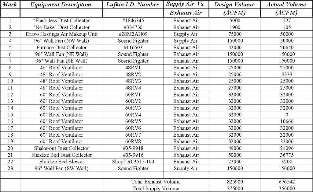
75 REV
Schust Engineering, Inc. 701 North Street P.O. Box 128 Auburn, IN (260) Fax: (260)
 Fax: (260)") Schust Engineering, Inc. 701 North Street P.O. Box 128 Auburn, IN 46706 (260) 925-6550 Fax: (260) 925-6093 Industrial Facility Midwest Re: Facility Ventilation Audit Schust Engineering, Inc. is pleased
Schust Engineering, Inc. 701 North Street P.O. Box 128 Auburn, IN 46706 (260) 925-6550 Fax: (260) 925-6093 Industrial Facility Midwest Re: Facility Ventilation Audit Schust Engineering, Inc. is pleased
ALUMINUM REPAIR CERTIFICATION EQUIPMENT. Eliminate hazardous aluminum dust with a Eurovac system. BODY REPAIR CERTIFICATION EII Wet Mix Dust Collector
 ALUMINUM REPAIR CERTIFICATION EQUIPMENT Eliminate hazardous aluminum dust with a Eurovac system BODY REPAIR EQUIPMENT OPTIONS Product Description When repairing an aluminum structured vehicle, it is essential
Kice Dust Control System Design and Maintenance Basics Design, Maintenance, & Operation
 Kice Dust Control System Design and Maintenance Basics Design, Maintenance, & Operation Kurt Meyers September 18, 2014 Topics of Discussion Why and Where do we need Dust Control? System Design Objectives
Ventilation System Description. September 8, 2000 HETA
 September 8, 2000 HETA 99-0250 Harry Enoch, Ph.D. Director, Environmental Health and Safety University of Kentucky 252 East Maxwell Street Lexington, KY 40506-0314 Dear Dr. Enoch: On June 7, 1999, the
DUST COLLECTION TRAINING. Revision 2013
 DUST COLLECTION TRAINING Revision 2013 TOPICS 1. Why does a school need a dust collector? 2. What is a dust collection system? 3. What are the maintenance requirements? 4. What are the hazards? WHY NFPA
C&W specializes in dust control for a variety of sand-related applications.
 Dust Control for Sand Operations C&W specializes in dust control for a variety of sand-related applications. We have expertise in various sand applications ranging from sand blasting, drying, classifying,
MCB SERIES. cross ventilation cartridge dust collector
 MCB SERIES cross ventilation cartridge dust collector MCB SERIES THE MOST efficient, quiet AND cost-effective SYSTEM FOR cleaner factory air. When it comes to superior dust collection, there s no better
Air Pollution Control Equipment & Service Needs
 Single Source for Your Air Pollution Control Equipment & Service Needs Benefit From Our Decades of APC Engineering & Design Solutions Contact Us to Put Our Dust Collector Engineering, Design & Installation
CLEARING THE AIR by Jeremiah Wann, president and
 CLEARING THE AIR by Jeremiah Wann, president and When fabricators CEO, Imperial Systems Inc. understand the ins and outs of downdraft table dust collection systems, employee health and safety improve For
P23 MELT CONFINED SPACE LOG
 SPACE DESCRIPTION DESIGNATION ACCEPTABLE ENTRY PROCEDURES #10004758 NON PERMIT #1 BELT PIT Conveyors with moving parts, pulleys, gears & rollers Conveyors are guarded. If guards are removed, lockout of
Introduction Airflow and filtration area General design practices Cleaning system
 FACING THE CHALLENGE JOHN RENNOCKL, CLARCOR INDUSTRIAL AIR, USA, PROVIDES HELPFUL HINTS FOR THE DESIGN EVALUATION AND OPERATION OF COAL MILL DUST COLLECTORS. Introduction Today s regulatory climate has
2How does a vibratory fluid-bed dryer work?
 As appeared in April 2011 PBE Copyright CSC Publishing www.powderbulk.com Answers to five common questions about vibratory fluid-bed dryers Doug Schieber Carrier Vibrating Equipment A vibratory fluid-bed
Now Selling FORMER B&W FOUNDRY BARBERTON, OHIO INSPECTION BY APPOINTMENT MAJOR ITEMS INCLUDE
 Now Selling FORMER B&W FOUNDRY BARBERTON, OHIO INSPECTION BY APPOINTMENT MAJOR ITEMS INCLUDE NEW 2014 TINKER OMEGA 1500 # MOBILE MIXER, NEW 2008 CAR BOTTOM HEAT TREAT, 2 8 ARC FURNACES, 6 PANGBORN TABLAST,
Pulse Jet Baghouse ASTEC PULSE JET BAGHOUSE. for Asphalt Facilities
 Pulse Jet ASTEC PULSE JET BAGHOUSE for Asphalt Facilities ASTEC PULSE JET BAGHOUSE FOR ASPHALT MIXING PLANTS Astec baghouses deliver superior performance and efficiency, while helping your plant meet
WATER WASH BOOTHS PUMP TYPE PUMPLESS TYPE
 WATER WASH BOOTHS PUMP TYPE PUMPLESS TYPE Highest Quality Finish and Environmentally Safe The Spray Systems Water wash Spray Booth provides an extremely efficient means for removing paint particles from
Dust Collectors. Unique Design & Engineering Approaches for Dust Collection and Pneumatic Conveying
 Dust Collectors Unique Design & Engineering Approaches for Dust Collection and Pneumatic Conveying AIR CLEANING EQUIPMENT, INC. (800) 962-0650 www.aircleaningequipment.com CAMCORP Inc. Established in 1993,
PDH & Professional Training
 510 N. Crosslane Rd. Monroe, Georgia 30656 (770) 266-6915 fax (678) 643-1758 PDH & Professional Training PDH Storm, by Engineers Edge, LLC CONTENTS 1. INTRODUCTION 1.1 GENERAL CRITERIA 1.2 DESIGN PROCEDURE
Traditionally, two design approaches have been commonly used for dust collection in float glass plants:
 Cullet Return Systems: Reducing costs of dust collection with efficiency A solution to eliminate wasted time for dust collection in float glass works is presented here the Dalamatic DLMV from Donaldson
Discover the Difference
 Discover the Difference In virtually every application, Scientific Dust Collectors are sized to operate at air-to-cloth ratios significantly higher than those required by less sophisticated dust collectors.
Coal Handling and Processing. Advanced Solutions for Coal-Related Environmental Dust Control. Better Air is Our Business
 Coal Handling and Processing Advanced Solutions for Coal-Related Environmental Dust Control Better Air is Our Business Coal Handling and Processing Industry Leader Our Qualifications For more than 85 years,
DALAMATIC DUST COLLECTORS
 DALAMATIC DUST COLLECTORS Proven Performance and compact Design Dust Collectors for almost any Industry and Application The versatile Dalamatic series of dust collectors deliver a powerful solution for
Combustible Dust Issues
 Combustible Dust Issues Dust Collector Requirements J Kirt Boston IAF Programs Manager Donaldson Company, Inc. Combustible Dust Impact on Collectors Rules or Requirements Discussed by Customers What areas
Product Selection Guide
 Uni-Wash, Inc. The Industrial Ventilation Group Seving Industry Since 1974 1.800.610.6010 www.uniwashinc.com Product Selection Guide DUST COLLECTION AND VENTILATION EQUIPMENT Manufactured under ISO 9001
venting method will work for all pressure conveying systems, analyzing your available equipment, your material s characteristics, and your conveying c
 Six practical ways to handle rotary leakage Jonathan O. Thorn MAC Equipment Because of the way a rotary is designed, it s normal for a small amount of conveying to leak back through the as it s bulk solid
Improving Air Emission Profiles Using Baghouses and Other Processes EVRAZ INC NA Canada Environmental Affairs Department
 Improving Air Emission Profiles Using Baghouses and Other Processes EVRAZ INC NA Canada Environmental Affairs Department Prepared by: Robert Schutzman Director of Environmental Affairs & Samantha French
High Plume Blowers Suggested Specification Section (Master Format 1996) Suggested Specification Section (Master Format 2004)
 Suggested Specification Section (Master Format 2004)") High Plume Blowers Suggested Specification Section 15500 (Master Format 1996) Suggested Specification Section 23 38 16 (Master Format 2004) PART 1 GENERAL 1.01 WORK INCLUDED High Plume Laboratory Exhaust
High Plume Blowers Suggested Specification Section 15500 (Master Format 1996) Suggested Specification Section 23 38 16 (Master Format 2004) PART 1 GENERAL 1.01 WORK INCLUDED High Plume Laboratory Exhaust
Laboratory Fume Cupboards
 Laboratory Fume Cupboards 2006 (d)irene/ /Fumecupboards 4Jun07.doc.doc The University of Hong Kong Safety Office Laboratory Fume Cupboards Table of Content 1. Introduction 2. Components of a Fume Extraction
BHA Powerwave Acoustic Cleaning Systems Powerful cleaning to help increase performance
 BHA Powerwave Acoustic Cleaning Systems Powerful cleaning to help increase performance BHA Powerwave acoustic cleaning systems can significantly improve the cleaning process for air pollution control equipment
POWDER GUIDE. Trouble shooting tips to maximise the benefits of Apcoshield Powder Coatings
 POWDER GUIDE From ASIAN PAINTS (I) LTD Trouble shooting tips to maximise the benefits of Apcoshield Powder Coatings Section A : Powder Application Problems Trouble Possible Causes Solutions 1. Poor charging
Reducing the Cost and Risk of Dust Collection in Coal
 Reducing the Cost and Risk of Dust Collection in Coal Daniel Marshall, Martin Engineering 1 Martin Place, Neponset, IL, 61345, 1800-455-2947 ex 401 danielm@martin-eng.com Table of Contents 1. Background
Indirect Gas-Fired Make-Up Air
 Indirect Gas-Fired Make-Up Air Model IG 800 to 7,000 cfm Up to 400,000 Btu/hr Multiple Furnace Control Options Optional Evaporative Cooling May 20041 Product Features Model IG Indirect Gas-Fired Make-Up
Dust Collection Tips to Keep Free-From Foods Safe from Cross-Contamination
 WHITE PAPER Dust Collection Tips to Keep Free-From Foods Safe from Cross-Contamination Cross-contamination is a serious concern in the food processing industry, especially for manufacturers that process
HIGH VACUUM - WET MIX DUST COLLECTOR
 EUROVAC HIGH VACUUM - WET MIX DUST COLLECTOR Eliminate hazardous dust and fumes with a Eurovac system How the unit works: Contaminated air is drawn into the unit through a tapered scrubber and forced down
MCB SERIES. cross ventilation cartridge dust collector
 MCB SERIES cross ventilation cartridge dust collector MCB Series THE MOST efficient, quiet AND cost-effective SYSTEM FOR cleaner factory air. When it comes to superior dust collection, there s no better
DESCRIPTION OF TECHNOLOGY
 March 2009 Underfloor Air Distribution INTRODUCTION Copyright 2009 Glumac. All rights reserved. While this Green Paper discusses primarily the use of raised access floors for air distribution, HVAC integration
XPert Balance and Bulk Powder Enclosures
 XPert Balance and Bulk Powder Enclosures Labconco Product Diversity Glove Boxes Fume Hoods Biological Safety Cabinets Freeze Dryers Glassware Washers Filtered Enclosures Carts & Mobile Benches Centrifugal
TOWER DRYERS TOTA TOT L VA AL V LUE. TOTA ALUE. TOT L SYSTEMS. AL SYSTEMS.
 TOWER DRYERS TOTAL VALUE. TOTAL SYSTEMS. 1 GSI FEATURES 1 Gravity inlet does not require leveling auger, reducing the number of moving parts. 2 3 2 Self cleaning cushion box on plenum roof reduces grain
First Revision No. 15-NFPA [ Chapter 2 ]
![First Revision No. 15-NFPA [ Chapter 2 ]](/thumbs/76/73953013.jpg "First Revision No. 15-NFPA [ Chapter 2 ]") Page 1 of 28 First Revision No. 15-NFPA 91-2013 [ Chapter 2 ] Chapter 2 Referenced Publications 2.1 General. The documents or portions thereof listed in this chapter are referenced within this standard
Page 1 of 28 First Revision No. 15-NFPA 91-2013 [ Chapter 2 ] Chapter 2 Referenced Publications 2.1 General. The documents or portions thereof listed in this chapter are referenced within this standard
FT1000 ENERGY RECOVERY WITH BLOWER DRYER FLIGHT-TYPE DISHWASHER
 701 S Ridge Avenue, Troy, OH 45374 Item # Quantity WITH BLOWER DRYER FLIGHT-TYPE DISHER C.S.I. Section 11400 STANDARD FEATURES Pumped rinse system (pressure gauge not required) Water usage 58 gph Digital
WELD STRONG BREATHE FREE
 WELD STRONG BREATHE FREE REVISED 03/01/2017 FUME EXTRACTORS THAT WORK AS HARD AS YOU DO Welding and metal fabricating can be tough, dirty jobs. But they should never be unsafe. Protecting workers from
ANNEXURE-A SPECIFICATIONS FOR HOT MIX PLANT
 ANNEXURE-A SPECIFICATIONS FOR HOT MIX PLANT COLD AGGREGATE BIN FEEDER FEEDING HOPPERS Four Nos. Cold aggregates hopper with a heaped capacity of approx. 52 T. Wide opening bin width to accommodate different
Basic Hood Considerations The design process for a successful kitchen ventilation system starts when the engineering design HVAC team receives
 Design Considerations for Commercial Kitchen Ventilation By John A. Clark, P.E., Member ASHRAE Commercial kitchen ventilation (CKV) design must consider everything needed to be coordinated to form a system
COMPETITIVE INITIATIVE POWDER COATING SPRAY SYSTEM MINES TECHNICAL SPECIFICATION
 COMPETITIVE INITIATIVE POWDER COATING SPRAY SYSTEM MINES TECHNICAL SPECIFICATION The powder coating spray system is designed for the surface preparation and painting of mines of various configurations,
Fume Hood Safety TYPES OF FUME HOODS
 Fume Hood Safety Fume hoods exhaust toxic, flammable, noxious, or hazardous fumes and vapors by capturing, diluting, and removing these materials. Fume hoods also provide physical protection against fire,
Brown University Revised August 3, 2012 Facilities Design & Construction Standards SECTION AIR HANDLING UNITS
 SECTION 23 70 00 AIR HANDLING UNITS PART 1. GENERAL 1.1 Section includes air-handling units to 15,000 cfm and accessories. 1.2 Related Sections 1 : A. Division 01 - Brown University Standard for Narragansett
REQUIREMENTS FOR HOOD PLANS
 DEPARTMENT OF PUBLIC HEALTH Division of Environmental Health REQUIREMENTS FOR HOOD PLANS Submit one (1) set of plans drawn to scale of at least ¼-inch per foot. Plans shall conform to applicable California
Objectives. NFPA Dust Specific Documents. Combustible Dust Process Hazard Safety Overview of NFPA Standards for Combustible Dusts
 Combustible Dust Process Hazard Safety Overview of NFPA Standards for Combustible Dusts Guy R. Colonna, PE Division Manager, NFPA Combustible Dust Symposium Detroit, MI September 20, 2011 1 Objectives
Displacement Ventilation
 Displacement Ventilation Displacement Ventilation Displacement Ventilation vs. Dilution Ventilation Characteristics Design Considerations Layout and Selection Product Overview Casino Case Study Dilution
Progressive Safety Services LLC 1
 Progressive Safety Services LLC 1 Progressive Safety Services LLC 2 Late 1970 s a series of devastating grain elevator explosions left 59 people dead and 49 injured. In 1987 OSHA published the Grain Handling
Selecting Fans and Determining Airflow for Grain Drying and Storage
 Proceedings of the Integrated Crop Management Conference Proceedings of the 1993 Integrated Crop Management Conference Dec 2nd, 12:00 AM Selecting Fans and Determining Airflow for Grain Drying and Storage
Biological Safety Cabinets or Fume Hoods Which one to use?
 Biological Safety Cabinets or Fume Hoods Which one to use? Betty Kupskay, MSc, RBP Biosafety Officer Department of Environmental Health and Safety University of Minnesota Minneapolis, MN kupsk001@umn.edu
Design Considerations for Abrasive Blast Rooms & Recovery Systems
 Clemco Industries Corp. presents Design Considerations for Abrasive Blast Rooms & Recovery Systems by Bob Kerr Business Development Manager Report Documentation Page Form Approved OMB No. 0704-0188 Public
Biosolids Processing Report City of Buffalo, Minnesota
 April 2017 Biosolids Processing Report City of Buffalo, Minnesota W13.112989 Submitted by: Bolton & Menk, Inc. 2040 Highway 12 East Willmar, MN 56201 P: 320-231-3956 F: 320-231-9710 Certification Biosolids
Appendix A.4.1. Safe Fume Hood User Guide
 Appendix A.4.1. Safe Fume Hood User Guide Fume hoods are devices designed for work with toxic or hazardous chemicals with the effect of safely capturing the harmful gases, vapors, and fumes generated and
The Emergence of Triboelectric Technology
 September 1998 September 1998, Pollution Engineering The Emergence of Triboelectric Technology Triboelectric monitoring, now accepted by the U.S. Environmental Protection Agency, provides continuous monitoring
FT1000 FLIGHT-TYPE DISHWASHER
 Item # Quantity C.S.I. Section 11400 FLIGHT-TYPE DISHER STANDARD FEATURES Pumped rinse system (pressure gauge not required) Water usage 58 gph Digital controls with machine diagnostics Low temperature
FT1000 ENERGY RECOVERY WITH BLOWER DRYER FLIGHT-TYPE DISHWASHER
 701 S Ridge Avenue, Troy, OH 45374 Item # Quantity WITH BLOWER DRYER FLIGHT-TYPE DISHER C.S.I. Section 11400 STANDARD FEATURES Pumped rinse system (pressure gauge not required) Water usage 58 gph Digital
Direct Fired Heater Model AD Specification
 Direct Fired Heater Model AD Specification Description A Direct-fired gas heating and ventilating unit(s), as indicated on the drawings shall be furnished. Unit(s) shall be tested in accordance with ANSI
Industrial Ventilation: It s not just Blowing Smoke! Eric Anderson, M.S., P.E.
 Industrial Ventilation: It s not just Blowing Smoke! Eric Anderson, M.S., P.E. http://www.eandersonventilation.com InDUSTrial Ventilation It could be called this Abstract Abstract: People have needed smoke
Internal ridged board 1" x 1.5 foil face installation shall be installed on roof, walls and base of casing.
 A-D WITH MPU SPECIFICATION WRITTEN SPECIFICATION Description A Modular Packaged Heating, Cooling and ventilating unit(s), as indicated on the drawings shall be furnished. Direct Fired Gas Unit(s) shall
General Design Practices in Reducing Risk in Grain Handling Facilities
 General Design Practices in Reducing Risk in Grain Handling Facilities 1 2 Facility Risks Welding Bearing failure Tramp metal Head pulley slippage Static electricity Electrical arcs Slippage in belt drives
Models SCA and SCB. ceiling-mount cartridge dust collectors. Model SCA. Model SCB
 Models SCA and SCB Model SCB Model SCA ceiling-mount cartridge dust collectors MODELS SCA AND SCB Industrial Dust Collectors for Ambient Air and Contaminants directly at the Source. INNOVATIVE ANSWER Need
Type N RotoClone. Hydrostatic Precipitator. Better Air is Our Business
 Type N RotoClone Hydrostatic Precipitator Better Air is Our Business Type N RotoClone High Efficiency Wet Collector The Type N RotoClone is the best solution to many dust collection needs. Combining high
2015 MECHANICAL CODE REQUIREMENTS
 2015 MECHANICAL CODE REQUIREMENTS ANTRIM COUNTY BUILDING DEPARTMENT PO BOX 188 205 CAYUGA STREET BELLAIRE, MI 49615 (231) 533-8373 FAX (231) 533-6041 Mechanical requirements for residential buildings per
Combustible Dust Hazard Recognition and Control NFPA Standards for Combustible Dusts
 Combustible Dust Hazard Recognition and Control NFPA Standards for Combustible Dusts Guy R. Colonna, PE Division Manager, NFPA Pellet Fuels Institute Conference Asheville, NC July 20, 2010 1 Objectives
CENTRIFUGAL BLOWERS & FANS TM MITTAL ENGINEERING
 CENTRIFUGAL BLOWERS & FANS TM MITTAL ENGINEERING TM MITTAL ENGINEERING M i t t a l E n g i n e e r i n g i s o n e o f t h e l e a d i n g m a n u f a c t u r e r s q u a l i t y e n g i n e e r i n g
2012 INTERNATIONAL FUEL GAS CODE VENTS
 2012 INTERNATIONAL FUEL GAS CODE SECTION 502 (IFGC) VENTS 502.1 General. All vents, except as provided in Section 503.7, shall be listed and labeled. Type B and BW vents shall be tested in accordance with
Explosion Prevention & Suppression James Maness JEM Safety Consulting Rehoboth, DE.
 Explosion Prevention & Suppression James Maness JEM Safety Consulting Rehoboth, DE. NGFA / Grain Journal Joint Safety / Health and Grain Quality Conference Kansas City, KS August 1, 2012 Explosion prevention
NFPA 33 Standard for Spray Applica4on Using Flammable or Combus4ble Materials
 NFPA 33 Standard for Spray Applica4on Using Flammable or Combus4ble Materials Fire Preven4on Officers Associa4on of Bri4sh Columbia 2013 Annual Seminar Kelowna, Bri4sh Columbia May 9, 2013 NFPA 33 Scope
Duct Design and Installation
 Duct Design and Installation John Proctor, P.E. Proctor Engineering Group, Ltd. San Rafael, CA 2004 Proctor Engineering Group, Ltd. 1-888-455-5742 mail@proctoreng.com www.proctoreng.com Duct Design ACCA
ELECTRO STATIC PRECIPITATOR [ESP]
![ELECTRO STATIC PRECIPITATOR [ESP]](/thumbs/74/70995864.jpg "ELECTRO STATIC PRECIPITATOR [ESP]") ELECTRO STATIC PRECIPITATOR [ESP] Fußzeilentext 1 Controlling Air Pollution Clean Air is an essential resource to the people surrounding the industrial belts. Air pollution is one of the major contributor
ELECTRO STATIC PRECIPITATOR [ESP] Fußzeilentext 1 Controlling Air Pollution Clean Air is an essential resource to the people surrounding the industrial belts. Air pollution is one of the major contributor
IBIS INTERNATIONAL, INC. DESIGN STANDARDS FOR DUCTING OF EQUIPMENT
 IBIS INTERNATIONAL, INC. DESIGN STANDARDS FOR DUCTING OF EQUIPMENT INTRODUCTION This bulletin will assist in the design and modification of ducting used to connect IBIS equipment to machinery or areas
A. Codes and Standards that are Standard at the University:
 PART 1: GENERAL 1.01 Purpose: 1.02 References: 1.03 Requirements: A. This standard is intended to provide useful information to the Professional Service Provider (PSP) to establish a basis of design. The
Land Use and Environmental Service Agency (Code Enforcement) NC Mechanical Code. Table of Contents
 NC Mechanical Code. Table of Contents") Table of Contents Chapter 1 Administration Chapter 2 Definitions Chapter 3 General Regulations Chapter 4 Ventilation. Chapter 5 Exhaust Systems Chapter 6 Duct Systems Chapter 7 Combustion Air Chapter 8
Table of Contents Chapter 1 Administration Chapter 2 Definitions Chapter 3 General Regulations Chapter 4 Ventilation. Chapter 5 Exhaust Systems Chapter 6 Duct Systems Chapter 7 Combustion Air Chapter 8
APPLICATION PROFILE EXPLOSIONS IN CEMENT PLANTS EXPLOSIONS IN CEMENT PLANTS CEMENT PLANT EQUIPMENT WITH HIGHEST EXPLOSION POTENTIAL. Form No.
 APPLICATION PROFILE EXPLOSIONS IN CEMENT PLANTS Cement manufacturing is one of the largest mineral commodity industries in the United States, with an estimated production capacity of greater than 73 million
Equipment Layout Manual. For Cooling Towers, Evaporative Condensers & Closed Circuit Coolers
 Equipment Layout Manual For Cooling Towers, Evaporative Condensers & Closed Circuit Coolers for LIFE Equipment Layout Manual Table of Contents Introduction Introduction... 2 Induced Draft Counterflow Unit
FT1000S BASE FLIGHT-TYPE DISHWASHER
 Item # Quantity C.S.I. Section 11400 FLIGHT-TYPE DISHER STANDARD FEATURES Pumped rinse system (pressure gauge not required) Water usage 58 gph Digital controls with machine diagnostics Low temperature
Contents Chapters 4 & 5 of the 2012 Michigan Mechanical Code CHAPTER 4, MMC: VENTILATION CHAPTER 5, MMC: EXHAUST SYSTEMS
 Contents Chapters 4 & 5 of the 2012 Michigan Mechanical Code CHAPTER 4, MMC: VENTILATION CHAPTER 5, MMC: EXHAUST SYSTEMS 1 Ventilation and Exhaust 2 Seminar Introduction Seminar addresses key concepts
BLAST-IT-ALL BUMPER BLASTER
 LARRY HESS AND ASSOCIATES, INC 185 PIPER LANE / SALISBURY, NC 28147 PHONE: 1-800-535-2612 / FAX: 1-704-638-9311 WWW.BLAST-IT-ALL.COM BLAST-IT-ALL BUMPER BLASTER SUCTION BLAST CABINET NOTE: It is the responsibility
DM 45 (40-60 TPH) ASPHALT DRUM MIX PLANT - DM 50 (60-90 TPH) I TECHNICAL SPECIFICATIONS DM 60 ( TPH) COLD AGGREGATE FEEDER.
 ASPHALT DRUM MIX PLANT - DM 50 (60-90 TPH) I TECHNICAL SPECIFICATIONS DM 60 ( TPH) COLD AGGREGATE FEEDER.") DM 45 (40-60 TPH) ASPHALT DRUM MIX PLANT - DM 50 (60-90 TPH) I TECHNICAL SPECIFICATIONS DM 60 (90-120 TPH) ROAD BUILDING COLD AGGREGATE FEEDER Stationary four bin cold aggregate feeder unit is with each
DM 45 (40-60 TPH) ASPHALT DRUM MIX PLANT - DM 50 (60-90 TPH) I TECHNICAL SPECIFICATIONS DM 60 (90-120 TPH) ROAD BUILDING COLD AGGREGATE FEEDER Stationary four bin cold aggregate feeder unit is with each
ASHRAE JOURNAL ON REHEAT
 Page: 1 of 7 ASHRAE JOURNAL ON REHEAT Dan Int-Hout Chief Engineer Page: 2 of 7 Overhead Heating: A lost art. March 2007 ASHRAE Journal Article Dan Int-Hout Chief Engineer, Krueger VAV terminals provide
Series V Layout Guidelines
 VT0, VT1, VF1,VF0,VC1 & VCA Open circuit cooling towers, closed circuit cooling towers, and evaporative condensers all depend upon an adequate supply of fresh, ambient air to provide design capacity. Other
Adv. 8.4 Guidelines for Biosafety Cabinets Rev
 UNIVERSITY OF CINCINNATI Environmental University Health Services 556-4968 Health and Safety ADVISORY NO. 8.4: GUIDELINES FOR THE SELECTION, INSTALLATION AND USE OF BIOSAFETY CABINETS (INCLUDING ISSUES
ENVIRO UNIT ENGINEERING MANUAL KES SERIES
 ENVIRO UNIT ENGINEERING MANUAL KES SERIES The Cadexair INC. Enviro System (KES) and Recirculation System (KRS) have been designed and constructed specifically for a commercial kitchen exhaust. The units
In accordance with the Department of Labor and Industry s statute , Subd. 11,
 In accordance with the Department of Labor and Industry s statute 326.0981, Subd. 11, This educational offering is recognized by the Minnesota Department of Labor and Industry as satisfying 1 hours of
[1] Lecture 2 Particulate emission control by mechanical separation & wet gas scrubbing
![[1] Lecture 2 Particulate emission control by mechanical separation & wet gas scrubbing](/thumbs/89/99244801.jpg "[1] Lecture 2 Particulate emission control by mechanical separation & wet gas scrubbing") [1] Lecture 2 Particulate emission control by mechanical separation & wet gas scrubbing PARTICULATE EMISSION CONTROL BY MECHANICAL SEPARATION The basic mechanism of removing particulate matter from gas
[1] Lecture 2 Particulate emission control by mechanical separation & wet gas scrubbing PARTICULATE EMISSION CONTROL BY MECHANICAL SEPARATION The basic mechanism of removing particulate matter from gas
ProcessBarron is a leader in the design, fabrication, installation, maintenance, and repair of air, flue gas and bulk materials handling system
 Mechanical ProcessBarron is a leader in the design, fabrication, installation, maintenance, and repair of air, flue gas and bulk materials handling system equipment. From our production facilities near
DUST AND FUME COLLECTOR FOR THERMAL CUTTING AND WELDING APPLICATIONS
 QUANTUM SERIES INTEGRATED SPARK ARRESTOR. DUAL PULSE TECHNOLOGY. Combining outstanding quality with reliability, easy installation and affordable pricing DUST AND FUME COLLECTOR FOR THERMAL CUTTING AND
Dry Ice Blasting Frequently Asked Questions
 Dry Ice Blasting Frequently Asked Questions 1. What is CO2 blasting? 2. How does it remove contaminants? 3. How does this differ from how sandblasting works? 4. What happens to the dry ice once it strikes
COMBUSTIBLE DUST HAZARD MITIGATION
 COMBUSTIBLE DUST HAZARD MITIGATION February 2014 GUIDE FOR FRONT LINE SUPERVISORS AND MANAGEMENT TABLE OF CONTENTS P a g e 1 A] Combustible Dust Hazard Mitigation... 4 A.1] Why Are We Here?... 4 A.2]
PORTABLE PILOT TEST UNIT. Mike Hill Shirco Infrared Systems, Inc.
 PORTABLE PILOT TEST UNIT BY Mike Hill Shirco Infrared Systems, Inc. DESCRIPTION The SHIRCO Portable Pilot Test Unit (Figure 1) was developed in response to the U.S. EPA Hazardous Waste Management Regulations
A. General: Refer to paragraph entitled "SUBMITTAL" in Section Include the following data:
 SECTION 15860 - FANS PART 1 - GENERAL 1.01 RELATED DOCUMENT A. Basic Requirements: Provisions of Section 15010, BASIC MECHANICAL REQUIREMENTS, and Section 15030, ELECTRICAL REQUIREMENTS FOR MECHANICAL
UNIVERSITY OF ROCHESTER DESIGN STANDARDS NOVEMBER 1, 2013
 SECTION 15800 - AIR HANDLING EQUIPMENT 1.1 GENERAL A. All air handlers installed shall conform to the University of Rochester specification Guideline for Semi-Custom and Pre-Engineered Air Handling Units.
Low Profile Layout Guidelines
 Low Profile Layout Guidelines Open circuit cooling towers, closed circuit cooling towers, and evaporative condensers all depend upon an adequate supply of fresh, ambient air to provide design capacity.
Fan Selection. and Energy Savings
 Fan Selection and Energy Savings Reducing power consumption by minimizing system pressure loss and choosing the right equipment HBy BRIAN MLEZIVA Greenheck Fan Corp. Schofield, Wis. Power Consumption HVAC
DUST COLLECTORS. Collectors For: Ready Mix Trucks Central Mixer Cement & Flyash Silos Cement Weigh Batcher. Dust Collector - 4/16
 DUST COLLECTORS Collectors For: Ready Mix Trucks Central Mixer Cement & Flyash Silos Cement Weigh Batcher Dust Collector - 4/16 S.O.S. (Stephens Ozone Super-Flow) Vents for Ready Mix Trucks Easy access
MJC Mini. Cartridge Filter. Features. Principal specification and options
 Cartridge Filter The MJC Mini builds on the Nederman tradition for producing robust long lasting welded filter units. Stocked as standard sub-assemblies or complete units to meet your needs for fast delivery.
UNIVERSITY SERVICES ANNEX James Madison University Harrisonburg, Virginia State Project Code: Architect s Project Number:
 SECTION 233423 - HVAC POWER VENTILATORS PART 1 - GENERAL 1.1 RELATED DOCUMENTS A. Provisions of the Contract and of the Contract Documents apply to this Section. 1.2 PERFORMANCE REQUIREMENTS A. Operating
Computer Controller. The Bio-Burner has user regulated settings as well as built-in safety features to protect you and your burner.
 BB-100 Features 3 6 1 2 5 (1) - Computer Controller (2) - Combustion Chamber (3) - Flue Pipe (4) - Front Maintenance Covers (5) - Igniter Service Door (6) - Heat Exchanger Service Panel 4 7 10 9 12 11
AEC Sales & Support Research Equipment Phone Fax East Main Street
 Research Equipment Research Accessories and Equipment COB INCLINE CONVEYOR AND COB BIN - Incline belt conveyors are designed to transfer cobs into a cob bin for convenient disposal. Cob incline conveyor