IMCE-250 EXTRUSION LINE MACHINE
|
|
|
- Simon Parsons
- 5 years ago
- Views:
Transcription

1 IMCE-250 EXTRUSION LINE MACHINE INTERNATIONAL MACHINE CONCEPTS WELCOMES YOU TO YOUR NEW MACHINE Operation Manual: Date 2017
2 CONTENTS Chapter 1 Machine Description 1.1 Uncrating Instructions 1.2 Installation 1.3 Electrical and Sensor connections 1.4 Chapter 2 Technical Parameters and Description 2.1 Chapter 3 Operating Instruction Starting the machine for the first time 3.0 Computer screens and description 3.1 Mechanical description and adjustments 3.3 Chapter 4 Malfunctions (Faults) and their rectification Table of possible faults 4.1 Chapter 5 Maintenance instructions Chapter 6 Mechanical Drawing 6.1 Electrical Panel Layout 6.2 Sensors Drawing 6.3 Chapter 7
3 Electrical diagrams 7.1 Chapter 8 Manufacturers manuals 8.1 Servo drivers Chapter 9 Spare parts list 9.1
4 Chapter Machine Description This machine or production line is manufactured from many components and the final operation of the machine is to achieve either a bar shaped extruded product or a ball. For either of these two final products to be realized correct product has to be inserted into the first part of the line. The line is made up of the following essential sub machines. 1. The extrusion system 2. The extrusion nozzle 3. The take off /away conveyor system (no longer in system) 4. The cutter/blade system 5. The take away conveyor 6. The ball forming system 7. The take away conveyor The raw material is to be entered into the extrusion line via the hopper on top of the extrusion unit, care must be taken to ensure that the product does not clog up the extrusion transfer wheels, should this happen, the raw material is either to sticky or to tough and smaller quantities should be thrown into the extrusion to allow for easier extrusion. Should the extrusion line extrusion transfer wheels get clogged up, then the unit will need to be cleaned either by dismantling the unit and cleaning or removing the material and running some hot water through the extrusion system to alleviate the blockage. It must be understood that the extrusion system has two drive systems, The product extrusion transfer wheels and the screw extruder. Both these units can be adjusted for speed individually. The appropriate speed of these two items as well as the relative speed can only be determined when the line is running with appropriate product. This will take time and experience to determine as there is no correct setting. NOTE: Air temperature, relative humidity and fluidity of the product will determine the final extrusion settings.


5 Extrusion Transfer Wheels Extrusion Screws (Two) Note: See mechanical drawing of the system for removal and cleaning/dismantling Extrusion heads will determine the final shape of the product. If the product is pushed out of the extrusion head and the product is not consistent, i.e. It contains bubbles or space between the product. Change the speed settings of the extruder to alleviate these issues. The final product shape will be determined by the extruder nozzle. Extrusion Nozzle The extruded product will exit the nozzle and take on the same form as the nozzle internal. For bars the nozzle will be 4 sided and for the ball former the nozzle will be round. The final weight of the product will be determined by a combination of features. Bulk density of product Extruded area. Extruded cut length The take off conveyor speeds can be set so as to match the extruded product speed. Too fast and the product will be pulled apart and too slow and the product will be compressed causing a snake effect on the conveyor belt. The rope effect of the extruded product can now be passed under the cutter and the product can be cut accordingly. Correct length of the cut product can be achieved by changing the cutting frequency of the blade. This cut product length will determine the final bar length. For balls the product length must be determined so as to not jam the ball former and the ball weight will be determined from this length. The ball formed rope will be approximately equal in all dimensions prior to the ball former. Should a smaller ball be required, the following parts require changing. Extrusion nozzle Ball former plates- Male and Female

6 Ball former plates Note: Cut product of the incorrect size will not go through the ball former and will cause a blockage. The final exit conveyor can be set so as to provide the operator with a reasonable packaging experience. v Correct setting up of the machine is essential for correct operation and specific attention should be paid to the following areas. The person who operates this packaging machine must know the contents of this manual in detail. The operator and at least two mechanical and electrical staff will need to be trained on the machine after commissioning to ensure that daily maintenance of the machine. NOTE: All these areas will be covered in a later chapter (Chapter 3) Machine Safety Guides The following safety guides pertaining to this machine must be observed in order to prevent accidents with this machine: The installation of all safety devices, such as protective doors, must be closed to enable the machine to operate. Note these parts cannot be dismantled. The machine operators must check the machine for any foreign objects that could cause damage to the machine prior to switching on and operation. Once the machine is running, no hands are to be placed or inserted near the sealing area as well as any of the running parts Safety with the Operational Parts The power supply must be switched off when the machine is being cleaned or repaired. If the machine is equipped with a hopper, do not insert hands or fingers into the filling device during operation.
7 Please report any damaged safety equipment on the machine as soon as damage is noted. The entire power source must be cut off during non-production. v Please note: Mechanical and bodily harm will be caused if the following parts are tampered with during production: The area at the cam transmission mechanism. In case of emergency, press the red EMERGENCY STOP button on the machine. The machine will stop running immediately. After troubleshooting, the button can be reset The Safety Devices Emergency Shutdown Button In case of emergency, press the red EMERGENCY STOP button on the machine. The machine will stop running immediately. After troubleshooting, the button can be reset. Reset the Emergency Shutdown Button after activation by releasing with a quarter turn Safety Covers Check The state of the safety protection cover must be inspected before restarting the machine Structural Principles Structural Composition This machine is made up the following parts the electronic control system, the frame and stainless steel cover, the hopper, the extruder, the extruded dough conveyor, the cutter and the ball-making mechanism. Electrical Composition The electrical part of the machine consists of a PLC programmed by a computer programmer; a frequency converter runs this system. This is a highly integrated, well-controlled and reliable operation. The application of the touch screen technology allows for a more reliable, convenient and interactive interfacing for the operator. The Photo-electric Sensors, Encoders, proximity switches and various other switches are made up of high quality advanced sensor components, this allows for precise performance of the mechanical and electrical components.

8 Main Machine Components 1 Hopper 6 Extruder Nozzle 2 Stainless-Steel Machine Casing 7 Shute to Ball-Making Machine 3 Cutter 8 Ball-Making Machine 4 Conveyor Belt 9 Conveyor Belt from Ball-Maker 5 Servo Motor
9 1.2 Un-crating Instructions The machine is generally transported in wooden crates. During uncrating make sure that no physical damage to the outside of the crate has taken place. Carefully break open the exterior panels to reveal the machine and its working parts. The machine will be covered in a plastic protective cover. This is to be removed. Make sure that no parts have been damaged during transport, or fallen off the machine. The machine will get to you with certain parts dis-assembled. These need to be fitted to the machine to resemble the photos above of the machine. The machine is affixed to the wooden pallet by four metal brackets. Remove these brackets and discard or keep for future use. The doors and covers have been taped closed for safety reasons; these taped parts can now be opened. Surface rust can take place due to the excessive sea air during shipping. This will only be surface rust and a dry cloth should be used to remove this rust residue. The entire machine was shipped with an oil coating on the machine to safeguard the machine from corrosion. This can now be removed with a very light detergent. The non stainless steel parts should be re-oiled to prevent rusting taking place after cleaning. Do not leave the machine wet. The machine is top heavy and as such care should be taken when handling the machine and removing it from its wooden pallet. Handling After unpacking, a forklift can be used to maneuver the machine into position; the length of the fork must be long enough to reach under the width of the machine. See figure below. The center of gravity of the machine is about 1500mm from the right hand side (the electrical box side) frontal view of machine. NOTE: Do not handle the machine on the upper surface of the machine. This area has safety covers that might break. Under these covers are the upper movement systems. These parts are critically aligned and should they be bent out of position the bags may run off and the machine will not function.
10 1.3 Installation v only a qualified technician should perform the machine installation or a suitably trained person. Note: It is dangerous to work on a moving machine and the machine should be off and isolated before any form of work is performed Machine should be placed in a well- ventilated room free from dust and excessive corrosion type materials There should be at least 1.5 meters space around each side of the machine for convenient operation and maintenance. Power Requirements; three Phase, 380V, 50Hz, five-wire power supply, and to connect to an appropriate earth wire. Machine should be placed on flat ground. After installing machine, check if the machine is level by level instrument, if not, please adjust by the eight legs Check every part of the machine carefully for damage during shipping. Tighten any loose parts, screws and moving parts. All gearboxes should be checked for sufficient oil Check all electrical connections for loose wires. Make a test of the machines electrical power supply and confirm the voltage and earth continuity. All safety connections relative to your own country should be adhered too. TEST Voltage: Phase to Phase 380v AC Voltage: Phase to Neutral 220v AC Phase to Earth - >5000m Ohms Earth continuity <1 Ohm Compressed air supply >6 Bar during running conditions Before operating the machine, please lubricate the following parts: linear bearings and its bearing holes located in the rack system (Cover), cams located on horizontal main shaft. Although the machine has been designed to be virtually oil free. No two metal parts can run without some type of lubrication. The upper moving parts should be lubricated with silicon spray periodically to reduce wear.

11 1.3.1 Operation Panel Introduction Introduction to the Switches on the Operation Control Box EXTRUDER SCREW EXTRUDER ROLLER L1 QF KM TYPE AND NAME 7 OF THE MACHINE L 24V TOUCH SCREEN PANEL L N KA6 0V INDICATOR LIGHT SHOWING POWER TO MACHINE N KM UPPER PRESS KA6 MOTOR 0.75 PLC 5 - Cutting Blade 6 - Ball-Rounding Machine 7 - Second Conveyor EMERGENCY STOP BUTTON Control Panel Emergency Stop Emergency stop of the entire machine Control Panel Light - The machine is powered on. To Stop the machine: Use the touch screen Stop Button The Motor v Emergency Stop Button This will stop the machine from running immediately, this stop should only be used in an emergency condition. Make sure the rotations of the motors are correct. The motors will have the wiring wrapped around the outside of each motor. These will need to be unwound and all electrics will need to be connected properly, see Chapter..for installation instructions.
12 1.3.4 Description of the machine The machine is used for the food industry, its function as a whole is for dough extrusion, cutting and rolling into balls, ball size is as per customers request. The machine has electronic and sensor controls. The dough needs to be placed into the hopper and the machine will cut and roll the dough after extrusion. 1.4 Electrical and Sensor Connections Chapter Technical Parameters and Description Voltage Power Supply Cutting Time per Piece Machine Power Machine Size 380V 50Hz. Total power is 3KW 2-10 Seconds 3KW 4500mm x 1000mm x 1200mm * The actual working environment shall be based on the characteristics of the materials. Speeds can be compromised by material and powder characteristics.


13 Chapter 3 Operating Instructions Main Parts of the machine The frame is made up of Stainless-Steel and 70 X 50mm square tube. The frame is equipped with adjustable feet as well as wheels for easy moving and positioning. The frame is clad with Stainless steel. The machine is made up of the following parts: The Frame The Stainless Steel Machine Casing


14 The Extruder The extruder is equipped with a ripple roller, when the dough is placed into the hopper, the ripple roller will rotate and press the dough into the rotating screw which will extrude the dough onto the conveyor in a bar shape. The size of the bar will depend on the size of the nozzle attached. Dough Conveyor The bar of dough will be fed towards the cutter via the conveyor belt. The cutter is controller by the servomotor. The size of the dough cutting can be controlled by via touch screen.


15 The Blade Ball-making Mechanism The cut dough will be conveyed to the Ball-making machine. The rounded dough will then be dropped onto the conveyor. The Control Panel L N EXTRUDER SCREW EXTRUDER ROLLER L1 QF KM 24V TYPE AND NAME 7 OF THE MACHINE L TOUCH SCREEN PANEL KA6 0V INDICATOR LIGHT SHOWING POWER TO MACHINE N KM UPPER PRESS KA6 MOTOR 0.75 PLC 5 - Cutting Blade 6 - Ball-Rounding Machine 7 - Second Conveyor EMERGENCY STOP BUTTON

16 The Motors 3.0 Starting the machine for the first time It is always advisable to rotate the machine at very slow speed using the jog function to ensure that the parts as shown above operate correctly. Testing using the manual functions can be performed before automatic function is processed. Ensure that all the above installation is carried out and tested before starting the machine for the first time. Full knowledge of the touch screen system should be understood before starting the machine. v No mechanical obstruction should be noted and all lubrication should be carried out. v Electrical tests to determine correct voltage and phasing (direction) must be carried out v Pneumatic connection must be made and pressure should be correct. Proceed with caution:


17 3.4 Computer screens and description IMC Logo Screen Home Screen
18 Start- up Screen Push Button Auto Allows operator to Auto-start the machine Push Button Stop Allows operator to stop the auto start-up On/Off Screen Switch Button Home Menu swap (System Setup for Home Screen settings Screen Switch Button Parameters Menu swap (System Setup for Parameters Screen settings) Screen Switch Button Manual Menu swap (System Setup for Manual Screen settings Screen Switch Button Password Menu swap (System Setup for Password Screen settings)

19 Manual Screen Push Button Upper Roller Motor Allows operator to switch Upper Roller Motor On/Off Push Button Extruder Screw Allows operator to switch Extruder Screw Motor On/Off Push Button Cut and Convey Allows operator to switch Cut and Convey Motor On/Off Push Button Convey Before Rounding Allows operator to switch Convey Before Rounding Motor On/Off Push Button Rounding Motor Allows operator to switch Rounding Motor On/Off Push Button Convey After Rounding Allows operator to switch Convey After Rounding Motor On/Off Push Button Auto Allows operator to switch the Auto On/Off Push Button Stop Allows operator to switch the Stop Motor On/Off Screen Switch Button Alarm Menu swap (System Setup for Alarm Screen settings) Screen Switch Button Back Menu swap (System Setup for previous Screen settings)

20 Parameter Screen Display/Set Button Upper Roller Motor Set Extrusion Roller Motor Frequency Display/Set Button Extruder Screw Set Frequency for the Extruder Screw Display/Set Button Cut and Convey Set Cut and Convey Frequency Display/Set Button Convey Before Rounding Set Convey Before Rounding Frequency Display/Set Button Rounding Motor Set Rounding Motor Frequency Display/Set Button Convey After Rounding Set Convey After Rounding Frequency Display/Set Button Cut Knife Speed Set Cut Knife Speed Frequency Display/Set Button Cut Rotating Time Set Cut rotating time in seconds Display/Set Button Cut Knife Route Set Cut Knife Repetitions Screen Switch Button Back Menu Swap (Allows Operator to return to previous screen) Note: When changing parameters the system will ask you for a password the password is
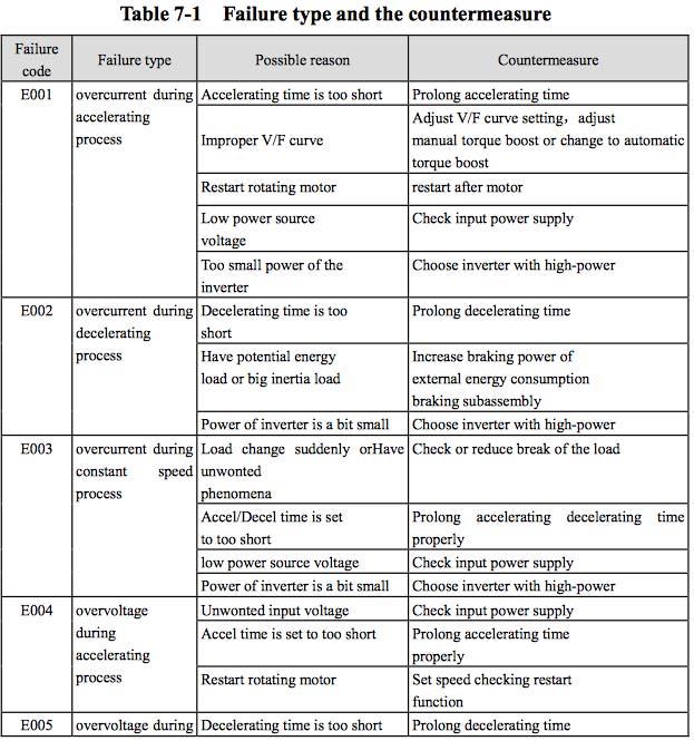
21 Alarm Screen Display/Set Button Inverter Alarm Alarm will sound if the Inverter Alarm is faulty Screen Switch Button Back Menu Swap (Allows Operator to return to previous screen)
22 3.3 Mechanical description and adjustments The Extrusion Drive Motor (2) drives the Extruder Screw (1); which pushes the product in the hopper through the Extruder Rollers and forces the product out through the Extruder Nozzle. The extruded product then is conveyed via the First Conveyor Belt (4); which is controlled by the First Conveyor Motor, to the Cutting Mechanism (5). The Cutting Blade cuts the extruded product into small chunks, the pieces are then conveyed to the Ball Making Machine (6), where each cut piece is rolled inside the Ball-making Machine into a rounded ball and dispensed onto the Second Conveyor Belt (7); which is controlled by the Second Conveyor Motor. The RV Speed Reducer drives the Extrusion Drive Motor and the Screw. The Motor Drives the Speed Reducer and the Speed Reducer Drives the Conveyor Axis via the Gear Wheel Conveyor to the Passive Axis. This then drives the power to the Ripple Roller and Screw Axis The Passive Roller Tension controls the Conveyor Length adjustment; the RV Speed Reducer drives the conveyor
 and their rectification Fault Always check the alarm screen for fault s Rectification See Alarm Screens on the drives for faults and reset Machines will not switch on Machine")
23 Chapter Malfunctions (Faults) and their rectification Fault Always check the alarm screen for fault s Rectification See Alarm Screens on the drives for faults and reset Machines will not switch on Machine is on, but the machine will not run Machine is on and main motor is running but extrusion rollers will not turn Product does not feed Check power supply to machine Check main isolator is in a reset position Check emergency stop is not pushed Have you pushed the start push button Main motor should be running, if not main motor could be faulty. Qualified personnel to check motor electrical and mechanical functionality Main motor is driven by electronic speed control system, check drive unit for fault, if in fault disconnect power from machine and wait 5 minutes and then switch on machine again. If problem persists, main drive unit may be damaged. Replace unit Check speed control knob is set to center position 5 during fault finding Check to see if the touch screen systems has been activated and are turned on Product hopper empty
24 Chapter Maintenance instructions This machine has very few moving parts and as such requires very little maintenance. Proper daily cleaning of the working surfaces needs to be carried out so that no powder residue remains on the working surfaces. Note: Not all parts of the machine are stainless steel and as such leaving these surfaces wet will result in surface rust. Daily maintenance: A visual inspection of all moving parts is to be done to determine that no parts have been damaged or corroded. Before starting the machine, any dirt or product must be removed The cutting blade needs to be inspected for damage and contamination All bearings and speed reducers need to be checked for oil. Lubricant should be changed after 3 months after start up. Oil will need to be changed every 6 months thereafter. Check that all parts are secure and inline. Monthly maintenance Lubricate all bearings in the machine Check and top up the main gearbox oil Check all electrical connections for damage or loose wiring. Please pay attention to the machine while running if there are any sound you can distinguish as abnormal. Stop and investigate Turn off the power switch when checking and cleaning the machine. Never put your hands between any of the moving parts of the machine while it is running. Pay attention when doing mechanical adjustments as this can severely influence the functioning of the machine. Check all Pneumatic and Vacuum pipes for wear and replace if necessary.
25 Check all drive belts for wear and replace if necessary Check all cams are tight and in position Check index gearbox coupling chain for slackness and tighten Check all springs for damage and re-tension if necessary Check all rod ends for looseness or wear and replace if necessary
26 Chapter Main Mechanical Equipment Drawing (Extruder) 1 Nozzle 8 Liner 2 Nozzle Connector 9 Copper Plate Bearing 3 Extrusion Roller 10 Cover Board 4 Extrusion Axis 11 Screw 5 Hopper 12 Screw Convey Axis 6 Oil Seal Ring 35 x 43 x Extrusion Slot 7 Oil Seal Ring 48 x 40 x Cover

27 Main Mechanical internal parts (Gear Box) Drawing 1 Bearing 6 Extrusion Passive Axis 2 Base 7 Extrusion Gearbox 3 Extrusion Convey Axis 8 Straight Box 4 Extrusion Cover 9 RV ,55KW 5 Extrusion Puff Cover 10 Extrusion Gear

28 Main Mechanical internal parts (Screw Conveyor) Drawing 1 Rotate Bearing Screw Cover 2 Rotate bearing Screw Cover 3 Screw Main Drive Shaft 9 Screw Cover 4 Screw Passive Axis 10 RV40 5 RV40 Base 11 Gear Wheel 6 Screw Convey

 3 4 Power Supply 5 PLC 6 Main Power Contactor 7 Circuit")
29 6.2 Electrical Panel Layout 1 Invertor Drives Extrusion Roller Invertor Extrusion Screw Invertor Extruder conveyor Invertor Ball former Invertor Ball former conveyor 2 Plc Interface relays Servo Drive (Blade) 3 4 Power Supply 5 PLC 6 Main Power Contactor 7 Circuit breaker Main Supply

30 6.3 Sensors Drawing 1 Blade Zero Position Sensor 24v Dc Inductive Sensor
31 Chapter Electrical Diagrams QF KM L N JT KA6 FWD FWD FWD FWD FWD KA1 KA2 KA3 KA4 KA5 COM U V W COM U V W COM U V W COM U V W COM U V W KM KA6 PLC CUTTING SOLENOID VALVE 3V UPPER PRESS MOTOR 3V SCREW MOTOR 3V FIRST CONVEYOR MOTOR 3V 3V BALL ROUNDING MOTOR SECOND CONVEYOR MOTOR PROJECT DESCRIPTION PROJECT NUMBER DATE IMCE-250 Extrusion Machine DRAWING NO.1 OF December 2017 DRAWING DESCRIPTION DESIGNER REVISION Electrical Drawing 1 MICHAEL MURPHY P- P+ 24 D- D+24 UVW 3V BLADE SERVO MOTOR Y0 Y1 24V L1
32 L1 QF KM L 24V N JT KA6 0V HMI 0X FWD FWD FWD FWD FWD KA1 KA2 KA3 KA4 KA5 N COM U V W COM U V W COM U V W COM U V W COM U V W KM KA6 PLC CUTTING SOLENOID VALVE 3V TOUCH SCREEN 3V SCREW MOTOR 3V BLADE - ORIGINAL POSITION FIRST CONVEYOR MOTOR 3V 3V BALL ROUNDING MOTOR SECOND CONVEYOR MOTOR PROJECT DESCRIPTION PROJECT NUMBER DATE IMCE-250 Extrusion Machine DRAWING NO.1 OF December 2017 DRAWING DESCRIPTION DESIGNER REVISION Electrical Drawing 2 MICHAEL MURPHY P- P+ 24 D- D+24 UVW BLADE SERVO MOTOR Y0 Y1 24V L1 PLC Electrical Diagram
33 L1 QF KM L 24V N JT KA6 HMI PLC XC3-24T-ELJ 0V HMI 0X FWD FWD FWD FWD FWD KA1 KA2 KA3 KA4 KA5 N GENERAL POWER SUPPLY CONTROL POWER SUPPLY KM UPPER PRESS KA6 MOTOR 0.75 PLC CUTTING SOLENOID VALVE COM SCREW MOTOR U V W V TOUCH SCREEN COM U V W FIRST CONVEYOR MOTOR V SCREW MOTOR COM BALL ROUNDING U V W MOTOR V FIRST CONVEYOR MOTOR SECOND COM CONVEYOR U V W MOTOR V BALL ROUNDING MOTOR CUTTING SOLENOID MOTOR 0.75 COM TOUCH U SCREEN V W POWER PROJECT DESCRIPTION PROJECT NUMBER DATE IMCE-250 Extrusion Machine DRAWING NO.1 OF December 2017 DRAWING DESCRIPTION DESIGNER REVISION Terminal Strip Drawing MICHAEL MURPHY P- P+ 24 D- D+24 CUTTER UVW ORIGINAL POSITION BLADE SERVO MOTOR Y0 Y1 24V L1
34 L1 QF KM L 24V N JT KA6 HMI PLC XC3-24T-ELJ 0V HMI 0X FWD FWD FWD FWD FWD KA1 KA2 KA3 KA4 KA5 N COM U V W COM U V W COM U V W COM U V W COM U V W KM KA6 PLC CUTTING SOLENOID VALVE 3V TOUCH SCREEN 3V SCREW MOTOR 3V FIRST CONVEYOR MOTOR 3V BALL ROUNDING MOTOR PROJECT DESCRIPTION PROJECT NUMBER DATE IMCE-250 Extrusion Machine DRAWING NO.1 OF December 2017 DRAWING DESCRIPTION DESIGNER REVISION Electrical Drawing 2 MICHAEL MURPHY P- P+ 24 D- D+24 UVW BLADE SERVO MOTOR Y0 Y1 24V L1

35 Chapter 8 Manufactures manuals Servo Drivers Invertor Drives EDS-A200 Series Single-phase Induction Motor Specialized Inverter n Features of EDS-A200 l Adapt to single-phase motor l 20%-50% efficiency saving l Pulse/analog input output channels; l 8 segments speed control; l Multiple running frequency/command specified channels; l Can realize copy for parameters by using long-distance keyboard; l Hi-performance isolating OC output, AC or DC load of 220V/0.5A Power range: 0.2kw~3.7kw 220V
36
37
38


39 Chapter 9 Spare Parts List Description Qty Unit Photo Recommended 1 Oil Seal Bearing 1 Pcs 35 x 43 x 10 2 Oil Seal Ring 1 Pcs 48 x 48 x 10 3 Extrusion Nozzle 1 Pcs 4 Ball-making Mechanism 1 Pcs 5 Conveyor Belt 1 Pcs


40 7 Blade Holders 1 Pcs 8 Conveyor Bearing 1 Set 9 Blade 1 Pcs 10 Conveyor Chute 1 Pcs 11 Extruder Rollers 1 Pcs


41 12 Motor 1 Pcs 13 Servo Motor 1 Set 15 Motor Gearbox 5 Pcs 16 Frequency Converter 6 Pcs 17 PLC 1 Pcs


42 18 Relay and Contactor 1 Pcs 19 Servo Drive 1 Pcs 20 Realys 1 Pcs
Technical Data. Name: ERIKA Automat fully automatic machine to divide and to round dough pieces of the same size
 AUTOMAT MANUAL 1 Technical Data Name: ERIKA Automat fully automatic machine to divide and to round dough pieces of the same size Type Divisions Dough Portions (in ounces) Plate Nos. 3 30 1.0 3.5 #35 4/40A
TLA-1245 EFFICIENT HEAT CYCLE SHRINK TUNNEL OPERATION MANUAL
 TLA-1245 EFFICIENT HEAT CYCLE SHRINK TUNNEL OPERATION MANUAL Contents 1. Introduction... 3 1.1 Features... 3 1.2 Specifications... 3 2. Installation... 3 3. Machine explosion drawing... 4 4. Equipment
INSTALLATION and OPERATION BALL WASHER MODEL NO: BW-022
 Easy Picker Golf Products, Inc. 415 Leonard Blvd. N., Lehigh Acres, FL 33971 PH: 239-368-6600 FAX: 239-369-1579 Service: 800-982-4653 SALES: 800-641-4653 www.easypicker.com salesdept@easypicker.com INSTALLATION
INSTALLATION and OPERATION BALL WASHER, HIGH CAPACITY MODEL NO: BW-022AN
 Easy Picker Golf Products, Inc. 415 LEONARD BLVD. N., LEHIGH ACRES, FL 33971 PH: 239-368-6600 FAX: 239-369-1579 Service: 800-982-4653 SALES: 800-641-4653 www.easypicker.com salesdept@easypicker.com INSTALLATION
EAGLE 2000B EAGLE 2000BE EAGLE 2000EBT MUST READ MANUAL PRIOR TO INSTALLING MACHINE
 EAGLE 2000B EAGLE 2000BE EAGLE 2000EBT MUST READ MANUAL PRIOR TO INSTALLING MACHINE Contents 1 Machine Safety Information 3 1.5 Safety Precautions Prior to Operating Machine 6 2 Machine Installation 7
CAUTION. Machine: SHRINK LABEL AUTOMATIC APLICATOR. Model: SLEEVEPRO 450AB. Input Voltage: 400 VAC, 3PH, 50Hz. Contact:
 CAUTION Read carefully all the instructions of this manual before start any operation on this machine. Do not put your hands close to any moving part of the machine. Do not make any adjustment when the
CHIPPER PC1 INSTRUCTIONS FOR INSTALLATION OPERATION AND MAINTENANCE. Series 35
 Cl/SfB (73.4) X CHIPPER PC1 INSTRUCTIONS FOR INSTALLATION OPERATION AND MAINTENANCE Series 35 Imperial Machine Company (Peelers) Limited Harvey Road, Croxley Green, Herts WD3 3AX, England Telephone: 01923
OPERATING & SERVICE PARTS MANUAL HDS-215 COMBINATION SHRINK SYSTEM
 OPERATING & SERVICE PARTS MANUAL HDS-215 COMBINATION SHRINK SYSTEM FOR HOT KNIFE AND IMPULSE MACHINES READ ALL INSTRUCTIONS CAREFULLY BEFORE OPERATING EQUIPMENT TABLE OF CONTENTS Electrical Requirements
KF-250 Knife Folding Machine
 KF-250 Knife Folding Machine Serial Number Date Page left blank intentionally 2 Table of Contents INTRODUCTION... 5 PREFACE... 5 SPECIFICATIONS... 5 ELECTRICAL SPECIFICATIONS... 6 SAFETY PROCEDURES...
INTERNATIONAL MACHIINE CONCEPTS. Operating Manual. Tablet Counting and Filling Machine. Model IMC
 Operating Manual Tablet Counting and Filling Machine Model IMC-16-1 - CONTENTS 1. Precautions 2. Introduction to the machine 3. Relevant Technical Data 4. Working environment 5. Introduction to the control
User s Manual. TIGER S EYE E-Series Mark V Jockey. TIGERFLOW Systems, Inc Mint Way Dallas, Texas
 User s Manual TIGER S EYE E-Series Mark V Jockey TIGERFLOW Systems, Inc. 4034 Mint Way Dallas, Texas 75237 214-337-8780 www.tigerflow.com TABLE OF CONTENTS Introduction... 4 Sequence of Operation... 5
OPERATION MANUAL KP4041 POLY SCRAP COMPACTOR
 OPERATION MANUAL KP4041 POLY SCRAP COMPACTOR IBIS INTERNATIONAL Thank you for purchasing the KP4041 Poly Scrap Compactor. IBIS appreciates your confidence in our product, and promises to support its operation
Shredder FD 8906CC Cross-Cut
 Shredder FD 8906CC Cross-Cut 1/2017 OPERATOR MANUAL Machine Specs Model: FD 8906CC Motor Power Sheet Capacity Serial #: 7.5KW (10HP) Three-phase, 220V, 50/60 Hz, 50 Amp dedicated line required, CS8365
DEPOSITOR (400, 450,)
") Enter Serial No. here. MANUAL No.Y-OM-03E In the event of an enquiry please quote this serial number. Store this document safely and ensure it is available at all times. Non-availability may affect the
Enter Serial No. here. MANUAL No.Y-OM-03E In the event of an enquiry please quote this serial number. Store this document safely and ensure it is available at all times. Non-availability may affect the
PS-2/ES Automated pack & tag machine with IndES fastening system
 English Manual PS-2/ES Automated pack & tag machine with IndES fastening system Contents 1. Introduction 2. Important Safety Instructions 3. PS-2/ES 4. Unpacking the machine 5. Setting up the machine 6
10 and 12 Meat Slicer MS250 & MS300 Operating Manual
 10 and 12 Meat Slicer MS250 & MS300 Operating Manual Introduction Thank you for purchasing a Pantheon Catering Equipment product. In this booklet you will find instructions for safe operation so please
CONDITIONS OF SALE AND WARRANTY
 M.E.P. Mbl 100 Monoblock - Operator s handbook CONDITIONS OF SALE AND WARRANTY 1. Read carefully this operator's handbook before operating our Mbl 100 Monoblock. 2. M.E.P. guarantees his Mbl 100 Monoblock
Operator Manual AUTOMATIC BUN DIVIDER ROUNDERS
 Operator Manual AUTOMATIC BUN DIVIDER ROUNDERS Pagina 2 CONTENT 1 - GENERAL 2 - PRODUCT INFORMATION 2.1 VOLTAGES 2.2 POSSIBLE VERSIONS 2.3 MATERIALS USED 3 - PRODUCT CONCEPTS 3.1 WARNINGS 3.2 DESCRIPTION
ASG EZ-9000GR Tape Dispenser User Manual ASG #66136
 ASG EZ-9000GR Tape Dispenser ASG #66136 Revision Date: 03/27/18 1 Read Before Use Warnings and Cautions The safety guidelines in this instruction manual must be observed in order to prevent injury to the
Product Information. Brushes. Drum brace cable
 Product Information Mega-Polisher Washing & Polishing Equipment Top cover Sliding door Infeed chute Drum drive belt Drum motor gearbox Brush motor gearbox Brush drive belt Synchronous belt Drum Brushes
C-IV 60 CEILING FAN READ AND SAVE THESE INSTRUCTIONS. FAN RATING AC 120V. 60Hz
 C-IV 60 CEILING FAN READ AND SAVE THESE INSTRUCTIONS FAN RATING AC 120V. 60Hz Please do not use any electric or battery powered tools in the assembly and installation of this or any Matthews Fan Company
IMCF- MS800 Series of FFS Machinery
 IMCF- MS800 Series of FFS Machinery INTERNATIONAL MACHINE CONCEPTS WELCOMES YOU TO YOUR NEW MACHINE Operation Manual: Date 2015. Version 2. Serial Number 1 CONTENTS Chapter 1 Machine Description 1.1 Uncrating
3500 SERIES CONVECTION STEAM COOKER PARTS AND SERVICE MANUAL
 3500 SERIES CONVECTION STEAM COOKER PARTS AND SERVICE MANUAL EFFECTIVE JULY 30, 2014 Superseding All Previous Parts Lists. The Company reserves the right to make substitution in the event that items specified
SOP: LFA SOP For Automatic Capsule Filling Machine
 SOP For Automatic Capsule Filling Machine Alastair Sanderson 31/08/16 1 Objective To provide the operating procedure for Automatic Capsule Filling Machine. 2 Scope Includes the operating procedure for
52 CEILING FAN READ AND SAVE THESE INSTRUCTIONS FAN RATING AC 120V.
 Irene 52 CEILING FAN READ AND SAVE THESE INSTRUCTIONS FAN RATING AC 120V. 60Hz TABLE OF CONTENTS Tools and Materials Required... 1 Package Contents... 1 Safety Rules... 2 Mounting Options... 3 Hanging
1. STANDARD CONTINUOUS LAMINATING MACHINE FOR THE PRODUCTION OF FLAT WALL PANELS
 Proposal and Specification for the supply of continuous Caterpillar Laminating Press to manufacture insulated Wall and DPR Roof panels from Mineral Wool and Expanded Polystyrene (EPS) and PIR/PUR (PU BLOCK)
Spiral Dough Mixer. Instruction manual. Model: CP821
 Spiral Dough Mixer Instruction manual Model: CP821 SPARE PARTS LIST OF CP821 NO. Description QTY. NO. Description QTY. 1. Small chain wheel of main shaft 1 29. Chain 06B-1-70L 2 2. Big chain wheel 3 30.
The Classeq under counter range
 Installation & Operators Manual The under counter range Part number 902.0011 Revision C Effective date January 2010 Language English Glasswashers Eco 1 Eco 2 Eco 3 Duo 2 Duo 3 Dishwasher Hydro 500 Hydro
OWNER S MANUAL ABSFBM-200T
 OWNER S MANUAL ABSFBM-200T American Baking Systems, Inc 290 Legion Court S.W. Cedar Rapids, IA 52404 Phone: 319-373-5006 Fax: 319-373-5008 CONTENTS Introduction (2) Installation & Commissioning (3) Operation
CBT LW MAINTENANCE GUIDE
 CBT LW MAINTENANCE GUIDE PICTOGRAMS Each Signifier displayed here is specific to this User Manual. Menu Previous Advance Note Tip Example Powder Feeder Mixing Bowl Weigh Scale CBP Tanks Control Panel PSD
PARTS & ACCESSORIES INSTALLATION AND SAFETY INSTRCUTIONS ITEM NO.:60010BZGTGLD SAFETY PRECAUTION. Canopy. Downrod. Housing. Transmitter CR2032/3V
 L I G H T I N G INSTALLATION AND SAFETY INSTRCUTIONS ITEM NO.:000BZGTGLD SAFETY PRECAUTION PARTS & ACCESSORIES Canopy Downrod Housing WARNING To make sure power is off before attempting installation. WARNING
XPS-ProDry User s Guide Dryer Base
 XPS-ProDry User s Guide XPS-ProDry User s Guide Dryer Base For Use with Inkjet Imaging Systems Manual Part#: M-3120 Revision: August 2005 XPS-ProDry User s Guide Written by Frank Mauri & John Brand Published
Installation Instructions
 Model: Page: ACT-3120 ACT-3340 Page 1 of 6 Installation Instructions INSTALLATION MUST BE PERFORMED BY QUALIFIED SNAP-ON/SUN PERSONNEL ONLY INSTALLATION OVERVIEW: This Installation Instructions will prepare
PELLET MILL. construction s prescriptions and safety. Besides, Nova Pellet S.r.l. has obtained in 2007 the Italian
 PELLET MILL N-MIDI pellet mill machine is projected and manufactured in accordance with CE norm about construction s prescriptions and safety. Besides, Nova Pellet S.r.l. has obtained in 2007 the Italian
FOR SERVICE TECHNICIAN ONLY DO NOT REMOVE OR DESTROY WARNING
 WARNING Electrical Shock Hazard Disconnect power before servicing. Replace all parts and panels before operating. Failure to do so can result in injury or death. IMPORTANT Electric Discharge (ESD) Sensitive
Integrated Packaging Systems, Inc.
 Integrated Packaging Systems, Inc. Tablet Filling Liquid Filling Design for your success Bottle Handling ProCount Tablet Counter/Filler The ProCount Slat Counter/Filler is our flagship tablet counter.
Best warranty!! Bale chamber bearing warranty 5 years or bales.
 AGRONIC Best warranty!! Bale chamber bearing warranty 5 years or 50 000 bales. AGRONIC, Finland's best selling integrated baler wrapper - now improved. The AGRONIC did not get its second R for nothing.
Bliss Box Former Troubleshooting. 6.1 Troubleshooting Chart. Troubleshooting INTRODUCTION SAFETY PROCEDURES
 6.0 Bliss Box Former 1.0 INTRODUCTION Table 6-1 provides a logical sequence of tests that are designed to isolate problems with the Bliss Box Former machines. This table includes a list of probable causes
MDX. Non-Cycling Refrigerated Compressed Air Dryers with zero-loss Intellidrain. Operation & Maintenance Manual MODELS MDX
 MDX Non-Cycling Refrigerated Compressed Air Dryers with zero-loss Intellidrain Operation & Maintenance Manual MODELS MDX 800 1000 1200 TABLE OF CONTENTS HOW TO USE THIS MANUAL 2 SYMBOLS 2 WARRANTY 2 1.0
UNIVERSAL SERIES COMBINATION SHREDDER-FEEDER-EXTRUDER X:GRAN.
 UNIVERSAL SERIES COMBINATION SHREDDER-FEEDER-EXTRUDER X:GRAN > ONE-STEP technology > Process bulky plastic scrap > One-button automatic On/Off control > DUMP and RUN operation www.ngr.at TECHNOLOGY THE
User Manual for ICB Meat Grinders Models HM-12, HM-22B
 User Manual for ICB Meat Grinders Models HM-12, HM-22B INTRODUCTION This manual provides information about the appliance and the manufacturing standards applied, as well as all instructions for use and
XC-18. NOTE: *Machine shown without Lift-Up Safety Guard. This guard is included with machine. Machine should not be operated without this guard.
 XC-18 NOTE: *Machine shown without Lift-Up Safety Guard. This guard is included with machine. Machine should not be operated without this guard. EXTREMA MACHINERY COMPANY, INC. PO BOX 1450, ALBANY, LOUISIANA
Los Angeles Abrasion Machine HM-70A & HM-70AF
 Operating Manual Los Angeles Abrasion Machine HM-70A & HM-70AF Rev: 07/24/2018 PHONE: 800-444-1508 740-548-7298 P.O. Box 200, Lewis Center, Ohio 43035-0200 E-mail: customerservice@gilsonco.com Website:
EN l Senking Batch Transfer Drying Tumbler DT Senking Batch Transfer Drying Tumbler DT High performance with less energy
 EN l Senking Batch Transfer Drying Tumbler DT 60 240 Senking Batch Transfer Drying Tumbler DT 60 240 High performance with less energy Single dryer with loading belt. directly side by side. The dryers
GL190-A / GL191-A / GJ461-A
 Planetary Mixer Instruction manual Model: GL190-A / GL191-A / GJ461-A GL190-A_GL191_A_GJ461-A_A5_v3_170809.indb 1 2017/8/9 17:39 Exploded diagram and spare parts list GL190-A GL190-A_GL191_A_GJ461-A_A5_v3_170809.indb
UNiVERSAl SERiES SHREDDER-FEEDER-EXTRUDER COmBiNATiON A:GRAN.
 UNiVERSAl SERiES SHREDDER-FEEDER-EXTRUDER COmBiNATiON A:GRAN > ONE-STEP technology > Process bulky plastic scrap > One-button automatic On/Off control > DUmP and RUN operation www.ngr.at TECHNOlOGY THE
Tornado Operations & Maintenance Manual
 TORNADO INDUSTRIES 7401 W. LAWRENCE AVENUE CHICAGO, IL 60706 (708) 867-5100 FAX (708) 867-6968 www.tornadovac.com Tornado Operations & Maintenance Manual MODEL NO. 99690 BD 22/14, 99720 BD 26/14 L9722
H uline.com 80" AUTOMATIC STRETCH WRAP DISPENSER FILM DELIVERY SYSTEM MACHINE DIMENSIONS ELECTRICAL SPECIFICATIONS
 H-1020 1-800-295-5510 uline.com 80" AUTOMATIC STRETCH WRAP DISPENSER System specifications MACHINE DIMENSIONS Length 98" Width 60" Height 91" Turntable Diameter 60" Turntable Height from Floor 3" Wrapping
RTP9 ROTARY TABLET PRESS USER MANUAL
 RTP9 ROTARY TABLET PRESS USER MANUAL LFA Tablet Presses is a trading name of LFA Machines Oxford LTD All of the content in this document is covered by copyright CONTENTS Page 1. Introduction Page 1. Technical
Model SFP-M50 Pizza Dough Moulder Operation and Service Manual
 Model SFP-M50 Pizza Dough Moulder Operation and Service Manual LBC Bakery Equipment, Inc. 6026 31 st Ave NE Tulalip, WA 98271 USA Phone: 888-RACKOVN (888-722-5686) Fax: 425-642-8310 Email: parts@lbcbakery.com
MODELS: TJ45 TJ90 Operator s Manual
 ICE DISPENSER MODELS: TJ45 TJ90 Operator s Manual Part No. 90614 Revision: H Revision Date: May 26, 2014 THIS DOCUMENT CONTAINS IMPORTANT INFORMATION This Manual must be read and understood before installing
PUGMILL/MIXER. Instruction Manual NVS-07
 92895B PUGMILL/MIXER Instruction Manual NVS-07 Attention After carefully reading this manual, be sure to store it in a safe and convenient place for easy reference. Before using this unit, please read
GREASE INTERCEPTORS. Z1192 GREASE RECOVERY APPLIANCE (GRA) INSTALLATION and OPERATION INSTRUCTIONS
 INSTALLATION and OPERATION INSTRUCTIONS") Z1192 GREASE RECOVERY APPLIANCE (GRA) INSTALLATION and OPERATION INSTRUCTIONS Note: Zurn Grease Interceptors with grease recognizing sensors are efficient appliances designed to separate grease from water.
Z1192 GREASE RECOVERY APPLIANCE (GRA) INSTALLATION and OPERATION INSTRUCTIONS Note: Zurn Grease Interceptors with grease recognizing sensors are efficient appliances designed to separate grease from water.
Bottle Height Adjustment Bottle Diameter Adjustment Cork Length Adjustment Cork Depth Adjustment
 P55 Champagne Corker Setup and Maintenance Read this carefully before operating the corker. One person should be assigned to maintain the corker. Only this primary operator should make adjustments to the
FD Heavy Duty Feeder for FD 280 Tabbing System
 FD 280-10 Heavy Duty Feeder for FD 280 Tabbing System Operator Manual 8/2011 First Edition TABLE OF CONTENTS 1. INTRODUCTION... 1 1.1 Feeder Description... 1 1.2 Items Included... 1 1.3 Operating Manual
OPERATING AND SETTING MANUAL
 COMPLETE SOLUTIONS FOR ON-DEMAND CD AND DVD PRODUCTION Speed Wrap Case Wrapper for CD or DVD Cases OPERATING AND SETTING MANUAL TP 000 156-1 - Thank you for purchasing a JMV Robotique Speed Wrap OPERATING
V-VTP Maintenance Manual
 V-VTP Maintenance Manual PO Box 501 Denver, NC 28037 ph: 704-483-9316 / fx: 704-483-4538 sales@leonardautomatics.com - http://leonardautomatics.com Maintenance Guide Proper maintenance of the tunnel finisher
Part 3 Troubleshooting
 Part Troubleshooting What is in this part? This part contains the following chapters: Chapter See page Troubleshooting 2 Error Codes: Hydro-box 7 Error Codes: Outdoor Units Error Codes: System Malfunctions
HEDMAN The HEDMAN Company 189 Gordon St. Elk Grove Village, IL
 HEDMAN The HEDMAN Company 189 Gordon St. Elk Grove Village, IL 60007 800-872-2788 NOTICE Proprietary Information - this material is not to be reproduced by any means or disclosed in any way without prior
General Characteristics.3. S.M.A.R.T System Set-up...5. Start-up Procedures.6. Shut-down Procedures 8. General Maintenance..8
 1-800-661-3842 1 TABLE OF CONTENTS General Characteristics.3 How the S.M.A.R.T System Works..3 S.M.A.R.T Technical Specifications..3 Erecting the S.M.A.R.T System..4 S.M.A.R.T System Set-up...5 Start-up
OTO BONDER OWNER S MANUAL WITH CIRCULATING SYSTEM MACHINERY DIVISION - - L to R Unit Shown
 GBAC RROTO OTO BONDER BONDER WITH CIRCULATING SYSTEM G B MACHINERY DIVISION OWNER S MANUAL L to R Unit Shown - - IMPORTANT FOREWORD 1) To ensure efficiency, the GBAC must be properly maintained. Carefully
Product instruction manual Easymount Wide Format Laminators
 Product instruction manual Easymount Wide Format Laminators The Easymount has been designed to be user friendly, however we strongly recommend you take a few minutes to read through this manual to ensure
Thermo 230 / 231 / 300 / 301 / Troubleshooting
 Thermo 230 / 231 / 300 / 301 / 350 5 Troubleshooting 5 Troubleshooting 5.1 General This section describes troubleshooting procedures for the heaters Thermo 230, 231, 300, 301 and 350. CAUTION Troubleshooting
COMPLETE LINE FOR NON SINTERED PTFE TAPE. 1-Mixing tumbler
 COMPLETE LINE FOR NON SINTERED PTFE TAPE 1-Mixing tumbler This machine is used for mixing powders and additives to obtain after a certain amount of time, an amalgamated product with a pasty consistency.
π H-2268 SANITAIRE UPRIGHT VACUUM SAFETY uline.com
 π H-2268 SANITAIRE UPRIGHT VACUUM 1-800-295-5510 uline.com SAFETY PAGE 1 OF 7 NOTE: When using an electrical appliance, basic precautions should always be followed, including the following: READ ALL INSTRUCTIONS
INSTRUCTION MANUAL Model: SU3022
 INSTRUCTION MANUAL Model: SU3022 GUARANTEE This product is guaranteed for 2 years from the date of original purchase. If any defect arises due to faulty materials or workmanship, the unit will, either
MDX. Non-Cycling Refrigerated Compressed Air Dryers with zero-loss Intellidrain Drain Trap. Operation & Maintenance Manual MDX MODELS 18 THRU 250
 MDX Non-Cycling Refrigerated Compressed Air Dryers with zero-loss Intellidrain Drain Trap Operation & Maintenance Manual MDX MODELS 18 THRU 250 TABLE OF CONTENTS HOW TO USE THIS MANUAL 2 SYMBOLS 2 WARRANTY
Model 5060/5070. Letter Opener Revision 3 Brush Transport
 Model 5060/5070 Letter Opener Revision 3 Brush Transport ON/OFF, Reset Envelope Guide Ramp / Envelope Model 5060, 5070 Letter Opener Introduction Variable Speed Track Cover Counter (Optional) Deflector
Full Size Canister Service Manual Riccar Models 1700 / 1800 Power Nozzles RPB-100 / RPB-220 / RPB-224 / RPB-250
 Full Size Canister Service Manual Riccar Models 1700 / 1800 Power Nozzles RPB-100 / RPB-220 / RPB-224 / RPB-250 Table of Contents I. General Full Size Canister Issues...2 A. Full Bag Indicator...2 1. General
Parts and Service Manual
 Section II Parts and Service Manual (70241A) CLARKE TECHNOLOGY Operator's Manual - MINI MAX Page -29- Frame and Front Cover Assembly Drawing 2/01 Page -30- CLARKE TECHNOLOGY Operator's Manual -MINI MAX
INSTRUCTION MANUAL FOR DUTCHESS MODEL 260 BAGEL & BUN SLICER
 INSTRUCTION MANUAL FOR DUTCHESS MODEL 260 BAGEL & BUN SLICER Table of Contents Safety Information I thru VII Uncrating Instructions 1 Introduction 2 Adjustment Instructions 3 Operating Instructions, Cleaning,
TH450A-CRB TH550A-CRB THP550-CRB/TS3000
 TH450A-CRB TH550A-CRB THP550-CRB/TS3000 INSTRUCTION MANUAL CLEAN TYPE INDUSTRIAL ROBOT SPECIFICATIONS Notice Make sure that this instruction manual is delivered to the final user of Toshiba Machine s industrial
VENCO - STANDARD PUGMILL ( NON DE-AIR )
") VENCO - STANDARD PUGMILL ( NON DE-AIR ) AVAILABLE SIZES: 75mm (3") nozzle 136m (5.3") barrel 180kg/hr (400lb/hr) production Hopper opening 115x100mm [4½x4 ] L x W x H [crated] 1.08 x 0.34 x 0.37 m [43
VENCO - STANDARD PUGMILL ( NON DE-AIR ) AVAILABLE SIZES: 75mm (3") nozzle 136m (5.3") barrel 180kg/hr (400lb/hr) production Hopper opening 115x100mm [4½x4 ] L x W x H [crated] 1.08 x 0.34 x 0.37 m [43
1 L Rotary Vacuum Evaporator Instruction Manual
 1 L Rotary Vacuum Evaporator Instruction Manual Important This manual is designed for safe and optimal performance of this unit Please read manual carefully before operating this unit Keep this manual
CEILING FAN OWNER'S MANUAL
 Style that revolves around you. CEILING FAN OWNER'S MANUAL Hover with DC motor 12/14 WARNING: Read and follow these instructions carefully and be mindful of all warnings shown throughout. GENERAL INSTALLATION
packagingconnection.com Div. of Express Worldwide, Inc.
 packagingconnection.com 770-410-3456 Div. of Express Worldwide, Inc. Operations Manual Eagle 2000 Series Stretch Wrapper Models B, BE, BHS, EB, EBT, BWS READ ALL INSTRUCTIONS CONTAINED IN THIS MANUAL PRIOR
Installation and Setup
 NFORMATION NO: 007 Self Fill Lavazza Colibri with changegiver Congratulations on choosing to drink great coffee using the unique Lavazza pod vending system. The machine is easy to use. Follow the simple
WAILEA OWNER S MANUAL
 WAILEA OWNER S MANUAL The blades in each pack are matched for equal weight to assure smooth fan operation. If more than one fan is being installed, be careful not to mix blades from different cartons.
Grafisk Maskinfabrik A/S Bregnerødvej 92, DK-3460 Birkerød, Denmark. Website: Phone:
 IR330 Inspection Rewinder with Label Dispenser & Inkjet IR330 Operation Manual Grafisk Maskinfabrik A/S Bregnerødvej 92, DK-3460 Birkerød, Denmark. Website: www.gm.dk. E-Mail: gm@gm.dk. Phone: +45 4581
Integrated Packaging Systems, Inc.
 Integrated Packaging Systems, Inc. Tablet Filling Liquid Filling Design for your success Bottle Handling Integrated Packaging Systems, Inc. IPS is a leader in design and manufacturing of packaging machinery
LUCCI AIRFUSION FRASER DC CEILING FAN
 LUCCI AIRFUSION FRASER DC CEILING FAN INSTALLATION OPERATION MAINTENANCE WARRANTY INFORMATION CAUTION READ INSTRUCTIONS CAREFULLY FOR SAFE INSTALLATION AND FAN OPERATION. V2.0-EN-Published on 03. 2018
MODULAR AUTOMATIC GRANULAR ICE FLAKER
 MODULAR AUTOMATIC GRANULAR ICE FLAKER INSTRUCTIONS AND WARNINGS 24479 rev. 03 It is strictly forbidden to reproduce this instruction manual or any part thereof. Dear Customer, Congratulations on having
Fig. 1. Bottle Height---Top of bottle MUST be at this height or slightly higher.
 P12 Corker Addendum: Setup and Maintenance Read this addendum and the MEP manual carefully before operating the corker. One person should be assigned to maintain the corker. Only this primary operator
40LM Hz INSTALLATION, START-UP AND SERVICE INSTRUCTIONS CHILLED WATER FAN COIL UNIT
 Carrier International Sdn. Bhd. Malaysia INSTALLATION, START-UP AND SERVICE INSTRUCTIONS CHILLED WATER FAN COIL UNIT 40LM 120-200 50Hz CONTENTS: Physical Data & Dimension 1-3 Safety Considerations 4 Rigging
 Boretech China Make, Pet Bottles Recycling Line Ref Id SM4325 (Details-Specification mentioned hereunder are for indicative purpose only) DESIGN DATA 1.1 Capacity - PET bottles input : 1,500 kg/h - Dry
TECHNICAL SERVICE MANUAL SCALA - SC
 TECHNICAL SERVICE MANUAL SCALA - SC MODELS: SCALA 400 - SC 400 SCALA 600 - SC 600 SCALA 1T - SC 1TN SCALA 2T - SC 2TN SCALA 3T - SC 3TN SCALA 5T - SC 5TN SCALA 10T - SC 10TN SCALA 15T - SC 15TN TABLE OF
READ AND SAVE THESE INSTRUCTIONS
 READ AND SAVE THESE INSTRUCTIONS CEILING FAN INSTALLATION AND OPERATION INSTRUCTION FAN RATING AC 120V. 60Hz UL LISTED MODEL: AC-552OD WEIGHT OF FAN: 6.82 KGS 1. TOOLS AND MATERIALS REQUIRED Philips screw
CONDITIONS OF SALE AND WARRANTY
 CONDITIONS OF SALE AND WARRANTY 1. Read carefully this operator's handbook before operating our G300 wire-hooder. 2. M.E.P. guarantees his G300 wire-hooder in case of breakages caused by faulty components
AHU INSTALLATION & OPERATION MANUAL
 AHU INSTALLATION & OPERATION MANUAL VERSION 2 AIR HANDLING UNIT MODELS: AHU 500, AHU 900, AHU 1200, AHU 1700, AHU 2000, AHU 2500, AHU3500, AHU 4500, AHU 5000, AHU 6000, AHU 7000, AHU 8000, AHU 10000, AHU
CMU701/ 705 OPERATIONS & INSTRUCTION MANUAL
 CMU701/ 705 OPERATIONS & INSTRUCTION MANUAL MANUFACTURED BY 2519 Fairmont Road Morgantown, West Virginia 26501 PHONE: (304)-983-2642 FAX: (304)-983-2643 www.imswv.com 1 TABLE OF CONTENTS: 1.) Introduction
HTD. High Temperature Non-Cycling Refrigerated Compressed Air Dryers. Operation & Maintenance Manual. MODELS HTD 21 thru HTD 100
 HTD High Temperature Non-Cycling Refrigerated Compressed Air Dryers Operation & Maintenance Manual MODELS HTD 21 thru HTD 100 - TABLE OF CONTENTS - 1.0 GENERAL 2 1.1 How to use this manual 1.2 Symbols
FD 90 / FD 95 Rotary Perforators
 FD 90 / FD 95 Rotary Perforators 11/2018 OPERATOR MANUAL SECOND EDITION TABLE OF CONTENTS SPECIFICATIONS 1 SAFETY PRECAUTIONS 1 DESCRIPTION 2 INSTALLATION AND OPERATION 3 INFEED TABLE ADJUSTMENT 3 OUTFEED
VT600. Operation & Parts Manual. XtraVac VT600 (PLC) Vacuum Tumbler
 Vacuum Tumbler") VT600 XtraVac VT600 (PLC) Vacuum Tumbler Operation & Parts Manual A Division of the Inauen Group Kansas City, MO USA Tel. 800-728-2999 Fax 816-472-1999 Sales@XtraVac.com Safe Operation Practices General
VT600 XtraVac VT600 (PLC) Vacuum Tumbler Operation & Parts Manual A Division of the Inauen Group Kansas City, MO USA Tel. 800-728-2999 Fax 816-472-1999 Sales@XtraVac.com Safe Operation Practices General
OWNER S MANUAL CAVN SERIES SELF CONTAINED RETRACTABLE NOZZLE VACUUM SEALER WITH GAS PURGE
 OWNER S MANUAL CAVN SERIES SELF CONTAINED RETRACTABLE NOZZLE VACUUM SEALER WITH GAS PURGE WHAT S IN THE PACKAGE? This Operation Manual. (1) Vacuum Sealer. (1) E-(unit size) Heating Element, inside the
Installation, Operation, and Maintenance Manual RTE14S & RTE14S-2. For the Taco Bell "Rethermalizer" Model Numbers
 Installation, Operation, and Maintenance Manual For the Taco Bell "Rethermalizer" Model Numbers RTE14S & RTE14S-2 NOTICES There are three different types of notices that you should be familiar with, a
INSTALLATION, OPERATION & MAINTENANCE MANUAL
 CENTRAL FANS COLASIT LTD Unit 12A, Palmers Road, East Moons Moat, Redditch. Worcs. B98 0RF Tel: 01527-517200 Fax: 01527-517195 Edition 04_13 INSTALLATION, OPERATION & MAINTENANCE MANUAL CIV Fan Range Valid
SSM-U Series Storage Mixers
 SSM-U Series Storage Mixers Date: Oct, 2013 Version: Ver.A (English) Contents 1. General Description... 7 1.1 Coding Principle... 8 1.2 Feature... 8 1.3 Technical Specifications... 10 1.3.1 Technical
Tornado Operations & Maintenance Manual
 TORNADO INDUSTRIES, LLC 7401 W. Lawrence Avenue Chicago, IL 60706 Ph (708) 867-5100 Fax (708) 867-6968 www.tornadovac.com Tornado Operations & Maintenance Manual MODEL NO. 99410 BR 13/1MW L9735Rev_C Tornado
TECHNICAL INFORMATION Touchtronic Clothes Dryers
 TECHNICAL INFORMATION Touchtronic Clothes Dryers Includes: T1302, T1303, T1322, T1329ci T1403 & T1405 2004 Miele This page intentionally left blank. Table of Contents GENERAL INFORMATION A. Warning and
FD 2052 AutoSeal 12/2007 OPERATOR MANUAL FOURTH EDITION
 FD 2052 AutoSeal 12/2007 OPERATOR MANUAL FOURTH EDITION TABLE OF CONTENTS DESCRIPTION 1 SPECIFICATIONS 1 UNPACKING AND SET-UP 1-2 CONTROLS 2 OPERATION 3 CUSTOM FOLDS 3-4 Measuring Fold Lengths 3 Custom