ONX908PIT-V1-S1-F1/B Modulating Digital Thermostat
|
|
|
- Shanon Lloyd
- 5 years ago
- Views:
Transcription
1
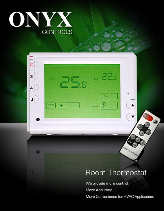
2 ONX908PIT-V1-S1-F1/B Modulating Digital Thermostat Installation and operation instructions The ONX908PIT-V1-S1-F1 modulating digital thermostats are designed to provide Proportional-Integral (PI) modulating control in 2-pipe or 4-pipe fan coil units, zoned commercial heating, Ventilating and various heating and cooling applications. This thermostat provides modulating analog 0-10V or 4-20mA control. Other available feature includes energy savings card key input, auto-detection of temperature sensor (remote sensor or internal sensor), and optional Celsius or Fahrenheit operation. SPECIFICATION: Input Voltage 24Vac, 50/60 Hz (Digital Thermostat) 24Vac-250Vac; 50/60Hz (Fan) Output Voltage Modulating output 4 to 20mA or 0-10VDC On/Off output for fan 5A 250VAC Room temperature setting range 5 to 35 (41 to 95 ) Accuracy. ±0.1 or ±0.2 Dimensions 115mm 90mm 28mm Color.. White FEATURE: Large LCD display The screen displays the set temperature, the room temperature simultaneously Permanent user setting and program setting retention during power loss, Special energy saving mode-external input from window contact or hotel card-key overrides the temperature setting to installer defined heating and cooling temperatures 0-10Vdc or 4-20mA heat and cool outputs Fan switch with on and auto Fahrenheit or Celsius display capability IMPORTANT SAFETY INFORMATION: Always turn off power at the main power source by unscrewing fuse or switching circuit breaker to the off position before installing, removing, cleaning, or servicing this thermostat. Read all of the information in this manual before installing this thermostat. Only a professional contractor should install this thermostat. All wiring must conform to local and national building and electrical codes and ordinances. Use this thermostat only as described in this manual. 1
3 KEYBOARD, DISPLAY AND SWITCH DESCRIOPTION (7) (8) (9) (1) (2) (3) (4) (5) (16) (10) (11) (6) (15) (14) (12) (13) Figure 1 Figure 2 (1) Power Button (2) System Button (3) Fan Button (4) Setback Button (5) Raise Temperature setting button (6) Lower Temperature setting button (7) Bar Graph Shows approximate Power Output of Modulation Output (8) Indicates the Portion of Modulating Output (9) Setting temperature (10) Shows temperature display in or (11) indicates when thermostat is in setback mode. (Energy saving mode) indicates when thermostat is in normal operation. (Comfort mode) (12) Indicates different fan speed (13) Shows when card key is vacant (14) Indicates system icon (15) indicates when there is a call for On/Off heating (16) Shows Current Read temperature 2
4 INSTALL THE THERMOSTAT ATTACH THERMOSTAT BASE TO WALL Screw for mounting thermostat to wall Base Control panel Figure 3 Fixing screw 1. Remove 2 screws from the bottom of thermostat. Gently pull the control panel straight off the base. Forcing or prying on the thermostat will cause damage to the unit. 2. Connect wires beneath terminal screws on power supply module using appropriate wiring schematic. See figure 4 3. Push power base into wall. 4. Using two mounting screws mount the power base to the wall. Place a level against bottom of base, adjust until level, and then tighten screws. (Leveling is for appearance only and will not affect thermostat operation.) 5. Replace control panel on the power base and fix power base and control panel by removed two screws in item 1 WIRING DIAGRAM NLOccupancy 24VAC Switch DC0~10V Or 4~20MA Modulating Output AOUT+ AGND- External Sensor Heating Relay ON OFF Med Fan Figure 4 3
5 Occupancy Switch C 24VAC R DC0~10V Or 4~20MA Modulating Output AOUT+ AGND- External Sensor Heating Relay ON OFF Med Fan Figure 5 OPERATION Control Output 1: Terminal 12 and 13. The main output of the thermostat is modulating PI analog (4~20mA or 0-10Vdc). This signal uses a variable ma signal for the control of analog damper actuator and analog valve actuator in cooling or heating. (User can select On/Off output by terminal 7 and 9 to control heating system. See configuration menu item 12) Output 2:On/off output from terminal 7 and 8. This output can be used as the main output for heating system or act as the second heating output. (See configuration menu item 12). If it is selected as the second heating output, it will activate the second stage heating when the setting temperature is 1 plus P-band value higher than room temperature. System Button Pushing system button to select among heat mode, cool mode and auto mode. Heat mode: Thermostat operates only for heating Cool mode: Thermostat operates only for cooling Auto mode: Thermostat operates in automatic change over Automatic change over function is available only when external sensor installed in terminal 3 and 4. In automatic changeover, the thermostat detects when the system switches between heat mode and cool mode by comparing the air supply temperature with the ambient temperature. If the thermostat is in heat mode, it switches to cool mode when the air supply is cooler than ambient by 5 (9 ) or more. If it is in cool mode, it switches to heat mode when the air supply is warmer than ambient by 5 (9 ) or more. Fan Button Set fan button to Med or Auto Auto is the most commonly selected setting and runs the fan only when the heating or cooling system is on. Fan runs continuously in medium speed for increased air circulation. Setback Button Holding the setback button for 5 seconds, the thermostat can shift from comfort mode to setback (energy saving). Factory default setting for setback mode in heating is 18 and for cooling is 25. Shows indicate you are now in comfort mode while shows indicate you are now in setback mode. Every time 4
6 you change the setting in comfort mode, the new setpoint will be memorized as the setpoint of the comfort mode. You can change the setback setting in configuration menu item 5 and 6 Energy Saving Mode Energy Saving mode is activated by a special input from a card key, occupancy switch or window contact switch. If the signal via input terminals 4 and 5 is calling for energy saving mode. Then the thermostat will control to user/installer defined setback setpoints for increased energy savings. The display will show symbol to indicate when this mode is active. Shows energy saving mode is activated by input signal. During energy saving mode, setpoint cannot be changed. The setback setpoint can be change in configuration item No.6 and No.7. Factory default setting for heating is 18, for cooling is 25. For example, if the user setpoint is 21 and the energy Savings Mode setpoint for cooling (unoccupied cooling setpoint) has been set to 28, then the thermostat will control to 28 when the input signal activated the Energy Saving mode.. The energy saving mode input can be configured within the configuration menu item 13 to be Card activated either a short circuit (default) or open circuit signals. 4 5 Dip Switch: A two-way DIP switch allows selection of modulating analog output between 4 to 20mA and 0~10V. Open the thermostat, you will find the JP6 in the rear board. Following figure showing you how to select 0~10V output and 4~20mA output via change the dip switch position. 0~10V 0~10V 4~20mA 4~20mA 0~10V output 4~20mA output Note: The configuration menu item 15 should match with the Dip Switch Position CONFIGURATION Configuration Menu The configuration menu allows you to set certain thermostat operating characteristics to your system or personal requirements. Switch off the thermostat. Hold button (4) for 5 seconds to enter the configuration menu. The display will show the first item in the configuration menu 1. Press button (4) to shift to the next menu item. Use to select. To exit the menu, pressing button (1) to switch off the thermostat. If no buttons are pressed within 20 seconds the thermostat will exit the menu. To revert to factory default setting, push (2) button for 3 seconds. Display will show DEF blinking 3 times and return to Menu item 1 indicates all the configuration setting has reverted to factory default setting. The configuration menu chart summarizes the configuration options. An explanation of each option as follows: 1) Select ºF or ºC Readout Changes the display readout to Centigrade or Fahrenheit as required. 2) Select temperature recalibrates Adjustment 3 LO to 3 HI You can adjust the room temperature display up to 3 higher or lower. Your thermostat was accurately 5
7 Item Press buttons Displayed(factory default) Press to select Description 1 (4) For 5 second FC ( ) / Select ºF or ºC Readout 2 (4) CL (0) Select temperature display adjustment higher or lower 3 (4) CH (35 /95 ) 18 (64 ) 35 (95 Select maximum setpoint ) 4 (4) CC (5 /41 ) 5 (41 ) 20 (68 ) Select minimum setpoint 5 (4) UC (25 /77 ) 25 (77 )-30 (90 ) Select setback point for cooling 6 (4) UH (18 /65 ) 10 (50 )- 18 (65 ) Select setback point for heating 7 (4) PH (2) 0-10 Select P-band 8 (4) LP (5) 1-10 Integral action time 9 (4) FH (100) (50-100) Maximum integral part 10 (4) FL (0) (0-50) Minimum of integral part 11 (4) bl (1) 1/2/3 Select display backlight mode 12 (4) HF (h1) h1/of/h2 Heating output type option 13 (4) En (AC) OU/AC Active temperature sensor OU:Return air temperature sensor active AC:Room temperature sensor active AU: Mix temperature sensor active 13 (4) rc (SC) SC/OC/OO Activate energy saving mode option 14 (4) U (I) U: 0 10 VAC output I: 4-20 MA output Choose the control mode between 0~10VAC output to 4~20MA output 15 Press Power Button return to close calibrated at the factory but you have the option to change the display temperature to match your previous thermostat. The current or adjusted room temperature will be displayed on the right side of the display. 3) Select maximum temperature set point This feature provides a maximum set point temperature. The default setting is 35 (95 ), It can be changed between 18 (64 ) to 35 (95 ) 4) Select minimum temperature set point. This feature provides a minimum set point temperature. The default setting is 5 (41 ), It can be changed between 5 (41 ) to 20 (68 ) 5) Select energy saving setpoint for heating This feature provides energy saving setpoint temperature for heating. The default setting is 16, It can be changed between 10 to 18 6) Select energy saving setpoint for cooling This feature allows you to set energy saving setpoint temperature for cooling. The default setting is 25, It can be changed between 25 to 30 7) Select P-band 6
8 The proportional band is the amount of change required by the ambient temperature for the output to go from 0 to 100%. It can be adjust from 0~10. Factory default setting is 2. For example if the P-band is set in 2 in the heat mode, with a 25 set point and an ambient temperature of 25, the modulating output is 0%; at 24 the output is 50%; and at 23 the output is 100%. The intergral gain implies that the longer the error between the ambient and the set point temperatures exists, the more the output will change to eliminate the error. The integral portion of the algorithm eliminates the temperature offset from the set point. Heat mode (P-band: 2 ) When the ambient temperature is below the set point the output is somewhere between 0~100% % of Output 0-10V or 4-20mA 100% 50% 0% Figure Set point Cool mode(p-band: 2 ) When the ambient temperature is above the set point the output is somewhere between 0 and 100% % of Output 0-10V or 4-20mA 100% 50% 0% Figure Set point ) Select integral action time This feature allows you to set the integral action time for the integral to run from 0 to 100%. The value required depends on the reaction time of the control loop. If the time is chosen too short, the control loop will become instable and oscillate. If the time is chosen too long, the control loop will become sluggish. 9) Select maximum integral portion This feature allows you to set the maximum modulating output. For example, if you set the maximum integral portion to 80%, the maximum modulating output will be 8V or 16.8mA. 10) Select minimum integral portion This feature allows you to set the minimum modulating output. For example, if you set the maximum 7
9 integral portion to 20%, the maximum modulating output will be 2V or 7.2mA. 11) Display backlight option Select 1 the light will be on when any button of the thermostat is touched. Select 2 the display will keep the light on continuously. Select 3 the display will keep the light off continuously Factory default is 1 12) Heating type option h1: Only proportional output for heating control is available, terminal 12 and 13 (See Figure 4) is used as 0-10V or 4-20mA modulating output to control heating or cooling OF: Only On/Off output for heating control is available. Terminal 7 and 8 (Figure 4) is the On/Off output to control heating. Terminal 12 and 13 is used as 0-10V or 4-20mA modulating output to control only cooling. h2: 2 stage heating active. Terminal 12 and 13 (See Figure 4) is used as 0-10V or 4-20mA modulating output to control 1 st stage heating. Terminal 7 and 8 (Figure 4) is the On/Off output to control 2 nd stage heating. 13) Select active temperature sensor This feature provides two active temperature sensor option. Select OU means return air temperature sensor active Select AC means room temperature sensor active Select AU means mix temperature sensor active for seasonal changeover 14) Activate energy saving mode option This feature allows you to select the way to activate the energy saving mode. Select OC to activate the energy mode by open circuit Select SC to activate the energy mode by close circuit Select 00 to cancel the energy mode 15) Shift between 0~10VAC output to 4~20MA output This feature allows you to select the way to shift the mode between 0~10VAC output to 4~20MA output. NOTE: Do not forget to change the position of the dip switch so that it can match with output option. (See dip switch in Operation Chapter) CUSTOMER ASSISTANCE After reading this guide, if you have any question about the operation of your thermostat, please contact your installer or Energy Utility company or service provider. 8
SAS803WHL-7 Thermostat for floor heating
 SAS803WHL-7 Thermostat for floor heating SAS803WHL-7 is a 7-day programmable thermostat designed for floor warming application or helping to limit floor temperature. This thermostat can conform to water
ONX908MTW-0/24V MULTI STAGE THERMOSTAT
 ONX908MTW-0/24V MULTI STAGE THERMOSTAT Application: 24VAC,2Heat/2cool Installation and operation instructions SPECIFICATION: Electrical Rating 24VAC Terminal Load 3.0 A per terminal (terminal Y1, W1, G:
Eswa DC-1. Thermostat for Floor Heating
 Eswa DC-1 Thermostat for Floor Heating The Eswa DC-1 is a thermostat which can be used for 7-day programming of floor heating systems or for limiting floor temperatures. This thermostat conforms to the
ONX908FCT-4B/220V/RC FAN COIL THERMOSTAT
 X0FCT-B/0V/RC FA COI THERMOSTAT Application: Heat/cool, speed fan, -pipe fan coil unit Installation and operation instructions SPECIFICATI: Electrical Rating 0VAC Terminal oad.0 A per terminal Set point
SAS908WHB-3-RF/B WIRELESS THERMOSTAT
 SAS908WHB-3-RF/B WIRELESS THERMOSTAT Installation and operation instructions 908WHB-3-RF/B can replace most common residential thermostat and is designed to be used with electric, gas or oil heating control
Smart Temp. Model
 Smart Temp Model 42-160 SINGLE STAGE PROGRAMMABLE THERMOSTAT 1 Heat / 1 Cool Single Stage Thermostat. 5+2 Programmable, Compatible with Gas Heat & Heat Pump System Installation and Operation Manual SPECIFICATIONS:--------------------------------------------------------------------------------
SAS6000UTK-7 UNIVERSAL THERMOSTAT
 SAS6000UTK-7 UNIVERSAL THERMOSTAT Used with Single Stage, Multi-Stage, Heat pump Installation and operation instructions SPECIFICATION: Power Supply Dual Power 24VAC (18-30VAC,50/60Hz) or Battery Powered
T6865 Series Large LCD Digital Thermostat 24 VAC 2-pipe fan coil control
 T6865 Series Large LCD Digital Thermostat 24 VAC 2-pipe fan coil control Application Data sheet T6865 digital thermostats are designed for application of 3-speed fan and modulating valves in fan coil system.
VAV Thermostat Controller Specification and Installation Instructions. Model TRO24T4XYZ1
 Model TRO24T4XYZ1 Description The TRO24T4XYZ1 is a combination controller and thermostat. The VAV Thermostat Controller is designed for simple and accurate control of any variable air volume box in a number
1F Non-programmable Electronic Digital Heat Pump Thermostat INSTALLATION AND OPERATION INSTRUCTIONS
 FAILURE TO READ AND FOLLOW ALL INSTRUCTIONS CAREFULLY BEFORE INSTALLING OR OPERATING THIS CONTROL COULD CAUSE PERSONAL INJURY AND/OR PROPERTY DAMAGE. DESCRIPTION Your new White-Rodgers Digital Thermostat
ET10 Series Stand-alone LCD Fan Coil Thermostat
 ET10 Series Stand-alone LCD Fan Coil Thermostat Features Modern Appearance Stylish Rotary dial and buttons Large LCD with backlight Separate power supply unit with high performance relay outputs Retention
ETNC24-FC-BAC-PIR-01 Owner s manual & Technician Settings
 ETNC-FC-BAC-PIR- Rev. Index Operating instructions....- Turning the thermostat and OFF Selecting temperature scale Adjusting the Set point temperature (for set point and set points configurations) Selecting
T6590 Series FAN-COIL CONTROLLER
 T6590 Series FANCOIL CONTROLLER PRODUCT DATA FEATURES APPLICATIONS The T6590 range of digital thermostats is designed to control the valves, fan and auxiliary electric heater within fancoil systems. Modern,
1F Non-Programmable Electronic Digital Multi-Stage Thermostat INSTALLATION AND OPERATION INSTRUCTIONS
 1F83-261 Non-Programmable Electronic Digital Multi-Stage Thermostat INSTALLATION AND OPERATION INSTRUCTIONS Operator: Save these instructions for future use! FAILURE TO READ AND FOLLOW ALL INSTRUCTIONS
Rooftop Thermostat Controller Specification and Installation Instructions. Model TRT2422
 ºF / º C Rooftop Thermostat Controller Model TRT2422 Description The TRT2422 is a combination controller and thermostat with a built-in scheduler, which is designed for simple and accurate control of single
SAS6000UTK-7-WIFI OPERATING INSTRUCTION
 SAS6000UTK-7-WIFI OPERATING INSTRUCTION 1 This manual apply for SAS6000UTK-7-WIFI,used with Single Stage,Multi-Stage,Heat pump and has mobile control function. SPECIFICATION Power Supply Dual Power 24VAC
T6590 Series FAN-COIL CONTROLLER FEATURES APPLICATIONS PRODUCT DATA
 T6590 Series FANCOIL CONTROLLER PRODUCT DATA FEATURES APPLICATIONS The T6590 range of digital thermostats is designed to control the valves, fan and auxiliary electric heater within fancoil systems. Modern,
INSTALLATION & USER MANUAL
 INSTALLATION & USER MANUAL HC Digital Automatic Humidistat (Y3760) CONTROLS 506808-01 3/2016 Supersedes 6/2011 picture goes here THIS MANUAL MUST BE LEFT WITH THE HOMEOWNER FOR FUTURE REFERENCE NOTICE
ExactLogic BACnet Communicating Thermostat EXL01625 Sequence Datasheet Fan Coil with Modulatating H/C and PO-PC H/C
 ExactLogic BACnet Communicating Thermostat EXL01625 Sequence Datasheet Fan Coil with Modulatating H/C and PO-PC H/C DataSheet ev 1.10.403/4.02 November 6, 2012 Operating Sequence Standard Occupied During
Fan Coil Thermostat Controller Specification and Installation Instructions. Model TFHB24F3XYZ1 with External Humidity Sensor and BACnet Communication
 Model TFHB24F3XYZ1 with External Humidity Sensor and BACnet Communication Description The TFHB24F3XYZ1 is a fully configurable controller designed specifically for 2 pipe and 4 pipe fan coil applications.
CommStat 6. Controller for Redundant HVAC Systems PRODUCT DATA SHEET
 CommStat 6 Controller for Redundant HVAC Systems PRODUCT DATA SHEET General Description The CommStat 6 HVAC controller is designed for controlling up to six redundant air conditioners in an E-House or
Touch Screen Thermostat. MTSC/SUPER, MTSC24/SUPER Series. MTS/SUPER, MTS24/SUPER Series. Owner s manual and technician settings
 Touch Screen Thermostat MTSC/SUPER, MTSC24/SUPER Series MTS/SUPER, MTS24/SUPER Series Owner s manual and technician settings -2 - Index 1. Owner s Manual... 4 1.1 Quick Guide. 4 1.2 Turning the unit ON
ExactLogic BACnet Communicating Thermostat EXL01627 Sequence Datasheet Fan Coil with Modulating Fan and Heat or Cool Floating Heating and Cooling
 ExactLogic BACnet Communicating Thermostat EXL01627 Sequence Datasheet Fan Coil with Modulating Fan and Heat or Cool Floating Heating and Cooling DataSheet ev 1.12.304/4.0 June 14, 2016 Operating Sequence
Touch Screen Thermostat. MTSC/SUPER/CO2, MTSC24/SUPER/CO2 Series. MTS/SUPER/CO2, MTS24/SUPER/CO2 Series. Owner s manual and technician settings
 Touch Screen Thermostat MTSC/SUPER/CO2, MTSC24/SUPER/CO2 Series MTS/SUPER/CO2, MTS24/SUPER/CO2 Series Owner s manual and technician settings Rev. 2.4 Index 1. Owner s Manual... 3 1.1 Quick Guide. 4 1.2
Networkable Fan Coil Controller Specification and Installation Instructions
 Controller Models EFCB10T-OE1 (24Vac / 0 relays) EFCB12T-OE1 (240Vac / 0 relays) EFCB10TU4-OE1 (24Vac / 4 relays) EFCB12TU2-OE1 (240Vac / 2 relays) EFCB12TU4-OE1 (240Vac / 4 relays) TFL Series Thermostat
ExactLogic BACnet Communicating Thermostat EXL01622 Sequence Datasheet
 ExactLogic BACnet Communicating Thermostat EXL01622 Sequence Datasheet DataSheet ev 1.2.008/4.1 July 30, 2013 Operating Sequence Standard Occupied During normal occupied operation the display will show
OPERATING INSTRUCTIONS
 COMFORT CONTROL CENTER 2 THERMOSTAT OPERATING INSTRUCTIONS PROGRAMMABLE THERMOSTAT MODEL 3314080.000 BLACK 3314080.015 WHITE USA SERVICE OFFICE Dometic Corporation 1120 North Main Street Elkhart, IN 46514
Operator: SaVe these instructions forfuture use
 Whiter Rodgers 1F86-344 Non-Programmable Electronic Digital Thermostat INSTALLATION AND OPERATION INSTRUCTIONS Operator: SaVe these instructions forfuture use FAILURE TO READ AND FOLLOW ALL INSTRUCTIONS
T60xDFH-4 and T60xDFH-4+PIR Series Thermostat Controllers with Dehumidification and Occupancy Sensing Capability
 T60xDFH-4 and T60xDFH-4+PIR Series Thermostat Controllers with Dehumidification and Occupancy Sensing Capability Product Bulletin T601DFH-4, T602DFH-4, T603DFH-4, T604DFH-4, T605DFH-4, T601DFH-4+PIR, T602DFH-4+PIR,
ETAF Series VDC Fan output LCD Fan Coil Thermostat
 ETAF Series 0...10 VDC Fan output LCD Fan Coil Thermostat Features Modern Appearance Stylish rotary dial and buttons Large LCD with backlight 0-10 VDC (2-10 VDC) Fan speed output Retention of temperature
EKC 347 Liquid Level Controller REFRIGERATION AND AIR CONDITIONING. Manual
 EKC 347 Liquid Level Controller REFRIGERATION AND AIR CONDITIONING Manual Contents Introduction...3 Valve compatibility...3 Features...3 Application examples...3 Ordering...3 Operating the EKC 347...4-5
Single Zone LCD Thermostat Operating Instructions
 Fan *Heat Pump or Heat Strip F Single Zone LCD Thermostat Operating Instructions MODEL 3313192.XXX / 3313193.XXX //Heat Pump 3313194.XXX //Heat Strip TABLE OF CONTENTS About Your New Thermostat Features...3
XE99 SERIES FAN-COIL THERMOSTATS 2-PIPE & 4-PIPE FAN-COIL CONTROL FEATURES APPLICATION PRODUCT SPECIFICATION SHEET
 XE SERIES FA-COI THERMOSTATS -PIPE & -PIPE FA-COI COTRO APPICATIO The XE range of digital thermostats is designed for control of the fan, valves, compressor or auxiliary electric heater in fan-coil and
Fan Coil Thermostat Controller Specification and Installation Instructions. Model TFH24F3XYZ2 Stand-alone with Internal Humidity Sensor
 Model TFH24FXYZ2 Stand-alone with Internal Humidity Sensor Description The TFH24FXYZ2 is a fully configurable controller designed specifically for 2 pipe and 4 pipe fan coil applications. No additional
2 THERMOSTAT DETAILS 3 REMOVING OLD THERMOSTAT
 CONTENTS Installation Instructions for Heating & Air Conditioning 1F72 5/2 Day Programmable Heat Pump Thermostat Preparations... 1 Thermostat Details... 1 Removing Old Thermostat... 1-2 Mounting and Wiring...
T600MEP-2 Programmable Economizer Thermostat
 Installation Instructions Issue Date January 19, 2005 T600MEP-2 Programmable Economizer Thermostat Application The T600MEP-2 is a programmable thermostat for control of single- or two-stage unitary rooftop
- Data Brochure Universal Reset Module 422
 - Data Brochure Universal Reset Module 422 D 422 08/07 1 Information Brochure Choose controls to match application Application Brochure Design your mechanical applications 2 3 Rough-in Wiring Rough-in
B-40/B-41 Modulating Temperature Controller
 INSTALLATION & OPERATING INSTRUCTIONS B-40/B-41 Modulating Temperature Controller For Raytherm Boilers & Water Heaters H2 514-4001 WH2 2100-4001 Catalog No. 5000.70 Effective: 12-21-11 Replaces: NEW P/N
MODEL SF-10 CONTROL OPERATION AND INSTRUCTION MANUAL
 MODEL SF-10 CONTROL OPERATION AND INSTRUCTION MANUAL The SF-10 Temperature Control () is an efficient boiler operator with a digital LCD display with backlight, a boiler pump output, and an alarm. The
Operator: Save these instructions for future use!
 WHITE-RODGERS 1F82-51 Programmable Electronic Digital Heat Pump Thermostat INSTALLATION AND OPERATION INSTRUCTIONS Operator: Save these instructions for future use! FAILURE TO READ AND FOLLOW ALL INSTRUCTIONS
2 THERMOSTAT DETAILS 3 REMOVING OLD THERMOSTAT
 CONTENTS Installation Instructions for Heating & Air Conditioning 1F79 n-programmable Heat Pump Thermostat Preparations... 1 Thermostat Details... 1 Removing Old Thermostat... 1-2 Mounting and Wiring...
Room Temperature Controller
 3 331 Synco 100 Room Temperature Controller with 2 outputs DC 0 RLA162 Room temperature controller for basic ventilation, air conditioning and heating plants Compact design with 2 analog control outputs
INSTRUCTION MANUAL ECO RANGE FAR INFRARED HEATER
 INSTRUCTION MANUAL ECO RANGE FAR INFRARED HEATER Sold & Distributed in the UK & Ireland by: Funkyheat Ltd. The Carlile Institute Huddersfield Road Meltham HD9 4AE www.funkyheat.co.uk This appliance complies
0 C to 50 C ( 32 F to 122 F ) 0% to 95% R.H. non-condensing. 30 to 95% R.H. Dry contact across terminal BI1, BI2 & UI3 to Scom
 0% to 95% R.H. non-condensing. 30 to 95% R.H. Dry contact across terminal BI1, BI2 & UI3 to Scom") Viconics VT7350 Series PIR Ready Fan-coil Controllers General The VT7350 series are PIR Ready low-voltage microprocessor-based fan-coil controllers. Models are available controlling single speed and multi-speed
Viconics VT7350 Series PIR Ready Fan-coil Controllers General The VT7350 series are PIR Ready low-voltage microprocessor-based fan-coil controllers. Models are available controlling single speed and multi-speed
T6861 Series Large LCD Digital Thermostat Two stage Cool Control. Product specification sheet. Features. Application.
 T6861 Series Large LCD Digital Thermostat Two stage Cool Control Product specification sheet Application T6861Series digital thermostats are designed for application of 3-speed fan and valves in fan coil
VENSTAR T1070 FAN COIL THERMOSTAT PROGRAMMABLE 2 OR 4 PIPE SYSTEMS OWNER S MANUAL AND INSTALLATION INSTRUCTIONS
 VENSTAR FAN COIL THERMOSTAT FAN COIL THERMOSTAT T1070 NON- PROGRAMMABLE 2 OR 4 PIPE SYSTEMS Remote sensor ready 3 speed fan control Self-prompting adjustment Auto 2-pipe changeover when used with ACC-SENFC
DPC-1 Programmable digital thermostat with communication Versión 2.0. Technical Information. Ref: N
 DPC-1 Programmable digital thermostat with communication Versión 2.0 Ref: N-27360 1108 Technical Information I S O 9 0 0 1 ER-0028/1991 Johnson Controls Manufacturing España, S.L. is participating in the
CommStat 4. Controller for Redundant Telecom HVAC Systems PRODUCT DATA SHEET. Features and Benefits
 CommStat 4 PRODUCT DATA SHEET Controller for Redundant Telecom HVAC Systems General Description The CommStat 4 is an HVAC controller designed specifically for controlling two redundant air conditioners,
Smart Temp. ApolloP/n Installation Manual. Version 1.0
 Smart Temp ApolloP/n 44-800 Installation Manual Version 1.0 TABLE OF CONTENTS Introduction...6 Getting started...7 Installing the thermostat...8 Disassembly...8 Thermostat location...8 Mounting the subbase...8,
RC-112 Two Speed Heat Pump 3 Stage Heat / 2 Stage Cool With Energy Efficient Control
 O M N I S T A T ELECTRONIC COMMUNICATING THERMOSTAT Installation Manual RC-112 Two Speed Heat Pump 3 Stage Heat / 2 Stage Cool With Energy Efficient Control Document Number 13I00-5 November, 1997 CONTENTS
QUICK INSTALLATION GUIDE
 QUICK INSTALLATION GUIDE Read Installer Notes before removing cover from Thermostat. 1F85RF-275 Wireless Remote Kit INSTALLER NOTES IMPORTANT Do not remove battery tags to activate the thermostat or wireless
Emerson Blue Easy Set 1H/1C
 Emerson Blue Easy Set 1H/1C Model: 1F86EZ-0251 Non-Programmable Thermostat with 3 Temperature Pre-Sets Home, Sleep and Away Installation Instructions and User Guide Message to Homeowner Congratulations
- Data Brochure Universal Reset Module 423
 - Data Brochure Universal Reset Module 423 D 423 08/07 1 Information Brochure Choose controls to match application Application Brochure Design your mechanical applications 2 3 Rough-in Wiring Rough-in
IF79 CAUTION CONTENTS YOUR THERMOSTAT REPLACES 1 PREPARATIONS. Installation Instructions for. Heating & Air Conditioning
 CONTENTS Installation Instructions for Heating & Air Conditioning IF79 n- Programmable Heat Pump Thermostat Preparations... 1 Thermostat Details... 1 Removing Old Thermostat... 1-2 Mounting and Wiring...
GreenCon On/Off Room Thermostat
 Description Features: Scandinavian design with white backlight; User-friendly interactive interface; Room temperature display and settings; 12 or 24 hour clock display and settings; Three-speed manual/automatic
GreenCon On/Off Room Thermostat
 Description Features: Scandinavian design with white backlight; User-friendly interactive interface; Room temperature display and settings; 12 or 24 hour clock display and settings; Three-speed manual/automatic
RC-90 / RC-90B Single Stage Heat/Cool Thermostat for Zone Control Systems Installation Instructions
 RC-90 / RC-90B Single Stage Heat/Cool Thermostat for Zone Control Systems Installation Instructions DESCRIPTION The RC-90 is a precision digital thermostat designed for 24 VAC single stage heating and
Comfort System T-21-P Touchscreen Thermostat Installation Manual
 Comfort System T-21-P Touchscreen Thermostat Installation Manual Version 1.40 INTRODUCTION The Comfort System T-21-P is a feature-rich touchscreen thermostat that can be battery powered or hardwired to
Digi-Sense TC9000 Advanced PID and On/Off Temperature Controller with Thermocouple Input
 User Manual 99 Washington Street Melrose, MA 02176 Phone 781-665-1400 Toll Free 1-800-517-8431 Visit us at www.testequipmentdepot.com Digi-Sense TC9000 Advanced PID and On/Off Temperature Controller with
Phone-A-Stat. MODEL Command Center With Thermostat Operation, Maintenance & Installation Manual. Introduction.
 Introduction The UL listed Phone-A-Stat (model # 7632 ) is designed and approved for the safe operation of remotely controlling four independent loads, such as a sprinkler system or a water heater via
HTW-% Series Large LCD Digital Thermostat 110VAC/220 VAC 2-pipe/4-pipe fan coil control. Features
 HOTOWE HTW-%-000 Series arge CD Digital Thermostat 0VAC/0 VAC -pipe/-pipe fan coil control Data sheet Application This digital thermostats are designed for application of -speed fan and valves in fan coil
TEC2620 Series Non-Programmable Fan Coil Network Thermostat Controller and Remote I/O Relay Packs
 TEC2620 Series Non-Programmable Fan Coil Network Thermostat ler and Remote I/O Relay Packs TEC2620H-0, TEC2620C-0, TEC2620H-0+PIR, TEC2620C-0+PIR, TEC2621H-0, TEC2621C-0, TEC2621H-0+PIR, TEC2621C-0+PIR
Operator: Save these instructions for future use
 WHITE-RODGERS 1F89-211 Non-programmable Electronic Digital Heat Pump Thermostat INSTALLATION AND OPERATION INSTRUCTIONS Operator: Save these instructions for future use FAILURE TO READ AND FOLLOW ALL INSTRUCTIONS
Installation Instructions
 Installation Instructions DIGITAL THERMOSTAT 53DFS250-SL Cooling Only, Heat Cool, and Heat Pump B. Assemble tools: o AUTO COOL HEAT o MULTI-STAGE SEVEN DAY PROGRAMMABLE Table of Contents STEP #1 PREPARATION
OVEN INDUSTRIES, INC.
 OVEN INDUSTRIES, INC. OPERATING MANUAL Model 5C7-252 TEMPERATURE CONTROLLER With PLC Inputs Introduction Thank you for purchasing our controller. The Model 5C7-252 is an exceptionally versatile unit and
ATP21W02 CONTENTS YOUR THERMOSTAT REPLACES 1 PREPARATIONS REMOVING OLD THERMOSTAT 2 THERMOSTAT DETAILS
 CONTENTS Installation Instructions for 97B0082N07 Heating & Air Conditioning 5/2 Day Programmable Heat Pump Thermostat Preparations...1 Thermostat Details...1 Removing Old Thermostat... 1-2 Mounting and
Heat Link. Technical Guide
 Heat Link Stat Link Technical Guide Third Version, May 2011 1 Table of Contents Thermostatic Zones Defined...................................... 4 StatLink System Components.....................................
CONTENTS. Installation Guide. VT7200 Series
 VT7200 Series Installation Guide For mercial HVAC Applications November 2015 CONTENTS Installation 2 Location 2 Installation 2 Configurable BI/UI inputs overview 4 Network ready 6 Terminal, Identification
TDU Series LCD Thermostat For EFCB and EVCB Controllers. Models. Features. Functions. Onboard Sensors. Model # Temp RH CO2 Color.
 TDU Series LCD Thermostat Models Model # Temp RH CO2 Color TDU10-100 TDU10-101 TDU10-102 TDU10-103 grey LCD white enclosure TDU10 Series Model # Temp RH CO2 Color TDU40-100 TDU40-101 TDU40-102 TDU40-103
TEC210x-2 Series Networked Thermostats
 Product Bulletin Issue Date February 1, 2005 TEC210x-2 Series Networked Thermostats The TEC210x-2 Series of thermostats is a family of highly advanced thermostats specifically designed for control of equipment
- Data Brochure tekmarnet 4 Thermostat 542e
 - Data Brochure tekmarnet 4 Thermostat 542e D 542e 03/08 1 Information Brochure Choose controls to match application 2 Application Brochure Design your mechanical applications 3 Rough In Wiring Rough-in
ARO Series. Description. Features. Modbus CO2 VOC. Networkable* ARO AROB24TGVH AROB24TGH. room controller. (AROB series only) or network
 or network") ARO Series Universal Room Controller s Models ARO24T ARO24TH ARO24TGH ARO24TGVH Temp RH CO2 VOC Networkable* AROB24T AROB24TH AROB24TGH AROB24TGVH * Networkable: BACnet MS/TP or Modbus (selectable using
ARO Series Universal Room Controller s Models ARO24T ARO24TH ARO24TGH ARO24TGVH Temp RH CO2 VOC Networkable* AROB24T AROB24TH AROB24TGH AROB24TGVH * Networkable: BACnet MS/TP or Modbus (selectable using
CommStat 4 Controller
 CommStat 4 Controller CommStat 4 Telecom HVAC Controller The CommStat 4 is an HVAC controller designed specifically for controlling two redundant air conditioners, heat pumps and air conditioners with
Operator: Save these instructions for future use!
 WHITE-RODGERS 1F83-51 Non-Programmable Electronic Digital Multi-Stage Thermostat INSTALLATION AND OPERATION INSTRUCTIONS Operator: Save these instructions for future use! FAILURE TO READ AND FOLLOW ALL
T170 Thermostat. Installation and Maintenance Manual. 24 VAC/ VAC 3-Speed Fan Control (Continuous or Cycling) or Staged Fan Control
 or Staged Fan Control") Installation and Maintenance Manual IM-846 Group: Fan Coil Part Number: IM 846 Date: July 2006 T170 Thermostat 24 VAC/120 277 VAC 3-Speed Fan Control (Continuous or Cycling) or Staged Fan Control US 2006
Installation and Maintenance Manual IM-846 Group: Fan Coil Part Number: IM 846 Date: July 2006 T170 Thermostat 24 VAC/120 277 VAC 3-Speed Fan Control (Continuous or Cycling) or Staged Fan Control US 2006
TB7300 Series Communicating Fan Coil Thermostats 24 VAC/FOR COMMERCIAL AND LODGING HVAC APPLICATIONS
 TB7300 Series Communicating Fan Coil Thermostats /FOR MERCIAL AND LODGING HVAC APPLICATIONS APPLICATION INSTALLATION INSTRUCTIONS The TB7300 PI thermostat family is specifically designed for fan coil control.
Installation, Start-Up, and Operating Instructions
 Installation, Start-Up, and Operating Instructions CONTENTS Page SAFETY CONSIDERATIONS...1 GENERAL...1 INSTALLATION...1-5 Install Batteries...1 Select Transmitter Location (Optional)...1 Mount Transmitter
Operator: Save these instructions for future use!
 1F85-277 ing & Air Conditioning 7 Day/5-1-1 Programmable/Non-programmable, Auto Changeover, Multi-Stage/ Pump Thermostat INSTALLATION INSTRUCTIONS Operator: Save these instructions for future use! FAILURE
ELECTRONIC COMMUNICATING THERMOSTAT
 O M N I S T A T ELECTRONIC COMMUNICATING THERMOSTAT Installation Manual RC-81 Single Stage Heat/Cool Real Time Pricing System Document Number 13I00-2 January, 1997 Copyright 1997 Home Automation, Inc.
Product Manual SZ1022/SZ1031/SZ1035/
 Product Manual SZ1022/SZ1031/SZ1035/ Conventional Heating & Cooling Thermostats Communicating Thermostats Description The SZ1022, SZ1031, and SZ1035, are microprocessorbased mable thermostats designed
TEC2100 Series Networked Thermostats
 Product Bulletin Issue Date February 11, 2004 TEC2100 Series Networked Thermostats The TEC2100 Series of thermostats is a family of highly advanced thermostats specifically designed for control of equipment
T-32-TS Touchscreen Thermostat. Installation Manual
 T-32-TS Touchscreen Thermostat Installation Manual TABLE OF CONTENTS Introduction...4 Getting Started...5 Installing the Thermostat...6, 8 Disassembly...6 Thermostat Location...6 Mounting the Subbase...6,
Fan Coil Thermostat. Specification & Installation Instructions TFC54F3Y1. Technical Data
 Fan Coil Thermostat Features: Selectable pipe or 4 pipe system Selectable control mode Selectable fan speed contact Selectable Fahrenheit or Celsius scale Manual Night Set Back override (programmable)
TH146-N-2H1C. 1. Introduction. 2. Installation. 1.1 Applications. 2.1 Control Module (CT280-2H1C) 1.2 Supplied Parts. 1.
 1.2 Supplied Parts. 1.") TH146-N-2H1C Installation Guide Non-programmable H/C Controller Removable Connector * Removable Connector * TH146 User Console CT280-2H1C Control Module AC144-03 Outdoor Temperature Sensor * To remove
TH146-N-2H1C Installation Guide Non-programmable H/C Controller Removable Connector * Removable Connector * TH146 User Console CT280-2H1C Control Module AC144-03 Outdoor Temperature Sensor * To remove
- Brochure D 542. Introduction. Features. tekmarnet 4 Thermostat /05. 5 Data Brochure Control settings wiring instructions
 - Brochure tekmarnet 4 Thermostat 542 D 542 06/05 1 Information Brochure Choose controls to match application Application Brochure Design your mechanical applications 2 3 Rough In Wiring Rough-in 4 Wiring
RC-2000 Thermostat Installation Instructions
 RC-2000 Thermostat Installation Instructions DESCRIPTION The RC-2000 is a precision digital thermostat designed for 24 VAC heating and cooling systems. The RC-2000 will support the following systems: Single
Operator: Save these instructions for future use!
 WHITE-RODGERS 1F81-51 Programmable Electronic Digital Multi-stage Thermostat INSTALLATION AND OPERATION INSTRUCTIONS Operator: Save these instructions for future use! FAILURE TO READ AND FOLLOW ALL INSTRUCTIONS
RC-122BZ Two Stage Heat/Cool 2 Stage Heat / 2 Stage Cool Thermostat Installation Instructions
 RC-122BZ Two Stage Heat/Cool 2 Stage Heat / 2 Stage Cool Thermostat Installation Instructions DESCRIPTION The RC-122BZ is a precision digital thermostat designed for 24 VAC two-stage heating and cooling
T6862 Series Large LCD Digital Thermostat Time Programmable 2-pipe/4-pipe fan coil control
 T Series arge CD Digital Thermostat Time Programmable -pipe/-pipe fan coil control Data sheet Application T digital thermostats are designed for application of -speed fan and s in fan coil system. Including:
Safety & Installation Instructions
 Model 8800 Universal Communicating Thermostat Safety & Installation Instructions READ AND SAVE THESE INSTRUCTIONS Table of contents Installation Installation location recommendations... 2 Thermostat mounting...
T6572A, T6573A,B, T6992A,B, T6993B Digital Fan-Coil Thermostats XE88/XE100 SERIES
 T7A, T7A,B, TA,B, TB Digital Fan-Coil Thermostats XE/XE00 SERES FEATURES PRODUCT DATA Attractive modern styling with digital display makes the thermostat ideal for offices or hotels. Hotel card key input
NCU Mounting Details
 Revision Date December 4, 2013 RS-485 Modbus RTU Networking Room Thermostats with LCD for Fan Coil Units Installation and Operation Instructions Dimensions in mm Power Control Unit Display Control Unit
Programmable Thermostat
 Programmable Thermostat with Humidity Control Auto Changeover Dual Power 7-Day, 5-2-Day, or 5-1-1- Day Programmable Configurable for Multiple Systems Large Display with Backlight Selectable Fahrenheit
Model: PRT-TS / PRT-NTS
 Model: PRT-TS / PRT-NTS Model: PRT-TS / PRT-NTS 1 Model: PRT-TS / PRT-NTS Table Of Contents Product Image 1 Temperature Control 14 Table of Contents 2 Temperature Hold 15 What is a Programmable Room Thermostat?
 ZIP Economizer Method of Operation Sequence of Operation States Virgin State The ZIP Economizer comes shipped from the factory in this state. Setup Incomplete will be displayed. No control will occur until
TIREE FAN COIL CONTROLLER - T6580
 TIREE FAN COIL CONTROLLER - T6580 PRODUCT SPECIFICATION SHEET 20 DESCRIPTION A pleasing and modern appearance makes the TIREE ideal for living quarter applications, in particular offices and hotels. In
ETN24-P/PD-FC-SUPER2. Owner's Manual - Installation and Operating Instructions
 ETN24-P/PD-FC-SUPER2 Owner's Manual - Installation and Operating Instructions Rev. 1 04.08 itav-tec Ltd (Contel group) Tel: +972-3-9626462 Fax: +972-3-9626620 www.meitavtec.com - support@meitavtec.com
MC200. Users Instructions. HEATING DIVISION Hort Bridge Ilminster, Somerset TA19 9PS Tel: Fax:
 MC200 Users Instructions BSI Registered Firm HEATING DIVISION Hort Bridge Ilminster, Somerset TA19 9PS Tel: 01460 53535 Fax: 01460 52341 FM 414 Ind. & Comm. Air Heaters; Air Moving Equipment; Flues & Chimneys;
45 Commerce Ave., Unit #2 South Burlington, VT tel: fax:
 SMAT ZONE TM VAV Electronic Diffusers SMAT ZONETM www.smartdiffuser.com SMAT ZONE SE-HC/M, Type LT, Lay-in, T-Bar, VAV Fully Modulating Diffuser Specifications APPLICATION: The Model SE-HC/M VAV Smart
TER Active Room Temperature Sensor (Controller),
,") Product sheet SN1.415 Type TER TER Active Room Temperature Sensors (Controllers) The TER active sensors are designed to detect temperature in the room spaces. The TER sensors have linear 0..10V signals
Product sheet SN1.415 Type TER TER Active Room Temperature Sensors (Controllers) The TER active sensors are designed to detect temperature in the room spaces. The TER sensors have linear 0..10V signals