Owner s Manual. Electric Forced Air Heaters for Hazardous Locations. This manual covers the installation, maintenance, repair and replacement parts.
|
|
|
- Cory Alexander
- 5 years ago
- Views:
Transcription


")


1 WARNING! Read all important information notices. Owner s Manual ISO 9001 Electric Forced Air Heaters for Hazardous Locations FE2 Series FE2 Series ISO 9001 Electric Forced Air Heaters for Hazardous Locations Installation, Operation, & Maintenance Instructions This manual covers the installation, maintenance, repair and replacement parts. MODEL CODING Thermon Heating Inc. II2 G Ex d IIB T3 Systems Gb DEMKO 10 ATEX X 5918 Roper Road Edmonton, -20 C Tamb 40 C (Standard) Alberta -50 C (-58 F) Tamb 40 C (104 F)* EAC 1Ex d IIB T3Canada Gb X T6B 3E1 FE KILOWATT RATING HERTZ IP55 PHASE *For models with suffix 'B' Consult with factory for specific lowest temperature. VOLTAGE II2 G Ex d IIB T3 Gb DEMKO 10 ATEX X -20 C (-4 F) Tamb 40 C (104 F) 2nd GENERATION MODEL SERIES WARNING! READ ALL IMPORTANT NOTICES Low Ambient Part No Rev.8.02 Part No Rev.8.02 Issue Date: May 2014 Printed in Canada RuffneckTM and VacuCore are registered trademarks of Thermon Heating Systems Inc. May 2014 Printed in Canada
2 HEATER MAINTENANCE CHECKLIST For Electric Forced Air Heaters Heater Model: Serial No.: Date of Maintenance: Maintenance Done By: Comments: WARNING Disconnect heater from power supply at fuse box before opening enclosures or servicing heater. Lock the switch in the OFF (open) position and/or tag the switch to prevent unexpected power application. Verify that power has been disconnected at fuse box or main panel. Lock the switch in the OFF (open) position and/or tag the switch to prevent unexpected power application. This heater should only be serviced by personnel with heating and hazardous location equipment experience. Photocopy this page for reuse. Clean: Finned Tubes Fan Fan Guard Motor Louvers Electrical Check all terminal connections and conductors. Inspect contactor contacts. Check Fuses Mechanical Check for fluid leakage PREVENTATIVE MAINTENANCE GRID Remove dust using compressed air. Do not spray with water or solvents. Do not immerse in water or solvents. Tighten loose connections. Replace conductors with damaged insulation & frayed wiring. For drilling rigs, this should be done with every rig re-location. If badly pitted, burned or welded shut, replace with factory supplied contactor. For drilling rigs, this should be done with every rig re-location. The Correct fuse rating and type are printed on the circuit board. Always ensure a backup fuse is available on the PCB. For drilling rigs, this should be done with every rig re-location. Inspect the Pressure Release Valve label indicator for signs of rupture and degradation. If any fluid leakage occurs from the heater, disconnect it from the power supply and have the core replaced immediately. For drilling rigs, this should be done with every rig re-location. Annual Start Up Regular Service 1 Month 3 Month 12 Month Annual Start Up Severe Service 1 Month 3 Month 12 Month X X X X X X X X X X X X X X X Check all enclosures Check motor shaft bearing play The interiors of each enclosure must be clean, dry and free of foreign materials. For drilling rigs, this should be done with every rig re-location. If the motor does not run quietly and smoothly and has excessive play replace the motor. For drilling rigs, this should be done with every rig re-location. X X X X X X 2
3 PERIODIC (before and as required during heating season) 1. CLEAN Finned Tubes Fan Fan Guard Motor Louvers 2. CHECK Motor for smooth, quiet operation Louvers for proper angle and tightness All explosion-proof covers for tightness Pressure relief device for signs of leakage. See Figure 1 and refer to the ANNUAL Section (see below) item 2 for further instructions Photocopy this page for reuse. Remove dust using compressed air. Do not spray with water or solvents. ANNUAL (before heating season) Do not immerse in water or solvents. 1. ELECTRICAL Check all terminal connections and conductors. Tighten loose connections. Conductors with damaged insulation must be replaced. Inspect contactor contacts. If badly pitted, burned or welded shut, replace with factory supplied contactor. For severe duty conditions such as arctic duty, Thermon recommends the contactor be replaced every two years. Check fuses. Fuse rating and type are on printed circuit board. Correct fuse must be in the active fuse clip. It is recommended that a spare fuse be stored in the spare fuse clip. Check all explosion-proof conduits. Replace damaged conduits. All threaded conduit connections must have a minimum 5 turns engagement. Straight threaded conduit must protrude a minimum of 1/16 (1.6 mm) inside enclosures. Taper threaded connections must be at least hand tight. Check electrical resistance on all load side legs. Reading should be balanced (± 5%). 2. MECHANICAL Check for fluid leakage. The heater core is vacuum charged and contains propylene glycol. Inspect the Pressure Relief Valve label indicator for signs of rupture and degradation. If the paper is torn, disintegrated or otherwise compromised this is an indication that fluid has leaked from the core. If any fluid leakage occurs from the heater, disconnect it from the power supply and have the core replaced. A factory supplied exchange core can be shipped immediately from stock. Refer to the "Repair and Replacement" section for details. Check all enclosures. Interior of enclosures must be clean, dry and free of foreign materials. Threaded covers must be installed and hand tight. Note: Enclosure joints are metal to metal. Do not use gasket material or sealant in joints. A grease is applied to the joints at the factory and should be left intact. Check motor shaft bearing play. Replace motor if play is excessive, or if motor does not run quietly and smoothly. Motor bearings are permanently lubricated. Check fan. Replace immediately if cracked or damaged. Check louvers. Louver screws should be tight. Louvers shall not be fully closed or override stops. Check the tightness of all hardware. All nuts and bolts, including mounting hardware, must be tight. Turn heater on for a minimum of five minutes. Check for warm air exiting heater through louvers. Crackling or pinging noises within heater during start-up are normal. For assistance, please call (24 hrs) 3

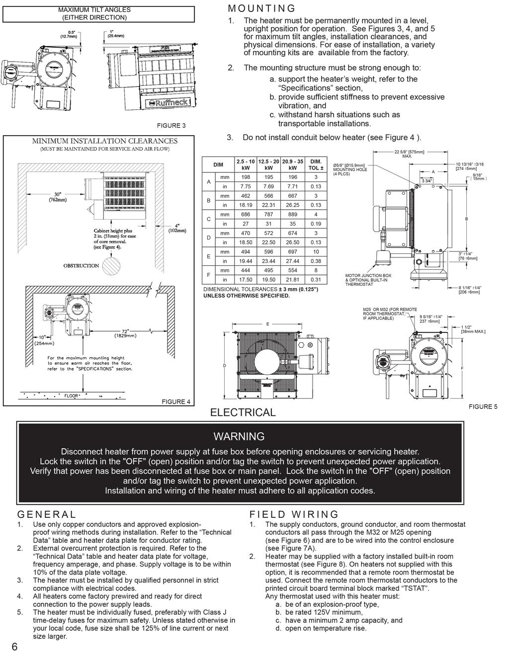
4 IMPORTANT NOTICES WARNING Read and adhere to the following. Failure to do so may result in severe or fatal injury. WARRANTY WILL BE VOID 1. Read and follow all instructions in this manual. 2. Heater is to be used only in atmospheres having an ignition temperature higher than the heater s maximum rated operating temperature as shown on the heater data plate. Refer to applicable electrical codes for additional information. 3. Heater to be used only in the hazardous locations indicated on the heater s data plate. 4. Heater is for dry indoor use only. Do not immerse in water. Do not store or use in areas exposed to rain or snow. 5. Heater is to be connected and serviced only by a qualified electrician experienced with hazardous location equipment. 6. Installation and wiring of the heater must adhere to all applicable codes. 7. Disconnect heater from power supply at fuse box before opening enclosures or servicing heater. Lock the switch in the OFF (open) position and/or tag the switch to prevent unexpected power application. Verify that power has been disconnected at fuse box or main panel. Lock the switch in the OFF (open) position and/or tag the switch to prevent unexpected power application. 8. This heater is equipped with a single bimetal over temperature high-limit. It is of the automatic reset type and therefore the heater may restart without warning. The heater is not to be operated with the high-limit disabled or disconnected from the control circuit. 9. Venting pressure of the pressure relief valve is factory set. Do not tamper with lock nut. 10. Do not tamper or remove warning label indicator on the PRV. 11. Operate the heater only while it is permanently mounted in an upright position. Refer to the Installation - Mechanical section for details. 12. Heater must be kept clean. When operating in a dirty environment, regularly clean the finned tubes, fan, and fan guard. Follow the recommended maintenance procedures. Refer to the Heater Maintenance Checklist section for details. 13. The heater core is vacuum charged and contains propylene glycol. If any fluid leakage occurs from the heater, disconnect it from the power supply and have the core replaced with a factory supplied core. Refer to the Repair and Replacement section for details. 14. Do not operate the heater with any of the louvers fully closed or overriding their stops. 15. Do not operate the heater in atmospheres corrosive to steel or aluminum. 16. Do not operate heater in ambient temperatures above 40 C (104 F). 17. Unused apertures shall be closed with suitable blanking elements. All cable entry devices and blanking elements shall be certified in type of explosion protection flameproof enclosure d, suitable for the conditions of use and correctly installed. 18. Installer to provide certified Ex d sealing fittings and stopping boxes for the same gas groups as the apparatus. 19. The distance from the face of the seal closest to the enclosure (or intended end-use enclosure) and the outside wall of the enclosure (or intended use-enclosure), shall be as small as practical, but in no case more than the size of the conduit or 50 mm, whichever is the lesser. 20. Use factory approved replacement parts only. 21. See applicable electrical codes for seal requirements in field installed conduits. Factory installed conduits require no further sealing. 22. Crackling or pinging noises within the heater core during start up may occur. This is normal. 23. Air discharge near the bottom of the heater may be warmer than the top. This is normal. 24. If there are any questions or concerns regarding the heater, contact the factory. Refer to the last page of this manual for details. 25. Contact original manufacturer for information on the dimensions of the flame proof joints. 26. Heater must be permanently mounted in a level, upright position for operation. See mounting section or mounting instructions label located on the heater's control box. PRV PRV LOCK NUT PRESSURE RELIEF VALVE (PRV) LABEL INDICATOR 4 FIGURE 1
5 TROUBLESHOOTING TIPS 1.0 Heater is not operating 1.1 Check all fuses in heater control box. 1.2 Check remote disconnect switch and circuit breaker. 1.3 Check voltage supplied to the heater refer to the heater data plate for voltage requirements. 1.4 Check thermostat by turning it and check continuity with a multimeter. 1.5 Verify that there is a jumper wire present between terminals 5 and 6 on the terminal block located in the control box. 2.0 Contactor is chattering 2.1 Check supply voltage. 2.2 Check wiring connections. Tighten all loose electrical connections. 2.3 Check thermostat for continuity (See 1.4). If thermostat does not break continuity replace thermostat. 3.0 Contactor is burned or welded 3.1 Check the contactor for burn marks and blackening. Replace the contactor. 3.2 Check incoming power to the heater to ensure there are no voltage fluctuations. 4.0 Heat exchanger is dirty 4.1 Clean the heat exchanger using compressed air PRV has released 5.1 If there are signs that the PRV has released fluid, PRV indicator is broken, blackening around the PRV exit hole, or there are fluid stains visible on the top louver, shut the unit down immediately. 5.2 Check for restricted air flow, bad motor, broken thermostat or malfunctioned high limit. 6.0 Heater is cold on top and warm on bottom 6.1 The core may have lost its vacuum. Check the PRV for signs of loss of fluid and verify that the PRV label indicator is not broken. If PRV has released, send the unit in for repair or replace the core. 6.2 If the PRV does not indicate loss of fluid, the heater should operate normally. Check for loss of fluid on a weekly basis as a minimum. 6.3 The ambient temperature may be too low. If the ambient temperature is very cold the top of the core will be colder than the bottom this is normal. 7.0 Unit cycles on high limit unit turns on and turns off within less than 5 minutes. 7.1 Check and see if the PRV has released fluid. Core may have lost most or all of its fluid. If PRV has released, send the unit in for repair or replace core. 7.2 The core may be dirty, fan may not be working or may be turning the wrong way (the fan must rotate clockwise as seen from the front of the unit) objects may be stuck in the heat exchanger for drying or warming up remove any items from the exchanger. 8.0 The Ground Fault Interrupter (GFI) trips on the main panel, or heater blows fuses. 8.1 Check that you have a fuse of the proper amperage rating. 8.2 Check for loose or frayed wiring. 8.3 If condition is not observable, send heater in for repair. 8.4 Change sensitivity of GFI. 9.0 The fan is turning but very little air comes from the front of the heater. 9.1 Check fan rotation and ensure that the fan turns clockwise as seen from the front of the heater. Refer to the Installation section below for more information. 9.2 Check motor winding resistance and verify that they are balanced. 9.3 Check fan blade set screws to ensure fan blade is not loose on the motor shaft. INSTALLATION The installation instructions provide a general guideline for the installation and wiring of the heater. All applicable local codes must be adhered to. MECHANICAL LOCATION For optimum heating, the heater should be installed as follows: 1. There are no obstructions that may impede the heater s air inlet or discharge. 2. The air discharge is directed into open areas and not at occupants. 3. The air discharge is not directed at a thermostat. 4. The air discharge is directed across areas of heat loss, such as doors and windows (see Figure 2). 5. The air discharge is directed along and at a slight angle toward exterior walls (see Figure 2). 6. If equipment freeze protection is important, direct air discharge at equipment. 7. Air discharge streams support each other and create a circular air flow. It is not required that the heater s air throw reaches the next heater (see Figure 2). FIGURE 2 5
6
 is provided for a supplementary bonding connection where local authorities permit or require such a connection.")
 and code requirements, b.")


7 3. The internal grounding terminal in the control enclosure shall be used as the equipment grounding means. An external bonding terminal (see Figure 6) is provided for a supplementary bonding connection where local authorities permit or require such a connection. M25 or M32 opening for field wiring Fan rotation Rear View of Heater External Bonding Air exits through louvers. Air intake Motor junction box FINAL INSPECTION 1. Before application of electrical power: a. Check that all connections are secured and comply with the applicable wiring diagram (see Figure 9) and code requirements, b. Confirm that the power supply is compatible with the data plate rating of the heater, c. Remove any foreign objects from the heater, d. Install all covers and verify that all enclosures are well secured, and e. Ensure that the fan rotates freely. See Figure 6 for proper direction of fan rotation. Control Enclosure & Field Wiring Contactor load side terminals, this side for factory wiring only. Printed circuit board s terminal block Connect supply conductors to this side of contactor. For a 1-phase heater, use these contactor terminals Active and spare fuses (see parts list) FIGURE 7A Control enclosure and cover FIGURE 6 Optional factory installed built-in room thermostat. FIGURE 8 Remote Room Thermostat if applicable Terminals marked T STAT FIGURE 7B 7
8 TRANSFORMER (tap must match heater voltage) OPTIONAL PILOT LIGHT PCB FUSE MOTOR CONTACTOR AUTO-RESET TEMPERATURE HIGH-LIMIT (THERMOWELL) AUTO-RESET TEMPERATURE HIGH-LIMIT (AMBIENT AIR) OPTIONAL REDUNDANT TEMPERATURE HIGH-LIMIT OPTIONAL ROOM THERMOSTAT ELEMENTS 220/230/240 1-PHASE WIRING SCHEMATIC TRANSFORMER (tap must match heater voltage) OPTIONAL PILOT LIGHT PCB FUSE MOTOR CONTACTOR AUTO-RESET TEMPERATURE HIGH-LIMIT (THERMOWELL) AUTO-RESET TEMPERATURE HIGH-LIMIT (AMBIENT AIR) OPTIONAL REDUNDANT TEMPERATURE HIGH-LIMIT OPTIONAL ROOM THERMOSTAT 380 & Hz 60Hz 50Hz 3-PHASE WIRING SCHEMATIC ELEMENTS TRANSFORMER (tap must match heater voltage) OPTIONAL PILOT LIGHT PCB FUSE CONTACTOR AUTO-RESET TEMPERATURE HIGH-LIMIT (THERMOWELL) AUTO-RESET TEMPERATURE HIGH-LIMIT (AMBIENT AIR) OPTIONAL REDUNDANT TEMPERATURE HIGH-LIMIT OPTIONAL ROOM THERMOSTAT & Hz 60Hz 50Hz ELEMENTS 3-PHASE WIRING SCHEMATIC CONTINUOUS FAN OPTION FIGURE 9
9 FE2 TECHNICAL DATA FOR 50 HZ ELECTRIC AIR HEATERS Model Voltage Nominal Wattage Heater Wattage Phase Max. Motor Nameplate Current (A) Total Current Minimum Circuit Ampacity Supply Wire Maximum Fuse Size Temperature Rise Core Kit Part Number Contactor Part Number (V) (kw) (W) (A) (A) (AWG) (A) C F FE FE FE FE FE FE FE FE FE FE FE FE FE FE FE FE FE FE FE FE FE FE FE FE FE FE FE FE FE FE FE FE FE FE FE NOTES: 1. Minimum conductor size for 30 C (86 F) ambient. Derate conductor for ambient temperature. Use minimum 90 C (194 F) insulation. 2. Heater is functioning normally if at rated voltage the amp draw is within 10% of the value in this table. 3. Operation at lower voltages will result in reduced heat output and amp draw. 4. Add T to model number when adding a built-in thermostat. 5. Add "U" to model number for units with continuous fan option. 6. Add "A" to model number for units with stainless steel cabinet. 9
10 FE2 TECHNICAL DATA FOR 60 HZ ELECTRIC AIR HEATERS Model Voltage Nominal Wattage Heater Wattage Phase Max. Motor Nameplate Current (A) Total Current Minimum Circuit Ampacity Supply Wire Maximum Fuse Size Temperature Rise Core Kit Part Number Contactor Part Number (V) (kw) (W) (A) (A) (AWG) (A) C F FE FE FE FE FE FE FE FE FE FE FE FE FE FE FE FE FE FE FE FE FE FE FE FE NOTES: 1. Minimum conductor size for 30 C (86 F) ambient. Derate conductor for ambient temperature. Use minimum 90 C (194 F) insulation. 2. Heater is functioning normally if at rated voltage the amp draw is within 10% of the value in this table. 3. Operation at lower voltages will result in reduced heat output and amp draw. 4. Add T to model number when adding a built-in thermostat. 5. Add "U" to model number for units with continuous fan option. 6. Add "A" to model number for units with stainless steel cabinet. 10
11 PARTS LIST FORCED AIR ELECTRIC HEATERS Item kw kw kw kw Description 1 ** Core 2 3 Painted: S.S.: Painted: S.S.: Painted: S.S.: Painted: S.S.: Painted: S.S.: Painted: S.S.: Panel, Bottom Panel, Left Side Louver Kit, c/w screws Painted: S.S.: Painted: S.S.: Painted: 3782 S.S.: 9212 Painted: S.S.: Painted: S.S.: Painted: 3783 S.S.: 9213 Painted: S.S.: Painted: S.S.: Painted: 3784 S.S.: 9214 Panel, Top Panel, Right Panel, Fan Shroud Fan Blade Painted: 4078 S.S.: 9504 Painted: 3789 S.S.: 9112 Painted: 3785 S.S.: 9206 Painted: 3788 S.S.: Painted: 4079 S.S.: 9505 Painted: 3789 S.S.: 9112 Painted: 3786 S.S.: 9207 Painted: 3788 S.S.: 9111 Painted: 4080 S.S.: 9506 Painted: 3789 S.S.: 9112 Painted: 3787 S.S.: 9208 Painted: 3788 S.S.: 9111 Fan Guard Kit 220/230/240V 1Ph 50 Hz 220/230/240V 1Ph 60 Hz 380/400/415/440 3Ph 50 Hz 440/480V 3 Ph 60 Hz Bracket, Motor Mount Right Channel, Motor Mount Bracket, Motor Mount Left Coupling, Motor Conduit, Motor Cover, Thermostat Enclosure Conduit, Control Enclosure Conduit, Element Enclosure Enclosure, Element Cover, Element Enclosure 21 Painted: S.S.: Painted: S.S.: Painted: S.S.: Panel, Element Enclosure Guard Enclosure, Thermostat Thermostat, Built-in kit 24 - Enclosure, Control Contactor (60 Hz) (50 Hz) Transformer Bracket, Printed Circuit Board Terminal, 6-14 Ga. Screw Lug Fuse, Buss MDQ - 1/2 Amp Assembly, Printed Circuit Board Cover, Control Enclosure Thermowell, Ambient High-Limit 33 - High Limit, Ambient Temperature Plug, 1" NPT Explosion Proof 35 - Temperature High-Limit Kit 36 Bus-Bar, Straight 37 Provided with Core Kits** Bus-Bar, Small Curved 38 Bus-Bar, Large Curved Terminal, 6-14 Ga Lug, 1/4 Mtg Hole Adapter, 1" NPT to M Adapter, 1" NPT to M25 ** See technical data table for part numbers. Note: For items not shown, contact factory. 11
12 5 HEATER ASSEMBLY DIAGRAM Optional built-in thermostat #23 18 replaces item #16 See control enclosure assembly diagram (below) See high-limit assembly diagram (below) Optional built-in disconnect switch kit 41 CONTROL ENCLOSURE ASSEMBLY DIAGRAM HIGH LIMIT ASSEMBLY DIAGRAM or BUS-BAR CONFIGURATION BUS-BAR CONFIGURATION BUS-BAR CONFIGURATION ALL 1-PHASE MODELS ALL 3-PHASE (EXCEPT 380V & 400V 50 HERTZ) 3-PHASE 380V & 400V 50 HERTZ MODELS ONLY
13 SPECIFICATIONS FOR ALL 50 HZ MODEL Nominal kw to 3.0 to 5.0 to 7.5 to 10 to 13.9 to 20 to 21 to 23.1 Max. Altitude (m) 3,658 2,438 3,048 2,134 3,048 2,134 3,048 2,134 (ft.) 12,000 8,000 10,000 7,000 10,000 7,000 10,000 7,000 Air 21 C (m 3 /hr) F (CFM) Horizontal Air Throw (m) (ft) Max. Mounting Height (m) (to underside) (ft) Motor Power (hp) 1/4 1/2 1/2 (min) (kw) Motor Speed (RPM) Fan Diameter (mm) (in) Net Weight (kg) (lbs) Shipping Weight (kg) Temperature Code Rating Enclosures Motor Type Fan Fan Guard Mounting Holes Heating Elements Temperature High-Limit Control Circuit Optional Built-in Thermostat Control Transformer Contactor Heat Transfer Fluid Cabinet Material Core Conduit Material Overpressure Protection Operational Temperature Limitations Storage Limitations (lbs) T3 (200 C / 392 F) NEMA Type 7 & 9. For dry, indoor use only. Do not immerse in water. Do not store or use in areas exposed to rain or snow. Explosion-proof. Thermally protected. Permanently lubricated ball bearings RPM Aluminum blade. Steel spider and hub with 5/8" ( mm) bore. Split design with close wire spacing. 1/4" (6.3 mm) dia. probe will not enter. Four 5/8" (15.9 mm) diameter holes at top of heater. Three long-life, low watt-density, high grade metal-sheathed elements. Automatic reset type, snap-action bimetal, open on temperature rise. Rated 100,000 cycles at 10 amps, handles amps. 120V, amps, 15VA. (Grounded) Explosion-proof. 2 C to 28 C (36 F to 82 F) Multi-tap primary, 120V secondary, 50VA. 60 or 80 amp. Rated for 1,000,000 mechanical operations. 120V, 15VA coil (separately fuse-protected). Long-life formulated propylene glycol and water 14 gauge (1.90 mm) (0.075") steel. Epoxy coated with five-stage pretreatment, including iron phosphate. Optional stainless steel. Steel with integral aluminum fins, vacuum charged and hermetically sealed. Heavy walled, 0.122" (3.1 mm) steel. Preset 100 psig (690 kpa) pressure relief valve, aluminum body, no field serviceable parts. -20 C to 40 C (-4 F to 104 F) -45 C to 80 C (-49 F to 176 F), short term to 120 C (248 F). Do not immerse in water. Do not exposed to rain or snow. 13
14 SPECIFICATIONS FOR ALL 60 HZ MODEL Nominal kw to 3.0 to 5.0 to 7.5 to 10 to 13.9 to 20 to 21 to 23.1 Max. Altitude (m) 3,658 2,438 3,048 2,134 3,048 2,134 3,048 2,134 (ft.) 12,000 8,000 10,000 7,000 10,000 7,000 10,000 7,000 Air 21 C (m 3 /hr) F (CFM) Horizontal Air Throw (m) (ft) Max. Mounting Height m) (to underside) (ft) Motor Power (hp) 1/4 1/2 1/2 (min) (kw) Motor Speed (RPM) Fan Diameter (mm) (in) Net Weight (kg) (lbs) Shipping Weight (kg) (lbs) Temperature Code Rating Enclosures Motor Type Fan Fan Guard Mounting Holes Heating Elements Temperature High-Limit Control Circuit Optional Built-in Thermostat Control Transformer Contactor Heat Transfer Fluid Cabinet Material Core Conduit Material Overpressure Protection Operational Temperature Limitations Storage Limitations T3 (200 C / 392 F) NEMA Type 7 & 9. For dry, indoor use only. Do not immerse in water. Do not store or use in areas exposed to rain or snow. Explosion-proof. Thermally protected. Permanently lubricated ball bearings RPM Aluminum blade. Steel spider and hub with 5/8 in. ( mm) bore. Split design with close wire spacing. 1/4in. (6.3 mm) dia. Probe will not enter. Four 5/8 in. (15.9 mm) diameter holes at top of heater. Three long-life, low watt-density, high grade metal-sheathed elements. Automatic reset type, snap-action bimetal, open on temperature rise. Rated 100,000 cycles at 10 amps, handles amps. 115 Volts, amps, 15 VA. (Grounded) Explosion-proof. 2ºC to 28ºC (36ºF to 82ºF) Multi-tap primary, 115 V secondary, 50 VA. 60 or 80 amp. Rated for 1,000,000 mechanical operations. 120 Volts, 15 VA coil (separately fuse - protected). Long life formulated ethylene glycol and water 14 ga. (1.90 mm) (0.075in.) steel. Epoxy coated with five-stage pretreatment, including iron phosphate. Steel with integral aluminum fins, vacuum charged and hermetically sealed. Heavy walled, in. (3.1 mm) steel. Preset 100 psig (690 kpa) seep pressure relief valve, aluminum body, no field serviceable parts. -20ºC to 40ºC (-4ºF to 104ºF) -45ºC to 80ºC (-49ºF to 176ºF), short term to 120ºC (248ºF). Do not immerse in water. Do not store or use in areas exposed to rain or snow. 14
 position and/or tag the switch to prevent unexpected power application. Verify that power has been disconnected at fuse box or main panel.")
, b. remove any foreign material from enclosures, c. install and secure all covers, d. ensure that all fasteners are tight, e.")

. 5.")


15 REPAIR & REPLACEMENT WARNING Disconnect heater from power supply at fuse box before opening enclosures or servicing heater. Lock the switch in the OFF (open) position and/or tag the switch to prevent unexpected power application. Verify that power has been disconnected at fuse box or main panel. Lock the switch in the OFF (open) position and/or tag the switch to prevent unexpected power application. Heater surfaces may be hot. 1. After repairing any component: a. check that electrical connections are correct and secure (see Figure 9), b. remove any foreign material from enclosures, c. install and secure all covers, d. ensure that all fasteners are tight, e. remove all foreign objects from heater, and f. ensure air exits through louvers and fan rotates counterclockwise when viewed from rear of heater (see Figure 14). CORE The heater core is vacuum charged and not field repairable. For core removal: 1. Remove cabinet bottom and element enclosure cover. 2. Disconnect all wires entering element enclosure (see Figure 10). 3. Slightly loosen all cabinet bolts shown in Figure 10, to prevent the core from binding. 4. With an assistant supporting the weight of the core, remove the 3 core mounting bolts. Carefully lower the core out of the cabinet (see Figure 11). 5. To return core to factory, use crate supplied with exchange core to protect the element terminals and plate threads. 6. To reinstall, lift the core up into cabinet while an assistant guides the element wires into the element enclosure conduit. 7. Position the core and tighten the 3 core mounting bolts. Tighten the remaining cabinet bolts. TEMPERATURE HIGH-LIMIT 1. Remove temperature high-limit assembly and clean the inside of the thermowell (see Figure 12). A clean thermowell will ensure good thermal contact. 2. Use only a factory supplied temperature high-limit to ensure safe operation. 3. Apply a small drop, 3/32 (2mm) diameter, of heat sink compound to the center of the metal cap but do not spread. This is critical for proper thermal contact between the temperature high-limit and the thermowell (see Figure 12). 4. Reinstall the temperature high-limit assembly with the snap ring and spring into the thermowell without damaging the insulating tube. Secure in place with the cotter pin (see Figure 13). MOTOR, FAN & FAN GUARD 1. Remove bolts holding the motor to the motor mount. On units with a built in thermostat, remove the bolts on the back of the thermostat enclosure. 2. Remove conduit #1 located between motor junction box and control enclosure by turning it in the direction illustrated (see Figure 14). Note conduits #1 and #2 are not interchangeable and have left hand threads on one end, this end is indicated by a machined groove. 3. Remove the 2 piece fan guard assembly (see Figure 15). 4. Lift the motor assembly off the motor mount. 5. Before removing the fan, measure and record the location of the fan hub on the motor shaft (see Figure 16). If difficult to remove, use a gear puller on the fan hub. 6. To reassemble, place motor assembly onto motor mount and fasten the fan guard to cabinet. 7. Simultaneously engage and tighten both ends of conduit #1 into enclosures. Leave a 1/16 to 3/16 (1.6 to 4.8 mm) gap between the motor and fan guard (see Figure 16). Adjust conduit #2 to center the fan in the shroud. 8. To ensure a minimum 5 thread engagement, threaded ends of conduits must protrude a minimum of 1/16 (1.6 mm) into enclosures. The groove on conduit #2 must not be more than 7/8 (22 mm) from motor coupling (see Figure 14). 9. Bolt motor to motor mount. Manually spin the fan blade to ensure fan rotates freely. 10. Air must exit through louvers and fan must rotate counterclockwise when viewed from rear of heater (see Figure 14). Loosen bolts only, do not remove. Conduit Junction Enclosure{ Thermowell Air inlet 7/8 (22 mm) (From groove to face of coupling) Rotation Remove Install Install Conduit #2 Conduit #1 Remove this core mounting bolt & two others on the opposite side. }Loosen bolts only, do remove. not Control Enclosure Element Enclosure FIGURE 10 Remove FIGURE 11 3/32 (2 mm) Drop FIGURE FIGURE 12 FIGURE 13


16 PRINTED CIRCUIT BOARD After removing the printed circuit board (P.C. Board) bracket assembly from the control enclosure, separate the P.C. Board from the bracket by cutting off the plastic spacers (see Figure 18). Reinstall a new factory supplied P.C. Board onto the mounting bracket using new non-conducting spacers of the same length. Spacers are supplied with a new P.C. Board. Reinstall the control circuit ground wire to the printed circuit board bracket (see Figure 9). I N D U S T R I A L C O N TA C T O R 1. Replace with a factory supplied contactor of the same rating Replace with a factory supplied transformer of the same rating. On the new transformer, select primary wires to match heater voltage. Ensure that the correct transformer secondary lead is grounded (see Figure 9). Individually terminate all unused wires using closed end connectors. TRANSFORMER FIGURE 15 FUSE 1. Replace fuse with one of the same type and rating as indicated on P.C. Board or refer to parts list. An extra fuse should be stored in the clips marked SPARE. H E AT I N G E L E M E N T S 1. Heating elements are an integral part of the vacuum charged core. A factory exchange core can be shipped immediately from stock. Refer to Core section for details. C A B I N E T PA N E L S FIGURE Bolt-on cabinet panels are individually replaceable. T H E R M O S TAT C O V E R SCREWS 1. Replace thermostat cover bolts with four plated steel hex head bolts, M6 x 20mm long property class 9.8, 720MPa minimum yield strength. 1/16 to 3/16 (1.6 to 4.8 mm) FIGURE FIGURE 18
17 NOTES 17
18 18 NOTES
19 DIRECTIVE 2003/108/EC AMMENDMENT TO THE DIRECTIVE 2002/96/EC OF THE EUROPEAN PARLIAMENT AND OF THE COUNCIL on waste electrical and electronic equipment (WEEE). 1. The equipment that you bought is WEEE marked and has required the extraction and use of natural resources for its production. It may contain substances that could impact health and the environment. As such it is a requirement not to dispose of WEEE marked equipment as unsorted municipal waste and to collect such WEEE marked equipment separately. 2. In order to avoid the dissemination of those substances in our environment and to diminish the pressure on natural resources, we encourage you to use the appropriate take-back systems in your area. Those systems will reuse or recycle most if not all of the materials of your equipment in a sound way. 3. The crossed-out wheeled bin symbol on this equipment invites you to use those systems. 4. If you need more information on collection, reuse and recycling systems in your area, please contact your local or regional waste management administration.
20 PLEASE ADHERE TO INSTRUCTIONS IN THIS MANUAL Failure to do so may be dangerous and may void certain provisions of your warranty. For further assistance, please call 24hr hotline: (U.S.A. and Canada) Please have model and serial numbers available before calling. WARRANTY: Under normal use the Company warrants to the purchaser that defects in material or workmanship will be repaired or replaced without charge for a period of 36 months from date of shipment. Any claim for warranty must be reported to the sales offi ce where the product was purchased for authorized repair or replacement within the terms of this warranty. Subject to State or Provincial law to the contrary, the Company will not be responsible for any expense for installation, removal from service, transportation, or damages of any type whatsoever, including damages arising from lack of use, business interruptions, or incidental or consequential damages. The Company cannot anticipate or control the conditions of product usage and therefore accepts no responsibility for the safe application and suitability of its products when used alone or in combination with other products. Tests for the safe application and suitability of the products are the sole responsibility of the user. This warranty will be void if, in the judgment of the Company, the damage, failure or defect is the result of: Vibration, radiation, erosion, corrosion, process con - tamination, abnormal process conditions, temperature and pressures, unusual surges or pulsation, fouling, ordinary wear and tear, lack of maintenance, incorrectly applied utilities such as voltage, air, gas, water, and others or any combination of the aforementioned causes not specifi cally allowed for in the design conditions Or, any act or omission by the Purchaser, its agents, servants or independent contractors which for greater certainty, but not so as to limit the generality of the foregoing, includes physical, chemical or mechanical abuse, accident, improper installation of the product, improper storage and handling of the product, improper application or the misalignment of parts. No warranty applies to paint fi nishes except for manufacturing defects apparent within 30 days from the date of installation. The Company neither assumes nor authorizes any person to assume for it any other obligation or liability in connection with the product(s). The Purchaser agrees that all warranty work required after the initial commissioning of the product will be provided only if the Company has been paid by the Purchaser in full accordance with the terms and conditions of the contract. The Purchaser agrees that the Company makes no warranty or guarantee, express, implied or statutory, (including any warranty of merchantability or warranty of fi tness for a particular purpose) written or oral, of the Article or incidental labour, except as is expressed or contained in the agreement herein. LIABILITY: Technical data contained in the catalog or on the website is subject to change without notice. The Company reserves the right to make dimensional and other design changes as required. The Purchaser acknowledges the Company shall not be obligated to modify those articles manufactured before the formulation of the changes in design or improvements of the products by the Company. The Company shall not be liable to compensate or indemnify the Purchaser, end user or any other party against any actions, claims, liabilities, injury, loss, loss of use, loss of business, damages, indirect or consequential damages, demands, penalties, fi nes, expenses (including legal expenses), costs, obligations and causes of action of any kind arising wholly or partly from negligence or omission of the user or the misuse, incorrect application, unsafe application, incorrect storage and handling, incorrect installation, lack of maintenance, improper maintenance or improper operation of products furnished by the Company. Edmonton Oakville Orillia Houston Denver F Roper Road F F F F Alberta, Canada T6B 3E1
Owner s Manual. FX4 Series. Electric Forced Air Heaters for Hazardous Locations
 Owner s Manual FX4 Series ISO 9001 Electric Forced Air Heaters for Hazardous Locations This manual covers the installation, maintenance, repair and replacement parts. approved Locations The Electric Forced
FE2 Series. Installation, Operation, & Maintenance Instructions. Electric Forced Air Heaters for Hazardous Locations. Model Coding
 WARNING! Read all important information notices. Electric Forced Air Heaters for Hazardous Locations FE2 Series Installation, Operation, & Maintenance Instructions Model Coding FE2 220 1 50 025 W T Model
CF1 ProVector Series. Installation, Operation, & Maintenance Instructions. Electric Convection Air Heaters for Hazardous Locations
 WARNING! Read all instructions before installing or using the heater. Please adhere to instructions published in this manual. Failure to do so may be dangerous and may void certain provisions of your warranty.
XT Series Thermostats
 ISO 9001 Explosion-Proof & Moisture Resistant XT Series Thermostats Installation, Operation, & Maintenance Instructions XTWA Thermostat XTWL Thermostat XTB Thermostat Part No.MI133.Rev.2.00 Date of Issue:
BX Series. Installation, Operation, Maintenance Instructions & Spare Parts
 ISO 9001 BX Series Installation, Operation, Maintenance Instructions & Spare Parts WARNING WARNING. The BX convection heater is a heavy duty baseboard designed for use in industrial environments and is
FX5 SD Series Electric Forced Air Heaters for Hazardous Locations
 Owner s Manual FX5 SD Series Electric Forced Air Heaters for Hazardous Locations ISO 9001 This manual covers the installation, maintenance, repair and replacement parts. APPROVED LOCATIONS The Electric
CR1 Triton Series. Owner's Manual. Model Coding IMPORTANT INSTRUCTIONS - SAVE THESE INSTRUCTIONS. Corrosion-Resistant Washdown Unit Heaters
 ISO 9001 IMPORTANT INSTRUCTIONS - SAVE THESE INSTRUCTIONS Read all instructions before installing or using the heater. Please adhere to instructions published in this manual. Failure to do so may be dangerous
D Built-in door interlocking disconnect switch E Monel elements 1st Generation. Heater Kilowatts kw kw kw kw kw
 IMPORTANT INSTRUCTIONS - SAVE THESE INSTRUCTIONS Read all instructions before installing or using the heater. Please adhere to instructions published in this manual. Failure to do so may be dangerous and
OKB, OKD, & OKH Series
 ISO 9001 Infrared Radiant Heaters OKB, OKD, & OKH Series Installation, Operation, Maintenance Instructions & Spare Parts CE Certified HIGH TEMPERATURE, RISK OF FIRE, FIRE/EXPLOSION HAZARD. During operation,
FX5 Series Explosion-Proof Electric Air Heaters
 FX5 Series Explosion-Proof Electric Air Heaters Ruffneck FX5 heaters are C UL US certified for use in hazardous locations. They are designed for the harshest environments such as: dry indoor industrial
FE1 Explosion-Proof Electric Air Heaters
 Explosion-Proof Electric Air Heaters The heater core assembly is contained in a sturdy, epoxy-coated, 14-gauge steel cabinet which also carries the motor and fan assembly. Adjustable louvers allow directional
INSTALLATION, PARTS, SERVICE AND MAINTENANCE MANUAL HEX5 series, electric unit heaters for hazardous locations
 -9. H733A February 00 INSTALLATION, PARTS, SERVICE AND MAINTENANCE MANUAL HEX series, electric unit heaters for hazardous locations This manual covers the installation, maintenance, repairs and parts for
Explosion Resistant Unit Heater Owner s Manual This manual covers installation, maintenance, repair, and replacement parts.
 EXUB Explosion Resistant Unit Heater Owner s Manual This manual covers installation, maintenance, repair, and replacement parts. Forced-Air Heater for Hazardous Locations Class I, Divisions 1 & 2, Groups
 AEU1 Electric Forced-Air Explosion-Proof Heater Owner s Manual, Version: AEU1-OM-B This manual covers installation, maintenance, repair, and replacement parts. Forced-Air Heater for Hazardous Locations
Stars Management JLT SUBMITTAL. EXPLOSION PROOF ELECTRIC AIR HEATER (FX Series)
") Stars Management JLT SUBMITTAL EXPLOSION PROOF ELECTRIC AIR HEATER (FX Series) Tel: 00971 (04) 457 2383 Fax: 00971 (04) 457 2382 P.O. Box: 25867 Dubai U.A.E. E-mail: info@starsmanagementjlt.com Website:
Stars Management JLT SUBMITTAL EXPLOSION PROOF ELECTRIC AIR HEATER (FX Series) Tel: 00971 (04) 457 2383 Fax: 00971 (04) 457 2382 P.O. Box: 25867 Dubai U.A.E. E-mail: info@starsmanagementjlt.com Website:
Brasch Hazardous Location Unit Heaters
 Brasch Hazardous Location Unit Heaters BHUH Features Designed for rugged industrial applications in hazardous locations where the possibility of explosion or fire exists due to the presence of certain
UHIR Series. Horizontal or Vertical Mounting Industrial / Commercial Electric Unit Heater. Owner s Manual
 UHIR Series Horizontal or Vertical Mounting Industrial / Commercial Electric Unit Heater Owner s Manual This manual covers installation, maintenance and repair parts. Read carefully before attempting to
AEU1. Explosion-Proof Electric Air Heater For Hazardous Locations
 AEU1 Explosion-Proof Electric Air Heater For Hazardous Locations 0518 II 2G, Ex d IIB T4 Gb IP55 (ATEX) Ex d IIB T4 Gb IP55 (IECEx) 1ExdIIBT4 X IP55 (EAC Ex) (Suitable for ATEX/IECEx/EAC Ex Zone 1 & 2)
238 Series. Industrial/Commercial Electric Unit Heater. Owner s Manual
 238 Series Industrial/Commercial Electric Unit Heater Owner s Manual This manual covers installation, operation and maintenance. Read carefully before attempting to install, operate or service the 238
FES - Series Portable Electric Heaters. YES - Series Suspended Electric Heaters CONTENTS
 FOSTORIA INDUSTRIES, INC. A DIVISION OF FES - Series Portable Electric Heaters YES - Series Suspended Electric Heaters (FES-1524-3E shown) IMPORTANT SAFETY INFORMATION INSIDE Serious injury or death possible.
WATLOW IND. WATROD Modular Duct Heater Installation & Maintenance Manual I&M NUMBER: Page: 1 Date:6/11/2008 Rev: 2
 I&M NUMBER: 316-42-15-1 Page: 1 _ Pre Installation Check to make sure that heater received is the same as that ordered. Elements may come in contact with each other during shipment. Minor adjustments to
G Series SAVE THESE INSTRUCTIONS. (Model B) Convector Heater for Hazardous Locations GENERAL! INSTALLATION
 Convector Heater for Hazardous Locations GENERAL! INSTALLATION") G Series (Model B) Convector Heater for Hazardous Locations Type G-Series Convection Heaters are designed for use in Class I, Div. I hazardous environments. Units without control options are suitable for
G Series (Model B) Convector Heater for Hazardous Locations Type G-Series Convection Heaters are designed for use in Class I, Div. I hazardous environments. Units without control options are suitable for
 HHP2 Hydronic High Performance Heater CRN: 0H14856.2C Owner s Manual, Part No. HHP2-OM-D This manual covers installation, maintenance, repair, and replacement parts. Industrial Grade Heat-Exchanger Unit
Rev. E 2013 Pentair Technical Products P/N Distributed by: McLean Parts
 PROAIR Water-Cooled Air Conditioner CR43WC Model INSTRUCTION MANUAL Rev. E 2013 Pentair Technical Products P/N 10-1008-167 TABLE OF CONTENTS HANDLING & TESTING THE AIR CONDITIONER...3 INSTALLATION INSTRUCTIONS...4
! The Caution Symbol (exclamation point) alerts you to a "CAUTION", a safety or
 alerts you to a CAUTION, a safety or") I&M NUMBER: 316-42-10-1 Page: 1 Pre Installation Check to make sure that heater received is the same as that ordered. Elements may come in contact with each other during shipment. Minor adjustments to
I&M NUMBER: 316-42-10-1 Page: 1 Pre Installation Check to make sure that heater received is the same as that ordered. Elements may come in contact with each other during shipment. Minor adjustments to
IMPORTANT SAFETY INFORMATION
 OPERATION INSTALLATION PARTS MANUAL www.fostoriaindustries.com Made in U.S.A. ELECTRIC PORTABLE HEATER FES-1024-1CA 08860010 YES-1024-1CA 08861510 FES-1520-3A 08860110 YES-1520-3A 08860810 FES-1524-1A
WATLOW ELECTRIC MFG CO. WATROD Duct Heater (module only) I& M Manual I&M NUMBER: Page: 1 Date: 11/25/2013 Rev: 4.00
 I& M Manual I&M NUMBER: Page: 1 Date: 11/25/2013 Rev: 4.00") I&M NUMBER: 316-42-16-1 Page: 1 Pre Installation Check to make sure that heater received is the same as that ordered. Elements may come in contact with each other during shipment. Minor adjustments to
I&M NUMBER: 316-42-16-1 Page: 1 Pre Installation Check to make sure that heater received is the same as that ordered. Elements may come in contact with each other during shipment. Minor adjustments to
1.0 special notices 2.0 CERTIFICATION
 standard heater applications INSTALLATION & OPERATION INSTRUCTIONS 1.0 special notices CAUTION CAUTION WARNING WARNING 1.1 The following special notices highlight important information in the installation
Operating Instructions & Parts Manual Models 99533, 99532
 Operating Instructions & Parts Manual Models 99533, 99532 2 Please read and save these instructions. Read carefully before attempting to assemble, install, operate or maintain the product described. Protect
INSTALLATION & OPERATING INSTRUCTIONS & PARTS MANUAL
 Heated Air Curtains MODELS: INSTALLATION & OPERATING INSTRUCTIONS & PARTS MANUAL E3606-1125HFD, E3609-1125HFD, E3612-1125HFD E3806-1125HFD, E3809-1125HFD, E3812-1125HFD E4206-1125HFD, E4209-1125HFD, E4212-1125HFD
WATLOW ELECTRIC MFG CO. FIREBAR Screw Plug Installation & Maintenance Manual I&M NUMBER: Page: 1 Date: 11/25/2013 Rev: 4.
 I&M NUMBER: 316-42-3-1 Page: 1 Pre Installation Check to make sure that heater received is the same as that ordered. Elements may come in contact with each other during shipment. Minor adjustments to elements
CR1 Series Triton Corrosion Resistant Washdown Heaters
 CR1 Series Triton Corrosion Resistant Washdown Heaters Ruffneck CR1 Triton Series is a new generation of NEMA 4X corrosion-resistant washdown heaters. The first UL listed Type 4X heater with models ranging
WATLOW IND. WATROD Circulation Heater Installation & Maintenance Manual I&M NUMBER: Page: 1 Date: 6/11/2008 Rev: 2.00
 I&M NUMBER: 316-42-5-1 Page: 1 Pre Installation Check to make sure that heater received is the same as that ordered. Watlow heaters are built to comply with UL and CSA dielectric requirements, it may be
WATLOW IND. WATROD Flange Heater Installation & Maintenance Manual I&M NUMBER: Page: 1 Date:6/11/2008 Rev: 2.00
 I&M NUMBER: 316-42-8-1 Page: 1 _ Pre Installation Check to make sure that heater received is the same as that ordered. Elements may come in contact with each other during shipment. Minor adjustments to
USER S MANUAL BUCKET FAN SERIES BUCKET FAN WHISPER SERIES
 USER S MANUAL BUCKET FAN SERIES BUCKET FAN WHISPER SERIES Bucket Fan 420 Bucket Fan 1055 Bucket Fan 1460 420 1055 1460 2 Bucket Fan CONTENT INTRODUCTION 3 USE 3 WHAT S INCLUDED IN THE BOX 3 DESIGNATION
OCH-SS series Direct Wired Units Indoor * and Outdoor Comfort Heaters
 1200 North Main Street Fostoria, OH 44830 Phone: 800-495-4525 Fax: 419-435-0842 A DIVISION OF www.fostoriaindustries.com OCH-SS series Direct Wired Units Indoor * and Outdoor Comfort Heaters *EXCLUDING
Operator s Manual. IP-100 Immersion Probe Cooler
 Operator s Manual IP-100 Immersion Probe Cooler 110-810 04.27.11 Table of Contents Introduction... 3 General Information... 3 General Safety Information... 3 Safety Recommendations... 4 Unpacking Your
WATLOW IND. FIREBAR Flange Heater Installation & Maintenance Manual I&M NUMBER: Page: 1 Date: 6/11/2008 Rev: 2.00
 I&M NUMBER: 316-42-2-1 Page: 1 Pre Installation Check to make sure that heater received is the same as that ordered. Elements may come in contact with each other during shipment. Minor adjustments to elements
ULTRA-SAFE EXP. Applications E X P L O S I O N - P R O O F H E A T E R S
 ULTRA-SAFE EXP U N I T E X P L O S I O N - P R O O F S Applications Aircraft Hangars/Service Areas hemical Storage/Handling Areas oal Preparation Plants ompressor Stations Grain Elevators Oil Refineries
T-SERIES Air Conditioner. T20 Model INSTRUCTION MANUAL nvent Rev. C P/N
 T-SERIES Air Conditioner T20 Model INSTRUCTION MANUAL Rev. C P/N 89114993 TABLE OF CONTENTS Warranty and Return Policy... 2 IMPORTANT NOTICE... 2 RECEIVING THE AIR CONDITIONER... 3 HANDLING AND TESTING
Air Storm Fans. Air Storm 18 Fiberglass Fan Installation and Operation Manual
 Air Storm 18 Fiberglass Fan Installation and Operation Manual Table of Contents GrowerSELECT General Page...3 Safety...4 Warning Labels...4 Installation...5 Operation Safety...5 Maintenance Safety...5
Comfort. Description. Applications
 Blower Heater 3-35 kw 10,00-119,40 Btuh 40 to 90 Volts, 50/0 Hz 31 Stainless Steel Case Shown 3 Phase ATEX, GOST, CE IIG Exd IIB T3 Description Type is designed to heat areas classified as hazardous locations
CXH-A Forced-Air Heater
 Installation and Operation Instructions CXH-A Forced-Air Heater CXH-A-0 EP to CXH-A-5 EP Class I - Groups C & D, Div. & 2 Class II - Groups E, F & G TB - 65 C (29 F) PF490-6-0242-004 July 20 Table A -
User s Manual and Operating Instructions
 User s Manual and Operating Instructions Model Numbers: CL-36-BDF-A, CL-42-BDF-A, CL-48-BDF-A READ AND SAVE THESE INSTRUCTIONS IMPORTANT: Read and understand all of the directions in this manual before
ELECTRIC FIREPLACE HEATER WITH SINGLE GLASS DOOR
 ELECTRIC FIREPLACE HEATER WITH SINGLE GLASS DOOR Model 91797 ASSEMBLY and Operating Instructions Visit our website at: http://www.harborfreight.com Read this material before using this product. Failure
Three Phase Simplex. Installation (937) Installation Instructions and Operation/Troubleshooting Manual. Installation of Floats.
 Installation Instructions and Operation/Troubleshooting Manual. Installation of Floats.") Three Phase Simplex Installation Instructions and Operation/Troubleshooting Manual This control panel must be installed and serviced by a licensed electrician in accordance with the National Electric Code
Three Phase Simplex Installation Instructions and Operation/Troubleshooting Manual This control panel must be installed and serviced by a licensed electrician in accordance with the National Electric Code
FLCH4R Garage and Utility Electric Heater
 FLCH4R Garage and Utility Electric Heater Installation, Operation & Maintenance Instructions Model No. Volts Amps Watts BTU/HR Phase High Low High Low High Low Min Fuse Size* FLCH4R 208 17.3 8.66 3600
User s Manual and Operating Instructions
 User s Manual and Operating Instructions Model Numbers: CL-30P-DDF, CL-20F-DDF, CL-24O-DDF, CL-30-DDF READ AND SAVE THESE INSTRUCTIONS IMPORTANT: Read and understand all of the directions in this manual
SPECTRACOOL Air Conditioner. N21 Model INSTRUCTION MANUAL nvent Rev. G P/N
 SPECTRACOOL Air Conditioner N21 Model INSTRUCTION MANUAL Rev. G P/N 89115088 TABLE OF CONTENTS WARRANTY AND RETURN POLICY...2 RECEIVING THE AIR CONDITIONER...3 HANDLING AND TESTING THE AIR CONDITIONER...3
T-SERIES Air Conditioner. T43 Model INSTRUCTION MANUAL nvent Rev. I P/N
 T-SERIES Air Conditioner T43 Model INSTRUCTION MANUAL Rev. I P/N 10-1008-145 TABLE OF CONTENTS Warranty and Return Policy...2 IMPORTANT NOTICE...2 RECEIVING THE AIR CONDITIONER...3 HANDLING AND TESTING
T-Series Air Conditioner T15 Model
 INSTRUCTION MANUAL T-Series Air Conditioner T15 Model Protecting Electronics. Exceeding Expectations. McLean Cooling Technology 11611 Business Park Blvd N Champlin, MN 55316 USA Tel 763-323-8200 Fax 763-576-3200
INSTALLATION, OPERATING & MAINTENANCE INSTRUCTIONS FOR 870 SERIES INDUSTRIAL CONTROL PANELS
 INSTALLATION, OPERATING & MAINTENANCE INSTRUCTIONS FOR 870 SERIES INDUSTRIAL CONTROL PANELS GENERAL INDEECO Industrial Control Panels are designed to provide years of trouble free operation if properly
Installation & Maintenance Instructions
 IMPORTANT INSTRUCTIONS READ AND SAVE THESE INSTRUCTIONS Saving energy and creating healthy, comfortable environments No. II-450 Date July, 2015 DRIVE-THRU UNIT 3 AIR CURTAIN SERIES DTU03 for outdoor use
Air Storm Fans. Air Storm 54 Fiberglass Fan Installation and Operation Manual
 Air Storm 54 Fiberglass Fan Installation and Operation Manual Table of Contents GrowerSELECT General Page... 3 Safety... 4 Warning Labels... 4 Installation... 5 Operation Safety... 5 Maintenance Safety...
Installation and Maintenance "L" and "LS" Series
 Installation and Maintenance "L" and "LS" Series IB-43-E This bulletin should be used by experienced personnel as a guide to the installation and maintenance of "L" and "LS" Series ultra capacity float
Inline Heater for Solvent or Gas. Installation and Operation Manual
 SH Series Inline Heater for Solvent or Gas Installation and Operation Manual This instruction manual explains the basic operation of the Process Technology inline solvent or gas heater. We recommend reading
R Series B & T2 Model
 FRONT R Series B & T2 Model Fan Forced Wall Heaters 4-1/4 (108mm) NOTE: Knockouts in top same dimensions 3-1/4 3-1/4 (108mm) (108mm) as bottom 16-7/8 (429mm) 13-7/8 (352mm) BOTTOM 13-7/8 (352mm) 7-3/4
OCH-SSE series Direct Wired Units Indoor * and Outdoor Comfort Heaters
 TPI Corporation P.O. Box 4973 Johnson City, TN 37601 www.tpicorp.com OCH-SSE series Direct Wired Units Indoor * and Outdoor Comfort Heaters *EXCLUDING RESIDENCES IMPORTANT SAFETY INFORMATION INSIDE possible
QUICK PRIME INSTALLATION AND SERVICE MANUAL
 QUICK PRIME INSTALLATION AND SERVICE MANUAL NOTE! To the installer: Please make sure you provide this manual to the owner of the equip ment or to the responsible party who maintains the system. Part #
XC Portable Air Conditioning
 PORTABLE AIR CONDITIONERS XC Portable Air Conditioning XC-14A, XC-22A, XC-30A Models USER & INSTALLATION MANUAL www.xpcc.com 2013 Xtreme Power Conversion Corporation. All rights reserved. Table of Contents
User s Manual and Operating Instructions
 User s Manual and Operating Instructions Model Numbers: PT-18W-DDF-A, PT-20F-DDF-A, PT-20S-DDF, PT-24O-DDF, PT-24-DDF, PT-24-DDF-F, PT-30-DDF, PT-30P-DDF-A, PT-30P-DDF-AF READ AND SAVE THESE INSTRUCTIONS
InstructIon Manual KrEs EQuIPMEnt stands
 Instruction Manual Instruction Manual SELF-CONTAINED AND REMOTE Kairak KRES model refrigerated equipment stand units are available in many lengths from 36 to 120 inches long. These units are available
Air Storm Fans. Air Storm 24 Fiberglass Fan Installation and Operation Manual
 Air Storm 24 Fiberglass Fan Installation and Operation Manual Hog Slat Inc. Newton Grove, NC USA May 2015 Table of Contents GrowerSELECT General Page...3 Safety...4 Warning Labels...4 Installation...5
TORRID MARINE YACHT QUALITY Since Owner s Manual
 Marine Water Heaters Owner s Manual Plumbing Configuration Note: While Torrid Marine is always happy to offer advice, we highly recommend you choose a professional marine technician to install your new
40E ELECTRIC FAN HEATER
 40E ELECTRIC FAN HEATER PRODUCT MANUAL IMPORTANT READ AND UNDERSTAND THIS MANUAL BEFORE ASSEM- BLING, STARTING OR SERVICING THE HEATER. IMPROPER USE OF HEATER CAN CAUSE SERIOUS INJURY. KEEP THIS MANUAL
Electric Space Heater
 The Choice of Professionals Model No. FUH Series Electric Space Heater Installation & Maintenance Instructions SPECIFICATIONS: FUH 54B Heater Rating and Voltage 5000 W @ 40V 465W @ 40V 333W @ 40V 500W
T-Series Air Conditioner T20 Model
 INSTRUCTION MANUAL T-Series Air Conditioner T20 Model Protecting Electronics. Exceeding Expectations. McLean Cooling Technology 11611 Business Park Blvd N Champlin, MN 55316 USA Tel 763-323-8200 Fax 763-576-3200
GRUNDFOS INSTRUCTIONS. Sololift2 C-3. Installation and operating instructions
 GRUNDFOS INSTRUCTIONS Sololift2 C-3 Installation and operating instructions English (US) English (US) Installation and operating instructions Original installation and operating instructions. CONTENTS
CAR-MON DUST COLLECTORS SERIES 207, 2410, 3015
 INSTALLATION-OPERATION-MAINTENANCE CAR-MON DUST COLLECTORS SERIES 207, 2410, 3015 TEFC 3 phase motor Outlet duct Fan wheel housing Inlet duct connection After filter transition Optional after filter unit
The Danger signal indicates an immediately hazardous situation which, if not avoided, will result in death or serious injury.
 The Danger signal indicates an immediately hazardous situation which, if not avoided, will result in death or serious injury. The Warning signal alerts you to potential hazards or unsafe practices which,
INSTALLATION, OPERATION, AND MAINTENANCE MANUAL
 INSTALLATION, OPERATION, AND MAINTENANCE MANUAL TUBE AXIAL FANS BTA, WTA, HTA, DDA The purpose of this manual is to aid in the proper installation and operation of the fans. These instructions are intended
T-Series Air Conditioner T53 Model
 INSTRUCTION MANUAL T-Series Air Conditioner T53 Model Protecting Electronics. Exceeding Expectations. McLean Cooling Technology 11611 Business Park Blvd N Champlin, MN 55316 USA Tel 763-323-8200 Fax 763-576-3200
Ion Genesis II Pump Controller Digital Level Control with Pump Alternation and High Water Alarm
 Page 1 of 8 General Overview Thank you for purchasing an Ion Genesis controller. Take the time to read the instructions carefully before using this appliance. We strongly recommend that you keep this instruction
Ultra-Safe EXP Unit Heater
 INDEEO s ULTRA-SAFE EXP explosion-proof unit heater is designed with both safety and versatility in mind. Unique ULTRA-SAFE EXP features include: Industry s Lowest Ignition Temperature ode Rating: T3,
TURBO Fiberglass Cone Fan and Grill Fan 48'' Belt Drive. Installation & Operator s Instruction Manual
 TURBO Fiberglass Cone Fan and Grill Fan 48'' Belt Drive Installation & Operator s Instruction Manual July 1998 MV1383B Chore-Time TURBO TM Fan Extended Warranty Chore-Time Equipment warrants new TURBO
PROAIR Water-Cooled Air Conditioner. CR43WC Model INSTRUCTION MANUAL
 PROAIR Water-Cooled Air Conditioner CR43WC Model INSTRUCTION MANUAL Rev. F 2018 nvent P/N 10-1008-167 87976466 TABLE OF CONTENTS HANDLING & TESTING THE AIR CONDITIONER...3 INSTALLATION INSTRUCTIONS...4
24 & 30 Quiet Design Oscillating Wall Mount Fan
 Operating Instructions & Parts Manual Models: 99538, 99539 Please read and save these instructions. Read carefully before attempting to assemble, install, operate or maintain the product described. Protect
Installation & Maintenance Instructions
 Portable High Temperature Blower Attention: Do not operate this heater in explosive areas. Installation & Maintenance Instructions Dear Owner, Congratulations! Thank you for purchasing this new heater
INSTALLATION, OPERATION AND MAINTENANCE INSTRUCTIONS FOR PIPE THREAD IMMERSION HEATERS USED IN HAZARDOUS LOCATIONS
 INSTALLATION, OPERATION AND MAINTENANCE INSTRUCTIONS FOR PIPE THREAD IMMERSION HEATERS USED IN HAZARDOUS LOCATIONS I. GENERAL Heatrex Explosion-proof Pipe Thread Mounted Immersion Heaters are CSA approved
INSTALLATION, OPERATION AND MAINTENANCE
 INLINE HEATER INSTALLATION, OPERATION AND MAINTENANCE MODELS: ILS SERIES 1.5kW 120V SINGLE PHASE BEFORE YOU BEGIN CHECK ALL ELECTRICAL CONNECTIONS TO ALL COMPONENTS WITHIN THE HEATER FOR TIGHTNESS. CONNECTIONS
QUICK PRIME INSTALLATION AND SERVICE MANUAL
 QUICK PRIME INSTALLATION AND SERVICE MANUAL NOTE! To the installer: Please make sure you provide this manual to the owner of the equip ment or to the responsible party who maintains the system. Part #
Single Phase Simplex SXL21=3, SXL24=3, SXH21=3, and SXH24=3
 Single Phase Simplex SXL21=3, SXL24=3, SXH21=3, and SXH24=3 Manufactured by SJE-Rhombus Installation Instructions and Operation/Troubleshooting Manual 7000 Apple Tree Avenue Bergen, New York 14416 Phone:
CELDEK Evaporative Cooler Module Installation, Operation, and Maintenance Manual. CELDEK Evaporative Cooler
 CELDEK Evaporative Cooler Module Installation, Operation, and Maintenance Manual CELDEK Evaporative Cooler RECEIVING AND INSPECTION Upon receiving unit, check for any interior and exterior damage, and
T-SERIES Air Conditioner. T50 Model INSTRUCTION MANUAL nvent Rev. F P/N
 T-SERIES Air Conditioner T50 Model INSTRUCTION MANUAL Rev. F P/N 10-1008-203 TABLE OF CONTENTS Warranty and Return Policy...2 RECEIVING THE AIR CONDITIONER...3 HANDLING AND TESTING THE AIR CONDITIONER...3
18E ELECTRIC FAN HEATER
 18E ELECTRIC FAN HEATER MODEL 18E-1 (Single Phase) MODEL 18E-3 (Three Phase) PRODUCT MANUAL IMPORTANT READ AND UNDERSTAND THIS MANUAL BEFORE ASSEM- BLING, STARTING OR SERVICING THE HEATER. IMPROPER USE
INSTALLATION, OPERATING & MAINTENANCE INSTRUCTIONS FOR 350 SERIES CIRCULATION HEATERS
 INDEECO Circulation Heaters are designed to provide years of trouble free operation if properly installed and maintained. Please read and follow these instructions for installing and maintaining the heater.
CPL Series Pedestal Convection Heater
 Installation Instructions and RENEWAL PARTS IDENTIFICATION CPL Series Pedestal Convection Heater MODEL CPLAS (H=5-1/2, D=3 ) CAT. LENGTH WATTS/ TOTAL AMPERAGE NO.* L Ft. WATTS 120V 208V 240V 277V 2125
USER S MANUAL. Heat Recovery Ventilator. Vents Brig HRV 200 Vents Brig HRV 300
 USER S MANUAL Heat Recovery Ventilator Vents Brig HRV 200 Vents Brig HRV 300 2 Brig HRV 200 (300) CONTENT Introduction... 3 Application... 3 Delivery set... 3 Unit designation key... 4 Basic unit dimensions...
KNHE48 SERIES WATER-TO-AIR HEAT EXCHANGER
 Keep This Manual With Heat Exchanger Find additional information on this model at kooltronic.com or use the Technical Documents QR code below. Technical Documents KNHE48 SERIES WATER-TO-AIR HEAT EXCHANGER
(3 plastic wire connectors,blade balancing kit, 2 extra mounting screws #10-32 for outlet box.)
") Excel Lighting & Manufacturing Ltd. Lifetime Limited Warranty Excel Lighting & Manufacturing Ltd. Warrants the fan motor to be free from defects in workmanship and material present at time of shipment
Excel Lighting & Manufacturing Ltd. Lifetime Limited Warranty Excel Lighting & Manufacturing Ltd. Warrants the fan motor to be free from defects in workmanship and material present at time of shipment
KPHE24 SERIES WATER-TO-AIR HEAT EXCHANGER
 Keep This Manual With Heat Exchanger Find additional information on this model at kooltronic.com or use the Technical Documents QR code below. Technical Documents KPHE24 SERIES WATER-TO-AIR HEAT EXCHANGER
User s Manual & Operating Instructions
 User s Manual & Operating Instructions Model Numbers REM-03-240-GH / REM-05-240-GH CONSUMER: READ AND SAVE THESE INSTRUCTIONS Use this heater only as described in this manual. Any other use not recommended
IMPORTANT SAFETY INFORMATION:
 Owner s Manual Model CUH05B31T IMPORTANT SAFETY INFORMATION: Always read this manual first before attempting to install or use this heater. For your safety, always comply with all warnings and safety instructions
Quest PowerHeat HFC 100 Pro
 Quest PowerHeat HFC 100 Pro Installation, Operation and Maintenance Instructions Read and Save These Instructions This manual is provided to acquaint you with the portable fan coil so that installation,
Installation & Maintenance Instructions
 PRH Series Plenum Heaters Installation & Maintenance Instructions Dear Owner, Congratulations! Thank you for purchasing this new heater manufactured by Marley Engineered Products. You have made a wise
M Series Fan Filter Units
 M Series Fan Filter Units Product Specifications... 2 Safety Instructions... 3 Receiving and Unpacking... 3 Pre-Installation Instructions... 3-4 Installation Instructions... 4 Electrical Installation Instructions...
Installation, Operation & Service Manual
 Installation, Operation & Service Manual WARNING Improper installation, adjustment, alteration, service or maintenance can result in death, injury or property damage. Read the Installation, Operation and
Installation, Operation and. Maintenance Instructions
 Installation, Operation and Maintenance Instructions DIVISION 4 SALES REFERENCE DATE SERVICE REFERENCE (Supersedes Ogden Manual 35) JULY, 2004 K Series: Tubular Style Elements Industrial Flanged Immersion
GENESIS Air Conditioners. All Models INSTRUCTION MANUAL nvent Rev. K P/N
 GENESIS Air Conditioners All Models INSTRUCTION MANUAL Rev. K P/N 89104462 TABLE OF CONTENTS Warranty and Return Policy...2 RECEIVING THE AIR CONDITIONER...3 HANDLING AND TESTING THE AIR CONDITIONER...3
40E ELECTRIC FAN HEATER
 40E ELECTRIC FAN HEATER PRODUCT MANUAL IMPORTANT READ AND UNDERSTAND THIS MANUAL BEFORE ASSEM- BLING, STARTING OR SERVICING THE HEATER. IMPROPER USE OF HEATER CAN CAUSE SERIOUS INJURY. KEEP THIS MANUAL