User manual and Installation Guide AHU-400 BV AHU-400 BH
|
|
|
- Estella Banks
- 5 years ago
- Views:
Transcription


1 User manual and Installation Guide AHU-400 BV AHU-400 BH


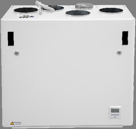
2 User manual. Page 1 to 13 (Pictures on pages 1 5 shows AHU 400 BV) To open the front hatch you will find a key for the quarter turn latches in the folder together with the following documents. Keep this key in a place so it is out of reach for children. To open the locks, turn the key toward the center of the unit. Left latch Right latch To close, after putting the hatch back on place, turn the latches the opposite way. You may use some pressure towards the hatch to close it. Be careful that the door can "be stuck" in the sealing on the hatch. For easier loosening of the hatch, release it first in one corner at the top. To operate this product people should have necessary skills, or under the supervision of a qualified person. Children should be told to not play with the appliance. When you lift off the front hatch from the device, make sure the spiral cable that connects the device and the front hatch is not overstretching for a long period. This can damage the cable During commisioning of the appliance, when installed, the spiral cable has to connected in order to have access the control panel in front of the hatch. When servicing and cleaning, this spiral cable should be disconnected. Make sure that the spiral cable is disconnected and connected without the use of force. This to prevent contacts on cable to be damaged. If the spiral cable is out of position, then you will get an alarm called "Low voltage". To get the signal back into the display you must unplug and plug back in both hatch and ventilation unit. Note! If the spiral cable is broken, you have to order new original cable from supplier. Standard cable from store would not work. New spiral cable has art.no: from supplier. We reserve the right to change technical data without notice. Page 1


3 Before any access into the electrical connections boxes, power must be disconnected by pulling out the plug from the socket. It is only allowed for authorized persons to enter into the electrical connection boxes. If any electrical components are damaged, they must be replaced by the manufacturer, dealer or a qualified person in order to avoid dangerous situations.. Adjustment of the unit. A humidity sensor is, from factory, mounted inside the unit. It is set to 0 that means it is set to not active. After startup, where the unit is placed into a new building with high humidity, you can let this humidity sensor be turned off for a period to avoid the full speed of the fan at night. To get the humidity sensor to operate as intended, you need at one time to put it active. Than you need to set the switch in position "1". If the ventilation unit is placed in a house without high humidity, you should switch to position "1" after you putting ventilation unit into operation. This switch will also affect any extra external humidity sensor that is plugged into the device. Adjusting the humidity sensor. If it is necessary to adjust the sensitivity of the humidity sensor then you must, on older models, remove the cover, which is over the control board where this adjustment is located. Unplug the supply before removing the cover. On newer models, you just can remove the black plug and you then can see the adjusting knob and the RH% scale. Pictures shows AHU 400 BV We reserve the right to change technical data without notice. Page 2
 to 90% (high) in accordance to what are the needs. The arrow points the value chosen.")

4 The sensor is set to 80% RH from factory. If you do adjustments, this only affect the sensor integated inside the unit. The sensitivity for the integrated sensor you can adjusted from 50% (low) to 90% (high) in accordance to what are the needs. The arrow points the value chosen. If you have a second external sensor that means you need to adjust that one from its settings. Replace the cover and / or plug after finish adjusting. Replacing the filter. The filters should be replaced every or 12. months. Should be extracted without use of any tools.. Remember to enter the control panel menu (4.3 Filter) and press Filter OK after the filters has been replaced. To guarantee optimal properties of the ventilation unit, use the original filters from EnSy. The use of spurious filters will limit the warranty on the product. Ensy art number for filter set is: SET FILTRE ENSY AHU 350 BV/BH _BL/BR_BV/BH. F7: 165x370x94 We reserve the right to change technical data without notice. Page 3


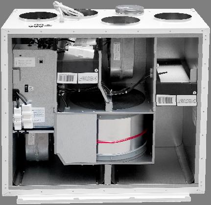
5 Cleaning the fans. AHU 400 BV A qualified person must do this. Disconnect the 3 pole and 5 pole plugs. Before you can pull out the fans, you have to remove the brackets that holds the fans in correct position. Important that these brackets is placed back after cleaning. Clean with mild soap and water. AHU 400 BH A qualified person must do this. Disconnect the 3 pole and 5 pole plugs. The supply air fan can be pulled out of the ventilation unit without the need for any tools. Before you can pull out the extraxt air fan, you have to remove the bracket that holds the fan in correct position. Important that this bracket is placed back after cleaning Clean with mild soap and water We reserve the right to change technical data without notice. Page 4


6 Maintenance and cleaning of rotary heat exchanger This must be done by a qualified person. Disconnect the 3 pole plug. Can be pulled out of the ventilation unit without the need for any tools. Rotor exchanger can easily be removed for cleaning by dissolving the 14 screws that hold it together. Clean parts with mild soap and water. Do not expose the rotor motor or connector for moisture. The exchanger you also can clean with mild soap and water. Do not use ammonia containing detergent, as this will prey on and discolor aluminum in rotary heat exchanger. Flushed with hand shower and blow gently clean with compressed air. Ensure that the screws are tightened sufficiently so that they do not come loose during operation. Preferably use a screwdriver to tight the screws. If use of electrical screwdriver, make sure that you use low torque to prevent destroying the springs in the sheet metal parts. To make sure that the drive belt can adjust itself into correct position you must rotate the exchanger some few turns. Then insert back into the ventilation unit. Be sure that rotor exchanger is properly inserted in all the guides inside the unit. If not, this can lead to vibration in the system and internal air leak in the unit. We reserve the right to change technical data without notice. Page 5


7 Main menu Indicators in the menu screen: "Sun" indicates that the rotor has stopped, the air handling unit is in the summer operation mode. "Snowflake" low temperature indicates that the air handling unit is in defrosting mode. "Steaming pot" and blinking fan blades indicates that the kitchen exhaust is activated. Control Button Control Button indicator for fan. 2. Control Button indicator set point. 3. Control Button indicator information. 4. Control Button indicator settings. Overview of control panel The main screen consists of, from top, left: Time Indication, hour, minute Timer, Weekly schedule (if programmed) Reheating coil (if connected) Temperature readings, Outdoor / Indoor Status airflow fan speed setting OFF MIN NORM or MAX Temperature set point, C Reheating coil (here refers active element) Rotary exchanger Indicator (here refers active rotary wheel) "Timer" and the countdown of the fan symbol indicate that the forced ventilation is enabled. From 10 up to 240 minutes "Away" indicates when the feature is enabled, this feature will override timer. "Clock over the fan symbol" indicates that the timer is activated. Co2 over the fan symbol" indicates that the carbon sensor is activated. "Exclamation point" indicates that moisture recorded over the sensor is higher than the set value. May also indicate that the motion sensor is activated if connected on D2 signal output. This symbol indicates that the rotary heat exchanger is activated and will be rotated We reserve the right to change technical data without notice. Page 6
8 1.Fan speed Ventilation unit has three options for choice of airflow. You can see that the fan are running with Max speed and the clock will start countdown. You can easy deactivate the fan boost again before the countdown automatically stops it. Min, Normal and Max. For programming of values within each step, see Using the control button 1, and / + buttons can change between the preprogrammed selections. 1.1 Fan boost Forced ventilation, fan speed increases to max speed. (Means to the speed that is set in menu ) The function is for use if high humidity in bathrooms and laundry room. First control buttom 1 and then 4. This feature can also be operated with an external pulse switch. The switch is placed in the bathroom or adjacent rooms. Connected to contact D1 in top of the ventilation unit. (Look at page 23 in this manual.) If this option via D1 is intended for use against wood stove or fireplace then it is recommended that Max speed under Fan control in menu is set to Supply 100% and adjust Extract to be 80 to 85%. (Look at page 10 in this manual) 2. Temperature Choose from pre programmed temperature settings set point between C. Setting is changed by operating the switch buttons below / + symbols. Forced ventilation can be activated with button then Interval adjustable from min with + and Indicator for activated heating coil. Small picture show not activated. Heating element can here be set ON or OFF by operating the switch button 4 in this screen, but only if heater is connected. This picture shows 10 min forcing time, but not activated. To activate the fan boost use control button 4. (To see if heating coil is connected or disconnected, see Heater) We reserve the right to change technical data without notice. Page 7
 Here you can see defrost mode that has been chosen. (See 4.5.1.9 if you want to change mode.) 3. Information / 3.")
9 3. Information. 3. Information / 3.3. General info 3. Information / 3.1.Alarms When alarm you can find a source of error here, as well as info on how the alarm is reset. (See pages 28 and 29 in this manual) Here you can see defrost mode that has been chosen. (See if you want to change mode.) 3. Information / 3.2 Program version Information about the software version. This information must be provided to service personnel at the failure of the unit. 4. Preferences To navigate within the various sub menus when using the control buttons below the up / down cursor key that displays on the display. Which display is defined as Display 1 or Display 2 appears here if the plant has mounted two displays. See selection of the displays. 4. Preferences / 4.1 Time/date Setting menu for Time/date. This setting is important since the information forming the basis for the weekly schedule function if this is to be activated. Also for the filter alarm function it is needed. We reserve the right to change technical data without notice. Page 8
10 4. Preferences / 4.2 Weekly schedule Programming of the Weekly schedule, fan speed and temperature set point. Here it can be programmed for two periods each day. Ex. day night. 4. Preferences / 4.3 Filter Setting the time interval for filter change, current choices are 6, 9 or 12 months. Make your choices by using the cursor keys + /. Start time Stop time Fan speed Alarm reset elapsed period by pressing the menu button 4, under "Filter OK" Activation of the period. Here not active Every day must be programmed individually. Monday a period of time, select the start time. To activate the period, X over period number is removed, use the / + keys. 4. Preferences / 4.4 Adjust Screen Adjusting the contrast and color on the display. Use enter to move between the different fields. You can also adjust how long it should be light in the display after the operation. 4. Preferences / 4.5 Setup Choose airflow (fan speed) Speed dialing MIN when one fan blade on the indicator is black. NORM = two black fan blades on the indicator. MAX speed = three black fan blades on the indicator. Select the desired supply air temperature you want during the period. Settings between C. If weekly schedule looks something like this without any reason then you must punch in all the data again. It do not help to update software. To proceed, use PIN code 1000 Press + once till it shows 1000 in display. Then press 4 times on Then press button 3 for OK.. We reserve the right to change technical data without notice. Page 9

11 4.5.1 Setup Fan control Factory settings for AHU 400 BV and BH you can see in next picture Heater Turning on/off the reheating coil, use the minus or plus button to change settings. The installer can adjust these settings so that it is adequately balanced ventilation Co2 control If the unit shall be connected CO² control then connect it to C0² connector on top of the unit. (See page 23 in this manual). Menu for enabling / disabling of CO² control. Scroll to Off and press + to activate. On Cooling recovery Activation of the cooling recovery: Here you preprogrammed wanted ppm value and the boost speed for the fans. Note: To get balanced ventilation is a prerequisite that Supply and Extract air fan has the same value as the MAX value under It is pre programmed two options for use when the outside temperature is higher than the indoor temperature, heat recovery system will activate the function start and supply air will be cooled by exhaust air. Engagement when the outdoor temperature is 2 C or 3 C higher than room temperature. Use button 4 to change setting for Off. Press + to activate (On). Use button 4 to change setting for 2 C. Press + to change to to 3 C, if wanted Cooker hood Menu for programming of fan speeds by activation of the kitchen hood. KV connector on the top of the unit (see page 23 in this manual) should always get signal from the kitchen hood when this is activated. This to prevent rotor alarm. We reserve the right to change technical data without notice. Page 10
12 Absent Menu for setting the desired values by activating away / home function. Supply and Extract air should have the same value as the MAX value under (Set to 100% from factory.) Even if it is installed an "active" kitchen ventilator with piping not connected towards the unit, the KV plug must get the signal to see that kitchen ventilator is activated. This can be done by using a a pressure switch in the exhaust tube from the ventilator. Then Extract set down to around 50% or less to compensate for the extract air in the hood. Note! If KV signal plug is not in use for cooker hood then you can use the signal to get more supply air when to fire up a fireplace. Then adjust so that supply air delivers more air than extract air fan. In this case you must use a switch and not impulse switch Extern alarm If the unit has been connected to an external humidity sensor or motion sensor. Use the D2 connector on top of the unit. (See page 23 in this manual). Note! In order for this feature to work, you need the one pole switch marked RH% ON / OFF inside the unit to be set in position 1. (See page 2 of this manual for the location of this switch). Supply and Extract air should have the same value as the MAX value under (Set to 100% from factory.) Use the D3 connector on top of the unit. (See page 23 in this manual) Function is operated via an external switch. Set value of the desired temperature will show in the display after activating the function Calibration Menu reading of embedded temperature sensors. These temperature sensors are delivered calibrated from the manufacturer and should not be attempted change in here. The «Outside air» sensor normally shows 3 6 C highter temperaature then the reel outside temperature. This is due to heating of the air in the duct network from the intake grille to the intake of the unit where the sensor are placed We reserve the right to change technical data without notice. Page 11
13 Defrost Menu for how to change defrost mode if temperature is low and humidity is height. Modus 1: at low humidity. Defrosting function start at 20 C. From the start up menu you can see which defrost mode the unit is set in. Modus 2: at normal humidity. Defrosting function start at 15 C. The unit is set in mode OFF from factory. If it is needed to change the defrost mode to another mode then press button 4 and scroll down to Configuration with button 3. Modus 3: at high humidity. Defrosting function start at 10 C. Press enter button and follow procedure as in Menu 4.5 Setup to continue. The function when defrosting starts is that each hour the supply air fan stops for 6 minutes. The heater EV turns off. Extract air fan reduces speed to 30% and the rotary exchanger will run as normal. To avoid that the rotary exchanger will stop when the cycle goes back to normal function, the supply air fan will start up the last minute of the defrosting mode cycle. Press enter button Defrost mode OFF from factory. (Supply air fan reacts delayed relative to the control signals and rotary exchanger so that the heater will not engage until the speed of the supply air fan has passed 250 r/min, in normal operation). We reserve the right to change technical data without notice. Page 12
14 Display number If two control panels should be used, then from this menu it has to be specified that one of the control panels is «Display 1» and the other one is «Display 2». This to avoid delay in the signals between the control panels and main control board inside the unit. It does not matter which of the control panels that are called Display 1 or Display 2. We reserve the right to change technical data without notice. Page 13
15 Table of contents: 1. General 2. Mounting of the unit 2.1 Brackets and gaskets to avoid vibration 2.2 Stopper brackets 2.3 Mounting of cooker hood 2.4 Duct cover 2.5 Dimensions and technical data 3. Connections 3.1 Electrical connections 3.2 Duct connections 4. Setting the airflow 5. Alarms 1. General Mounting instructions. Page 14 to 27. This guide is made to provide installation and user instructions regarding the correct installation of AHU 400 BV and BH. AHU 400 BV and BH is designed for heat recovery with air volumes of up to 400 m³ / h. The energy from the exhaust air is transferred to supply air through the rotary heat exchanger where the air streams pass each other without making contact. The unit has a built in heater for supplementary heating of supply air. Humidity sensor for forced ventilation is integrated into ventilation unit. Control panel is integrated into the front hatch. Option for a second control panel to be connected is made outside the unit. The unit can also connect additional equipment cooker hood over the stove, pulse switch for controlling the forced ventilation, for example, wet rooms or bathrooms, sensor for carbon management and switch management away / home function. Control of these options are integrated into AHU 400 BV and BH. AHU 400 BV and BH is supplied in painted finish, tested and ready for operation. Installation, commissioning and tuning must be performed by authorized personnel. 2. Mounting Together with the unit is delivered the following equipment: 1. Suspension bracket and stoppers 2. Wall Bracket with vibration dampening gasket 3. Self adhesive vibration damping 4. Accessories bag containing the necessary screws 5. 5 pcs. plugs for connecting additional equipment. 6. Key for opening the front hatch. We reserve the right to change technical data without notice. Page 14

 We reserve the right to change technical data without notice. http://www.")
16 First, select how the unit should be mounted so that the piping system should be as easy as possible. Supply air to room Fresh air from outside Exhaust air Cooker hood Extract air from room (Sketch over show AHU 400 BV) Extract air from room Cooker hood Exhaust air Fresh air from outside Supply air to room (Sketch over show AHU 400 BH) We reserve the right to change technical data without notice. Page 15


 Make sure that the edge protection gasket is")
17 The unit can also be placed on the floor. It is then important that there are placed at least 50 mm insulation under the unit to prevent vibration to the building. If ventilation unit will be placed as the sketch shows it must not be covered so that service is prevented. If placed at the attic make sure that there are at least 500 mm clearance over the front hatch so there will be room for service. 2.1 Brackets and vibration gasket Suspension bracket screwed on top of the unit as shown. Use 8 pcs M5 x 16mm, supplied with the unit (Sketch over show AHU 400 BV) Make sure that the edge protection gasket is placed on the wall bracket. We reserve the right to change technical data without notice. Page 16


18 To get the unit in right position use the following brackets and screws. In order to relief the hanger bracket on the top it is important however also to mount the bracket to be under the unit. Ensure that the screws hit the beams behind the wall if the unit is to be hung on a light wall. Use 6 pcs wood screws 5 x 40mm, supplied with the unit, for each bracketmonter veggfestet med vibrasjonspakning. Påse at vibrasjonspakningen er intakt. Mount the wall bracket with vibration gasket. Be sure that the vibration gasket is intact Glue vibration gasket to the back of the unit, see illustration. Approx. 60mm from the bottom of the unit. 2.2 Stopper brackets To prevent the unit to be lifted out of the brackets should be installed two stoppers. Use two pcs of wood screws 5 x 40mm, supplied with the unit, for each bracket. In order not to transmit vibration, it is glued vibration material on these brackets We reserve the right to change technical data without notice. Page 17

 We reserve the right to change technical data without notice. http://www.ensy.")
19 2.3 Mounting of cooker hood If kitchen exhaust hood is to be used together with the unit If kitchen exhaust hood is to be connected into the top of the unit, you must remove the end cap in the top that is marked COOKER HOOD (Sketch shows AHU 400 BV) (Sketch shows AHU 400 BH) We reserve the right to change technical data without notice. Page 18

 The instruction how to mount this duct cover you will find together with the duct")
20 2.4 Duct cover If you want to use a duct cover to hide the pipings you will need the distance 296 mm from the roof and down to the top of unit. The duct cover has to be ordered separately from supplier. (Art: ) The instruction how to mount this duct cover you will find together with the duct cover. We reserve the right to change technical data without notice. Page 19
 (Sketch shows AHU 400 BH) All")


21 2.5 Dimensions (Sketch shows AHU 400 BV) (Sketch shows AHU 400 BH) All ducts are Ø160 mm except the one for the cooker hood. That one is Ø125 mm. We reserve the right to change technical data without notice. Page 20
22 TECHNICAL DATA Reheating unit + fans phase/voltage (50Hz/VAC) ~1 / 230 effekt forbruk (W) 1540 Recommended fuses (A) 10 Control system Filter Class Superpleat F7 IP class Thermal/sound insulation Sidewall, back, top and bottom. In front hatch Ventilation unit with closed front door Ventilation unit with open front door (mm) Weight, including brackets (kg) 64,5 Integrated IP 4X IP 2X SPECIFICATIONS: Rotary heat exchanger with heat recovery up to 85 % efficiency. Electric heating coil. High efficiency and low noise EC fans. Adjustable 30 to 100 % speed. Adjustable supply air temperature between 15 and 21 C. Acoustic and thermal insulated housing. Integrated control system with "Touch Panel" for the control of the unit supplied as standard. The unit is designed for optional connection of a cooker hood in top of the unit. In top of the unit there is: (Look at page 23) Junction point of contact for connection for an extra control panel. Junction point of contact for cooker hood. (KV) Junction point of contact for Co² sensor. (CO ²) Junction point of contact for puls switch. (D1) Junction point of contact for an external humidity sensor or motion detector. (D2) Junction point of contact for connection for home / away function. (D3) ACCESSORIES: Extra control panel, desire more control points. Including 10meters signal cable (Art. no: ) Duct Cover for the encapsulation piping in the top. (Art. no: ) Wireless puls switch. (Art. no: ) COOKER HOOD. WHITE SLIM with LED Downlights (Art.no: ) COOKER HOOD. Stainless steel SLIM with LED Downlights (Art.no: ) We reserve the right to change technical data without notice. Page 21


 to ensure easy access")


23 Demand controlled ventilation adequate air quality Control panel: Extra control panel placed at a suitable place in the building to do the monitoring and regulation of ventilation as simple as possible. Must not be placed in bathrooms or wet area. The control panel should be mounted on the wall. Motion Detector: When installed in a living room, this will give the signal to the unit to increase speed to max airflow. Humidity sensor: Humidity sensor for forced ventilation is integrated into ventilation unit. Air handling units should be located in suitable rooms in central residence (utility / laundry room) to ensure easy access for service and filter change. If mounted in wet rooms or bathroom then the contact points must be sealed so that it can not penetrate water. This is especially for CO2, KV, D1, D2, D3 and RJ connectors The unit is designed for connection of external kitchen hood. This is an alternative solution if problems with piping from cooker hood through the outer wall. Stove / Fireplace / Bathroom Wireless control panel / pulse switch can be used to increase supply by use of a stove. Mounted in a suitable location in relation to the unit. Can also be placed near the bathroom for easy operation by forced ventilation (max airflow) CO² sensor: Can be installed in the living room and will give signal to the unit if the pollution level in the room is too hight. We reserve the right to change technical data without notice. Page 22


 (Sketch")
24 3. Connections 3.1 Electrical connections AHU 400 BV and BH is supplied with approximately 1.7 m cable and plug for 10A / 230V outlet. Extra control panel: The control panel comes complete with signal cable, length 10m. The signal cable to the control panel must have at least 10 cm distance to high voltage cables The control panel is put into a box and can be attached directly to the wall. Make a suitable hole for the wire in the recess for wire in the box. The control panel can also where concealed wiring be attached to standard wall box where the fastening screws in the wall box have 60 mm cc. In order to dismantle the "touchpad" disc and display this can easily be done by using a knife with thin blade gently inserted between the jacket and the front plate. Then flip the knife down so that the frame loosens. When installing this extra control panel, remember to define it as Display 2. Look at page 13 in this manual. Connections of sensors / external functions See the following wiring diagram for details (Sketch shows AHU 400 BH) (Sketch shows AHU 400 BV) Plugs for connecting external sensors you find in the accessories bag supplied with the unit. We reserve the right to change technical data without notice. Page 23

25 3.2 Duct connections The unit is mounted preferably in for example laundry room, storage room, utility room, etc. Air duct from cooker hood can be connected to separate "bypass channel" in the top of the unit, marked Cooker hood. The choice of placement must be taken into account that the unit requires periodic maintenance. Be sure that it is possible to open / remove the unit inspection hatch, and that there is sufficient room to remove the main components. If the unit is mounted on the lightweight wall construction to the living room, for example bedroom / living room, recommended wall insulated / constructed so that the risk of sound transmission avoided. Fresh air intake is to be placed primarily on the building's north and east and at a good distance from the exhaust openings for ventilation, central vacuum, Hoods and Vents, sewer vent, chimney or other contaminated source such as dust / exhaust from traffic etc. The return of the exhaust air should always be in good distance from fresh air intakes, close windows, etc Sketch for piping when mounting the cooker hood to the top of the unit. 1. Supply air bedroom 2. Supply air living area 3. Extract kitchen 4. Extract bathroom / utility room 5. Ventilation unit 6. Roof cowl/ exhaust air 7. Fresh air / outdoor air inlet 8. Cooker hood Instead of separat roof cowl for exhaust air and wall grid for fresh air there also can be used combi grids with inlet and outlet air are in the same box. Air to and from the unit will be led through the ducts. Best durability and capabilities for cleaning will be achieved by using ducts in galvanized steel. Short customizations (à 1 m length) with a flexible aluminum ducts can be used for piping between the unit and roof cowl / wall grid. In order to achieve effective, low energy consumption and proper airflow, the duct system designed with low air speeds and low pressure drop. We reserve the right to change technical data without notice. Page 24


26 Note! If the cooker hood is not connected, the end cap must not be remove. Tumble dryer must not be connected to the ventilation unit, but have its own duct to the open air. Duct should be kept covered during storage and installation. Location of the exhaust grid / roof cowl must also meet current building conditions, as well as any requirements of local building authorities. All inlet and outlet of the unit must be connected to the piping. Pairing of duct sections. All joints between ducts, T pipes, bends, reducers, etc. have to be locked" by using special tape or at least 3 pieces of self tapping screws. Sound reduction To avoid disturbing noise from blowers in living area installation of sound absorber (silencer) in the duct for supply and extract air recommended. (length = 0.9 meters each section) To prevent sound transmission between rooms via the duct system, and reduce any noise that occurs in the duct system, is also is recommended a silencer in front of each supply diffuser in the living area. Flexible ducts. Flexible ducts can be used for adjustments between the unit and roof cowl / fresh air inlet. Alternatively, the flexible silencers used (remember requirements for outdoor sound level). We reserve the right to change technical data without notice. Page 25


27 Condensation/isolation Isolation is necessary to safeguard thermal, sonic and fire considerations at the plant. Most often it is a combination of these are due to isolate. Reasons for thermal insulation of ventilation ducts are: obtain good heat economy by limiting heat loss achieve a specific outlet temperature of the ventilation air. preventing condensation on either the inside or outside of the duct. Heating costs reduced by preventing the heat supplied in ventilation air can be transferred to unheated surroundings. If the ducts are positioned in a cold environment, such as in an attic, where the temperature is significantly lower than the ventilation air, there is a risk of condensation inside the ducts. This can be prevented by isolating the channel exterior. In this case, the channel wall being diffusion and would therefore insulate externally with a diffusion material of mineral wool. It can also be used insulation tubes (100 mm mineral wool) with plastic diffusion barrier pulled over the ducts. The same applies to insulation of pipings between the unit and diffusors, bringing the cooled air up to the rooms. Note! Remember good overlap of diffusion barrier and tape all joints with duct tape. Fresh air and exhaust duct should always be condensation insulated throughout its length. Proper performance of the unit connection is especially important. Similarly, isolate all other ducts for cold and uninsulated room. We reserve the right to change technical data without notice. Page 26
, toilet and kitchen Note: Although the cooker hood connected to the unit it also must be mounted separate exhaust louver in the kitchen.")


28 Inlet diffusers, extract louvers and cooker hood Supply air diffusers have to be placed in the living area such as bedroom and living room, while the exhaust air louvers are placed in wet areas (bathrooms, laundry, etc.), toilet and kitchen Note: Although the cooker hood connected to the unit it also must be mounted separate exhaust louver in the kitchen. The AHU 300 cooker hood outlet is led directly to the exhaust fan without the smell and pollutants carried through the heat exchanger. In order to achieve heat recovery from ventilation due to exhaust louver in the kitchen, therefore, this exhaust louver has to be connected together with the exhaust from the wet cells Cooker hood must be equipped with dampers which are dense in the closed position (without opening for the basic ventilation). If there are any «leakage» in the extract pipe from the cooker hood when the cooker hood isn t activated then there will be a Rotor fault alarm. It is very important that there are a signal from cooker hood connected towards the KV plug outside the unit to avoid this Rotor fault alarm. Exhaust air louvers can be mounted in the ceiling or wall. Supply air diffuser can be mounted in the ceiling or "low wall". In "low wall" must sectorial aperture positioned so that supply airstream carried upwards along the sloping ceiling. Supply in the wall at the horizontal ceiling must have throwing direction", so that air enters the room along the ceiling. Air supply via the outlet valve allows air jet throw length, and the exhaust air diffusers can therefore be used as supply air diffuser in the wall when there is ridge ceiling. The diffusers should be mounted in frames, so that they can be easily removed for cleaning. 4 Setting the airflow. As default setting may supply air diffusers core is opened from 5 to 7 turns from the closed position and locked with a centre nut. Exhaust louvers core is opened 10 turns from the closed position and locked with a centre nut. For adjustment of air flow to each room the settings for the diffusers must be measured. Balancing scheme (diagram) intended by design, or alternatively by balancing acc. flow measurements with equipment specifically designed for this. Supply air diffusor Exhaust louver We reserve the right to change technical data without notice. Page 27
29 5. Alarms Alarms on Ensy AHU units Alarm Motor protection Supply Motor protection Extract Critical alarms. Red flashing lights in the control panel Possible causes Absence of signal from the fan Description of what will happend EV and RO is turnined off. TV and AV turns off after 1 min Reset of alarm Fan turns «OFF» and then back to «NORM» Sensor AT open Sensor OET open The sensor is broken. All functions are deactivated and the unit will stop Automatic reset after replacement Overheating The temperature has excceded 55 C Heater (EV) turns off Automatically when temperature sinking to 25 C (earlier 20 C) Fire thermostat Temperature over thermostat excedeed 110 C. All functions are deactivated and the unit will stop. Manual reset of the fire thermostat. Voltage drops below 200 V All functions are deactivated. Automatically after voltage rises to 212 V Low voltage No connection from control panel to the master control board. All functions are deactivated. Automatically when contact is established again Less critical alarms. Yellow flashing lights in the control panel Alarm Sensor EAT open Sensor AVK open Sensor UTE open Frost alarm Possible causes Short circuit or breach of cable. Supply air from unit is under 5 C. Master card ver.034 or higher is needed for this to be implemented. Display ver.021 or higher is needed to show in the display. Description of what will happend All functions are deactivated All functions are deactivated Reset of alarm Automatic reset after replacement The unit starts up again when supply air temperature has risen to 9 C. The alarm must be manually reset by pressing "enter" (button 4) in the alarm menu. We reserve the right to change technical data without notice. Page 28
30 Filter change The period of use for the filters is expired Replace the filters. See user manual 4.3 Filter how to reset alarm Rotor fault Efficiency below 20% longer than 2 minutes on mastercard version.023 or lower Efficiency below 20% longer than 10 minutes on mastercard version.024, 030 or 031. Efficiency below 20% longer than 10 hours on mastercard version.033. or highter Rotor exchanger will stop. Change dampers or drivebelt if broken. Fan turns «OFF» and then back to «NORM» to reset For more info about alarms and troubleshooting, visit our web site Ensy.no/Service and maintenance/ Alarms on AHU units_troubleshooting If the fans continuing to run when you want to reset an alarm by setting the fans into «OFF» mode then the reason for this is that the "Weekly schedule" is activated. This activation means you do not can put fans in the "OFF" position. What you have to do then is to enter the weekly schedule, scroll until you get to the present day and make that day to be not active by putting a X over the active periode. If periode 1 is active then scroll down to 1 and press (minus) so that it is not active. Then you can go back in the menu and set the fans in OFF position to reset the alarm. Remember to go back into the weekly schedule and set the period 1 active again by pressing the + button. Press button 4 to accept the changes. Then press button 1 two times to get to the start side again. Rotor Fault alarm will not be activated if: 1. When using the kitchen hood and signal wiring is connected to KV contact outside the unit. 2. If the difference between UTE (Fresh air temperature sensor) and EAT (Extract temperature sensor) is less than +/- 5 C (for the master card ver.030 or lower, the value +/- 3 C) 3. When the extract air fan stops. (Rotory exchanger will always stop when the supply air fan stops.) When troubleshooting. 1. On the master card there is a small yellow diode light. This should be in normal operation flashing approximately once per second. 2. If this light stays on all the time without blinking then the card stalled. What you can try is to unplug and plug in again and see if this helps. Whether there are still lit all the time then a reprogramming the software on the master card is what is needed to be done. To reprogram then you have to contact your service partner. Reprogram then to version 033 or newer/highter if it is posted on Ensy.no. 3. If the light is blinking faster than once per second than do the same procedure here as above in section. 2. We reserve the right to change technical data without notice. Page 29
31 Notes: We reserve the right to change technical data without notice. Page 30
32 Ensy AS Mohagasvingen 1 N 2770 JAREN We reserve the right to change technical data without notice. Page 31
Startup procedure for. Ensy AHU-units
 Startup procedure for Ensy AHU-units Information can be found on the data plaque inside the unit. This sign shows. AHU 400 BH Unit type: AHU Serial no: 010. / Date of start up first time: Where the unit
Silencer Preheater unit Electric post-heating unit Water circulated post-heating unit CO 2 sensor %RH sensor Pressure difference switch LON converter
 VALLOX Product Code: 3158400 L 3158410 R SILENCER (OPTIONAL) INSTRUCTIONS FOR USE AND MAINTENANCE WATER CIRCULATED POST-HEATING UNIT (OPTIONAL) ELECTRIC POST-HEATING UNIT (OPTIONAL)) PREHEATER (OPTIONAL)
HEAT RECOVERY VENTILATOR FAIR-80 EC INSTALLATION AND USER MANUAL
 HEAT RECOVERY VENTILATOR FAIR-80 EC INSTALLATION AND USER MANUAL QUALITY CONTROLLED THE QUALITY GOALS OF AIR CONDITIONING COME TRUE RECOVERY SYSTEM WITH THE Air ventilation system TALTERI is designed to
Sentinel. Kinetic MVHR and Kinetic Plus MVHR. Operation & Monitoring. Stock Ref. N
 V:\Technical\ARTWORK\Fitting & Wiring\Word Files COMPLETE\442073Q.doc Sentinel Kinetic MVHR and Kinetic Plus MVHR Operation & Monitoring Stock Ref. N 438222 Kinetic B 438222A Kinetic BS 443319 Kinetic
Sentinel Kinetic MVHR RANGE
 V:\Technical\ARTWORK\Fitting & Wiring\Word Files COMPLETE\442073 W.doc Sentinel Kinetic MVHR RANGE User Instructions Stock Ref. N 438342 Kinetic V 438222 Kinetic B Right 438222L Kinetic B Left 443319 Kinetic
AIR HEATING UNIT HEATMASTER ACJB INSTALLATION, OPERATION, MAINTENANCE AND SPARE PARTS
 AIR HEATING UNIT HEATMASTER ACJB INSTALLATION, OPERATION, MAINTENANCE AND SPARE PARTS 2 Air Heating unit ACJB - Technical manual CONTENTS OPERATION AND MAINTENANCE (FOR USER) System, functions, main components...3
Sentinel. Kinetic MVHR and Kinetic Plus MVHR. Operation & Monitoring. Stock Ref. N
 V:\Technical\ARTWORK\Fitting & Wiring\Word Files COMPLETE\442073S.doc Sentinel Kinetic MVHR and Kinetic Plus MVHR Operation & Monitoring Stock Ref. N 438222 Kinetic B 438222A Kinetic BS 443319 Kinetic
Swegon CASA W130. Ventilation unit with counter-flow plate heat exchanger HOME VENTILATION
 Swegon CASA W130 Ventilation unit with counter-flow plate heat exchanger Ventilation unit for residential houses under 250 m². The unit has counter-flow plate heat exchanger. Suitable also for renovation
Swegon Home Solutions CASA. W3 Smart. Installation, commissioning and maintenance instruction. W3_f_EN-t
 Swegon Home Solutions CASA W3 Smart Installation, commissioning and maintenance instruction W3_f_EN-t Contents Installation, operation and maintenance instructions for design engineers, installation engineers
Air Conditioner. Instruction Manual. For Models WA-1010E, WA-1010H, WA-1010M WA-1230E, WA-1230H P O R T A B L E
 R Instruction Manual For Models WA-1010E, WA-1010H, WA-1010M WA-1230E, WA-1230H P O R T A B L E Air Conditioner It is important that you read these instructions before using your new purchase and we strongly
breeze easytm model # F100-1W
 DewStop breeze easytm model # F100-1W Installation Guide Read and Save These Instructions LISTED Questions, Problems, Missing Parts? Please Call 1-360-876-2974 or E-Mail info@dewstop.com please retain
Swegon Home Solutions CASA. W9 Smart. Installation, commissioning and maintenance instruction. W9_e_EN-t
 Swegon Home Solutions CASA W9 Smart Installation, commissioning and maintenance instruction W9_e_EN-t Contents Installation, operation and maintenance instructions for design engineers, installation engineers
Swegon CASA. R85, version B. Instructions for installation, operation and maintenance. R85B_h_EN-m
 Swegon CASA R85, version B Instructions for installation, operation and maintenance R85B_h_EN-m Content Application For the user Important information... 3 Control from a Premium cooker hood... 4 Control
Swegon CASA R120. Ventilation unit with rotary heat exchanger HOME VENTILATION
 Swegon CASA R120 Ventilation unit with rotary heat exchanger Ventilation unit for residential houses, multi-storey buidings and holiday cottages under 230 m 2. The unit is equipped with rotary heat exchanger.
Swegon CASA W80 EC, version B
 Swegon CASA W80 EC, version B Instructions for Installation, Operation and Maintenance W80B_e_EN-m Contents Instructions for Installation, Operation and Maintenance 1. Important information... 3 2. Quick
Warnings, Safety Information and Guidance
 EN SR700 SRHRV Fan TP600 Single Room Heat Recovery Ventilation Fan Unit SRC Controller TP590 Single Room Heat Recovery Ventilation Controller Unit Product Installation Manual ventilation systems Warnings,
Air handling unit. REC Temovex 400S-EC-RS. Experts on indoor climate in low-energy houses
 REC Temovex 4S-EC-RS Experts on indoor climate in low-energy houses RT 4S-EC-RS REC Temovex 4S-EC-RS ECO2 control system for low-energy and passive houses Comprises: - Air flow boost for warm and cold
Air Conditioner PORTABLE. Instruction Manual. Your Guarantee. Portable Air Conditioner / Heater. For model WA-7500M
 Portable Air Conditioner / Heater Your Guarantee If this product is found to be faulty as a result of faulty materials or workmanship within one year from date of purchase, it will be repaired or replaced
SAFIRE 1600D, 1800D and 2100D Diesel / fuel oil heaters USAGE, INSTALLATION AND MAINTENANCE
 SAFIRE 1600D, 1800D and 2100D Diesel / fuel oil heaters 1 Heater kit contains : Heater, mounting bracket Fuel hose (3 meters), pump, a fuel tank connection to standard tanks (15, 22, 30 litres) Power supply
Smart Smart IR. Service instruction SALES DATE MANUFACTURED ON (DATE): APPROVAL MARK SOLD. model (check applicable) is recognized as serviceable
: APPROVAL MARK SOLD. model (check applicable) is recognized as serviceable") Smart Smart IR model (check applicable) is recognized as serviceable Service instruction SALES DATE MANUFACTURED ON (DATE): SOLD APPROVAL MARK SMART-EN-04 BLAUBERG Company is happy to offer your attention
Smart Smart IR model (check applicable) is recognized as serviceable Service instruction SALES DATE MANUFACTURED ON (DATE): SOLD APPROVAL MARK SMART-EN-04 BLAUBERG Company is happy to offer your attention
Thank you for choosing EnviroVent
 01 Introduction Thank you for choosing EnviroVent The fastest growing ventilation company in the UK You are about to install a product that is designed to outlast the life-cycle of the building. Once installed
Air Conditioner PORTABLE. Instruction Manual. Your Guarantee. Portable Air Conditioner / Heater. For models WA-1010E, WA-1010H, WA-1010M
 Portable Air Conditioner / Heater Your Guarantee If this product is found to be faulty as a result of faulty materials or workmanship within one year from date of purchase, it will be repaired or replaced
CASA. W5 Smart. Installation, commissioning and maintenance instructions. W5_d_EN-t
 CASA W5 Smart Installation, commissioning and maintenance instructions W5_d_EN-t Contents Installation, operation and maintenance instructions for design engineers, installation engineers and service personnel
HEAT RECOVERY VENTILATORS MODELS HRV 90H-V ECM, 90H-V
 User Guide HEAT RECOVERY VENTILATORS MODELS HRV 90H-V ECM, 90H-V AND 60H NOVO+ VB0124 VB0125 VB0127 PLEASE READ AND SAVE THESE INSTRUCTIONS. These products earned the ENERGY STAR by meeting strict energy
VIGÖR HRV PLUS AND VIGÖR ERV
 User Guide VIGÖR HRV PLUS AND VIGÖR ERV VB0147 Model no. 44202 (with top ports) VB0149 Model no. 44212 (with top ports) VB0148 Model no. 44203 (with side ports) VB0150 Model no. 44213 (with side ports)
Contents. Technical Description of the Air Handling Unit General, Specification Function, Functional Sections
 Room unit Contents Technical Description of the Air Handling Unit General, Specification... 146 Function, Functional Sections... 147 Control System Control Display, Airflow Control... 148 Temperature Control...
Synergy 405PLUS User Guide Manual
 SmartVent NZ s Home Ventilation Specialists SmartVent 15 MAR 13:15 Room Temperature 19 C Air Source Outside Saving this week $14.50 SYSTEM SETTINGS Synergy 405PLUS User Guide Manual www.smartvent.co.nz
Topvex SR03, SR04, SR06 Compact Air Handling Unit
 Compact Air Handling Unit GB GB Corrigo ver. no. 1.2-1-00 Manufacturer Our products are manufactured in compliance with applicable international standards and regulations. Systemair AB Industrivägen 3
User Manual HEAT RECOVERY VENTILATORS 1000 HE HE HE HE HE HE COMPACT 5585 COMPACT READ AND SAVE THESE INSTRUCTIONS.
 User Manual HEAT RECOVERY VENTILATORS MODELS: 1000 HE HE 1.3 2000 HE HE 1.8 3000 HE HE 2.6 3055 COMPACT 5585 COMPACT VB0021 READ AND SAVE THESE INSTRUCTIONS. VVI, 550 Lemire Blvd., Drummondville, QC, Canada
AirUnit. Operating manual. mfh systems modern floor heating. Decentralised domestic ventilation
 mfh systems modern floor heating AirUnit Decentralised domestic ventilation Operating manual List of contents, Operating manual Page 1. General information... 02 2. Device description... 03 3. Adjustment
SAVE VTR 250/B. User Manual. Document in original language A001
 SAVE VTR 250/B User Manual Document in original language 211474 A001 GB Copyright Systemair UAB All rights reserved E&OE Systemair UAB reserves the rights to change their products without notice. This
CMHC HOME MAINTENANCE CHECKLIST
 Make sure air vents indoors and outdoors (intake, exhaust and forced air) are not blocked by snow or debris. Check and clean range hood filters on a monthly basis. Test ground fault circuit interrupter(s)
SAFETY AND INSTALLATION MANUAL MODEL 8100
 SAFETY AND INSTALLATION MANUAL ENERGY RECOVERY VENTILATORS MODEL 8100 Provides year-round fresh air Recovers 77% of the apparent heating or cooling energy from the exhausted air See Warnings Page 3 Table
Swegon Home Solutions CASA. R2 Smart. Installation, commissioning and maintenance instruction. R2_a_EN-t
 Swegon Home Solutions CASA R2 Smart Installation, commissioning and maintenance instruction R2_a_EN-t Contents Technical Guide for design engineers, installation engineers and service personnel The section
Indholdsfortegnelse. Danvent Air Handling Units SERVICE MANUAL
 Indholdsfortegnelse Danvent Air Handling Units SERVICE MANUAL Service Servicing of the Air Handling Unit Your ventilation system is equipped with a Danvent Air Handling Unit (AHU) which will contribute
Elektros montavimo ir eksploatavimo instrukcija 2 Electrical installation and Operation Manual 18 Инструкция по электромонтажу и эксплуатации 34
 domekt rego / recu LT RU Elektros montavimo ir eksploatavimo instrukcija 2 Electrical installation and Operation Manual 18 Инструкция по электромонтажу и эксплуатации 34 Content 1. ELECTRICAL INSTALLATION
INSTALLATION INSTRUCTIONS ELECTRIC DRYER
 INSTALLATION INSTRUCTIONS ELECTRIC DRYER Table of Contents... 2 IMPORTANT: Save for local electrical inspector s use. 3397627C DRYER SAFETY... 2 INSTALLATION INSTRUCTIONS... 4 Tools and Parts... 4 Location
Air Handling Unit. REC Temovex Blue 4 NEW! Experts on indoor climate in low-energy houses
 NEW! REC Temovex Blue 4 Experts on indoor climate in low-energy houses REC Temovex Blue 4 Third generation of our Temovex units! - Dual counterflow heat exchangers with over 9% efficiency * - SFP < 1,
THE MONTICELLO CEILING FAN INSTALLATION INSTRUCTIONS
 THE MONTICELLO CEILING FAN INSTALLATION INSTRUCTIONS Please read and save these instructions These instructions are to be used in the installation of the following QUORUM INTERNATIONAL fans... The Monticello
HEAT RECOVERY VENTILATORS MODELS AVS HRV EKO 1.5, AVS CONSTRUCTO 1.5V, NOVOFIT 1.0 AND ENERGY RECOVERY VENTILATOR MODEL AVS ERV EKO 1.
 User Guide HEAT RECOVERY VENTILATORS MODELS AVS HRV EKO 1.5, AVS CONSTRUCTO 1.5V, NOVOFIT 1.0 AND ENERGY RECOVERY VENTILATOR MODEL AVS ERV EKO 1.5 VB0122 VB0123 VB0126 VB0136 PLEASE READ AND SAVE THESE
USER GUIDE HEAT RECOVERY VENTILATORS MODELS HRV 90H-V ECM, 90H-V AND 60H NOVO+, MODEL ERV 90H-V ECM PLEASE READ AND SAVE THESE INSTRUCTIONS
 USER GUIDE HEAT RECOVERY VENTILATS MODELS HRV 90H-V ECM, 90H-V AND 60H NOVO+, AND ENERGY RECOVERY VENTILAT MODEL ERV 90H-V ECM VB0124 VB0125 VB0127 VB0137 PLEASE READ AND SAVE THESE INSTRUCTIONS These
Swegon Home Solutions CASA. R3 Smart. Installation, commissioning and maintenance instruction. R3_d_EN-t
 Swegon Home Solutions CASA R3 Smart Installation, commissioning and maintenance instruction R3_d_EN-t Contents Installation, operation and maintenance instructions for design engineers, installation engineers
READ AND SAVE THESE INSTRUCTIONS
 User Manual READ AND SAVE THESE INSTRUCTIONS VB0140 vänee 2000 HE 3000 HE VENMAR 1.8 HE 2.6 HE These products earned the ENERGY STAR by meeting strict energy efficiency guidelines set by Natural Resources
SERVICE MANUAL MULTI DECK 60 HOT MERCHANDISER MULTI DECK 100 HOT MERCHANDISER MULTI DECK 120 HOT MERCHANDISER CLASSIC DECK HOT MERCHANDISER
 SERVICE MANUAL MULTI DECK 60 HOT MERCHANDISER MULTI DECK 100 HOT MERCHANDISER MULTI DECK 120 HOT MERCHANDISER CLASSIC DECK HOT MERCHANDISER Classic Deck Hot Multi Deck 60 Multi Deck 100 Multi Deck 120
Instructions Manual SHC520X - SHC700X
 Instructions Manual SHC520X - SHC700X INDEX EN RECOMMENDATIONS AND SUGGESTIONS... 3 CHARACTERISTICS... 4 INSTALLATION... 5 USE... 7 MAINTENANCE... 8 2 RECOMMENDATIONS AND SUGGESTIONS The Instructions for
MAKING MODERN LIVING POSSIBLE. Installation Guide. Danfoss Air Units.
 MAKING MODERN LIVING POSSIBLE Installation Guide www.heating.danfoss.com Danfoss A/S is not liable or bound by warranty if these instructions are not adhered to during installation or service. The English
HG 675 CX 60 HG 675 CN 60 HG 675 CW 60
 HG 675 X 60 HG 675 CX 60 HG 675 CN 60 HG 675 CW 60 1 2 1. : 93/68: 90/396: 2006/95/CE: 2004/108/CE: - 1935/2004:. 2002/95/CE: RoHS 2.,.,,,,...,. (,..)..,,.,. ( ),,, ;,,.,.....,.,,,,,,...,. (..),,.,..,.,,,,
Operating instructions Page 12
 Operating instructions Page 12 Refrigerator with explosion-proof interior container Read the operating instructions before switching on for the first time 7082 271-00 LKEXv 910 Disposal notes The appliance
Purge Ventilation Unit. Product Manual. ventilation systems TP625
 EN Purge Ventilation Unit TP625 Product Manual ventilation systems Warnings, Safety Information and Guidance Important Information Important: read these instructions fully before the installation of this
INSTALLATION AND USER S MANUAL COOKER HOOD RS-600/A-S
 INSTALLATION AND USER S MANUAL COOKER HOOD RS-600/A-S RS-600 (CHS60SS)-GB-05.indd 1 6/8/2010 9:30:59 AM TABLE OF CONTENTS 1. Introduction 2 2. Safety precaution 2 3. Intended use 3 4. Parts supplied 3
Portable Room Air Conditioner and Heat Pump
 Installation, Operation & Maintenance Manual Portable Room Air Conditioner and Heat Pump PS-121B PSH-141A Thank you for purchasing our Portable Air Conditioner. French version of this manual is available
OWNER S MANUAL. High-Wall Fan Coil Unit CONTENTS
 OWNER S MANUAL High-Wall Fan Coil Unit Page GENERAL 2,3 OPERATING MODES 2 REMOTE CONTROL 2 OPERATION 3-9 REMOTE CONTROL OPERATION 3 INDOOR UNIT DISPLAY 5 EMERGENCY OPERATION 5 PRESSING THE ON/OFF BUTTON
AIR HANDLING UNITS RIS P EKO 3.0. New range - 5 sizes, 20 models! Efficient EC. E f f i c i e n c y up to 94%! E x t r e m e l y low height! fans!
 AIR HANDLING UNITS RIS P EKO 3.0 1 2 3 4 fans! Efficient EC E f f i c i e n c y up to 94%! E x t r e m e l y low height! New range - 5 sizes, 20 models! Contents Basic features 4 RIS P EKO 3.0 full range
Flexit air handling units C2 and UNI 2, 3,4
 Flexit handling units C2 and UNI 2, 3,4 energy efficient ventilation for a healthy indoor environment A FOR A HEALTHY INDOOR ENVIRONMENT Energy-efficient ventilation Flexit C2 and UNI 2, 3, 4 The handling
aura-t TP536/EU ventilation systems
 EN aura-t TP536/EU Product Manual HRV controller ventilation systems Warnings, Safety information and Guidance Important Information Read instructions fully before the installing this appliance. 1. This
USER MANUAL. Frigate HRV 120 SR Frigate ERV 120 SR. Heat (energy) recovery ventilation unit
 recovery ventilation unit") USER MANUAL Frigate HRV 120 SR Frigate ERV 120 SR Heat (energy) recovery ventilation unit 2 CONTENTS Safety requirements... 3 Introduction... 5 Use... 5 Included in the box... 5 Designation key... 5 Technical
USER MANUAL Frigate HRV 120 SR Frigate ERV 120 SR Heat (energy) recovery ventilation unit 2 CONTENTS Safety requirements... 3 Introduction... 5 Use... 5 Included in the box... 5 Designation key... 5 Technical
CAUTION. Installation Manual
 System Controller SC-301-6M CAUTION Installation Manual In order to use this product safely, read this installation manual carefully and follow the installation instructions. Potential dangers from accidents
VERSO-P, VERSO-R Series Air Handling Units with C3 Control System Electrical Installation and Operation Manual
 VERSO-P, VERSO-R Series Air Handling Units with C3 Control System Electrical Installation and Operation Manual EN Table of Contents 1. INSTALLATION MANUAL...3 1.1. Air Handling Units Sections Connection...3
Flexit air handling units UNI 2, 3 og 4
 Flexit handling units UNI 2, 3 og 4 energy efficient ventilation for a healthy indoor environment FOR A HEALTHY INDOOR ENVIRONMENT Energy-efficient ventilation Flexit UNI 2, 3 and 4 The handling units
"WHHR125DC" Whole House Heat Recovery Unit with Low Energy DC Motor. Installation, Operating and Maintenance Instructions domestic and commercial use
 "WHHR125DC" Whole House Heat Recovery Unit with Low Energy DC Motor Installation, Operating and Maintenance Instructions domestic and commercial use Page 2 Contents Section Page Number Introduction 3 How
Instruction Manual. Portable Air Conditioner
 Instruction Manual Portable Air Conditioner Model: WA-9010E It is important that you read these instructions before using your portable air conditioner and we strongly recommend that you keep them in a
eco PREMIUM ENERGY RECOVERY UNIT» Technical instruction
 Air Comfort Air Treatment Energy Recovery eco PREMIUM ENERGY RECOVERY UNIT» Technical instruction eco PREMIUM - Technical Instruction REDA 2 Contents Description Applications... 3 Quality & environment...
Operation Manual SCT14B and SCT18B. Inspection. 3 General Description. 3 General Requirements. 3 Standard Features.
 Spot Cooling Systems, Inc. 120 Century Drive Suite 00 Carrollton, TX 7006 00-6-776 Operation Manual SCT1B and SCT1B Warning! Improper installation, adjustment, alteration, service, or maintenance can cause
BRONZE MODELS 90H* 190H READ AND SAVE THESE INSTRUCTIONS
 USER GUIDE VB0110 BRONZE MODELS 90H* 190H READ AND SAVE THESE INSTRUCTIONS *This product earned the ENERGY STAR by meeting strict energy efficiency guidelines set by Natural Resources Canada and the US
Vallox INSTRUCTIONS FOR USE AND MAINTENANCE. Compact. Supply and extract air ventilation with heat recovery
 Vallox 1.09.349E 19.5.2009 VALLOX INSTRUCTIONS FOR USE AND MAINTENANCE 70 Compact CODE 3475 Supply and extract air ventilation with heat recovery For blocks of flats, terraced houses and detached houses.
Range Hoods. General Manual. For Models: IVN900X, IVN900N, IVCC900X, IVCG900, IVSG900
 Range Hoods General Manual For Models: IVN900X, IVN900N, IVCC900X, IVCG900, IVSG900 IMPORTANT SAFETY INFORMATION **Read the complete manual carefully before installation** Intended for Domestic Kitchen
Installation Instructions
 FAVXXR6C2100-A01 Vent Damper and Control Installation Instructions FAMILIARIZE YOURSELF WITH THE INSTALLATION INSTRUCTIONS BEFORE STARTING ATTENTION INSTALLER: This product must be installed by a qualified
Installation manual. Tumble dryers T4130. Compass Control
 Installation manual Tumble dryers T4130 Type N1130 Compass Control Installation manual in original language 487 05 41 61/EN 2011.09.16 Contents 3 Contents Safety precautions... 5 Technical data... 7 Setup...
Installation Guide. Dehumidification. Fresh Air Ventilation. Compact Size. Energy Efficient. RXID-AW90A Whole House Dehumidifier
 RXID-AW90A Whole House Dehumidifier with fresh air ventilation Installation Guide Dehumidification Fresh Air Ventilation Compact Size Energy Efficient The whole house dehumidifier integrates highcapacity
e Bath Fan with Light User s Guide
 e Bath Fan with Light User s Guide abfl125rok Item Stock Number(s): BFL125ROK IMPORTANT INSTRUCTIONS - OPERATING MANUAL READ AND SAVE THESE INSTRUCTIONS READ CAREFULLY BEFORE ATTEMPTING TO ASSEMBLE, INSTALL,
TopMaster Air Handling unit. Technical data
 Technical data Contents Page Description of the unit... 3 Design... 4 Technical data Size 030... 5 Size 0... 6 Accessories... 7 Controls... 9 Control functions... 10 Order codes... 11 Fläkt Woods 8180
USER S MANUAL. Heat (Energy) Recovery Ventilator. Vents Frigate HRV 120 S Vents Frigate ERV 120 S
 Recovery Ventilator. Vents Frigate HRV 120 S Vents Frigate ERV 120 S") USER S MANUAL Heat (Energy) Recovery Ventilator Vents Frigate HRV 120 S Vents Frigate ERV 120 S 2 Frigate HRV(ERV) 120 S CONTENT Introduction... 3 Application... 3 Delivery set... 3 Unit designation key...
USER S MANUAL Heat (Energy) Recovery Ventilator Vents Frigate HRV 120 S Vents Frigate ERV 120 S 2 Frigate HRV(ERV) 120 S CONTENT Introduction... 3 Application... 3 Delivery set... 3 Unit designation key...
Installation Instructions
 53DS --- 900 --- --- --- 092 Duct---Free Systems Accessory Power Ventilation Kit for In --- Ceiling Cassette Fan Coil Units Size 018 --- 036 Installation Instructions NOTE: Read and become familiar with
Questions on Installation? Call: GECARES (US) or Visit our Web site at: (US) 4" DUCT CLAMPS (2) OR 4" SPRING CLAMPS (2)
 or Visit our Web site at: (US) 4 DUCT CLAMPS (2) OR 4 SPRING CLAMPS (2)") Installation Instructions Questions on Installation? Call: 1-800-GECARES (US) or Visit our Web site at: www.geappliances.com (US) Electric Dryer 49 37 BEFORE YOU BEGIN Read these instructions completely
Installation Instructions Questions on Installation? Call: 1-800-GECARES (US) or Visit our Web site at: www.geappliances.com (US) Electric Dryer 49 37 BEFORE YOU BEGIN Read these instructions completely
Sentinel. Kinetic MVHR and Kinetic Plus MVHR. Installation & Commissioning
 Sentinel Kinetic MVHR and Kinetic Plus MVHR Installation & Commissioning Stock Ref. N 438222 Kinetic B 443319 Kinetic BH 438342 Kinetic V 443028 Kinetic Plus B 443029 Kinetic Plus CV/CP PLEASE RETAIN THESE
HEAT RECOVERY AIR HANDLING UNIT
 HEAT RECOVERY AIR HANDLING UNIT OPERATION MANUAL KOMFORT_L v2(2)_en.indd 1 07.08.2015 15:0:44 CONTENTS Introduction General Safety regulations Transportation and storage regulations Manufacturer's warranty
Swegon CASA R85. Ventilation unit with rotary heat exchanger HOME VENTILATION
 Swegon CASA R85 Ventilation unit with rotary heat exchanger Ventilation unit for residential houses, multi-storey buidings and holiday cottages under 170 m 2. The unit is equipped with rotary heat exchanger.
Operating instructions Page 14. Refrigerator Read the operating instructions before switching on for the first time
 Operating instructions Page 14 Refrigerator Read the operating instructions before switching on for the first time 7084 309-00 LKUv Disposal notes The appliance contains reusable materials and should be
Swegon CASA R120. Instructions for installation, operation and maintenance. R120_h_EN-m
 Swegon CASA R120 Instructions for installation, operation and maintenance R120_h_EN-m Content Instructions for Use For the user Important information... 3 Control from a Premium control panel... 4 Control
Installation and maintenance instructions for cabin units type vertical IDAC (V50)
") GB Installation and maintenance instructions for cabin units type vertical IDAC (V50). Application. Bundled parts. Handling. Marking. Weight. Transport. Storage 5. Installation 5. Mounting 5. Water trap
GB Installation and maintenance instructions for cabin units type vertical IDAC (V50). Application. Bundled parts. Handling. Marking. Weight. Transport. Storage 5. Installation 5. Mounting 5. Water trap
HEX390 Heat Exchanger
 HEX390 Heat Exchanger with Digital or Manual Controller Operating Instructions p2-4 Installation Instructions p5-8 Setup Instructions (digi) p9-12 Wiring Diagrams p13-14 Digital controller Manual controller
INSTRUCTIONS FOR USE OF COMBINED BOILER INTENDED FOR COMBUSTION OF BOTH PELLETS AND SOLID FUEL ABC COMBO
 INSTRUCTIONS FOR USE OF COMBINED BOILER INTENDED FOR COMBUSTION OF BOTH PELLETS AND SOLID FUEL ABC COMBO .Technical specifications Boiler power DESCRIPTION Water content in a boiler Required draft Supply
SOUND-INSULATED FAN. Iso-K OPERATION MANUAL. Iso-K_v.1(2)-EN.indd :20:59
-EN.indd :20:59") SOUND-INSULATED FAN OPERATION MANUAL _v.1(2)-en.indd 1 10.08.2015 15:20:59 CONTENT Introduction 3 General 3 Safety rules 3 Transport and storage requirements 3 Manufacturer's warranty 3 Fan design 4 Delivery
SOUND-INSULATED FAN OPERATION MANUAL _v.1(2)-en.indd 1 10.08.2015 15:20:59 CONTENT Introduction 3 General 3 Safety rules 3 Transport and storage requirements 3 Manufacturer's warranty 3 Fan design 4 Delivery
SERVICE INSTRUCTION. DYNAMIC COOLING with 0 zone REFRIGERATION. Fridge/freezer with. Publication number
 SERVICE INSTRUCTION REFRIGERATION DISTRIPARTS AB BOX 501 S-562 80 NORRAHAMMAR Phone 036-31 80 00 Telefax 036-31 81 10 Telefax 036-31 80 88 Publication number 599 51 96-71 Rev. 04-04-20 SV/SERVICE DT/MA/AN
EC A1/L2 RIRS V EKO AIR HANDLING UNITS
 EC A1/L2 Application Description Ventilation of houses, small public buildings, offices or other heated premises (classrooms, apartments, conference rooms, etc.). RIRS V EKO 3.0 is a range of heat recovery
Swegon Home Solutions CASA. W4 Smart. Installation, commissioning and maintenance instruction. W4_c_EN-t
 Swegon Home Solutions CASA W4 Smart Installation, commissioning and maintenance instruction W4_c_EN-t Contents Installation, operation and maintenance instructions for design engineers, installation engineers
KITCHEN EXHAUST FAN GLEC-6 INSTALLATION AND MAINTENANCE
 KITCHEN EXHAUST FAN GLEC-6 INSTALLATION AND MAINTENANCE 2 GLEC-6 - Installation and maintenance CONTENTS 1 Important information... 3 2 Safety notes... 3 3 Technical description...4 4 Transport... 6 5
Operation and maintenance instructions
 Operation and maintenance instructions TX HomeVex Revision 2014.08.19 Table Of Content 1.0.0 Unit Description... 4 1.1.0 Application... 4 1.2.0 Supply Area... 4 1.3.0 Unit Principle... 4 1.4.0 The Manufacturer's
SAVE VTC 700. Heat Recovery Ventilation Unit
 Heat Recovery Ventilation Unit 207581-EN_GB 23-08-2011V.A001 Contents 1 Warnings... 1 2 Introduction... 2 3 Interface description... 3 3.1 Control panel... 3 3.2 Display symbols... 4 4 Menu settings...
MODEL: DV72 R & L. Mechanical Ventilation with Heat Recovery Installation Instructions and User Manual
 90000556/90000557 Issue 10 9/17 MODEL: DV72 R & L Mechanical Ventilation with Heat Recovery Installation Instructions and User Manual Commissioning Data: to be completed by the installer Date of installation:
PRODUCT DATA COMBI 300 POLAR BY NILAN. Ventilation with passive & active heat recovery. Active heat recovery. Passive heat recovery.
 PRODUCT DATA COMBI 300 POLAR BY NILAN Ventilation with passive & active heat recovery Domestic Passive heat recovery Active heat recovery Ventilation < 350 m 3 /h Comfort heating Comfort cooling COMBI
OWNER'S MANUAL R-410A Duct Free Split System Air Conditioner and Heat Pump
 R-10A Duct Free Split System Air Conditioner and Heat Pump Product Family: DFF(A/H)H, DFC(A/H) Please read the operating instructions and safety precautions carefully and thoroughly before installing and
aura-t TP536/GBR ventilation systems
 EN aura-t TP536/GBR Product Manual HRV controller ventilation systems Warnings, Safety information and Guidance Important Information Read instructions fully before the installing this appliance. 1. This
WALL MOUNTED ELECTRIC FIREPLACE HEATER. Model # : Onyx Ivory Mirror OWNER S MANUAL. AC V 60Hz 1500W
 WALL MOUNTED ELECTRIC FIREPLACE HEATER Model # : 80001 Onyx 80002 Ivory 80008 - Mirror OWNER S MANUAL AC 110-120V 60Hz 1500W WARNING Read and understand this entire owner s manual, including all safety
Installation instruction
 Installation instruction CTS 600 by Nilan VP 18 M2 Version: 5.01, 15-04-2011 Table of contents Table of contents... 2 Figure table... 2 Introduction... 3 Power supply... 4 Assembly of VP 18 M2... 5 Condensation
Maintenance 50 Serie CAUTION. Before resetting your electronic card that displays an error code. OVERHEAT MESSAGE
 29-10-2013 CAUTION Before resetting your electronic card that displays an error code. OVERHEAT MESSAGE Service the stove COMPLETELY as described in this manual. Check the chimney pipe. BLOCKED FLUE MESSAGE
Operating instructions Page 14
 Operating instructions Page 14 Freezer with explosion-proof interior container Read the operating instructions before switching on for the first time 7085 477-00 LGUex_LGex Content Disposal notes... 14
P O R T A B L E Air Conditioner
 Instruction Manual P O R T A B L E Air Conditioner Model No. WA-1400E Model No. WA-1410E Model No. WA-1400H Model No. WA-1410H It is important that you read these instructions before using your new purchase
SH, VH & SE Models. SH, VH & SE Series Heat & Energy Recovery Ventilators IMPORTANT - PLEASE READ THIS MANUAL BEFORE INSTALLING UNIT
 SH, VH & SE Series Heat & Energy Recovery Ventilators IMPORTANT - PLEASE READ THIS MANUAL BEFORE INSTALLING UNIT CAUTION - Before installation, careful consideration must be given to how this system will
Home Maintenance Schedule
 Home Maintenance Schedule Regular Maintenance is the Key Inspecting your home on a regular basis and following good maintenance practices are the best way to protect your investment in your home. Whether