Engineers manual. Pass Through machines P500 P500 A P500 AS P500 A WS P500 AS WS. A- AirBreak WS Water Softener. AS Dual Rinse Element
|
|
|
- William Allison
- 5 years ago
- Views:
Transcription
1 P500 P500 A P500 AS P500 A WS P500 AS WS A- AirBreak WS Water Softener AS Dual Rinse Element
2 Table of Contents 1. INTRODUCTION INSTALLATION AND COMMISSIONING... 3 SERVICE AND REPAIRS... 3 MODIFICATION EXPLANATION OF SYMBOLS USED WARNING AND SAFETY INFORMATION DANGER WARNINGS... 3 WARNINGS... 3 CAUTIONS WATER PATHS WATER WAYS LEGEND... 4 PRESSURISED SYSTEM... 5 UNPRESSURISED SYSTEM... 6 WATER SOFTENER SYSTEM... 7 AS SYSTEM... 8 WATER SOFTENER UNIT MACHINE SPECIFICATIONS SYSTEMS MATRIX MECHANICAL SPECIFICATIONS AND SITE REQUIREMENTS COMPONENTS Pump wiring Winding legend Terminal Block Layout Contactors wiring External Chemical Pumps connection LOGIC INDICATOR LOGIC Heating indicator Cycle indicator FILL AND HEAT Pressurised fill and heat Unpressurised fill and heat WASH AND RINSE DRAIN CHEMICAL DOSING WATER SOFTENER UNIT COMMISSIONING/SERVICE MODES COMMISSIONING/SERVICE INTERFACE COMMISSIONING MODE SETTING CHEMICAL DOSAGE PRIMING CHEMICALS INTEGRAL WATER SOFTENER (IF FITTED) Commissioning the water softener unit Setting the water softener Water softener settings SERVICE MODE Program value Product Interlock settings Re-set to Factory settings Page 1
3 7.6.4 Loads Errors Statistics CONTROL UNIT INPUTS AND OUTPUTS Main board Water softener board BOARD SETUP CABLE REPAIR KITS AVAILABLE CABLE KITS LIST CABLE KIT INFORMATION CABLE KIT DIAGRAM TOOL LIST NOTES QUICK REFERENCE MACHINE RATING MAINS CABLE WIRING DIAGRAMS Page 2

4 1. Introduction Prior to reading this manual it is essential that you are familiar with the contents and subject matter covered by the Installation and Operation manual. 1.1Installation and commissioning Installation and commissioning instructions are detailed in the Installation and Operation manual and should always be followed. Incorrect installation may invalidate any warranties. 1.2Service and repairs Repairs to the machine should only be carried out by a Classeq approved/trained technician using genuine Classeq parts. Failure to do so may invalidate any warranties. 1.3Modification Classeq reserves the right to modify the machine or the contents of this manual without notice. 2. Explanation of symbols used DANGER! Warning! Warning against potentially serious or fatal injuries to persons if the described precautionary measures are not taken. Warning against potentially minor injuries to persons or material damage if the described precautionary measures are not taken Warning against defects in or destruction of the product if the described precautionary Caution measures are not taken. 3. Warning and safety information This symbol refers to a chapter with more detailed information 1 Refer to foot note at bottom of page Recycle 3.1Danger warnings Unless the machine has been isolated from the supply there will always be potential for mains voltage to any components in the machine. ( 8) 3.2Warnings DO NOT run the machine if there is no salt in the salt reservoir, as this will allow lime scale to build up, also any lime scale will invalidate your warranty. DO NOT add any chemicals, such as detergent or rinse aid to the reservoir. These will cause damage to the machine. ( 7.5) 3.3Cautions Only use granulated salt (max. grain size 5 7 mm). Salt tablets are not suitable. If the reservoir cap is not properly secured, water and/or chemicals can leak in or out of the unit causing damage to the machine. ( 7.5) Repairs to the machine should only be done with the mains supply isolated. ( 8) Any changes made to P30 will not be saved if power to the machine is disrupted before completely exiting service mode. ( 8.2) Page 3
5 4. Water paths 4.1Water ways legend Key ISV LCV AB RB RBP WP DP RA WA WSU NRV ASU SR Res Description Inlet solenoid valve Lateral check valve WRAS approved type AB air gap Rinse tank Rinse booster pump Wash pump Drain pump Rinse arm Wash arm Water softener unit Non-return valve Anti-syphon unit Salt reservoir Resin chamber Solenoid valve Paddle sensor Ball valve Air gap Switching valve Non return ball valve BU GR R O GY GY P O Incoming water Softened water Rinse water Wash water Waste water Pumped drain Waste water Gravity drain Waste water Water softener Breather Page 4
6 4.2Pressurised system Page 5
7 4.3Unpressurised system Page 6
8 4.4Water softener system Page 7
9 4.5AS system Page 8
10 4.6Water softener unit Page 9
11 5. Machine specifications 5.1Systems matrix Below is a table describing the various systems available for the different machine types. Machine type 30A 1N~ 12A 3N~ 16A 3N~ 22A 3N~ 22A *3~ Only 60 hz Rinse booster pump WRAS approved air gap Inbuilt Water softener Drain pump Gravity drain P500 P500 A P500 AS - Standard - Optional Not available 5.2Mechanical specifications and site requirements For details on machine dimensions and site requirements refer to the Installation and Operation manual for the machine. 5.3Components The table below indicates the electrical components in the machines and their electrical specifications Component Voltage range (V) Frequency (Hz) Page 10 Current (A) Power (W) Resistance (Ω) Inlet solenoid / Rinse element Rinse pump /60 Wash element /60 Wash pump 8.68 /leg Total / leg Total per leg x / leg 3 x / leg M 32.2 A 43.3 M A / leg M 9.52 A M 8.06 A 16.11
12 Drain pump Contactors / n/a Detergent pump / Rinse aid pump / Pump wiring The windings of the wash and rinse pumps are wired to the plug as below: Winding legend Key M A PE BU BK Description Main winding Auxiliary winding Earth wire (Green and Yellow) Blue wire Black wire Page 11


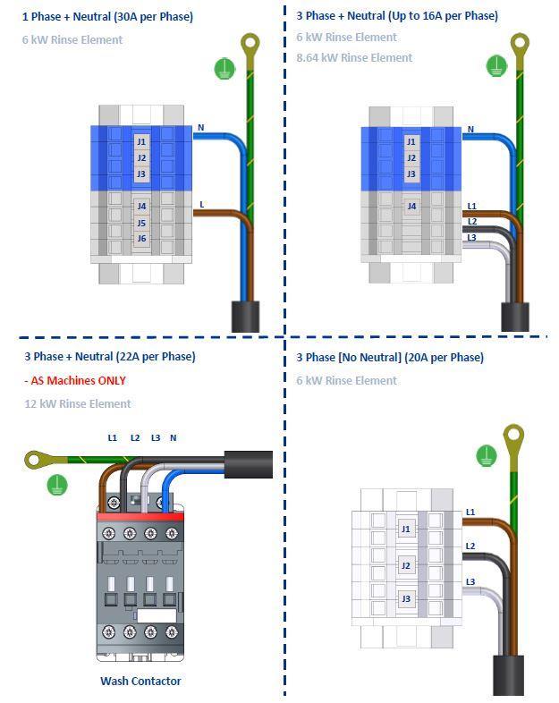
13 5.3.3 Terminal Block Layout 1) P500, P500A & P500A WS Terminal Block WASH Contactor RINSE Contactor 2) P500 AS & P500 AS WS Wash Contactor RINSE Contactor 1 RINSE Contactor 2 3) P500, P500A & P500A WS (No Neutral Machine) [60Hz] WASH Contactor RINSE Contactor Terminal Block Page 12
14 5.3.4 Contactors wiring 1) Machine - P500, P500A & P500 A WS A1 A2 1L1 3L2 5L3 COIL INPUT A1 & A2 (Black) From Control unit Output No 6 1L1 (Brown), 3L2 (Black) & 5L3 (Grey) From Terminal Block 2T1 4T2 6T3 OUTPUT 2T1 (Brown), 4T2 (Black) & 6T3 (Grey) To WASH ELEMENT WASH CONTACTOR A1 A2 1L1 3L2 5L3 COIL INPUT A1 & A2 (Black) From Control unit Output No 7 1L1 (Brown), 3L2 (Black) & 5L3 (Grey) From Terminal Block 2T1 4T2 6T3 OUTPUT 2T1 (Brown), 4T2 (Black) & 6T3 (Grey) To RINSE ELEMENT RINSE CONTACTOR Page 13
15 2) Machine - P500 AS & P500 AS WS A1 A2 COIL A1 & A2 (Black) From Control unit Output No 6 1L1 3L2 5L3 21NC INPUT 1L1 (Brown), 3L2 (Black) & 5L3 (Grey) From MAINS CABLE 1L1 (Brown), 3L2 (Black) & 5L3 (Grey) To RINSE CONTACTOR 1 (1L1, 3L2 & 5L3) 2T1 4T2 6T3 21NC (BLUE) From MAINS CABLE 21NC (BLUE) To MAINS FILTER WASH CONTACTOR OUTPUT 2T1 (Brown), 4T2 (Black) & 6T3 (Grey) To WASH SAFETY THERMOSTAT A1 A2 1L1 3L2 5L3 2T1 4T2 6T3 COIL INPUT OUTPUT A1 & A2 (PURPLE) From Control unit Output No 7 1L1 (Brown), 3L2 (Black) & 5L3 (Grey) From WASH CONTACTOR 1L1 (Brown), 3L2 (Black) & 5L3 (Grey) To RINSE CONTACTOR 2 (1L1, 3L2 & 5L3) 2T1 (Brown), 4T2 (Black) & 6T3 (Grey) To RINSE SAFETY THERMOSTAT 1 RINSE CONTACTOR 1 Page 14
16 A1 A2 COIL A1 & A2 (PURPLE) From Control unit Output No 7 1L1 3L2 5L3 INPUT 1L1 (Brown), 3L2 (Black) & 5L3 (Grey) From RINSE CONTACTOR 1 1L1 (Brown) To MAINS FILTER 2T1 4T2 6T3 OUTPUT 2T1 (Brown), 4T2 (Black) & 6T3 (Grey) To RINSE SAFETY THERMOSTAT 2 RINSE CONTACTOR 2 3) P500 & P500A No Neutral (60 hz) EXPORT Machine only A1 A2 1L1 3L2 5L3 COIL A1 & A2 (Black) From Control unit Output No 6 INPUT 1L1 (Brown), 3L2 (Black) & 5L3 (Grey) From Terminal Block 2T1 4T2 6T3 OUTPUT 2T1 (Brown), 4T2 (Black) & 6T3 (Grey) To WASH SAFETY THERMOSTAT WASH CONTACTOR Page 15
, 3L2 (Black) & 5L3 (Grey) From RINSE ELEMENT 2T1 4T2 6T3 OUTPUT 2T1 (Brown),")
 To RINSE SAFETY THERMOSTAT RINSE CONTACTOR 5.3.")
17 A1 A2 COIL A1 & A2 (Black) From Control unit Output No 7 1L1 3L2 5L3 INPUT 1L1 (Brown), 3L2 (Black) & 5L3 (Grey) From RINSE ELEMENT 2T1 4T2 6T3 OUTPUT 2T1 (Brown), 4T2 (Black) & 6T3 (Grey) To RINSE SAFETY THERMOSTAT RINSE CONTACTOR External Chemical Pumps connection ZSE OUTPUT 5 OUTPUT 3 RINSE AID DETERGENT T NEUTRAL EARTH Page 16
18 6. Logic 6.1Indicator logic 1 2 Item Description 1 Heating indicator 2 Cycle indicator Heating indicator This will illuminate GREEN only when following condition is achieved: Wash tank water level full Rinse tank water level full Refer ( 7.6.2) for more options. If one of these has not been achieved the indicator will flash AMBER to indicate that the machine has not achieved these Cycle indicator This will illuminate BLUE when a cycle has been requested. The cycle will then start when the above interlock requirements have been achieved. This will also flash BLUE during the drain process. In certain serious error conditions ( 7.6.5) this indicator will illuminate RED and the machine will turn off. Page 17
19 6.2Fill and heat Pressurised fill and heat Pressurised machines fill and rinse using the solenoid valve and site water pressure. These machines will fill in the following manner: 1) Activate solenoid valve until the wash air pressure sensor reads a minimum level. 2) Heat the rinse tank to a specified transfer temperature; this is lower than the rinse temperature to ensure that the wash tank is not too hot after the fill cycle. 3) Activate the solenoid valve to transfer water through the rinse tank to the wash tank for a specified time. 4) Repeat steps 1 to 3 until the wash tank is full. 5) Once wash tank water level is achieved, GREEN lamp should illuminate. 6) In the background machine will continue to heat until the rinse boiler and wash tank have both reached the specified temperatures. Below is a flow diagram to represent this. Page 18
20 6.2.2 Unpressurised fill and heat Unpressurised (air gap) machines fill and rinse using a rinse booster pump; this means that the rinse is not reliant on the incoming water pressure. These machines fill in the following manner: 1) Activate solenoid valve to fill rinse tank. 2) When rinse tank has reached the minimum level it will start to heat to a specified transfer temperature; this is lower than the rinse temperature to ensure that the wash tank is not too hot after the fill cycle. 3) Activate the rinse booster pump to transfer water for a specified time. 4) Repeat steps 1 to 3 until the wash tank is full. 5) Once the wash tank has reached a minimum level this will begin to heat if required while the rinse tank is refilling. 6) On machines with water softeners fitted the machine will calculate the volume of water that has passed through the unit and activate the regeneration process ( 6.6) as required. 7) Once wash tank water level and Rinse tank water level is achieved, GREEN lamp will illuminate. 8) In the background machine will continue to heat until the rinse boiler and wash tank have both reached the specified temperatures. Below is a flow diagram to represent this. Page 19
 Starts the wash cycle with wash pump activated. Soft start runs for first 6 seconds.")
21 6.3Wash and rinse If a cycle is requested when the machine is in standby the wash and rinse, process on all machines, follow the below procedure: 1) BLUE lamp is Illuminate on cycle indicator. 2) Starts the wash cycle with wash pump activated. Soft start runs for first 6 seconds. 3) Once the wash tank and rinse tank has achieved the interlock temperature (P41&P51) and the wash time has elapsed, Wash pump will be deactivated. If the interlock temperature are not satisfied during wash cycle time than it will extend the wash cycle till it has achieved it. 4) There is a pause of 8 seconds to allow the wash tank water to drip down back in wash tank. 5) Completes the rinse cycle for the specified time (P60) with activation and deactivation of Rinse pump. 6) There is a short pause after the rinse to allow water to drip down then the Cycle indicator will turn off. Below is a flow diagram to represent this. Refer ( 7.6.1) & ( 7.6.2) for more information on Parameters P41 & P51 and interlock options. Please note if condition for either P41 or P51 not met during specific wash cycle time than it will extend the wash cycle time till it satisfies the conditions. 6.4Drain The drain of the machine functions in two ways: 1. It monitors the water level in the wash tank and drains away any excess water at any time. 2. If the machine is turned off and the drain cycle is selected, this function will follow the below process: a. Start draining the machine. BLUE lamp flashes to indicate drain cycle. b. Once the water reaches the minimum level in the wash tank an Assisted clean function will transfer water from the rinse boiler in the same fashion as it fills ( 6.2) while continuing to drain (If the door is open at this time the Assisted clean will be cancelled). c. Once the wash tank reaches a minimum level again it activates a timer to drain out the remaining water. Page 20
22 Drain flow diagram to represent this. Page 21
23 6.5Chemical dosing The machine doses chemical at two different stages: 1. While filling the machine: a. The detergent is dosed into the wash tank with each transfer. At the end of the fill the rinse aid is dosed into the rinse tank. 2. While cycling the machine: a. When a cycle is selected the detergent will dose into the wash tank. This will not occur on the first cycle after filling the machine. b. After each cycle the rinse aid is dosed into the rinse boiler for the amount of water used. 6.6Water softener unit On machines with the integral water softener fitted the machine will monitor the amount of water passing through the resin of the softener unit and regenerate at intervals required by the water hardness setting ( 7.5.3). The regeneration process passes salt water into the resin, allows a contact period for the salt to scrub the resin then flushes this salt water out the waste. Re-fill salt indicator will flash to indicate water softener needs salt re-filling. Refer ( 3.3) for Salt specification and unit installation and operation manual for more information. Below is the timing for this function of the water softener unit. Function Rinse until resin exhausted Pause Salt to resin Pause Pressurise Regen (Contact) Pause Flush Pause Time 3s 25s 3s 1.5s 20s 3s 12s 3s ISV (O8) WS salt valve (O11) WS waste valve (O12) Page 22
 and Enter (2) buttons for 3sec.")

24 7. Commissioning/service modes 7.1Commissioning/service interface Item Description 1 Exit button 2 Enter button 3 Cycle indicator 4 Display 5 Up button 6 Down button 7.2Commissioning mode With the machine turned on at the mains electrical supply but off at the display, press and hold the Exit (1) and Enter (2) buttons for 3sec. the DISPLAY (4) will show the first menu item and the cycle indicator (3) will illuminate red. If no buttons have been pressed for a period of time the machine will cancel this mode and return to the off state. Below is the complete menu list. 6 3 Display Description Units r** Rinse aid setting (e.g. 15 = 1.5ml/L) 0.1 x ml/l rp0 Rinse aid prime 0 = Off 1 = On d** Detergent setting (e.g. 33 = 3.3ml/L) 0.1 x ml/l dp0 0 = Off Detergent prime 1 = On h** Water softener setting (if fitted) dh ** Refers to the setting of the chemical dosing. For example the default setting for rinse aid is 1ml of chemical per litre of water this will be displayed as r10 the default setting for detergent is 3ml of chemical per litre of water this will be displayed as d30 7.3Setting chemical dosage 1. Enter commissioning mode ( 7.2). 2. Using the UP and DOWN keys (5 & 6), scroll to the rinse aid setting menu item (r**) and Page 23
, scroll to the detergent setting menu item (d**) and press ENTER (2). 6. The display will flash. 7.")

25 press ENTER (2). 3. The display will flash. 4. Use the UP and DOWN keys (5 & 6) to scroll to the required setting and press ENTER (2). 5. Using the UP and DOWN keys (5 & 6), scroll to the detergent setting menu item (d**) and press ENTER (2). 6. The display will flash. 7. Use the UP and DOWN keys (5 & 6) to scroll to the required setting and press ENTER (2). 8. Press EXIT (1) until you are out of commissioning mode. 7.4Priming chemicals Before the machine can be used the chemical tubes will need to be filled with chemicals, in order to do this you will need to follow the below instructions to prime the chemical pumps. 1. Enter commissioning mode ( 7.2). 2. Using the UP and DOWN keys (5 & 6), scroll to the rinse aid prime menu item (rp0) and press ENTER (2) 3. The display will flash and will change to rp1. 4. This will continually run the rinse aid pump for a maximum of 12 minutes and draw chemicals into the machine. When the chemicals have reached the back of the machine press ENTER (2) again to stop the pump. 5. The display will stop flashing and return to rp0. 6. Using the UP and DOWN keys (5 & 6), scroll to the detergent prime menu item (dp0) and press ENTER (2) 7. The display will flash and will change to dp1. 8. This will continually run the detergent pump for a maximum of 2 minutes and draw chemicals into the machine. When the chemicals have reached the back of the machine press ENTER (2) again to stop the pump. 9. The display will stop flashing and return to dp Press EXIT (1) until you are out of commissioning mode. 7.5Integral water softener (if fitted) Commissioning the water softener unit To commission the water softener unit follow the instructions below: 1. Lift the hood up. 2. Remove the basket ramp. 3. Open the salt reservoir cap at the front right hand corner of the wash tank. 4. Fill the reservoir with fresh water. 5. Using the salt funnel supplied fill the reservoir with approximately 1.5kg of granulated salt. 6. Wipe away any excess or spilt salt from the cabinet and the reservoir opening. 7. Refit the cap to the reservoir, ensure that the cap is fitted flat and secure. Page 24
26 Warning Caution DO NOT run the machine if there is no salt in the salt reservoir, as this will allow lime scale to build up, also any lime scale will invalidate your warranty. DO NOT add any chemicals, such as detergent or rinse aid to the reservoir. These will cause damage to the machine. Only use granulated salt (max. grain size 5 7 mm). Salt tablets are not suitable. If the reservoir cap in not properly secured, water and/or chemicals can leak in or out of the unit causing damage to the machine Setting the water softener Check the water hardness of your water supply ( d). Once you have this data follow the steps below. 1. Refer to Appendix A to find the setting required for your water hardness ( 7.5.3). 2. Enter commissioning mode ( 7.2) 3. Using the UP and DOWN keys (5 & 6), scroll to the water hardness menu item (h**) and press ENTER (2). 4. The display will flash. 5. Use the UP and DOWN keys (5 & 6) to scroll to the setting you require and press ENTER (2). 6. Press EXIT (1) until you are out of commissioning mode Water softener settings Water softener setting dh e / clark fh ppm Water volume No of cycles h00 Deactivated h L 16 h L 15 h L 14 h L 14 h L 13 h L 12 h L 12 h L 11 h L 10 h L 10 h L 9 h L 9 h L 8 h L 7 h L 7 h L 7 h L 6 h L 6 h L 5 h L 5 h L 4 h L 4 h L 4 h L 3 h L 3 h L 3 h L 3 h L 2 h L 2 h L 2 Page 25
27 7.6Service mode With the machine turned on at the mains electrical supply but off at the display, press and hold the Exit (1) and Enter (2) buttons for 6sec. the DISPLAY (4) will show the first menu item and the cycle indicator (3) will illuminate red. If no buttons have been pressed for a period of time the machine will cancel this mode and return to the off state. Below is the complete menu list. Display P L E S Description Program values Loads Errors Statistics Program value The program values menu feeds back the reading that the sensors are receiving at the given time. Below is a list of the program values available. Below is a list of Programmes that can be activated, via the UP and DOWN keys (5 & 6). To select a particular programme press ENTER (2) Display Description Value P01 Display wash temperature *** P02 Display wash level *** P03 Display rinse temperature *** P04 Display rinse level *** P05 P06 P10 Display water flow rate (e.g. 40 = 4.0L/min) Display salt float switch status Display door switch status dl/min 0 = Full 1 = Empty 0 = Open 1 = Closed P30 Display model type **** P40 Wash tank target temperature C P41 Wash tank Interlock temperature C P50 Rinse tank target temperature C P51 Rinse tank Interlock temperature C P60 Rinse time Sec *** Refers to a value that will be displayed at the time of checking. **** Refers to a specific model number ( 8.2). P04 will display on pressurised machines. P05 and P06 will only display if an integral water softener is fitted. P40, P41, P50, P51 and P60 have predetermined upper and lower limits. CLASSEQ recommends the default values are maintained for correct operation of the machine. Page 26
28 7.6.2 Product Interlock settings Default machine setting is GREEN for faster recovery time. However if site required high hygienic and intense wash result then select the RED (Temperature based) option. During servicing the machine, if no Interlock is required then select the BLACK (No Interlock active) option. Please remember to change back to the default settings after servicing. Display P40 P41 P50 P51 Description Wash tank target temperature Wash tank Interlock temperature Rinse tank target temperature Rinse tank Interlock temperature GREEN (Default Setting) BLACK (No Interlock) RED (Full Interlock) ORANGE (Wash Interlock) 55 C 55 C 55 C 55 C 0 C 0 C 55 C 55 C 82 C 82 C 82 C 82 C 55 C 0 C 82 C 0 C Range P40 30 C to 75 C P41 30 C to P40 value C P50 55 C to 85 C P51 55 C to P50 value C Logic P41 P40 P51 P50 Note P41 P51 0 C = Wash Tank Interlock temperature OFF 0 C = Rinse Tank Interlock temperature OFF Re-set to Factory settings 1) Go to Parameter P30 (Display model type) and note down the Number. 2) Change to different number by scrolling UP and DOWN key (5 & 6). 3) Press ENTER (2) to select new P30 value. 4) Press EXIT (1) Button to come out of the service mode. 5) Go back to Parameter P30 and change the value back to noted Number on STEP 1. 6) Press ENTER (2) button to select the value. 7) Press EXIT (1) button to come out of the service mode. MACHINE BASE SETS P30 Model 100 P P500 A 102 P500 AS 103 P500 A WS 104 P500 AS WS Caution Any changes made to P30 will not be saved if power to the machine is disrupted before completely exiting service mode. Page 27
29 7.6.4 Loads The loads menu allows activation of specific loads within the machine in order to test their function. Some loads have safety criteria that need to be achieved before the load can be activated, if the component does not activate when the load is activated first check the continuity or resistance of the component through the harness. Below is a list of loads that can be activated, via the UP and DOWN keys (5 & 6), and their required criteria. Each of the loads has a safety timeout applied to reduce the risk of wear on the components. Display Description Value Safety criteria L00 Wash pump 0 = Off Wash water level above 1 = On minimum level and door closed. L01 Wash pump + soft start 0 = Off Wash water level above 1 = On minimum level and door closed. L02 L03 L04 L05 L06 L07 L08 L09 L11 L12 L13 Wash tank heat element Detergent pump Rinse pump Rinse aid pump Wash tank heat element - Spare Rinse tank heat element Inlet solenoid valve Drain pump WS Salt valve WS Waste valve WS Waste valve + inlet valve 0 = Off 1 = On 0 = Off 1 = On 0 = Off 1 = On 0 = Off 1 = On 0 = Off 1 = On 0 = Off 1 = On 0 = Off 1 = On 0 = Off 1 = On 0 = Off 1 = On 0 = Off 1 = On 0 = Off 1 = On L04 will display on pressurised machines. L11 and L12 will display if an integral water softener is fitted. Wash water level above minimum level. Wash water level above minimum level. Rinse water level above minimum level and door closed Errors The errors menu feeds back the last 40 errors on the machine in order to help identify the fault. Page 28
30 Use the UP (5) and DOWN (6) keys to cycle through the list, the list does not roll over and will always start on the most recent error. Below is a list of error codes and their possible cause. These are given as an aid only; all other possible causes of faults should be investigated before repair is carried out. Display Title Description Possible cause nnn New day Displays each time the machine is switched on. E01 E02 E03 E04 E05 E06 E07 E08 E09 E10 Wash tank pressure sensor Wash tank temperature sensor Rinse tank pressure sensor Rinse tank temperature sensor Wash water level unchanged during cycle. Rinse water level unchanged during rinse. Rinse tank temperature not achieved. Wash tank temperature not achieved. Wash water level unchanged during soft start. Salt missing Invalid signal from the wash pressure sensor. Invalid signal from the wash temperature sensor. Invalid signal from the rinse pressure sensor. Invalid signal from the rinse temperature sensor. Wash tank level not changed after soft start, repeated 3 times before error logged. Rinse tank level not changed when starting the rinse pump. Rinse tank has not reached the target temperature within 60 minutes. Wash tank has not reached the target temperature within 60 minutes. Wash tank level not changed during soft start. Only in machines with water softener fitted. Salt level in reservoir is low for 30 seconds. Page 29 Wash tank pressure sensor faulty or disconnected. Wash tank temperature sensor faulty. Rinse tank pressure sensor faulty or disconnected. Rinse tank temperature sensor faulty. Wash pump blocked. Wash arm blocked. Wash pump capacitor failed. Wash pump failed. Board output relay failed. Rinse arm blocked. Rinse pump blocked. Rinse pump capacitor failed. Rinse pump failed. Board output relay failed. Rinse tank over heat thermostat tripped. Rinse tank heating element failed. Rinse tank element contactor failed. Board output relay failed. Wash tank over heat thermostat tripped. Wash tank heating element failed. Board output relay failed. Wash pump blocked. Wash arm blocked. Wash pump capacitor failed. Wash pump failed. Board triac failed. No salt in reservoir. Salt reed switch failed.
31 E11 E12 E13 E14 E15 E16 E17 E18 E19 E20 Display communication failure Wash tank fill Rinse tank fill timeout Door switch Paddle flow sensor Wash tank overfill Filter mesh blocked Rinse tank temperature exceeded Wash tank temperature exceeded Power interruption No signal from the user interface unit. Wash tank has not filled within the required number of transfers. Rinse tank has not filled within 5 minutes. Door switch has not changed position for the past 20 cycles Only in machines with water softener fitted.paddle sensor in air gap is not responding during the fill stage. Wash tank has reached the flood risk level. Water level in wash tank has been reduced to below minimum required level during a wash cycle. Rinse tank temperature has exceeded the safety limit. Wash tank temperature has exceeded the safety limit. Power to machine has been interrupted. Page 30 User interface not correctly connected. User interface failed. Drain plug not inserted. Machine leaking. Very low water pressure (pressurised machines). Water supply not connected or turned on. Very low water pressure. Solenoid valve failed. Door switch failed. No water supply.paddle sensor failed.see P05 to assist. Site drain blocked. Machine waste hose blocked or kinked. Solenoid failed open. Drain pump failed. Wash arms blocked. Wash pump blocked. Wash filters blocked. Container in wash tank collecting water. Rinse tank temperature sensor disconnected. Rinse element relay fused. Main board relay fused. Rinse element wired incorrectly. Wash tank temperature sensor disconnected. Main board relay fused. Wash element wired incorrectly. Machine isolated from power supply. Power failure. E21 EEPROM Error EEPROM failed Main board failed E22 Invalid machine type Incorrect machine type set Machine type 0. Main board has not been configured. Items in BOLD will cause the machine to enter error mode; this will turn off the machine and illuminate the cycle indicator (3) red.
32 E12 Number of cycles will differ depending on machine. For E22 see Board setup ( 8.2) Statistics The statistics menu provides data on various aspects of the machine. Below is a list of the statistics that can be viewed. Display Description Units S00 Total number of completed wash cycles S01 Total run time (Power connected) Hours S02 Total active time (Machine ON) Hours S03 Total water usage Litres S04 Drain pump failures S20 Total number of regenerations S21 Total number of cycles without salt On gravity drain machines S04 may be regularly triggered. S20 and S21 are only active in machines with integral water softener fitted. Page 31
33 8. Control unit DANGER! Unless the machine has been isolated from the supply there will always be potential for mains voltage to any components in the machine. Repairs to the machine should only be done with the mains supply isolated. Caution 8.1Inputs and outputs Main board 4A 250V Fuse Label I1 I2 I3 I4 I5 I6 Bus Door PC LN Inputs Device Wash temperature sensor Wash pressure sensor Rinse temperature sensor Rinse pressure sensor Water softener float switch Water softener paddle wheel User interface Door reed switch Production test port Mains power from terminal block Page 32
34 Label O1 O2 O3 O4 O5 O6 O7 O8 O9 O10 O11 O12 O13 I/O Outputs Load Wash pump Not Used Rinse aid pump Rinse booster pump Detergent pump Wash contactor Rinse contactor Inlet solenoid valve Drain pump Not used WS board WS board Not used WS board power Water softener board Label WS I1 WS I/O Inputs Device Main board O11 and O12 Power from main board Label WS O1 WS O2 Outputs Load Water softener salt valve Water softener waste valve Page 33

35 8.2Board setup In the event of changing a control board the new board will need to be configured to the machine. The board will initially be set to Base set 0 and will give and error E22 and enter error mode if attempted to be turned on. In order to change the base set of the machine follow the instructions below: Step 1 Enter service mode ( 7.6). 2 Enter the Program values menu. 3 Instruction Scroll to P30 using the UP and DOWN (5 and 6) keys and enter. The DISPLAY (4) will start to flash. 4 Use the UP and DOWN keys (5 and 6) to select the correct base set for the machine. 5 Press ENTER to select (2). 6 Press EXIT (1) until completely out of the service mode. MACHINE BASE SETS P30 Model 100 P P500 A 102 P500 AS 103 P500 A WS 104 P500 AS WS Caution Any changes made to P30 will not be saved if power to the machine is disrupted before completely exiting service mode. Page 34
36 9. Cable Repair Kits 9.1Available Cable Kits list Detailed below are the spares cable kits available for the machine: Item Description Part number 1 KIT MACRO-MODULE PLUG SIZE 2,5 6-POLE KIT MACRO-MODULE PLUG SIZE 2,5 5-POLE KIT MACRO-MODULE PLUG SIZE 2,5 4-POLE KIT MACRO-MODULE PLUG SIZE 2,5 3-POLE KIT MACRO-MODULE PLUG SIZE 2,5 2-POLE Module Plug (Size 5,0 / 4Pole) Type A Module Plug (Size 5,0 / 4Pole) Type B Module Plug (Size 5,0 / 6Pole) ZSE Water Softener Harness Kit MACRO-MODULE PLUG5, 5-POLE Marco Module Plug5, 5Pole kW Element Wire Kit kW Element Wire Kit Cable Kit Information Items 1-11 are to be used to repair any damaged connections on the control harness connecting to the main ZSE board or the internal components. The kit consists of a replacement connector with a length of cable connected to a terminal block. This allows the damaged connector to be removed and replaced easily. A reference diagram is shown in section 9.3. Items are available to repair the heating circuit in situations where the element crimps or wires have been damaged. Included in these kits are a full set of wires from the terminal block to the element. Page 35
37 9.3 Cable Kit Diagram Page 36
38 10. Tool list The below list of tools will allow access to all components within the machine: Tool group Spanner/nut runner/ratchet Hex key Posi screw driver Electrical testing 5.5mm 7mm 8mm 13mm 2mm 3mm 4mm No. 2 No. 3 Description Ammeter (A) Capacitance meter (µf) Resistance meter (Ω) Continuity ( ) 11. Notes Page 37

39 12. Quick reference Page 38
40 13. Machine Rating Single Phase Three Phase RINSE ELEMENT 30A / V / 1N~ 50Hz 12A / V / 3N~ 50Hz 16A / V / 3N~ 50Hz 22A / V / 3N~ 50Hz 22A / V / 3~ 60Hz 6.0 kw ( ) 6 Legs YES YES NO NO NO 8.64 kw ( ) 6 Legs NO NO YES NO YES- But Only 6 kw Power 2 x 6.0 kw ( ) 6 Legs NO NO NO YES NO 13.1 Mains Cable Machine rating (Volts / Phase / Amps) Cable type V / 1N~/30A H07RN-f 3G V / 3N~/12A H07RN-f 5G V / 3N~/17A H07RN-f 5G V / 3N~/22A H07RN-f 5G V / 3~/17A H07RN-f 4G 2.5 Temp. rating Length of cable Conforms to 80 C min. 3m IEC & IEC types 56 & 57 Page 39
41 Page 40

42 14. Wiring Diagrams 1) _STD-WS Wiring Diagram P500, P500A & P500 A WS Page 41

43 2) _AS-WS Wiring diagram P500 AS & P500 AS WS Page 42
 Page")
44 3) _EXP-NN_Wiring_Diagram-P500 & P500A (110V/60Hz Machine only) Page 43
45 Document number: Revision: Rev C Date: 02/10/2018 Language: English Original instructions Page 44
Engineers manual. Pass Through machines P500 P500 A P500 AS P500 A WS P500 AS WS. A- AirBreak WS Water Softener. AS Dual Rinse Element
 P500 P500 A P500 AS P500 A WS P500 AS WS A- AirBreak WS Water Softener AS Dual Rinse Element Table of Contents 1. INTRODUCTION... 3 1.1 1.2 1.3 INSTALLATION AND COMMISSIONING... 3 SERVICE AND REPAIRS...
Engineers manual. Under counter machines
 Table of Contents 1. INTRODUCTION... 3 1.1 1.2 1.3 INSTALLATION AND COMMISSIONING... 3 SERVICE AND REPAIRS... 3 MODIFICATION... 3 2. EXPLANATION OF SYMBOLS USED... 3 3. WARNING AND SAFETY INFORMATION...
Installation and operation manual
 Installation and operation manual Under counter machines CAUTION: Read these instructions before operating the machine Accessories and Extras Detergents and Hygiene Products Application Product Name Quantity
The Classeq under counter range
 Installation & Operators Manual The under counter range Part number 902.0011 Revision C Effective date January 2010 Language English Glasswashers Eco 1 Eco 2 Eco 3 Duo 2 Duo 3 Dishwasher Hydro 500 Hydro
Installation and operation manual
 Installation and operation manual Under counter machines CAUTION: Read these instructions before operating the machine Accessories and Extras Detergents and Hygiene Products Application Product Name Quantity
Installation & Operators Manual. The Classeq Pass Through Range
 Installation & Operators Manual The Classeq Pass Through Range HYDRO 857 HYDRO 957 Service 0844 2245 245 service@classeq.co.uk Part number 902.0005 Revision E Jan 2012 Language English Spares 0844 2245
Installation & Operation Instructions. The Classeq pass through range
 Installation & Operation Instructions The Classeq pass through range Dishwashers HYDRO 857 HYDRO 957 HYDRO 957AS www.classeq.net Accessories and Extras Detergents and Hygiene Products Product Application
The Classeq pass Through range
 Installation & Operators Manual The Classeq pass Through range Part number 902.0005 Revision D July 2011 English HYDRO 857 HYDRO 957 Service Telephone 0844 2259245 Email : service@classeq.co.uk Spares
Installation & Operators Manual
 Installation & Operators Manual Eco, Hydro and Duo under counter range Part number 902.0011 Revision A Installation and Operation instructions For Classeq under counter range of glass and dishwashers.
Installation & Operators Manual
 Installation & Operators Manual Eco, Hydro and Duo under counter range Part number 902.0001 Revison B Installation and Operation instructions For Classeq under counter range of glass and dishwashers. Section
Service Engineers Manual (for software version ) Duo 2 Duo 3 Duo 500 Duo 750
 Duo 2 Duo 3 Duo 500 Duo 750") Service Engineers Manual (for software version 0.0.00) Duo Duo Duo 00 Duo 70 File location : Users on ClassicK\Works Print Folder\Under counter warewashers\double skin\duo\engineers manual Duo Service
Service Engineers Manual (for software version 0.0.00) Duo Duo Duo 00 Duo 70 File location : Users on ClassicK\Works Print Folder\Under counter warewashers\double skin\duo\engineers manual Duo Service
Digital Control Unit- Installation, Operation & Maintenance IMPORTANT INFORMATION
 Environment IMPORTANT INFORMATION It is not anticipated that this equipment will be exposed to adverse environmental conditions without additional protection. Site the equipment in a frost free area. Ensure
Glass and Dishwashers AMX / AUX Series
 Glass and Dishwashers AMX / AUX Series INSTALLATION OPERATION REV. 8.xx 04.07.2005 Installation and Operation Instructions for Models of AMX / AUX Series Content Page 1 Installation... 3 2 Connections...
Dishwasher technical manual
 07/2017 ENG Dishwasher technical manual UNIKO WI-FI 1 CONTENTS CONTENTS... 2 MEANING OF THE ICONS... 4 START-UP... 5 CONNECTION TO WI-FI 1.0... 7 Wi-Fi activation... 7 Dishwasher connection... 7 CONNECTION
MW001 Integrated Dishwasher. Manual for Installation, Use and Maintenance
 MW001 Integrated Dishwasher Manual for Installation, Use and Maintenance Important The CDA Group Ltd cannot be held responsible for injuries or losses caused by incorrect use or installation of this product.
AM900 / AMXX(T) / AUXX(T) / AUP SERIE
 / AUXX(T) / AUP SERIE") Service Manual HOBART GmbH An ITW-Company EFFICIENT RELIABLE INNOVATIVE AM900 / AMXX(T) / AUXX(T) / AUP SERIE AM900 / AMX(X) / AUXX / AUP SERIE STARTING FROM SERIAL NO. 8658 0001-8659 5999 EEPROM 897547-4
Service Manual HOBART GmbH An ITW-Company EFFICIENT RELIABLE INNOVATIVE AM900 / AMXX(T) / AUXX(T) / AUP SERIE AM900 / AMX(X) / AUXX / AUP SERIE STARTING FROM SERIAL NO. 8658 0001-8659 5999 EEPROM 897547-4
Installation, operating and servicing instructions
 English 57-115 - 144-1 - 259 Installation, operating and servicing instructions ITALIA EN 1 ITALIA English INDEX WARnINGS 3 Who should read these instructions 3 Symbols 3 Recommendations 3 Importants notes
The Professional s Choice
 SureFlow compact range: 1000-C & 1000-M Auto-Fill Catering Water Boiler Installation And User Instructions The Professional s Choice CONTENTS CONTENTS & INTRODUCTION 2 SAFETY & ENVIRONMENTAL INFORMATION
Technical Description: / Rev, Seq: H, 1 / Date: Remarks. At Customer error case. Blinking LED's at end of Flash process
 Technical Description: 56000000157007 / Rev, Seq: H, 1 / Date: 29.06.2010 Material No. 9000 361 479 Function Actuation Display Remarks Error class (failure group) In Customer Service program At Customer
What to expect from your water softener
 What to expect from your water softener All water softeners work on the same basic principal. Hard water flows through a bed of resin and the calcium and magnesium, the minerals that are responsible for
EDW500 / EDW503. Electronic Controls for Dishwashers
 EDW500 / EDW503 Electronic Controls for Dishwashers ESSE-N / A.S. October 2004 EDW500 - EDW503 EDW500 and EDW503: new entry level electronic controls for dishwashers in the DIVA family Intended to replace
User Manual. Dishwasher ZDM17301SA ZDM17301WA
 EN User Manual Dishwasher ZDM17301SA ZDM17301WA Contents Safety information 2 Safety instructions 3 Product description 4 Control panel 5 Programmes 6 Daily Use 7 Hints and tips 10 Care and cleaning 11
Technical Description: / Rev, Seq: F, 2 / Date: Remarks. At Customer error case. Blinking LED's at end of Flash process
 Technical Description: 56000000157007 / Rev, Seq: F, 2 / Date: 17.09.2009 Function Actuation Display Remarks Material No. 9000 361 479 Error class (failure group) In Customer Service program At Customer
FAVORIT 34502VI0. EN User manual
 FAVORIT 34502VI0 EN User manual 2 www.aeg.com CONTENTS 1. SAFETY INSTRUCTIONS...................................................... 3 2. PRODUCT DESCRIPTION.....................................................
wc431 Slimline Integrated Dishwasher Manual for Installation, Use and Maintenance
 wc431 Slimline Integrated Dishwasher Manual for Installation, Use and Maintenance Contents Contents... 2 Important... 3 Important Notes... 4 Recommendations... 5 Before First Use... 5 Control Panel...
BEFORE USING THE DISHWASHER/CONNECTIONS
 INSTRUCTIONS FOR USE BEFORE USING THE DISHWASHER/CONNECTIONS ELECTRICAL CONNECTION PRECAUTIONS AND GENERAL RECOMMENDATIONS HOW TO FILL THE SALT CONTAINER HOW TO FILL THE RINSE AID DISPENSER HOW TO FILL
FAVORIT34502VIO. EN User Manual
 FAVORIT34502VIO EN User Manual 2 www.aeg.com CONTENTS 1. SAFETY INFORMATION...3 2. SAFETY INSTRUCTIONS... 4 3. PRODUCT DESCRIPTION... 6 4. CONTROL PANEL...6 5. PROGRAMMES... 7 6. SETTINGS... 8 7. BEFORE
Glass and Dishwashers AMX / AUX Series
 Glass and Dishwashers AMX / AUX Series INSTALLATION OPERATION VERSION 24.02.04 Important Notes Use in Accordance with Regulations This machine is exclusively to be used to wash ware such as plates, cups,
Glass and Dishwashers. BarAid 500/800. Installation and. Starting from Serial No.:
 Glass and Dishwashers BarAid 500/800 Installation and operation Instructions Starting from Serial No.: 8652 0001 REV. 19.01.2009 1617-A-01-09 Content Page 1 Important Notes... 4 2 Installation... 5 2.1
FAVORIT W0P. EN User manual
 FAVORIT 88419 W0P EN User manual 2 www.aeg.com CONTENTS 1. SAFETY INSTRUCTIONS...................................................... 3 2. PRODUCT DESCRIPTION.....................................................
User manual. Dishwasher ZDI12001
 EN User manual Dishwasher ZDI12001 Contents Safety information 2 Product description _ 3 Control panel 3 Programmes 4 Before first use _ 4 Daily use 7 Care and cleaning 9 Troubleshooting 9 Technical information
MODEL CMA-180UC INSTALLATION & OPERATION Rev 1.17A
 Owner s Manual MODEL CMA-180UC INSTALLATION & OPERATION Rev 1.17A C M A D I S H M A C H I N E S 1 2 7 0 0 K N O T T S T R E E T GARDEN GROVE, CALIFORNIA 92841 800-8 5 4-6 4 1 7 FAX 714-895-2141 www.cmadishmachines.com
AQUARIUS 45 MARINE SERVICE MANUAL
 AQUARIUS 45 MARINE SERVICE MANUAL CONTENTS: PAGE 1. INTRODUCTION 3 2. SAFETY INSTRUCTIONS 4 3. BASIC INSTRUCTIONS 5 3.1. Installation Details 5 3.2. Operating the Boiler for the First Time 6 3.3. Troubleshooting
MW401 Integrated Dishwasher
 MW401 Integrated Dishwasher Manual for Installation, Use and Maintenance Customer Care Department The Group Ltd. Harby Road Langar Nottinghamshire NG13 9HY T : 01949 862 012 F : 01949 862 003 E : service@cda.eu
MW402 Integrated Dishwasher
 MW402 Integrated Dishwasher Manual for Installation, Use and Maintenance 1 Customer Care Department The Group Ltd. Harby Road Langar Nottinghamshire NG13 9HY T : 01949 862 012 F : 01949 862 003 E : customer.care@cda.eu
Flopurge TS. Operation Manual
 Flopurge TS Operation Manual Part Number 079-0204 Spectron Gas Control Systems United Kingdom Unit 4, Herald Court, University of Warwick Science Park, Coventry, CV4 7EZ +44 (0)24 7641 6234 sales@spectron-gcs.com
HX-30/40 and HX-30/40 S Glass and Dishwashers
 HX-30/40 and HX-30/40 S Glass and Dishwashers INSTALLATION OPERATION VERSION 18/01/00 2 Installation and Operation Instructions for Model HX-30/40 and HX-30/40 S (with built-in softener) Content Page 1
ECOMAX 602/612/AM-10/AM-11
 Service Manual HOBART GmbH An ITW-Company EFFICIENT RELIABLE INNOVATIVE ECOMAX 402/452/502 Start Serial No.: 8663 000 8663 3999 EEPROM: 897547-6 Facelift as of Serial No.: 8663 4000 EEPROM: 897547-7 ECOMAX
User manual. Dishwasher ZDT15002
 EN User manual Dishwasher ZDT15002 Contents Safety information 2 Product description _ 3 Control panel 4 Programmes 4 Options _ 5 Before first use _ 5 Daily use 7 Care and cleaning 9 Troubleshooting 10
Service Parts
 GM Operator Manual !!!! WARNING Before installation and commisioning, you must read the safety instructions and warnings carefully and all the warning labels attached to the equipment. IMPORTANT Failure
User manual. Dishwasher ZDT12041FA
 EN User manual Dishwasher ZDT12041FA Contents Safety instructions 2 Control panel 3 Programmes _ 4 Options _ 4 Before first use _ 5 Daily use _ 7 Hints and tips 9 Care and cleaning 9 Troubleshooting 10
INSTALLATION MANUAL GUTHD2. Universal Two Way Digital Thermostatic Valve for Shower Systems
 INSTALLATION MANUAL GUTHD2 Universal Two Way Digital Thermostatic Valve for Shower Systems IMPORTANT: To ensure this product is installed properly, you must read and follow these guidelines. The owner/
D3000. Installation & Setup Guide
 Page 1 of 15 17483-00 Rev B s1 April 2009 Contents Description Page Safety... 3 Installation Standards 3 Specification. 3-4 Circuit Board Connection 5 Mounting Dimensions 6 Installation Procedure 6 Mechanical
Glass and Dishwashers 402/452/502. (original instructions) (incl. Australian /502) Starting from Serial No.:
 (incl. Australian /502) Starting from Serial No.:") Glass and Dishwashers ECOMAX 402/452/502 (incl. Australian 452-90/502) INSTALLATION AND OPERATION INSTRUCTIONS (original instructions) Starting from Serial No.: 8663 4000 REV. 05.10.2015 EN IMPORTANT NOTES
Glass and Dishwashers ECOMAX 402/452/502 (incl. Australian 452-90/502) INSTALLATION AND OPERATION INSTRUCTIONS (original instructions) Starting from Serial No.: 8663 4000 REV. 05.10.2015 EN IMPORTANT NOTES
WC141 Integrated Dishwasher Installation, Use and Maintenance
 WC141 Integrated Dishwasher Installation, Use and Maintenance Customer Care Department The Group Ltd. Harby Road Langar Nottinghamshire NG13 9HY T : 01949 862 012 F : 01949 862 003 E : customer.care@cda.eu
POTWASHER WD-12. Installation and user manual
 POTWASHER WD-12 (translation of the original documentation) Installation and user manual S/N: Valid from: 01. 04. 2011 Rev.: Dear Customer, Congratulations on deciding to choose a Metos appliance for your
FAVORIT W0P. EN User manual
 FAVORIT 77000 W0P EN User manual 2 www.aeg.com CONTENTS 1. SAFETY INSTRUCTIONS...................................................... 3 2. PRODUCT DESCRIPTION.....................................................
Flostop TS D7E and A8E. Operation Manual
 Flostop TS D7E and A8E Operation Manual United Kingdom Spectron Gas Control Systems Ltd, Unit 4, ATU1, University of Warwick science Park, Coventry, +44 (0) 24 7641 6234 sales@spectron-gcs.com Germany
User manual. Dishwasher ZDT15010FA
 EN User manual Dishwasher ZDT15010FA Contents Safety instructions 2 Control panel 3 Programmes _ 4 Options _ 5 Before first use _ 6 Daily use _ 7 Hints and tips 9 Care and cleaning _ 10 Troubleshooting
11/2012. Mod: D281/EKA-NP. Production code:
 11/2012 Mod: D281/EKA-NP Production code: 916658 INSTRUCTION MANUAL FOR DISHWASHERS UK CONTENTS CHAP 1 PREFACE... 2 CHAP 2 INSTALLATION... 2 2.1 UNPACKING... 2 2.2 POSITIONING... 3 2.3 ELECTRICAL CONNECTION...
The Professional s Choice
 CPF Series Models: CPF2100, CPF210, CPF310, CPF4100-3, CPF4100-6 & CPF6100 Auto-Fill Catering Water Boiler With Integrated Multi-Filter Installation And User Instructions The Professional s Choice INSTANTA
FAVORIT DISHWASHER USER MANUAL
 FAVORIT 77000 DISHWASHER USER MANUAL 2 CONTENTS 4 SAFETY INFORMATION 6 PRODUCT DESCRIPTION 7 CONTROL PANEL 8 PROGRAMMES 10 OPTIONS 11 BEFORE FIRST USE 14 DAILY USE 17 CARE AND CLEANING 18 TROUBLESHOOTING
REPAIR PART DIAGRAMS. Pages: 1-6
 REPAIR PART DIAGRAMS PRODUCT: MODEL: DISHWASHER LL S The information included in this Ariston Spare Parts List may change without notice please see our web site www.usservicenet.com for updates, corrections
Installation and operating instructions. Temperature difference controller 6 inputs, 3 outputs, integrated data logger for SD card
 SOLARTHERMIE - SOLAR THERMAL - SOLAR TÉRMICO - SOLAIRE THERMIQUE - SOLARE TERMICO Installation and operating instructions Temperature difference controller 6 inputs, 3 outputs, integrated data logger for
User manual. Dishwasher ZDI12010XA
 EN User manual Dishwasher ZDI12010XA Contents Safety instructions 2 Control panel 4 Programmes _ 4 Before first use _ 5 Daily use _ 7 Hints and tips 9 Care and cleaning 9 Troubleshooting 10 Technical information
All spares available from. System-Matic Ltd
 All spares available from System-Matic Ltd 0844 272 0556 Copyright Notice: All rights reserved. No parts of this manual may be reproduced in any form without express written permission of Maidaid-Halcyon
COMPONENTS AND FUNCTIONALITY
 COMPONENTS AND FUNCTIONALITY ESSE-N / A.S. 1 Common Circulation Pumps DIVA ZM+DGN 2 suppliers (FHP - Sole) fully interchangeable same performances versions: with / without tachymetric generator with /
Installation & User Guide
 Installation & User Guide All spares available from The Engine Shed Top Station Road Brackley NN13 7UG Tel: 0845 1308060 Fax: 01280 845345 Web: www.caterparts.com Copyright Notice: All rights reserved.
BarAid 400. Installation and. Starting from Serial No.:
 Glasswasher BarAid 400 Installation and operation Instructions Starting from Serial No.: 8649 1065 REV. 19.01.2009 DE 1618-A-01-09 Content Page 1 Important Notes... 4 2 Installation... 5 2.1 Location...
WC370 Integrated Intelligent dishwasher Manual for Installation, Use and Maintenance
 WC370 Integrated Intelligent dishwasher Manual for Installation, Use and Maintenance Customer Care Department The Group Ltd. Harby Road Langar Nottinghamshire NG13 9HY T : 01949 862 012 F : 01949 862 003
FAVORIT VI DISHWASHER USER MANUAL
 FAVORIT 55002 VI DISHWASHER USER MANUAL 2 CONTENTS 4 SAFETY INFORMATION 6 PRODUCT DESCRIPTION 7 CONTROL PANEL 8 PROGRAMMES 9 OPTIONS 10 BEFORE FIRST USE 13 DAILY USE 16 CARE AND CLEANING 17 TROUBLESHOOTING
WC600 Integrated Dishwasher Installation, Use and Maintenance
 WC600 Integrated Dishwasher Installation, Use and Maintenance Customer Care Department The Group Ltd. Harby Road Langar Nottinghamshire NG13 9HY T : 01949 862 012 F : 01949 862 003 E : customer.care@cda.eu
GETTING STARTED? EASY.
 User Manual GETTING STARTED? EASY. ZDF26001WA ZDF26001XA EN User Manual Dishwasher SAFETY INFORMATION Before the installation and use of the appliance, carefully read the supplied instructions. The manufacturer
Manual for installation, use and maintenance MW402. Integrated Dishwasher. year. parts + 1 year labour guarantee.
 Manual for installation, use and maintenance MW402 Integrated Dishwasher year parts + 1 year labour guarantee www.matrixappliances.co.uk Contents: 3 Important information 5 Important notes 5 Recommendations
Spare parts list GS GS GS 315
 Spare parts list GS 0 - GS - GS Contents Water inlet Page Water softener GS 0, GS Page Water drain, Mediamat Cyclo Page Wash pump Page Bottom washing/rinsing system Page Top washing/rinsing system Page
FAVORIT 66609M0P FAVORIT 66609W0P. EN User Manual
 FAVORIT 66609M0P FAVORIT 66609W0P EN User Manual 2 www.aeg.com CONTENTS 1. SAFETY INFORMATION...3 2. SAFETY INSTRUCTIONS... 4 3. PRODUCT DESCRIPTION... 5 4. CONTROL PANEL...6 5. PROGRAMMES... 7 6. SETTINGS...
Owner s Manual. Keep with machine for reference CMA DISHMACHINES KNOTT AVENUE GARDEN GROVE, CALIFORNIA FAX
 Owner s Manual Keep with machine for reference MODELS CMA-180/180 TALL Including 480V MACHINES Installation and Operation Rev 2.08 CMA DISHMACHINES 12700 KNOTT AVENUE GARDEN GROVE, CALIFORNIA 92841 800-854-
TOTAL SOLUTIONS. Liquid Level Control Product Guide. MATELEC AUSTRALIA innovative by design
 TOTAL SOLUTIONS Liquid Level Control Product Guide MATELEC innovative by design Liquid Level Control Contents Dual Pump Controllers Section 1 The Range Common Features Operating Data Control Logic Setup
user manual Dishwasher ESL 46510
 user manual Dishwasher ESL 46510 2 electrolux CONTENTS Electrolux. Thinking of you. Share more of our thinking at www.electrolux.com Safety information 2 Product description 5 Control panel 5 Use of the
User manual. Dishwasher ZDF14001WA ZDF14001KA ZDF14001SA
 EN User manual Dishwasher ZDF14001WA ZDF14001KA ZDF14001SA Contents Safety instructions 2 Control panel 4 Programmes _ 4 Options _ 5 Before first use _ 6 Daily use _ 7 Hints and tips 9 Care and cleaning
3. Before switching the equipment on, make sure that the model plate data conforms to that of the electrical and water distribution network.
 Manuale di istruzione per lavastoviglie Notice d utilisation pour lave-vaisselle Gebrauchsanweisung für Geschirrspüler Instruction manual for dishwashers Manual de instrucciones para lavavajillas LF315
Winterhalter under counter dishwashing machines UC series. Operating instructions
 Winterhalter under counter dishwashing machines UC series Operating instructions Short instructions IMPORTANT: Read the detailed operating instructions and safety notes before first use. Switching on the
Product Manual. Viscount IV series of carbonators and chillers. Part Number 3B3075 Issue 01 [ ]
![Product Manual. Viscount IV series of carbonators and chillers. Part Number 3B3075 Issue 01 [ ]](/thumbs/89/99049177.jpg "Product Manual. Viscount IV series of carbonators and chillers. Part Number 3B3075 Issue 01 [ ]") Product Manual Viscount IV series of carbonators and chillers Part Number 3B3075 Issue 01 [16-04-07] Contents Section Page Section Page Introduction 2 Safety 2 Description 2 Schematics 4 Fault Finding
Product Manual Viscount IV series of carbonators and chillers Part Number 3B3075 Issue 01 [16-04-07] Contents Section Page Section Page Introduction 2 Safety 2 Description 2 Schematics 4 Fault Finding
Servicing manual. Wall-mounted condensing gas boiler 600 Series - 11S / 19S / 24S / 24C /2002 GB(EN) For trade use
 For trade use") GB122 7210 1300-12/2002 GB(EN) For trade use Servicing manual Wall-mounted condensing gas boiler 600 Series - 11S / 19S / 24S / 24C Please read thoroughly before attempting to diagnose fault List of contents
GB122 7210 1300-12/2002 GB(EN) For trade use Servicing manual Wall-mounted condensing gas boiler 600 Series - 11S / 19S / 24S / 24C Please read thoroughly before attempting to diagnose fault List of contents
Service Manual - Series 450/451 IG IGV IG IGV IG IG IG IGV IG
 Service Manual - Series 450/451 IG 448... IGV 449... IG 458... IGV 459... IG 459... IG 4408.0 IG 4406.0 IGV 4408.0 IG 4408.1 Service Manual: H7-71-04 Responsible: Dieter Rutz KÜPPERSBUSCH HAUSGERÄTE AG
WF140 Freestanding Dishwasher
 WF140 Freestanding Dishwasher Installation, Use and Maintenance Customer Care Department The Group Ltd. Harby Road Langar Nottinghamshire NG13 9HY T : 01949 862 012 F : 01949 862 003 E : customer.care@cda.eu
SERVICE MANUAL AMX(X) / AUXX / AUP SERIES. Service Manual. Starting from Serial no HOBART GmbH An ITW-Company SERVICE TRAINING CENTER
 / AUXX / AUP SERIES. Service Manual. Starting from Serial no HOBART GmbH An ITW-Company SERVICE TRAINING CENTER") Service Manual HOBART GmbH An ITW-Company EFFICIENT RELIABLE INNOVATIVE SERVICE MANUAL AMX(X) / AUXX / AUP SERIES Starting from Serial no 8658 0001 This document is produced for internal use only. The
Service Manual HOBART GmbH An ITW-Company EFFICIENT RELIABLE INNOVATIVE SERVICE MANUAL AMX(X) / AUXX / AUP SERIES Starting from Serial no 8658 0001 This document is produced for internal use only. The
Owner s Manual. Sovereign Mark 5. Glass Washing Machine. WEE/DE2076RU Machines are manufactured to ISO 9001 : 2008
 Owner s Manual Sovereign Mark 5 Glass Washing Machine WEE/DE2076RU Machines are manufactured to ISO 9001 : 2008 Index Sovereign Glass Washer Operating Instructions... 3 Preparation... 3 Filling... 4 Standby
Installation, Operating and Servicing Instructions
 Installation, Operating and Servicing Instructions Wall Mounted Water Boiler WMB3F/B,WMB3F/W Please make a note of your product details for future use: Date Purchased: Model Number: Serial Number: Dealer:
aáëüï~ëüéê=ëéêáéë=bat=nrmp cìååíáçå~äáíáéë
 aáëüï~ëüéê=ëéêáéë=bat=nrmp cìååíáçå~äáíáéë Service Manual: H7-74-03D Product identification Code for the production numbers used for the various models (PNC) F.S. - Free-standing B. I. - Partially integrated
Service Manual W365H, W375H, W3105H, W3130H, W3180H, W3240H, W3300H Wascator FOM71 CLS Clarus Control
 Service W365H, W375H, W3105H, W3130H, W3180H, W3240H, W3300H Wascator FOM71 CLS Clarus Control 438 9201-51/EN 06.42 Overview Safety precautions Technical data Machine presentation Programmes 1 2 3 4 5
MIKE 2 Modular control system
 MIKE 2 Modular control system 1. Simplified construction of the GK machine Fresh water Frischwasserzuleitung supply pipe Rinse aid Rinse aid Detergent Detergent door closed container Klarspüler Behälter
FLOW CONTROLLER TYPE S/601
 Checked Version Release date QA V4.2.6 F1 F2 EN 26.01.2012 Manual FLOW CONTROL FLOW CONTROLLER TYPE S/601 MODELS F1 AND F2 INTRODUCTION Thank you for using the S/601 flow and batch control series. This
Manual for installation, use and maintenance MW200. Integrated Slimline Dishwasher. year. parts + 1 year labour guarantee.
 Manual for installation, use and maintenance MW200 Integrated Slimline Dishwasher year parts + 1 year labour guarantee www.matrixappliances.co.uk Contents: 3 Important information 5 Important notes 6 Recommendations
INSTALLATION & TECHNICAL MANUAL
 The COMET Range of Boilers the ultimate solution for central heating INSTALLATION & TECHNICAL MANUAL If you require any further assistance: Telephone: 01698 820533 Fax: 01698 825697 E-mail: info@electric-heatingcompany.co.uk
Slimline Dishwasher Instruction Manual
 Slimline Dishwasher Instruction Manual Model Number: RHSLDW1 Please read these instructions carefully and keep them for future reference For Customer Services, Spare Parts & Manufacturer s Warranty Information,
Marco Beverage Systems Ltd. INSTRUCTIONS FOR MODELS
 Marco Beverage Systems Ltd. INSTRUCTIONS FOR MODELS Ecoboiler UC4L 2.4kW (1000740#) Ecoboiler UC10L 2.8kW (1000741#) Ecoboiler UC10L 5.6kW (1000742#) Ecoboiler UC4L 1.5kW 110V (1000747) Ecosmart UC4L 2.4kW
Janfire Pellet Burner Boiler. for single / double burner management (Version 1.1)
") SY325 Janfire Pellet Burner Boiler for single / double burner management (Version 1.1) TECHNICAL DATA SHEET V1.1 rev.12/2007 Contents INTRODUCTION...3 1 THE CONTROL PANEL...4 2 THE KEYS...4 3 THE LEDS...4
SY325 Janfire Pellet Burner Boiler for single / double burner management (Version 1.1) TECHNICAL DATA SHEET V1.1 rev.12/2007 Contents INTRODUCTION...3 1 THE CONTROL PANEL...4 2 THE KEYS...4 3 THE LEDS...4
ESL 5201LO EN DISHWASHER USER MANUAL
 ESL 5201LO EN DISHWASHER USER MANUAL 2 www.electrolux.com CONTENTS 1. SAFETY INFORMATION... 2 2. SAFETY INSTRUCTIONS...4 3. PRODUCT DESCRIPTION... 5 4. CONTROL PANEL...6 5. PROGRAMMES...6 6. SETTINGS...
Operating instructions
 Operating instructions for Winterhalter Gastronom dishwasher GS 502 and GS 515 Contents Page 1 Intended use... 1 2 Installation and commissioning... 1 3 Safety instructions... 2 4 Operating panel... 3
Water Softener Installation Guide Effective for all Softeners from our Range
 Water Softener Installation Guide Effective for all Softeners from our Range Planning Your Installation Always observe the water byelaws. Ensure there is only one rising main, that you have allowed space
FHHT 18 3 PHASE /32A / 400V ELECTRIC HEATER PRODUCT MANUAL P
 FHHT 18 3 PHASE /32A / 400V ELECTRIC HEATER PRODUCT MANUAL P 1 of 13 These instructions should be read by: The specifying engineer. The installation engineer. The user. The service engineer. WARNINGS Failure
Slimline Dishwasher. Instruction Manual
 Slimline Dishwasher Instruction Manual Model number: RHSLDW1 (B) (S) (G) Opening times: Monday - Friday 8am 6pm & Saturday 9am 1pm or visit us at www.productcareuk.com Contents Safety Instructions 3-4
Installation manual Washer extractor
 Installation manual Washer extractor W555H Type W.55.H Original instructions 438 9054-30/EN 2017.11.06 Contents Contents 1 Safety Precautions...5 1.1 General safety information...6 1.2 Commercial use
INSTRUCTIONS MANUAL CONTROLS. Description Power Rating Remarks Steamer. Description Power Rating Remarks Control
 Description Power Rating Remarks Control Rated Power 3 Phases Rated Voltage 3 Phases Rated Power Single Phase Rated Voltage Single Phase Frequency Switching capacity per phase Sauna temperature range Maximum
GETTING STARTED? EASY.
 User Manual GETTING STARTED? EASY. ZDT21006FA EN User Manual Dishwasher SAFETY INFORMATION Before the installation and use of the appliance, carefully read the supplied instructions. The manufacturer is
Forced draught gas burner
 Installation, use and maintenance instructions Forced draught gas burner Code Model Type 3751982 GAS 3 519T80 291 (3) - 02/2010 DECLARATION Declaration of conformity in accordance with ISO / IEC 17050-1
SERVICE MANUAL. Marco Beverage Systems Ltd. 63d Heather Road, Sandyford Industrial Estate, Dublin 18, Republic of Ireland
 SERVICE MANUAL Under Counter Range, Model UC45 1000743 (2.8kW) 1000744 (5.6kW) 1000744US (5.6kW) 1000745 (8.4kW) 1000753 (2.8kW) 1000754 (5.6kW) 1000755 (8.4kW) 1000743A (2.8kW) 1000744A (5.6kW) 1000745A
User Manual Dishwasher FAVORIT 66602VI0P
 EN User Manual Dishwasher FAVORIT 66602VI0P 2 www.aeg.com CONTENTS 1. SAFETY INFORMATION...3 2. SAFETY INSTRUCTIONS... 4 3. PRODUCT DESCRIPTION... 5 4. CONTROL PANEL...6 5. PROGRAMMES... 7 6. SETTINGS...
OPERATION MANUAL RK-2006LPP AUGER FITTED SOLID FUEL BOILER TEMPERATURE CONTROLLER. Version DC19
 OPERATION MANUAL RK-2006LPP AUGER FITTED SOLID FUEL BOILER TEMPERATURE CONTROLLER Version DC19 1. Application. Controller RK-2006LPP is designed for temperature control of solid fuel fired water boilers