I International Bureau (10) International Publication Number (43) International Publication Date
|
|
|
- Samson Johns
- 5 years ago
- Views:
Transcription
1 (12) INTERNATIONAL APPLICATION PUBLISHED UNDER THE PATENT COOPERATION TREATY (PCT) (19) World Intellectual Property Organization I International Bureau (10) International Publication Number (43) International Publication Date WO 2013/ Al 10 January 2013 ( ) P O P C T (51) International Patent Classification: (74) Agent: ZACCO NORWAY AS; P.O. Box 2003 Vika, N- F28D 1/06 ( ) F28F 27/00 ( ) 0125 Oslo (NO). F28D 7/02 ( ) E21B 36/00 ( ) (81) Designated States (unless otherwise indicated, for every F28D 15/00 ( ) kind of national protection available): AE, AG, AL, AM, (21) International Application Number: AO, AT, AU, AZ, BA, BB, BG, BH, BR, BW, BY, BZ, PCT/EP201 1/ CA, CH, CL, CN, CO, CR, CU, CZ, DE, DK, DM, DO, DZ, EC, EE, EG, ES, FI, GB, GD, GE, GH, GM, GT, HN, (22) International Filing Date: HR, HU, ID, IL, IN, IS, JP, KE, KG, KM, KN, KP, KR, 1 July ( ) KZ, LA, LC, LK, LR, LS, LT, LU, LY, MA, MD, ME, (25) Filing Language: English MG, MK, MN, MW, MX, MY, MZ, NA, NG, NI, NO, NZ, OM, PE, PG, PH, PL, PT, RO, RS, RU, SC, SD, SE, SG, (26) Publication Language: English SK, SL, SM, ST, SV, SY, TH, TJ, TM, TN, TR, TT, TZ, (71) Applicant (for all designated States except US): UA, UG, US, UZ, VC, VN, ZA, ZM, ZW. STATOIL PETROLEUM AS [NO/NO]; N-4035 (84) Designated States (unless otherwise indicated, for every Stavanger (NO). kind of regional protection available): ARIPO (BW, GH, (72) Inventors; and GM, KE, LR, LS, MW, MZ, NA, SD, SL, SZ, TZ, UG, (75) Inventors/Applicants (for US only): KAASA, Baard ZM, ZW), Eurasian (AM, AZ, BY, KG, KZ, MD, RU, TJ, [NO/NO]; Nordlivegen 8E, N-7053 Ranheim (NO). TM), European (AL, AT, BE, BG, CH, CY, CZ, DE, DK, RUSTEN, Bernt Henning [NO/NO]; L0nnvegen 33, N- EE, ES, FI, FR, GB, GR, HR, HU, IE, IS, IT, LT, LU, LV, 7059 Jakobsli (NO). FREDHEIM, Arne Olav [NO/NO]; Tingveien 21C, N-7046 Trondheim (NO). MARAK, Knut Arild [NO/NO]; Frostaveien 9B, N-7043 Trondheim (NO). SKOFTELAND, Gunleiv [NO/NO]; Granaslia 9, N-7047 Trondheim (NO). MC, MK, MT, NL, NO, PL, PT, RO, RS, SE, SI, SK, SM, TR), OAPI (BF, BJ, CF, CG, CI, CM, GA, GN, GQ, GW, ML, MR, NE, SN, TD, TG). Published: with international search report (Art. 21(3)) (54) Title: SUBSEA HEAT EXCHANGER AND METHOD FOR TEMPERATURE CONTROL l o o o (57) Abstract: The invention concerns a subsea heat exchanger for cooling or heating a hydrocarbon-containing fluid, said heat ex - changer comprising: a convection section enclosed by a shell or enclosure comprising: one or more heat exchanging fluid inlet(s) and outlet(s); one or more hydrocarbon-containing fluid inlet(s) and outlet(s); and one or more fluid carrying convection tube(s) ad apted for heat transfer between the hydrocarbon-containing fluid on the inside of the tube(s) and a surrounding heat exchanging fluid on the opposite side of the tube(s),wherein the heat exchanger is provided with one or more flow regulating device(s) for controlling the hydrocarbon- containing fluid outlet temperature, wherein the heat exchanging fluid circulates in a closed circuit for heat transfer both with said hydrocarbon-containing fluid and with surrounding sea water on the outside of the enclosure. The invention also con cerns a method for subsea cooling or heating of a hydrocarbon containing fluid.
2 Subsea heat exchanger and method for temperature control Field of the invention The invention relates to a subsea heat exchanger unit with output temperature control, and especially a convection heat exchanger for the cooling or heating of a produced hydrocarbon containing fluid stream, such as from one or more subsea wells, and methods for such temperature control. Background The temperature of a produced hydrocarbon containing stream at subsea level is generally hot and may normally vary in temperatures in the range of at the prevailing pressures. In order to process or transport such a hot hydrocarbon fluid stream, it may be necessary to regulate the temperature of the stream, such as by cooling the stream to a specific temperature, e.g. in the range of 0-60 C. A number of existing oil coolers located on the seabed are not controllable and have the limitation of only cooling the oil from a well stream after separation of gas the phase. Such coolers are used to reduce the temperature of the oil either because of pipeline temperature restrictions or for other reasons. There is also a small number of gas coolers installed subsea. A known type of subsea coolers consists of bundles of steel tubes in which the warm process stream flows. Seawater at approximately 4 freely flows across the outside of the tubes, directly cooling the process stream by heat dissipating through the steel tube walls to the surrounding seawater. The amount of cooling strongly depends on the sea current, as the heat transfer is increased multiple times if there is a strong sea current. In this way, the outlet temperature of the process stream is given by uncontrollable variables. For some applications where any additional cooling is considered an advantage, this may be satisfactory. However, hydrocarbon fluids may develop wax and hydrate depositions when cooled down below certain temperatures. A build up of wax and/or hydrate depositions inside tubes or process equipment will reduce the capacity of said parts and in worst case
3 lead to blocking which stops productions and is both time consuming and costly to remove. Hence, uncontrolled cooling of hydrocarbon fluids at subsea is undesirable, as the outlet temperature of such coolers may result in undesirable process conditions, such as temperatures below the wax or hydrate formation temperature in the fluid. In a more elaborate subsea processing system than oil cooling or gas compression, e.g. for future controllable water knock-out or hydrocarbon dew-point control, the outlet temperature of a subsea heat exchanger needs to be controllable. This will enable the temperature of the outlet process stream to be fixed, independently of changing flow streams, flow temperatures, sea temperature and sea current. A temperature control of hydrocarbon containing process streams will also be advantageous for hydrate control as there is a risk in subsea systems of having areas cooled down below hydrate temperature (typically ). To avoid deposits such as hydrates, below said temperatures, hydrate inhibitors are added to the stream. Conventional hydrate inhibitors may be an alcohol (methanol or ethanol) or a glycol such as Monoethylene Glycol (MEG or 1,2-ethanediol), which is inexpensive and simple to inject. However, the amount of hydrate inhibitor needed is proportional to the water content of the stream and at high levels will require a hydrate inhibitor regeneration process at the receiving end. By controlling the flow of water across the tube bundle carrying a hydrocarbon containing stream, control of the outlet temperature of the cooler might be provided. The current suggested manner to do this is to enclose the tube bundle in an enclosure (large tank, shell or jacket) with openings in each end for through-flow of seawater. The amount of seawater entering/exiting the tank, i.e. the seawater flow across the tube bundle, may be controlled in order to adjust the heat transfer coefficient and hence the outlet temperature of the hydrocarbon-containing stream. WO 2008/ , (FMC Kongsberg Subsea), concerns a subsea cooling unit having an inlet for a hot fluid and an outlet for cooled fluid, the cooling unit comprising a number of coils exposed to seawater, and means for generating a flow of seawater past the coils, where the means for generating the flow of seawater comprises a propeller and a rotatable actuator and wherein the cooler is enclosed in a duct. WO 201 0/002272, (Aker Subsea AS), concerns a subsea convection heat exchanger for cooling or heating a hydrocarbon-containing fluid in subsea environment. The heat
4 exchanger comprises a convection section with a fluid carrying pipe adapted for heat transfer between the carried hydrocarbon fluid on one side of the pipe wall and the surrounding water on the opposite side of the pipe wall. The convection section is enclosed by an enclosure with a seawater inlet and a seawater outlet and the heat exchanger is provided with means for controlled through-flow of the surrounding seawater from the seawater inlet to the seawater outlet. Hence, the documents above describe a control mechanism for adjusting the seawater flow across the tube bundle using a propeller or a pump respectively. US 3,1 58,01 0 concerns a heat exchanger with helically coiled tube bundles. The use of seawater for the direct cooling of tubes carrying the relative hot hydrocarbon containing fluids can give rise to unwanted scaling and marine growth or bio fouling. Scaling may occur on surfaces of high temperatures in seawater, such as 60 C and above, by deposition of inorganic compounds, such as CaC0 3 and CaS0 4. Bio fouling or growth may occur on any subsea equipment, but is enhanced by warm temperatures, such as on the warm tubes of a heat exchanger. In addition, high temperatures increase the risk of corrosion of the cooling tubes, which may lead to leaks and malfunction. Scale formation and fouling on tube walls reduces the efficiency of the heat transfer by the formation of an insulating film or layer on the seawater side of the tube surfaces and may in addition induce corrosion. The formation of such layers not only reduces the heat transfer and the heat exchanger efficiency, but may also narrow the passage way for the sea water flow. These effects may both call for increased seawater through put, such as by increased pump capacity or an over-sizing of the heat exchanger to compensate for a reduction in total heat transfer. Alternatively a regular cleaning of the surfaces exposed to such scaling and fouling may be needed. The heat exchangers suggested in prior art with controllable output temperature are subject to the mentioned scaling and fouling. Due to the encasements of the tube bundles, wherein seawater is contacted with the warm hydrocarbon carrying tubes, are difficult or impossible to clean physically. In addition, the use of biocides and/or antiscale chemicals for removing such scaling and fouling is unwanted due to the difficulty in handling such substances at subsea level in safe and controlled fashion with regards to environmental concerns.
5 Hence there is a need for a subsea heat exchanger with output temperature control, which is not subject or less prone to the concerns of the heat exchangers of prior art. Summary and object of the invention The present invention concerns a subsea heat exchanger and a method for temperature control by subsea cooling or heating of a hydrocarbon containing fluid. The heat exchanger of the present invention is able to cool or heat any hydrocarbon containing fluid in both a liquid and/or gas phase possibly containing water in various degrees. Specifically, the heat exchanger may be designed for cooling a hydrocarbon containing gas, which prior has been separated off from a multiphase well stream by a separator, down to a temperature as low as possible to knock out water, but not into the hydrate forming temperature region. Condensed liquids of water and condensate may be separated from said gas by a second separator, such as a condensed water scrubber providing a second gas phase, enhanced for transport over large distances possibly with the addition of a limited amount of hydrate inhibitor, which amount is significantly lower than the amount necessary for transport of the first separated gas phase. In one aspect the invention concerns a subsea heat exchanger for cooling or heating a hydrocarbon-containing fluid, said heat exchanger comprising; a convection section enclosed by a shell or enclosure comprising: o one or more heat exchanging fluid inlet(s) and outlet(s); o one or more hydrocarbon-containing fluid inlet(s) and outlet(s); and o one or more fluid carrying convection tube(s) adapted for heat transfer between the hydrocarbon-containing fluid on the inside of the tube(s) and a surrounding heat exchanging fluid on the opposite side of the tube(s), wherein the heat exchanger is provided with one or more flow regulating device(s) for controlling the hydrocarbon-containing fluid outlet temperature, wherein the heat exchanging fluid circulates in a closed circuit for heat transfer both with said hydrocarbon-containing fluid and with surrounding sea water on the outside of the enclosure.
6 The flow-regulating device may be a pump or a compressor regulating the flow rate of heat exchanging fluid and further, the convection tube(s) inside the convection section are coiled in a helical manner. In addition, the heat exchanger may be positioned vertically, optionally for ease of draining. Further, the closed circuit may comprise one or more external convection pipes adapted for heat transfer between the heat exchanging fluid on the inside of the tube(s) and surrounding sea water on the opposite side of the tube(s). In the case of two or more external convection pipes, they may be arranged in one of: a free standing parallel arrangement in a horizontal, vertical or slanted arrangement; a helical arrangement in a free standing manner; or coiled around the heat exchanger enclosure. In addition, the flowregulatingdevice may be a propeller or ejectorfor increasing flow of surrounding seawater across the external convection pipes, optionally wherein the convection pipes are bundled within an open ended cylindrical casing. The hydrocarbon-containing fluid and heat exchanging fluid may flow in a co-current or counter current manner and/or the heat exchanging fluid flow can be reversed. The external convection pipes and/or the internal convection pipes may be equipped with an electrical heating for preventing scaling or growth. The heat exchanger may comprise a distribution header at the inlet of the hydrocarbon containing fluid, optionally for distributing gas and liquid phase hydrocarbon-containing fluid in equal ratios in all internal convection tubes. The closed convection circuit may comprise a bypass circuit bypassing the external convection pipes and the flow regulating device may also be a valve in the bypass circuit regulating the mixing rate of heat exchanging fluid passing through the external convection pipes and the bypass. The fluid in the closed convection circuit may in some cases be mainly a gas and flow device may hence be a compressor wherein the closed circuit comprises an expansion valve, optionally at the heat exchanger fluid inlet of the convection section.
7 In another aspect, the invention concerns a method for subsea cooling or heating of a hydrocarbon containing fluid comprising: passing said hydrocarbon containing fluid through one or more convection tubes in an enclosed convection section of a subsea heat exchanger; and passing a heat exchanging fluid around said convection tubes within said enclosed convection section in order to cool or heat the hydrocarbon containing fluid; and circulating said heat exchanging fluid in a closed circuit through seawater on the outside of the enclosed convection section in order to cool or heat the heat exchanging fluid before entering the enclosed convection section of the heat exchanger again. The temperature of the hydrocarbon containing fluid leaving the convection section of the heat exchanger may be regulated by the flow rate of the heat exchanging fluid, optionally by a pump or a compressor. The heat exchanging fluid may be passed through one or more external convection pipes of the closed circuit in seawater on the outside of the enclosed convection section. Also, the temperature of the hydrocarbon containing fluid leaving the convection section of the heat exchanger may be regulated by forcing a current of seawater around said external convection pipes, optionally by a propeller or ejector. Some of the heat exchanging fluid passing in the closed circuit through seawater may be passed through a bypass line, bypassing the one or more external convection pipes, and wherein the mixing rate is regulated by at least one valve in the bypass line and/or the line comprising the external convection pipe(s). Hence, the temperature of the hydrocarbon containing fluid leaving the convection section of the heat exchanger may then be regulated by the mixing rate of the heat exchanging fluids passing in the bypass line and/or the line comprising the external convection pipe(s). Brief description of the drawings The invention will in the following be described in further detail by example embodiments with reference to the appended drawings, none of which should be construed as limiting the scope of the invention. I should be noted that the drawings are for illustrative purposes only. The dimensions of part and units shown in the drawings are not actual and only for illustration of principles. Any combination of the elements
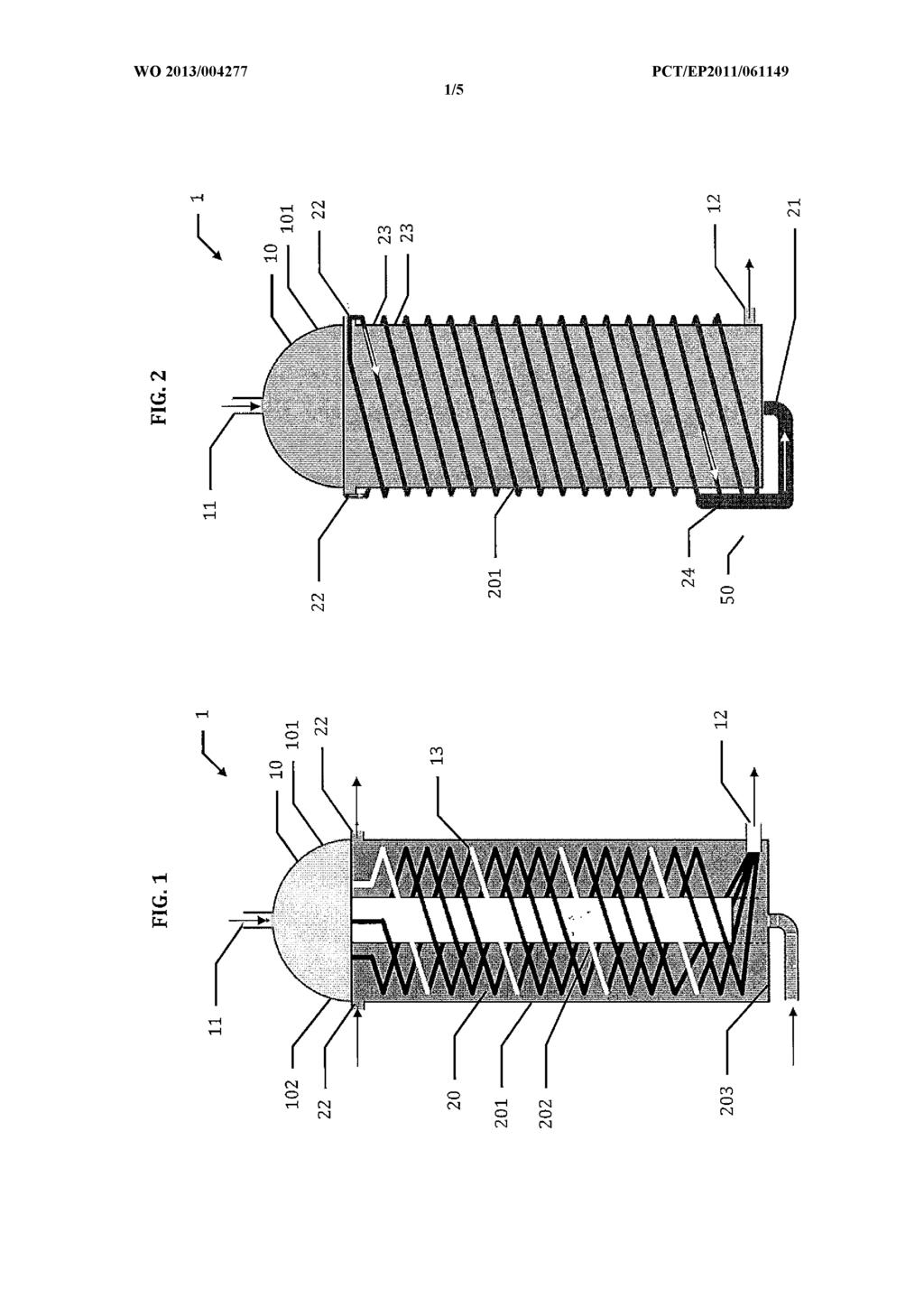
8 shown in each separate embodiment is envisaged and may be applied in order to obtain the similar effect in anther embodiment. Fig. 1 shows a cross sectional side view of a first embodiment of a heat exchanger unit according to the invention; Fig. 2 shows a side view of the heat exchanger unit in figure 1; Fig. 3 shows a cross sectional side view of a heat exchanger unit of a second embodiment of a heat exchanger unit according to the invention. Fig. 4 shows a cross sectional side view of a heat exchanger unit of a third embodiment of a heat exchanger unit according to the invention. Fig. 5 shows a cross sectional side view of a heat exchanger unit of a forth embodiment of a heat exchanger unit according to the invention. Fig. 6 shows a cross sectional side view of a heat exchanger unit of a fifth embodiment of a heat exchanger unit according to the invention. Detailed description of the invention The term "process fluid" is meant to comprise any fluid that is cooled (or heated) by the heat exchanger in order to be processed or transported and possibly further processed later. The term "hydrocarbon containing fluid" is meant to comprise any liquid or gas or mixtures thereof containing hydrocarbons, such as oil and/or gas from a production site, both without or with water in any amount. The term "heat exchanger" is meant to comprise any device or system wherein a fluid is heated or cooled by convection with another fluid due to differences in temperatures. Figure 1 shows a cross sectional view of a first embodiment of the heat exchanger 1 according to the present invention. The heat exchanger 1 comprises a header 10 and a convection section 20 in a shell or enclosure, said header and convection section being
9 sealed from each other by a partition 102. The volume of the header 10 is limited by an enclosure shell 10 1 and the partition 102 and receives process fluid through a process fluid inlet 11. The process fluid received by the header 10 is distributed through the partition 102 into one or more internal convection tubes 13 passing through the convection section 20 which is limited by a cylindrical shell or casing 201, a bottom wall 203 and said partition 102. The header 10 may be a distribution header which in the case of a process fluid containing an oil and gas mixture secures equal distribution of phases in each internal convection tube in order to avoid local concentration of phases in some tubes which might cause deposits. The internal convection tubes 13 are bundled together in a process fluid outlet 12 at the opposite end of the convection section. The layout of the internal convection tubes 13 inside the convection section 20 may vary, but are in this example assembled in a helical manner as shown in figure 1, such as in a helical spiral wound arrangement, wherein a large area of heat transfer may be enabled within a small volume of the convection section. In a spiral wound heat exchanger the overall bundle is formed like a cylindrical device with tubes coiled up in circular layers. All tubes are coiled up with a fixed inclination angle. The final tube coils are arranged in different layers, where each level contains several tubes. The coiling direction of each layer may be the same, or alternating between the layers. All tubes have equal length. Radial and longitudinal pitch between tubes may be flexibly varied. The convection section 20, being limited by the cylindrical casing 201, the bottom wall 203 and said partition 102, further comprises one or more heat exchanging fluid inlets 2 1, and one or more heat exchanging fluid outlets 22, wherein the heat exchanging fluid freely may pass over the helically bundled heat exchanging internal convection tubes 13. The heat exchanging fluid outlets 22 may be oriented in longitudinal direction or radial direction, and several outlets are preferable when directed in the radial direction, to avoid immobilised flow regions in parts of the convection section 20. As shown in figure 1, the exemplified heat exchanger of this embodiment is placed vertically and operated in a counter current mode, wherein the heat exchanging fluid inlet 2 1 is placed close to the sea floor and the heat exchanging fluid outlets 22 are positioned at the top part of the heat convection section 20. The process fluid enters
10 from the topside by the inlet 11 of the heat exchanger 1 and is extracted at the bottom part of the convection section 20 by outlet 12. The vertical positioning of the heat exchanger enables easy draining of liquids in the heat exchanger during shutdowns. The convection section 20 of the heat exchanger 2 may preferably comprise a flow diversion element 202 or turbulence element such as a shroud, positioned in the centre interior of the convection section 20 to direct the heat exchanging fluid more directly over the internal convection tubes and hinder it passing directly through the middle of the spiral arrangement of said tubes. The diversion element 202 can have any suitable shape, and has in this embodiment a cylindrical shape centred in the middle of the convection section with a length shorter than said section, positioned in a vertical distance from the heat exchanging fluid inlet and connected to the partition 102 at the top of the section. This arrangement directs the heat exchanging fluid to the more peripheral areas at the bottom and up over the internal convection tubes 13 and thereafter out to the topside outlets 22. The diversion element 202 may also provide structural strength to the unit and may be used as support for the internal convection tubes 13 inside the heat exchanger. Any suitable diversion elements and/or baffles may be used to direct the flow of the heat exchanging fluid in an optimal fashion. Figure 2 shows an external side view of the heat exchanger 1 in figure 1. The heat exchanging fluid exiting the convection section 20 by the top outlets 22 is lead in external convection pipes 23 arranged in a serpentine manner on the outside of the heat exchanger tank 1 on cylindrical casing 201 towards the bottom end where they are collected in an inlet pipe 24 before entering the heat exchanger again through the heat exchanging fluid inlet 2 1. The number of external convection pipes 23 preferably corresponds to the number of outlets 2 1. The heat transfer between the casing 201 and the external convection pipes 23 is negligible. The heat transfer between casing 201 and the surrounding sea water can contribute to the overall heat transfer. In the mode shown in this embodiment, the heat exchanger 1 is used for cooling a process fluid by heat exchanging with a heat exchanger or cooling fluid circulating in a closed circuit or loop. In this mode, natural convection inside the convection section 20 contributes to an increase in buoyancy of the cooling fluid, which induces upward flow of the cooling fluid. The cooling fluid, being warmed up as the counter streaming process fluid heats it, provides circulation of the cooling fluid from the bottom to the top.
11 With the use of a closed circuit for the heat exchanging fluid, any suitable fluid may be used, for example seawater or glycol. Hence, the heat exchanging fluid may have inherent properties or be provided with properties, such as by additional substances, suitable for enhancing the heat exchanging process, for example in avoiding internal scaling and growth or avoiding or enabling phase change of the heat exchanging fluid. In the same manner that the heat exchanging fluid is heated and rise in the convection section 20 inside the tank 1, the external convection pipes 23 will heat the seawater surrounding the heat exchanger tank 1 and the seawater will rise due to an increase in buoyancy. This will enhance circulation of the seawater as the seawater rise and is replaced by cold seawater. The circulation of seawater may provide a certain counter current heat exchange on the outside of the tank 1, cooling the heat exchanging fluid before it enters the convection section 20 of the heat exchanger 1 again. Normally, sea current will provide an important flow of seawater across the external convection pipes 23 providing convection thereof. In order to control the outlet temperature of the process fluid, the circulation of heat exchanging fluid is controlled. The temperature control may be obtained by flow rate control of the heat exchanging fluid in order to regulate the transfer of heat between the two fluids. Preferably, a circulation means in the form of a pump 50 is used to control the flow rate of the heat exchanging fluid. Alternative circulations means could be any of a propeller or ejector within the convection section 20 for forced circulation of the heat exchanging fluid across the internal convection tubes 13. Figure 3 shows another embodiment of the present invention in a cross sectional view. The heat exchanger tank 2 comprises a convection section 40 limited by a cylindrical shell or casing 401, a bottom wall 403 and a top wall 404, and having a process fluid inlet 3 1 distributing said process fluid in one or more internal convection tubes 33 passing through the convection section 40 and being bundled together in a process fluid outlet 32. The process fluid inlet 3 1 and outlet 32 may have any form and position of connection on the heat exchanger tank 2, for example as shown in figure 1, but are in this embodiment positioned with the process fluid inlet 3 1 and outlet 32 at the top and bottom part respectively of the cylindrical casing 401. The process fluid inlet may also comprise or be connected to a distribution header, such as shown in figures 1, for distributing the process fluid into the internal convection tubes 33.
12 The layout of the internal convection tubes 33 inside the convection section 40 may be assembled in a helical manner as shown in figure 3, similar to the arrangement described above and shown in figure 1, or any other suitable arrangement. The convection section 40 further comprises a heat exchanging fluid inlet 4 1 and outlet 42 in the centre bottom and top part respectively, of the convection section. The heat exchanging fluid may freely pass over the helically bundled heat exchanging internal convection tubes 33. In order to hinder said heat exchanging fluid passing directly through the middle of the spiral arrangement of said internal convection tubes 33, a diversion element 402, shroud or turbulence element is positioned in the centre interior part of the convection section 40 to direct said fluid more directly over said tubes. The diversion element 402 may have any suitable shape, and is in this embodiment a cylindrical shape positioned in the middle of the convection section 40 with a length shorter than said section and positioned in a vertical distance from both the heat exchanging fluid inlet 4 1 and outlet 42. The diversion element directs the heat exchanging fluid out to the more peripheral areas of the convection section 40 at the bottom and up over the internal convection tubes 33, and thereafter back towards the centre again at the top of the convection section 40 towards the outlet 42. The heat exchanger 2 exemplified in figure 3 is also placed vertically and operated in a counter current mode as described above, wherein the heat exchanging fluid inlet 4 1 is placed close to the sea floor and the outlet 42 is positioned at the top of the heat convection section 40. The process fluid enters from the top part of the heat exchanger 2 through process fluid inlet 3 1 and is extracted at the bottom part of the convection section 40 through process fluid outlet 32. In this embodiment both the inlet 3 1 and outlet 32 are positioned at radial positions on the side of the heat exchanger 2. As shown in figure 3, the heat exchanging fluid exiting the convection section 40 by the top outlet 42 is distributed to an external convection circuit 3. The convection circuit 3 may comprise an arrangement for increasing contact area with the seawater, in this example in the form of several external convection pipes 43 arranged in parallel, allowing seawater to surround said pipes and flow in-between. The heat exchanging fluid is cooled while flowing through the convection circuit 3, and especially by flowing through said convection pipes 43 before being collected and lead into the heat exchanger 2 through the inlet 4 1. The heat exchanging fluid may be transported through the convection circuit 3 from the outlet 42 by a pipe 44, via a pump 60 and a second pipe 45 to the external convection pipes 43 through one or more splits. Said
13 external convection pipes 43 may be arranged in any suitable manner, such as one or more of vertical parallel pipes, horizontal or slanted parallel pipes, or helical spiral arrangements such as those described on the inside or outside of the heat exchanger 1, 2 and shown in further detail in figures 4 and 5. The separate convection pipes 43 are then joined and the heat exchanging fluid is lead by a pipe 46 to the inlet 4 1. In the mode of this embodiment, the heat exchanger 2 is used for cooling a process fluid by heat transfer with a heat exchanger convection fluid. This mode induces a natural convection inside the convection section 40 contributing to buoyancy inside the section as described above. The external convection pipes 43 will likewise heat the seawater surrounding them and in the case of still seawater contribute to circulation of the seawater as it is warmed up and replaced by cold seawater. However, prevailing currents of seawater may often contribute to a more important flow of seawater across the external convection pipes 43 in a generally horizontal direction. The circulation may provide a certain counter current heat exchange on the outside of the pipes 43, depending on the orientation of the pipes in relation to existing or generated seawater flow, cooling the heat exchanging fluid before entering the convection section of the heat exchanger again. The flow of seawater around the arranged external convection pipe 43 may also be enhanced and partly controlled by a flow device 70, such as a propeller as shown in figure 3, for forced and partly controllable flow of seawater around the external pipes 43, such as in an upward and/or cross oriented flow to obtain both natural convection and forced convection. In figure 3 a propeller, forcing seawater across the external parallel pipes 43, exemplifies the flow device 70. Likewise an ejector system for circulating seawater may be used, providing seawater flow through the bundle, by high-pressure seawater being pumped through a single main pipe where secondary seawater is ejected into the flow. The main sea water supply system then has high pressure and low volumetric flow, reducing pump capacity (but increasing pump head). The flow rate of seawater may be controlled to a certain extent and thereby controlling heat transfer, temperature profile and inlet temperature of the heat exchanging fluid to the convection section. A pump system supplying power to the ejector system may be used. In order to control the outlet temperature of the process fluid at outlet 32, the circulation of heat exchanging fluid may be controlled. The temperature control may be obtained
14 by flow rate control of the heat exchanging fluid in order to regulate the transfer of heat between the two fluids. A pump 60 may control the flow rate of the heat exchanging fluid, securing correct heat transfer rate between the heat exchanging fluid and the process fluid. The temperature of the heat exchanging fluid is further adjustable by the flow device 70 which may provide increased convection and thereby an increased temperature difference of the heat exchanging fluid from outlet to inlet. Alternatively or in addition, the flow device 70 may contribute in keeping the inlet temperature of the heat exchanging fluid at inlet 4 1 constant by increasing or decreasing seawater flow over the pipes 43 in adjustment to changes in sea temperature and especially changes in currents. The external convection circuit 3 may also comprise a hydrostatic equalizer 6 1 to pressurize the inside of the pipe members of the convection circuit so that the internal pressure is balanced with the seawater on the outside. In addition the convection circuit 3 may optionally comprise a buffer tank for heat exchanging fluid (not shown). Differences in pressure on the inside of subsea pipes and tubing or any equipment necessitate thick walled elements to withstand the hydrostatic pressure of the seawater at the actual sea depth. By pressure balancing the pipes and tubes and other elements of the external convection circuit, and especially the external convection pipes, the thickness of said pipes may be reduced and more effective cooling is obtained with the seawater. Also, such pressure balancing allows for the use of other pipe materials than steel, such as for example aluminum. In order to further control the cooling of the heat exchanging fluid, a bypass line 47 of the convection circuit 3 with the external convection pipes 43 may be present, with a flow controlling valve 48 regulating the amount of fluid bypassing the external convection pipes 43. The amount of heat exchanging fluid passing through the bypass line 47 will influence the final temperature of the heat exchanging fluid entering the convection section 40 at inlet 4 1 as the fluids from the bypass 47 and fluid having been cooled further in the external convection pipes 43 are mixed in rates depending on the controlling valve 48. Hence the circulation pump 60 may run at constant speed while the valve 48 controls the resulting temperature at the inlet 4 1. With a seawater temperature in the range of 0-4 C the inlet temperature of the heat exchanging fluid may for example be adjusted to be within a temperature interval of about C. The bypass 47 is also advantageous in the case of possible leaks in the system, such as in the external convection pipes 43.
15 Figure 4 show s a heat exchanger similar to figure 3 wherein the external convection pipes 53 of the convection circuit 3 are arranged in a helical spiral manner as a vertical tube in a vertical position. In this configuration the seawater may be heated and contribute to circulation over the pipes and through the tube form of the pipe arrangement, due to increase in buoyancy as the seawater is warmed up and replaced by cold seawater. An optional bypass line 47 of the external convection pipes 53 with a flow-controlling valve 48 regulating the amount of fluid bypassing the external convection pipes 53 is also shown. The valve 48 provides the possibility to account for differences in temperature and currents of the seawater affecting the final temperature of the fluid exiting the external convection pipes 53, when no flow device is present to adjust seawater flow around the external convection pipes 53. Figure 5 shows a further embodiment of a heat exchanger similar to figure 3 and 4 wherein the external convection pipes 54 of the convection circuit 3 also are arranged in a helical spiral manner as a tube, but wherein the tube is positioned in a horizontal manner. In order to obtain further control of the cooling or heating effect of the external convection pipes 54, the pipes are in this embodiment partly encased in an optional cylindrical casing 7 1 with open ends, wherein seawater flow over external convection pipes 54 is controlled by a flow device 70. A propeller here exemplifies the flow device 70, but an ejector or similar device may also be used for forced flow of seawater over and around said convection pipes 54 for forced convection. In a further embodiment, the casing 7 1 may also comprise baffles or devices to close and open one or both the end openings of the casing (not shown), such as to further control through flow, or for closing the casing 7 1 such as for cleaning purposes. As mentioned above, the heat exchanger of the present invention may also be used for heating process fluids, by heat exchanging with seawater warmer than the process fluid. Figure 6 shows a further embodiment of a heat exchanger according to the present invention wherein a heat exchanger 102 with convection circuit 103 may be used as a vapour compression refrigeration system. The heat exchanger 103 is similar to the heat exchangers of the former embodiments of figures 3, 4 and 5 except for a heat
16 exchanging fluid inlet 141 positioned on the side wall of its casing 201, at a vertical distance from the bottom of said heat exchanger 102, instead of at the bottom. The convection circuit 103 is also similar to the embodiment of figures 3, 4 and 5, but comprises a compressor 160 instead of a pump and in addition an expansion valve 164 on the convection circuit before heat exchanging fluid inlet 141 of the heat exchanger. Hence, in the present embodiment, the heat exchanger and convection circuit is adapted for using a refrigerant circulating as heat exchanging fluid, for example propane. The heat exchanger 102 functions as an evaporator. By exchanging heat with the refrigerant, which is evaporated, the process fluid running through the internal convection tubes 233 is cooled. The gas phase refrigerant vapour leaves the convection section 240 of the heat exchanger 102 by the heat exchanger fluid outlet 142 and fed by a pipe 144 to the compressor 160 where the vapour is compressed. The compressed vapour gas is transported to an arrangement of external convection pipes 153 by a pipe 145. In this embodiment the external convection pipes 153 of the convection circuit 103 are arranged in a helical spiral manner as a vertical tube in a vertical position as in figure 4. The arrangement of the convection pipes may however have any form which is suitable, for example any of the above mentioned set ups or other suitable arrangements. The external convection pipes 153 function as a condenser wherein the compressed refrigerant vapour is condensed to mainly comprising a liquid by the heat exchange with the cool seawater. The liquid refrigerant from the convection pipes 153 is transported by a pipe 146 to said expansion valve 164 from which the refrigerant exits as a two-phase fluid mixture and enters the convection section 240 of the heat exchanger 102 by the inlet 141. Said inlet may be positioned above the liquid level of the refrigerant in the heat exchanger as shown in figure 6, leaving the heat exchanging tubes 233 partly immersed in the liquid phase 203 of the refrigerant, and space for the refrigerant vapour 204 in a top part of the convection section 240. The process described above will function even with varying effect on the external convection pipes 153 towards the seawater as the variation in cooling will give rise to a variation in the ratio of gas and liquid from the expansion valve. The temperature of the stream entering the convection zone 240 by inlet 141 will be constant and the cooling
17 of the hydrocarbon fluid may be controlled by regulating the circulation rate of the compressor 160 to account for variations in cooling from the sea currents. The convection system described above may for example be use as a second stage in the cooling of hydrocarbon fluid where essentially most of the water has been knocked out by an earlier cooling and separation stage. The unit and the process may for example be used to reduce the dew point of a hydrocarbon gas below the seawater temperature, such as for producing dry sales gas. Example A cooling system according to the embodiments of figures 3-5 may receive a warm hydrocarbon gas produced from a subsea well at about 100 bar and 80 C in the amounts of about 60 kg/s. An inlet passes said gas to the internal convection section of the heat exchanger and passes the gas on the inside of the convection tubes thereof where the gas may be cooled down to an exit temperature of about 25 C. The heat exchanging fluid, in this case water in the amount of about 55 kg/s enters the heat exchanger at about 15 C and 30 bar and passes over the outside surface of said convection tubes within the heat exchanger casing through the internal convection section thereof and is heated to an exit temperature of about 60 C. The heat exchanging fluid is then directed through the external convection circuit where it is cooled down to about 15 C before entering the internal convection section. The amount of seawater at about 4 C and 30 bar necessary for obtaining the mentioned cooling of the heat exchanging fluid is order of 3500 kg/s which passes over the external circuit, and especially the convection pipes, either by natural current or by forced flow by the use of a flow device as mentioned in the embodiment above. Compared to subsea heat exchangers of prior art wherein seawater is used in direct contact with convection tubes carrying the process fluids, the present invention makes use of a closed circuit containing a heat exchanging fluid for heat transfer with said convection tubes and which in turn exchanges heat with the sea water by external convection tubes. Hence, the surface temperature of the external convection circuit, i.e. pipes 23, 43, 53, 54 and 154 is reduced compared to the surface temperature of the internal tubes 13 and 33 and may be held below the temperature at which scaling occurs and at a temperature where marine growth and corrosion is reduced. In
18 addition, the external positioning of the external convection circuit may enable physical scraping and removal of marine fouling and improved fouling control. The present invention therefore also increases control of fouling and hence limits the need for overcapacity in construction of subsea heat exchangers and provides a more precise control of the temperature. Most prior art subsea coolers are of the passive type, or have only limited means of controlling direct flow of seawater across the hydrocarbon fluid containing heatexchanging tubes. The lack of exactness of temperature control of these former coolers therefore limits the temperature level at said coolers safely may cool a hydrocarbon fluid to without risking hydrate or other deposits. The invention provides the possibility to control fluid temperature on the tube side (such as hot fluid) at all turndown rates, and may use either forced convection or free convection on the seawater side. The temperature of the process flow is controllable and the risk of hydrate formation is considerably reduced. The closed circuit allows for more complex tube arrangements as well as deviation elements and baffles inside the convection section of the heat exchanger, as scaling and marine growth is eliminated. The heat exchanging fluid may be water or any mixture of water or glycol or any mixtures thereof and may contain scaling and growth inhibitors such as biocides or cleaning chemicals that keep the closed circuit free of contaminants and deposits. It should be noted that the process fluid, which in general will be a hydrocarbon containing fluid is preferably run through the convection tube side of the internal convection tubes 13 and 33 in order to obtain a homogenous cooling of the fluid, although the opposite is possible by running the closed circuit connected with heat exchanging fluid to the internal convection tubes 13 or 33 for a moderate heat exchange. The criteria for this opposite operation mode would be that the hydrocarbon containing fluid is not cooled below any wax and/or hydrate formation temperature, and hence would not allow any precise control as the temperature within the convection section vary with regard to distance and contact with the internal convection tubes.
19 Claims 1. A subsea heat exchanger for cooling or heating a hydrocarbon-containing fluid, said heat exchanger comprising; a convection section enclosed by a shell or enclosure comprising: o one or more heat exchanging fluid inlet(s) and outlet(s); o one or more hydrocarbon-containing fluid inlet(s) and outlet(s); and o one or more fluid carrying convection tube(s) adapted for heat transfer between the hydrocarbon-containing fluid on the inside of the tube(s) and a surrounding heat exchanging fluid on the opposite side of the tube(s), wherein the heat exchanger is provided with one or more flow regulating device(s) for controlling the hydrocarbon-containing fluid outlet temperature, characterized in that the heat exchanging fluid circulates in a closed circuit for heat transfer both with said hydrocarbon-containing fluid and with surrounding sea water on the outside of the enclosure. 2. A heat exchanger according to claim 1, wherein the flow regulating device is a pump or a compressor regulating the flow rate of heat exchanging fluid. 3. A heat exchanger according to claim 1 or 2, wherein the convection tube(s) inside the convection section are coiled in a helical manner. 4. A heat exchanger according to any of the preceding claims, wherein the heat exchanger is positioned vertically, optionally for ease of draining. 5. A heat exchanger according to any of the preceding claims, wherein the closed circuit comprises one or more external convection pipes adapted for heat transfer between the heat exchanging fluid on the inside of the tube(s) and surrounding sea water on the opposite side of the tube(s). 6.
20 A heat exchanger according to any of the preceding claims, wherein two or more external convection pipes are arranged in one of: a free standing parallel arrangement in a horizontal, vertical or slanted arrangement; a helical arrangement in a free standing manner; or coiled around the heat exchanger enclosure. 7. A heat exchanger according to any of the preceding claims, wherein the flow regulating device is a propeller or ejector for increasing flow of surrounding seawater across the external convection pipes, optionally wherein the convection pipes are bundled within an open ended cylindrical casing. 8. A heat exchanger according to any of the preceding claims, wherein the hydrocarboncontaining fluid and heat exchanging fluid flow in a co-current or counter current manner. 9. A heat exchanger according to any of the preceding claims, wherein the heat exchanging fluid flow can be reversed. 10. A heat exchanger according to any of the preceding claims, wherein the external convection pipes and/or the internal convection pipes are equipped with an electrical heating. 11. A heat exchanger according to any of the preceding claims, wherein the heat exchanger comprises a distribution header at the inlet of the hydrocarbon containing fluid, optionally for distributing gas and liquid phase hydrocarbon-containing fluid in equal ratios in all internal convection tubes. 12. A heat exchanger according to any of the preceding claims, wherein the closed convection circuit comprises a bypass circuit bypassing the external convection pipes. 13. A heat exchanger according to claim, wherein the flow regulating device is a valve in
21 the bypass circuit regulating the mixing rate of heat exchanging fluid passing through the external convection pipes and the bypass. 14. A heat exchanger according to any of the preceding claims, wherein the hydrocarboncontaining fluid is a mainly a gas. 15. A heat exchanger accordion any of the preceding claims, wherein the flow device is a compressor and the closed circuit comprises an expansion valve, optionally at the heat exchanger fluid inlet of the convection section. 16. A method for subsea cooling or heating of a hydrocarbon containing fluid comprising: passing said hydrocarbon containing fluid through one or more convection tubes in an enclosed convection section of a subsea heat exchanger; and passing a heat exchanging fluid around said convection tubes within said enclosed convection section in order to cool or heat the hydrocarbon containing fluid; characterized in circulating said heat exchanging fluid in a closed circuit through seawater on the outside of the enclosed convection section in order to cool or heat the heat exchanging fluid before entering the enclosed convection section of the heat exchanger again. 17. A method according to claim 16, wherein the temperature of the hydrocarbon containing fluid leaving the convection section of the heat exchanger is regulated by the flow rate of the heat exchanging fluid, optionally by a pump or a compressor. 18. A method according to claim 16 or 17 where the heat exchanging fluid is passed through one or more external convection pipes of the closed circuit in seawater on the outside of the enclosed convection section. 19. A method according to claim 18, wherein the temperature of the hydrocarbon containing fluid leaving the convection section of the heat exchanger is regulated by
22 forcing a current of seawater around said external convection pipes, optionally by a propeller or ejector. 20. A method according to any of the claims , wherein some of the heat exchanging fluid passing in the closed circuit through seawater is passed through a bypass line, bypassing the one or more external convection pipes, and wherein the mixing rate is regulated by at least one valve in the bypass line and/or the line comprising the external convection pipe(s) A method according to claim 20, wherein the temperature of the hydrocarbon containing fluid leaving the convection section of the heat exchanger is regulated by the mixing rate of the heat exchanging fluids passing in the bypass line and/or the line comprising the external convection pipe(s). 22. The use of a heat exchanger according to any of the claims 1-15 or a method according to any of the claims for cooling or heating a hydrocarbon containing fluid at subsea.
23
(43) International Publication Date _. _... _. 10 May 2012 ( ) WO 2012/ Al
 International Publication Date _. _... _. 10 May 2012 ( ) WO 2012/ Al") (12) INTERNATIONAL APPLICATION PUBLISHED UNDER THE PATENT COOPERATION TREATY (PCT) (19) World Intellectual Property Organization International Bureau (10) International Publication Number (43) International
(12) INTERNATIONAL APPLICATION PUBLISHED UNDER THE PATENT COOPERATION TREATY (PCT) (19) World Intellectual Property Organization International Bureau (10) International Publication Number (43) International
EP A2 (19) (11) EP A2 (12) EUROPEAN PATENT APPLICATION. (43) Date of publication: Bulletin 2010/52
 (11) EP A2 (12) EUROPEAN PATENT APPLICATION. (43) Date of publication: Bulletin 2010/52") (19) (12) EUROPEAN PATENT APPLICATION (11) EP 2 267 391 A2 (43) Date of publication: 29.12.2010 Bulletin 2010/52 (51) Int Cl.: F28D 9/00 (2006.01) F28F 3/04 (2006.01) (21) Application number: 10167552.8
(19) (12) EUROPEAN PATENT APPLICATION (11) EP 2 267 391 A2 (43) Date of publication: 29.12.2010 Bulletin 2010/52 (51) Int Cl.: F28D 9/00 (2006.01) F28F 3/04 (2006.01) (21) Application number: 10167552.8
PCT WO 2008/ Al
 (12) INTERNATIONAL APPLICATION PUBLISHED UNDER THE PATENT COOPERATION TREATY (PCT) (19) World Intellectual Property Organization International Bureau (43) International Publication Date (10) International
Place East, 3433 Broadway Street Northeast, Minneapolis, (21) International Application Number:
 International Application Number:") (12) INTERNATIONAL APPLICATION PUBLISHED UNDER THE PATENT COOPERATION TREATY (PCT) (19) World Intellectual Property Organization International Bureau (10) International Publication Number (43) International
(12) INTERNATIONAL APPLICATION PUBLISHED UNDER THE PATENT COOPERATION TREATY (PCT) (19) World Intellectual Property Organization International Bureau (10) International Publication Number (43) International
EP A2 (19) (11) EP A2 (12) EUROPEAN PATENT APPLICATION. (43) Date of publication: Bulletin 2012/50
 (11) EP A2 (12) EUROPEAN PATENT APPLICATION. (43) Date of publication: Bulletin 2012/50") (19) (12) EUROPEAN PATENT APPLICATION (11) EP 2 32 983 A2 (43) Date of publication: 12.12.12 Bulletin 12/0 (21) Application number: 1216990.2 (1) Int Cl.: F24H 4/04 (06.01) F2B /02 (06.01) F2B 47/02 (06.01)
(19) (12) EUROPEAN PATENT APPLICATION (11) EP 2 32 983 A2 (43) Date of publication: 12.12.12 Bulletin 12/0 (21) Application number: 1216990.2 (1) Int Cl.: F24H 4/04 (06.01) F2B /02 (06.01) F2B 47/02 (06.01)
TEPZZ 9Z5549A T EP A2 (19) (11) EP A2 (12) EUROPEAN PATENT APPLICATION. (51) Int Cl.: F24F 1/06 ( ) F24F 1/46 (2011.
 (11) EP A2 (12) EUROPEAN PATENT APPLICATION. (51) Int Cl.: F24F 1/06 ( ) F24F 1/46 (2011.") (19) TEPZZ 9Z5549A T (11) EP 2 905 549 A2 (12) EUROPEAN PATENT APPLICATION (43) Date of publication: 12.08.2015 Bulletin 2015/33 (51) Int Cl.: F24F 1/06 (2011.01) F24F 1/46 (2011.01) (21) Application number:
(19) TEPZZ 9Z5549A T (11) EP 2 905 549 A2 (12) EUROPEAN PATENT APPLICATION (43) Date of publication: 12.08.2015 Bulletin 2015/33 (51) Int Cl.: F24F 1/06 (2011.01) F24F 1/46 (2011.01) (21) Application number:
Published: with international search report (Art. 21(3))
)") (12) INTERNATIONAL APPLICATION PUBLISHED UNDER THE PATENT COOPERATION TREATY (PCT) (19) World Intellectual Property Organization International Bureau (10) International Publication Number (43) International
(12) INTERNATIONAL APPLICATION PUBLISHED UNDER THE PATENT COOPERATION TREATY (PCT) (19) World Intellectual Property Organization International Bureau (10) International Publication Number (43) International
WO 2017/ Al I X. n Io o o o o o o o o o o o o o o o o o. (10) International Publication Number (43) International Publication Date
 International Publication Number (43) International Publication Date") (12) INTERNATIONAL APPLICATION PUBLISHED UNDER THE PATENT COOPERATION TREATY (PCT) (19) World Intellectual Property Organization International Bureau (10) International Publication Number (43) International
(12) INTERNATIONAL APPLICATION PUBLISHED UNDER THE PATENT COOPERATION TREATY (PCT) (19) World Intellectual Property Organization International Bureau (10) International Publication Number (43) International
25 November 2010 ( ) WO 2010/ Al
 WO 2010/ Al") (12) INTERNATIONALAPPLICATION PUBLISHED UNDER THE PATENT COOPERATION TREATY (PCT) (19) World Intellectual Property Organization International Bureau (43) International Publication Date (10) International
(12) INTERNATIONALAPPLICATION PUBLISHED UNDER THE PATENT COOPERATION TREATY (PCT) (19) World Intellectual Property Organization International Bureau (43) International Publication Date (10) International
TEPZZ 87_ 6A_T EP A1 (19) (11) EP A1 (12) EUROPEAN PATENT APPLICATION
 (11) EP A1 (12) EUROPEAN PATENT APPLICATION") (19) TEPZZ 87_ 6A_T (11) EP 2 871 336 A1 (12) EUROPEAN PATENT APPLICATION (43) Date of publication: 13.0.1 Bulletin 1/ (21) Application number: 1319173.3 (1) Int Cl.: F01K 13/02 (06.01) F22B 3/00 (06.01)
(19) TEPZZ 87_ 6A_T (11) EP 2 871 336 A1 (12) EUROPEAN PATENT APPLICATION (43) Date of publication: 13.0.1 Bulletin 1/ (21) Application number: 1319173.3 (1) Int Cl.: F01K 13/02 (06.01) F22B 3/00 (06.01)
TEPZZ _87768A_T EP A1 (19) (11) EP A1 (12) EUROPEAN PATENT APPLICATION. (43) Date of publication: Bulletin 2017/27
 (11) EP A1 (12) EUROPEAN PATENT APPLICATION. (43) Date of publication: Bulletin 2017/27") (19) TEPZZ _87768A_T (11) EP 3 187 768 A1 (12) EUROPEAN PATENT APPLICATION (43) Date of publication: 0.07.17 Bulletin 17/27 (21) Application number: 16462.9 (1) Int Cl.: F16N 29/00 (06.01) F16C 33/66 (06.01)
(19) TEPZZ _87768A_T (11) EP 3 187 768 A1 (12) EUROPEAN PATENT APPLICATION (43) Date of publication: 0.07.17 Bulletin 17/27 (21) Application number: 16462.9 (1) Int Cl.: F16N 29/00 (06.01) F16C 33/66 (06.01)
TEPZZ _ 7455A_T EP A1 (19) (11) EP A1 (12) EUROPEAN PATENT APPLICATION
 (11) EP A1 (12) EUROPEAN PATENT APPLICATION") (19) TEPZZ _ 7455A_T (11) EP 3 127 455 A1 (12) EUROPEAN PATENT APPLICATION (43) Date of publication: 08.02.2017 Bulletin 2017/06 (21) Application number: 16156729.2 (51) Int Cl.: A47C 19/00 (2006.01) A47C
(19) TEPZZ _ 7455A_T (11) EP 3 127 455 A1 (12) EUROPEAN PATENT APPLICATION (43) Date of publication: 08.02.2017 Bulletin 2017/06 (21) Application number: 16156729.2 (51) Int Cl.: A47C 19/00 (2006.01) A47C
TEPZZ Z564 A_T EP A1 (19) (11) EP A1 (12) EUROPEAN PATENT APPLICATION. (51) Int Cl.: B64D 13/06 ( ) B64D 13/08 (2006.
 (11) EP A1 (12) EUROPEAN PATENT APPLICATION. (51) Int Cl.: B64D 13/06 ( ) B64D 13/08 (2006.") (19) TEPZZ Z64 A_T (11) EP 3 06 433 A1 (12) EUROPEAN PATENT APPLICATION (43) Date of publication: 17.08.16 Bulletin 16/33 (1) Int Cl.: B64D 13/06 (06.01) B64D 13/08 (06.01) (21) Application number: 16127.7
(19) TEPZZ Z64 A_T (11) EP 3 06 433 A1 (12) EUROPEAN PATENT APPLICATION (43) Date of publication: 17.08.16 Bulletin 16/33 (1) Int Cl.: B64D 13/06 (06.01) B64D 13/08 (06.01) (21) Application number: 16127.7
EP A2 (19) (11) EP A2 (12) EUROPEAN PATENT APPLICATION. (51) Int Cl.: G08B 17/06 ( ) G08B 17/103 (2006.
 (11) EP A2 (12) EUROPEAN PATENT APPLICATION. (51) Int Cl.: G08B 17/06 ( ) G08B 17/103 (2006.") (19) (12) EUROPEAN PATENT APPLICATION (11) EP 2 2 9 A2 (43) Date of publication: 04.01.12 Bulletin 12/01 (1) Int Cl.: G08B 17/06 (06.01) G08B 17/3 (06.01) (21) Application number: 11171928.2 (22) Date
(19) (12) EUROPEAN PATENT APPLICATION (11) EP 2 2 9 A2 (43) Date of publication: 04.01.12 Bulletin 12/01 (1) Int Cl.: G08B 17/06 (06.01) G08B 17/3 (06.01) (21) Application number: 11171928.2 (22) Date
TEPZZ A T EP A2 (19) (11) EP A2 (12) EUROPEAN PATENT APPLICATION. (51) Int Cl.: F25D 25/02 ( )
 (11) EP A2 (12) EUROPEAN PATENT APPLICATION. (51) Int Cl.: F25D 25/02 ( )") (19) TEPZZ 7 8 84A T (11) EP 2 728 284 A2 (12) EUROPEAN PATENT APPLICATION (43) Date of publication: 07.0.14 Bulletin 14/19 (1) Int Cl.: F2D 2/02 (06.01) (21) Application number: 13191. (22) Date of filing:
(19) TEPZZ 7 8 84A T (11) EP 2 728 284 A2 (12) EUROPEAN PATENT APPLICATION (43) Date of publication: 07.0.14 Bulletin 14/19 (1) Int Cl.: F2D 2/02 (06.01) (21) Application number: 13191. (22) Date of filing:
ZM, ZW), Eurasian (AM, AZ, BY, KG, KZ, MD, RU, TJ, Robert, D. [US/US]; Eastlake Av. E. #405, Seattle,
![ZM, ZW), Eurasian (AM, AZ, BY, KG, KZ, MD, RU, TJ, Robert, D. [US/US]; Eastlake Av. E. #405, Seattle,](/thumbs/90/103695988.jpg "ZM, ZW), Eurasian (AM, AZ, BY, KG, KZ, MD, RU, TJ, Robert, D. [US/US]; Eastlake Av. E. #405, Seattle,") (12) INTERNATIONAL APPLICATION PUBLISHED UNDER THE PATENT COOPERATION TREATY (PCT) (19) World Intellectual Property Organization International Bureau (10) International Publication Number (43) International
(12) INTERNATIONAL APPLICATION PUBLISHED UNDER THE PATENT COOPERATION TREATY (PCT) (19) World Intellectual Property Organization International Bureau (10) International Publication Number (43) International
EP A1 (19) (11) EP A1 (12) EUROPEAN PATENT APPLICATION. (43) Date of publication: Bulletin 2010/17
 (11) EP A1 (12) EUROPEAN PATENT APPLICATION. (43) Date of publication: Bulletin 2010/17") (19) (12) EUROPEAN PATENT APPLICATION (11) EP 2 179 656 A1 (43) Date of publication: 28.04.2010 Bulletin 2010/17 (51) Int Cl.: A22C 7/00 (2006.01) (21) Application number: 09013444.6 (22) Date of filing:
(19) (12) EUROPEAN PATENT APPLICATION (11) EP 2 179 656 A1 (43) Date of publication: 28.04.2010 Bulletin 2010/17 (51) Int Cl.: A22C 7/00 (2006.01) (21) Application number: 09013444.6 (22) Date of filing:
(43) International Publication Date Χ t i t i n 9 September 2011 ( ) WO 2 11/ A l
 International Publication Date Χ t i t i n 9 September 2011 ( ) WO 2 11/ A l") (12) INTERNATIONAL APPLICATION PUBLISHED UNDER THE PATENT COOPERATION TREATY (PCT) (19) World Intellectual Property Organization International Bureau (10) International Publication Number (43) International
(12) INTERNATIONAL APPLICATION PUBLISHED UNDER THE PATENT COOPERATION TREATY (PCT) (19) World Intellectual Property Organization International Bureau (10) International Publication Number (43) International
LV, MC, MK, MT, NL, NO, PL, PT, RO, RS, SE, SI, SK, Guangdong (CN). WU, Mengxiang; No. 3009,
. WU, Mengxiang; No. 3009,") (12) INTERNATIONAL APPLICATION PUBLISHED UNDER THE PATENT COOPERATION TREATY (PCT) (19) World Intellectual Property Organization International Bureau (10) International Publication Number (43) International
(12) INTERNATIONAL APPLICATION PUBLISHED UNDER THE PATENT COOPERATION TREATY (PCT) (19) World Intellectual Property Organization International Bureau (10) International Publication Number (43) International
(51) Int Cl.: F03D 11/00 ( )
 Int Cl.: F03D 11/00 ( )") (19) TEPZZ _8 _B_T (11) EP 2 18 31 B1 (12) EUROPEAN PATENT SPECIFICATION (4) Date of publication and mention of the grant of the patent: 23.09.1 Bulletin 1/39 (1) Int Cl.: F03D 11/00 (06.01) (21) Application
(19) TEPZZ _8 _B_T (11) EP 2 18 31 B1 (12) EUROPEAN PATENT SPECIFICATION (4) Date of publication and mention of the grant of the patent: 23.09.1 Bulletin 1/39 (1) Int Cl.: F03D 11/00 (06.01) (21) Application
EP A1 (19) (11) EP A1 (12) EUROPEAN PATENT APPLICATION. (43) Date of publication: Bulletin 2006/21
 (11) EP A1 (12) EUROPEAN PATENT APPLICATION. (43) Date of publication: Bulletin 2006/21") (19) Europäisches Patentamt European Patent Office Office européen des brevets (12) EUROPEAN PATENT APPLICATION (11) EP 1 659 040 A1 (43) Date of publication: 24.05.2006 Bulletin 2006/21 (51) Int Cl.:
(19) Europäisches Patentamt European Patent Office Office européen des brevets (12) EUROPEAN PATENT APPLICATION (11) EP 1 659 040 A1 (43) Date of publication: 24.05.2006 Bulletin 2006/21 (51) Int Cl.:
TEPZZ _54Z 7A_T EP A1 (19) (11) EP A1 (12) EUROPEAN PATENT APPLICATION
 (11) EP A1 (12) EUROPEAN PATENT APPLICATION") (19) TEPZZ _4Z 7A_T (11) EP 3 14 037 A1 (12) EUROPEAN PATENT APPLICATION (43) Date of publication: 12.04.17 Bulletin 17/1 (21) Application number: 119937.3 (1) Int Cl.: G08B 21/02 (06.01) B60R 21/01 (06.01)
(19) TEPZZ _4Z 7A_T (11) EP 3 14 037 A1 (12) EUROPEAN PATENT APPLICATION (43) Date of publication: 12.04.17 Bulletin 17/1 (21) Application number: 119937.3 (1) Int Cl.: G08B 21/02 (06.01) B60R 21/01 (06.01)
TEPZZ 8 459A_T EP A1 (19) (11) EP A1. (12) EUROPEAN PATENT APPLICATION published in accordance with Art.
 (11) EP A1. (12) EUROPEAN PATENT APPLICATION published in accordance with Art.") (19) TEPZZ 8 49A_T (11) EP 2 832 49 A1 (12) EUROPEAN PATENT APPLICATION published in accordance with Art. 13(4) EPC (43) Date of publication: 04.02.1 Bulletin 1/06 (21) Application number: 13770017. (22)
(19) TEPZZ 8 49A_T (11) EP 2 832 49 A1 (12) EUROPEAN PATENT APPLICATION published in accordance with Art. 13(4) EPC (43) Date of publication: 04.02.1 Bulletin 1/06 (21) Application number: 13770017. (22)
Installation and converting instructions to another gas type T4530, T4650
 GB, IE Read the technical installing the appliance. Read the user lighting the appliance. This appliance may only be installed in a room if the room meets the appropriate ventilation requirements specified
(51) Int Cl.: F17C 5/02 ( ) F17C 7/04 ( )
 Int Cl.: F17C 5/02 ( ) F17C 7/04 ( )") (19) TEPZZ 948 9B_T (11) EP 2 94 839 B1 (12) EUROPEAN PATENT SPECIFICATION (4) Date of publication and mention of the grant of the patent: 04.06.14 Bulletin 14/23 (1) Int Cl.: F17C /02 (06.01) F17C 7/04
(19) TEPZZ 948 9B_T (11) EP 2 94 839 B1 (12) EUROPEAN PATENT SPECIFICATION (4) Date of publication and mention of the grant of the patent: 04.06.14 Bulletin 14/23 (1) Int Cl.: F17C /02 (06.01) F17C 7/04
PCT GB, GD, GE, GH, GM, GT, HN, HR, HU, ID, IL, IN, IS, JP, KE, KG, KM, KN, KP, KR, KZ, LA, LC, LK, LR, LS,
 (12) INTERNATIONAL APPLICATION PUBLISHED UNDER THE PATENT COOPERATION TREATY (PCT) (19) World Intellectual Property Organization International Bureau (43) International Publication Date (10) International
TEPZZ 67_497A T EP A2 (19) (11) EP A2 (12) EUROPEAN PATENT APPLICATION. (51) Int Cl.: A47L 15/42 ( )
 (11) EP A2 (12) EUROPEAN PATENT APPLICATION. (51) Int Cl.: A47L 15/42 ( )") (19) TEPZZ 67_497A T (11) EP 2 671 497 A2 (12) EUROPEAN PATENT APPLICATION (43) Date of publication: 11.12.13 Bulletin 13/50 (51) Int Cl.: A47L 15/42 (06.01) (21) Application number: 13170429.8 (22) Date
(19) TEPZZ 67_497A T (11) EP 2 671 497 A2 (12) EUROPEAN PATENT APPLICATION (43) Date of publication: 11.12.13 Bulletin 13/50 (51) Int Cl.: A47L 15/42 (06.01) (21) Application number: 13170429.8 (22) Date
MINI ME USER MANUAL.
 MINI ME USER MANUAL www.dolce-gusto.com TABLE OF CONTENTS 1. SAFETY PRECAUTIONS...3 2. MACHINE OVERVIEW...5 3. BEVERAGE EXAMPLES...6 4. RECOMMENDATIONS FOR SAFE USE...7 5. FIRST USE...8 6. PREPARING A
(51) Int Cl.: A01G 25/02 ( )
 Int Cl.: A01G 25/02 ( )") (19) Europäisches Patentamt European Patent Office Office européen des brevets (12) EUROPEAN PATENT APPLICATION (11) EP 1 695 614 A1 (43) Date of publication: 30.08.2006 Bulletin 2006/35 (51) Int Cl.:
(19) Europäisches Patentamt European Patent Office Office européen des brevets (12) EUROPEAN PATENT APPLICATION (11) EP 1 695 614 A1 (43) Date of publication: 30.08.2006 Bulletin 2006/35 (51) Int Cl.:
WO 2008/ Al PCT. (19) World Intellectual Property Organization International Bureau
 World Intellectual Property Organization International Bureau") (12) INTERNATIONAL APPLICATION PUBLISHED UNDER THE PATENT COOPERATION TREATY (PCT) (19) World Intellectual Property Organization International Bureau (43) International Publication Date (10) International
(12) INTERNATIONAL APPLICATION PUBLISHED UNDER THE PATENT COOPERATION TREATY (PCT) (19) World Intellectual Property Organization International Bureau (43) International Publication Date (10) International
TEPZZ Z75 6 A_T EP A1 (19) (11) EP A1. (12) EUROPEAN PATENT APPLICATION published in accordance with Art.
 (11) EP A1. (12) EUROPEAN PATENT APPLICATION published in accordance with Art.") (19) TEPZZ Z7 6 A_T (11) EP 3 07 262 A1 (12) EUROPEAN PATENT APPLICATION published in accordance with Art. 13(4) EPC (43) Date of publication: 0..16 Bulletin 16/ (21) Application number: 14866382.6 (22)
(19) TEPZZ Z7 6 A_T (11) EP 3 07 262 A1 (12) EUROPEAN PATENT APPLICATION published in accordance with Art. 13(4) EPC (43) Date of publication: 0..16 Bulletin 16/ (21) Application number: 14866382.6 (22)
TEPZZ 579 6A T EP A2 (19) (11) EP A2 (12) EUROPEAN PATENT APPLICATION. (51) Int Cl.: G08B 29/14 ( )
 (11) EP A2 (12) EUROPEAN PATENT APPLICATION. (51) Int Cl.: G08B 29/14 ( )") (19) TEPZZ 79 6A T (11) EP 2 79 226 A2 (12) EUROPEAN PATENT APPLICATION (43) Date of publication:.04.13 Bulletin 13/1 (1) Int Cl.: G08B 29/14 (06.01) (21) Application number: 12186987.9 (22) Date of filing:
(19) TEPZZ 79 6A T (11) EP 2 79 226 A2 (12) EUROPEAN PATENT APPLICATION (43) Date of publication:.04.13 Bulletin 13/1 (1) Int Cl.: G08B 29/14 (06.01) (21) Application number: 12186987.9 (22) Date of filing:
OBLO USER MANUAL.
 OBLO USER MANUAL www.dolce-gusto.com TABLE OF CONTENTS SAFETY PRECAUTIONS....3-4 OVERVIEW....5 PRODUCT RANGE....6-7 FIRST USE....8 PREPARING A BEVERAGE...9 RECOMMENDATIONS FOR SAFE USE / ECONOMY MODE...
(51) Int Cl.: B65G 47/91 ( )
 Int Cl.: B65G 47/91 ( )") (19) TEPZZ 98_49 B_T (11) EP 2 981 492 B1 (12) EUROPEAN PATENT SPECIFICATION (4) Date of publication and mention of the grant of the patent: 16.08.17 Bulletin 17/33 (21) Application number: 14713373.0
(19) TEPZZ 98_49 B_T (11) EP 2 981 492 B1 (12) EUROPEAN PATENT SPECIFICATION (4) Date of publication and mention of the grant of the patent: 16.08.17 Bulletin 17/33 (21) Application number: 14713373.0
(12) United States Patent (10) Patent No.: US 6,920,917 B2
 United States Patent (10) Patent No.: US 6,920,917 B2") USOO6920917B2 (12) United States Patent (10) Patent No.: Inoue et al. (45) Date of Patent: Jul. 26, 2005 (54) DOUBLE-PIPE HEAT EXCHANGER 5,950,716 A 9/1999 Appelquist et al.... 165/109.1 6,220,344 B1 *
USOO6920917B2 (12) United States Patent (10) Patent No.: Inoue et al. (45) Date of Patent: Jul. 26, 2005 (54) DOUBLE-PIPE HEAT EXCHANGER 5,950,716 A 9/1999 Appelquist et al.... 165/109.1 6,220,344 B1 *
COOPERATIVE PATENT CLASSIFICATION
 CPC F COOPERATIVE PATENT CLASSIFICATION MECHANICAL ENGINEERING; LIGHTING; HEATING; WEAPONS; BLASTING (NOTE omitted) LIGHTING; HEATING F28 HEAT EXCHANGE IN GENERAL (NOTES omitted) F28D HEAT-EXCHANGE APPARATUS,
(12) Patent Application Publication (10) Pub. No.: US 2005/ A1
 Patent Application Publication (10) Pub. No.: US 2005/ A1") (19) United States US 2005.0072175A1 (12) Patent Application Publication (10) Pub. No.: US 2005/0072175A1 Umeo et al. (43) Pub. Date: Apr. 7, 2005 (54) AIR CONDITIONER ANDTRUCK EQUIPPED WITH SAME (76)
(19) United States US 2005.0072175A1 (12) Patent Application Publication (10) Pub. No.: US 2005/0072175A1 Umeo et al. (43) Pub. Date: Apr. 7, 2005 (54) AIR CONDITIONER ANDTRUCK EQUIPPED WITH SAME (76)
(12) Patent Application Publication (10) Pub. No.: US 2005/ A1
 Patent Application Publication (10) Pub. No.: US 2005/ A1") (19) United States (12) Patent Application Publication (10) Pub. No.: US 2005/0160759 A1 Chaney et al. US 2005O160759A1 (43) Pub. Date: (54) (75) (73) (21) (22) (60) CHILLER RESERVOR WITH INTERNAL BAFFLES
(19) United States (12) Patent Application Publication (10) Pub. No.: US 2005/0160759 A1 Chaney et al. US 2005O160759A1 (43) Pub. Date: (54) (75) (73) (21) (22) (60) CHILLER RESERVOR WITH INTERNAL BAFFLES
(12) United States Patent
 United States Patent") USO09518782B2 (12) United States Patent Blomgren et al. (54) HEAT EXCHANGER (75) Inventors: Fredrik Blomgren, Malmö (SE); Martin Holm, Lund (SE); Tomas Kovacs, Lund (SE) (73) Assignee: ALFA LAVAL CORPORATED
USO09518782B2 (12) United States Patent Blomgren et al. (54) HEAT EXCHANGER (75) Inventors: Fredrik Blomgren, Malmö (SE); Martin Holm, Lund (SE); Tomas Kovacs, Lund (SE) (73) Assignee: ALFA LAVAL CORPORATED
(12) Patent Application Publication (10) Pub. No.: US 2013/ A1
 Patent Application Publication (10) Pub. No.: US 2013/ A1") US 20130193219A1 (19) United States (12) Patent Application Publication (10) Pub. No.: US 2013/0193219 A1 Xia et al. (43) Pub. Date: Aug. 1, 2013 (54) LOW PRESSURE AND HIGH-LOW (52) U.S. Cl. TEMPERATURE
US 20130193219A1 (19) United States (12) Patent Application Publication (10) Pub. No.: US 2013/0193219 A1 Xia et al. (43) Pub. Date: Aug. 1, 2013 (54) LOW PRESSURE AND HIGH-LOW (52) U.S. Cl. TEMPERATURE
TEPZZ 98ZZ 7A_T EP A1 (19) (11) EP A1 (12) EUROPEAN PATENT APPLICATION. (51) Int Cl.: C02F 1/469 ( )
 (11) EP A1 (12) EUROPEAN PATENT APPLICATION. (51) Int Cl.: C02F 1/469 ( )") (19) TEPZZ 98ZZ 7A_T (11) EP 2 980 027 A1 (12) EUROPEAN PATENT APPLICATION (43) Date of publication: 03.02.16 Bulletin 16/0 (1) Int Cl.: C02F 1/469 (06.01) (21) Application number: 14178939.6 (22) Date
(19) TEPZZ 98ZZ 7A_T (11) EP 2 980 027 A1 (12) EUROPEAN PATENT APPLICATION (43) Date of publication: 03.02.16 Bulletin 16/0 (1) Int Cl.: C02F 1/469 (06.01) (21) Application number: 14178939.6 (22) Date
United States Patent Modine et al.
 United States Patent Modine et al. 54 MODULAR AR COOLED CONDENSER 72) Inventors: Arthur B. Modine; Homer D. Hug gins; Neal A. Cook, all of Racine, Wis. 73) Assignee: Modine Manufacturing Company 22 Filed:
(12) Patent Application Publication (10) Pub. No.: US 2015/ A1
 Patent Application Publication (10) Pub. No.: US 2015/ A1") (19) United States US 20150291450A1 (12) Patent Application Publication (10) Pub. No.: US 2015/0291450 A1 Sherzer (43) Pub. Date: Oct. 15, 2015 (54) METHOD FOR SOLIDS REMOVAL IN HEAT Publication Classification
(19) United States US 20150291450A1 (12) Patent Application Publication (10) Pub. No.: US 2015/0291450 A1 Sherzer (43) Pub. Date: Oct. 15, 2015 (54) METHOD FOR SOLIDS REMOVAL IN HEAT Publication Classification
Trial decision T.RAD CO. LTD. KUBOTA, Takubi DENSO CORPORATION
 Trial decision Invalidation No. 2014-800124 Tokyo, Japan Demandant T.RAD CO. LTD. Tokyo, Japan Patent Attorney KUBOTA, Takubi Aichi, Japan Demandee DENSO CORPORATION The case of trial regarding the invalidation
SYS; Só-N III. sžess 43. United States Patent (19) Voorhis 5,706, Jan. 13, Date of Patent: Patent Number:
 Voorhis 5,706, Jan. 13, Date of Patent: Patent Number:") United States Patent (19) Voorhis III 11 45 US005706670A Patent Number: Date of Patent: Jan. 13, 1998 54 BDIRECTIONAL METERD FLOW CONTROL DEVICE (75) 73 21 22 51 52 58) 56 Inventor: Roger J. Voorhis, Pennellville,
United States Patent (19) Voorhis III 11 45 US005706670A Patent Number: Date of Patent: Jan. 13, 1998 54 BDIRECTIONAL METERD FLOW CONTROL DEVICE (75) 73 21 22 51 52 58) 56 Inventor: Roger J. Voorhis, Pennellville,
Europaisches Patentamt (1 9) Qjl) European Patent Office. Office eurodeen des brevets (11) EP A1 (12) EUROPEAN PATENT APPLICATION
 Qjl) European Patent Office. Office eurodeen des brevets (11) EP A1 (12) EUROPEAN PATENT APPLICATION") Europaisches Patentamt (1 9) Qjl) European Patent Office Office eurodeen des brevets (11) EP 0 962 132 A1 (12) EUROPEAN PATENT APPLICATION (43) Date of publication: (51) nt. CI.6: A01 M 1/20, A61 L 9/03
Europaisches Patentamt (1 9) Qjl) European Patent Office Office eurodeen des brevets (11) EP 0 962 132 A1 (12) EUROPEAN PATENT APPLICATION (43) Date of publication: (51) nt. CI.6: A01 M 1/20, A61 L 9/03
EUROPEAN PATENT APPLICATION
 A Europaisches Patentamt European Patent Office Office europeen des brevets (fi) Publication number : 0 461 089 A2 EUROPEAN PATENT APPLICATION (2?) Application number: 91830242.3 @ Date of filing : 05.06.91
(12) Patent Application Publication (10) Pub. No.: US 2014/ A1
 Patent Application Publication (10) Pub. No.: US 2014/ A1") (19) United States (12) Patent Application Publication (10) Pub. No.: US 2014/0083132 A1 Maunder et al. US 20140O83132A1 (43) Pub. Date: Mar. 27, 2014 (54) (75) (73) (21) (22) (86) (30) PROCESS FOR LIQUEFACTION
(19) United States (12) Patent Application Publication (10) Pub. No.: US 2014/0083132 A1 Maunder et al. US 20140O83132A1 (43) Pub. Date: Mar. 27, 2014 (54) (75) (73) (21) (22) (86) (30) PROCESS FOR LIQUEFACTION
WO 2015/ Al OM, PA, PE, PG, PH, PL, PT, QA, RO, RS, RU, RW, SA, SC, SD, SE, SG, SK, SL, SM, ST, SV, SY, TH, TJ, TM,
 (12) INTERNATIONAL APPLICATION PUBLISHED UNDER THE PATENT COOPERATION TREATY (PCT) (19) World Intellectual Property Organization International Bureau (10) International Publication Number (43) International
DROP USER MANUAL.
 DROP USER MANUAL www.dolce-gusto.com TABLE OF CTENTS. SAFETY PRECAUTIS.... OVERVIEW.... BEVERAGE EXAMPLES.... RECOMMENDATIS FOR SAFE USE...7. FIRST USE.... PREPARING A BEVERAGE...9. E CAPSULE (E.G. LUNGO)...9.
00 Publication number: PATENT APPLICATION EUROPEAN. (S) int. a.*: F 25 B 41/04
 int. a.*: F 25 B 41/04") J ) Europaisches Patentamt European Patent Office Office europeen des brevets 00 Publication number: 0 348 333 A1 EUROPEAN PATENT APPLICATION Application number: 89630099.3 (S) int. a.*: F 25 B 41/04 @
J ) Europaisches Patentamt European Patent Office Office europeen des brevets 00 Publication number: 0 348 333 A1 EUROPEAN PATENT APPLICATION Application number: 89630099.3 (S) int. a.*: F 25 B 41/04 @
(12) Patent Application Publication (10) Pub. No.: US 2004/ A1
 Patent Application Publication (10) Pub. No.: US 2004/ A1") US 2004O232165A1 (19) United States (12) Patent Application Publication (10) Pub. No.: Lee (43) Pub. Date: Nov. 25, 2004 (54) GLUE GUN (52) U.S. Cl.... 222/146.5 (76) Inventor: Kuo-Jium Lee, Taichung (TW)
US 2004O232165A1 (19) United States (12) Patent Application Publication (10) Pub. No.: Lee (43) Pub. Date: Nov. 25, 2004 (54) GLUE GUN (52) U.S. Cl.... 222/146.5 (76) Inventor: Kuo-Jium Lee, Taichung (TW)
MECHANICAL ENGINEERING ME.2017 FUNDAMENTAL OF REFRIGERATION AND AIR CONDITIONING. Sample Questions and Answers
 MECHANICAL ENGINEERING ME.2017 FUNDAMENTAL OF REFRIGERATION AND AIR CONDITIONING Sample Questions and Answers CHAPTER 5 EVAPORATORS 1. What is Evaporator? Classify the various types of evaporator. Evaporator
DROP USER MANUAL.
 DROP USER MANUAL www.dolce-gusto.com TABLE OF CONTENTS 1. SAFETY PRECAUTIONS...3 2. OVERVIEW...5 3. BEVERAGE EXAMPLES...6 4. RECOMMENDATIONS FOR SAFE USE...7 5. FIRST USE...8 6. PREPARING A BEVERAGE...9
US A United States Patent (19) 11) Patent Number: 5,573,058 Rolin (45) Date of Patent: Nov. 12, Sweden B /1981 Finland.
 11) Patent Number: 5,573,058 Rolin (45) Date of Patent: Nov. 12, Sweden B /1981 Finland.") US005573058A United States Patent (19) 11) Patent Number: Rolin (45) Date of Patent: Nov. 12, 1996 54 AIR-CONDITIONING INSTALLATION FOR 4,084,635 4/1978 Marshall... 165/909 ROOM SPACES 4,142,575 3/1979
US005573058A United States Patent (19) 11) Patent Number: Rolin (45) Date of Patent: Nov. 12, 1996 54 AIR-CONDITIONING INSTALLATION FOR 4,084,635 4/1978 Marshall... 165/909 ROOM SPACES 4,142,575 3/1979
-50. Liquid outlet 1-1. Liquid outlet 2-1. Liquid outlet b. Liquid outlet 4-1. N-Liquid inlet 4. N-Liquid inlet 2.
 (19) United States (12) Patent Application Publication (10) Pub. No.: US 2008/0196442 A1 Lu US 2008O196442A1 (43) Pub. Date: Aug. 21, 2008 (54) (75) (73) (21) (22) (60) AIRCRAFT GALLEY REFRGERATION SYSTEM
Heat Exchanger. The purpose may be either to remove heat from a fluid or to add heat to a fluid.
 HEAT EXCHANGERS Heat Exchanger Heat exchanger is an apparatus or an equipment in which the process of heating or cooling occurs. The heat is transferred from one fluid being heated to another fluid being
US 9,599,408 Bl Mar.21,2017
 111111 1111111111111111111111111111111111111111111111111111111111111 US009599408B 1 c12) United States Patent Hartenstine et al. (10) Patent No.: (45) Date of Patent: Mar.21,2017 (54) LOOP HEAT PIPE EVAPORATOR
As we discussed early in the first chapter that heat can transfer through materials and the surrounding medium whenever temperature gradient exists
 As we discussed early in the first chapter that heat can transfer through materials and the surrounding medium whenever temperature gradient exists until thermal equilibrium is reached. Heat transfer by:
(21) Appl. No.: 418, Filed: Apr. 7, 1995 (51 Int. CI.'... F28D Ascolillo
 Appl. No.: 418, Filed: Apr. 7, 1995 (51 Int. CI.'... F28D Ascolillo") United States Patent (19) Middleton et al. US005605052A 11 Patent umber: 5,605,052 (45) Date of Patent: Feb. 25, 1997 (54) MIST SPRAY SYSTEM FOR REFRIGERATIO CODESERS (76) Inventors: Stephen C. Middleton;
United States Patent (19) Middleton et al. US005605052A 11 Patent umber: 5,605,052 (45) Date of Patent: Feb. 25, 1997 (54) MIST SPRAY SYSTEM FOR REFRIGERATIO CODESERS (76) Inventors: Stephen C. Middleton;
(12) Patent Application Publication (10) Pub. No.: US 2012/ A1
 Patent Application Publication (10) Pub. No.: US 2012/ A1") (19) United States (12) Patent Application Publication (10) Pub. No.: US 2012/0017627 A1 Jeong et al. US 201200 17627A1 (43) Pub. Date: Jan. 26, 2012 (54) (75) (73) (21) (22) (86) (30) APPARATUS FOR PURIFYING
(19) United States (12) Patent Application Publication (10) Pub. No.: US 2012/0017627 A1 Jeong et al. US 201200 17627A1 (43) Pub. Date: Jan. 26, 2012 (54) (75) (73) (21) (22) (86) (30) APPARATUS FOR PURIFYING
(12) Patent Application Publication (10) Pub. No.: US 2005/ A1. Weng et al. (43) Pub. Date: Jun. 23, 2005
 Patent Application Publication (10) Pub. No.: US 2005/ A1. Weng et al. (43) Pub. Date: Jun. 23, 2005") (19) United States US 2005O133195A1 (12) Patent Application Publication (10) Pub. No.: US 2005/0133195A1 Weng et al. (43) Pub. Date: Jun. 23, 2005 (54) HEAT EXCHANGER USING WATER LIQUID (52) U.S. C.. 165/53
(19) United States US 2005O133195A1 (12) Patent Application Publication (10) Pub. No.: US 2005/0133195A1 Weng et al. (43) Pub. Date: Jun. 23, 2005 (54) HEAT EXCHANGER USING WATER LIQUID (52) U.S. C.. 165/53
How is the heat transfer?
 How is the heat transfer? As we discussed early in the first chapter that heat can transfer through materials and the surrounding medium whenever temperature gradient exists until thermal equilibrium is
TEPZZ Z 6_7 A_T EP A1 (19) (11) EP A1 (12) EUROPEAN PATENT APPLICATION
 (11) EP A1 (12) EUROPEAN PATENT APPLICATION") (19) TEPZZ Z 6_7 A_T (11) EP 3 026 173 A1 (12) EUROPEAN PATENT APPLICATION (43) Date of publication: 01.06.16 Bulletin 16/22 (21) Application number: 14194891.9 (1) Int Cl.: D21F 3/02 (06.01) D21F 11/12
(19) TEPZZ Z 6_7 A_T (11) EP 3 026 173 A1 (12) EUROPEAN PATENT APPLICATION (43) Date of publication: 01.06.16 Bulletin 16/22 (21) Application number: 14194891.9 (1) Int Cl.: D21F 3/02 (06.01) D21F 11/12
Dry compressed air finally exits via a validated GL after-filter preventing the migration of particles into the downstream compressed air network.
 ecodry K-MT 1-8 Efficient compressed air adsorption dryers Short Description K-MT 1-8 heatless adsorption dryers are designed to dry industrial compressed air reliably and efficiently down to a pressure
USOO A United States Patent (19) 11 Patent Number: 5,993,656 Cordani (45) Date of Patent: Nov.30, 1999
 11 Patent Number: 5,993,656 Cordani (45) Date of Patent: Nov.30, 1999") USOO5993656A United States Patent (19) 11 Patent Number: 5,993,656 Cordani (45) Date of Patent: Nov.30, 1999 54). SELECTIVE FLUIDABSORBING DEVICE 4,861,469 8/1989 Rossi et al.... 21.0/502.1 5,130,018 7/1992
USOO5993656A United States Patent (19) 11 Patent Number: 5,993,656 Cordani (45) Date of Patent: Nov.30, 1999 54). SELECTIVE FLUIDABSORBING DEVICE 4,861,469 8/1989 Rossi et al.... 21.0/502.1 5,130,018 7/1992
(12) United States Patent
 United States Patent") (12) United States Patent Kuroki et al. USOO6467288B2 (10) Patent No.: (45) Date of Patent: Oct. 22, 2002 (54) HEAT-PUMP WATER HEATER (75) Inventors: Jyouji Kuroki, Kariya (JP); Hisayoshi Sakakibara, Nishio
(12) United States Patent Kuroki et al. USOO6467288B2 (10) Patent No.: (45) Date of Patent: Oct. 22, 2002 (54) HEAT-PUMP WATER HEATER (75) Inventors: Jyouji Kuroki, Kariya (JP); Hisayoshi Sakakibara, Nishio
USOO A United States Patent (19) 11 Patent Number: 6,164,247 Iwasaki et al. (45) Date of Patent: Dec. 26, 2000 LLP
 11 Patent Number: 6,164,247 Iwasaki et al. (45) Date of Patent: Dec. 26, 2000 LLP") USOO6164247A United States Patent (19) 11 Patent Number: Iwasaki et al. (45) Date of Patent: Dec. 26, 2000 54 INTERMEDIATE FLUID TYPE WAPORIZER, 4,417,951 11/1983 Stanisic et al.... 122/492 AND NATURAL
USOO6164247A United States Patent (19) 11 Patent Number: Iwasaki et al. (45) Date of Patent: Dec. 26, 2000 54 INTERMEDIATE FLUID TYPE WAPORIZER, 4,417,951 11/1983 Stanisic et al.... 122/492 AND NATURAL
(12) Patent Application Publication (10) Pub. No.: US 2004/ A1
 Patent Application Publication (10) Pub. No.: US 2004/ A1") (19) United States US 20040188059A1 (12) Patent Application Publication (10) Pub. No.: US 2004/0188059 A1 Todd, JR. et al. (43) Pub. Date: Sep. 30, 2004 (54) HEAT PIPE SYSTEM FOR COOLING FLYWHEEL ENERGY
(19) United States US 20040188059A1 (12) Patent Application Publication (10) Pub. No.: US 2004/0188059 A1 Todd, JR. et al. (43) Pub. Date: Sep. 30, 2004 (54) HEAT PIPE SYSTEM FOR COOLING FLYWHEEL ENERGY
(12) United States Patent (10) Patent No.: US 6,955,221 B2
 United States Patent (10) Patent No.: US 6,955,221 B2") USOO6955221B2 (12) United States Patent (10) Patent No.: US 6,955,221 B2 Bursaux (45) Date of Patent: Oct. 18, 2005 (54) ACTIVE HEATING OF THERMALLY GB O 784 699 11/1957 INSULATED FLOWLINES GB 1081889
USOO6955221B2 (12) United States Patent (10) Patent No.: US 6,955,221 B2 Bursaux (45) Date of Patent: Oct. 18, 2005 (54) ACTIVE HEATING OF THERMALLY GB O 784 699 11/1957 INSULATED FLOWLINES GB 1081889
US A United States Patent (19) 11 Patent Number: 6,092,490 Bairley et al. (45) Date of Patent: Jul. 25, 2000
 11 Patent Number: 6,092,490 Bairley et al. (45) Date of Patent: Jul. 25, 2000") US0060924.90A United States Patent (19) 11 Patent Number: 6,092,490 Bairley et al. (45) Date of Patent: Jul. 25, 2000 54) HEAT RECVERY STEAM GENERATR 4,858,562 8/1989 Arakawa et al.... 122/7 R 5,159,897
US0060924.90A United States Patent (19) 11 Patent Number: 6,092,490 Bairley et al. (45) Date of Patent: Jul. 25, 2000 54) HEAT RECVERY STEAM GENERATR 4,858,562 8/1989 Arakawa et al.... 122/7 R 5,159,897
Installation manual. Tumble dryers T4290, T4530, T4650. Selecta Control
 Installation manual Tumble dryers T4290, T4530, T4650 Type N4... Selecta Control Installation manual in original language 487 05 44 61/EN 2012.08.21 Contents Contents Safety precautions...5 Dimension
PCT. (72) Inventor: FOREMAN, Doug; 3802 Kenora Court, Austin, Texas (US).
 Inventor: FOREMAN, Doug; 3802 Kenora Court, Austin, Texas (US).") (12) NTERNATONAL APPLCATON PUBLSHED UNDER THE PATENT COOPERATON TREATY (PCT) (19) World ntellectual Property Organization nternational Bureau (43) nternational Publication Date 7 July 2016 (07.07.2016)
(12) NTERNATONAL APPLCATON PUBLSHED UNDER THE PATENT COOPERATON TREATY (PCT) (19) World ntellectual Property Organization nternational Bureau (43) nternational Publication Date 7 July 2016 (07.07.2016)
Heat Exchangers. Heat Exchangers 1
 Heat Exchangers Heat Exchangers 1 How is the heat transfer? Mechanism of Convection Applications. Mean fluid Velocity and Boundary and their effect on the rate of heat transfer. Fundamental equation of
(12) Patent Application Publication (10) Pub. No.: US 2004/ A1
 Patent Application Publication (10) Pub. No.: US 2004/ A1") (19) United States US 20040206110A1 (12) Patent Application Publication (10) Pub. No.: US 2004/0206110 A1 Lifson et al. (43) Pub. Date: (54) VAPOR COMPRESSION SYSTEM WITH BYPASS/ECONOMIZER CIRCUITS (76)
(19) United States US 20040206110A1 (12) Patent Application Publication (10) Pub. No.: US 2004/0206110 A1 Lifson et al. (43) Pub. Date: (54) VAPOR COMPRESSION SYSTEM WITH BYPASS/ECONOMIZER CIRCUITS (76)
(12) United States Patent (10) Patent No.: US 7,654,310 B2. Li (45) Date of Patent: Feb. 2, 2010
 United States Patent (10) Patent No.: US 7,654,310 B2. Li (45) Date of Patent: Feb. 2, 2010") USOO765431 OB2 (12) United States Patent (10) Patent No.: Li (45) Date of Patent: Feb. 2, 2010 (54) LOOP HEAT PIPE 6,840,304 B1* 1/2005 Kobayashi et al.... 165,111 7,231,961 B2 * 6/2007 Alex et al....
USOO765431 OB2 (12) United States Patent (10) Patent No.: Li (45) Date of Patent: Feb. 2, 2010 (54) LOOP HEAT PIPE 6,840,304 B1* 1/2005 Kobayashi et al.... 165,111 7,231,961 B2 * 6/2007 Alex et al....
Ahmed et al. (43) Pub. Date: Apr. 3, (54) FIELD WELDABLE CONNECTIONS (21) Appl. No.: 09/970,353
 Pub. Date: Apr. 3, (54) FIELD WELDABLE CONNECTIONS (21) Appl. No.: 09/970,353") US 2003.0062157A1 (19) United States (12) Patent Application Publication (10) Pub. No.: US 2003/0062157 A1 Ahmed et al. (43) Pub. Date: Apr. 3, 2003 (54) FIELD WELDABLE CONNECTIONS (21) Appl. No.: 09/970,353
US 2003.0062157A1 (19) United States (12) Patent Application Publication (10) Pub. No.: US 2003/0062157 A1 Ahmed et al. (43) Pub. Date: Apr. 3, 2003 (54) FIELD WELDABLE CONNECTIONS (21) Appl. No.: 09/970,353
PASSIVE HEAT EXCHANGER ANTI-FOULING FOR SOLAR DHW SYSTEMS
 Proceedings of ISEC 2005 2005 International Solar Energy Conference August 6-12, 2005, Orlando, Florida, USA ISEC2005-76232 PASSIVE HEAT EXCHANGER ANTI-FOULING FOR SOLAR DHW SYSTEMS Stephen J. Harrison
Mechanical Engineering Department Sheet (1)
") Benha University Heat and Mass Transfer Faculty of Engineering at Shoubra 3 rd Year (Power) Mechanical Engineering Department Sheet (1) (1) What is heat exchanger? Mention with brief description and sketches
Benha University Heat and Mass Transfer Faculty of Engineering at Shoubra 3 rd Year (Power) Mechanical Engineering Department Sheet (1) (1) What is heat exchanger? Mention with brief description and sketches
DFE T ECHNOLOGY. At Conceptronic, the design and management process for reflow soldering systems is called Dynamic Flow Engineering, or DFE.
 DFE T ECHNOLOGY As components become smaller, component mixes become more diverse, and board densities continue to increase, the processes of packaging, interconnection, and assembly are challenging the
(12) (10) Patent No.: US 7, B2 Army, Jr. et al. (45) Date of Patent: Mar. 13, 2007
 (10) Patent No.: US 7, B2 Army, Jr. et al. (45) Date of Patent: Mar. 13, 2007") United States Patent USOO7188488B2 (12) (10) Patent No.: Army, Jr. et al. (45) Date of Patent: Mar. 13, 2007 (54) PACK AND A HALF CONDENSING CYCLE 2003/0084681 A1* 5/2003 Haas... 62/402 PACK WITH COMBINED
United States Patent USOO7188488B2 (12) (10) Patent No.: Army, Jr. et al. (45) Date of Patent: Mar. 13, 2007 (54) PACK AND A HALF CONDENSING CYCLE 2003/0084681 A1* 5/2003 Haas... 62/402 PACK WITH COMBINED
Arrangements of cold exchangers or cold accumulators in cryogenic separation or liquefaction plants.
 CPC - F25J - 2017.08 F25J LIQUEFACTION, SOLIDIFICATION OR SEPARATION OF GASES OR GASEOUS {OR LIQUEFIED GASEOUS} MIXTURES BY PRESSURE AND COLD TREATMENT {OR BY BRINGING THEM INTO THE SUPERCRITICAL STATE
?till SPTT T. United States Patent (19) ea O ----m-m-m-m-m-m- Charpentier et al. 72K7777. ZZZZZZZZ
 ea O ----m-m-m-m-m-m- Charpentier et al. 72K7777. ZZZZZZZZ") United States Patent (19) Charpentier et al. 54 PROCESS AND DEVICE FOR CORRECTING THE OVALIZATION OF ROLLS FOR THE CONTINUOUS CASTING OF METAL STRIP (75 Inventors: Jacques Charpentier, Saint Julien de
United States Patent (19) Charpentier et al. 54 PROCESS AND DEVICE FOR CORRECTING THE OVALIZATION OF ROLLS FOR THE CONTINUOUS CASTING OF METAL STRIP (75 Inventors: Jacques Charpentier, Saint Julien de
Dec. 15, ,318. Filed July 26, Sheets-Sheet l REFRIGERATING SYSTEM N. H. GAY
 Dec. 1, 1931. N. H. GAY 1836,318 REFRIGERATING SYSTEM Filed July 26, 1926 2 Sheets-Sheet l Dec. 1, 1931. N. H. GAY REFRIGERATING SYSTEM Filed July 26, l926 l,836,318 2 Sheets-Sheet 2 Patented Dec. 1, 1931
9. Cooling Water System
 9.1 Water quality The fresh water in the cooling water system of the engine must fulfil the following requirements: ph... Hardness... Chlorides... Sulphates... min. 6.5...8.5 max. 10 dh max. 80 mg/l max.
c o n d e n s e r Glossary of Terms
 c o n d e n s e r Glossary of Terms ARI Standard Conditions 85 F. water inlet; 95 F. water out; 105 F. condensing; 0.0005 fouling factor Flow Rate or Velocity The speed at which the condensing water travels
Urban Retreat Planks. Europe, Middle East, Africa, India
 Europe, Middle East, Africa, India AE +971 4 399 6934 AT +41 44 913 68 00 BA +387 33 522 534 BE +32 2 475 27 27 BG +359 2 808 303 BY +375 17 226 75 14 CH +41 44 913 68 00 CS +381 11 212 95 79 CZ +42 0
(12) United States Patent
 United States Patent") (12) United States Patent Oikawa et al. USOO6778394B2 (10) Patent No.: (45) Date of Patent: Aug. 17, 2004 (54) ELECTRONIC DEVICE HAVING A HEAT DSSPATION MEMBER (75) Inventors: Hironori Oikawa, Hadano (JP);
(12) United States Patent Oikawa et al. USOO6778394B2 (10) Patent No.: (45) Date of Patent: Aug. 17, 2004 (54) ELECTRONIC DEVICE HAVING A HEAT DSSPATION MEMBER (75) Inventors: Hironori Oikawa, Hadano (JP);
(12) Patent Application Publication (10) Pub. No.: US 2005/ A1
 Patent Application Publication (10) Pub. No.: US 2005/ A1") (19) United States US 2005OO39486A1 (12) Patent Application Publication (10) Pub. No.: US 2005/0039486A1 Knoll (43) Pub. Date: (54) SUBMERGED EVAPORATOR WITH (52) U.S. Cl.... 62/512; 62/515 INTEGRATED
(19) United States US 2005OO39486A1 (12) Patent Application Publication (10) Pub. No.: US 2005/0039486A1 Knoll (43) Pub. Date: (54) SUBMERGED EVAPORATOR WITH (52) U.S. Cl.... 62/512; 62/515 INTEGRATED
TEPZZ 98898A_T EP A1 (19) (11) EP A1 (12) EUROPEAN PATENT APPLICATION. (43) Date of publication: Bulletin 2018/13
 (11) EP A1 (12) EUROPEAN PATENT APPLICATION. (43) Date of publication: Bulletin 2018/13") (19) TEPZZ 98898A_T (11) EP 3 298 898 A1 (12) EUROPEAN PATENT APPLICATION (43) Date of publication: 28.03.18 Bulletin 18/13 (21) Application number: 17192927.6 (51) Int Cl.: A21B 1/26 (06.01) A21B 1/48
(19) TEPZZ 98898A_T (11) EP 3 298 898 A1 (12) EUROPEAN PATENT APPLICATION (43) Date of publication: 28.03.18 Bulletin 18/13 (21) Application number: 17192927.6 (51) Int Cl.: A21B 1/26 (06.01) A21B 1/48
SAGV x 1/1 GN 7-12 x 20 COMBI STEAMER FOR GASTRONOMY
 COMBI STEAMER FOR GASTRONOMY SAGV071 7 x 1/1 GN 7-12 x 20 Item AUTOCLIMA ECOSPEED FAST-DRY GFT (only for gas models) ECOVAPOR LCS CLEANING (optional) COMBI CLEAN CALFREE (*) 2 SPEED FAN (optional) SCS
(12) United States Patent
 United States Patent") US008011 196B2 (12) United States Patent Eber et al. (54) REFRIGERANT CONTROL OF A HEATRECOVERY CHILLER (75) Inventors: Alan Hv Eber, La Crosse, WI (US); Steven J. Pitts, LaCrescent, MN (US); Brian T.
US008011 196B2 (12) United States Patent Eber et al. (54) REFRIGERANT CONTROL OF A HEATRECOVERY CHILLER (75) Inventors: Alan Hv Eber, La Crosse, WI (US); Steven J. Pitts, LaCrescent, MN (US); Brian T.
Attention is drawn to the following places, which may be of interest for search:
 CPC - F22B - 2017.02 F22B METHODS OF STEAM GENERATION; STEAM BOILERS (steam engine plants where engine aspects predominate F01K; domestic central-heating systems using steam F24D; heat exchange or heat
Agitation and Mixing
 Agitation and Mixing Agitation: Agitation refers to the induced motion of a material in a specified way, usually in a circulatory pattern inside some sort of container. Purpose is to make homogeneous phase.
(12) United States Patent
 United States Patent") (12) United States Patent USOO7356873B2 (10) Patent No.: US 7,356,873 B2 Nielsen (45) Date of Patent: Apr. 15, 2008 (54) HIGHLY EFFICIENT AUTONOMOUS 3,592,566 A 7, 1971 Beardslee VACUUM CLEANER 3,906,585
(12) United States Patent USOO7356873B2 (10) Patent No.: US 7,356,873 B2 Nielsen (45) Date of Patent: Apr. 15, 2008 (54) HIGHLY EFFICIENT AUTONOMOUS 3,592,566 A 7, 1971 Beardslee VACUUM CLEANER 3,906,585
(12) United States Patent
 United States Patent") US007 145105B2 (12) United States Patent Gaullard (10) Patent No.: (45) Date of Patent: Dec. 5, 2006 (54) ELECTRIC KETTLE (75) Inventor: Hervé Gaullard, Courtefontaine (FR) (73) Assignee: SEB SA, Ecully
US007 145105B2 (12) United States Patent Gaullard (10) Patent No.: (45) Date of Patent: Dec. 5, 2006 (54) ELECTRIC KETTLE (75) Inventor: Hervé Gaullard, Courtefontaine (FR) (73) Assignee: SEB SA, Ecully
 Design Based Comparative Study of Several Condensers Komal B. Dabhi 1, Prof. S. B. Thakore 2 1 Chemical Engg. Dept., L. D. College of Engineering, Ahmedabad 380015 2 Chemical Engg. Dept., L. D. College
(12) United States Patent (10) Patent No.: US 6,692,130 B1
 United States Patent (10) Patent No.: US 6,692,130 B1") USOO6692130B1 (12) United States Patent (10) Patent No.: Snow (45) Date of Patent: Feb. 17, 2004 (54) SOLAR POWERED HEATING AND 5,433,660 A 7/1995 Ohba VENTILATION SYSTEM FOR VEHICLE 5,588.909 A 12/1996
USOO6692130B1 (12) United States Patent (10) Patent No.: Snow (45) Date of Patent: Feb. 17, 2004 (54) SOLAR POWERED HEATING AND 5,433,660 A 7/1995 Ohba VENTILATION SYSTEM FOR VEHICLE 5,588.909 A 12/1996
219,432,433,436,528,529, 99,483 is ABSTRACT 56) References Cited
 References Cited") USOO6075229A United States Patent (19) 11 Patent Number: 6,075,229 Vanselow (45) Date of Patent: Jun. 13, 2000 54). CUP WARMER HOLDER 4,442,343 4/1984 Genuit et al.... 219/433 4,463,664 8/1984 Peace......
USOO6075229A United States Patent (19) 11 Patent Number: 6,075,229 Vanselow (45) Date of Patent: Jun. 13, 2000 54). CUP WARMER HOLDER 4,442,343 4/1984 Genuit et al.... 219/433 4,463,664 8/1984 Peace......
Installation manual Tumble dryer
 Installation manual Tumble dryer T5290 Type N2... Original instructions 438 9054-00/EN 2018.02.08 Contents Contents 1 Safety Precautions...5 1.1 General safety information...7 1.2 Commercial use only...7