INSTALLATION MANUAL Aqua-Hot Heating Systems Inc.
|
|
|
- Ashlie Sutton
- 5 years ago
- Views:
Transcription


1 INSTALLATION MANUAL 2010 Aqua-Hot Heating Systems Inc.
2 CAUTION: The Aqua-Hot tank and heating loop operate at 0.0 psi (zero pressure system). Air pressure applied to the tank MUST NOT exceed 20 psi. Excess pressure will result in internal damage. CAUTION: Before welding or plasma cutting on any coach; it is necessary to disconnect the electric wiring to the Aqua-Hot System. Failure to disconnect the wires from the Aqua-Hot System before using a welder or a plasma cutter on the coach may cause damage to the Aqua-Hot.
3 TABLE OF CONTENTS Aqua-Hot 450-D Installation Manual Introduction... 5 Section 1: Aqua-Hot Hydronic Heating System Technical Information... 6 Section 2: Aqua-Hot Installation Installing the Mounting Tray and the Aqua-Hot Overall Aqua-Hot Dimensions Installing the Expansion Tank Section 3: Hydronic Heating System Heat Exchanger Location and Clearances Heat Exchanger Mounting Requirements Mounting the Heat Exchangers Sample Heating System Floorplan Wiring the Heat Exchangers Plumbing Requirements Plumbing the Hydronic Heating System Section 4: Thermostats Fresh Water Tank Thermostat Room Thermostats Section 5: Domestic Water System Domestic Water System Requirements Domestic Water System Plumbing Section 6: Switch Panel Switch Panel Location Switch Panel Mounting Switch Panel Wiring Section 7: Fuel System Fuel Filter Location Fuel System Requirements Fuel System Installation... 31
4 TABLE OF CONTENTS (CONTINUED) Section 8: Engine Preheat and Motoraide System Engine Preheat System Location Engine Preheat Plumbing Requirements Engine Preheat Plumbing Installation Section 9: Exhaust System Exhaust System Requirements Installing the Exhaust System Section 10: Electronic Controller Wiring Electronic Controller Wiring...40 Wiring Harness Connection 41 Connecting the 12 Volt-DC Power.42 Section 11: Purging the Systems Purging the Hydronic Heating System Purging the System by Grounding the Zone Thermostat Connection Purging the Domestic Water System Section 12: Initial Start-Up Activating the Aqua-Hot Appendices: Appendix A: Wiring Diagram Appendix B: Wire Gauge Information Appendix C: Electronic Controller Features Appendix D: Antifreeze Types Appendix E: Antifreeze Mixture Water Quality Recommendations Appendix F: Antifreeze Terms and Mixture Ratio Appendix G: Measuring Propylene Glycol Levels Using a Refractometer... 54
5 INTRODUCTION The Aqua-Hot 450D is a hydronic (water based) heating system, a tank-less hot water system, and a diesel engine preheating system. The heating system provides moist, quiet, comfortable, interior heat with up to five separate, thermostatically-controlled temperature zones, and prevents tank and line freezing in the bays. The tank-less hot water system produces 90 gallons per hour of continuous, on-demand, hot water. The diesel engine preheating system circulates the engine s antifreeze solution through an internal heating loop in the Aqua-Hot and pumps it back through the engine, raising the engine s temperature from 30 f to 90 F in about 1 hour. The same heating loop that preheats the diesel engine allows the Aqua-Hot system to take surplus heat generated by the motor home s diesel engine while running, and use it to heat the Aqua-Hot system. This TribridHot designated system uses one or a combination of heat sources to heat FDA-approved Generally Recognized as Safe (GRAS) propylene glycol based antifreeze solution in the Aqua-Hot s boiler tank. Danger, Warning, Caution, and Note Boxes: Danger, Warning, Caution, and Note boxes appear throughout this manual as a means of alerting the installer to important information.! DANGER! INDICATES THAT PERSONAL INJURY IS LIKELY OR IMMI- NENT. CAUTION: Indicates that serious damage to the heater will occur and personal injury is possible as well. WARNING Indicates that damage to the heater is possible. NOTE: Indicates information that requires special attention by the installer. The 450D uses the motor home engine s surplus heat while driving, one 120 Volt-AC, 1650 Watt electric element heats the system when shore power is available, and a 12 Volt-DC powered diesel burner provides heat when dry camping. The heat sources can be used separately or together. New Low Emissions Technology virtually eliminates smoke and smell from the exhaust by reducing total hydrocarbon emission by 82% making Aqua-Hot the cleanest burning diesel powered hydronic system available. Please note that all Danger, Warning, Caution, and Note boxes, appearing as needed throughout this manual, must be reviewed and adhered to during the installation procedure in order to avoid potential hazards, which could result in injury, death, product damage, or property damage. Should additional assistance be needed, please contact the Product Application Department at , Monday through Friday, between the hours of 7:00 AM and 4:00 PM Mountain Time. Page 5
6 SECTION 1: AQUA-HOT HYDRONIC HEATING SYSTEM Figure 1 Diesel Burner, Heat Input (Firing Rate)... 45,000 BTU/hr Diesel Burner, Fuel Consumption (Continuous Operation) gal/hr Heater, Voltage/Maximum Power Consumption...12 Volt-DC/60 watts Electric Heating Element specifications Volt-AC/1650 watts Zone Heat Circulation Pump specifications... (2) 12 Volt-DC/21 watts each Number of Heating Zones... Maximum of 5, plus Engine Preheat Domestic Water Heating Capacity... Continuous/On-Demand Dimensions H x 18.5 W x 29.5 L Dry Weight... approximately 127 lbs. Wet Weight... approximately 184 lbs. NOTE: All vehicle installations must comply with the requirements listed in the Recreational Vehicle Industry Association s (RVIA) ANSI/NFPA 1192 Handbook for Recreational Vehicle Standards. To receive a copy of this handbook and other pertinent RVIA Standards, write to: Recreation Vehicle Industry Association, 1896 Preston White Drive, P.O. Box 2999, Reston, VA , call them at (703) , or visit them online at Page 6


7 SECTION 1: AQUA-HOT HYDRONIC HEATING SYSTEM Each Aqua-Hot heating system possesses an I.D. label on the unit itself. This I.D. label details the specifications of the heater, to what standard it has been tested, and important safety notices. Figure 2 1 Inches 6 Inches 3 Inches Page 7


 Domestic Hot Water")
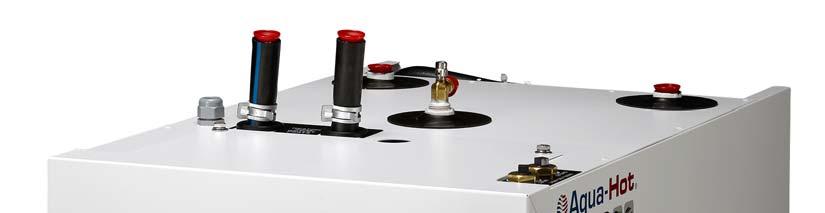
8 SECTION 1: AQUA-HOT HYDRONIC HEATING SYSTEM Figure 3 Heating Zone 1 Outlet Port Heating Zone 2 Outlet Port Wiring Harness and Harness Port AC Terminal Port AC Terminal Block Diesel Fuel Lines VAC Access Panel Diesel Burner Product ID Label Drain Valve Zone 1 Circulation Pump Zone 2 Circulation Pump Diesel Burner Controller Combustion Air Sleeve Interlock Switch Figure 4 Engine Preheat Inlet (From Engine) Engine Preheat Circulation Pump Domestic Cold Water Intlet Engine Preheat Outlet (To Engine) Domestic Hot Water Outlet Page 8

.")

9 SECTION 1: AQUA-HOT HYDRONIC HEATING SYSTEM Figure 5 Zone 1 and 2 Inlet Ports Air Release Valve Expansion Tank Connection WARNING! The Aqua-Hot tank and heating loop operate at 0.0 psi (zero pressure system). Air pressure applied to the tank MUST NOT exceed 20 psi. Excess pressure will result in internal damage. Product ID Label AC Wiring Port Wiring Harness Port Zone 1 and 2 Outlet Ports Diesel Fuel Inlet/Outlet Ports Page 9


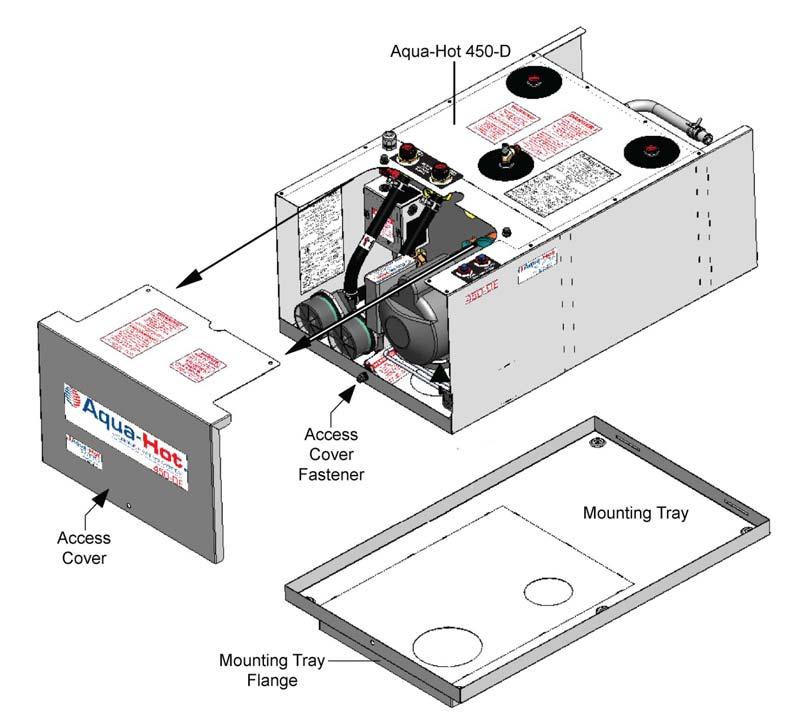
10 SECTION 2: AQUA-HOT INSTALLATION Installing the Mounting Tray and the Aqua-Hot: The Aqua-Hot must be installed in a compartment that is completely closed-off from living quarters and accessible only from the outdoors. 1. Reference the following illustrations for mounting information: Overall Aqua-Hot dimensions - Figure 7 Mounting tray information - Figure 8 I.D. Label noting the Open Access clearance requirement for the front of the heater - Figure 5 Service access clearances - Figure 6 NOTE: Be sure to complete the following when installing the Aqua-Hot: Inspect the area beneath the mounting location to ensure that no structural members will interfere with the cut-out for the mounting tray. Verify that an adequate support system has been provided for the Aqua-Hot. 4. Insert a #10 machine screw into each of the embossed holes in the mounting tray (total of six required) and tighten to secure the mounting tray to the motor home. NOTE: Secure the mounting tray into place prior to installing the Aqua-Hot. Remove the access cover fastener from the Aqua- Hot prior to installation of the Aqua-Hot into the mounting tray. Mount the Aqua-Hot securely into the mounting tray to ensure that the unit does not move or shift under normal operating conditions 5. Place the Aqua-Hot into the mounting tray. Reference Figure 9. NOTE: Remove the bolt securing the front of the access cover to the mounting tray; this bolt will need to be reinstalled once the total installation procedure is complete. Remove the access cover. 2. Cut out the required mounting tray opening. Reference Figure Install the mounting tray flange into the cut-out opening. Reference Figure 8.. Figure 6 1/2 in 1/2 in Page 10


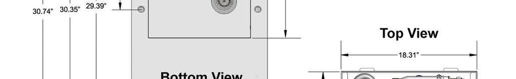
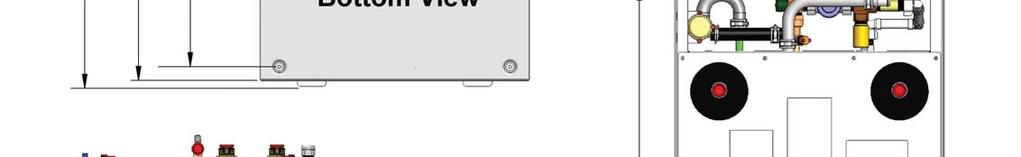
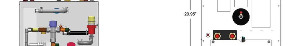
11 SECTION 2: AQUA-HOT INSTALLATION Figure 7 Page 11
12 SECTION 2: AQUA-HOT INSTALLATION Figure 8 Page 12


13 SECTION 2: AQUA-HOT INSTALLATION Figure 9 Page 13

14 SECTION 2: AQUA-HOT INSTALLATION Installing the Expansion Tank: Select a mounting location that allows for easy access and clear visibility whenever the particular storage bay door is open. NOTE: The top of the expansion tank should always be mounted at least 4 inches higher than the highest point on the Aqua-Hot. Reference Figure Mount the expansion tank as illustrated in Figure Connect and clamp the overflow tubing from the expansion tank to the Aqua-Hot s expansion tank connection. Reference Figure 10. NOTE: Avoid any dips and bends in the overflow tubing from the Aqua-Hot to the expansion tank as air can become trapped in these dips and bends, preventing the expansion of the heating solution from properly depositing in the expansion tank. Pressure Testing the Aqua-Hot Tank CAUTION: The Aqua-Hot tank and heating loop operate at 0.0 psi (zero pressure system). Air pressure applied to the tank MUST NOT exceed 20 psi. Excess pressure will result in internal damage. 3. Drill a hole in the bay floor and connect (secure with a clamp) a long enough piece of overflow tubing so that it can be connected to the top of the expansion tank and extend through the bay floor. Figure 10 Expansion Tank Connection Page 14

15 SECTION 3: HYDRONIC HEATING SYSTEM Heat Exchanger Locations and Clearances: Place the heat exchangers so that even heat distribution will be felt throughout the interior of the motor home. Reference Figure 15A. NOTE: For single slide-out configurations, it is usually simplest to place a heat exchanger on the opposite side of the motor home pointing towards the slide-out. Place the heat exchangers where they will be accessible for potential servicing and cleaning. Centralize and position a heat exchanger in the fresh water storage tank plumbing bay. Reference Figure 13. NOTE: In order to achieve the best heating results, place the heat exchanger as close to the floor of the plumbing bay as possible (heat will naturally rise). Reference Figures 14, 15A, 15B, and 16, for mounting location information. Reference Figure 14 for clearance information. NOTE: An accessory device is available for the Cozy Heat Exchanger for the purpose of redirecting the airflow from the heat exchanger. Reference Figures 17 and 18. Mounting Requirements: Sufficient ventilation (return-air) must be supplied to each interior heat exchanger. Reference Figure 16. NOTE: Ventilation (return air) must be supplied from the living area. Ventilation (return air) MAY NOT be supplied from the bay area. NOTE: Mounting the heat exchangers without sufficient ventilation will severely reduce their overall heating performance (heat output). In order to provide sufficient ventilation, the return-air registers must be the same size, or larger, than the outlet-air registers. Return-air must be supplied from the corresponding interior heating zones. Figure 14 Figure 13 Page 15
16 SECTION 3: HYDRONIC HEATING SYSTEM Figure 15A Indicates sample mounting locations for the Cozy heat exchangers. Actual placement and quantity vary based on the individual design of the coach. For specific design assistance, contact Aqua-Hot at Figure 15B Page 16


17 SECTION 3: HYDRONIC HEATING SYSTEM Mounting the Heat Exchangers: 1. Cut out a 2.5 inch H x 10 inch W opening for each heat exchanger outlet and cold-air return register. Reference Figure Mount each heat exchanger permanently into place. Reference Figures 20 and Install the hot-air outlet and cold-air return registers. Reference Figure 16. NOTE: Please note that a return-air register may not be required; however, adequate return-air must be provided to each particular heat exchanger. This means that the total cross-sectional area of the return-air opening must be equal to or greater than the crosssectional area of the hot-air outlet opening of the heat exchanger. Figure 17 Figure 16 If the toe-kick areas in the motor home are inadequate to house a heat exchanger for regular installation, a plenum may be used on the heat exchanger, which can be used with a smaller vent as seen in Figure 18. The plenum allows only the desired outlets to be opened by removing the metal insert on the vent. Figure 18 Hose to direct air to vent Cozy Heat Exchanger Plenum Vent installed In toe-kick area Toe Kick Board Page 17
18 SECTION 3: HYDRONIC HEATING SYSTEM Figure 20 Figure 21 Page 18
19 SECTION 3: HYDRONIC HEATING SYSTEM Wiring the Heat Exchangers: 1. Run two 18-gauge wires, red for (+) and black for (-), from each particular heating zone s heat exchanger to the electronic controller. Reference Figure Label the wires indicating the heating zone they pertain to (e.g., Living Room, Bathroom, Bedroom, etc.). 3. Insert all heat exchanger wires into the appropriate terminal/heating zone location on the electronic controller. Reference Figure 22 and Appendix A. 4. Wire all heat exchangers in a zone in-series. Reference Figure 23 and Appendix A. 5. Connect all electronic controller wires to the positive and negative leads of the heat exchanger. Reference Figures 23 and 24. Figure 22 Page 19

20 SECTION 3: HYDRONIC HEATING SYSTEM Figure 23 Figure 22 Figure 24 When wiring the heat exchangers in-parallel, the main 18- gauge wire is split to allow the heat exchanger wires to combine with the main wire to be powered or grounded, respectively. Page 20

 must be plumbed together in-series on Heating Loop 2. Reference Figure 26. Use 5/8 inch I.D.")
21 SECTION 3: HYDRONIC HEATING SYSTEM Plumbing Requirements: Once all heat exchangers have been mounted, formulate a plan for the routing of the plumbing lines from each heating zone to the Aqua-Hot. All plumbing lines should be laid as flat as possible, and any extreme rises in height should be avoided to eliminate any potential air-traps. The kitchen and living room heat exchangers (typically three) must be plumbed together in-series on Heating Loop 1. Reference Figure 26. The fresh water tank, bedroom, and bathroom heat exchangers (typically 3) must be plumbed together in-series on Heating Loop 2. Reference Figure 26. Use 5/8 inch I.D. (Inside Diameter) plumbing lines for both heating loops. Use wide-sweeping elbows or bend supports whenever the plumbing lines may be susceptible to kinking (i.e., 90 bends). Figure 26 Page 21

22 SECTION 3: HYDRONIC HEATING SYSTEM Plumbing the Hydronic Heating System: 1. Lay out the plumbing lines for all heat exchangers. 2. Label each line with the heating loop number and designate as an inlet or an outlet line. NOTE: Run all plumbing lines in areas where they cannot be pinched off or damaged under normal operating conditions. Be sure to secure all lines where necessary and apply protective shielding in areas where chafing may occur. Rubber Coated/Closed-Type clamps are recommended when securing the plumbing lines. 3. Connect and clamp the outlet line from the heater to the lowest port on the heat exchanger with the longest run, for both heating loops. Reference Figure 27. Then, connect each additional heat exchanger in the same arrangement (low to high). 4. Connect and clamp the inlet line from the heater to the highest port on the last heat exchanger for both heating NOTE: Reference Figure 28 for visual instructions on connecting PEX-type tubing to each heat exchanger. Plumbing heat exchangers in this manner will allow air to escape naturally. If air is trapped in any heat exchanger, it will significantly reduce the heat exchanger s overall heating performance (heat output). loops. Reference Figure Connect and tighten all interior plumbing lines, outlet and inlet, to the Aqua-Hot s appropriate heating loop ports. Reference Figure 29 and Figure 30. NOTE: The inlet and outlet plumbing lines can be installed with a straight fitting or an elbow fitting. Figure 27 Page 22
23 SECTION 3: HYDRONIC HEATING SYSTEM Figure 28 Figure 29 Inlet Heating Loop Connection Examples Barbed Fittings Components Compression Fitting Components Barb Fittings Components Installed Compression Fittings Components Installed Page 23


24 SECTION 3: HYDRONIC HEATING SYSTEM Figure 30 Outlet Heating Loop Connection Examples Pex Tube 3/4 x 3/4 Barbed Fitting Pex Insert Two Constant Tension Band Clamps Pex Tube Pex Insert 3/4 Heater Hose Constant Tension Clamp Constant Tension Clamps Straight Connection Components 90⁰ Connection Components Straight Connection Components Installed 90⁰ Connection Components Installed Page 24


25 SECTION 4: THERMOSTATS Fresh Water Tank Thermostat Wiring: NOTE: The thermostat is not polarity specific and does not require attention to positive / negative wire attachment. 1. Run two blue, 18-gauge wires from the thermostat s mounting location to the Aqua-Hot s electronic controller. 2. Insert each thermostat wire into the appropriate terminal/heating zone location in the electronic controller. Reference Appendix A and Figure 32. NOTE: It is recommended that the wire numbers in Appendix A be used when installing the Aqua-Hot in order to assist with differentiating between the separate heating zones and to aid service personnel 3. The two wires are to be connected to the 2 terminals on the back of the thermostat by either: Using a spade type crimp connector for the #M4 screw. Removing the screw and keeper, and using a 1/4in fast-on crimp connector. attached Bracket. Mount the bracket to a bay wall using fasteners of your choice. Positioning the Bulb and Capillary Tube The Capillary Tube and Bulb should be close to the bay wall with the Bulb located close the bay floor, in the area requiring heat. Do not: mount the bulb in a drafty area or along the ceiling of the bay. Avoid mounting the fresh water tank thermostat s bulb too close to the bay heat exchanger. Select a location that will ensure even-heat distribution throughout the fresh water storage tank bay compartment in order to prevent the domestic water and plumbing system from freezing. Typically only the bulb of the thermostat needs to be physically mounted in the area requiring heat. Setting the Temperature The recommended temperature setting for the bay thermostat is at the 41 F/5 C mark to prevent freezing. Mounting the Bay Thermostat The selected mounting location should allow for easy operator access. Install only after it has been completely wired. The thermostat installs using two mounting holes in the Figure 31 Thermostat Rear View Mounting Holes Thermostat Front View Capillary Tube Bulb Terminals Page 25
26 SECTION 4: THERMOSTATS Room Thermostat Locations: Select a location that will ensure even-heat throughout each heating zone. Locate each thermostat at approximately chest level, if applicable. NOTE: The selected location should prevent the thermostat from being affected by: drafts or dead spots behind doors and in corners hot or cold air from ducts radiant heat from the sun or appliances heat from concealed pipes and chimneys unheated or uncooled areas such as an outside wall behind the thermostat Room Thermostat Mounting: Once the room thermostat has been wired, permanently mount the thermostat in place. Be sure to then turn OFF both interior room thermostats. Room Thermostat Wiring: 11. Run two 18 gauge wires from each room thermostat mounting location to the Aqua-Hot s electronic controller. Reference Appendix A. NOTE: It is recommended that the wire numbers in Appendix A be used when installing the Aqua-Hot in order to assist with differentiating between the separate heating zones and to aid service personnel with troubleshooting. 2. Insert all room thermostat wires into the corresponding zone number location on the electronic controller. Reference Appendix A and Figure Connect all wires to the appropriate leads of each room thermostat. Figure 32 Page 26
27 SECTION 5: DOMESTIC WATER SYSTEM Domestic Water System Requirements: NOTE: Please note that it may be necessary to utilize an accumulator tank within the domestic water system. Reference Figure 34. Although the Aqua-Hot is equipped with a pressure-relief valve, the use of an accumulator tank will help prevent excessive weeping of the valve. Manufacturers of pressure-relief valves indicate that excessive weeping of these valves will cause the seat in the valve to deteriorate, and, in turn, the valve will fail prematurely. For additional information regarding accumulator tanks, please be sure to reference the Recreational Vehicle Industry Association s (RVIA) technical publication titled Recreational Vehicle Plumbing Systems. To obtain a copy of this particular publication, please contact RVIA at (703) or visit them online at Use the RVIA-provided table below in order to determine the proper sizing of pipe and tubing required to ensure maximum efficiency. The size of water supply piping and branch line shall not be less than specified in the table below. NOTE: As stated directly from the ANSI A119.2/NFPA 501C Standard on Recreation Vehicles, 1993 Edition: Piping Systems shall be sized to provide an adequate quantity of water to each Plumbing Fixture at a flow rate sufficient to keep the Fixture in a clean and sanitary condition without any danger of back-flow or siphoning. The Aqua-Hot is equipped with a pressure-relief valve, which releases excessive pressure in the domestic water system, if necessary, as well as a tempering valve in order to regulate the temperature of the hot water. Domestic Water System Plumbing: 1. Connect a domestic water plumbing line from the domestic water demand pump/water manifold to the cold water inlet port on the Aqua-Hot. Reference Figures 33 and Connect a domestic water plumbing line from the Aqua- Hot s hot water outlet port to the hot water system s distribution lines/water manifold. Reference Figures 33 and 34 NOTE: A water heater or ice maker shall not be counted as a water-using fixture when computing pipe sizes. Page 27


28 SECTION 5: DOMESTIC WATER SYSTEM Figure 33 Tempering Valve Domestic Cold Water Inlet Domestic Hot Water Outlet Figure 34 Page 28
29 Switch Panel Location: 1. Select a location in the interior of the coach that allows for easy operator access. 2. All electric installations, systems, and equipment shall comply with Article 551, Parts I and III through VI of NFPA 70, as well as the regulation of authorities having jurisdiction and CSA Standard B139. Switch Panel Mounting: 1. Cut out a 3.9 W x 1.75 H opening for the switch panel plate. Reference Figure Once the switch panel has been completely wired, permanently mount the switch panel in place. Move both switches to an OFF position by pressing them in a downward motion. SECTION 6: SWITCH PANEL 1. Run 16-gauge wires from the switch panel to the electronic controller. NOTE: Be sure to attach Jumper Wires where necessary. Reference Figure Strip and crimp insulated female terminals onto each wire at the switch panel location. 3. Connect all switch wires to the appropriate switch connections as illustrated in Figure 36. Reference Appendix A for additional wiring information. 4. Insert all switch wires into the appropriate terminal/ switch panel connection on the electronic controller. Reference Appendix A. Reference Appendix A. Switch Panel Wiring: NOTE: It is recommended that the wire colors illustrated in Appendix A be used when installing the switch panels. This will ensure installation consistency, differentiate between the separate switches and assist service personnel with troubleshooting. Reference Appendix B for proper wire-gauge sizing. Figure 35 Page 29
30 SECTION 6: SWITCH PANEL Figure 36 Aqua-Hot 450D Interior Switch Panel Rear View Engine Preheat Switch Electric Element Switch Diesel Burner Switch Jumper Wire 2 Jumper Wire Switch Pin# 2 Pin# 4 Pin# 9 Electronic Controller To Preheat-O To Preheat-I To Chassis Ground Engine Preheat Switch to Electronic Controller connections Switch Pin# 2 Pin# 4 Pin# 9 Electronic Controller To Electric-O To Electric-I To Chassis Ground Switch Pin# 2 Pin# 4 Pin# 10 Pin# 9 Electronic Controller To Diesel-I To Diesel-O To IND-LT (+) B3 To IND-LT (-) B6 Diesel Burner Switch to Electronic Controller connections Electric Element Switch to Electronic Controller connections NOTE: The engine preheat and electric element switches possess jumper wires, which advance from terminal 10 to terminal 4. Page 30


31 SECTION 7: FUEL SYSTEM A kinked fuel line (return side) will increase the fuel pressure to hazardous levels and may cause a fuel line to rupture. A kinked fuel line could also severely damage the diesel-burner s internal fuel system. Fuel Filter Location: CAUTION: Mount the fuel filter assembly in a location that provides easy access for replacing the filter element and for catching any potential fuel spillage when servicing. Fuel System Requirements: The diesel fuel supply should be drawn directly from the vehicle s main fuel tank or from a separate auxiliary fuel tank, if applicable. The fuel tank should be equipped with a dedicated fuel pick-up pipe (outlet port and inlet port). Reference Figure 38. NOTE: If an auxiliary fuel tank is required, be sure to consult the ANSI/NFPA 1192 handbook concerning heating systems diesel fuel system specifications. Also, be sure to reference the ANSI/NFPA 1192 handbook for information regarding fuel distribution system specifications. Use 1/4 inch I.D. (Internal Diameter) fuel lines. The combined length of the supply and return fuel lines should not exceed 100 feet in total length. Reference Figures 39. All fuel-fitting hardware (i.e., at the vehicle s fuel tank, fuel filter, and Aqua-Hot fuel parts) must be 1/4 inch NPT or greater with a 1/4 inch barbed fitting. Fuel fittings less than 1/4 inch NPT may restrict fuel flow, thereby compromising the diesel-burner s performance. Fuel System Installation: 1. Run two 1/4 inch fuel lines from the fuel tank inlet and outlet ports to the Aqua-Hot. Both fuel lines should be laid as flat as possible and any extreme rises in height should be avoided in order to eliminate any potential air-traps. Run both fuel lines in areas where they cannot be pinched, kinked, or damaged during normal operating conditions. Run the fuel tank outlet fuel line past the fuel filter location in preparation for step Be sure to secure all fuel lines where necessary and apply protective shielding in areas where chafing may occur. 3. Label both fuel lines indicating whether they are an outgoing line or an incoming line. 4. Connect the Aqua-Hot s fuel lines to the vehicle s fuel tank. Reference Figure Install and tighten the appropriate fuel fittings onto the Aqua-Hot s fuel ports, as well as the two ports of the fuel filter. Reference Figures Connect the inlet and outlet fuel lines to the Aqua- Hot s fuel port connections. Reference Figure Cut the fuel line at the fuel filter mounting location and connect the fuel lines as illustrated in Figures 40. NOTE: Be sure that the flow of fuel through the filter is in the correction direction as illustrated in Figure 40. Figure 38 Page 31
32 SECTION 7: FUEL SYSTEM Figure 39 Page 32
33 SECTION 7: FUEL SYSTEM Figure 40 Reference Figure 41 Reference Figure 38 Figure 41 1/4 NPT (F) Diesel Outlet Port 1/4 NPT (F) Diesel Inlet Port Page 33
34 SECTION 8: ENGINE PREHEAT & MOTORAIDE SYSTEM Engine Preheat and Motoraide System: Location: The Aqua-Hot 450-D includes a motoraide feature, which uses the circulation of the motor home s engine to transport the antifreeze and water heating solution from the Aqua-Hot s boiler tank to the motor home s warm engine and back to the boiler tank. The Aqua-Hot 450-D also includes an engine preheat feature. This preheat feature provides an easy engine start-up whenever cool weather conditions are present. Secure both plumbing lines where necessary and apply protective shielding in areas where chafing may occur. NOTE: Rubber coated/closed-type clamps are recommended when securing the plumbing lines. Use one-piece engine plumbing fittings in order to reduce the potential for coolant leaks. It is recommended that pipe thread sealant be used on all engine plumbing fittings. Installing the Plumbing: The inlet and outlet ports on the vehicle s engine should be kept as far apart as possible. This will ensure that the entire engine is thoroughly preheated. Reference Figure 42. NOTE: If assistance is needed in determining the best inlet and outlet ports for a specific engine, please contact the particular engine s manufacturer or chassis supplier. The engine s coolant should be allowed to flow as freely as possible to maximize the Aqua-Hot s engine preheating system. The engine s inlet port is where the heated coolant is transported to the engine block from the Aqua-Hot. This port should be a high connection point on the engine block. Reference Figure 42. The engine s outlet port is where the engine s coolant is transported to the Aqua-Hot. This port should be a low connection point on the engine block or a pressure outlet port on the engine s water pump. Reference Figure 42. Ensure that the engine preheat inlet and outlet hoses are not placed too close to the engine s turbo charger. Plumbing Requirements: Use ¾ inch I.D. (Inside Diameter) plumbing lines/ automotive-type heater-hose for the engine preheating system. Lay both engine preheat lines as flat as possible and avoid any extreme rises in height in order to eliminate the potential for air traps. Run both plumbing lines in areas where they cannot be pinched off or damaged during normal operating conditions. 1. Install both engine preheat plumbing lines and mark with arrows and/or labels at both ends. NOTE: The labels should indicate whether the plumbing line is transporting coolant to the Aqua-Hot or whether it will be transporting heated coolant to the vehicle s engine. Reference Figure Drain the engine s coolant. 3. Remove the selected inlet and outlet port plugs from the engine. NOTE: Should one or both of the selected engine ports already have plumbing fittings attached to them, it may be necessary to tee into those existing plumbing fittings. Please contact the Aqua-Hot Heating Systems product application department at for additional assistance. 4. Install and tighten the plumbing fittings into the inlet and outlet ports on the vehicle s engine. 5. Install and clamp both the inlet and outlet engine plumbing lines/automotive-type heater hoses to the engine s plumbing fittings. Reference Figure Install and tighten a plumbing fitting into the Inlet port on the Aqua-Hot s engine preheating system. Reference Figures 1 and Attach and clamp the engine s incoming plumbing line to the Aqua-Hot s outlet connection. Reference Figure Attach and clamp the engine s outgoing plumbing line to the Aqua-Hot s inlet connection. Reference Figure Verify that all fittings and connections have been tightened, then refill the engine s coolant system. Page 34
35 Figure 42 SECTION 8: ENGINE PREHEAT & MOTORAIDE SYSTEM Figure 43 Engine Preheat Inlet Engine Preheat Circulation Pump Engine Preheat Outlet Page 35
36 SECTION 9: EXHAUST SYSTEM The Aqua-Hot s exhaust is hot and must be kept away from any heat-sensitive material. DO NOT direct exhaust downward as a fire may result when parked in dry, grassy areas. Exhaust must not terminate beneath the vehicle or beneath an open able window or vent. DO NOT terminate the exhaust pipe within the awning area of the motor home, if applicable. Be sure to keep the exhaust away from the slide-out areas. All Aqua-Hot exhaust system installations MUST utilize the two black pipe nipples and the black pipe elbow, which are provided with the heating system, in the configuration best suited for the particular recreational vehicle application. Failure to conform could create a hazardous situation and will void the Aqua-Hot s ETL product listing. NOTE: Refer to Internal Combustion Engine Exhausts and Vehicle Wall Openings in RVIA s ANSI/NFPA 1192 Handbook for the Recreational Vehicle Standards, as well as the National Fire Protection Association s (NFPA) 1192 Standard on Recreational Vehicles for additional information. Exhaust System Requirements: The exhaust must be able to freely exit away from the vehicle without any obstructions. Angle the exhaust pipe towards the rear of the vehicle so that the exhaust fumes will naturally move away while the vehicle is in motion. Reference Figure 45. Do not use galvanized pipe or fittings; only black -iron pipe and fittings should be used. Reference Figure 47. The total length of exhaust pipe should not exceed 27.5 feet. The Aqua-Hot is supplied with a 3 inch and a 4 inch black pipe nipple (1½ inch diameter) along with a 1½ inch exhaust elbow. Reference Figure 45. These three exhaust system components MUST BE utilized with all product installations. Be sure to reference Figure 46 and 47 to determine which exhaust nipple should be connected directly to the Aqua-Hot s exhaust port (i.e., the 3 inch or the 4 inch black pipe nipple). NOTE: Should the particular application require more than 27.5 feet of exhaust pipe, please contact the Aqua-Hot Heating Systems Product Application Department at for assistance. Installing the Exhaust System: 1. Run the exhaust pipe to the driver s side or the back of the vehicle and ensure that the exhaust fumes cannot enter into the passenger compartment. Be sure to keep the exhaust away from the slide-out areas. 2. Be sure to secure the end of the exhaust pipe to the vehicle with the proper exhaust hanger/ support hardware. Use standard 2 inch automotive-type exhaust piping and avoid bends, if possible. A minimum 1.75 ID automotive-type exhaust pipe may be used. Reference Figures 44 and 47. A maximum of three 90º exhaust pipe bends are allowed. Reference Figure 44. Page 36


37 SECTION 9: EXHAUST SYSTEM Figure NOTE: A maximum of 27.5 feet with three 90⁰ bends are allowed in the exhaust pipe. A minimum of 1.75 ID automotive type exhaust pipe may be used. Figure 45 Page 37


38 SECTION 9: EXHAUST SYSTEM Figure 46 Page 38


39 SECTION 9: EXHAUST SYSTEM Figure 47 3 Black Pipe Nipple Installed Black Pipe Elbow 4 Black Pipe Nipple Installed 2 Automotive Type Exhaust Pipe Page 39
40 SECTION 10: ELECTRONIC CONTROLLER WIRING Electronic Controller Wiring: NOTE: Please reference Appendix A for specific wiring information. NOTE: A maximum power consumption of 24 Watts can be supplied by the electronic controller for each FAN heating zone. Most electronic controller thermostat and switch connections possess an (I) or an (O) symbol. The (O) symbol incates a positive 12 Volt-DC output to a particular thermostat or switch, while the (I) symbol indicates a positive 12 Volt-DC input signal from a particular thermostat or switch. The 12Volt DC output signal is always present as long as the electronic controller is powered by a 12 Volt-DC power source, while the 12 Volt-DC input signal is only present whenever a switch is activated or whenever a thermostat is calling for heat. Reference Appendix A. All electronic controller fan power connections (and two switch connections illustrate a (+) or a (-) symbol, which indcates that they are polarity-sensitive. Therefore, be sure to use care when wiring these particular components to the electronic controller. Each heating zone FAN circuit can supply up to 2.0 Amps of direct current. This 12 Volt-DC power source allows for Multiple Cozy III heat exchangers to be wired in-parallel. ReferenceFigure 44 and Appendix A. Heating Zone 1 is reserved electrically for the Living Room/ Kitchen Heating Zone (Heating Loop 1) ONLY, and Heating Zones 2, 3, and 4 are reserved electrically for the Bathroom, Fresh Water Tank, and Bedroom Heating Zone (Heating Loop 2) ONLY. Heating Zone 5 is reserved electrically for the Optional Heating Zone (Heating Loop 1) ONLY. All switch connections are to be wired directly to the Aqua-Hot s interior switch panel. Reference Figures 36 and Appendix A. Both the IND-LT (+) B3 and the IND-LT(-) B6 connections on the electronic controller are reserved electrically ONLY for the diesel-burner switch indicator light connections. The Aqua-Hot s electronic controller is designed to work with most electronic room thermostats; however, the chosen thermostat must produce a constant 12 Volt-DC output signal and must receive its 12 Volt-DC power supply from the electronic controller (i.e., THERM-O ) in order to ensure that the thermostat and electronic controller are properly fuse protected Figure 48 Page 40
 by incorporating a 20-Amp rated inline fuse into the power wire at the battery location.")


41 SECTION 10: ELECTRONIC CONTROLLER WIRING CAUTION: Be sure to protect against accidental shorting (i.e., chassis shorting) by incorporating a 20-Amp rated inline fuse into the power wire at the battery location. Reference Figure 50. DO NOT activate the diesel-burner until the antifreeze and water heating solution has been added to the boiler tank and the heating system has been completely bled of air. Operating the Aqua-Hot without the antifreeze and water heating solution will cause serious damage to the AquaHot s boiler tank. All electric installations, systems, and equipment shall comply with Article 551, Parts I and III through VI of NFPA 70, as well as the regulation of authorities having jurisdiction and CSA Standard B139. WARNING DO NOT connect the 12 Volt-DC power to the Aqua-Hot if the vehicle requires welding. Electrical welding will cause serious damage to the diesel-burner controller and the AquaHot s electronic controller. NOTE: Reference Appendix B for proper wire-gauge sizing. Please note that under full-load conditions, the AquaHot can draw as much as 20 Amps of DC current. Wiring Harness Connection: Attach wiring harness connectors to the electronic controller. Reference Figures 48 and 49 and Appendix A. Tighten the screw-type fasteners Because the Aqua-Hot is designed to shut down in the event that the DC voltage level drops too low to properly operate, it is imperative that the proper wire e be determined and utilized. Connect corresponding 9 and 16 pin connectors from wiring harness Figure 49 Wiring Harness Connectors Page Aqua-Hot 450-D Installation Manual


 wire and one black (-) wire (power and ground), from the vehicle s main battery disconnect to the Aqua-Hot s electronic controller.")
42 SECTION 10: ELECTRONIC CONTROLLER WIRING Connecting the 12 Volt-DC Power: Figure 51 CAUTION: DO NOT connect the 12 Volt-DC power to the Aqua-Hot if the vehicle requires welding. Electrical welding will cause serious damage to the diesel-burner controller. The Aqua-Hot is designed to shut down in the event that the DC voltage level drops too low to properly operate, it is imperative that the proper wire gauge be determined and utilized. Reference Appendix B for proper wire-gauge sizing. Please note that under fullload conditions, the Aqua-Hot can draw as much as 20 amps of DC current. Be sure to protect against accidental shorting (i.e., chassis shorting) by incorporating a 20-Amp rated inline fuse into the power wire at the battery location. Reference Figure Run and connect two wires one red (+) wire and one black (-) wire (power and ground), from the vehicle s main battery disconnect to the Aqua-Hot s electronic controller. Reference Appendix A and Figure Label the wires indicating whether they are a power or a ground wire. 3. Attach the VDC power wires onto the appropriate terminal/battery connections on the electronic controller. Reference Appendix A. 4. Connect both power and ground wires to the vehicle s batteries through the vehicle s main battery disconnect. DO NOT activate the diesel-burner until the antifreeze and water heating solution has been added to the boiler tank and the heating system has been completely bled of air. Operating the Aqua-Hot without the antifreeze and water heating solution will cause serious damage to the Aqua- Hot s boiler tank. Connecting the 120 Volt-AC Power: 1. Route and insert three 120 VAC power source wires into the AC terminal block through the AC wiring port s cable clamp fitting and into the proper terminal. Reference Appendix A and Figure Secure the wires into their terminals by tightening the corresponding screw on the terminal block to 5 inchpounds using a slotted screw driver blade no larger than 1/8. Reference Figure 50. Figure 50 AC Wiring Port AC Terminal Block WARNING NOTE: A ferrule is required if stranded wire is being used to connect to the terminal block Main Battery Disconnect Page 42

43 SECTION 11: PURGING THE SYSTEMS Only propylene glycol based boiler type antifreeze deemed GRAS (Generally Recognized as Safe) by the FDA shall be used in the Aqua-Hot s hydronic heating system. Failure to use the above specified antifreeze type could result in serious injury or death. Ensure that the overflow tube is connected from the Aqua- Hot s expansion tank connection to the expansion tank s bottom connection and from the expansion tank s top connection through the overflow tube hole in the motor home s bay floor prior to beginning this antifreeze and water heating solution fill procedure. Failure to do so could result in an antifreeze spill in the motor home s bay. Reference Figure 10. Figure 52 WARNING CAUTION: Purging the Hydronic Heating System: In order to provide the best freeze protection, boil-over protection, and anti-corrosion and rust protection, a 50/50 mixture of GRAS approved propylene glycol antifreeze and water is recommended. Reference Appendices C through E for additional information regarding the antifreeze and water heating solution. Be sure to use a GRAS boiler-type propylene glycol based antifreeze rather than an RV and Marine antifreeze or an automotive antifreeze/coolant. If assistance is needed in selecting an appropriate antifreeze, please contact the Aqua-Hot Heating Systems Product Application Department at Open the Aqua-Hot s drain valve located at the front of the heater. Reference Figure Connect a piece of 1/2 inch PEX-type tubing to the drain valve. This piece should be long enough to transport the antifreeze and water heating solution from its source to the Aqua-Hot. Figure 53 NOTE: The Aqua-Hot s boiler tank must be filled with the antifreeze and water heating solution through the drain valve and not through the top of the unit, in order to avoid air traps. Reference Figure 53. Drain Valve Page 43
44 SECTION 10: PURGING THE SYSTEMS 3. Fill the Aqua-Hot completely with the 50/50 mixture of antifreeze and water heating solution. This will take approximately five gallons; look for the solution to enter the overflow tube attached to the expansion tank connection on top of the Aqua-Hot. 4. When refilling, open the air-release valve located on the expansion tank connection to release air pockets. Reference Figure 52. Hold the valve open until all air is released. Be sure the valve is closed when finished by hand-tightening. Look for the solution to enter the overflow tube attached to the expansion tank connection on top of the Aqua-Hot. 5. Close the drain valve. Purging the System by Grounding the Zone Thermostat Connection: 1. Ensure that the boiler tank has been filled with the appropriate 50/50 mixture of antifreeze and water heating solution. 2. Locate the heating zone circulation pumps. Reference Figure Take the circulation pump s blue (negative) wire and disconnect it from the connector of the opposing wire. Reference Appendix A. 4. Connect an alligator clip to the spade terminal on the circulation pump s blue (negative) wire and clip the opposite end of the cable to a ground source. 7. Repeat steps 5 and 6 for both heating loops until all air has been completely bled from the entire heating system. NOTE: All air is bled from the heating system when both plumbing lines are free of air. Reference Figure Once the systems have been purged, disconnect the alligator clips from the ground source and the circulation pump s wires. Reconnect the pump s wires as originally configured. Reference Figure Check the Aqua-Hot s expansion tank and top it off to the cold level mark with the 50/50 antifreeze and water mixture, if necessary. 10. Ensure that each circulation pump s wiring has been returned to its original configuration. Reference Figure 54. Purging the Domestic Water System: Verify that the domestic water tank contains fresh water prior to bleeding the fresh water system. 1. Ensure that the vehicle s domestic water pump has 12 Volt-DC power, then activate it by opening each hot water faucet, one at a time, and running the water until all air is purged from the domestic water system. 2. Once the domestic water system is completely bled, check for leaks in the domestic water system. NOTE: The circulation pump will activate as soon as the pump is connected to a ground source; therefore, disconnect the alligator clip from the ground source during the antifreeze and water heating solution filling procedure. 5. Allow the circulation pump to operate for approximately 1-3 minutes in order to purge the corresponding heating loop, then remove the alligator clip from the ground source. 6. Open the drain valve and completely fill the Aqua-Hot s boiler tank with additional antifreeze and water heating solution. Page 44
45 SECTION 10: PURGING THE SYSTEMS Figure 54 Zone 1 Circulation Pump Zone 2 Circulation Pump Page 45
46 SECTION 12: INITIAL START-UP Activating the Aqua-Hot: 1. Reinstall the Aqua-Hot s main access cover and the fastener, which secures the front of the Aqua-Hot s access cover to the mounting tray. NOTE: The main access cover must be installed prior to operation; a safety switch exists, which will prevent the Aqua-Hot from operating whenever the main access cover is not properly installed. 2. Move the diesel burner switch to the ON position for approximately ten seconds ONLY, then switch it OFF. NOTE: This procedure will purge the diesel-burner s fuel system by allowing the heater s fuel pump to complete its normal second shutdown/purge cycle. 3. After the purge cycle has ended, repeat once more. 4. Move the diesel-burner switch to the ON position and leave it on in order to activate the diesel-burner. NOTE: It will take approximately 10 seconds before the diesel -burner will ignite and exhaust can be heard exiting the heater. Allow approximately minutes for the Aqua-Hot to reach normal operating temperature (approximately 190 F). 5. Move the Aqua-Hot s electric element switch to the ON position in order to supply 120 Volt-AC power to the electric heating element. NOTE: Both the 12 Volt-DC powered diesel-burner and the electric heating element are thermostatically controlled. Either or both heating sources will automatically maintain the temperature of the boiler tank s antifreeze and water heating solution. The Aqua-Hot is now ready for normal operation and use. Page 46
47 APPENDIX A: WIRING DIAGRAM Page 47
48 APPENDIX B: WIRE GAUGE INFORMATION Page 48

49 Secondary 12 Volt-DC Battery Connection: APPENDIX C: ELECTRONIC CONTROLLER FEATURES The electronic controller is equipped with two 12 Volt-DC power source connections, which allow for a secondary 12 Volt-DC battery connection. This 12 Volt-DC battery connection is a product-safety feature that should be utilized whenever the Aqua-Hot s main 12 Volt-DC power supply is connected to a battery disconnect switch. This feature will ensure that the Aqua-Hot will be protected in the event that the primary power is interrupted while the Diesel-Burner is operating (e.g., during a burn-cycle). This secondary 12 Volt-DC battery connection will ensure completion of the required 3-minute purge cycle of the Aqua-Hot s diesel-burner. Terminals Strips with Screw-Type Fasteners: The electronic controller utilizes terminal strips/plugs that are equipped with screw-type fasteners, which are molded directly into the terminal strip/plug, itself. This will ensure a positive mechanical connection between the electronic controller and all wire harnesses attached to it. Page 49

50 APPENDIX C: ELECTRONIC CONTROLLER FEATURES Low Voltage Reset Feature: Whenever the Aqua-Hot s DC power is interrupted, the low voltage reset red indicator light on the electronic controller will illuminate. Reset the electronic controller by pressing the low voltage reset button on the electronic controller (use a thin, straight, nonmetallic object to access the button through the faceplate) or by turning OFF the diesel-burner switch on the interior switch panel for approximately 30 seconds, then turning the switch back ON. Page 50
51 APPENDIX D: ANTIFREEZE TYPES The following information addresses the necessary usage of a propylene glycol based boiler type antifreeze in the Aqua -Hot. Propylene glycol is a safer alternative to the more toxic ethylene glycol antifreeze; however, as mandated by IAPMO (International Association of Plumbing and Mechanical Officials), only those propylene glycol based boiler type antifreezes deemed Generally Recognized as Safe (GRAS) by the FDA should be utilized. Because of the significant impact various types of antifreeze can have on a hydronic heating system, including the level of safety provided, it has been recognized that there is a need to provide an explanation regarding two additional prominent types of antifreeze/coolant available. The following information should be utilized as an educational means of ensuring that the proper type of propylene glycol based antifreeze is selected: RV & Marine Antifreeze: These types of propylene glycol based antifreeze products are formulated specifically for winterizing applications only. Although RV & Marine antifreeze is often Generally Recognized as Safe by the FDA, it should never be used in the Aqua-Hot s Hydronic Heating System. This type of antifreeze is not formulated to transfer heat, which is essential to the heating system s functionality and does not contain rust inhibitors. Please note, however, that RV & Marine antifreeze can be utilized to winterize the Aqua-Hot s Domestic Hot Water Heating System. Automotive Antifreeze/Coolant: These types of propylene glycol based antifreeze products are formulated specifically to protect automotive engines against corrosion, freezing temperatures, and overheating. They also have excellent heat transfer and thermal conductivity characteristics. Although these types of antifreeze products are considered less toxic and safer than ethylene glycol for people, pets, and the environment, they are not Generally Recognized as Safe (GRAS) rated by the FDA. Therefore, they must be marked with a harmful if swallowed warning. This additional warning is required because these types of antifreeze products contain high levels of chemical rust inhibitors. Due to their potentially hazardous properties, they should never be used in the Aqua-Hot s Hydronic Heating System. APPENDIX E: ANTIFREEZE MIXTURE WATER QUALITY RECOMMENDATIONS In order to ensure maximum performance and longevity of an Aqua-Hot heating system s boiler tank and associated components, it has been determined that there is a need to use distilled, de-ionized, or soft water in combination with concentrated propylene glycol for the Aqua-Hot s antifreeze and water heating solution. Please note that this is only necessary when mixing concentrated propylene glycol antifreeze with water; suppliers of pre-mixed antifreeze are responsible for the use of high-quality (distilled, de-ionized, or soft) water when preparing their antifreeze for sale. Hard water possesses a high-level of calcium and magnesium ions, which deplete the propylene glycol antifreeze s corrosion inhibitors. This, in turn, causes the antifreeze and water heating solution to begin turning acidic, which can corrode the Aqua-Hot s Boiler tank and associated components prematurely. Therefore, concentrated propylene glycol should be diluted with distilled, de-ionized, or soft water which is 80 ppm or less in total hardness. The local water agency should have up-to-date water quality reports which should indicate if the local tap water is within this guideline. Page 51
52 APPENDIX F: ANTIFREEZE TERMS AND MIXTURE RATIO Propylene Glycol Based Antifreeze Solution: The following information addresses the process of selecting a propylene glycol based antifreeze solution that provides adequate freeze, boiling, and rust/anti-corrosive protection. A propylene glycol antifreeze solution that is 35% to 50% propylene glycol is recommended. Antifreeze solution with 50% propylene glycol will result in a freeze point of approximately -28ºF and a boil point of approximately 222ºF. NOTE: As the installer of this Aqua-Hot system, you must refer to the information and chart in Appendix E to determine the percentage of propylene glycol your antifreeze solution should contain for the level of protection you require. Aqua-Hot sells CAMCO propylene glycol based antifreeze solution in the following packages: Part Number Container Size % Propylene Glycol MSX Gallon Bottle 68% MSX Quart Bottle 98% MSX Gallon Drum 68% NOTE: Propylene glycol based antifreeze solution is not 100% propylene glycol. It is a mixture of propylene glycol, rust and anti-corrosive inhibitors, and water. The following information should be utilized for the purpose of clarifying some terms commonly associated with antifreeze. Freeze Point and Burst Point: Antifreeze solution lowers the freezing point of any liquid, to which it has been added, by preventing the formation of ice crystals; however, as the ambient temperature continues to decline, the water in the solution will attempt to attain a solid state. The point in which the water begins to solidify is termed the Freeze Point. Although the water in the solution has begun to freeze, producing a slushy consistency, the antifreeze in the solution will continue to combat the normal expansion of the solution as it freezes. The point in which the solution can begin to expand, due to colder temperatures, is called the Burst Point. Once the solution reaches the burst point, the potential is present for ruptured pipes to exist. The burst point of the antifreeze and water heating solution is dependent upon the brand of propylene glycol antifreeze employed. Page 52 Boiling Point: The Aqua-Hot utilizes the propylene glycol based (PPG) antifreeze and water heating solution as a transportation means for the heat produced from the internal processes. The PPG antifreeze solution absorbs the heat created until its boiling point is reached; it is at this point that the liquid turns to a gas and is expelled to prevent the heating system from overheating. Each time the boiling point is reached, a loss of efficiency occurs because the heat produced is expelled rather than utilized for the function of the heating system. Therefore, a higher boiling point is desired in order to combat the loss of efficiency, which allows the antifreeze to transport the heat created from the internal process throughout the motorhome where it can be utilized productively rather than dissipating due to its change from a liquid to a gas. Rust and Anti-Corrosive Inhibitors: Another major function of antifreeze solution is to provide protection to the internal metal components of the Aqua-Hot hydronic heating system from corrosion and rust. Antifreeze is able to perform this function by the addition of rust and anti-corrosive inhibitors, which are designed specifically to activate in a water solution. Summary: Antifreeze solution has three basic functions: freeze protection, boil-over protection, and anti-corrosion and rust protection. PPG Antifreeze solution is also primarily responsible for heat transfer; however, propylene glycol itself does not possess acceptable heat transfer characteristics. Therefore, as water is an excellent heat conductor, it is added to the mixture. PPG antifreeze solution, mixed with water, that is 35% to 50% propylene glycol is recommended to provide the best performance combination of the aforementioned functions. If excess propylene glycol exists within an antifreeze and water heating solution, the water s heat absorption properties are compromised, which could ultimately inhibit the Aqua- Hot from providing adequate domestic hot water and interior heating. Additionally, if the antifreeze and water heating solution contains over 70 percent propylene glycol, the freezing point is actually raised, resulting in less freeze protection. Please reference the attached graphical representation regarding the percentage of antifreeze to water and how it directly affects the solution s freezing point.

53 APPENDIX F: ANTIFREEZE TERMS AND MIXTURE RATIO Page 53

54 APPENDIX G: MEASURING PROPYLENE GLYCOL USING A REFRACTOMETER CALIBRATE THE REFRACTOMETER Aqua-Hot Part Number MSX Figure 1 Calibration Screw Eyepiece Daylight Plate Assembly Main Prism Assembly
INSTALLATION MANUAL Aqua-Hot Heating Systems Inc.
 INSTALLATION MANUAL 2011 Aqua-Hot Heating Systems Inc. CAUTION: The Aqua-Hot tank and heating loop operate at 0.0 psi (zero pressure system). Air pressure applied to the tank MUST NOT exceed 20 psi. Excess
Installation Manual Aqua-Hot Heating Systems Inc.
 Installation Manual 2008 Aqua-Hot Heating Systems Inc. Table of Contents Aqua-Hot 375-D Installation Manual Introduction...1 Section 1: Aqua-Hot Hydronic Heating System Technical Information...2 Section
Installation Manual East Highway 52 Fort Lupton, Colorado Fax:
 Installation Manual 15549 East Highway 52 Fort Lupton, Colorado 80621 1.800.685.4298 Fax: 303.857.9000 www.aqua-hot.com LTE-907-713 Contents General Information Introduction.....................................
SERVICE MANUAL AHE-375-P Aqua-Hot Heating Systems Inc.
 WARNING: If the information in these instructions is not followed exactly, a fire or explosion may result causing property damage, personal injury, or death. Do not store or use gasoline or other flammable
SERVICE MANUAL 400SERIES AHE-400-P01
 SERVICE MANUAL 400SERIES AHE-400-P01 Warning Labels Caution Notes As you read this Information, take particular note of the NOTICE, CAUTION, WARNING and DANGER symbols when they appear. This information
USE & CARE GUIDE 400SERIES 400P
 USE & CARE GUIDE 400SERIES 400P Journey in Comfort Thank you for equipping your RV with an Aqua-Hot hydronic heating system! We value your business and are grateful for the trust you have placed with Aqua-Hot
- 12 VDC. HHE M - 12 VDC.
 R OWNER S MANUAL Model Number HHE-200-09E - 12 VDC. HHE-500-09M - 12 VDC. OWNER S INFORMATION Owner s Name: Address: City: State: Zip Code: CUT HERE AND MAIL IN Telephone: E-mail Address: Motorhome Model:
USE & CARE GUIDE 400SERIES 400-D
 USE & CARE GUIDE 400SERIES 400-D Journey in Comfort Thank you for equipping your RV with an Aqua-Hot hydronic heating system! We value your business and are grateful for the trust you have placed with
AHE S -12 VDC AHE S - 24 VDC
 Owner s Manual Model Numbers AHE-100-02S -12 VDC AHE-200-02S - 24 VDC OWNER S INFORMATION Owner s Name: Address: City: State: Zip Code: CUT HERE AND MAIL IN Telephone: Coach Model: Coach Date of Purchase:
OASIS NE Heating System
 OASIS NE Heating System Installation and Operating Manual Diesel and AC Heating System for Recreational Vehicles and Yachts CAN/CSA-C22.2 No.110-94 (R2014) CSA B140.10-06 (R2015), CSA B140.0-03 (R2013)
OASIS Heating System. Installation and. Operating Manual. Diesel and AC Heating System for Recreational Vehicles and Yachts
 OASIS Heating System Installation and Operating Manual Diesel and AC Heating System for Recreational Vehicles and Yachts CSA TIL R-17 ANSI/UL307A CAN/CSA-C22.2 No.165 Copyright January 2011, Revised August
OASIS NE-S Heating System
 OASIS NE-S Heating System Installation and Operating Manual Diesel and AC Heating System for Recreational Vehicles and Yachts CAN/CSA-C22.2 No.110-94 (R2014) CSA B140.10-06 (R2015), CSA B140.0-03 (R2013)
Seaward Products OWNER S MANUAL WATER HEATERS. Serial Number:
 Seaward Products WATER HEATERS OWNER S MANUAL Serial Number: IMPORTANT SAFETY INSTRUCTIONS WARNING When using electrical appliances, basic safety precautions to reduce the risk of fire, electrical shock,
Installation Requirements for Models:
 900 & 9100 Series Refrigerators Installation Requirements for Models: 9162 9163 9182 9183 962 963 982 983 WARNING Improper installation, adjustment, alteration, service, or maintenance can cause injury
SECTION AUXILIARY HEATER
 14-301.03/ 1 2010MR12 SECTION 14-301.03 GENERAL DESCRIPTION The Thermo 300 auxiliary heating system is used in conjunction with the vehicle s heating system, in order to heat the passenger compartment
4201 Lien Rd Madison, WI Owner s Manual Therma-Stor III Heat Recovery System. Installation, Operation & Service Instructions
 4201 Lien Rd Madison, WI 53704 TS-140F Revised 09-10 Owner s Manual Therma-Stor III Heat Recovery System Installation, Operation & Service Instructions Read and Save These Instructions Table Of Contents
POWER VENTER. Model: PVE Series
 POWER VENTER Model: PVE Series CONTENTS Typical Venting System Components... System Operation... Power Venter Sizing... Installation Safety Instructions... Installation of Power Venter... Connecting Power
INSTALLATION INSTRUCTIONS UNDERCOUNTER DISHWASHERS
 INSTALLATION INSTRUCTIONS UNDERCOUNTER DISHWASHERS VIKING 111 Front Street Greenwood, Mississippi 38930 USA (662) 455-1200 IMPORTANT - PLEASE READ AND FOLLOW Before beginning - please read these instructions
JOHN DEERE GATOR HPX/XUV 2 PASSENGER HEATER INSTALLATION INSTRUCTIONS (p/n: 9PH20S30)
") P. 1 of 12 JOHN DEERE GATOR HPX/XUV 2 PASSENGER HEATER INSTALLATION INSTRUCTIONS (p/n: 9PH20S30) Item: Qty: Description: 1 2 1 x 1 x 5/8 Tee Fitting 2 2 Plastic Snap-in Hose Grommet 3 4 1-1/2" Hose Clamps
P. 1 of 12 JOHN DEERE GATOR HPX/XUV 2 PASSENGER HEATER INSTALLATION INSTRUCTIONS (p/n: 9PH20S30) Item: Qty: Description: 1 2 1 x 1 x 5/8 Tee Fitting 2 2 Plastic Snap-in Hose Grommet 3 4 1-1/2" Hose Clamps
PrecisionTemp Shower-Mate
 Shower-Mate Instantaneous Gas Water Heater Installation and Operating Instructions The Shower-Mate is a power vented automatic instantaneous water heater designed to be installed in ventilated marine applications.
Installation Instructions. For the 18 Built-In Dishwasher and Front Color Panels
 Installation Instructions For the 18 Built-In Dishwasher and Front Color Panels Printed in USA 154232102 Before You Begin DO NOT INSTALL DISHWASHER UNTIL YOU HAVE READ ALL INSTRUCTIONS. FOR YOUR SAFETY,
PVE SERIES POWER VENTER SYSTEM MANUAL
 PVE SERIES POWER VENTER SYSTEM MANUAL Contents Page I. Typical Venting System Components 2 II. System Operation 3 III. Power Venter Sizing 3,4 IV. Installation Safety Instructions 5,6 V. Installation of
Internet Version for Reference Only INDUCED DRAFT COMMERCIAL WATER HEATERS SUPPLEMENT INSTRUCTIONS TO PART #
 INDUCED DRAFT COMMERCIAL WATER HEATERS SUPPLEMENT INSTRUCTIONS TO PART #238-39387-00 THIS INSTRUCTION SUPPLEMENT IS ONLY INTENDED TO GIVE INSTALLATION INSTRUCTIONS AND INFORMATION RELATED TO THE INDUCED
LGB Gas fired boiler
 LGB Gas fired boiler Control Supplement LGB-5 Series 2 Propane gas CSD-1 Control System Part Number 550-110-682/0304 Please read this page first Hazard definitions To the installer... The following terms
Viking Installation Guide
 Viking Installation Guide Viking Range Corporation 111 Front Street Greenwood, Mississippi 38930 USA (662) 455-1200 For product information, call 1-888-VIKING1 (845-4641) or visit the Viking Web site at
TWINTEMP JR. HYDRONIC SYSTEM 2/2013
 TWINTEMP JR. HYDRONIC SYSTEM 2/2013 TwinTemp Description of Operation and Sequence of Operation Technical Description of Operation The TwinTemp systems provide quiet space heating utilizing liquid to air
Model Series ELECTRIC WATER SYSTEM PUMP. PumpAgents.com - buy pumps and parts online. Model Series. Automatic Multi-Outlet FEATURES
 PumpAgents.com - Click here for Pricing/Ordering Model 36950-2 Series ELECTRIC WATER SYSTEM PUMP Automatic Multi-Outlet FEATURES Self-Priming Diaphragm Design Allows Dry Running Built-in Discharge Check
SAFE DRINKING WATER AND TOXIC ENFORCEMENT ACT
 Installation instructions for your new Spacemaker Laundry WSM2780 Gas Before you begin Read these instructions completely and carefully. IMPORTANT OBSERVE ALL GOVERNING CODES AND ORDINANCES. Note to Installer
Owner s Manual Therma-Stor II Heat Recovery System
 PO Box 8680 Madison, WI 53708 TS-138C Revised 8/08 Owner s Manual Therma-Stor II Heat Recovery System Installation, Operation & Service Instructions Read and Save These Instructions Table Of Contents 1.
Columbia Boiler Company
 EMG Series Boilers Available in Natural Gas & Propane Rev 12012 Columbia Boiler Company PO Box 1070 Pottstown, PA 19464 Tel (610) 473-8457 Fax (610) 367-6800 Website www.columbiaboiler.com Email cbcsales@ptd.net
Product Support Bulletin
 MODEL: SUBJECT: CONVENTIONAL, W/ C7 CAT ENGINE WEBASTO TSL-17 HEATER Body DATE: APRIL 13, 2004 INDEX: 6 PAGE: 1 OF 16 Before you start this procedure, perform Freightliner Service Bulletin #20-7 first.
INSTALLATION, OPERATION AND MAINTENANCE MANUAL FOR COMMERCIAL INDIRECT POWERED WATER HEATER
 INSTALLATION, OPERATION AND MAINTENANCE MANUAL FOR COMMERCIAL INDIRECT POWERED WATER HEATER ELECTRIC HEATER COMPANY BASE MODEL T Edition 0 HUBBELL ELECTRIC HEATER COMPANY P.O. BOX 88 STRATFORD, CT 0665
Line Pressure ( w.c.) Gas Supply Min. Max. Pressure ( w.c.) Natural Gas Propane Gas
 Gas Supply Min. Max. Pressure ( w.c.) Natural Gas Propane Gas") HVAC Guideline Specifications WHISPER-JET: SET SERIES Two Stage Positive Pressure Gas-Fired Infrared Radiant Tube Type Heater Commercial/Industrial Applications Technical Summary Input Range: 80,000/60,000
HVAC Guideline Specifications WHISPER-JET: SET SERIES Two Stage Positive Pressure Gas-Fired Infrared Radiant Tube Type Heater Commercial/Industrial Applications Technical Summary Input Range: 80,000/60,000
EUTECTIC EC-10DV Series
 EUTECTIC EC-10DV Series DIRECT VENT OIL-FIRED WATER BOILER/NO. 2 OIL VENTING INSTALLATION INSTRUCTIONS CONTENTS..........................................PAGE Basic Guidelines..........................................1
Installation Instructions Remote Blowers
 Installation Instructions Remote Blowers Models: REMP3, REMP16 Suitable for use in a household cooking area. Suitable for use with solid state controls. To complete this blower, a Dacor hood assembly or
INSTALLATION AND OPERATION MANUAL STEAM COIL BASE CONVECTION STEAMER MODEL SCX-16
 INSTALLATION AND OPERATION MANUAL STEAM COIL BASE CONVECTION STEAMER MODEL SCX-16 CROWN FOOD SERVICE EQUIPMENT LTD. 70 OAKDALE ROAD, DOWNSVIEW, (TORONTO), ONTARIO, CANADA, M3N 1V9 TELEPHONE: (416) 746-2358,
INSTALLATION MANUAL. Manufactured by AQUA-AIR MANUFACTURING. (801) or (800) FAX (801)
 or (800) FAX (801)") INSTALLATION MANUAL Manufactured by AQUA-AIR MANUFACTURING 542 W. 47 Confluence East 800 South, Ave., Salt Ivins, Lake Utah City, 84738 Utah 84123 (801) 265-9699 or (800) 916-5777 FAX (801) 268-3856 (435)
INSTALLATION MANUAL Manufactured by AQUA-AIR MANUFACTURING 542 W. 47 Confluence East 800 South, Ave., Salt Ivins, Lake Utah City, 84738 Utah 84123 (801) 265-9699 or (800) 916-5777 FAX (801) 268-3856 (435)
Partner. Peerless. Indirect-Fired. Water Heater. Installation, Operation & Maintenance Manual PT-30 PT-40 PT-50 PT-60 PT-80 PT-120
 Peerless Indirect-Fired Partner Water Heater PT-30 PT-40 PT-50 PT-60 PT-80 PT-120 Installation, Operation & Maintenance Manual TABLE OF CONTENTS TABLE OF CONTENTS USING THIS MANUAL 1 A. INSTALLATION SEQUENCE..............1
Certified to ANSI Z / CSA4.3
 ciapmo-t 11 Sunnybrook Drive Cincinnati, OH. 45237 Certified to ANSI Z21.10.3 / CSA4.3 Phone: 513-641-4446 * 800-934-9690 Fax: 513-641-0733 www.precisiontemp.com LPG GAS ON DEMAND WATER HEATER Model RV-550
Installation Manual. For Australian refrigerator models: N304M.3 (93 liter 3-way operation with LP gas, 240 volts AC, or 12 volts DC )
") Installation Manual For Australian refrigerator models: N304M.3 (93 liter 3-way operation with LP gas, 240 volts AC, or 12 volts DC ) N404M.3 (128 liter 3-way operation with LP gas, 240 volts AC, or 12
Installation Manual For Australian refrigerator models: N304M.3 (93 liter 3-way operation with LP gas, 240 volts AC, or 12 volts DC ) N404M.3 (128 liter 3-way operation with LP gas, 240 volts AC, or 12
INSTALLATION INSTRUCTIONS
 INSTALLATION INSTRUCTIONS Keep these instructions with the boiler at all times. BOYERTOWN FURNACE CO. PO Box 100 BOYERTOWN, PA 19512 1-610-369-1450 www.boyertownfurnace.com 5-25-12 2 Danger Warning Caution
6. Cooling System XCITING 400i. This chapter covers the location and servicing of the cooling system components for the KYMCO XCITING 400i.
 6. Cooling System XCITING 400i Cooling System This chapter covers the location and servicing of the cooling system components for the KYMCO XCITING 400i. Coolant... 6-3~6-11 Radiator... 6-12~6-23 Thermostat...
Automatic Water System Pump SERIES
 Automatic Water System Pump 42755 SERIES Automatic Water System Pump Purpose of this manual The purpose of this manual is to provide necessary information for product installation, operation and maintenance.
INSTALLATION INSTRUCTIONS John Deere One Series; 1023E, 1025R and 1026R Models A HEATER KIT. Figure 1 (General Layout and Parts I.D.
 A-11978 HEATER KIT Figure 1 (General Layout and Parts I.D.) Read these instructions and identify all components. Please retain these instructions for future reference and parts ordering information. Refer
Model Series Series
 PumpAgents.com - Click here for Pricing/Ordering Model 36800-Series 36900-Series ELECTRIC WATER SYSTEM PUMPS Automatic Multi-Outlet FEATURES Self-Priming Diaphragm Design Allows Dry Running Built-in Discharge
Service Manual For model N260 - a 2.4 cu. ft., 2-way refrigerator. For model N a 2.4 cu. ft., 3-way refrigerator.
 Service Manual For model N260 - a 2.4 cu. ft., 2-way refrigerator. For model N260.3 - a 2.4 cu. ft., 3-way refrigerator. NORCOLD, Inc. P.O. Box 4248 Sidney, OH 45365-4248 Part No. 619260A (4-98) Table
GPC PASTA PRO INSTALLATION & USER OPERATION MANUAL
 GPC-14/18/20 GPC PASTA PRO INSTALLATION & USER OPERATION MANUAL GPC-18 shown with optional rinse station. NOTICE! After installation of your equipment, immediately contact your local gas supplier to obtain
WATLOW IND. WATROD Modular Duct Heater Installation & Maintenance Manual I&M NUMBER: Page: 1 Date:6/11/2008 Rev: 2
 I&M NUMBER: 316-42-15-1 Page: 1 _ Pre Installation Check to make sure that heater received is the same as that ordered. Elements may come in contact with each other during shipment. Minor adjustments to
SAVE THESE INSTRUCTIONS
 Built-In Dishwasher Dishwashers Write the model and serial numbers here: Model # Serial # You can find them on the tub wall just inside the door or. the lower part of back. Installation Instructions DDW1802W
Installation and Operating Instructions ISH ELECTRIC STEAM SUPERHEATER
 Installation and Operating Instructions ISH ELECTRIC STEAM SUPERHEATER 1 Installation and Operating Instructions ISH ELECTRIC STEAM SUPERHEATER FOR YOUR SAFETY This manual supplies information on the application,
POWER VENTER SYSTEM. Model: PVO-300, PVO-600
 POWER VENTER SYSTEM Model: PVO-300, PVO-600 Included is one ETL and cetl listed Power Venter to be used primarily with a single 120VAC controlled oil fired furnace, boiler, or water heater. The PVO may
KD-27A SERIES DISHWASHERS
 KD-27A SERIES DISHWASHERS INSTALLATION INSTRUCTIONS FORM 4171083 (153138) 3-86 THIS PAGE INTENTIONALLY LEFT BLANK BEFORE STARTING: Please read these installation instructions COMPLETELY AND CAREFULLY.
BlueHeat Coolant Heater
 BlueHeat Coolant Heater Dodge Ram 500 / 3500 003 / 004-5. Liter Gasoline 003 / 006-5.9 Liter Diesel 00 6. Liter Diesel Installation Instructions DOC P/N 500068B KIT P/N 5000498C PRELIMINARY INFORMATION
DIVISION WALL-HUNG STAINLESS STEEL HEATING BOILERS
 XPAK FT TYPE H - MODELS 088AR-398A SUGGESTED SPECIFICATIONS Catalog No.: 2100.91 Effective: 05/01/15 Replaces: new DIVISION 23 52 33.13 WALL-HUNG STAINLESS STEEL HEATING BOILERS PART 1 - GENERAL 1.1 SUMMARY
375 LP OWNERS MANUAL Aqua-Hot Heating Systems Inc.
 375 LP OWNERS MANUAL WARNING: If the information in these instructions is not followed exactly, a fire or explosion may result causing property damage, personal injury, or death. Do not store or use gasoline
BUILT-IN DISHWASHER INSTALLATION INSTRUCTIONS
 BUILT-IN DISHWASHER INSTALLATION INSTRUCTIONS PLEASE READ COMPLETE INSTRUCTIONS BEFORE YOU BEGIN LEAVE INSTALLATION INSTRUCTIONS AND USER'S GUIDE WITH OWNER ALL ELECTRIC WIRING AND PLUMBING MUST BE DONE
Hatteras BayTM. Patio. Instruction Manual. Includes our new CoolTouch TM Control System Looks permanent, but goes wherever you go! U.S.
 Hatteras BayTM Patio A Kichler Décor ceiling fan Designed to coordinate with a popular Kichler Lighting collection. Includes our new CoolTouch TM Control System Looks permanent, but goes wherever you go!
INSTALLATION INSTRUCTIONS
 Web Site: http//www.atomic4.com e-mail: thomas.stevens@cox.net INSTALLATION INSTRUCTIONS INDIGO ELECTRONICS AT-4T THERMOSTAT KIT ATOMIC 4 - MECHANICAL FWC This Indigo Thermostat Kit is designed for use
Hydronic 4/5 (Coolant Heaters)
") Hydronic 4/5 (Coolant Heaters) Installation Troubleshooting Parts Manual Heater Model 12 V Heater Model 24 V Espar Hydronic D4 SC 25 1917 01 25 2096 05 Hydronic B4 SC 20 1789 05 Hydronic D5 SC 25 1920
Hydronic 4/5 (Coolant Heaters) Installation Troubleshooting Parts Manual Heater Model 12 V Heater Model 24 V Espar Hydronic D4 SC 25 1917 01 25 2096 05 Hydronic B4 SC 20 1789 05 Hydronic D5 SC 25 1920
Weil-McLain part numbers are found in Weil-McLain Boilers and Controls Repair Parts Lists.
 gas-fired water boiler Manual Replacement parts Replacement parts must be purchased through a local Weil-McLain distributor. When ordering, specify boiler model and size and include description and part
Crown Boiler Company
 Crown Boiler Company 1 Phantom Boiler System Combi Kit Instruction Manual I Product Description This kit adds the ability to generate DHW, as well as heat, ( combi capability) to select Phantom models
Installation. 324 Series Built-In Dishwashers U L. Viking Range, LLC 111 Front Street Greenwood, Mississippi USA (662)
") Installation Viking Range, LLC Front Street Greenwood, Mississippi 890 USA (66) 455-00 For product information, call -888-845-464 or visit the Viking Website at vikingrange.com U L C U L 4 Series Built-In
Installation Viking Range, LLC Front Street Greenwood, Mississippi 890 USA (66) 455-00 For product information, call -888-845-464 or visit the Viking Website at vikingrange.com U L C U L 4 Series Built-In
Service Manual Model 3163
 Service Manual Model 3163 Contents Important Safety Information.......... 1 Specifications.................. 2 General Information.............. 2 Direct Vent Requirements........... 2 Propane System................
Partner. Peerless. Indirect-Fired. Water Heater. Installation, Operation & Maintenance Manual
 Peerless Indirect-Fired Partner Water Heater Installation, Operation & Maintenance Manual Product Selection 1. The following guidelines apply to residential systems only. For commercial or institutional
DIVISION FINNED WATER-TUBE BOILERS
 MVB, TYPE H - MODELS 503A-2003A SUGGESTED SPECIFICATIONS Catalog No.: 2000.932C Effective: 04-01-14 Replaces: 07-15-13 DIVISION 23 52 33.13 FINNED WATER-TUBE BOILERS PART 1 - GENERAL 1.1 SUMMARY A. Section
Making Crimp Connections
 Making Crimp Connections Cut tube off square (90 ) with a tube cutter. Tube Cutter Slide the PEX crimp ring over the end end of the tube. BE SURE the crimp ring is centered over the PEX barb. Slide the
The Marine Throne. Model TMT S/37045/X-Series QUIET - FLUSH ELECTRIC TOILET. "all the comforts of home" FEATURES SPECIFICATIONS INSTALLATION
 The Marine Throne "all the comforts of home" Model TMT S/37045/X-Series QUIET - FLUSH ELECTRIC TOILET FEATURES Very quiet flush cycle - like a household toilet Single button flush actuator - with dual
INSTALLATION INSTRUCTIONS
 Web Site: http//www.atomic4.com e-mail: thomas.stevens@cox.net INSTALLATION INSTRUCTIONS INDIGO ELECTRONICS AT-4T THERMOSTAT KIT ATOMIC 4 - ELECTRIC FWC This Indigo Thermostat Kit is designed for use with
VENTING CLEARANCES. BBT NORTH AMERICA Bosch Group. Bosch Water Heating 340 Mad River Park, Waitsfield, VT TWH-V-26 page 1 of 6 rev 01/06
 page 1 of 6 VENTING CLEARANCES The vents should not be obstructed and all joints properly fitted. Floors, ceilings and walls must be cut or framed to provide necessary clearance to vents. Metal strippings
COMBUSTION AIR SYSTEM
 COMBUSTION AIR SYSTEM MODEL: CAS-4JR This product is designed for use with any natural gas or LP burning furnace, water heater, or boiler with a 24 VAC control system. It may be used with a residential
INSTALLATION INSTRUCTIONS GEO PRIME TANK. (Patent Pending) GPC
 GPC") INSTALLATION INSTRUCTIONS GEO PRIME TANK (Patent Pending) GPC Table of Contents General Description 2 Installation 3 Flushing and Purging 5 Initial Start up 7 Adding or Checking Fluid 8 Replacing a Pump
INSTALLATION INSTRUCTIONS GEO PRIME TANK (Patent Pending) GPC Table of Contents General Description 2 Installation 3 Flushing and Purging 5 Initial Start up 7 Adding or Checking Fluid 8 Replacing a Pump
INSTALLATION & SERVICE MANUAL
 INSTALLATION & SERVICE MANUAL ELECTRIC WATER HEATER THE WARRANTY ON THIS WATER HEATER IS IN EFFECT ONLY WHEN THE WATER HEATER IS INSTALLED AND OPERATED IN ACCORDANCE WITH LOCAL CODES AND THESE INSTRUCTIONS.
Installation Instructions T 9822 Gas Dryer. en - US, CA. To prevent accidents
 Installation Instructions T 9822 Gas Dryer To prevent accidents en - US, CA and appliance damage read these instructions before installation or use. M.-Nr. 07 431 110 2 WARNING For your safety the information
Universal Fire Tube Boiler Wall Mount Models
 Universal Fire Tube Boiler Wall Mount Models USER S INFORMATION MANUAL Models WBRU**80W / 100W / 120W / 140W / 175W / 199W **NG denotes Natural Gas Model, LP Denotes Propane Model Heat Exchanger Bears
Installation Instructions
 HC2 HC3 HOT WATER COILS MULTIPOISE Installation Instructions NOTE: Read the entire installation instructions before starting the installation. SAFETY CONSIDERATIONS Improper installation, adjustment, alteration,
INSTALLATION MANUAL GEO-BOOST GROUND LOOP HEAT EXCHANGER
 1103 N HIGH CROSS RD URBANA, IL 61802 1-773-492-1893 INSTALLATION MANUAL GEO-BOOST GROUND LOOP HEAT EXCHANGER REV 1.0 The Geo-Boost system consists of the Geo-Boost heat exchanger and a relay controller
Model Series. PumpAgents.com - buy pumps and parts online QUIET - FLUSH ELECTRIC TOILET. Model Series FEATURES SPECIFICATIONS INSTALLATION
 PumpAgents.com - Click here for Pricing/Ordering Model 37045-Series QUIET - FLUSH ELECTRIC TOILET FEATURES Very quiet flush cycle - like a household toilet Single button flush actuator - with dual function
RS Chimney Fan For Gas & Oil Applications. Installation & Operating Manual USA CAN
 Installation & Operating Manual 3000270 10.01 USA CAN RS Chimney Fan For Gas & Oil Applications 1200 Northmeadow Parkway, STE 180 Roswell, GA 30076 (770) 587-3238 (800) 255-2923 Fax (770) 587-4731 info@exhausto.com
INSTALLATION GUIDE Dual Fuel Ranges
 INSTALLATION GUIDE Dual Fuel Ranges Contents Wolf Dual Fuel Ranges......................... 3 Safety Instructions............................ 4 Dual Fuel Range Specifications.................. 5 Dual Fuel
60" Hatteras BayTM. Patio. Instruction Manual. Includes our new Wall Control System. A Kichler Décor ceiling fan
 Includes our new Wall Control System 60" Hatteras BayTM Patio A Kichler Décor ceiling fan Kichler Lighting 7711 East Pleasant Valley Road P.O. Box 318010 Cleveland, Ohio 44131-8010 Customer Service 866.558.5706
TJERNLUND PRODUCTS, INC.
 TJERNLUND PRODUCTS, INC. 1601 Ninth Street White Bear Lake, MN 55110-6794 PHONE (800) 255-4208 (651) 426-2993 FAX (651) 426-9547 Visit our web site www.tjernlund.com PRESSURE SWITCH AND INSTALLATION WITH
12.0 cu.ft., 2 way, 4-door, R.V. refrigerator with ice maker.
 Installation Manual For 1200ACXX models: For 120XAC-IMXX models: 12.0 cu.ft., 2-way, 4-door, R.V. refrigerator. 12.0 cu.ft., 2 way, 4-door, R.V. refrigerator with ice maker. The letter X, in the model
Low Water Cutoff (LWCO) IQ Option Card p/n , for Hot Water Boilers
 IQ Option Card p/n , for Hot Water Boilers") Low Water Cutoff (LWCO) IQ Option Card p/n 102711-01, 102714-01 for Hot Water Boilers Instruction Sheet 102-360 APPLICATION The Low Water Cutoff (LWCO) IQ Option Cards are advanced, microprocessor based
Low Water Cutoff (LWCO) IQ Option Card p/n 102711-01, 102714-01 for Hot Water Boilers Instruction Sheet 102-360 APPLICATION The Low Water Cutoff (LWCO) IQ Option Cards are advanced, microprocessor based
Norcold Instillation Instructions ARP Yahoo Group DRAFT Norcold General Installation Instructions
 Norcold General Installation Instructions Introduction The following are general instructions for the installation of the ARP control. The refrigerator used as an example is a Norcold N641.3. Most of the
OPERATING AND MAINTENANCE MANUAL FOR PLATE HEAT EXCHANGER INDIRECT FIRED WATER HEATER. Electric Heater Company Base Model "BWXP"
 OPERATING AND MAINTENANCE MANUAL FOR PLATE HEAT EXCHANGER INDIRECT FIRED WATER HEATER Electric Heater Company Base Model "BWXP" HUBBELL ELECTRIC HEATER COMPANY P.O. BOX 288 STRATFORD, CT 06615 PHONE: (203)
Sunburst. Instruction Manual. Includes our new Wall Control System. A Kichler Décor ceiling fan
 Includes our new Wall Control System Sunburst A Kichler Décor ceiling fan Kichler Lighting 7711 East Pleasant Valley Road P.O. Box 318010 Cleveland, Ohio 44131-8010 Customer Service 866.558.5706 8:30 AM
Installation Instructions
 Installation Instructions For the 18" Built-In Dishwasher Sears, Roebuck and Co. Sears Canada, Inc. Hoffman Estates, IL 60179 U.S.A. Toronto, Ontario, Canada M5B 2B8 154435201 Before You Begin DO NOT INSTALL
INSTALLATION INSTRUCTIONS
 INSTALLATION INSTRUCTIONS NAHA001DH & NAHA002DH Chimney Adapter Kit Category I Furnace Vent Accessory KEEP THESE INSTRUCTIONS WITH THE FURNACE SAFETY REQUIREMENTS Improper installation, adjustment, alteration,
Installation Instructions
 GE Consumer & Industrial Appliances Installation Instructions Junction Box Cover Within this user bag, you will find a junction box cover and a #10 hex head screw used to attach the junction box cover
OPERATING AND MAINTENANCE MANUAL FOR ELECTRIC STAINLESS STEEL HEATER FOR DEIONIZED (DI) WATER ELECTRIC HEATER COMPANY BASE MODEL D
 WATER ELECTRIC HEATER COMPANY BASE MODEL D") OPERATING AND MAINTENANCE MANUAL FOR ELECTRIC STAINLESS STEEL HEATER FOR DEIONIZED (DI) WATER ELECTRIC HEATER COMPANY BASE MODEL D HUBBELL ELECTRIC HEATER COMPANY P.O. BOX 288 STRATFORD, CT 06615 PHONE:
OPERATING AND MAINTENANCE MANUAL FOR ELECTRIC STAINLESS STEEL HEATER FOR DEIONIZED (DI) WATER ELECTRIC HEATER COMPANY BASE MODEL D HUBBELL ELECTRIC HEATER COMPANY P.O. BOX 288 STRATFORD, CT 06615 PHONE:
USER S INFORMATION MANUAL
 USER S INFORMATION MANUAL UPFLOW, DOWNFLOW, UPFLOW/HORIZONTAL & HORIZONTAL ONLY INDUCED DRAFT GAS FURNACES Recognize this symbol as an indication of Important Safety Information If the information in this
INSTALLATION INSTRUCTIONS FOR 8330*5511 MOUNTING KIT
 RV Products Division INSTALLATION INSTRUCTIONS FOR 8330*5511 MOUNTING KIT 8330-752 CONTROL BOX KIT (12 VDC COOL ONLY) 9330A755 CONTROL BOX KIT (12 VDC HEAT/COOL) 8530-750 CONTROL BOX KIT (24 VAC COOL ONLY)
A HEATER KIT With Diesel Engine Connection Fittings
 A-12142 HEATER KIT With Diesel Engine Connection Fittings Figure 1 (General Layout and Parts I.D.) Page 1 of 6 Read these instructions and identify all components. Please retain these instructions for
Installation Instructions
 Installation Instructions Gas & Electric Dryer Before beginning installation, carefully read these instructions. This will simplify the installation and ensure the dryer is installed correctly and safely.
Installation & Operation Manual Models: TSU
 TSU-I-O Rev A Installation & Operation Manual Models: TSU 150-940 CAUTION: This appliance is not intended for potable water. This manual must only be used by a qualified heating installer / service technician.
INSTALLATION, OPERATING & MAINTENANCE INSTRUCTIONS FOR 350 SERIES CIRCULATION HEATERS
 INDEECO Circulation Heaters are designed to provide years of trouble free operation if properly installed and maintained. Please read and follow these instructions for installing and maintaining the heater.
SuperStor Ultra Stainless Steel Storage Tank
 SuperStor Ultra Stainless Steel Storage Tank INSTALLATION START-UP MAINTENANCE PARTS Storage Tank Models SSU-30CB / SSU-45CB SSU-60CB / SSU-80CB / SSU-119CB For Residential and Commercial Use This manual
Questions? Call 800.GE.CARES ( ) or visit our Web site at: GEAppliances.com In Canada, call or visit
 or visit our Web site at: GEAppliances.com In Canada, call or visit") Installation Instructions Electric Dryer 01 Questions? Call 800.GE.CARES (800.432.2737) or visit our Web site at: GEAppliances.com In Canada, call 1.800.561.3344 or visit www.geappliances.ca BEFORE YOU
Installation Instructions Electric Dryer 01 Questions? Call 800.GE.CARES (800.432.2737) or visit our Web site at: GEAppliances.com In Canada, call 1.800.561.3344 or visit www.geappliances.ca BEFORE YOU
ERGOMAX 7 INSTALLATION
 ERGOMAX 7 INSTALLATION INSTALLATION MUST CONFORM TO LOCAL CODES 1. WITH HYDRONIC BOILERS All ERGOMAX 7 units must be installed vertically. Adjustable feet for levelling are provided. PRESSURE RELIEF VALVE:
LPG GAS ON DEMAND WATER HEATER. Model RV-550
 LPG GAS ON DEMAND WATER HEATER 11 Sunnybrook Drive Cincinnati, OH. 45237 Phone: 513-641-4446 * 800-934-9690 Fax: 513-641-0733 www.precisiontemp.com Model RV-550 This water heater design has been certified