(12) United States Patent
|
|
|
- Jean Richardson
- 5 years ago
- Views:
Transcription
1 (12) United States Patent Jones et al. USOO B2 (10) Patent No.: US 6,512,203 B2 (45) Date of Patent: Jan. 28, 2003 (54) POLYMER THICK FILM HEATING ELEMENT ON A GLASS SUBSTRATE (75) Inventors: Barrie M. Jones, Knoxville, TN (US); Mark A. Kimmet, Knoxville, TN (US) (73) Assignee: Polymore Circuit Technologies, Maryville, TN (US) (*) Notice: Subject to any disclaimer, the term of this patent is extended or adjusted under 35 U.S.C. 154(b) by 0 days. (21) Appl. No.: 09/952,344 (22) Filed: Sep. 14, 2001 (65) Prior Publication Data US 2002/ A1 Jan. 31, 2002 Related U.S. Application Data (63) Continuation-in-part of application No. 09/ , filed on May 6, (51) Int. Cl.... H05B 1/00 (52) U.S. Cl /219 (58) Field of Search /219,543, 219/522, 203; 338/307, 309; 52/171 (56) References Cited 3,909,680 A 4, A 4,628,187 A U.S. PATENT DOCUMENTS 9/1975 TSunashima 3/1978 Dinella et al. 12/1986 Sekiguchi et al. 4,857,711 A 8/1989 Watts 4,931,627 A 6/1990 Watts 5,019,944. A 5/1991 Ishii et al. 5, A 11/1992 Suman et al. 5,181,006 A 1/1993 Shafe et al. 5,205,635 A 4/1993 Van Order et al. 5,406,049 A 4/1995 Reiser et al. 5,440,425 A 8/1995 Kadooka et al. 5,517,003 A 5/1996 Kadooka et al. 5,521,357 A 5/1996 Lock et al / ,449 A 11/1999 Sugiyama et al. 6,037,572 A * 3/2000 Coates et al /451.1 * cited by examiner Primary Examiner-Henry Bennett ASSistant Examiner Vinod D Patel (74) Attorney, Agent, or Firm-Pitts & Brittian, P.C. (57) ABSTRACT Apparatus and methods for attaching a heating element to a glass Substrate. The heating element is formed of a plurality of conductive polymer thick film inks Screen printed on the Substrate. The heating element includes a resistive Strip or resistor, conductive Strips or conductors, and terminal portions, which form part of an electrical circuit. Electrical power applied to the terminal portions causes current to flow through the resistive Strip, which generates heat through resistive heating. The heat is transferred to the substrate. The method of applying the heating element to the Substrate includes, in one embodiment, Screen printing polymer thick film materials onto a Surface of a glass Substrate to form the circuit conductors and resistive elements and Surface mount ing other components of the circuit on the Substrate. 20 Claims, 5 Drawing Sheets 12O Sas SNN 512e 52d 512c 512b
2 U.S. Patent Jan. 28, 2003 Sheet 1 of 5 US 6,512,203 B2
3 U.S. Patent Jan. 28, 2003 Sheet 2 of 5 US 6,512,203 B O6
4 U.S. Patent Jan. 28, 2003 Sheet 3 of 5 US 6,512,203 B2
5
6 U.S. Patent Jan. 28, 2003 Sheet 5 of 5 US 6,512,203 B2

7 1 POLYMER THICK FILM HEATING ELEMENT ON A GLASS SUBSTRATE CROSS-REFERENCE TO RELATED APPLICATIONS This application is a Continuation-in-part of Ser. No. 09/306,250, filed May 6, STATEMENT REGARDING FEDERALLY SPONSORED RESEARCH OR DEVELOPMENT Not Applicable BACKGROUND OF THE INVENTION 1. Field of Invention This invention pertains to apparatus and methods for applying a polymer thick film to a Substrate. More particularly, this invention pertains to apparatus and meth ods for integrating a heating element on mirrors and glass Substrates, Such as used in motor Vehicles. 2. Description of the Related Art It is often quite useful to be able to place electrical or electronic devices on or very close to the Surface of a glass Substrate. Without meaning to limit the Scope of the present invention, typical examples of Such uses are with respect to the mounting of lights in the vicinity of Vanity mirrors for use in automobile Visors or placing a heating element near the surface of a glass. For example, U.S. Pat. No. 5,162,950, titled Lighted Mirror Assembly for Motor Vehicle Visor. and issued to Suman, et al., on Nov. 10, 1992, discloses an illuminated Vanity mirror assembly with a resistor Screen printed on a polymeric film Substrate glued to the back face of the mirror. In a manner Similar to the lamps in the Suman patent, automobile mirror heaters are Screen printed onto flexible polyester Substrates and attached to mirrors with an adhesive backing. The heaters are typically made with a special thermoplastic carbon ink known as positive temperature coefficient carbon (PTC). These heaters are said to be Self-regulating because as the heater warms up, its resistance increases, thereby reducing power. In practice, PTC heaters are not very efficient because the resistance change is not great enough to turn off the power. In a car, when the ignition is on, if the heater is not connected through a thermal Switch or a timer, the heater draws power continuously whether it is needed or not. Since heat accelerates the aging process, traditional automobile mirror heaters are Vulnerable to pre mature failure unless they are fitted with thermal Switches or timers. Connecting mirror heaters to a timer or thermal Switch improves their reliability and removes the need to use expensive PTC carbon. Examples of electrical heaters using PTC are evidenced in various patents. For example, U.S. Pat. No. 4,628,187, titled Planar Resistance Heating Element, issued to Sekiguchi, et al., on Dec. 9, 1986, discloses a positive temperature coefficient (PTC) heating element on an insulating Substrate. The heating element is covered with a phenolic resin layer, which has an adhesive layer protected by an insulating film. The heating element disclosed in the Sekiguchi patent is Suitable for attaching, by way of the adhesive layer, to an object that is required to be heated. U.S. Pat. No. 4,857,711, titled Positive Temperature Coefficient Heater, issued to Watts on Aug. 15, 1989, discloses a Self-regulating heating device for automotive type outside rearview mirrors. U.S. Pat. No. 4,931,627, titled Positive Temperature Coefficient Heater with Distributed US 6,512,203 B Heating Capability, issued to Watts on Jun. 5, 1990, is based on a continuation-in-part application of the 711 patent. The two Watts patents teach the use of a positive temperature coefficient (PTC) material to form the heater on a mylar backing, which is adhered to the back Surface of the mirror. The Watts patents further disclose the power carrying buss bar tapering to a Smaller Size the further the buss is from the power connection to the heater. The tapered buss main tains a constant power density along its length and Serves as a heating element, in addition to the PTC heating elements. U.S. Pat. No. 5,181,006, titled Method of Making an Electrical Device Comprising a Conductive Polymer Composition, issued to Shafe, et al., on Jan. 19, 1993, discloses heaters made from PTC conductive polymer com positions applied as polymer thick film inks. Alternatives to using PTC material as the heating element have been used. For example, U.S. Pat. No. 5,406,049, titled Fog-Resistant Mirror Assembly, issued to Reiser, et al., on Apr. 11, 1995, discloses a conductive coating applied to a mirror, Such as found in a bathroom. The coating of the Reiser patent includes Scribe lines to control the length of the conductive path, and the Scribe lines require a high dielectric-strength coating to prevent arcing. Conductive buses of ultra thin foil tape adhered to the conductive coating are used for making the power Supply connections and for Spanning the Scribe lines. The Reiser patent also discloses a heater controller using a Voltage comparator and an SCR for controlling the alternating current to the heater. U.S. Pat. No. 5,440,425, titled Rearview Mirror with Heater for Defrosting and Defogging, issued to Kadooka, et al., on Aug. 8, 1995, discloses a heater element adhered to the back Surface of a mirror, which is fixed in a housing. The Kadooka patent discloses a Self-controlled heater formed by applying a Silver printed conductive track to a Semiconduc torplate. The Semiconductor plate is formed of a low density polyethylene and includes ethylene vinyl acetate copolymer, calcium Stearate, and conductive lampblack. A Second patent issued to Kadooka, et al., U.S. Pat. No. 5,517,003, titled Self-Regulating Heater Including a Polymeric Semicon ductor Substrate Containing Porous Conductive Lampblack, issued on May 14, 1996, discloses a self controlled heater for use with a rear-view mirror. The heater in this patent is also formed of a low density polyethylene and includes ethylene Vinyl acetate copolymer, calcium Stearate, and conductive lampblack. U.S. Pat. No. 5,990,449, titled Electric Heating Device for Mirror, issued to Sugiyama, et al., on Nov. 23, 1999, discloses a mirror in which the reflective film or coating also Serves as a heater element. The Sugiyama patent teaches the use of aluminum, chromium, or NICHROME and similar Silicides for the heater element. Integrating electrical circuitry in motor Vehicle compo nents is evidenced in various patents. For example, U.S. Pat. No. 5,205,635, titled Vehicle Accessory Body and Integral Circuit, issued to Van Order, et al., on Apr. 27, 1993, discloses laminating an electrical foil layer on a vehicle accessory body molding in order to eliminate the use of discrete wires or wiring harnesses. Various apparatus and methods for integrating electrical circuitry onto a Substrate are known. Additionally, various techniques are known for making electrical connections to components mounted on the Substrate. For example, U.S. Pat. No. 4,081,601, titled Bonding Contact Members to Circuit Boards, issued to Dinella, et al., on Mar. 28, 1978, discloses a conductive overlay Solder-bonded over a contact finger top Surface area and having a gold Surface layer. U.S.

8 3 Pat. No. 5,019,944, titled Mounting Substrate and Its Production Method, and Printed Wiring Board Having Con nector Function and Its Connection Method, issued to Ishii, et al., on May 28, 1991, discloses using metal nodules and adhesive to make electrical contact and to mount compo nents to a Substrate. U.S. Pat. No. 3,909,680, titled Printed Circuit Board with Silver Migration Prevention, issued to Tsunashima on Sep. 30, 1975, discloses a technique for preventing migra tion of Silver contained in printed conductors applied to an insulating Substrate. The Tsunashima technique uses a coat ing composed of electrically insulating resin and an organic inhibitor. BRIEF SUMMARY OF THE INVENTION Apparatus and methods of applying a polymer thick film to a Substrate are provided. According to one embodiment of the present invention, two conductive Strips are applied to a glass Substrate and a resistive Strip is applied to the glass Substrate, with the resistive Strip in electrical contact with the conductive strips. The resistive strip is formed by applying a low-ohm thermosetting carbon polymer thick film to the glass Substrate. The polymer thick film has a Specified resistance. Each conductive Strip has a terminal portion in which electrical connections are made to an electrical power Source. Power applied to the electrical connections causes current to flow from one conductive Strip, through the resistive Strip, and to the other conductive Strip. The current flow through the resistive Strip causes the temperature of the resistive Strip to increase. The heat from the resistive Strip is conducted to the glass Substrate, causing the glass Substrate temperature to increase. In another embodiment, a heater controller Senses and controls the current flowing through the resistive Strip to provide control of the glass Substrate temperature. In Still another embodiment, the resistive elements of the heater control circuit are printed on the glass Substrate and the remaining components are mounted on the glass Substrate, eliminating the need for a circuit board. In one embodiment, the resistive Strip and conductive Strips are coated with a dielectric. In another embodiment, a backing material is adhered to the Strips and the Substrate. The method of applying a polymer thick film to a glass Substrate, in one embodiment, includes the Steps of prepar ing the Substrate, applying a conductive Strip to a Specified area of one Surface of the Substrate, applying a resistive Strip to the Surface of the Substrate, applying a dielectric over the Strips, and applying electrical connection pads to each conductive Strip. The resistive Strip is applied after, and overlapping, the conductive Strips. In another embodiment, the heater control circuit resistive elements are applied to the Substrate as resistive StripS and the other heater control circuit components are installed on the Substrate and Sol dered to electrical connection pads. A Still another embodi ment includes the Step of applying a protective barrier over the heating element. The protective barrier is a thick poly mer layer adhered to the heating element. BRIEF DESCRIPTION OF THE SEVERAL VIEWS OF THE DRAWINGS The above-mentioned features of the invention will become more clearly understood from the following detailed description of the invention read together with the drawings in which: FIG. 1 is a perspective view of a substrate with multiple Strips of polymer thick film; US 6,512,203 B2 1O FIG. 2 is a block diagram of a heater controller; FIG. 3 is a Schematic diagram of a temperature controller; FIG. 4 is a schematic diagram of another embodiment of a temperature controller; FIG. 5 is a top view of one embodiment with a heater circuit and a controller printed on a Substrate; and FIG. 6 is an isometric view of one embodiment of a Substrate with a heater circuit encapsulated with a potting compound and showing the electrical terminals. DETAILED DESCRIPTION OF THE INVENTION Apparatus and methods of fabricating a heater integral to a Substrate are disclosed. In one embodiment, the heating element is formed on the Substrate. In another embodiment, a portion of the control circuit, in addition to the heating element, is formed on the Substrate. FIG. 1 illustrates one embodiment of the present inven tion in which two conductive strips, or conductors, 106, 108 are applied to a glass Substrate 120 and a resistive Strip, or resistor, 110 is applied to the glass substrate 120 and in electrical contact with the conductive strips 106, 108. Each conductive strip 106, 108 has a terminal portion 102,104 in which electrical connections are made to an electrical power Source or external electrical circuit (not illustrated). The resistive strip 110 and the conductive strips 106, 108 are coated with a dielectric (not illustrated) that provides envi ronmental and electrical protection of the heater circuit. Power applied to the electrical connections causes current to flow from one conductive strip 106, through the resistive strip 110, and to the other conductive strip 108. The current flow through the resistive strip 110 causes the temperature of the resistive strip 110 to increase. The heat from the resistive strip 110 is conducted to the glass substrate 120, causing the glass Substrate 120 temperature to increase. FIG. 1 illustrates an embodiment with a Substrate 120 having a flat Surface. In another embodiment, the Substrate has a curved Surface on which the Strips are applied. In Still another embodiment, the Substrate 120 is a mirror, Such as a Side-view outside mirror on a vehicle. Typically, mirrors are formed from a glass Substrate with a reflective coating applied to the reverse. The reflective coating is oftentimes painted or coated with a protective film. The conductive strips 106, 108 and the resistive strip 110 are in contact with the mirror coating. The resistive strip 110 and the conductive strips 106, 108 are formed by applying a conductive polymer thick film ink with Specified properties to the glass Substrate 120. Generally, polymer thick film inks are Screen printable resins that include conductive fillers, Such as Silver, copper, and other conductive materials (for a conductive polymer thick film ink), resistive fillers, Such as carbon, (for a resistive polymer thick film ink), or no fillers (for an insulating polymer thick film ink). The properties of the polymer thick film ink include, but are not limited to, electrical conduc tivity. Typically, these properties are varied by changing the materials in the ink. For example, the conductive strips 106, 108 require high electrical conductivity; therefore, an ink with copper, Silver, or other conductive material is used, with Silver producing an ink with higher electrical conduc tivity than copper. The resistive strip 110 requires a lower electrical conductivity; therefore, an ink with carbon is used, with the amount of carbon used controlling the conductivity. In one embodiment, an ink with carbon is used for the resistive strip 110. The electrical conductivity, or inversely,
 carbon ink.")
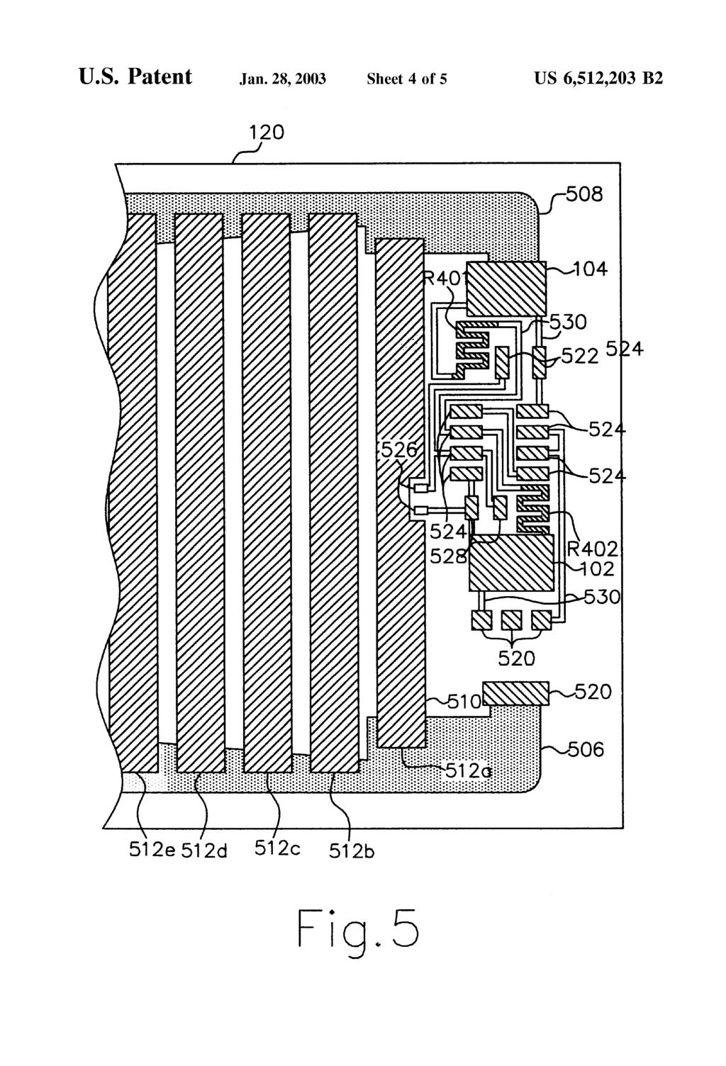
9 S the resistivity, of the ink is controlled by adjusting the amount of conductive material in the ink. In this embodiment, the resistive ink is a low-ohm carbon ink. This type of ink maintains a relatively constant resistance with respect to temperature and is less expensive than positive temperature coefficient (PTC) carbon ink. Polymer thick film ink has other properties, including Viscosity, which determine the method of application. Selecting the Viscosity and other properties for a particular method of application is known in the art. Those skilled in the art will recognize that any of various conductive inkscan be used without departing from the Spirit and Scope of the present invention. In one embodiment, the terminal portions, or area, 102, 104 are formed of Solder paste applied to an exposed portion of the conductive strips 106, 108. Electrical connectors 602 or wire ends are placed in conjunction with the terminal portions 102, 104 and the solder is re-flowed, thereby forming an electrical connection between the terminal por tions 102, 104 and the external circuit. In another embodiment, the terminal portions 102,104 are formed with a conductive Surface to which electrical connections are made by mechanical contact of an external circuit to the exposed conductive Surfaces of the terminal portions 102, 104. The mechanical contact is achieved by a Spring clip or probe connected to the external circuit, which, when in mechanical contact with the exposed conductive Surface, forms an electrical connection. Another embodiment of the present invention provides that the terminal portions 102, 104 are attached to at least a portion of the conductive strip by the use of a conductive adhesive. FIG. 2 illustrates a simplified block diagram of a heater controller circuit with feedback. A power Supply 202 feeds power 212 to a controller 204, which controls the power 218 to a heater 208. A temperature sensor 206 monitors the temperature of the heater 208 and provides a feedback signal 216 to the controller 204. The controller 204 adjusts the power 218 fed to the heater 208 based on the sensed temperature. FIG. 3 illustrates a heater controller circuit for controlling a heater such as illustrated in FIG.1. Abattery 302 serves as the power supply 202. The resister R301 and the thermistor R302 form a voltage divider that feeds a control signal to the base of a metal oxide Semiconductor field effect transistor (MOSFET) Q301. The MOSFET Q301 is wired in common Source configuration with the drain connected to the heater R303. The MOSFET Q301 operates as a voltage controlled potentiometer. The control Voltage, Set by the Voltage divider R301, R302, varies with temperature, which is sensed by the thermistor R302. The output resistance of the MOSFET Q301, which varies typically from 0.1 S2 to greater than 200KS2, is directly related to the gate Voltage. The heater resistance R303 and the voltage supply 202 determines the current rating and power rating of the MOS FET Q301. With this type of circuit, maximum MOSFET Q301 power occurs when the MOSFET Q301 drain voltage is half the supply voltage. Lowest MOSFET power occurs when the MOSFET is fully on or fully off. FIG. 4 illustrates another embodiment of a heater con troller circuit for controlling a heater Such as illustrated in FIG. 1. Unlike the circuit illustrated in FIG. 3, which continually adjusts the power to the heater to regulate its temperature, the circuit of FIG. 4 Switches the heater on and off based on the Sensed temperature. An operational ampli fier Q401 acts as a Voltage comparator that Switches the MOSFET Q402 on and off. The voltage divider formed by US 6,512,203 B the resistor R401 and the resistor R402 provide a reference voltage V1, which is compared to the voltage V2 of the voltage divider formed by the resistor R403 and the ther mistor R404. As the sensed temperature rises and the resis tance of the thermistor R404 increases, the voltage V2 increases. The output of the voltage comparator Q401 changes from low to high depending upon whether the voltage V2 exceeds the reference voltage V1. The bistable output of the voltage comparator Q401 is connected to the gate of the MOSFET Q402 and causes the MOSFET Q402 to pass either minimum or maximum current, depending on whether the output of the voltage comparator Q401 is low or high. A bypass capacitor C401 ensures the output is clean and noise-free at the threshold point, thus preventing the MOSFET Q402 from operating in the high power Zone. The circuit of FIG. 4, although requiring additional components, does not require an expensive high-power MOSFET as does the circuit of FIG. 3. In one embodiment, the resistors R401, R402 are formed by applying resistive ink to the substrate 120, and the other components are Surface mounted on the substrate 120. Those skilled in the art will recognize that the heater circuits depicted in FIGS. 3 and 4 are illustrative and can be varied, depending upon the actual components used, without departing from the Spirit and Scope of the present invention. FIG. 5 illustrates one embodiment of a heater circuit on a substrate. The conductive strips 506, 508 span opposite edges of one surface of the glass substrate 120. The resistive strips 510,512 extend from the first conductive strip 506 to the second conductive strip 508. The resistive strips 510,512 overlap the conductive strips 506, 508. In the illustrated embodiment, the conductive strips 506, 508 have a shape that becomes wider in the transverse direction as the con ductive strips 506, 508 extend away from the circuit con nections 520, 104. This expansion in the width serves to distribute the power evenly to the resistive strips 512. The resistive strip 510 has an indentation at its midpoint, near the mounting pads 526 for the thermistor R404. This arrangement permits the thermistor R404, after it is soldered to the mounting pads 526, to monitor the temperature of the resistive strip 510. FIG. 5 illustrates the interconnecting conductive strips 530 that provide an electrical path between the various circuit elements. Also shown are the MOSFET O402 mount ing pads 520, the resistor R403 mounting pads 522, the operational amplifier Q401 mounting pads 524, the ther mistor R404 mounting pads 526, the capacitor C401 mount ing pads 528, and the terminal portion or areas 102,104. The exposed surfaces of the mounting pads 520, 522, 524,526, 528 and the terminal areas 102, 104 are conductive ink with copper filler and are suitable for re-flow soldering. FIG. 5 shows two resistors R401, R402 Screen printed on the substrate 120 and connected to the power supply 302 terminal areas 102, 104 and to one connection pad 524 for the operational amplifier Q401. FIG. 6 illustrates an embodiment of a heater circuit on a Substrate with the control circuit encapsulated in a potting compound 614 and the heater element and substrate 120 covered with a backing material 612. A pair of power Supply connection terminals 602a, 602b are shown extending from the substrate 120. The resistor R403, the thermistor R404 the operational amplifier Q401, the MOSFET Q402, the capaci tor C401 are surface mounted to the substrate 120 by re-flow Soldering their connection pads to the mounting pads 520, 522, 524,526, 528. A backing material or protective mem brane 612, sized to cover the Substrate 120 and with a cutout sized to fit the controller circuit and the terminals 602a,

10 7 602b, is adhered to the Substrate 120 and polymer thick film ink layers. The backing material 612 cutout is filled with a potting compound 614 to protect and Seal the controller circuit components. In one embodiment, the backing mate rial 612 is used in lieu of the dielectric layer. In another embodiment, the backing material 612 is used in conjunc tion with the dielectric layer. The backing material 612, in one embodiment, is either paper, a vinyl sheet, a flexible elastomeric sheet, or Some other material glued to the Substrate and covering the polymer thick film ink layers. The backing material 612 serves to hold the pieces of the Substrate 120 if the Substrate 120 were to shatter or break. The backing material 612 also protects the circuit applied to the Substrate 120. In one embodiment, the method of attaching a heating element to a Substrate includes the Steps of preparing the substrate, applying conductive ink 106, 108 to a specified area of one Surface of the Substrate 120, applying a resistive ink 110 to the surface of the substrate 120, applying a dielectric over the cured ink, and applying electrical con nection pads 102,104 to each conductive strip 106, 108. The final Step is electrical testing to Verify ink resistance and operability. The polymer thick film inks are applied by Screen printing the ink and then by curing the ink with heat. These Steps are followed for each Successive layer of ink and for applying the dielectric. The conductive strips 106, 108 are the power bus for the heater and must have a low sheet resistance, otherwise heat will not be evenly distributed throughout the heater 110. In one embodiment, the conductive Strip material is a Silver ink with a sheet resistance of approximately 20 m2/sq. In one embodiment, a thermosetting carbon ink of approximately 20 G.2/Sq. is used for the resistive strip heating element 110. The final dielectric is a relatively thick vinyl coating that insulates and protects the heating element. The flexible vinyl coating also prevents the glass from breaking into loose pieces in the event that the glass becomes shattered. Another embodiment uses a backing sheet, either by itself without the dielectric coating or over the dielectric coating, adhered to the substrate and polymer thick film inks. Those skilled in the art will recognize that various materials can be used for the dielectric and the backing sheet without departing from the Spirit and Scope of the present invention. The electrical test is a resistance measurement to deter mine whether the applied circuit elements are within toler ance. Generally, a preferred tolerance oft20% is acceptable; however, if it is necessary to have a tighter tolerance, it 10% is possible. If a Soldered connection to the heater is required, a footprint of copper can be printed on top of the Silver. Solderable polymer thick film (PTF) copper has a sheet resistance of approximately 100 m2/sq. and is suitable for use in place of the Silver for low power heaters. If the copper resistance were too high for the power bus, another Step of applying copper would be required after the Step of applying the Silver conductive Strip. In another embodiment, the method of attaching a heating element to a Substrate includes attaching a heater and the control circuitry to the substrate. The method includes the Steps of applying conductive ink to a specified area of one Surface of the Substrate, applying resistive ink to the Surface of the Substrate, applying copper to the Substrate, applying a dielectric, applying Solder paste, assembling components, and re-flow Soldering the components. The final Step is electrical testing. In the embodiment illustrated in FIG. 4, the resistive ink forms the heating element R303 and the US 6,512,203 B control circuit resistors R401, R402. The other components Q401, Q402, C401, R403, R404 are surface mounted com ponents. Another embodiment includes the Step of adhering a backing material 612 to the substrate 120 and ink layers. The methods described above are not limited to attaching a single heating element to a Substrate. For flat Substrates, an array of heating elements are applied to a Substrate, which is then cut into individual Sections. Curved Substrates are printed on Single line multiple nest plates and assembled as Single Substrates. From the foregoing description, it will be recognized by those skilled in the art that apparatus and methods of attaching a heating element to a glass Substrate has been provided. The heating element is formed from various conductive polymer thick film inks applied to a Substrate. The heating element includes a resistive Strip or film, conductive Strips or conductors, and terminal portions or areas, which form part of an electrical circuit. Electrical power applied to the terminal portions causes current to flow through the resistive film, which generates heat through resistive heating. The heat is transferred to the SubStrate. While the present invention has been illustrated by description of several embodiments and while the illustra tive embodiments have been described in considerable detail, it is not the intention of the applicant to restrict or in any way limit the Scope of the appended claims to Such detail. Additional advantages and modifications will readily appear to those skilled in the art. The invention in its broader aspects is therefore not limited to the Specific details, rep resentative apparatus and methods, and illustrative examples shown and described. Accordingly, departures may be made from Such details without departing from the Spirit or Scope of applicant s general inventive concept. Having thus described the aforementioned invention, We claim: 1. An apparatus for electrically heating a Substrate, Said apparatus comprising: a Substrate having a Surface, Said Substrate being a glass material; a first conductor adhered to Said Surface; a Second conductor adhered to Said Surface; a resistive film adhered to Said Surface, Said resistive film in electrical contact with Said first conductor, Said resistive film in electrical contact with Said Second conductor; a temperature Sensor attached to Said Substrate; and a controller in electrical communication with Said tem perature Sensor, Said first conductor, and Said Second conductor, Said controller having a circuit formed on Said Substrate. 2. The apparatus of claim 1 wherein Said resistive film is formed from a polymer thick film ink having a Specified conductivity, Said resistive film being applied to Said Sur face. 3. The apparatus of claim 1 wherein said first conductor is formed from a first conductive polymer thick film ink and Said Second conductor is formed from a Second conductive polymer thick film ink. 4. The apparatus of claim 1 further comprising a dielectric in contact with Said resistive film, Said first conductor, and Said Second conductor. 5. The apparatus of claim 1 further comprising a backing sheet in contact with Said resistive film, Said first conductor, and Said Second conductor, whereby Said backing sheet protects said resistive film, Said first conductor, and Said Second conductor from an external environment.

11 9 6. The apparatus of claim 1 wherein Said Substrate is a mirror, and Said Surface has a reflective coating. 7. The apparatus of claim 1 wherein said controller is encapsulated in a potting compound. 8. The apparatus of claim 1 wherein Said temperature Sensor is a thermistor, Said temperature Sensor in contact with a pair of thickfilm conductors adhered to Said Surface, and Said controller includes a Semiconductor Switch. 9. The apparatus of claim 1 wherein said resistive film includes a plurality of Strips, each of Said plurality of Strips extending from Said first conductor to Said Second conductor, each of Said plurality of Strips in a Spaced apart configuration. 10. The apparatus of claim 1 wherein said first conductor and Said Second conductor each having a first width at a first end and a Second width at a Second end, Said Second width being wider than Said first width, each said first end having an electrical connection for energizing Said resistive film. 11. An apparatus for heating a Substrate, Said apparatus comprising: a Substrate having a Surface, Said Substrate being a glass material; a first conductor adhered to Said Surface, Said first con ductor being formed from a first conductive polymer thick film ink; a Second conductor adhered to Said Surface, Said Second conductor being formed from a Second conductive polymer thick film ink; a resistive film in contact with Said Surface, Said resistive film being formed from a first polymer thick film carbon ink having a specified conductivity, Said resis tive film in electrical contact with Said first conductor, Said resistive film in electrical contact with Said Second conductor, Said resistive film including a plurality of Strips, each of Said plurality of Strips extending from Said first conductor to Said Second conductor, each of Said plurality of Strips in a Spaced apart configuration; and a temperature Sensor attached to Said Substrate, Said temperature Sensor being a thermistor. 12. The apparatus of claim 11 further comprising a coating in contact with Said resistive film, Said coating in contact with Said first conductor and Said Second conductor. 13. The apparatus of claim 11 further including a con troller in electrical communication with Said temperature Sensor, Said first conductor, and Said Second conductor, Said controller having a circuit formed on Said Substrate. 14. The apparatus of claim 13 wherein said controller includes at least one resistor in contact with Said Surface, Said at least one resistor formed from a Second polymer thick film carbon ink having a specified conductivity; US 6,512,203 B2 1O at least one interconnecting conductor in contact with Said Surface, Said at least one interconnecting conductor formed from said conductive polymer thick film ink; and at least one Semiconductor mounted on Said Substrate. 15. An apparatus for heating a Substrate, Said apparatus comprising: a Substrate having a Surface, Said Substrate being a glass material; a means for heating Said Substrate; a means for Sensing a temperature of Said Substrate; a means for controlling Said means for heating, and a means for connecting Said means for controlling to an electrical power Supply. 16. The apparatus of claim 15 wherein said means for controlling being mounted on Said Substrate. 17. A method of heating a Substrate with a resistance heater printed on the Substrate, Said method comprising the Steps of (a) applying a conductive polymer thick film ink to a first Selected portion of a Surface of a glass Substrate wherein Said first Selected portion includes two areas that are electrically insulated from each other; (b) applying a resistive polymer thick film ink to a second Selected portion of Said Surface, wherein Said resistive polymer thick film ink is in contact with each of Said two areas, (c) applying a first voltage to a controller mounted on said glass Substrate; (d) measuring a temperature of Said glass Substrate with a Surface mounted Sensor; and (e) controlling said first voltage to produce a second Voltage applied to Said resistive polymer thick film ink and to maintain a Selected temperature. 18. The method of claim 17 further comprising a step of applying a dielectric over Selected portions of Said conduc tive ink and Said resistive ink. 19. The method of claim 17 further comprising a step of applying a backing sheet over Said glass Substrate, Said conductive polymer thick film ink, and Said resistive poly mer thick film ink. 20. The method of claim 17 further comprising a step of applying a plurality of electrical connection pads to Selected portions of Said Surface, Said plurality of electrical connec tion pads being formed of Solder paste, and a step of mounting at least one component to Said Substrate, and a step of re-flow Soldering Said at least one component to Said plurality of electrical connection pads. k k k k k
(12) Patent Application Publication (10) Pub. No.: US 2010/ A1
 Patent Application Publication (10) Pub. No.: US 2010/ A1") (19) United States US 2010O136392A1 (12) Patent Application Publication (10) Pub. No.: US 2010/0136392 A1 PULLIAM et al. (43) Pub. Date: Jun. 3, 2010 (54) CELL TEMPERATURE SENSING (21) Appl. No.: 12/571,926
(19) United States US 2010O136392A1 (12) Patent Application Publication (10) Pub. No.: US 2010/0136392 A1 PULLIAM et al. (43) Pub. Date: Jun. 3, 2010 (54) CELL TEMPERATURE SENSING (21) Appl. No.: 12/571,926
54 CONDUCTIVELY.JACKETED COAXIAL 4,532,375 7/1985 Weitzel et al /102 SC X
 United States Patent (19) VanDeusen (45) 11) Patent Number: Date of Patent: 5,037,999 Aug. 6, 1991 54 CONDUCTIVELY.JACKETED COAXIAL 4,454,379 6/1984 Cleveland et al.... 174/106 SCX CABLE 4,472,597 9/1984
(12) United States Patent (10) Patent No.: US 7,190,120 B1
 United States Patent (10) Patent No.: US 7,190,120 B1") US007190120B1 (12) United States Patent () Patent No.: SansOne et al. (45) Date of Patent: Mar. 13, 2007 (54) AIRPORT STROBE LIGHT MONITORING 4,449,073 A * 5/1984 Mongoven et al.... 315/130 SYSTEM (75)
US007190120B1 (12) United States Patent () Patent No.: SansOne et al. (45) Date of Patent: Mar. 13, 2007 (54) AIRPORT STROBE LIGHT MONITORING 4,449,073 A * 5/1984 Mongoven et al.... 315/130 SYSTEM (75)
United States Patent 19
 United States Patent 19 USOO5853046A 11 Patent Number: 5,853,046 Williams et al. (45) Date of Patent: Dec. 29, 1998 54) HEAT EXCHANGER SEAL APPARATUS 4.914,929 4/1990 Shimazaki. 5,036,931 8/1991 Iritani.
(12) Patent Application Publication (10) Pub. No.: US 2006/ A1
 Patent Application Publication (10) Pub. No.: US 2006/ A1") (19) United States (12) Patent Application Publication (10) Pub. No.: US 2006/0278617 A1 Anantharaman et al. US 20060278617A1 (43) Pub. Date: Dec. 14, 2006 (54) (75) (73) (21) (22) (60) LASER WELDING OF
(19) United States (12) Patent Application Publication (10) Pub. No.: US 2006/0278617 A1 Anantharaman et al. US 20060278617A1 (43) Pub. Date: Dec. 14, 2006 (54) (75) (73) (21) (22) (60) LASER WELDING OF
(12) United States Patent
 United States Patent") (12) United States Patent Kuroki et al. USOO6467288B2 (10) Patent No.: (45) Date of Patent: Oct. 22, 2002 (54) HEAT-PUMP WATER HEATER (75) Inventors: Jyouji Kuroki, Kariya (JP); Hisayoshi Sakakibara, Nishio
(12) United States Patent Kuroki et al. USOO6467288B2 (10) Patent No.: (45) Date of Patent: Oct. 22, 2002 (54) HEAT-PUMP WATER HEATER (75) Inventors: Jyouji Kuroki, Kariya (JP); Hisayoshi Sakakibara, Nishio
52 U.S. Cl /95; 362/20, 362/276; of the light Switch or for receiving the electrical plug
 US00601 0228A United States Patent (19) 11 Patent Number: 6,010,228 Blackman et al. (45) Date of Patent: Jan. 4, 2000 54 WIRELESS EMERGENCY SAFETY LIGHT 4,631,649 12/1986 McCue et al.... 362/183 WITH SENSING
28, Int. Cl."... H01J 5/32 U.S. Cl /50.54; 220/4.02; 439/76.1; 361/658 Field of Search /52.3, 50.54, 701,906. part.
 United States Patent (19) Bauer et al. USOO5814765A 11 Patent Number: (45) Date of Patent: Sep. 29, 1998 54 (75) 56) WATERPROOF HOUSING WITH A PLUG AND-SOCKET CONNECTION FOR PROTECTION ELECTRONIC CIRCUIT
(12) United States Patent
 United States Patent") (12) United States Patent Oikawa et al. USOO6778394B2 (10) Patent No.: (45) Date of Patent: Aug. 17, 2004 (54) ELECTRONIC DEVICE HAVING A HEAT DSSPATION MEMBER (75) Inventors: Hironori Oikawa, Hadano (JP);
(12) United States Patent Oikawa et al. USOO6778394B2 (10) Patent No.: (45) Date of Patent: Aug. 17, 2004 (54) ELECTRONIC DEVICE HAVING A HEAT DSSPATION MEMBER (75) Inventors: Hironori Oikawa, Hadano (JP);
(12) United States Patent (10) Patent No.: US 7,654,310 B2. Li (45) Date of Patent: Feb. 2, 2010
 United States Patent (10) Patent No.: US 7,654,310 B2. Li (45) Date of Patent: Feb. 2, 2010") USOO765431 OB2 (12) United States Patent (10) Patent No.: Li (45) Date of Patent: Feb. 2, 2010 (54) LOOP HEAT PIPE 6,840,304 B1* 1/2005 Kobayashi et al.... 165,111 7,231,961 B2 * 6/2007 Alex et al....
USOO765431 OB2 (12) United States Patent (10) Patent No.: Li (45) Date of Patent: Feb. 2, 2010 (54) LOOP HEAT PIPE 6,840,304 B1* 1/2005 Kobayashi et al.... 165,111 7,231,961 B2 * 6/2007 Alex et al....
666,667,522, ,566,493 (7. ABSTRACT
 US005.793291A United States Patent 19 11) Patent Number: Thornton 45 Date of Patent: Aug. 11, 1998 54 CHILD ALERT SYSTEM FOR 4,812,819 3/1989 Corsberg... 340/500 AUTOMOBLES 4,831,361 5/1989 Kimura......
United States Patent (19) Grise
 Grise") United States Patent (19) Grise (54) (76) 21 22 (51) (52) (58 (56) ELECTRICAL SEMICONDUCTOR RESISTANCE HEATER Inventor: Frederick G. J. Grise, P.O. Box 186, Osterville, Mass. 02655 Appl. No.: 68,958 Filed:
United States Patent (19) Grise (54) (76) 21 22 (51) (52) (58 (56) ELECTRICAL SEMICONDUCTOR RESISTANCE HEATER Inventor: Frederick G. J. Grise, P.O. Box 186, Osterville, Mass. 02655 Appl. No.: 68,958 Filed:
United States Patent (19) Dean
 Dean") United States Patent (19) Dean 54 (76) 21) 22 63 51 52 58) 56) ARVENTTLATION CONTROL SYSTEM Inventor: Arthur C. Dean, 13403 Vimy Ridge Rd., Alexander, Ark. 72002 Appl. No.: 63,429 Filed: Jun. 18, 1987
United States Patent (19) Dean 54 (76) 21) 22 63 51 52 58) 56) ARVENTTLATION CONTROL SYSTEM Inventor: Arthur C. Dean, 13403 Vimy Ridge Rd., Alexander, Ark. 72002 Appl. No.: 63,429 Filed: Jun. 18, 1987
(12) United States Patent (10) Patent No.: US 6,361,301 B1
 United States Patent (10) Patent No.: US 6,361,301 B1") USOO636.1301B1 (12) United States Patent (10) Patent No.: Scaglotti et al. (45) Date of Patent: Mar. 26, 2002 (54) HEATER ASSEMBLY FOR BLOW MOLDING 5,256,341. 10/1993 Denis et al. PLASTIC PREFORMS 5,549,468
USOO636.1301B1 (12) United States Patent (10) Patent No.: Scaglotti et al. (45) Date of Patent: Mar. 26, 2002 (54) HEATER ASSEMBLY FOR BLOW MOLDING 5,256,341. 10/1993 Denis et al. PLASTIC PREFORMS 5,549,468
(12) United States Patent
 United States Patent") US007 145105B2 (12) United States Patent Gaullard (10) Patent No.: (45) Date of Patent: Dec. 5, 2006 (54) ELECTRIC KETTLE (75) Inventor: Hervé Gaullard, Courtefontaine (FR) (73) Assignee: SEB SA, Ecully
US007 145105B2 (12) United States Patent Gaullard (10) Patent No.: (45) Date of Patent: Dec. 5, 2006 (54) ELECTRIC KETTLE (75) Inventor: Hervé Gaullard, Courtefontaine (FR) (73) Assignee: SEB SA, Ecully
(12) United States Patent
 United States Patent") USOO9655489B2 (12) United States Patent Ha et al. (10) Patent No.: (45) Date of Patent: US 9,655.489 B2 May 23, 2017 (54) VACUUM CLEANER (71) Applicant: LG ELECTRONICS INC., Seoul (KR) (72) Inventors:
USOO9655489B2 (12) United States Patent Ha et al. (10) Patent No.: (45) Date of Patent: US 9,655.489 B2 May 23, 2017 (54) VACUUM CLEANER (71) Applicant: LG ELECTRONICS INC., Seoul (KR) (72) Inventors:
(12) United States Patent
 United States Patent") (12) United States Patent US006 173454B1 (10) Patent No.: US 6,173,454 B1 Alvarez (45) Date of Patent: Jan. 16, 2001 (54) JONNISAFE 5,191,991 3/1993 Jackson... 220/207 5,347,663 9/1994 Yost... 4/253 (76)
(12) United States Patent US006 173454B1 (10) Patent No.: US 6,173,454 B1 Alvarez (45) Date of Patent: Jan. 16, 2001 (54) JONNISAFE 5,191,991 3/1993 Jackson... 220/207 5,347,663 9/1994 Yost... 4/253 (76)
(12) United States Patent
 United States Patent") () United States Patent Wells et al. USOO6345685B1 (10) Patent No.: (45) Date of Patent: Feb., 2002 (54) LOUDSPEAKER SYSTEM (76) Inventors: Leigh D. Wells; Emma-Jane Smith, both of Providence Cottage,
() United States Patent Wells et al. USOO6345685B1 (10) Patent No.: (45) Date of Patent: Feb., 2002 (54) LOUDSPEAKER SYSTEM (76) Inventors: Leigh D. Wells; Emma-Jane Smith, both of Providence Cottage,
(12) United States Patent (10) Patent No.: US 6,443,434 B1
 United States Patent (10) Patent No.: US 6,443,434 B1") USOO6443434B1 (12) United States Patent (10) Patent No.: Prather (45) Date of Patent: Sep. 3, 2002 (54) FORCED-AIR SCENT DISPENSER 5,970,643 A 10/1999 Gawel, Jr.... 43/1 6,050,016 A * 4/2000 Cox... (76)
USOO6443434B1 (12) United States Patent (10) Patent No.: Prather (45) Date of Patent: Sep. 3, 2002 (54) FORCED-AIR SCENT DISPENSER 5,970,643 A 10/1999 Gawel, Jr.... 43/1 6,050,016 A * 4/2000 Cox... (76)
(12) United States Patent (10) Patent No.: US 6,552,309 B1
 United States Patent (10) Patent No.: US 6,552,309 B1") USOO6552309B1 (12) United States Patent (10) Patent No.: US 6,552,309 B1 Kish et al. (45) Date of Patent: Apr. 22, 2003 (54) PROGRAMMABLE COOKING OR BAKING 5,938,966 A * 8/1999 Oh et al.... 219/702 APPARATUS
USOO6552309B1 (12) United States Patent (10) Patent No.: US 6,552,309 B1 Kish et al. (45) Date of Patent: Apr. 22, 2003 (54) PROGRAMMABLE COOKING OR BAKING 5,938,966 A * 8/1999 Oh et al.... 219/702 APPARATUS
219,432,433,436,528,529, 99,483 is ABSTRACT 56) References Cited
 References Cited") USOO6075229A United States Patent (19) 11 Patent Number: 6,075,229 Vanselow (45) Date of Patent: Jun. 13, 2000 54). CUP WARMER HOLDER 4,442,343 4/1984 Genuit et al.... 219/433 4,463,664 8/1984 Peace......
USOO6075229A United States Patent (19) 11 Patent Number: 6,075,229 Vanselow (45) Date of Patent: Jun. 13, 2000 54). CUP WARMER HOLDER 4,442,343 4/1984 Genuit et al.... 219/433 4,463,664 8/1984 Peace......
United States Patent (19) Jackson
 Jackson") United States Patent (19) Jackson (54) 76 21 22) (51) 52) 58) 56) BUILDING EXTERIOR FIRE PREVENTION SYSTEM Inventor: Willie C. Jackson, 2.4808 Mission Blvd., Hayward, Calif. 94545 Appl. No.:754,792 Filed:
United States Patent (19) Jackson (54) 76 21 22) (51) 52) 58) 56) BUILDING EXTERIOR FIRE PREVENTION SYSTEM Inventor: Willie C. Jackson, 2.4808 Mission Blvd., Hayward, Calif. 94545 Appl. No.:754,792 Filed:
(12) Patent Application Publication (10) Pub. No.: US 2014/ A1
 Patent Application Publication (10) Pub. No.: US 2014/ A1") (19) United States US 2014O137590A1 (12) Patent Application Publication (10) Pub. No.: US 2014/0137590 A1 Chopko et al. (43) Pub. Date: May 22, 2014 (54) INTEGRATED TRANSPORT Publication Classification
(19) United States US 2014O137590A1 (12) Patent Application Publication (10) Pub. No.: US 2014/0137590 A1 Chopko et al. (43) Pub. Date: May 22, 2014 (54) INTEGRATED TRANSPORT Publication Classification
(12) United States Patent (10) Patent No.: US 7, B2
 United States Patent (10) Patent No.: US 7, B2") US007106205B2 (12) United States Patent (10) Patent No.: US 7,106.205 B2 Graef et al. (45) Date of Patent: Sep. 12, 2006 (54) ALARM DEVICE FOR USE WITH FALL 4,846,313 A 7/1989 Sharp PROTECTION EOUIPMENT
US007106205B2 (12) United States Patent (10) Patent No.: US 7,106.205 B2 Graef et al. (45) Date of Patent: Sep. 12, 2006 (54) ALARM DEVICE FOR USE WITH FALL 4,846,313 A 7/1989 Sharp PROTECTION EOUIPMENT
(12) United States Patent (10) Patent No.: US 7,708,183 B2
 United States Patent (10) Patent No.: US 7,708,183 B2") USOO7708183B2 (12) United States Patent (10) Patent No.: Dautenhahn (45) Date of Patent: May 4, 2010 (54) REFLOW SOLDER OVEN WITH COOLING 5,611,476 A 3, 1997 Soderlund et al. DIFFUSER 5,641,341 A * 6/1997
USOO7708183B2 (12) United States Patent (10) Patent No.: Dautenhahn (45) Date of Patent: May 4, 2010 (54) REFLOW SOLDER OVEN WITH COOLING 5,611,476 A 3, 1997 Soderlund et al. DIFFUSER 5,641,341 A * 6/1997
(12) United States Patent (10) Patent No.: US 6,692,130 B1
 United States Patent (10) Patent No.: US 6,692,130 B1") USOO6692130B1 (12) United States Patent (10) Patent No.: Snow (45) Date of Patent: Feb. 17, 2004 (54) SOLAR POWERED HEATING AND 5,433,660 A 7/1995 Ohba VENTILATION SYSTEM FOR VEHICLE 5,588.909 A 12/1996
USOO6692130B1 (12) United States Patent (10) Patent No.: Snow (45) Date of Patent: Feb. 17, 2004 (54) SOLAR POWERED HEATING AND 5,433,660 A 7/1995 Ohba VENTILATION SYSTEM FOR VEHICLE 5,588.909 A 12/1996
(12) United States Patent
 United States Patent") (12) United States Patent USOO8141722B2 (10) Patent No.: US 8,141,722 B2 Heroux (45) Date of Patent: Mar. 27, 2012 (54) GARMENT HANGING DEVICE 4.948,019 8, 1990 ROdum 4,953,717 A 9, 1990 ROSch 4,972,961
(12) United States Patent USOO8141722B2 (10) Patent No.: US 8,141,722 B2 Heroux (45) Date of Patent: Mar. 27, 2012 (54) GARMENT HANGING DEVICE 4.948,019 8, 1990 ROdum 4,953,717 A 9, 1990 ROSch 4,972,961
United States Patent (19) Andreasson
 Andreasson") United States Patent (19) Andreasson 11 Patent Number: 45) Date of Patent: Dec. 9, 1986 54 ELECTRICHEATING PAD FOR SEATS AND BACK-RESTS 75) Inventor: 73) Assignee: Jan Andreasson, Mullsjö, Sweden AB Mekania-Verken,
United States Patent (19) Andreasson 11 Patent Number: 45) Date of Patent: Dec. 9, 1986 54 ELECTRICHEATING PAD FOR SEATS AND BACK-RESTS 75) Inventor: 73) Assignee: Jan Andreasson, Mullsjö, Sweden AB Mekania-Verken,
United States Patent 19) Carnahan
 Carnahan") United States Patent 19) Carnahan 54 (76. (21) (22) (51) (52) (58) (56) REMOUNTABLE WALL/CELNG MOLDING Inventor: V. B. Carnahan, 522 Devils Hole Rd., R.D. #1, Cresco, Pa. 18326 Appl. No.: 932,623 Filed:
United States Patent 19) Carnahan 54 (76. (21) (22) (51) (52) (58) (56) REMOUNTABLE WALL/CELNG MOLDING Inventor: V. B. Carnahan, 522 Devils Hole Rd., R.D. #1, Cresco, Pa. 18326 Appl. No.: 932,623 Filed:
(12) United States Patent
 United States Patent") USOO9224626B2 (12) United States Patent Lindley et al. (10) Patent No.: US 9.224,626 B2 (45) Date of Patent: Dec. 29, 2015 (54) (75) (73) (*) (21) (22) (65) (51) (52) (58) COMPOSITE SUBSTRATE FOR LAYERED
USOO9224626B2 (12) United States Patent Lindley et al. (10) Patent No.: US 9.224,626 B2 (45) Date of Patent: Dec. 29, 2015 (54) (75) (73) (*) (21) (22) (65) (51) (52) (58) COMPOSITE SUBSTRATE FOR LAYERED
into "ill (12) Patent Application Publication (10) Pub. No.: US 2008/ A1 (19) United States 12d Roberts (43) Pub. Date: Feb.
 Patent Application Publication (10) Pub. No.: US 2008/ A1 (19) United States 12d Roberts (43) Pub. Date: Feb.") (19) United States US 2008.0034781A1 (12) Patent Application Publication (10) Pub. No.: US 2008/0034781 A1 Roberts (43) Pub. Date: Feb. 14, 2008 (54) BEVERAGE PITCHER COLD PLATE STATION (76) Inventor:
(19) United States US 2008.0034781A1 (12) Patent Application Publication (10) Pub. No.: US 2008/0034781 A1 Roberts (43) Pub. Date: Feb. 14, 2008 (54) BEVERAGE PITCHER COLD PLATE STATION (76) Inventor:
(12) Patent Application Publication (10) Pub. No.: US 2004/ A1
 Patent Application Publication (10) Pub. No.: US 2004/ A1") US 2004O232165A1 (19) United States (12) Patent Application Publication (10) Pub. No.: Lee (43) Pub. Date: Nov. 25, 2004 (54) GLUE GUN (52) U.S. Cl.... 222/146.5 (76) Inventor: Kuo-Jium Lee, Taichung (TW)
US 2004O232165A1 (19) United States (12) Patent Application Publication (10) Pub. No.: Lee (43) Pub. Date: Nov. 25, 2004 (54) GLUE GUN (52) U.S. Cl.... 222/146.5 (76) Inventor: Kuo-Jium Lee, Taichung (TW)
(12) Patent Application Publication (10) Pub. No.: US 2007/ A1. ZOumut (43) Pub. Date: Mar. 15, 2007
 Patent Application Publication (10) Pub. No.: US 2007/ A1. ZOumut (43) Pub. Date: Mar. 15, 2007") US 2007.0056599A1 (19) United States (12) Patent Application Publication (10) Pub. No.: US 2007/0056599 A1 ZOumut (43) Pub. Date: Mar. 15, 2007 (54) HOOKAH BOWL (52) U.S. Cl.... 131/329; 131/173 (76) Inventor:
US 2007.0056599A1 (19) United States (12) Patent Application Publication (10) Pub. No.: US 2007/0056599 A1 ZOumut (43) Pub. Date: Mar. 15, 2007 (54) HOOKAH BOWL (52) U.S. Cl.... 131/329; 131/173 (76) Inventor:
(12) United States Patent (10) Patent No.: US 6,176,097 B1. Kim (45) Date of Patent: Jan. 23, 2001
 United States Patent (10) Patent No.: US 6,176,097 B1. Kim (45) Date of Patent: Jan. 23, 2001") USOO6176097B1 (12) United States Patent (10) Patent No.: Kim (45) Date of Patent: Jan. 23, 2001 (54) SIDE BY SIDE TYPE REFRIGERATOR AND 5,477,699 12/1995 Guess et al.... 62/187 METHOD FOR CONTROLLING 5,732,561
USOO6176097B1 (12) United States Patent (10) Patent No.: Kim (45) Date of Patent: Jan. 23, 2001 (54) SIDE BY SIDE TYPE REFRIGERATOR AND 5,477,699 12/1995 Guess et al.... 62/187 METHOD FOR CONTROLLING 5,732,561
E=Eal. United States Patent (19) Grooms NN N N E. 11) Patent Number: 4,821, Date of Patent: Apr. 11, 1989
 Grooms NN N N E. 11) Patent Number: 4,821, Date of Patent: Apr. 11, 1989") United States Patent (19) Grooms 54 EAR-MOUNTED ALARM CLOCK 76) Inventor: Reginald M. Grooms, Rte. 6, Box 43, Conway, S.C. 29526 21 Appl. No.: 649,591 22 Filed: Sep. 11, 1984 511 Int. Cl."... G04B 21/08
United States Patent (19) Grooms 54 EAR-MOUNTED ALARM CLOCK 76) Inventor: Reginald M. Grooms, Rte. 6, Box 43, Conway, S.C. 29526 21 Appl. No.: 649,591 22 Filed: Sep. 11, 1984 511 Int. Cl."... G04B 21/08
(12) United States Patent (10) Patent No.: US 7,014,690 B2
 United States Patent (10) Patent No.: US 7,014,690 B2") USOO7014690B2 (12) United States Patent (10) Patent No.: US 7,014,690 B2 Mitsch et al. (45) Date of Patent: Mar. 21, 2006 (54) EXPANDABLE DESICCANTELEMENT 5,689,893 A 11/1997 Mitsch 5,715,621. A 2/1998
USOO7014690B2 (12) United States Patent (10) Patent No.: US 7,014,690 B2 Mitsch et al. (45) Date of Patent: Mar. 21, 2006 (54) EXPANDABLE DESICCANTELEMENT 5,689,893 A 11/1997 Mitsch 5,715,621. A 2/1998
United States Patent (19)
") United States Patent (19) Fingerett et al. 54) LEASH POUCH FOR ANIMAL WASTE 75 Inventors: Allison Marie Fingerett, Minneapolis, Minn.; Ricki Hope Gale, 5036 Oakland Ave. S., Minneapolis, Minn. 55417; Steven
United States Patent (19) Fingerett et al. 54) LEASH POUCH FOR ANIMAL WASTE 75 Inventors: Allison Marie Fingerett, Minneapolis, Minn.; Ricki Hope Gale, 5036 Oakland Ave. S., Minneapolis, Minn. 55417; Steven
United States Patent (19) Bratt
 Bratt") United States Patent (19) Bratt 54) (75) (73) 21 22 63) (51) (52) (58) (56) HOT GAS ENGINE HEATER HEAD Inventor: Jan C. Bratt, Malmö, Sweden Assignee: United Stirling AB, Malmö, Sweden Appl. No.: 852,071
United States Patent (19) Bratt 54) (75) (73) 21 22 63) (51) (52) (58) (56) HOT GAS ENGINE HEATER HEAD Inventor: Jan C. Bratt, Malmö, Sweden Assignee: United Stirling AB, Malmö, Sweden Appl. No.: 852,071
A1(t1) (12) Patent Application Publication (10) Pub. No.: US 2011/ A1. (19) United States. Jiang et al. (43) Pub. Date: Sep.
 (12) Patent Application Publication (10) Pub. No.: US 2011/ A1. (19) United States. Jiang et al. (43) Pub. Date: Sep.") (19) United States US 2011 O232884A1 (12) Patent Application Publication (10) Pub. No.: US 2011/0232884 A1 Jiang et al. (43) Pub. Date: Sep. 29, 2011 (54) HEAT EXCHANGER (75) Inventors: Jianlong Jiang,
(19) United States US 2011 O232884A1 (12) Patent Application Publication (10) Pub. No.: US 2011/0232884 A1 Jiang et al. (43) Pub. Date: Sep. 29, 2011 (54) HEAT EXCHANGER (75) Inventors: Jianlong Jiang,
(12) Patent Application Publication (10) Pub. No.: US 2003/ A1
 Patent Application Publication (10) Pub. No.: US 2003/ A1") (19) United States US 20030051381A1 (12) Patent Application Publication (10) Pub. No.: US 2003/0051381A1 Hernandez et al. (43) Pub. Date: Mar. 20, 2003 (54) POSTER BOARD WITH HANDLES (76) Inventors: Henry
(19) United States US 20030051381A1 (12) Patent Application Publication (10) Pub. No.: US 2003/0051381A1 Hernandez et al. (43) Pub. Date: Mar. 20, 2003 (54) POSTER BOARD WITH HANDLES (76) Inventors: Henry
United States Patent (19) Olin et al.
 Olin et al.") United States Patent (19) Olin et al. 54) VACUUM TOILET UNIT 75 Inventors: Henry Olin, Espoo; Gunner Lindroos, Helsinki; Roland Mattsson, Espoo, all of Finland 73 Assignee: Evac International Oy, Helsinki,
United States Patent (19) Olin et al. 54) VACUUM TOILET UNIT 75 Inventors: Henry Olin, Espoo; Gunner Lindroos, Helsinki; Roland Mattsson, Espoo, all of Finland 73 Assignee: Evac International Oy, Helsinki,
United States Patent (19)
") United States Patent (19) Carnagie et al. 54 75 73 21 22 51 (52) 58 56 DEVICE FOR HEATING AND COOLNG A BEVERAGE Inventors: Jeffrey C. Carnagie, Owenton, Ky.; Robert Strauch, Dearborn Heights, Mich. Assignee:
United States Patent (19) Carnagie et al. 54 75 73 21 22 51 (52) 58 56 DEVICE FOR HEATING AND COOLNG A BEVERAGE Inventors: Jeffrey C. Carnagie, Owenton, Ky.; Robert Strauch, Dearborn Heights, Mich. Assignee:
IIIHHHHHHHHHHHHH. United States Patent (19) CSi. 11 Patent Number: 5,318,230 (45) Date of Patent: Jun. 7, Ferguson et al.
 CSi. 11 Patent Number: 5,318,230 (45) Date of Patent: Jun. 7, Ferguson et al.") United States Patent (19) Ferguson et al. 54 GARBAGE DISPOSAL ASSEMBLY WITH DECORATIVE SINK FLANGE MASK 75 Inventors: Lloyd G. Ferguson, Marietta, Ga.; Peter J. Taylor, Bishops Wood, United Kingdom 73)
United States Patent (19) Ferguson et al. 54 GARBAGE DISPOSAL ASSEMBLY WITH DECORATIVE SINK FLANGE MASK 75 Inventors: Lloyd G. Ferguson, Marietta, Ga.; Peter J. Taylor, Bishops Wood, United Kingdom 73)
(12) United States Patent (10) Patent No.: US 6,647,932 B1
 United States Patent (10) Patent No.: US 6,647,932 B1") USOO664.7932B1 (12) United States Patent (10) Patent No.: Cui et al. (45) Date of Patent: Nov. 18, 2003 (54) COMPACT BOILER WITH TANKLESS (56) References Cited HEATER FOR PROVIDING HEAT AND DOMESTIC HOT
USOO664.7932B1 (12) United States Patent (10) Patent No.: Cui et al. (45) Date of Patent: Nov. 18, 2003 (54) COMPACT BOILER WITH TANKLESS (56) References Cited HEATER FOR PROVIDING HEAT AND DOMESTIC HOT
(12) United States Patent (10) Patent No.: US 7,246,968 B1
 United States Patent (10) Patent No.: US 7,246,968 B1") USOO724.6968B1 (12) United States Patent (10) Patent No.: Priest (45) Date of Patent: Jul. 24, 2007 (54) STORM SEWER INLET GRATE SYSTEM 6,106,707 A 8, 2000 Morris 6,231,758 B1 5/2001 Morris (76) Inventor:
USOO724.6968B1 (12) United States Patent (10) Patent No.: Priest (45) Date of Patent: Jul. 24, 2007 (54) STORM SEWER INLET GRATE SYSTEM 6,106,707 A 8, 2000 Morris 6,231,758 B1 5/2001 Morris (76) Inventor:
(12) United States Patent
 United States Patent") (12) United States Patent Demers USOO6648198B2 (10) Patent No.: (45) Date of Patent: Nov. 18, 2003 (54) VACUUM BELT CONVEYOR (75) Inventor: Sylvain Demers, St. Louis de France (CA) (73) Assignee: Voith
(12) United States Patent Demers USOO6648198B2 (10) Patent No.: (45) Date of Patent: Nov. 18, 2003 (54) VACUUM BELT CONVEYOR (75) Inventor: Sylvain Demers, St. Louis de France (CA) (73) Assignee: Voith
(12) United States Patent
 United States Patent") USOO9440513B2 (12) United States Patent Boudard et al. (10) Patent No.: (45) Date of Patent: US 9.440,513 B2 Sep. 13, 2016 (54) ABSORPTION PLATE FOR AN AIR CONDITIONER (75) Inventors: Emmanuel Boudard,
USOO9440513B2 (12) United States Patent Boudard et al. (10) Patent No.: (45) Date of Patent: US 9.440,513 B2 Sep. 13, 2016 (54) ABSORPTION PLATE FOR AN AIR CONDITIONER (75) Inventors: Emmanuel Boudard,
(12) Patent Application Publication (10) Pub. No.: US 2004/ A1
 Patent Application Publication (10) Pub. No.: US 2004/ A1") (19) United States US 2004O140251A1 (12) Patent Application Publication (10) Pub. No.: US 2004/0140251A1 Hsiao (43) Pub. Date: Jul. 22, 2004 (54) ULTRAVIOLET CLEANING WATER DEVICE (76) Inventor: Chih-Ling
(19) United States US 2004O140251A1 (12) Patent Application Publication (10) Pub. No.: US 2004/0140251A1 Hsiao (43) Pub. Date: Jul. 22, 2004 (54) ULTRAVIOLET CLEANING WATER DEVICE (76) Inventor: Chih-Ling
BY Nov. 3, 1970 R. J. ALVAREZ 3,537,132. As Attornyev. Filed Sept. 3, Sheets-Sheet 1
 Nov. 3, 1970 R. J. ALVAREZ HOUSEHOLD REFRIGERATOR WITH THROUGH-THE-DOOR ICE SERVICE Filed Sept. 3, 1968 2 Sheets-Sheet 1 INVENTOR. ROSER. J. AVAREZ. BY 2224 As Attornyev Nov. 3, 1970 R. J. ALWAREZ HOUSEHOLD
(12) United States Patent (10) Patent No.: US 7, B2
 United States Patent (10) Patent No.: US 7, B2") US007191560B2 O (12) United States Patent (10) Patent No.: US 7,191.560 B2 Harris (45) Date of Patent: Mar. 20, 2007 (54) FLYING INSECT TRAP 5,928,194 A 7/1999 Maget 5,938,640 A 8/1999 Maget (76) Inventor:
US007191560B2 O (12) United States Patent (10) Patent No.: US 7,191.560 B2 Harris (45) Date of Patent: Mar. 20, 2007 (54) FLYING INSECT TRAP 5,928,194 A 7/1999 Maget 5,938,640 A 8/1999 Maget (76) Inventor:
United States Patent (19) Endo et al.
 Endo et al.") United States Patent (19) Endo et al. 11 Patent Number: (45) Date of Patent: 4,656,334 Apr. 7, 1987 (54) BED WARMER WITH ABODY TEMPERATURE SENSOR FOR STOPPINGA HIGHER PRESET TEMPERATURE 75) Inventors:
United States Patent (19) Endo et al. 11 Patent Number: (45) Date of Patent: 4,656,334 Apr. 7, 1987 (54) BED WARMER WITH ABODY TEMPERATURE SENSOR FOR STOPPINGA HIGHER PRESET TEMPERATURE 75) Inventors:
(12) United States Patent (10) Patent No.: US B2
 United States Patent (10) Patent No.: US B2") USOO8432266B2 (12) United States Patent (10) Patent No.: US 8.432.266 B2 Varieur (45) Date of Patent: Apr. 30, 2013 (54) PULL STATION D428,351 S 7, 2000 Hohlfelder 6,380,846 B1 4/2002 Hohlfelder (75) Inventor:
USOO8432266B2 (12) United States Patent (10) Patent No.: US 8.432.266 B2 Varieur (45) Date of Patent: Apr. 30, 2013 (54) PULL STATION D428,351 S 7, 2000 Hohlfelder 6,380,846 B1 4/2002 Hohlfelder (75) Inventor:
United States Patent (19) Anwunah et al.
 Anwunah et al.") United States Patent (19) Anwunah et al. (54) BATH ROOM SOAP RECYCLING DEVICE 76 Inventors: Vincent Anwunah, John Anwunah, both of 12015 Prest, Detroit, Mich. 48227 (21) Appl. No.: 398,357 (22 Filed: Mar.
United States Patent (19) Anwunah et al. (54) BATH ROOM SOAP RECYCLING DEVICE 76 Inventors: Vincent Anwunah, John Anwunah, both of 12015 Prest, Detroit, Mich. 48227 (21) Appl. No.: 398,357 (22 Filed: Mar.
United States Patent (19) Helfrich, Jr. et al.
 Helfrich, Jr. et al.") United States Patent (19) Helfrich, Jr. et al. 4 AMBIENT LIGHT SENSORTOUCHSWITCH 7 73 (21) 22 1 2) 8 6) SYSTEM AND METHOD Inventors: Assignee: Appl. No.: Filed: Robert C. Helfrich, Jr.; Jack E. Francis,
United States Patent (19) Helfrich, Jr. et al. 4 AMBIENT LIGHT SENSORTOUCHSWITCH 7 73 (21) 22 1 2) 8 6) SYSTEM AND METHOD Inventors: Assignee: Appl. No.: Filed: Robert C. Helfrich, Jr.; Jack E. Francis,
(12) Patent Application Publication (10) Pub. No.: US 2004/ A1
 Patent Application Publication (10) Pub. No.: US 2004/ A1") (19) United States US 20040206110A1 (12) Patent Application Publication (10) Pub. No.: US 2004/0206110 A1 Lifson et al. (43) Pub. Date: (54) VAPOR COMPRESSION SYSTEM WITH BYPASS/ECONOMIZER CIRCUITS (76)
(19) United States US 20040206110A1 (12) Patent Application Publication (10) Pub. No.: US 2004/0206110 A1 Lifson et al. (43) Pub. Date: (54) VAPOR COMPRESSION SYSTEM WITH BYPASS/ECONOMIZER CIRCUITS (76)
(12) Patent Application Publication (10) Pub. No.: US 2005/ A1
 Patent Application Publication (10) Pub. No.: US 2005/ A1") (19) United States US 20050075593A1 (12) Patent Application Publication (10) Pub. No.: US 2005/0075593 A1 Smith et al. (43) Pub. Date: (54) SELF-CONTAINED HEATING AND COOLING ORTHOPAEDIC BRACE (76) Inventors:
(19) United States US 20050075593A1 (12) Patent Application Publication (10) Pub. No.: US 2005/0075593 A1 Smith et al. (43) Pub. Date: (54) SELF-CONTAINED HEATING AND COOLING ORTHOPAEDIC BRACE (76) Inventors:
(12) United States Patent (10) Patent No.: US 8, B2
 United States Patent (10) Patent No.: US 8, B2") USOO8066475B2 (12) United States Patent (10) Patent No.: US 8,066.475 B2 Bulgrin et al. (45) Date of Patent: Nov. 29, 2011 (54) LABYRINTH COMPRESSION SEAL AND (56) References Cited TURBINE NCORPORATING
USOO8066475B2 (12) United States Patent (10) Patent No.: US 8,066.475 B2 Bulgrin et al. (45) Date of Patent: Nov. 29, 2011 (54) LABYRINTH COMPRESSION SEAL AND (56) References Cited TURBINE NCORPORATING
(21) Appl. No.: 418, Filed: Apr. 7, 1995 (51 Int. CI.'... F28D Ascolillo
 Appl. No.: 418, Filed: Apr. 7, 1995 (51 Int. CI.'... F28D Ascolillo") United States Patent (19) Middleton et al. US005605052A 11 Patent umber: 5,605,052 (45) Date of Patent: Feb. 25, 1997 (54) MIST SPRAY SYSTEM FOR REFRIGERATIO CODESERS (76) Inventors: Stephen C. Middleton;
United States Patent (19) Middleton et al. US005605052A 11 Patent umber: 5,605,052 (45) Date of Patent: Feb. 25, 1997 (54) MIST SPRAY SYSTEM FOR REFRIGERATIO CODESERS (76) Inventors: Stephen C. Middleton;
(12) Patent Application Publication (10) Pub. No.: US 2005/ A1
 Patent Application Publication (10) Pub. No.: US 2005/ A1") (19) United States US 2005.0072175A1 (12) Patent Application Publication (10) Pub. No.: US 2005/0072175A1 Umeo et al. (43) Pub. Date: Apr. 7, 2005 (54) AIR CONDITIONER ANDTRUCK EQUIPPED WITH SAME (76)
(19) United States US 2005.0072175A1 (12) Patent Application Publication (10) Pub. No.: US 2005/0072175A1 Umeo et al. (43) Pub. Date: Apr. 7, 2005 (54) AIR CONDITIONER ANDTRUCK EQUIPPED WITH SAME (76)
(12) (10) Patent No.: US 7, B2 Army, Jr. et al. (45) Date of Patent: Mar. 13, 2007
 (10) Patent No.: US 7, B2 Army, Jr. et al. (45) Date of Patent: Mar. 13, 2007") United States Patent USOO7188488B2 (12) (10) Patent No.: Army, Jr. et al. (45) Date of Patent: Mar. 13, 2007 (54) PACK AND A HALF CONDENSING CYCLE 2003/0084681 A1* 5/2003 Haas... 62/402 PACK WITH COMBINED
United States Patent USOO7188488B2 (12) (10) Patent No.: Army, Jr. et al. (45) Date of Patent: Mar. 13, 2007 (54) PACK AND A HALF CONDENSING CYCLE 2003/0084681 A1* 5/2003 Haas... 62/402 PACK WITH COMBINED
(12) Patent Application Publication (10) Pub. No.: US 2008/ A1
 Patent Application Publication (10) Pub. No.: US 2008/ A1") US 2008.0005926A1 (19) United States (12) Patent Application Publication (10) Pub. No.: US 2008/0005926 A1 Goggin (43) Pub. Date: Jan. 10, 2008 (54) APPARATUS AND METHOD FOR REDUCING CLOTHES DRYER LINT
US 2008.0005926A1 (19) United States (12) Patent Application Publication (10) Pub. No.: US 2008/0005926 A1 Goggin (43) Pub. Date: Jan. 10, 2008 (54) APPARATUS AND METHOD FOR REDUCING CLOTHES DRYER LINT
(12) United States Patent
 United States Patent") US008011 196B2 (12) United States Patent Eber et al. (54) REFRIGERANT CONTROL OF A HEATRECOVERY CHILLER (75) Inventors: Alan Hv Eber, La Crosse, WI (US); Steven J. Pitts, LaCrescent, MN (US); Brian T.
US008011 196B2 (12) United States Patent Eber et al. (54) REFRIGERANT CONTROL OF A HEATRECOVERY CHILLER (75) Inventors: Alan Hv Eber, La Crosse, WI (US); Steven J. Pitts, LaCrescent, MN (US); Brian T.
US 7,588,275 B2. Borg. Sep. 15, (45) Date of Patent: (10) Patent No.: (56) (12) United States Patent (54) (75) (73)
 Date of Patent: (10) Patent No.: (56) (12) United States Patent (54) (75) (73)") US007588275 B2 (12) United States Patent Borg (10) Patent No.: (45) Date of Patent: US 7,588,275 B2 Sep. 15, 2009 (54) (75) (73) (*) (21) (22) (65) (51) (52) (58) (56) COMBINATION MULTIPLE-CANISTER CARRIER
US007588275 B2 (12) United States Patent Borg (10) Patent No.: (45) Date of Patent: US 7,588,275 B2 Sep. 15, 2009 (54) (75) (73) (*) (21) (22) (65) (51) (52) (58) (56) COMBINATION MULTIPLE-CANISTER CARRIER
D.C. (21) Appl. No.: 727,081. (22 Filed: Sep. 27, Int. C... G21C 13/10 52 U.S. C /87; 176/38; 52/ /DIG
 Appl. No.: 727,081. (22 Filed: Sep. 27, Int. C... G21C 13/10 52 U.S. C /87; 176/38; 52/ /DIG") United States Patent (19) Wampole (54) 75 73 NUCLEAR REACTOR INSULATION AND PREHEAT SYSTEM Inventor: Assignee: Nevin C. Wampole, Latrobe, Pa. The United States of America as represented by the United States
United States Patent (19) Wampole (54) 75 73 NUCLEAR REACTOR INSULATION AND PREHEAT SYSTEM Inventor: Assignee: Nevin C. Wampole, Latrobe, Pa. The United States of America as represented by the United States
(12) United States Patent (10) Patent No.: US 6,327,816 B1
 United States Patent (10) Patent No.: US 6,327,816 B1") USOO6327816B1 (12) United States Patent (10) Patent No.: Walterscheid (45) Date of Patent: Dec. 11, 2001 (54) SIPHON APPARATUS FOR WATERING A 5,779,215 7/1998 DeMasi... 248/523 CHRISTMASTREE 6,145,250
USOO6327816B1 (12) United States Patent (10) Patent No.: Walterscheid (45) Date of Patent: Dec. 11, 2001 (54) SIPHON APPARATUS FOR WATERING A 5,779,215 7/1998 DeMasi... 248/523 CHRISTMASTREE 6,145,250
United States Patent Modine et al.
 United States Patent Modine et al. 54 MODULAR AR COOLED CONDENSER 72) Inventors: Arthur B. Modine; Homer D. Hug gins; Neal A. Cook, all of Racine, Wis. 73) Assignee: Modine Manufacturing Company 22 Filed:
(12) Patent Application Publication (10) Pub. No.: US 2004/ A1
 Patent Application Publication (10) Pub. No.: US 2004/ A1") (19) United States US 20040000399A1 (12) Patent Application Publication (10) Pub. No.: US 2004/0000399 A1 Gavula (43) Pub. Date: Jan. 1, 2004 (54) AIR-TO-AIR HEAT PUMP DEFROST BYPASS LOOP (76) Inventor:
(19) United States US 20040000399A1 (12) Patent Application Publication (10) Pub. No.: US 2004/0000399 A1 Gavula (43) Pub. Date: Jan. 1, 2004 (54) AIR-TO-AIR HEAT PUMP DEFROST BYPASS LOOP (76) Inventor:
(12) Patent Application Publication (10) Pub. No.: US 2009/ A1
 Patent Application Publication (10) Pub. No.: US 2009/ A1") (19) United States US 2009001 0625A1 (12) Patent Application Publication (10) Pub. No.: US 2009/0010625 A1 FOWler et al. (43) Pub. Date: Jan. 8, 2009 (54) FLOW THROUGH HEATER (75) Inventors: Lucas L. Fowler,
(19) United States US 2009001 0625A1 (12) Patent Application Publication (10) Pub. No.: US 2009/0010625 A1 FOWler et al. (43) Pub. Date: Jan. 8, 2009 (54) FLOW THROUGH HEATER (75) Inventors: Lucas L. Fowler,
San Francisco, Calif (21) Appl. No.: 810, Filed: Jun. 27, Int. Cl... B01F3/04 52 U.S. C /119 R; 55/244;
 Appl. No.: 810, Filed: Jun. 27, Int. Cl... B01F3/04 52 U.S. C /119 R; 55/244;") United States Patent (19) Genessi (54) LINT INTERCEPTOR 76 Inventor: Richard J. Genessi, 2434 Rivera St., San Francisco, Calif. 941 16 (21) Appl. No.: 810,387 22 Filed: Jun. 27, 1977 51 Int. Cl... B01F3/04
United States Patent (19) Genessi (54) LINT INTERCEPTOR 76 Inventor: Richard J. Genessi, 2434 Rivera St., San Francisco, Calif. 941 16 (21) Appl. No.: 810,387 22 Filed: Jun. 27, 1977 51 Int. Cl... B01F3/04
(12) Patent Application Publication (10) Pub. No.: US 2017/ A1
 Patent Application Publication (10) Pub. No.: US 2017/ A1") (19) United States (12) Patent Application Publication (10) Pub. No.: US 2017/0023402 A1 FOett US 201700234O2A1 (43) Pub. Date: Jan. 26, 2017 (54) (71) (72) (73) (21) (22) (86) (60) ULTRAVOLET LIGHT FLAME
(19) United States (12) Patent Application Publication (10) Pub. No.: US 2017/0023402 A1 FOett US 201700234O2A1 (43) Pub. Date: Jan. 26, 2017 (54) (71) (72) (73) (21) (22) (86) (60) ULTRAVOLET LIGHT FLAME
US A United States Patent (19) 11 Patent Number: 6,067,007 Gioia (45) Date of Patent: May 23, 2000
 11 Patent Number: 6,067,007 Gioia (45) Date of Patent: May 23, 2000") US006067007A United States Patent (19) 11 Patent Number: Gioia (45) Date of Patent: May 23, 2000 54 METHOD AND APPARATUS FOR 5,682,133 10/1997 Johnson et al.. DETECTION, NOTIFICATION AND 5,703,598 12/1997
US006067007A United States Patent (19) 11 Patent Number: Gioia (45) Date of Patent: May 23, 2000 54 METHOD AND APPARATUS FOR 5,682,133 10/1997 Johnson et al.. DETECTION, NOTIFICATION AND 5,703,598 12/1997
(12) Patent Application Publication (10) Pub. No.: US 2009/ A1. LEE (43) Pub. Date: Oct. 29, 2009
 Patent Application Publication (10) Pub. No.: US 2009/ A1. LEE (43) Pub. Date: Oct. 29, 2009") US 20090266353A1 (19) United States (12) Patent Application Publication (10) Pub. No.: US 2009/0266353 A1 LEE (43) Pub. Date: Oct. 29, 2009 (54) AUTOMATIC CLEANING SYSTEM FOR (30) Foreign Application Priority
US 20090266353A1 (19) United States (12) Patent Application Publication (10) Pub. No.: US 2009/0266353 A1 LEE (43) Pub. Date: Oct. 29, 2009 (54) AUTOMATIC CLEANING SYSTEM FOR (30) Foreign Application Priority
United States Patent (19) DeLeonardis
 DeLeonardis") United States Patent (19) DeLeonardis 54 76 21 22 60 51 52 58 56 AUTOMATC NASALASPRATORS Inventor: Rocco J. DeLeonardis, P.O. Box 3093, McLean, Va. 22103 Appl. No.: 697,593 Filed: Aug. 27, 1996 Related
United States Patent (19) DeLeonardis 54 76 21 22 60 51 52 58 56 AUTOMATC NASALASPRATORS Inventor: Rocco J. DeLeonardis, P.O. Box 3093, McLean, Va. 22103 Appl. No.: 697,593 Filed: Aug. 27, 1996 Related
4-26. United States Patent (19) Woollenweber et al. R XI N Patent Number: 6,102,672 (45) Date of Patent: Aug. 15, (75)
 Woollenweber et al. R XI N Patent Number: 6,102,672 (45) Date of Patent: Aug. 15, (75)") United States Patent (19) Woollenweber et al. 54 (75) MOTOR-DRIVEN CENTRIFUGAL AIR COMPRESSOR WITH INTERNAL COOLING ARFLOW Inventors: William E. Woollenweber, Carlsbad; Edward M. Halimi, Montecito, both
United States Patent (19) Woollenweber et al. 54 (75) MOTOR-DRIVEN CENTRIFUGAL AIR COMPRESSOR WITH INTERNAL COOLING ARFLOW Inventors: William E. Woollenweber, Carlsbad; Edward M. Halimi, Montecito, both
US A United States Patent (19) 11) Patent Number: 5,573,058 Rolin (45) Date of Patent: Nov. 12, Sweden B /1981 Finland.
 11) Patent Number: 5,573,058 Rolin (45) Date of Patent: Nov. 12, Sweden B /1981 Finland.") US005573058A United States Patent (19) 11) Patent Number: Rolin (45) Date of Patent: Nov. 12, 1996 54 AIR-CONDITIONING INSTALLATION FOR 4,084,635 4/1978 Marshall... 165/909 ROOM SPACES 4,142,575 3/1979
US005573058A United States Patent (19) 11) Patent Number: Rolin (45) Date of Patent: Nov. 12, 1996 54 AIR-CONDITIONING INSTALLATION FOR 4,084,635 4/1978 Marshall... 165/909 ROOM SPACES 4,142,575 3/1979
(12) Patent Application Publication (10) Pub. No.: US 2008/ A1
 Patent Application Publication (10) Pub. No.: US 2008/ A1") US 2008.0058736A1 (19) United States (12) Patent Application Publication (10) Pub. No.: US 2008/0058736A1 Resham Wala (43) Pub. Date: Mar. 6, 2008 (54) SHARPS CONTAINER HAVING ABSORBENT Publication Classification
US 2008.0058736A1 (19) United States (12) Patent Application Publication (10) Pub. No.: US 2008/0058736A1 Resham Wala (43) Pub. Date: Mar. 6, 2008 (54) SHARPS CONTAINER HAVING ABSORBENT Publication Classification
I I IIII. United States Patent (19) McPhee. 5,537,996 Jul. 23, ) Patent Number: 45) Date of Patent:
 McPhee. 5,537,996 Jul. 23, ) Patent Number: 45) Date of Patent:") United States Patent (19) McPhee I I IIII US005537996A 11) Patent Number: 45) Date of Patent: Jul. 23, 1996 (54) HEATED RESPIRATORY HUMIDIFIER CONDUT (75) Inventor: Stephen W. McPhee, Auckland, New Zealand
United States Patent (19) McPhee I I IIII US005537996A 11) Patent Number: 45) Date of Patent: Jul. 23, 1996 (54) HEATED RESPIRATORY HUMIDIFIER CONDUT (75) Inventor: Stephen W. McPhee, Auckland, New Zealand
(12) Patent Application Publication (10) Pub. No.: US 2007/ A1
 Patent Application Publication (10) Pub. No.: US 2007/ A1") (19) United States US 20070209656A1 (12) Patent Application Publication (10) Pub. No.: US 2007/0209656A1 Lee (43) Pub. Date: Sep. 13, 2007 (54) VAPOR HEATING TYPE COOKING APPARATUS (76) Inventor: Won-Ki
(19) United States US 20070209656A1 (12) Patent Application Publication (10) Pub. No.: US 2007/0209656A1 Lee (43) Pub. Date: Sep. 13, 2007 (54) VAPOR HEATING TYPE COOKING APPARATUS (76) Inventor: Won-Ki
USOO A United States Patent (19) 11 Patent Number: 5,993,656 Cordani (45) Date of Patent: Nov.30, 1999
 11 Patent Number: 5,993,656 Cordani (45) Date of Patent: Nov.30, 1999") USOO5993656A United States Patent (19) 11 Patent Number: 5,993,656 Cordani (45) Date of Patent: Nov.30, 1999 54). SELECTIVE FLUIDABSORBING DEVICE 4,861,469 8/1989 Rossi et al.... 21.0/502.1 5,130,018 7/1992
USOO5993656A United States Patent (19) 11 Patent Number: 5,993,656 Cordani (45) Date of Patent: Nov.30, 1999 54). SELECTIVE FLUIDABSORBING DEVICE 4,861,469 8/1989 Rossi et al.... 21.0/502.1 5,130,018 7/1992
United States Patent (19) Moore, Jr. et al.
 Moore, Jr. et al.") United States Patent (19) Moore, Jr. et al. 54 76 AUTOMATIC SEALING SPRINKLER HEAD ADAPTER AND FIRE PROTECTION SPRINKLER SYSTEM Inventors: Fred D. Moore, Jr., 155 Hunt Dr., Horsham, Pa. 19044; Robert L.
United States Patent (19) Moore, Jr. et al. 54 76 AUTOMATIC SEALING SPRINKLER HEAD ADAPTER AND FIRE PROTECTION SPRINKLER SYSTEM Inventors: Fred D. Moore, Jr., 155 Hunt Dr., Horsham, Pa. 19044; Robert L.
United States Patent (19)
") United States Patent (19) Regan 54 75 (73) (21) 22 51 52 58 56 STEAM AIR PREHEATER FOR MANTAINING THE FLUE GAS TEMPERATURE ENTERNG DUST COLLECTION EQUIPMENT Inventor: Assignee: John W. Regan, Windsor,
United States Patent (19) Regan 54 75 (73) (21) 22 51 52 58 56 STEAM AIR PREHEATER FOR MANTAINING THE FLUE GAS TEMPERATURE ENTERNG DUST COLLECTION EQUIPMENT Inventor: Assignee: John W. Regan, Windsor,
(12) Patent Application Publication (10) Pub. No.: US 2016/ A1
 Patent Application Publication (10) Pub. No.: US 2016/ A1") (19) United States US 201602O767OA1 (12) Patent Application Publication (10) Pub. No.: US 2016/0207670 A1 CHOU (43) Pub. Date: Jul. 21, 2016 (54) ONE-PIECE FOOD CONTAINER WITH RIM (52) U.S. Cl. CPC...
(19) United States US 201602O767OA1 (12) Patent Application Publication (10) Pub. No.: US 2016/0207670 A1 CHOU (43) Pub. Date: Jul. 21, 2016 (54) ONE-PIECE FOOD CONTAINER WITH RIM (52) U.S. Cl. CPC...
United States Patent (19)
") United States Patent (19) Tominaga 54 (75) (73) 21 22) (51) (52) (58) (56) FLTER FOR USE IN A FSH CULTURING TANK Inventor: Assignee: Kazutoshi Tominaga, Higashiosakashi, Japan Kabushiki Kaisha Tominaga
United States Patent (19) Tominaga 54 (75) (73) 21 22) (51) (52) (58) (56) FLTER FOR USE IN A FSH CULTURING TANK Inventor: Assignee: Kazutoshi Tominaga, Higashiosakashi, Japan Kabushiki Kaisha Tominaga
which is a continuation of application No. 08/126,791, filed on Sep. 24, 1993, now abandoned. (51) Int. Cl."... G08B 5/00 340/286.
 Int. Cl.... G08B 5/00 340/286.") (12) United States Patent Stewart et al. USOO6954137B2 (10) Patent No.: (45) Date of Patent: US 6,954,137 B2 *Oct. 11, 2005 (54) BUILDING ALARM SYSTEM WITH SYNCHRONIZED STROBES (75) Inventors: Albert J.
(12) United States Patent Stewart et al. USOO6954137B2 (10) Patent No.: (45) Date of Patent: US 6,954,137 B2 *Oct. 11, 2005 (54) BUILDING ALARM SYSTEM WITH SYNCHRONIZED STROBES (75) Inventors: Albert J.
(12) United States Patent (10) Patent No.: US 6,979,403 B2
 United States Patent (10) Patent No.: US 6,979,403 B2") USOO697.9403B2 (12) United States Patent (10) Patent No.: US 6,979,403 B2 ROdis (45) Date of Patent: Dec. 27, 2005 (54) GREASE INTERCEPTOR (TRAP) AND 4.915,823 A 4/1990 Hall SERVICING METHOD 5,296,150
USOO697.9403B2 (12) United States Patent (10) Patent No.: US 6,979,403 B2 ROdis (45) Date of Patent: Dec. 27, 2005 (54) GREASE INTERCEPTOR (TRAP) AND 4.915,823 A 4/1990 Hall SERVICING METHOD 5,296,150
III. United States Patent (19) Lin 5,116,182. May 26, 1992
 Lin 5,116,182. May 26, 1992") United States Patent (19) Lin 54 AUTOMATIC CARPARKING SYSTEM 76 Inventor: Bao N. Lin, No. 441, Jen AI Rd., Chu Tung Town, Hsin Chu Hsien, Taiwan (21) Appl. No.: 598,969 22 Filed: Oct. 17, 1990 51 int.
United States Patent (19) Lin 54 AUTOMATIC CARPARKING SYSTEM 76 Inventor: Bao N. Lin, No. 441, Jen AI Rd., Chu Tung Town, Hsin Chu Hsien, Taiwan (21) Appl. No.: 598,969 22 Filed: Oct. 17, 1990 51 int.
(12) United States Patent (10) Patent No.: US 6,848,259 B2
 United States Patent (10) Patent No.: US 6,848,259 B2") USOO684.8259B2 (12) United States Patent (10) Patent No.: US 6,848,259 B2 Keller-Sornig et al. (45) Date of Patent: Feb. 1, 2005 (54) COMPRESSED AIR ENERGY STORAGE 5,442,905 A * 8/1995 Claeys et al....
USOO684.8259B2 (12) United States Patent (10) Patent No.: US 6,848,259 B2 Keller-Sornig et al. (45) Date of Patent: Feb. 1, 2005 (54) COMPRESSED AIR ENERGY STORAGE 5,442,905 A * 8/1995 Claeys et al....
(12) United States Patent (10) Patent No.: US 6,920,917 B2
 United States Patent (10) Patent No.: US 6,920,917 B2") USOO6920917B2 (12) United States Patent (10) Patent No.: Inoue et al. (45) Date of Patent: Jul. 26, 2005 (54) DOUBLE-PIPE HEAT EXCHANGER 5,950,716 A 9/1999 Appelquist et al.... 165/109.1 6,220,344 B1 *
USOO6920917B2 (12) United States Patent (10) Patent No.: Inoue et al. (45) Date of Patent: Jul. 26, 2005 (54) DOUBLE-PIPE HEAT EXCHANGER 5,950,716 A 9/1999 Appelquist et al.... 165/109.1 6,220,344 B1 *
(12) Patent Application Publication (10) Pub. No.: US 2006/ A1
 Patent Application Publication (10) Pub. No.: US 2006/ A1") (19) United States US 20060277782A1 (12) Patent Application Publication (10) Pub. No.: Chen et al. (43) Pub. Date: Dec. 14, 2006 (54) NEGATIVE PRESSURE TYPE DRYING MACHINE THAT UTILIZES THE ENERGY OF THE
(19) United States US 20060277782A1 (12) Patent Application Publication (10) Pub. No.: Chen et al. (43) Pub. Date: Dec. 14, 2006 (54) NEGATIVE PRESSURE TYPE DRYING MACHINE THAT UTILIZES THE ENERGY OF THE
(12) United States Patent (10) Patent No.: US 6,440,157 B1
 United States Patent (10) Patent No.: US 6,440,157 B1") USOO644O157B1 (12) United States Patent (10) Patent No.: US 6,440,157 B1 Shigezawa et al. (45) Date of Patent: Aug. 27, 2002 (54) AIR WARMING SYSTEM FOR PROVIDING A OTHER PUBLICATIONS CONTROLLED TEMPERATURE
USOO644O157B1 (12) United States Patent (10) Patent No.: US 6,440,157 B1 Shigezawa et al. (45) Date of Patent: Aug. 27, 2002 (54) AIR WARMING SYSTEM FOR PROVIDING A OTHER PUBLICATIONS CONTROLLED TEMPERATURE
(12) United States Patent (10) Patent No.: US 7,211,771 B1. Smith et al. (45) Date of Patent: May 1, 2007
 United States Patent (10) Patent No.: US 7,211,771 B1. Smith et al. (45) Date of Patent: May 1, 2007") US00721 1771B1 (12) United States Patent (10) Patent No.: US 7,211,771 B1 Smith et al. (45) Date of Patent: May 1, 2007 (54) DE-ICING SYSTEM FOR TRAFFIC SIGNALS 6,045,240 A 4/2000 Hochstein 6,282,969 B1*
US00721 1771B1 (12) United States Patent (10) Patent No.: US 7,211,771 B1 Smith et al. (45) Date of Patent: May 1, 2007 (54) DE-ICING SYSTEM FOR TRAFFIC SIGNALS 6,045,240 A 4/2000 Hochstein 6,282,969 B1*
(12) Patent Application Publication (10) Pub. No.: US 2003/ A1. Quinonez (43) Pub. Date: Jul. 3, 2003
 Patent Application Publication (10) Pub. No.: US 2003/ A1. Quinonez (43) Pub. Date: Jul. 3, 2003") US 2003.0122662A1 (19) United States (12) Patent Application Publication (10) Pub. No.: US 2003/0122662 A1 Quinonez (43) Pub. Date: Jul. 3, 2003 (54) BABY CAR SEAT ALERT AND RANGE (57) ABSTRACT ALARM An
US 2003.0122662A1 (19) United States (12) Patent Application Publication (10) Pub. No.: US 2003/0122662 A1 Quinonez (43) Pub. Date: Jul. 3, 2003 (54) BABY CAR SEAT ALERT AND RANGE (57) ABSTRACT ALARM An
US 9,599,408 Bl Mar.21,2017
 111111 1111111111111111111111111111111111111111111111111111111111111 US009599408B 1 c12) United States Patent Hartenstine et al. (10) Patent No.: (45) Date of Patent: Mar.21,2017 (54) LOOP HEAT PIPE EVAPORATOR
58 Field of Search... 47/40.5, 48.5, opening for receiving water is disguised as a Christmas tree
 USOO6073390A United States Patent (19) 11 Patent Number: 6,073,390 Baudier (45) Date of Patent: Jun. 13, 2000 54 CHRISTMASTREE WATERING DEVICE 5,799.437 9/1998 Evans et al.... 47/40.5 5,867,929 2/1999
(12) United States Patent (10) Patent No.: US 6,902,316 B1
 United States Patent (10) Patent No.: US 6,902,316 B1") USOO6902316B1 (12) United States Patent (10) Patent No.: US 6,902,316 B1 Pierce et al. (45) Date of Patent: Jun. 7, 2005 (54) NON-INVASIVE CORROSION SENSOR 2003/0012254 A1 1/2003 Park et al.... 374/45
USOO6902316B1 (12) United States Patent (10) Patent No.: US 6,902,316 B1 Pierce et al. (45) Date of Patent: Jun. 7, 2005 (54) NON-INVASIVE CORROSION SENSOR 2003/0012254 A1 1/2003 Park et al.... 374/45
(12) United States Patent
 United States Patent") USOO823 O714B2 (12) United States Patent Intagliata et al. (10) Patent No.: US 8,230,714 B2 (45) Date of Patent: Jul. 31, 2012 (54) (75) (73) (*) (21) (22) (65) (60) (51) (52) (58) DE CARRIER ASSEMBLY
USOO823 O714B2 (12) United States Patent Intagliata et al. (10) Patent No.: US 8,230,714 B2 (45) Date of Patent: Jul. 31, 2012 (54) (75) (73) (*) (21) (22) (65) (60) (51) (52) (58) DE CARRIER ASSEMBLY
(12) United States Patent (10) Patent No.: US 6,588,330 B1
 United States Patent (10) Patent No.: US 6,588,330 B1") USOO658833OB1 (12) United States Patent (10) Patent No.: US 6,588,330 B1 Importico (45) Date of Patent: Jul. 8, 2003 (54) TRASH COMPACTOR SYSTEM 5,425,458 6/1995 Gilcreest et al. 5,551,576 A 9/1996 Importico
USOO658833OB1 (12) United States Patent (10) Patent No.: US 6,588,330 B1 Importico (45) Date of Patent: Jul. 8, 2003 (54) TRASH COMPACTOR SYSTEM 5,425,458 6/1995 Gilcreest et al. 5,551,576 A 9/1996 Importico
United States Patent (19) Rundzaitis et al.
 Rundzaitis et al.") United States Patent (19) Rundzaitis et al. 11 Patent Number: (45) Date of Patent: Jun. 12, 1990 54) HOUSING WITH REPLACEABLE FILTER CARTRIDGE FOR USE WITH SHOWER HEAD 75) Inventors: Alfons Rundzaitis,
United States Patent (19) Rundzaitis et al. 11 Patent Number: (45) Date of Patent: Jun. 12, 1990 54) HOUSING WITH REPLACEABLE FILTER CARTRIDGE FOR USE WITH SHOWER HEAD 75) Inventors: Alfons Rundzaitis,
(12) Patent Application Publication (10) Pub. No.: US 2008/ A1
 Patent Application Publication (10) Pub. No.: US 2008/ A1") (19) United States (12) Patent Application Publication (10) Pub. No.: US 2008/0204207 A1 Speers et al. US 20080204207A1 (43) Pub. Date: Aug. 28, 2008 (54) TWO-WAY AUTOMOTIVE REMOTE (76) (21) (22) (51)
(19) United States (12) Patent Application Publication (10) Pub. No.: US 2008/0204207 A1 Speers et al. US 20080204207A1 (43) Pub. Date: Aug. 28, 2008 (54) TWO-WAY AUTOMOTIVE REMOTE (76) (21) (22) (51)
(12) United States Patent (10) Patent No.: US 6,718,974 B1
 United States Patent (10) Patent No.: US 6,718,974 B1") USOO6718974B1 (12) United States Patent (10) Patent No.: Moberg (45) Date of Patent: Apr. 13, 2004 (54) CPAP HUMIDIFIER HAVING SLIDING 5,231.979 A 8/1993 Rose et al. ACCESS DRAWER 5,343,551 A 8/1994 Glucksman...
USOO6718974B1 (12) United States Patent (10) Patent No.: Moberg (45) Date of Patent: Apr. 13, 2004 (54) CPAP HUMIDIFIER HAVING SLIDING 5,231.979 A 8/1993 Rose et al. ACCESS DRAWER 5,343,551 A 8/1994 Glucksman...