Leica CM Cryostat
|
|
|
- Pierce Stephens
- 5 years ago
- Views:
Transcription

1 Leica CM 1850 Cryostat Instruction Manual Leica CM 1850 V2.0 English 03/2001 Always keep this manual near the instrument! Read carefully prior to operating the instrument!
2
3 INFORMATION Serial No.:... Year of Manufacture:... Country of Origin:.. Federal Republic of Germany Leica Microsystems Nussloch GmbH Heidelberger Str D Nussloch Germany Phone: +49 (62 24) Fax: +49 (62 24) Internet: The information, numerical data, notes and value judgments contained in this manual represent the current state of scientific knowledge and stateof-the-art technology as we understand it following thorough investigation in this field. We are under no obligation to update the present manual periodically and on an ongoing basis according to the latest technical developments, nor to provide our customers with additional copies, updates etc. of this manual. For erroneous statements, drawings, technical illustrations etc. contained in this manual we exclude liability as far as permissible according to the national legal system applicable in each individual case. In particular, no liability whatsoever is accepted for any financial loss or consequential damage caused by or related to compliance with statements or other information in this manual. Statements, drawings, illustrations and other information as regards contents or technical details of the present manual are not to be considered as warranted characteristics of our products. These are determined only by the contract provisions agreed between ourselves and our customers. Leica reserves the right to change technical specifications as well as manufacturing processes without prior notice. Only in this way is it possible to continuously improve the technology and manufacturing techniques used in our products. This document is protected under copyright laws. Any copyrights of this document are retained by Leica Microsystems Nussloch GmbH. Any reproduction of text and illustrations (or of any parts thereof) by means of print, photocopy, microfiche, web cam or other methods including any electronic systems and media requires express prior permission in writing by Leica Microsystems Nussloch GmbH. For the instrument serial number and year of manufacture, please refer to the name plate at the back of the instrument. Leica Microsystems Nussloch GmbH Leica CM 1850 Cryostat 3
4 Table of contents 1. Important Information Symbols used in this manual and their meaning Designated use Qualification of personnel Safety Safety features Locking the handwheel Knife guard General information on instrument design and safe handling Operating conditions Cleaning and disinfection Removal of the microtome Maintenance Technical data Unpacking and installation Site requirements Transport to the desired location Standard delivery Handwheel assembly Setup Connection to mains power Prior to operation Leica CM Overview Mains switch and automatic mains fuse Turning the instrument on Control panel operation Control panel Programming the desired values Setting the time Setting the automatic defrost time (cryochamber) Selecting the cryochamber temperature Activation of the Peltier element (option) Manual defrosting of the quick freeze shelf Instruction Manual V2.0 03/2001
5 Table of contents Manual defrosting of the cryochamber Display lock Control panel 2 - Electric coarse feed Daily use of the instrument Specimen freezing Quick freeze shelf Stationary heat extractor (accessory)* Specimen discs Inserting the specimen discs in the specimen head Specimen orientation Sectioning Trimming the specimen Section thickness setting Temperaturew selection chart (in minus C) Defrosting Automatic defrosting of the cryochamber Manual defrosting of the cryochamber Manual defrosting of the quick freeze shelf Terminating work Terminating daily work Shutdown for a longer period Troubleshooting Error messages in the display Temperature control button Possible causes and remedies Cleaning, disinfection, maintenance Cleaning Spray disinfection with Leica Cryofect Maintenance General maintenance Removal of the microtome Removal of the microtome cover Reinstallation of the microtome Leica CM1850 Cryostat 5
6 Table of contents Replacement of the fuses Replacement of the lamp Ordering information, optional accessories Ordering information Optional accessories Mobile heat extractor Thermal block Appendix Instruction Manual V2.0 03/2001
7 1. Important Information The chapters of the Leica CM 1850 cryostat instruction manual: Chapter 1 Chapter 2 Chapter 3 Chapter 4 Chapter 5 Chapter 6 Chapter 7 Chapter 8 Chapter 9 Chapter 10 Appendix Structure of the manual: Table of contents Important information on this manual Safety Read this chapter before operating the instrument! Technical data Unpacking and installation Standard delivery, information on accessories Unpacking and installation Site requirements Standard delivery Setup Overview Turning the instrument on Control panel operation Control panel 1 Programming the desired values Control panel 2 Daily use of the instrument Troubleshooting Cleaning, disinfection, maintenance Ordering information, optional accessories EC Declaration 1.1 Symbols used in this manual and their meaning (5) (Fig.5) Warnings appear in a grey box and are marked by a warning triangle. Notes i.e. important user information appears in a grey box and is marked by an information symbol. Figures in brackets refer to item numbers in drawings or to the drawings themselves. Instrument type: All information given in this instruction manual applies only to the instrument type indicated on the title page. A name plate, indicating the instrument serial number, is attached to the back of the instrument. Required information for all inquiries: For any inquiries please specify: Instrument type Serial number Leica CM 1850 Cryostat 7
8 1. Important Information General 1.2 Designated use 1.3 Qualification of personnel This instruction manual includes important instructions and information related to the operating safety and maintenance of the instrument. The instruction manual is an important part of the product. It must be read carefully before using the instrument for the first time and must always be kept with the instrument. If additional requirements, which exceed the scope of this manual, are imposed by regulations and/or laws on accident prevention and environmental protection in the country of operation, appropriate instructions for compliance with such requirements must be added to this manual. Read this instruction manual carefully before attempting to use or operate the instrument. Please pay particular attention to chapter 2 (safety features, safety instructions). - Please read this information, even if you are already familiar with the operation and use of other Leica products. The Leica CM1850 is a powerful cryostat for routine as well as research applications in biology, medicine and industry. The instrument has been designed for rapid freezing and sectioning of tissue samples. The instrument has not been designed for unattended storage of tissue material. The instrument may only be operated within the scope of its designated use as described above and as per the instructions given in this manual. Any other use of the instrument is considered improper. The Leica CM1850 may only be operated by trained laboratory personnel. All laboratory personnel designated to operate the instrument must carefully read the present instruction manual prior to starting work with the instrument. 8 Instruction Manual V2.0 03/2001
9 2. Safety 2.1 Safety features The instrument and its accessory equipment incorporate the following safety features: safety handwheel and knife guards on the knife holders. The consistent use of these safety features and strict observation of the warnings and cautions in this manual, will safeguard the operator from accidents and/or personal injury to a great extent Locking the handwheel 2 1 Prior to manipulating the knife and specimen, or changing the specimen or knife, and during breaks, always lock the handwheel! Fig For locking the handwheel rotate the handle until it is in the upper position. Push the locking pin (1) into the recess at the handwheel. The locking position is marked by a black dot (2). If necessary, move the handwheel slightly forth and back until the locking mechanism engages. To unlock, push the locking pin (1) to the left from the recess at the handwheel. Fig Knife guard For every manipulation in the cryochamber, or upon changing a specimen when the knife or disposable blade is clamped, or during breaks, cover the cutting edge with the knife guard. The knife holders CN and CS are equipped with knife guards; on the knife holder CE the glass plate of the anti-roll guide constitutes the knife guard (please refer to the separate instruction manual for your knife holder). Prior to manipulating the knife and specimen, or changing the specimen or knife, and during breaks, always lock the handwheel! Leica CM1850 Cryostat 9
10 2. Safety 2.2 General information on instrument design and safe handling This instrument has been built and tested in accordance with the following safety regulations on electrical measuring, control, regulating and laboratory devices: DIN EN 292, DIN EN , EN , EN 55011, IEC as well as according to the international quality standard, DIN ISO In order to maintain this condition and to ensure safe operation, the operator must observe the instructions and warnings contained in this instruction manual. 2.3 Operating conditions Transport and installation Connection to mains After transporting do not turn the instrument on for a minimum of 4 hours! Do not operate in rooms with explosion hazard! To ensure an adequate cooling capacity, the instrument must be set up with at least 10 cm distance from walls and furniture! Before connecting to the mains power, please check if the local voltage complies with the power rating specified on the name plate of the instrument! During the compressor start-up the nominal voltage must not drop below the values specified in the Technical data! The compressor requires a start-up current between 45 and 50 A. Therefore, the electric circuit at the place of installation must be inspected by an electrical engineer to ensure that it meets the requirements for a smooth operation of the instrument. 10 Instruction Manual V2.0 03/2001
11 2. Safety Defrosting A constant adequate power supply to the instrument must be ensured at all times. Failure to comply with the above will cause severe damage to the instrument. After transporting, wait at least 4 hours before turning the instrument on. This waiting period is necessary to allow the compressor oil, which may have been displaced during transport, to return to its original position. Failure to comply with this can cause severe damage to the instrument. The quick freeze shelf may become hot during defrosting! Therefore, do not touch it! 2.4 Operating the instrument Take care when handling microtome knives and disposable blades. The cutting edge is extremely sharp and can cause severe injury! Never leave knives and knife holders with a knife/blade mounted lying around! Do not place a knife on a table with the cutting edge facing upward! Never try to catch a falling knife! Always clamp the specimen before the knife! Prior to manipulating the knife and specimen, or changing the specimen or knife, and during breaks, always lock the handwheel and cover the cutting edge with the knife guard! Avoid contact with cold parts of the instrument as this can cause frostbite! To make sure that the condensation water stemming from the defrost cycles drains into the waste container and to avoid the risk of possible contaminations, ensure that the tap of the waste container (2, Fig. 31.1) is open when operating the instrument. Only shut the tap when draining the waste container! Leica CM1850 Cryostat 11
12 2. Safety 2.5 Cleaning and disinfection It is not necessary to remove the microtome for routinely disinfecting the cryochamber. The instrument is appropriate for spray disinfection with Leica Cryofect! Do not use organic solvents or any other aggressive substances for cleaning and disinfection! Only use the cleaning agents and disinfectants specified in this instruction manual such as Leica Cryofect (alcohol or common disinfectants based on alcohol)! 2.6 Removal of the microtome Prior to removing the microtome, turn the instrument off with the mains switch and pull the mains plug. Prior to removing the microtome, bring the specimen head to the lower position with the handwheel. Otherwise the specimen head would rapidly fall down and might injure the operator s hands, when taking out the microtome. Wear appropriate protective gloves to take the cold microtome out of the cryochamber. Extended skin contact with cold parts of the instrument may cause frost bite! The microtome must be entirely dry before reinstallation. Humidity inside will condense and freeze in the cold cryostat and thus cause malfunctions or damage. Do not use external heaters for drying the cryochamber. This can cause damage to the cooling system! All components removed from the cryostat must be carefully dried before they are replaced in the cryochamber. 12 Instruction Manual V2.0 03/2001
13 2. Safety 2.7 Maintenance Replacement of the fuses Replacement of the lamp Turn the instrument off with the automatic mains fuse and pull the mains plug, before replacing the fuses. Only use fuses of the same specification! For the required values, please refer to Chapter 3 Technical data. The use of fuses other than specified by the manufacturer may cause severe damage to the instrument! Turn the instrument off with the automatic mains fuse and pull the mains plug, before replacing the lamp. If the lamp is broken, it must be replaced by the technical service, as the replacement involves a high risk of injury. Leica CM1850 Cryostat 13
14 3. Technical data Operating temperature range (ambient temperature): 18 C to 40 C. All specifications related to temperature are valid only up to an ambient temperature of 22 C and an air humidity lower than 60 %! Type CM CM CM CM CM Mark of conformity -CUL --VDE Nominal voltage (±10%) 100 V AC 120 V AC 230 V AC 240 V AC 230 V AC Nominal frequency 50 Hz/60 Hz 60 Hz 60 Hz 50 Hz 50 Hz Power draw 1600 VA 1600 VA 1600 VA 1600 VA 1600 VA Max. start-up current for 5 sec 45A eff. 45A eff. 45A eff. 45A eff. 45A eff. Protective class I I I I I Automatic mains fuse T15A M3 T12A T1 T10A T1 T10A T1 T10A T1 Pollution degree Overvoltage installation category II II II II II Heat emission (max.) 1600 J/s 1600 J/s 1600 J/s 1600 J/s 1600 J/s Refrigeration system 50 Hz 60 Hz Cryochamber Temperature setting range 0 C to -35 C (+ 2 K / - 0 K) 0 C to -35 C (+ 2 K / - 0 K) Defrosting automatic hot gas defrosting, automatic hot gas defrosting, temperature controlled temperature controlled 1 automatic defrost cycle/24 hours, 1 automatic defrost cycle/24 hours, temperature controlled temperature controlled manual defrost cycle manual defrost cycle Refrigeration capacity 690 W 690 W Safety factor 3 3 Refrigerant 300 g ±5g refrigerant R 404A * 300 g ±5g refrigerant R 404A * Compressor oil 0.6 l EMKARATE RL-22S, ICI * 0.6 l EMKARATE RL-22S, ICI * Quick freeze shelf Max. temperature -40 C (+ 0 K / - 2 K) - 40 C (+ 0 K / - 2 K) Number of quick freeze stations Defrosting manual hot gas defrosting manual hot gas defrosting time controlled time controlled Peltier element (option) Max. temperature -60 C (+5 K) -60 C (+5 K) Number of freezing stations 2 2* Defrosting together with quick freeze shelf together with quick freeze shelf 14 Instruction Manual V2.0 03/2001
15 3. Technical data * Refrigerant and compressor oil must only be replaced by qualified, authorized service personnel! Microtome Rotary microtome Section thickness setting 1-60 µm Specimen feed 25 mm Vertical stroke 59 mm Maximum specimen size 55 x 55 mm Specimen orientation 8 (x-, y-, z-achse) Electric coarse feed slow 0.2 mm/s rapid 0.7 mm/s Fluorescent lamp 50 Hz version: Osram Dulux S 11 W/21 Color: LUMILUX light white 60 Hz version: Osram Dulux S 13 W/21 Color: LUMILUX light white ➀ according to IEC-1010, UL 3101 ➁ according to CECOMAF Liquid temperature 45 C Evaporation temperature -25 C Cryocabinet Dimensions Width (w/o handwheel) Width (with handwheel) Depth Height Weight (incl. microtome, without specimen cooling) 600 mm 730 mm 730 mm 1140 mm approx.135 kg Please refer to section 5.2 Site requirements! All CM 1850 types require the following fuses: F1: T0,25 A Fa. Schurter, Typ FST; 6,3x32 mm oder T0,25 A Fa. Wickmann, Typ 19343; 6,3x32 mm F2: T0,6 A Fa. Schurter, Typ FST; 6,3x32 mm oder T0,6 A Fa. Wickmann, Typ 19343; 6,3x32 mm F3: T1,6 A Fa. Schurter, Typ FST; 6,3x32 mm oder T1,6 A Fa. Wickmann, Typ 19343; 6,3x32 mm F4: T6,25 A Fa. Schurter, Typ FST; 6,3x32 mm oder T6,25 A Fa. Wickmann, Typ 19343; 6,3x32 mm F5: T4 A Fa. Schurter, Typ FST; 6,3x32 mm oder T4 Fa. Wickmann, Typ 19343; 6,3x32 mm Leica CM 1850 Cryostat 15
16 4. Unpacking and installation 4.1 Site requirements 4.2 Transport to the desired location Do not operate in rooms with explosion hazard!to ensure an adequate cooling capacity, the instrument must be set up with at least 10 cm distance from walls and furniture. The place of installation must meet the following requirements: no direct sunlight, mains power socket at a distance no greater than approximately 1.5 m, no drafts (air condition outlets, etc.) directly over the instrument, even floor, mainly vibration-free floor, obstruction-free access to the handwheel, room temperature max. 35 C, Air humidity must not exceed 60 % High room temperatures and excessive air humidity affect the cooling capacity of the cryostat. High room temperatures and excessive air humidity affect the cooling capacity of the cryostat. Tilt The instrument must be transported in an upright position only. When the instrument is tilted, the compressor oil is displaced. Sideways movement Do not grip the cabinet at the lid. Grip the cabinet only at the marked locations ( ). Lengthwise movement Fig Instruction Manual V2.0 03/2001
17 4. Unpacking and installation Move the instrument to the installation site on its wheels (14). Please note the areas which are reinforced for tarnsporting and grip the cabinet only at these locations (Fig. 16). The adjustable feet (15) can support the weight of the instrument when tipping at a slight angle (max. 30 ). At the installation site unscrew the screws in the adjustable feet (15) using a fork wrench. This is necessary to ensure stability. Align the adjustable feet to level the instrument. 4.3 Standard delivery The alignment of the adjustable feet is necessary to ensure an unobstructed drain of the quick freeze shelf defrosting water. The CM 1850 basic instrument includes the following: - 1 orienting specimen head, - 3 specimen discs, 25 mm ø, - 1 bottle cryocompound, 125 ml, - 1 bottle cryostat oil No. 407, 100 ml, - 1 section waste tray, - 1 storage shelf, left, - 1 storage shelf right, - 1 brush shelf, - 2 brushes, - 1 handwheel (including screw, spring washer, self-adhesive cover disc), - 1 tool set, - 1 instruction manual. Instruments with Peltier element also include the following: - 1 Peltier element, - 1 stationary heat extractor with support, - 1 parking station. Leica CM 1850 Cryostat 17
18 4. Unpacking and installation 4.4 Handwheel assembly You will find any further accessories (e.g. knife holder) you may have ordered in the cardboard box as well. Compare the delivered components with the parts list and your order. Should you find any discrepancies, please contact your Leica sales office without delay. A choice of different knife holders is available for the CM The knife holder is accompanied by its own separate instruction manual. Please contact your Leica sales office if the instruction manual is missing Insert the pin (1) of the handwheel shaft in to the hole (2) of the handwheel. Mount the spring washer (3) on the screw (4) as shown in Fig. 18. Tighten the screw (4) with an Allen key (5 mm). Attach the cover disc (5) (self-adhesive). To dismount, proceed in reverse order. Fig.18 The handwheel including the fixing components are packed in the cardboard box for the accessories.the handwheel can be dismounted for transporting (e.g. narrow doors). 18 Instruction Manual V2.0 03/2001
19 5. Setup 5.1 Connection to mains power During the start-up of the compressor the nominal voltage must not drop below the values specified in the Technical data. Please note that the compressor requires a start-up current between 45 and 50 A. Therefore, the electric circuit at the installation site must be inspected by an electrical engineer to ensure that it meets the requirements for a smooth operation of the instrument. A constant adequate power supply to the instrument must be ensured at all times. Failure to comply with the above will cause severe damage to the instrument. The electric circuit at the place of installation must be protected separately. Do not connect any other consumers to this electric circuit. 5.2 Prior to operation Before connecting the instrument to the mains power, please check if the local mains voltage complies with the power rating indicated on the name plate of the instrument. Place the storage shelves in the cryochamber. Place the section waste tray and brush shelf in the cryochamber. Place the knife holder base on the microtome base plate. Insert the knife holder and clamp it on the base plate For details, please refer to the separate instruction manual for your knife holder). Open the knife box with the knife and place it in the cryochamber for precooling. Place all tools needed for specimen preparation in the cryochamber. Close the sliding window. Connect the mains plug to the mains power outlet at the wall. Leica CM1850 Cryostat 19


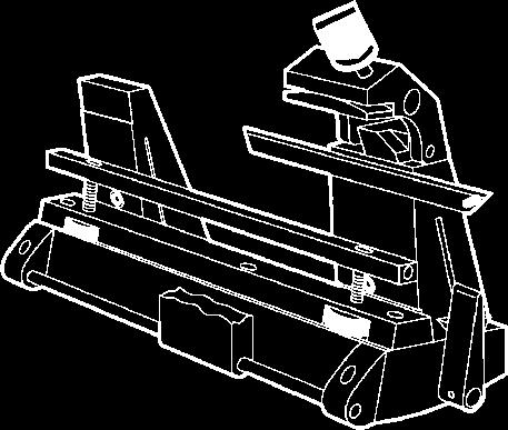
20 5. Setup 5.3 Leica CM Overview Instruction Manual V2.0 03/2001
21 5. Setup Cryostat CM Waste container 3 Control panel 1 4 Control panel 2 5 Storage shelf, left 6 Storage shelf, right 7 Automatic mains fuse 8 Support for stationary heat extractor (accessory)* 9 Quick freeze shelf 10 Peltier element (accessory) 11 Parking station (accessory)* 12 Stationary heat extractor (accessory)* 13 Specimen disc 14 Thermal bloc (accessory) 15 Section waste tray 16 Brush shelf 17 Orientable specimen head 18 Knife holder base (accessory) 19 Knife holder CE (accessory) 20 Knife holder CN (accessory) 21 Knife holder CS (accessory) *)included in the standard delivery range of models with Peltier element Leica CM1850 Cryostat 21
22 5. Setup 5.4 Mains switch and automatic mains fuse Fig. 22 Automatic mains fuse The automatic mains fuse is used as mains switch. To turn the automatic mains fuse on, the switch must be set in the upper position (pos. 1). To turn the automatic mains fuse off, the switch must be set in the lower position (pos. 0). 5.5 Turning the instrument on After transporting, wait at least 4 hours before turning the instrument on. This waiting period is necessary to allow the compressor oil, which may have been displaced during transport, to return to its original position. Failure to comply with this can cause severe damage to the instrument. Turn the instrument on with the automatic mains fuse. The instrument has been configured ex works as follows: Time: 00:00 Defrost time: 10:00 Cryochamber cooling: On (Indication of the temperature) Peltier element (option): Off Indication PE without Peltier element: Indication LL Set the desired values as described in the sections to During normal operation pressure compensation prior to the compressor start-up might lead to a hissing sound. 22 Instruction Manual V2.0 03/2001
23 6. Control panel operation 6.1 Control panel 1 Fig. 23 Function keys Lamp button ON/OFF switch for cryochamber illumination. Manual defrost button To activate and deactivate manual defrosting. Key button To lock and unlock the control panel to protect the entered parameters from unintended modifications. To lock or unlock, hold down for approximately 5 seconds. 6.2 Programming the desired values Setting the time The actual time is set on the panel marked with the clock symbol using the and keys. When pushing the or button for more than 1 second, the time value increases or decreases continuously (autorepeat function). Leica CM1850 Cryostat 23
24 6. Control panel operation Setting the automatic defrost time (cryochamber) The automatic defrost cycle takes place once within 24 hours. Touch the or button for indication of the beginning of the defrost cycle which has actually been set. At the same time, the LEDs between the indication of hours and minutes are flashing. To change the beginning of the defrost cycle in steps of 15 minutes, push the or button Selecting the cryochamber temperature The temperature of the cryochamber is set and indicated on the panel marked with the cryostat symbol. The actual temperature is the standard indication. For indication of the desired value, touch the or button. Set the desired value with the and buttons. When pushing the or button for more than 1 second, the chamber temperature value increases or decreases continuously. The actual value will be indicated 5 seconds after finishing the programming. 24 Instruction Manual V2.0 03/2001
25 6. Control panel operation Activation of the Peltier element (option) The Peltier element is used for cooling the quick-freeze stations. Upon activation of the Peltier element, the compressor of the cooling system is started after 40 seconds to reinforce the thermal conductivity effect. Display reading of instruments without Peltier element: LL with Peltier element: PE The Peltier element is activated by pressing. Once activated, the display indication changes to 10 (i.e. the Peltier element will operate for 10 minutes). The countdown of the remaining cooling time is permanently displayed. The Peltier element turns off automatically after 10 minutes. Once the remaining cooling time displayed is 4 minutes, the figure 4 is followed by a point ( 4. ). At this stage the Peltier element may be deactivated by pressing again. Once deactivated, the display indication returns to PE Manual defrosting of the quick freeze shelf The quick freeze shelf may become hot during defrosting! Therefore, do not touch it! The manual defrosting of the quick freeze shelf is activated by subsequently pressing the button (audible signal turns on) and the key (audible signal turns off). During the defrost cycle, the indication is flashing. To turn off the manual defrosting cycle of the quick freeze shelf prior to the automatic deactivation, press again and. Quick freeze shelf and cryochamber defrosting can be run independently. However, it is not possible to defrost both systems simultaneously. Leica CM1850 Cryostat 25
26 6. Control panel operation Manual defrosting of the cryochamber The manual defrosting of the cryochamber is activated by subsequently pressing the button (audible signal turns on) and the or button on the panel for the cryochamber temperature (audible signal turns off). During the defrost cycle, the indication is flashing. If you want to turn off the manual defrosting of the quick freeze shelf prior to the automatic deactivation, press again and or on the panel for the cryochamber temperature. 6.3 Display lock The programmed values cannot be modified after having pushed the key button. Push the key button once more for 5 seconds to unlock the display. When the display is locked, the LEDs between the hour and minute indication on the time panel are turned off. 26 Instruction Manual V2.0 03/2001
27 6. Control panel operation 6.4 Control panel 2 - Electric coarse feed Move the specimen away from the knife Press to start a rapid return travel of the specimen to the rear limit. LED (1) flashes, while the specimen head is in motion. On reaching the rear limit, the LED (1) starts illuminating. 1 The return movement can be stopped by pressing one of the coarse feed buttons. Press to start a slow return movements of the specimen to the rear limit. The specimen will slowly move to the rear limit, as long as the button is held down. 2 slow Move the specimen towards the knife Press to start a rapid or slow advance of the specimen towards the knife. The advance movement operates as long as the button is pressed. This is a safety feature to protect both the specimen and knife from damage! On reaching the front limit, the LED (2) of the button starts illuminating. rapid Leica CM1850 Cryostat 27
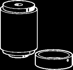
28 7. Daily use of the instrument 7.1 Specimen freezing Quick freeze shelf Select the appropriate sectioning temperature (cryochamber temperature) for the sample material (please refer to 7.4 Temperature selection chart ). 1 The cryochamber has a quick freeze shelf (5, Fig. 28) for up to 10 specimen discs. The temperature of the quick freeze shelf is always lower than the cryochamber temperature. 2 5 Cut the specimen to size. Activate the Peltier element (4) (option), if available - it may take up to 40 seconds until the maximum refrigeration output is available. Apply enough cryocompound to a specimen disc at room temperature. Place the specimen on the disc and orient. Place the specimen disc in one of the holes of the quick freeze shelf and freeze the specimen at a low temperature. Once the specimen is frozen, insert the specimen disc in the specimen head (Fig. 29) and start sectioning. Fig Stationary heat extractor (accessory)* Fix the support (1) of the heat extractor (2) by tightening the 2 screws to the threaded holes on the left sidewall of the cryochamber and insert the heat extractor. Lower the heat extractor cylinder on the specimen surface. After approximately 30 seconds contact, the specimen will be entirely frozen. Once the specimen is frozen, place the heat extractor on the parking station (3). *) included in models with Peltier element 28 Instruction Manual V2.0 03/2001
29 7. Daily use of the instrument 7.2 Specimen discs Inserting the specimen discs in the specimen head Lock the handle of the handwheel in the upper position. If the knife holder and a knife are in place, cover the knife edge with the knife guard. Loosen the screw (1) on the specimen head. Insert the shaft of the specimen disc (3) in the location hole (2) of the specimen head. Make sure that the shaft of the specimen disc is fully inserted. The entire rear surface of the prism must have a good contact with the specimen head. Retighten screw (1) Specimen orientation To release, loosen screw (4). Orient the specimen surface with lever (5). Retighten screw (4). Leica CM 1850 Cryostat 29
30 7. Daily use of the instrument 7.3 Sectioning All necessary adjustments on the knife holder and anti-roll guide are described in the separate instruction manual for your knife holder in detail Trimming the specimen Take care when handling microtome knives and disposable blades. The cutting edge is extremely sharp and can cause severe injury! Insert the precooled knife/blade in the knife holder and clamp. Adjust the appropriate clearance angle on the knife holder. Adjustments between 4 and 6 (knife holder CN and CS) or between 1 and 2 (knife holder CE) are suitable for most applications. Align the knife holder/knife with the specimen. Remove the knife guard (knife holder CN, CS) or fold the glass anti-roll guide (knife holder CE) over to the left. Unlock the handwheel. Trim the specimen to shape approach the specimen towards the knife by means of the coarse feed buttons. Trim the specimen down to the required sectioning plane by turning the handwheel. Position the anti-roll guide on the knife and align with the cutting edge. Readjust the anti-roll plate if necessary Section thickness setting The section thickness is adjusted in a range of 1 to 60 µm by turning the knob (1): f rom 0-10 µm in 1 µm increments, from µm in 2 µm increments, from µm in 5 µm increments. The selected section thickness is indicated on the index mark on the microtome. Select the required section thickness with the control knob on the microtome. Start sectioning at approximately 20 µm. Decrease the section thickness continually down to the appropriate value. After changing from one section thickness to another, the first two or three sections should be rejected. When sectioning, turn the handwheel at a constant speed. 30 Instruction Manual V2.0 03/2001
31 7. Daily use of the instrument 7.4 Temperaturew selection chart (in minus C) Tissue Adrenal Bone marrow Brain Bladder Breast - fatty Breast - little fat Cartilage Cervical Fatty Heart and vascular Intestinal Kidney Laryngeal Lip Liver Lung Lymphoid Muscular Nose Pancreatic Prostate Ovarian Rectal Skin with fat Skin without fat Spleenal or bloody tissue Testicular Thyroid Tongue Uterus curettage The temperature values given above are based on long-term experience, however, these are only approximate values, as any tissue may require particular adjustments. Leica CM1850 Cryostat 31
32 7. Daily use of the instrument 7.5 Defrosting Defrosting the cryochamber actually means defrosting the evaporator to prevent excessive frost buildup. The evaporator is flushed with hot gas during defrosting. The cryochamber virtually is frostfree and does not need to be defrosted. The condensation water that is produced during defrosting is collected in a container, which is located at the front of the cryostat cabinet. To make sure that the condensation water stemming from the defrost cycles drains into the waste container and to avoid the risk of possible contaminations, ensure that the tap of the waste container (2, Fig. 41) is open when operating the instrument. Only shut the tap when draining the waste container! Automatic defrosting of the cryochamber Manual defrosting of the cryochamber The quick freeze shelf is cooled during the automatic cryochamber defrosting. However, the Peltier element is turned off.the maximum duration of a defrost cycle is 12 minutes. Defrosting is terminated automatically once the cryochamber has reached a temperature of -5 C. Cooling turns back on automatically. An automatic defrost cycle takes place once in 24 hours. The time of the automatic defrost cycle is programmed via the control panel 1 (see and 6.2.2). In addition to the programmable automatic defrost cycle a manual defrost cycle can be activated (see also 6.2.6). To avoid an unintended defrosting, the activation of a manual defrost cycle is confirmed by an audible signal. Cooling turns back on automatically. 32 Instruction Manual V2.0 03/2001
33 7. Daily use of the instrument Manual defrosting of the quick freeze shelf 7.6 Terminating work Terminating daily work The quick freeze shelf may become hot during defrosting! Therefore, do not touch it! If increased frost formation occurs on the quick freeze shelf, especially after spray disinfection, a manual defrost cycle should be started (see 6.2.5), which can be terminated when required. Lock the handwheel. Take the knife out of the knife holder and put it back into the knife box in the cryochamber. Remove frozen section waste with a cold brush. Empty the section waste tray. Clean the storage shelves and brush shelf. Only common detergents and disinfectants that contain % alcohol should be used for cleaning. All components removed from the cold environment will collect condensation. Therefore, dry them thoroughly before placing them back into the cryochamber. Remove all specimens from the cryostat. Close the sliding window. Turn out the cryochamber illumination. Lock control panel 1 (Fig. 23) with the KEY button. Do not turn the instrument off with the automatic mains fuse as there would be no cooling. Leica CM1850 Cryostat 33
34 8. Troubleshooting Shutdown for a longer period If you do not intend to use the instrument for several weeks you may turn it off. Please note, however, that it may take up to several hours to cool the cryochamber down to very low temperatures after turning the instrument on again. After turning off, the instrument should be cleaned and disinfected thoroughly (see chapter 9 Cleaning, disinfection and maintenance'). Turn the instrument off with the automatic mains fuse. Open the sliding window to allow the cryochamber to dry. Remove all the specimens from the cryostat. Lock the handwheel. Take the knife/blade out of the knife holder. Put the knife back into the knife box or push the blade into the receptacle for used blades provided at the bottom of the dispenser. Remove all section waste with a cold brush. Empty the section waste tray and remove it for cleaning and disinfection. Remove the storage shelves and the brush shelf for cleaning and disinfection. Turning off the instrument with the automatic mains fuse will not affect the programmed parameters. Before turning the instrument on again, the cryochamber microtome and all accessory components must be absolutely dry. 34 Instruction Manual V2.0 03/2001

 24 Short circuit at the temperature sensor Call service. of the chamber cooling system. 25 Breaking of the temperature sensor Call service.")
35 8. Troubleshooting 8.1 Error messages in the display Error messages are displayed on the clock panel as follows: EO: XX. The following error messages might occur during operation: Error Description Remedy 20 Calibrating error; possibly defective controller board. Turn the instrument on again. If the error is displayed again: Call service. 21 Clock battery on the controller board empty. Call service. 22 Microtome wet. Dry microtome. 23 Cryochamber temperature out of range of indication. Remove cause. (from -35 C to +55 C) 24 Short circuit at the temperature sensor Call service. of the chamber cooling system. 25 Breaking of the temperature sensor Call service. of the chamber cooling system. 26 Short circuit at the temperature sensor of the evaporator. Call service. 27 Breaking of the temperature sensor of the evaporator. Call service. 8.2 Temperature control button On the back of the cryostat cabinet there is a temperature control button (1). If the temperature of the cryochamber exceeds 60 C the switch is automatically activated and turns the instrument off. Possible causes and remedies: Fig. 35 Temperature of the direct surroundings is constantly higher than 40 C. -->Drop the temperature of the direct surroundings. When setting up the instrument the minimum distance of 10 cm to walls and furniture was not kept. --> Keep the minimum distance. The ventilation slits of the liquefier are dirty. --> Clean the ventilation slits (see 9.3.1). After eliminating the possible source of error, push the temperature control button (1) to turn the instrument back on. If the instrument fails to turn on, make a service call. Leica CM 1850 Cryostat 35
36 8. Troubleshooting 8.3 Possible causes and remedies Problem Cause Remedy Frost on chamber walls and microtome Ice formation on the bottom of the cryochamber Sections smear Sections splinter Sections not properly flattened -Cryostat is exposed to air currents (open windows and doors, air conditioning). -Sliding window was open and exposed to air currents too long. -Frost built up by breathing into the cryochamber. -Condensation water drain obstructed. -Drain of the quick freeze shelf defrosting water obstructed. -Specimen not cold enough. -Knife/blade and/or anti-roll plate not yet cold enough and thus warm the sections. -Specimen too cold -Static electricity/air currents. -Specimen not cold enough. -Large area specimen. -Anti-roll plate poorly positioned. -Anti-roll plate poorly aligned with knife edge. -Incorrect clearance angle. -Knife/blade blunt or damaged. -Change place of installation for the cryostat. -Open the tap of the drain tube (2, Fig. 31), switch off the instrument and let it thaw and dry. -Align the instrument with a spirit level. -Select lower temperature. -Wait until knife/blade and/or anti-roll plate have reached chamber temperature. -Select higher temperature. -Remove cause. -Select lower temperature. -Trim the specimen parallel, increase section thickness. -Reposition anti-roll plate. -Align correctly. -Set correct angle. -Use different part of the cutting edge or replace. 36 Instruction Manual V2.0 03/2001
37 8. Troubleshooting Problem Cause Remedy Sections not properly flattened despite correct temperature and correctly aligned anti-roll plate Sections curl on the anti-roll plate Scraping noise during sectioning and specimen return movement Ridged sections Chatter during sectioning -Knife/blade and/or anti-roll plate dirty. -Edge of anti-roll pate damaged. -Blunt knife/blade. -Anti-roll plate does not protrude far enough beyond the cutting edge. -Anti-roll plate protrudes too far beyond the cutting edge and is scraping against the specimen. -Knife/blade damaged. -Edge of anti-roll plate damaged. -Specimen insufficiently frozen onto the specimen disc. -Specimen disc not clamped tightly. -Specimen holder ball joint not clamped. -Knife/blade not clamped tightly enough. -Specimen has been sectioned too thickly and has detached from the disc. -Very hard, inhomogeneous specimen. -Blunt knife/blade. -Clean with dry cloth or brush. -Replace plate. -Use different part of the cutting edge or replace. -Readjust correctly. -Readjust correctly. -Use different part of the cutting edge or replace. -Replace the plate. -Refreeze specimen onto the disc. -Check disc clamping. -Check ball joint clamping. -Check knife/blade clamping. -Refreeze specimen onto the disc. -Increase section thickness; reduce specimen surface area if necessary. -Use different part of the cutting edge or replace the knife/ blade. Leica CM1850 Cryostat 37
38 8. Troubleshooting Problem Cause Remedy Condensation on anti-roll plate and knife during cleaning Anti-roll plate damage after adjustment Thick-thin sections Tissue sticks or crumbles on the anti-roll plate -Knife profile inappropriate for the specimen to be cut. -Incorrect clearance angle. -Brush, forceps and/or cloth are too warm. -Plate too high above the cutting edge. The adjustment was carried out in the direction of the cutting edge. -Temperature incorrect for the tissue cut. -Knife profile inappropriate for the specimen cut. -Ice buildup in the knife back. -Handwheel speed not uniform. -Knife/blade not clamped tightly enough. -Specimen holder not clamped tightly. -Cryocompound applied to cold specimen disc; specimen detached from the disc after freezing. -Blunt cutting edge. -Incorrect clearance angle. -Microtome not properly dried before reinstallation. -Dried specimen. -Anti-roll plate is too warm or incorrectly positioned. -Static electricity. -Use knife with different profile. -Set correct angle. -Store all tools on shelf in the chamber. -Raise plate when aligning. -Be more careful next time. -Select correct temperature. -Wait until the correct temperature is reached. -Use knife with different profile (c or d). -Remove ice. -Adapt speed. -Check knife/blade clamping. -Check clamping. -Apply cryocompound on warm disc; mount specimen and freeze. -Use different part of the cutting edge or replace the knife/ blade. -Set correct angle. -Dry microtome thoroughly. -Prepare new specimen. -Cool down anti-roll plate or reposition plate. -Remove static electricity. 38 Instruction Manual V2.0 03/2001
39 Problem Cause Remedy 8. Troubleshooting Flattened sections curl up when anti-roll plate is picked up Sections tear Inconsistent or insufficient specimen feed Specimen disc cannot be removed Cryostat inoperational Fat on the corner or edge of the anti-roll plate. -Rusty knife/blade. -Static electricity or air currents. -Anti-roll plate too warm. -Temperature too low for the tissue cut. -Blunt part, dirt, dust, frost or rust on the knife/blade. -Leading edge of anti-roll plate damaged. -Hard particles in the tissue. -Knife back dirty. -Microtome was not entirely dry when switching on refrigeration; consequently ice built up in the micrometer feed system. -Defective microtome. -Moisture on the underside caused the disc to freeze to the freezing shelf or specimen head. -Mains plug not properly connected. -Defective fuses. -Temperature control switch activated. -Remove fat with alcohol. -Remove rust. -Remove static electricity. -Cool down the anti-roll plate. -Increase temperature and wait. -Remove cause. -Replace the plate Clean. -Remove the microtome and dry it thoroughly before reinstallation. -Call technical service. -Apply concentrated alcohol to the contact point or heat the specimen head. -Check the mains plug is properly connected. -Replace the fuses. -Check site conditions as described in section 5.2, and reset the temperature control switch. Leica CM1850 Cryostat 39
40 8. Troubleshooting Problem Cause Remedy No or insufficient refrigeration Scraping noise at the microtome -Compressor defective. -Leak in the cooling system. -Inappropriate site conditions. -Ventilation slits of the liquefier dirty. -Friction between the slot cover and the microtome housing. -Call technical service. -Call technical service. -Check site conditions as described in section Clean the ventilation slits as described in section Apply cryostat oil to the slot cover and distribute by turning the handwheel or with a cloth. 40 Instruction Manual V2.0 03/2001
.")
41 9. Cleaning, disinfection, maintenance 9.1 Cleaning Remove frozen section waste from the cryostat with a cold brush every day. Remove the section waste tray for emptying. Remove the storage shelves and the brush shelf for cleaning. Remove the sliding window by slightly lifting and pulling it to the front when closed (see 'Replacement of the lamp'). Do not use organic solvents or any other aggressive substances for cleaning and disinfecting! Only use the cleaning agents specified in this instruction manual such as Leica Cryofect (alcohol or common disinfectants based on alcohol)! Drain the cleaning liquid through the hose after the prescribed reagent time is over and collect it in the waste container (1). 2 3 Dispose of the waste liquid according to the waste disposal regulations. To remove the waste container (1), shut off the tap (2) and unscrew the lid (3). 1 Condensation water produced during defrosting collects in the waste container. Therefore, check the liquid level regularly and empty the container if necessary. Leica CM 1850 Cryostat 41
42 9. Cleaning, disinfection, maintenance 9.2 Spray disinfection with Leica Cryofect For easy-to-use spray disinfection we recommend Leica Cryofect. The cryostat has to be disinfected after each daily use. Comply with the instructions for use! The glass anti-roll plate can remain in place during disinfection. 1. Select a cryochamber temperature value down to -20 C. 2. Remove the knife or blade from the knife holder. 3. Remove all samples, microscope slides and tools from the cryochamber. 4. Remove debris from the cryochamber. Allow the cryochamber to reach the previously selected temperature. Once the selected temperature is reached, either 5a. spray the disinfectant evenly on the contaminated surfaces- the surfaces should be covered with an even layer - or 5b. soak a cloth with disinfectant and apply it on the contaminated surfaces. 6. Allow a reaction time of no less than 15 minutes. 7. Wipe it off with a tissue. 8. Dispose of tissue in compliance with the ruling waste disposal regulations of your institution. 9. Set the cryochamber temperature to the originally selected value. If increased frost buildup occurs, start a manual defrost cycle. 42 Instruction Manual V2.0 03/2001

43 9.3 Maintenance General maintenance 1 9. Cleaning, disinfection, maintenance The microtome is virtually maintenance-free. To ensure a smooth operation of the instrument over several years we recommend the following: Have the instrument inspected by a qualified service engineer authorized by us once a year. Enter into a service contract at the end of the warranty period. For further information, please contact your local Leica service center. Clean the instrument every day. Fig Once a week: Apply a drop of oil to the plastic coupling (5, Fig. 45.2). Fig Lubricate the specimen cylinder (1): Push the appropriate coarse feed button to move the specimen cylinder out to the front stop position, apply a drop of cryostat oil and move the specimen cylinder back to the home position by pressing the appropriate coarse feed button. Occasionally, or when required: Lubricate the clamping piece (T-piece) (2) on the microtome base plate and the clamping lever (3). Lubricate the slot cover (4). To do so, turn the handwheel to place the specimen head to the uppermost position and apply some drops of cryostat oil on to the slot cover; after that place the specimen head to Leica CM 1850 Cryostat 43
44 9. Cleaning, disinfection, maintenance Removal of the microtome the lowest position and apply some drops of cryostat oil on to the slot cover; distribute the applied oil by turning the handwheel or with a soft tissue. Clean the ventilation slits (5) of the liquefier on the right side of the instrument with a brush, broom or vacuum cleaner from dust and dirt in the direction of the fins. Do not carry out any repairs on your own as this will invalidate the warranty. Repairs may only be carried out by qualified service engineers authorized by Leica. The microtome can be removed for thorough cleaning and disinfecting, or for extensive drying after a long power failure! Turn the instrument off and disconnect the mains plug before removing the microtome. Prior to removing the microtome, place the specimen head to the lowest position by placing the handle of the handwheel in the lowest position. When removing the microtome, the specimen head will rapidly fall down and might injure the operator s hands. Wear appropriate protective gloves to take the cold microtome out of the cryochamber! Extended skin contact with cold parts of the instrument may cause frost bite! Slightly lift the sliding window when closed holding it at the grip provided and pull it out to the front (Fig. 49.1) - see Replacement of the lamp. Remove the accessories in the following order: brush shelf, knife holder, section waste tray, specimen discs, stationary heat extractor, left storage shelf, right storage shelf. 44 Instruction Manual V2.0 03/2001
45 Cleaning, disinfection, maintenance Loosen the screws (3) with an Allen key (4 mm). Do not loosen the screws (7) for removing the microtome. Disconnect the coarse feed motor plug (1) by pulling the metal head. 1 3 Disconnect the temperature sensor (2) from the microtome. 8 8 Fig Slightly lift the microtome and pull it to the left to disengage the plastic coupling (5) connecting the axes. Take the microtome out of the cryochamber. Fig Leica CM 1850 Cryostat 45
46 9. Cleaning, disinfection, maintenance Removal of the microtome cover 8 8 The microtome cover may be removed to expeditethorough drying of the microtome in an oven. Note: Place the microtome in an oven at 40 C to 50 C for several hours. After repeatedly drying the microtome in this manner, it may become necessary to relubricate the cross roller bearings! For further information, please contact your sales company! Fig Loosen the two screws (8) on both sides of the cover. To remove, pull the cover upwards. The front plate of the microtome with the specimen head remains in place. Do not use external heaters for drying the cryochamber! This can cause damage to the cooling system! Reinstallation of the microtome Place the microtome slightly left from the original position into the cryochamber. Make sure that the specimen head is in the lowest position. Lubricate the surface of the plastic coupling (5) with a drop of cryostat oil. Mount the plastic coupling (5) on the shaft (4). Use your right hand to bring the handwheel handle in the lowest position and keep the handle in place. The specimen head remains in the lower position. 46 Instruction Manual V2.0 03/2001
47 9. Cleaning, disinfection, maintenance Ensure that the microtome is completely dry before reinstallation. Humidity inside will condense and freeze and thus cause malfunctions or damage to the feed system of the microtome. 2 Use your right hand to bring the handwheel handle in the lowest position and keep the handle in place. The specimen head remains in the lower position. Push the microtome to the right with your left hand, and, if necessary, turn the handwheel back and forth to ensure proper alignment of the parts until the plastic coupling (5) engages to the shaft (6). Tighten the screws (3). Reconnect the coarse feed motor plug (1) and the temperature sensor (2). Replace the storage shelves, heat extractor, brush shelf and knife holder in the cryochamber. Replace the sliding window Fig Fig Ensure that all components removed from the cold environment are completely dry before placing them back into the cryochamber. Leica CM 1850 Cryostat 47

48 9. Cleaning, disinfection, maintenance Replacement of the fuses Turn the instrument off with the automatic mains fuse and pull the mains plug, before replacing the fuses! Only use fuses of the same specification! For the required values, please refer Chapter 3 Technical Data. The use of fuses other than specified by the manufacturer may cause severe damage to the instrument! On the back of the instrument there is a fuse box with 5 fuses: Fuse Protection Type Unscrew the fuse cap with a screwdriver. Remove both fuse cap and fuse. Put the new fuse in the cap and screw the fuse cap back on. F1 Display T 0.25 A F2 Coarse feed T 0.6 A F3 Processor board supply T 1.6 A F4 Peltier element T 6.25 A F5 Heaters T 4 A Replacement of the lamp Turn the instrument off with the automatic mains fuse and pull the mains plug, before replacing the lamp! If the lamp is broken, it must be replaced by the technical service, as the replacement involves a high risk of injury. 48 Instruction Manual V2.0 03/2001
TN2085 Cryostat Semi-Automatic Cryostat
 User Manual TN2085 Cryostat Semi-Automatic Cryostat Read Prior to Operation! Always keep this manual near the unit! WP47113 06.02.15 User Manual TN2085-Cryostat 888.708.5233 Info@TannerScientific.com
Leica CM1100. Cryostat
 Leica CM1100 Cryostat Instructions for use Leica CM1100 V1.3 RevB English 09/2012 Order-No.: 14 0469 80101, RevB Always keep this manual near the instrument! Read carefully prior to operating the instrument!
OPERATING INSTRUCTIONS
 OPERATING INSTRUCTIONS Cryostat MNT INS2500GB 2011-08-09 Instructions MNT 1 Instructions MNT 2 CONTENTS 1. INTENDED USE... 4 2. SYMBOLS... 4 3. SAFETY NOTES... 4 4. COMPONENTS... 9 5. SPECIFICATIONS...
Overview. rotary microtomes
 rotary microtomes Overview All SLEE microtomes are produced at the company s seat in Mainz, Germany. The highly precise, modularly built rotary microtomes range from a manual unit, type CUT 4062, via the
Thermo Scientific HM525 NX Operator Guide Issue 2.0
 Thermo Scientific HM525 NX Operator Guide 388159 Issue 2.0 Company Information 2 Thermo Scientific HM525 NX Company Information Company Information Copyright 2013. Thermo Fisher Scientific Inc. All rights
Thermo Scientific CryoStar NX70 / NX50 Operator Guide
 Thermo Scientific CryoStar NX70 / NX50 Operator Guide 387928 Legal Information Copyright 2011. Thermo Fisher Scientific. All rights reserved. Thermo Fisher Scientific is an ISO 9001 Company. Thermo Fisher
Thermo Scientific CryoStar NX50 Operator Guide Issue 2.0
 Thermo Scientific CryoStar NX50 Operator Guide 388149 Issue 2.0 Company Information 2 Thermo Scientific NX50 Company Information Company Information Copyright 2013. Thermo Fisher Scientific Inc. All rights
OTF5000 Cryostat. At the cutting edge of sectioning technology
 OTF5000 Cryostat At the cutting edge of sectioning technology Bright Introduction Based on the long-established and reliable OTF/AS cryostat, the new OTF5000 brings Bright cryostats completely up to date.
POLYMIX PX-IG 2000 Operating Instructions
 POLYMIX PX-IG 2000 Operating Instructions Voltage D 100-120V, 50/60 Hz D 210-250V, 50/60 Hz Please check that the voltage is correct and corresponds with the nameplate on the back of the machine. Manual
Technical Data. Name: ERIKA Automat fully automatic machine to divide and to round dough pieces of the same size
 AUTOMAT MANUAL 1 Technical Data Name: ERIKA Automat fully automatic machine to divide and to round dough pieces of the same size Type Divisions Dough Portions (in ounces) Plate Nos. 3 30 1.0 3.5 #35 4/40A
SECTION TRANSFER SYSTEM STS. for ROTARY MICROTOMES INSTRUCTION MANUAL. Section Transfer System
 SECTION TRANSFER SYSTEM STS for ROTARY MICROTOMES INSTRUCTION MANUAL 1 2 CERTIFICATION certifies that this instrument has been tested and checked carefully. Its technical data was verified before shipment
OPERATING MANUAL Gfp 255C Please read this manual carefully before operating!
 OPERATING MANUAL Gfp 255C Please read this manual carefully before operating! Unpacking, assembly, and operating videos are available at www.gfpsmoothstart.com 1 Table of Contents Gfp 255C March 2015 Contents
User Manual. TN1500 Embedding Center. Read Prior to Operation! Always keep this manual near the unit! WP
 User Manual TN1500 Embedding Center Read Prior to Operation! Always keep this manual near the unit! WP46818 06.02.15 User Manual TN1500-Embedding Center 888.708.5233 Info@TannerScientific.com www.tannerscientific.com
Instructions manual DEHUMID HP50
 Instructions manual DEHUMID HP50 Table of contents 1. Unpacking 3 2. Intended use 3 3. Disposal 3 4. Safety instructions 3 5. Functional principle 4 6. Automatic defrosting system 4 7. Set up and transportation
Before Putting Into Use. Important. Tips for Energy Savings
 Before Putting Into Use Before connecting the appliance to the power supply, let it stand for about 2 hours, which will reduce a possibility of malfunctions in the cooling system due to transport handling.
Local Air Conditioner
 Local Air Conditioner Thank you for selecting this air-conditioner. Please keep this User s Manual for future reference. Read the User s Manual carefully before operating this unit. IMPORTANT SAFEGUARDS
Installation and Operating Instructions DÜRR Regeneration Unit for X-ray developers XR 24, XR24 II, XR 24 Nova, XR 24 Pro
 Installation and Operating Instructions DÜRR Regeneration Unit for X-ray developers XR 24, XR24 II, XR 24 Nova, XR 24 Pro 2006/01 Content Important Information 1. Notes... 3 1.1 CE - Labeling... 3 1.2
Operating instructions Page 12
 Operating instructions Page 12 Refrigerator with explosion-proof interior container Read the operating instructions before switching on for the first time 7082 271-00 LKEXv 910 Disposal notes The appliance
WARNING: Warns of health hazards and identifies possible risks of injury. CAUTION: Indicates possible dangers to the machine or other objects.
 VBT3ASV USER GUIDE SAFETY INFORMATION About this user guide Read this user guide completely before using the machine. Keep this user guide for reference. If you pass your machine on to third parties, it
For Models FF2310APS, FF2310APW, FF2310APB 55cm FREESTANDING FRIDGE FREEZER. Instruction Manual
 For Models FF2310APS, FF2310APW, FF2310APB 55cm FREESTANDING FRIDGE FREEZER Instruction Manual Please read these instructions carefully before use and retain for future reference. Before switching on your
Operating and Maintenance Instructions
 EATON Germany GmbH Werk Lohmar D-53797 Lohmar Operating and Maintenance Instructions WALFORM Machine Electronically controlled - Conforms to CE MEG-WF385X Status: Sept 2011 MEG-WF385X_Stand Sept 2011 SUITABILITY
INSTRUCTION MANUAL HETO CBN 8 / 18 / C Cooling Baths ID: IM.doc Revision 1
 Revision 1 INSTRUCTION MANUAL HETO CBN 8 / 18 / 28-30 - 30 C Cooling Baths ID: 88872215 Page 2 / 9 INSTRUCTION MANUAL CBN 8 / 18 / 28-30 Important user information Please read this entire manual to fully
ASG EZ-9000GR Tape Dispenser User Manual ASG #66136
 ASG EZ-9000GR Tape Dispenser ASG #66136 Revision Date: 03/27/18 1 Read Before Use Warnings and Cautions The safety guidelines in this instruction manual must be observed in order to prevent injury to the
Operating Instructions. Accessory Units Melitta Cafina XT Series. Melitta Professional Coffee Solutions
 Operating Instructions Accessory Units Melitta Cafina XT Series Melitta Professional Coffee Solutions Contents General... 4. Manufacturer information... 4.2 About these instructions... 4.3 Explanation
OPERATING INSTRUCTIONS
 OPERATING INSTRUCTIONS Automatic Carousel Stainer MSM INS5000GB 2011_08_07 Instructions MSM 1 Instructions MSM 2 CONTENTS 1. INTENDED USE... 4 2. SYMBOLS... 4 3. SAFETY NOTES... 4 4. COMPONENTS... 5 5.
User Manual. Chest Freezer ZFC26500WA
 EN User Manual Chest Freezer ZFC26500WA Contents Safety information 2 Safety instructions 3 Operation 5 Before first use 5 Daily use 5 Hints and tips 6 Care and cleaning 7 Troubleshooting 8 Installation
TTK 75 ECO OPERATING MANUAL DEHUMIDIFIER TRT-BA-TTK75ECO-TC-002-EN
 TTK 75 ECO EN OPERATING MANUAL DEHUMIDIFIER TRT-BA-TTK75ECO-TC-002-EN Table of contents Notes regarding the operating manual... 01 Information about the device... 02 Safety... 04 Transport...05 Start-up...05
Operating Manual. VIENNA Hot Display
 Operating Manual VIENNA Hot Display Operating and Maintenance instructions Please read this manual carefully before you start to operate your heated display case. Following these instructions helps you
Part 2: Installation Instructions cl
 Contents Page: Part 2: Installation Instructions cl. 381-382 1. Delivery scope............................... 3 2. General and Transportation safety precautions........... 3 3. Stand installation 3.1 Installing
Bedienungsanleitung. Ideas for dental technology. Made in Germany C
 Bedienungsanleitung 216604 C 01022013 Made in Germany Ideas for dental technology GLISH Instruction manual 1. Introduction...1 1.1 Employed Symbols...1 2. Safety...2 2.1 Intended use...2 2.2 Improper use...2
User Manual GV25 GV35 GV702. Company information: Original instructions GV12066 (1)
") User Manual Original instructions GV25 GV35 GV702 Company information: www.vipercleaning.eu info-eu@vipercleaning.com GV12066 (1) 2012-04-10 USER MANUAL ENGLISH TABLE OF CONTENTS Introduction... 4 Manual
User Manual Original instructions GV25 GV35 GV702 Company information: www.vipercleaning.eu info-eu@vipercleaning.com GV12066 (1) 2012-04-10 USER MANUAL ENGLISH TABLE OF CONTENTS Introduction... 4 Manual
Industrial Vacuums, Inc
 Instructions/Spare Parts Manual Nilfisk Model GWD255 Drum Top Vacuum CAUTION: This Nilfisk vacuum cleaner is not to be used in explosion-hazardous areas, as serious injury could result. Under no circumstances
FWC152, FWC303, FWC603 & FWC623 Wine Coolers Installation, Use and Maintenance
 FWC152, FWC303, FWC603 & FWC623 Wine Coolers Installation, Use and Maintenance Customer Care Department The Group Ltd. Harby Road Langar Nottinghamshire NG13 9HY T : 01949 862 012 F : 01949 862 003 E :
Before Putting Into Use. Important. Tips for Energy Savings
 Before Putting Into Use Before connecting the appliance to the power supply, let it stand for about 2 hours, which will reduce a possibility of malfunctions in the cooling system due to transport handling.
Ui REFRIGERATOR SPEC SHEET
 Ui REFRIGERATOR SPEC SHEET ISOMETRIC VIEW 19 7/8 20 1/2 32 3/4 FRONT VIEW NOTES: 1. CUTOUT DIMENSIONS: 20 1/2"W X 33"L X 20 3/4"D 2. CUTOUT DIMENSIONS ARE FOR REFRIGERATOR ONLY. REFER TO STAINLESS STEEL
FELIX STORCH, INC. SUMMIT APPLIANCE DIVISION
 FELIX STORCH, INC. SUMMIT APPLIANCE DIVISION INSTRUCTION MANUAL FOR MODEL: FFAR-10 Thank you for your trust and for buying this appliance. It s designed to refrigerate your fresh foods, while adding an
Installation Instructions. Mira LED Light System
 Installation Instructions Mira LED Light System w w w. a m i c o. c o m Contents Symbols Used in This Manual 4 Safety Instructions 5 Variants 7 Scope Of Delivery 8 Installing Mira LED Ceiling Mounted Installing
OPERATING INSTRUCTIONS
 OPERATING INSTRUCTIONS Paraffin Wax Embedding Centre MPS/P2 INS3100GB 03-2011-06 Instructions MPS/P2 1 Instructions MPS/P2 2 CONTENTS 1. INTENDED USE... 4 2. SYMBOLS... 4 3. SAFETY NOTES... 4 4. COMPONENTS...
Millo / Millo pro. Nr x000 / 1805-x000. Ideen für die Dentaltechnik A
 Millo / Millo pro Nr. 1804-x000 / 1805-x000 0609 21-6543 A Ideen für die Dentaltechnik 1 2 3 4 5 6 7 8 9 10 11 12 Millo / Millo pro No. 1804-x000 / 1805-x000 ENGLISH Content Introduction... 15 Symbols...
REFRIGERAT A OR USE DF1-15 F ridge
 REFRIGERATOR USE DF1-15 Fridge BEFORE USING THE APPLIANCE. Your new appliance is designed exclusively for domestic use. To ensure best use of your appliance, carefully read the operating instructions which
Get Cleaning... What s your Vax s model number? User Guide. Carpet Washer Vax Careline: AU: NZ:
 User Guide Vax Careline: AU: 1300 361 505 NZ: 0800 800 900 Carpet Washer Get Cleaning... What s your Vax s model number? W8 W8 W0 W0 W0 W W W W W What s your serial number? (Located on the base of the
for LABORATORY REFRIGERATOR MODEL TELR-145/ L/200L CAPACITY REVISION
 for LABORATORY REFRIGERATOR MODEL TELR-145/200 145L/200L CAPACITY REVISION 10-8-17 Thermoline Scientific Equipment Pty. Ltd. ABN 80 000 859 129 10/12 Ross Place Wetherill Park NSW 2164. P.O. Box 1851 Wetherill
Operating instructions Page 16. Refrigerator Read the operating instructions before switching on for the first time
 Operating instructions Page 16 Refrigerator Read the operating instructions before switching on for the first time EN 7085 413-00 LKPv Content Safety instructions and warnings... 17 Noise emissions from
Hot Chocolate Dispenser
 Hot Chocolate Dispenser Instruction manual Model: CN219-A AU Telephone Helpline: 1300225960 Safety Tips Position on a flat, stable surface. A service agent/qualified technician should carry out installation
NON-CYCLING REFRIGERATED AIR/GAS DRYERS QPNC 75 to QPNC 250 OPERATOR S MANUAL
 NON-CYCLING REFRIGERATED AIR/GAS DRYERS QPNC 75 to QPNC 250 OPERATOR S MANUAL DATE OF PURCHASE: MODEL: SERIAL NO.: Record above information from nameplate. Retain this information for future reference.
GCG-10. Instruction Manual. G-Series Cooler. Manual is for the following models: GCG-10-N33EB G-10-N33EB UPRIGHT COOLER
 G-Series Cooler GCG-10 UPRIGHT COOLER Manual is for the following models: GCG-10-N33EB G-10-N33EB Instruction Manual Manual is for the following models: GCG-10-N33EB G-10-N33EB Instruction Manual GCG-10
Operating instructions Page 14. Refrigerator Read the operating instructions before switching on for the first time
 Operating instructions Page 14 Refrigerator Read the operating instructions before switching on for the first time 7085 039-00 LKv 5710 Content Disposal notes... 14 Description of the appliance... 14 Safety
FWC153, FWC304, FWC604 & FWC624
 FWC153, FWC304, FWC604 & FWC624 Wine Coolers Installation, use and maintenance www.cda.eu Important The CDA Group Ltd cannot be held responsible for injuries or losses caused by incorrect use or installation
WAILEA OWNER S MANUAL
 WAILEA OWNER S MANUAL The blades in each pack are matched for equal weight to assure smooth fan operation. If more than one fan is being installed, be careful not to mix blades from different cartons.
Air always contains a certain amount of water in the form of vapour. This determines the
 Useful information on humidity Air always contains a certain amount of water in the form of vapour. This determines the level of humidity in an atmosphere. The capacity of the air to hold water vapour
Crimping machine RC AS Operating instructions
 Crimping machine RC AS 4050.456 Operating instructions Contents Contents About this documentation... 4 General safety notes... 5. Intended use... 5. Material that can be processed and crimping shape...
TK-1801, TK-1811 TK-1801, TKR-1811
 TK-1801, TK-1811 TK-1801, TKR-1811 Pneumatic Zero Energy Band Room Thermostats General Instructions APPLICATION For proportional control of pneumatically-operated sequenced heating and cooling valves and/or
Operator s Manual. Histology Bath
 Operator s Manual Histology Bath 110-827 05.09.12 Table of Contents Introduction... 2 General Safety Information... 2 Safety Recommendations... 3 Unpacking Your Histology Bath...4 Contents...4 Components
HW-17 Record Cleaning Machine Setup and Instruction Manual
 HW-17 Record Cleaning Machine Setup and Instruction Manual VPI Industries, Inc., 77 Cliffwood Ave. #3B, Cliffwood, NJ 07721 Phone: 732-583-6895, Email: Sales@vpiindustries.com http://www.vpiindustries.com
DOCUMENT CREASING MACHINE
 DOCUMENT CREASING MACHINE OPERATORS MANUAL Morgana Systems Limited Snowdon Drive Winterhill Milton Keynes Buckinghamshire MK6 1AP United Kingdom Telephone: ( 01908 ) 608888 Facsimile: ( 01908 ) 692399
TA-12. Tabbing System USER'S GUIDE
 TA-12 Tabbing System USER'S GUIDE SAFETY PRECAUTIONS THIS EQUIPMENT PRESENTS NO PROBLEM WHEN USED PROPERLY. HOWEVER, CERTAIN SAFETY RULES SHOULD BE OBSERVED WHEN OPERATING THE TA12 TABBER. BEFORE USING
Operating Manual. English. Refrigerators for chemicals KRC 50 KRC 180
 English Operating Manual Refrigerators for chemicals KRC 50 KRC 180 1.951.6610-V1 12/12 JULABO GmbH 77960 Seelbach / Germany Tel. +49 (0) 7823 / 51-0 Fax +49 (0) 7823 / 24 91 info@julabo.de www.julabo.de
User s Guide ENGLISH. Other languages available on our website:
 User s Guide ENGLISH Other languages available on our website: www.gilson.com. 1 SAFETY SYMBOLS USED 3 2 INTENDED USE 3 This equipment generates, uses and can radiate radio frequency energy and, if not
WA A Aqua Sub Bottom-load Water Cooler
 WA1-02-21A Aqua Sub Bottom-load Water Cooler 4002638 Thank you for choosing a Soleus Air Water Cooler. This owner s manual will provide you with valuable information necessary for the proper care and maintenance
CHEST FREEZER INSTRUCTION MANUAL. Model No.: EWCF5WBX EWCF7WBX
 CHEST FREEZER INSTRUCTION MANUAL Model No.: EWCF5WBX EWCF7WBX To ensure proper use of this appliance and your safety, please read the following instructions completely before operating this appliance.
Use and Care Manual. For Beverage Cooler RU
 Use and Care Manual For Beverage Cooler RU 500 7081 619-01 Congratulations on your purchase. Choosing this appliance means you want all the benefits of state-of-the-art refrigeration technology, guaranteeing
Operator Manual NA 9328 Prof XL pump
 Operator Manual Win Equipment B.V. De Kronkels 31 3752 LM Bunschoten The Netherlands Tel.: +31 (0)33 299 22 66 Fax: +31 (0)33 299 22 50 E-mail: info@winequipment.nl Translation of the Original Instructions
WHYNTER Compressor Cooling Beverage Refrigerator - Stainless Steel
 WHYNTER Compressor Cooling Beverage Refrigerator - Stainless Steel Model Number: JC-88 MODEL# : BR-125SD Instruction Manual Thank you for your purchase of this WHYNTER product. Please read this Instruction
1.7 CU.FT. REFRIGERATOR INSTRUCTION MANUAL MCBR170BMD
 1.7 CU.FT. REFRIGERATOR INSTRUCTION MANUAL Model No.: MCBR170WMD MCBR170BMD To ensure proper use of this appliance and your safety, please read the following instructions completely before operating this
Operating instructions
 Operating instructions for automatic detergent dispensing unit AWD 10 To avoid the risk of accidents en - AU, NZ or damage to the appliance, it is essential to read these operating instructions before
HOW TO OPERATE THE FREEZER COMPARTMENT PAGE 17 HOW TO DEFROST THE FREEZER COMPARTMENT PAGE 19
 33056-GB.fm5 Page 13 Saturday, January 16, 1999 8:47 AM TABLE OF CONTENTS GB BEFORE USING THE APPLIANCE PAGE 14 SAFEGUARDING THE ENVIRONMENT PAGE 14 PRECAUTIONS AND GENERAL HINTS PAGE 15 HOW TO OPERATE
Operator s Manual. IP-100 Immersion Probe Cooler
 Operator s Manual IP-100 Immersion Probe Cooler 110-810 04.27.11 Table of Contents Introduction... 3 General Information... 3 General Safety Information... 3 Safety Recommendations... 4 Unpacking Your
OPERATING & SERVICE PARTS MANUAL HDS-215 COMBINATION SHRINK SYSTEM
 OPERATING & SERVICE PARTS MANUAL HDS-215 COMBINATION SHRINK SYSTEM FOR HOT KNIFE AND IMPULSE MACHINES READ ALL INSTRUCTIONS CAREFULLY BEFORE OPERATING EQUIPMENT TABLE OF CONTENTS Electrical Requirements
G-7s. Instruction Manual. G-Series Cooler COUNTERTOP COOLER. Part No.11IPA
 G-Series Cooler COUNTERTOP COOLER Part No.11IPA-061000 Instruction Manual FOR YOUR FUTURE REFERENCE This easy-to-use manual will guide you in getting the best use of your cooler. Remember to record the
Tornado Operations & Maintenance Manual
 Tornado Industries, LLC 333 Charles Court West Chicago, IL 60185 www.tornadovac.com Tornado Operations & Maintenance Manual MODEL NO. 99414 Form No. L9740AB Tornado Industries, LLC. All rights reserved
FW422. Integrated In Column Larder Fridge. Installation, use and maintenance.
 FW422 Integrated In Column Larder Fridge Installation, use and maintenance www.cda.eu Contents: 3 Important information 5 Important safety warnings 6 Before first use 7 Setting the temperature 7 Guidance
Owner's Manual TABLE OF CONTENTS
 40MAQ High Wall Ductless System Sizes 09 to 36 Owner's Manual TABLE OF CONTENTS PAGE A NOTE ABOUT SAFETY... 2 GENERAL... 2 PART NAMES... 3 FUNCTION BUTTONS... 4 DISPLAY PANELS... 5 REMOTE CONTROL... 6
Product instruction manual Easymount Wide Format Laminators
 Product instruction manual Easymount Wide Format Laminators The Easymount has been designed to be user friendly, however we strongly recommend you take a few minutes to read through this manual to ensure
PORTABLE AIR CONDITIONER OWNER S MANUAL
 PORTABLE AIR CONDITIONER OWNER S MANUAL ASSEMBLY AND OPERATING INSTRUCTIONS MODELS: JHS-A018-10KR SKU#: 130004 JHS-A018-12KRH SKU#: 130005 WARNING: Read and follow all warnings and instructions in this
CWR265SZ 26 Bottle Built-in Wine Cooler Owner s Manual
 CWR265SZ 26 Bottle Built-in Wine Cooler Owner s Manual This owner s manual provides instructions on safe installation use, and troubleshooting assistance. Please read it carefully and save it for reference
Operating instructions
 ebm-papst Mulfingen GmbH & Co. KG Bachmühle D-74673 Mulfingen Phone +49 (0) 793-0 Fax +49 (0) 793-0 info@de.ebmpapst.com www.ebmpapst.com CONTENTS. SAFETY REGULATIONS AND NOTES. Levels of hazard warnings.
Instructional & Operating Manual
 Instructional & Operating Manual For CoolFreeze Series Portable Refrigerators/Freezers CF-18, CF-25, CF-35, CF-40, CF-50, CF-80, CF-110 WAECO USA Clinton, CT www.waecousa.com Safety indications in the
MODEL 7000 SUCTION UNIT
 MODEL 7000 SUCTION UNIT OPERATOR S MANUAL Caution Federal law restricts this device to sale by or on order of a physician, or any other practitioner licensed by the law of the State in which he practices
AIRGOCLEAN 10 E OPERATING MANUAL AIR CLEANER TRT-BA-AIRGOCLEAN10E-TC-001-EN
 AIRGOCLEAN 10 E EN OPERATING MANUAL AIR CLEANER TRT-BA-AIRGOCLEAN10E-TC-001-EN Table of contents Notes regarding the operating manual... 1 You can download the current version of the operating manual and
HOW TO OPERATE THE FREEZER COMPARTMENT PAGE 15 HOW TO DEFROST THE FREEZER COMPARTMENT PAGE 17
 GB CONTENTS BEFORE USING THE REFRIGERATOR PAGE 13 SAFEGUARDING THE ENVIRONMENT PAGE 13 PRECAUTIONS AND GENERAL RECOMMENDATIONS PAGE 14 HOW TO OPERATE THE REFRIGERATOR COMPARTMENT PAGE 15 HOW TO OPERATE
Operating instructions Page 8. No-frost combined refrigerator-freezer CTN
 Operating instructions Page 8 No-frost combined refrigerator-freezer 7081 219-00 CTN 47 210 Disposal notes Keep packaging materials away from children - polythene sheets and bags can cause suffocation!
Virtu 40 series. Coffee machine
 Virtu 40 series Coffee machine Users manual Model: Virtu 40 Machine type: 9FEC Revision B, English Reference: 5DUFEK20 Your supplier is: The manufacturer of the machine is: De Jong Duke Postbus 190 3360
Operating Instructions for Reka Hot-Melt Glue Applicators
 Operating Instructions for Reka Hot-Melt Glue Applicators TR 700 TR 70 TR 80 TR 60 TR 50.4 TR 55 Table of Contents 1. Product Description 3 2. General Safety Instructions 4 3. Safety Measures to be taken
B 353 COFFEE BREWING MACHINES MACHINES A CAFE KAFFEEBRUEHMASCHINEN KOFFIEZETAPPARATEN
 Chiller A B C1 C2 C3 C4 C D E L H G F J M I K N Fig. 1 Principal components and Control organs E=154 W=78 115 572 755 200 35 482 415 245 E/W = 61 Fig. 2 Dimensions Bravilor Bonamat GB Operating instructions
UBBU60LFA. Built-under Fridge Manual for Installation, Use and Maintenance IM UBBU60LFA_
 UBBU60LFA Built-under Fridge Manual for Installation, Use and Maintenance IM UBBU60LFA_20131023 Before first use You must allow the fridge to settle for at least twenty four hours prior to switching the
UFM-T100H US ES CA Power Alarm Test TM
 Alarm Power TM UFM-T100H US ES CA A E F I J K G B C D H L M N O P Q R S T U V W X US 1 3 2 Power Alarm 4 6 5 Power Alarm 7 9 8 Po we Ala r rm Power Alarm 10 11 Po we Po we Ala rm r 12 Pow Ala Ala rm r
Qualcast 430W Grass Trimmer (Model: GT2826)
") Qualcast 430W Grass Trimmer (Model: GT2826) Instruction Manual After Sales Support UK/Ireland 0845 077 8888 Republic of Ireland 0124 77708 Web www.homebasespares.co.uk Important - Please read these instructions
Qualcast 430W Grass Trimmer (Model: GT2826) Instruction Manual After Sales Support UK/Ireland 0845 077 8888 Republic of Ireland 0124 77708 Web www.homebasespares.co.uk Important - Please read these instructions
TTK 75 E OPERATING MANUAL DEHUMIDIFIER TRT-BA-TTK75E-TC-002-EN
 TTK 75 E EN OPERATING MANUAL DEHUMIDIFIER TRT-BA-TTK75E-TC-002-EN Table of contents Notes regarding the operating manual... 01 Information about the device... 02 Safety... 04 Transport... 05 Operation...
Operating instructions Page 12. Freezer Read the operating instructions before switching on for the first time GGU 15
 Operating instructions Page 12 Freezer Read the operating instructions before switching on for the first time 7083 005-00 GGU 15 Content Description of the appliance... 12 Noise emissions from the appliance...
Bar Fridge USER MANUAL MB46W
 Bar Fridge USER MANUAL MB46W CONTENTS Safety information... 2-3 Identifying parts of the fridge... 4 Transporting... 5 Installation... 5 Reversing the door... 6 Operating instructions... 7 Cleaning &
Operating Manual Model BP500 and BP500 IJ Tape Dispenser
 Operating Manual Model BP500 and BP500 IJ Tape Dispenser Meets UL and CE Electrical and Safety Standards BETTER PACKAGES 4 Hershey Drive, Ansonia, CT 06401 Website: www.betterpackages.com BP P/N: MAN-500-OPR
MW001 Integrated Dishwasher. Manual for Installation, Use and Maintenance
 MW001 Integrated Dishwasher Manual for Installation, Use and Maintenance Important The CDA Group Ltd cannot be held responsible for injuries or losses caused by incorrect use or installation of this product.
CHEST FREEZER USER GUIDE LEC CF61LW
 CHEST FREEZER USER GUIDE LEC CF61LW Thank you for buying this high quality appliance This handbook is designed to help you through each step of owning your new appliance, from installation to use. Please
UNDERCOUNTER LABORATORY REFRIGERATORS and FREEZERS Installation, Operation and Maintenance Instructions
 UNDERCOUNTER LABORATORY REFRIGERATORS and FREEZERS Installation, Operation and Maintenance Instructions INSPECTION When the equipment is received, all items should be carefully checked against the bill
AIR CONDITIONER ELECTRONIC CONTROL
 READ AND SAVE THESE INSTRUCTIONS AIR CONDITIONER ELECTRONIC CONTROL ROOM AIR CONDITIONER WARRANTY Your product is protected by this warranty Your appliance is warranted by Electrolux. Electrolux has authorized
InstructIon Manual KrEs EQuIPMEnt stands
 Instruction Manual Instruction Manual SELF-CONTAINED AND REMOTE Kairak KRES model refrigerated equipment stand units are available in many lengths from 36 to 120 inches long. These units are available
V. (Versus ) Bare Floor Vacuum
 Bare Floor Vacuum") V. (Versus ) Bare Floor Vacuum USER S GUIDE 76T8 SERIES 3 Safety Instructions 4 Product View 5 Assembly 6 Operation 7-8 Maintenance and Care 9 Troubleshooting 10 Consumer Services 11 Replacement Parts
V. (Versus ) Bare Floor Vacuum USER S GUIDE 76T8 SERIES 3 Safety Instructions 4 Product View 5 Assembly 6 Operation 7-8 Maintenance and Care 9 Troubleshooting 10 Consumer Services 11 Replacement Parts
UNIT MODEL/ POWER SUPPLY VOLTAGE VARIATION AMBIENT AIR ON CONDENSER
 Room Air Conditioner Installation and Operation Manual UNIT MODEL/ POWER SUPPLY VOLTAGE VARIATION AMBIENT AIR ON CONDENSER (VOLTS) MIN. MAX. MIN. F ( C) MAX. F ( C) WAC060K7A 127-1-60 114.3 139.7 70(20.1)
USA, Consumer User USA, Commercial User CANADA. LG Customer Information Center
 LG Customer Information Center For inquiries or comments, visit www.lg.com or call 1-800-243-0000 USA, Consumer User 1-888-865-3026 USA, Commercial User 1-888-542-2623 CANADA Register your product Online!
PC71 American Style Fridge Freezer
 PC71 American Style Fridge Freezer Installation, Use and Maintenance Customer Care Department The Group Ltd. Harby Road Langar Nottinghamshire NG13 9HY T : 01949 862 012 F : 01949 862 003 E : customer.care@cda.eu