Air Conditioner CONTENTS CS-TE9DKE CU-TE9DKE CS-TE12DKE CU-TE12DKE. Order No. RAC C2
|
|
|
- Jared McKenzie
- 5 years ago
- Views:
Transcription

 24 9.6. Indoor Fan Control 26 9.7. Powerful Operation 29 2005 Matsushita Electric Industrial Co., Ltd.")
1 Order No. RAC C2 Air Conditioner CS-TE9DKE CU-TE9DKE CS-TE12DKE CU-TE12DKE CONTENTS Page Page 1 Features 2 2 Functions Remote Control Indoor Unit Outdoor unit 5 3 Product Specifications 6 4 Dimensions Indoor Unit Outdoor Unit 11 5 Refrigeration Cycle Diagram 12 6 Block Diagram 13 7 Wiring Diagram CS-TE9DTE / CS-TE12DKE CU-TE9DKE / CU-TE12DKE 15 8 Electronic Circuit Diagram Indoor Unit / Remote Controller Outdoor Unit 18 9 Operation Details BASIC FUNCTION Indoor Power Relay Control Room Air Temperature Control (Compressor Control) Airflow Direction Control Quiet operation (Cooling Mode / Cooling area of Dry Mode) Indoor Fan Control Powerful Operation Matsushita Electric Industrial Co., Ltd. All rights reserved. Unauthorized copying and distribution is a violation of law.
2 9.8. Automatic Operation Timer Operation (24H Real Timer) Auto Restart Control Ionizer Operation Protection Control Operating Instructions Installation Instructions SAFETY PRECAUTIONS INDOOR UNIT OUTDOOR UNIT Installation and Servicing Air Conditioner Using R410A OUTLINE TOOLS FOR INSTALLING/SERVICING REFRIGERANT PIPING REFRIGERANT PIPING WORK INSTALLATION, TRANSFERRING, SERVICING Servicing Information About Lead Solder (PbF) TROUBLESHOOTING BREAKDOWN SELF DIAGNOSIS FUNCTION DISASSEMBLY OF PARTS Technical Data Operation Characteristics Sensible Capacity Chart Exploded View and Replacement Parts List Exploded View (Indoor Unit) Replacement Parts List (Indoor Unit) Exploded View (Outdoor Unit) Replacement Parts List (Outdoor Unit) 80 1 Features Product Microcomputer-controlled compressor operating frequency. Vertical airflow direction. Four modes of operation selection. Air filter with function to reduce dust and smoke. SUPER Alleru-buster filter inactive various harmful airborne elements including allergens, viruses and bacteria. Ionizer control for generate negative ion in discharge air. Quiet mode to provide quiet operation. 24-hour timer setting. Long installation piping up to 15 meters. Quality Improvement Random auto restart after power failure for safety restart operation. Gas leakage detection. Serviceability Removable and washable front panel. Breakdown self diagnosis function. Environmental Protection Non-ozone depletion substances refrigerant (R410A). 2
3 2 Functions 2.1. Remote Control 3
4 2.2. Indoor Unit 4
5 2.3. Outdoor unit 5
6 3 Product Specifications Unit CS-TE9DKE CU-TE9DKE Cooling Capacity kw kcal/h BTU/h 2.60 ( ) 2,240 (520-2,580) 8,870 (2,050-10,200) Heating Capacity kw kcal/h BTU/h 3.60 ( ) 3,100 (520-4,560) 12,300 (2,050-18,100) Moisture Removal l/h Pint/h 1.5 (3.2) Power Source Phase V Cycle Single 230/ Airflow Method OUTLET SIDE VIEW TOP VIEW INTAKE Air Volume Indoor Air (Lo) m 3 /min (cfm) Cooling; 5.3 (190) Heating; 6.2 (220) Indoor Air (Me) m 3 /min (cfm) Cooling; 7.2 (250) Heating; 8.4 (290) Indoor Air (Hi) m 3 /min (cfm) Cooling; 9.2 (320) Heating; 10.5 (370) Noise Level db (A) Cooling; High 39, Low 26 Cooling; 46 Heating; High 40, Low 27 Heating; 47 Power level db Cooling; High 50 Cooling; High 59 Heating; High 51 Heating; High 60 Electrical Data Input W Cooling; 580 ( ) Heating; 845 (115-1,360) Running Current A Cooling; 2.7 Heating; 3.9 EER W/W (kcal/hw), BTU/hw Cooling; 4.48(3.86), 15.3 COP W/W (kcal/hw), BTU/hw Heating; 4.26 (3.67), 14.5 Starting Current A 3.9 Piping Connection Port (Flare piping) inch inch G ; Half Union 3/8 L ; Half Union 1/4 G ; 3-way valve 3/8 L ; 2-way valve 1/4 Pipe Size (Flare piping) inch inch G (gas side) ; 3/8 L (liquid side) ; 1/4 G (gas side) ; 3/8 L (liquid side) ; 1/4 6
7 Unit CS-TE9DKE CU-TE9DKE Drain Inner diameter mm 16 Hose Length m 0.65 Power Cord Length Number of core-wire 2.0 m 3-core wires 1.0 mm 2 Dimensions Height inch (mm) 11-23/32 (298) 21-1/4 (540) Width inch (mm) 31-15/32 (799) 30-23/32 (780) Depth inch (mm) 5-15/32 (139) 11-3/8 (289) Net Weight lb (kg) 18 (8) 73 (33) Compressor Type Involute scroll Motor Type Brushless (4-poles) Rated Output W 750 Air Circulation Type Cross-flow Fan Propeller Fan Material AS + Glass Fiber 30% P.P Motor Type Transistor (8-poles) Transistor (8-poles) Input W Rate Output W Fan Speed Lo (Cool/Heat) rpm 800 / 840 Me (Cool/Heat) rpm 1,000 / 1,040 Hi (Cool/Heat) rpm 1,200 / 1, Heat Exchanger Description Evaporator Condenser Tube material Copper Copper Fin material Aluminium (Pre Coat) Aluminium (Pre Coat) Fin Type Slit Fin Corrugated Fin Row / Stage (Plate fin configuration, forced draft) 2 rows / 11 stages, 2 rows / 24 stages 1 row / 4 stages FPI Size (W H L) mm Refrigerant Control Device Expansion valve Refrigeration Oil (c.c) RB68A (400) Refrigerant (R410A) g (oz) 960 (33.9) Thermostat Electronic Control Electronic Control Protection Device Electronic Control Electronic Control Length mm Capillary Tube Flow Rate l/min Inner Diameter mm Air Filter Material Style P.P. Honeycomb Specifications are subject to change without notice for further improvement. 7
8 Unit CS-TE12DKE CU-TE12DKE Cooling Capacity kw kcal/h BTU/h 3.50 ( ) 3,010 (520-3,440) 11,950 (2,050-13,600) Heating Capacity kw kcal/h BTU/h 4.80 ( ) 4,130 (520-5,590) 16,400 (2,050-22,200) Moisture Removal l/h Pint/h 2.0 (4.2) Power Source Phase V Cycle Single 230/ Airflow Method OUTLET SIDE VIEW TOP VIEW INTAKE Air Volume Indoor Air (Lo) m 3 /min (cfm) Cooling; 6.1 (210) Heating; 8.2 (290) Indoor Air (Me) m 3 /min (cfm) Cooling; 7.9 (280) Heating; 9.5 (330) Indoor Air (Hi) m 3 /min (cfm) Cooling; 9.9 (350) Heating; 10.9 (380) Noise Level db (A) Cooling; High 42, Low 29 Cooling; 48 Heating; High 42, Low 33 Heating; 50 Power level db Cooling; High 53 Cooling; High 61 Heating; High 53 Heating; High 63 Electrical Data Input W Cooling; 900 (120-1,160) Heating; 1,320 (115-1,880) Running Current A Cooling; 4.2 Heating; 6.2 EER W/W (kcal/hw), BTU/hw Cooling; 3.89 (3.34), 13.3 COP W/W (kcal/hw), BTU/hw Heating; 3.64 (3.13), 12.4 Starting Current A 6.2 Piping Connection Port (Flare piping) inch inch G ; Half Union 1/2 L ; Half Union 1/4 G ; 3-way valve 1/2 L ; 2-way valve 1/4 Pipe Size (Flare piping) inch inch G (gas side) ; 1/2 L (liquid side) ; 1/4 G (gas side) ; 1/2 L (liquid side) ; 1/4 Drain Inner diameter mm 16 Hose Length m 0.65 Power Cord Length Number of core-wire 2.0 m 3-core wires 1.0 mm 2 8
9 Unit CS-TE12DKE CU-TE12DKE Dimensions Height inch (mm) 11-23/32 (298) 21-1/4 (540) Width inch (mm) 31-15/32 (799) 30-23/32 (780) Depth inch (mm) 5-15/32 (139) 11-3/8 (289) Net Weight lb (kg) 18 (8) 75 (34) Compressor Type Involute scroll Motor Type Brushless (4-poles) Rated Output W 1100 Air Circulation Type Cross-flow Fan Propeller Fan Material AS + Glass Fiber 30% P.P Motor Type Transistor (8-poles) Transistor (8-poles) Input W 65.9 Rate Output W Fan Speed Lo (Cool/Heat) rpm 880 / 1,100 Me (Cool/Heat) rpm 1,100 / 1,230 Hi (Cool/Heat) rpm 1,310 / 1, Heat Exchanger Description Evaporator Condenser Tube material Copper Copper Fin material Aluminium (Pre Coat) Aluminium (Pre Coat) Fin Type Slit Fin Corrugated Fin Row / Stage (Plate fin configuration, forced draft) 2 rows / 11 stages, 2 rows / 24 stages 1 row / 4 stages FPI Size (W H L) mm Refrigerant Control Device Expansion valve Refrigeration Oil (c.c) RB68A (400) Refrigerant (R410A) g (oz) 1,030 (36.3) Thermostat Electronic Control Electronic Control Protection Device Electronic Control Electronic Control Length mm Capillary Tube Flow Rate l/min Inner Diameter mm Air Filter Material Style P.P. Honeycomb Specifications are subject to change without notice for further improvement. 9
10 4 Dimensions 4.1. Indoor Unit 10
11 4.2. Outdoor Unit 11
12 5 Refrigeration Cycle Diagram 12
13 6 Block Diagram 13
14 7 Wiring Diagram 7.1. CS-TE9DTE / CS-TE12DKE 14
15 7.2. CU-TE9DKE / CU-TE12DKE 15
16 8 Electronic Circuit Diagram 8.1. Indoor Unit / Remote Controller 16

17 Printed Circuit Board 17
18 8.2. Outdoor Unit 18

19 Printed Circuit Board 19

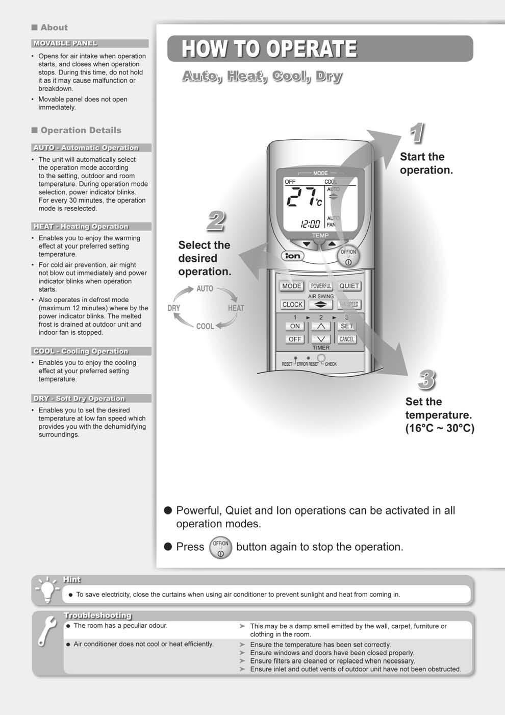
20 9 Operation Details 9.1. BASIC FUNCTION Inverter control, which equipped with a microcomputer in determining the most suitable operating mode as time passes, automatically adjusts output power for maximum comfort always. In order to achieve the suitable operating mode, the microcomputer maintains the set temperature by measuring the temperature of the environment and performing temperature shifting. The compressor at outdoor unit is operating following the frequency instructed by the microcomputer at indoor unit that judging the condition according to internal setting temperature and intake air temperature Internal Setting Temperature Once the operation starts, remote control setting temperature will be taken as base value for temperature shifting processes. These shifting processes are depending on the air conditioner settings and the operation environment. The final shifted value will be used as internal setting temperature and it is updated continuously whenever the electrical power is supplied to the unit. Table (a): Auto Operation Mode Setting Mode Shift: Temperature Shift ( C) Cooling/Soft Dry Heating -2.0 Heating Cooling/Soft Dry
21 Table (b): Outdoor Air Temperature Shifting Mode: Outdoor Temperature, X ( C): Temperature Shift ( C) TE9DKE TE12DKE Cooling/Soft Dry 38 X X X X Heating 21 X X X X X X Table (c): Fan Speed Shifting Mode: Fan Speed: Temperature Shift ( C) Cooling All Soft Dry All +1.0 Heating Lo +1.0 Hi, Me-, Me, Me+, Auto (TE9DKE), (TE12DKE) Table (d): Start-Up Shifting Mode within 60 Minutes from Start-up: Temperature Shift ( C) Cooling/Soft Dry -1.0 Heating Indoor Power Relay Control The Power Relay turns on under the following conditions. 1. For three minutes, when plugged in the A/C or the Error Reset button on remote controller is pressed. 2. During Installation Check Mode and following for three minutes after checking. 3. During On-timer sampling and during Preliminary operation. 4. During Operation and following for three minutes after the operation is stopped. 5. During Auto Operation, Test run, Forced Heating or Odour Removal Operation and following for three minutes after the operation is stopped Room Air Temperature Control (Compressor Control) Operating frequency of a compressor is decided according to temperature differences between remote controller setting and room temperatures. A relative method which gives frequency changes, based on the decided frequency, will provide you with comfortable room environment that is not affected by operating conditions Cooling Operation Thermostat Control [Intake Air Temp. - Remote Controller Setting Temp.] > [Thermostat-OFF Temp C] Operated in corresponding frequency. Frequency is decided after a completion of the starting control (in 60 seconds). When Room Temp. is below [Thermostat-OFF Temp.] continuously for 3 minutes or more, it turns to Thermostat- OFF operation. Cooling Power TE9DKE TE12DKE Intake Air Temp. Maximum 2.7kW 4.0kW Difference ( C) Rated 2.5kW 3.6kW Intermediate ~ ~ Minimum 0.8kW 0.8kW (-1.00) OFF
22 Dry Operation Thermostat Control [Intake Air Temp. - Remote Controller Setting Temp.] > [Thermostat-OFF Temp C] Operated in corresponding frequency. Frequency is decided after a completion of the starting control (in 60 seconds). When Room Temp. is below [Thermostat-OFF Temp.] continuously for 3 minutes or more, it turns to Thermostat- OFF operation. When room temperature almost comes to Thermostat-OFF Temp., the operation turns to the Minimum power & fan speed: SSLo. Dry Power TE9DKE TE12DKE Intake Air Temp. Maximum 2.7kW 4.0kW Difference ( C) Rated 2.5kW 3.6kW Intermediate ~ ~ Minimum 0.8kW 0.8kW (-2.50) OFF Heating Operation Thermostat Control [Intake Air Temp. - Remote Controller Setting Temp.] > [Thermostat-OFF Temp C] Operated in corresponding frequency. Frequency is decided after a completion of starting control (in 60 seconds). When Room Temp. is below Thermostat-OFF Temp. continuously for 3 minutes or more, it turns to Thermostat- OFF operation. When room temperature almost comes to Thermostat-OFF Temp., the operation turns to the Maximum power. Heating Power TE9DKE TE12DKE Intake Air Temp. OFF Difference ( C) Minimum 0.8kW 0.8kW Intermediate ~ ~ Rated 3.5kW 4.5kW (+1.00) Maximum 4.6kW 6.2kW 22
23 9.4. Airflow Direction Control Vertical louver is controlled with Vertical Airflow Direction button on remote controller and by operation conditions, as shown in the table below Vertical Airflow Louver Angle Cooling and Dry Operations Airflow Direction Auto Airflow Direction Setting Manual Operation Vertical Auto Operation Powerful-ON It swings when airflow direction is set with remote controller. It does not swing while indoor fan is stopped. (It is fixed at the upper limit.). The louver is fixed at five-level setting position when the airflow direction is set with remote controller. Heating Operation Airflow Direction Auto Airflow Direction Setting Fixed by Heat Exchanger Temperature Powerful Operation Remote Control When Heat Exchanger Temperature is less than 33 C When Heat Exchanger Temperature is less than 33 C When Heat Exchanger Temperature is between 33 C (, incl.) and 127 C When Heat Exchanger Temperature is between 33 C (, incl.) and 127 C The louver is fixed at five-level setting position when the airflow direction is set with remote controller. Odour Removal Control Airflow Direction Auto Airflow Direction Setting The vertical louver is fully opened and move to the setting position when the unit is turned on with the remote controller. The vertical louver remains open position when the unit is turned off during operation. The horizontal louver is manually operated. 23
24 9.5. Quiet operation (Cooling Mode / Cooling area of Dry Mode) A. Purpose To provide quiet cooling operation compare to normal operation. B. Control condition a. Quiet operation start condition When quiet button at remote control is pressed. Quiet LED illuminates. b. Quiet operation stop condition 1. When one of the following conditions is satisfied, quiet operation stops: a. Powerful button is pressed. b. Stop by OFF/ON switch. c. Timer off activates. d. When change mode to ION only mode. 2. When quiet operation is stopped, operation is shifted to normal operation with previous setting. 3. When fan speed is changed, quiet operation is shifted to quiet operation of the new fan speed. 4. When operation mode is changed, quiet operation is shifted to quiet operation of the new mode, except ION only mode. 5. During quiet operation, if timer on activates, quiet operation maintains. 6. After off, when on back, quiet operation is not memorised. C. Control contents 1. Fan speed is changed from normal setting to quiet setting of respective fan speed. This is to reduce sound of Hi, Me, Lo for 3dB. 2. Fan speed for quiet operation is -100 rpm from setting fan speed Quiet operation under Soft Dry operation (Dry area at Dry Mode) Automatic Fan Speed (Dry operation) Manual Fan Speed (Dry operation) 24
25 Quiet operation (Heating) A. Purpose To provide quiet heating operation compare to normal operation. B. Control condition a. Quiet operation start condition When quiet button at remote control is pressed. Quiet LED illuminates. b. Quiet operation stop condition 1. When one of the following conditions is satisfied, quiet operation stops: a. Powerful button is pressed. b. Stop by OFF/ON switch. c. Timer off activates. d. When change mode to ION only mode. 2. When quiet operation is stopped, operation is shifted to normal operation with previous setting. 3. When fan speed is changed, quiet operation is shifted to quiet operation of the new fan speed. 4. When operation mode is changed, quiet operation is shifted to quiet operation of the new mode, except ION only mode. 5. During quiet operation, if timer on activates, quiet operation maintains. 6. After off, when on back, quiet operation is not memorised. C. Control contents a. Fan Speed manual 1. Fan speed is changed from normal setting to quiet setting of respective fan speed. This is to reduce sound of Hi, Me, Lo for 3dB. 2. Fan speed for quiet operation is -100 rpm from setting fan speed. 3. Fan Speed Auto If FM Lo -100 rpm reduce from normal Heating Auto Fan Speed If FM Lo maintain RPM Indoor FM RPM depends on Piping temp sensor of indoor heat exchanger. 25

26 9.6. Indoor Fan Control Fan Motor Control Fan speed is controlled according to operation conditions such as fan speed setting on the remote controller as shown in the table below. There is a different speed control from setting on the remote controller. When Dry operation is selected, in the Cooling area, fan speed will be switched to one at Cooling mode and in the Dry area, it will be switched to one at Dry mode. Indoor fan operates in Quiet and Quiet Control indicated in the table below by pressing the QUIET button on the remote controller. CS-TE9DKE Cooling and Dry Operations Heating Operation 26

27 CS-TE12DKE Cooling and Dry Operations Heating Operation 27
28 Cooling Operation 1. Automatic Fan Speed Odour Cut Control is equipped with this model. Fan is temporarily stopped for 40 seconds at the beginning of unit operation or Thermostat-ON in order to wash away odour ingredients from heat exchanger with dehumidifying water. Conditions of Control Starting When Cooling fan speed is Auto, When conditions other than Defrost control, When indoor Pipe temperature is in the area shown in the figure below, When operations other than Powerful operation, Items to be controlled According to Intake air - Setting temperature differences, indoor fan speed is adjusted by revolution speed correction of automatic normal fan speed as shown in the graph below. In addition, fan speed will be reduced to MIN rpm under the following conditions: Neural control stability [Intake air temp. - Indoor Pipe Temp.] < 13 C Operating frequency < 25 Hz 28
29 2. Maximum Cooling Power When cooling load is big, if fan speed: SHi and temp: 16 C are set, fan speed will be increased for 30 minutes after operation starts in order to decrease room temperature quickly. (Refer to Indoor fan speed control for each model.) 3. Dew Condensation Prevention Control Fan speed will be reduced if Dew Condensation Prevent Control is operated. 4. Forced Cooling Operation Fan speed at Forced Cooling operation with the Emergency Operation button is Hi. (Refer to "Indoor fan speed control" for each model.) 5. Emergency Operation Fan speed when operation with the Emergency Operation button or Cooling operation with remote controller during performance of breakdown diagnosis (breakdown that emergency operation is possible) is Me+. (Refer to "Indoor fan speed control" for each model.) Dry Operation 1. Basic Fan Speed In the cooling mode area, fan operates in the same speed as cooling operation mode. In the dry mode area, it is switched to "SLo". (Refer to "Indoor fan speed control" for each model.) In the Thermostat-OFF mode, fan stops for 5.5 minutes and after that, operates at a speed of level Automatic Fan Speed Odour Cut Control functions and fan operates repeatedly between the 60-second stop and the 30-second SLo operations. In the beginning of unit operation and Thermostat-ON, fan stops for 40 seconds Heating Operation 1. Hot Start & Cold Draft When Indoor Exchanger Temperature is low at the beginning of the operation, fan is stopped. Cold Draft is prevented by increased Exchanger temperature in proportion to fan speed. 2. Auto Fan Speed In Auto Fan Speed, fan speed is controlled according to Exchanger temperature. (Refer to "Indoor fan speed control" for each model.) 3. Forced Heating Operation Fan speed at Forced Heating operation with the Emergency Operation button is "Hi". (Refer to "Indoor fan speed control" for each model.) 4. Fan speed when operation with the Emergency Operation button or Heating operation with remote controller during performance of breakdown diagnosis (breakdown that emergency operation is possible) is " Me+". (Refer to "Indoor fan speed control" for each model.) 9.7. Powerful Operation If the POWERFUL button is pressed during operating in Cooling, Heating, Dry or AUTO, unit always forces to operate respectively in Quick Cooling, Dry and Quick Heating for 5 minutes, which fan speed is "SHi" even though unit is in each stable area Cooling Operation Airflow direction, Fan speed and Setting temperature are optimized. Intake Air temperature - Remote controller setting temperature is detected every 20 seconds by indication from indoor unit and controlled to each area. Quick Cooling Unit forcibly turns to Quick Cooling operation for 5 minutes after POWERFUL ON even through it is in the stable area. If unit gets out of the Quick Cooling area, it turns to Chilly Cooling operation. Chilly Cooling Discharge Air temperature is kept low by changing fan speed according to room temperature and chilly feeling is produced. 29

30 Dry Operation Airflow direction, Fan speed and Setting temperature are optimized. Intake Air temperature - Remote controller setting temperature is detected every 20 seconds by indication from indoor unit and controlled to each area. Quick Dry Unit forcibly turns to Quick Dry operation for 5 minutes after POWERFUL ON even through it is in the stable area. If unit gets out of the area, it turns to Chilly Dry operation. Chilly Dry Discharge Air temperature is kept low by changing fan speed according to room temperature and chilly feeling is produced Heating Operation Airflow direction, Fan speed and Setting temperature are optimized. Intake Air temperature - Remote controller setting temperature is detected every 20 seconds by indication from indoor unit and controlled to each area. Quick Heating Unit forcibly turns to Quick Heating operation for 5 minutes after POWERFUL ON even through it is in the stable area. If unit gets out of the area, it turns to Warm Heating operation. Warm Heating Discharge Air temperature is kept high by changing fan speed according to room temperature and warm feeling is produced Automatic Operation Operation mode (Cooling, Dry and Heating) is automatically selected. Operation mode is selected at the beginning of unit operation and every 30 minutes. Temperature, Fan speed and Airflow directions are set with remote controller Operation Mode Selection Operation mode is selected according to outdoor temperature, intake air temperature and setting temperature. 1. "Heating" is selected when intake air temperature is below 16 C. 2. "Cooling" is selected when intake air temperature is 25 C or more. (But, when intake air temperature is 16 C or more.) 3. Selectable range of "Heating" and "Cooling" for setting temperature on the remote controller is increased when outside air temperature is below 25 C Setting Temperature Shift in Automatic Operation When Cooling mode is selected, setting temperature is shifted to +1 C. When Heating mode is selected, setting temperature is shifted to -1 C. 30

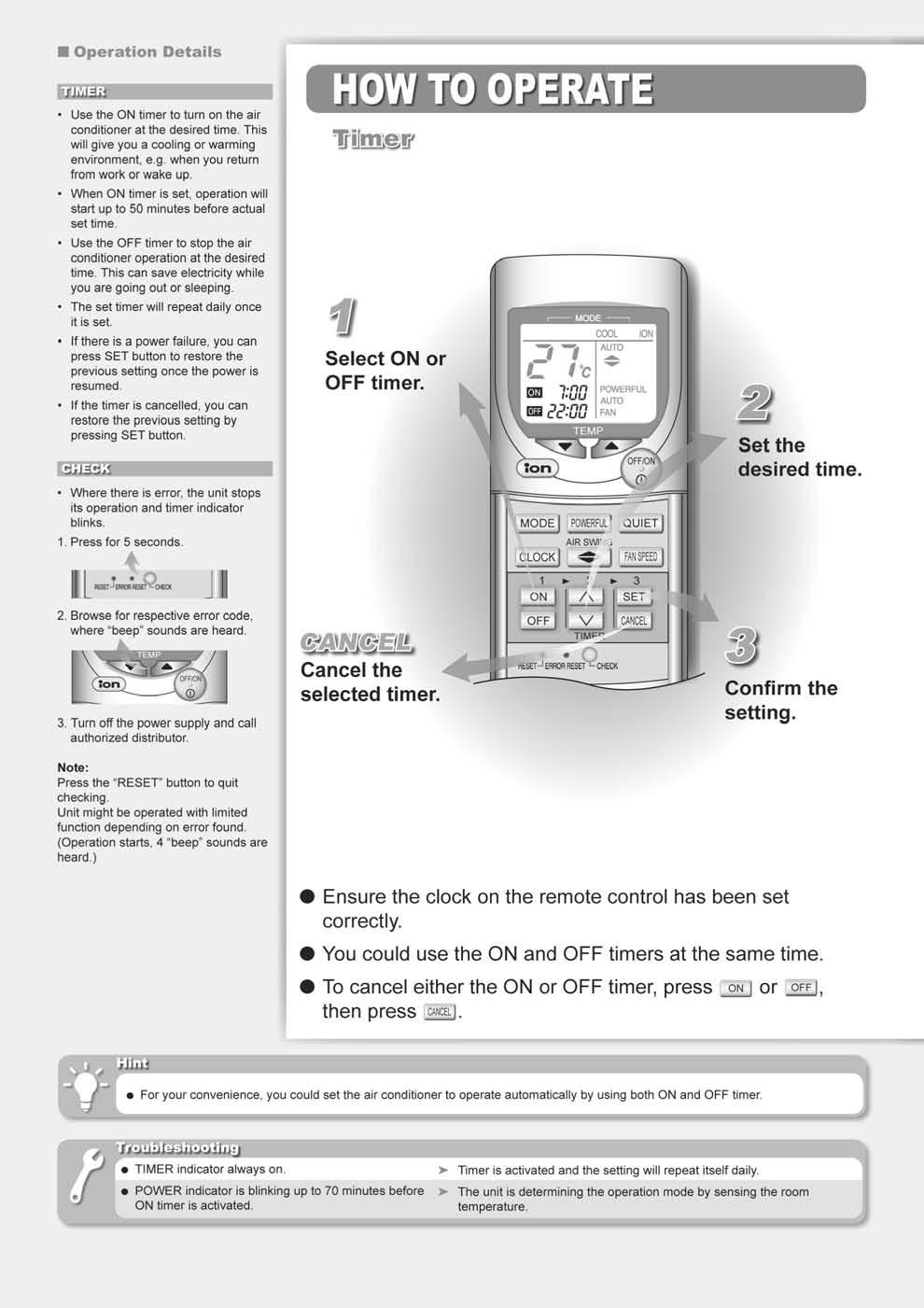
31 9.9. Timer Operation (24H Real Timer) On-timer and OFF-timer can be set simultaneously. Both On-timer and OFF-timer functions operate until they are canceled. (Excluding when power supplying condition is bad.) An example of ON-timer operation An example of OFF-timer operation Preliminary operation Unit operates preliminarily until room temperature reaches setting temperature on ON-timer setting time. Preliminary operation times are as shown in the table below. Indoor and outdoor fans operate for 30 seconds in 70 minutes before setting time and sampling of outdoor air and intake air temperatures is performed. Fan speed and airflow directions in preliminary operation are based on remote controller setting. (Same condition as in normal operation.) In preliminary operation, deicing judgment is performed after heating operated for 15 minutes in 50 minutes before setting ON-time. This is because it makes startup time short when outdoor air temperature is extremely low in midwinter. Deicing Judgment: Deicing operation (Max. 12 minutes) will be performed when outdoor air temperature is below 0 C, if outdoor heat exchanger temperature of below 0 C continues for 14 minutes and below -8 C continues for 10 minutes or more. Preliminary operation in Cooling or Dry mode Outdoor Air Intake Air Warming-up Operation Temperature Temperature Starting Time 35 C or more Before 15 min. 30 C or more Before 15 min C C Before 10 min. Below 30 C Below 25 C Before 5 min. Preliminary operation in Heating mode Outdoor Air Intake Air Warming-up Operation Temperature Temperature Starting Time 5 C or more Before 40 min. 15 C or more Before 40 min. 0-5 C 5-15 C Before 45 min. Below 0 C Below 5 C Before 50 min Auto Restart Control 1. When the power supply is cut off during the operation of air conditioner, the compressor will re-operate within three to four minutes (there are 10 patterns between 2 minutes 58 seconds and 3 minutes 52 seconds to be selected randomly) after power supply resumes. 2. This type of control is not applicable during ON/OFF Timer setting. 31
32 9.11. Ionizer Operation Negative Ion Generator Display and operation for the Negative Ion Generator remain unchanged for ION only operation and simultaneous ION operation. Refer to the ION operation described below. Single blinking of the ION LED does not indicate Breakdown. When unit was operated under the condition that a discharge insulation of the Ion Cleaning equipment is deteriorated (Dust, Attached water, etc.): 1. If the insulation deterioration of the unit discharge part is small; When air cleaning abnormal status is detected in 1 minute or more from the unit starts operating, the unit is OFF for 10 minutes. (The ION LED and CLEAN monitor light up.) The unit is ON in 5 minutes. (Repeating) 2. If the insulation deterioration of the unit discharge part is big; When air cleaning abnormal status is detected within 1 minute from the unit starts operating, the unit is shut OFF immediately and the ION LED blinks. 3. If the insulation of the Ionizer is deteriorated; When abnormal status is detected, the unit is OFF for 30 minutes. When abnormal status is detected 25 times, the operation stops and the ION LED blinks. (It will be reset if normal status continues for 10 minutes before reaching 25 times.) To cancel it, stop the operation while the ION LED is blinking. Note: Set ION Air Cleaning operation again because it is canceled when re-operated. 32
33 9.12. Protection Control Time Delay Safety Control 1. The compressor will not start for two minutes after stop of operation. 2. This control is not applicable if the power supply is cut off and on again or after 4-way valve deices condition Seconds Forced Operation 1. Once the compressor starts operation, it will not stop its operation for 30 minutes. 2. However, it can be stopped by using remote control or Auto Switch at indoor unit. * The other Protection controls are shown in Protection Control from Overload Cooling & Dry Operation and Protection Control from Overload Heating Operation. 33

34 10 Operating Instructions 34

35 35 CS-TE9DKE CU-TE9DKE / CS-TE12DKE CU-TE12DKE
36 36

37 37 CS-TE9DKE CU-TE9DKE / CS-TE12DKE CU-TE12DKE
38 38

39 39 CS-TE9DKE CU-TE9DKE / CS-TE12DKE CU-TE12DKE
40 11 Installation Instructions Required tools for Installation Works 1. Philips screw driver 5. Spanner 9. Gas leak detector 13. Multimeter 2. Level gauge 6. Pipe cutter 10. Measuring tape 14. Torque wrench 18 N.m (1.8 kgf.m) 42 N.m (4.2 kgf.m) 55 N.m (5.5 kgf.m) 3. Electric drill, hole core drill 7. Reamer 11. Thermometer 15. Vacuum pump (ø70 mm) 4. Hexagonal wrench (4 mm) 8. Knife 12. Megameter 16. Gauge manifold SAFETY PRECAUTIONS Read the following SAFETY PRECAUTIONS carefully before installation. Electrical work must be installed by a licensed electrician. Be sure to use the correct rating of the power plug and main circuit for the model to be installed. The caution items stated here must be followed because these important contents are related to safety. The meaning of each indication used is as below. Incorrect installation due to ignoring of the instruction will cause harm or damage, and the seriousness is classified by the following indications. This indication shows the possibility of causing death or serious injury. This indication shows the possibility of causing injury or damage to properties only. The items to be followed are classified by the symbols: Symbol with background white denotes item that is PROHIBITED from doing. Carry out test running to confirm that no abnormality occurs after the installation. Then, explain to user the operation, care and maintenance as stated in instructions. Please remind the customer to keep the operating instructions for future reference. 1. Engage dealer or specialist for installation. If installation done by the user is defective, it will cause water leakage, electrical shock or fire. 2. Install according to this installation instruction strictly. If installation is defective, it will cause water leakage, electrical shock or fire. 3. Use the attached accessories parts and specified parts for installation. Otherwise, it will cause the set to fall, water leakage, fire or electrical shock. 4. Install at a strong and firm location which is able to withstand the set s weight. If the strength is not enough or installation is not properly done, the set will drop and cause injury. 5. For electrical work, follow the local national wiring standard, regulation and this installation instruction. An independent circuit and single outlet must be used. If electrical circuit capacity is not enough or defect found in electrical work, it will cause electrical shock or fire. 6. Use the specified cable (1.5 mm 2 ) and connect tightly for indoor/outdoor connection. Connect tightly and clamp the cable so that no external force will be acted on the terminal. If connection or fixing is not perfect, it will cause heat-up or fire at the connection. 7. Wire routing must be properly arranged so that control board cover is fixed properly. If control board cover is not fixed perfectly, it will cause heat-up at connection point of terminal, fire or electrical shock. 8. When carrying out piping connection, take care not to let air substances other than the specified refrigerant go into refrigeration cycle. Otherwise, it will cause lower capacity, abnormal high pressure in the refrigeration cycle, explosion and injury. 9. Do not damage or use unspecified power supply cord. Otherwise, it will cause fire or electrical shock. 10. Do not modify the length of the power supply cord or use of the extension cord, and do not share the single outlet with other electrical appliances. Otherwise, it will cause fire or electrical shock. 40
41 1. The equipment must be earthed and installed with earth leakage breaker. It may cause electrical shock if grounding is not perfect. 2. Do not install the unit at place where leakage of flammable gas may occur. In case gas leaks and accumulates at surrounding of the unit, it may cause fire. 3. Carry out drainage piping as mentioned in installation instructions. If drainage is not perfect, water may enter the room and damage the furniture. 1. Selection of the installation location. Select an installation location which is rigid and strong enough to support or hold the unit, and select a location for easy maintenance. 2. Power supply connection to the room air conditioner. Connect the power supply cord of the room air conditioner to the mains using one of the following method. Power supply point shall be the place where there is ease for access for the power disconnection in case of emergency. In some countries, permanent connection of this room air conditioner to the power supply is prohibited. 1. Power supply connection to the receptacle using a power plug. Use an approved 15A/16A power plug with earth pin for the connection to the socket. 2. Power supply connection to a circuit breaker for the permanent connection. Use an approved 15A circuit breaker for the permanent connection. It must be a double pole switch with a minimum 3 mm contact gap. 3. Do not release refrigerant. Do not release refrigerant during piping work for installation, reinstallation and during repairing a refrigeration parts. Take care of the liquid refrigerant, it may cause frostbite. 4. Installation work. It may need two people to carry out the installation work. 5. Do not install this appliance in a laundry room or other location where water may drip from the ceiling, etc. 41


42 Attached accessories Indoor/Outdoor Unit Installation Diagram Applicable piping kit CZ-3F5, 7BP (CS-TE9DKE) CZ-4F5, 7, 10BP (CS-TE12DKE) INDOOR UNIT SELECT THE BEST LOCATION There should not be any heat source or steam near the unit. There should not be any obstacles blocking the air circulation. A place where air circulation in the room is good. A place where drainage can be easily done. A place where noise prevention is taken into consideration. Do not install the unit near the door way. Ensure the spaces indicated by arrows from the wall, ceiling, fence or other obstacles. Recommended installation height for indoor unit shall be at least 2.5 m. OUTDOOR UNIT If an awning is built over the unit to prevent direct sunlight or rain, be careful that heat radiation from the condenser is not obstructed. There should not be any animal or plant which could be affected by hot air discharged. Keep the spaces indicated by arrows from wall, ceiling, fence or other obstacles. Do not place any obstacles which may cause a short circuit of the discharged air. If piping length is over the common length, additional refrigerant should be added as shown in the table. This illustration is for explanation purposes only. The indoor unit will actually face a different way. 42

43 11.2. INDOOR UNIT SELECT THE BEST LOCATION (Refer to Select the best location section) TO DRILL A HOLE IN THE WALL AND INSTALL A SLEEVE OF PIPING HOW TO FIX INSTALLATION PLATE The mounting wall is strong and solid enough to prevent it from the vibration. 1. Insert the piping sleeve to the hole. 2. Fix the bushing to the sleeve. 3. Cut the sleeve until it extrudes about 15 mm from the wall. Caution When the wall is hollow, please be sure to use the sleeve for tube ass y to prevent dangers caused by mice biting the connecting cable. 4. Finish by sealing the sleeve with putty or caulking compound at the final stage. The centre of installation plate should be at more than 450 mm at right of the wall. The centre of installation plate should be at more than 450 mm at left of the wall. The distance from installation plate edge to ceiling should more than 66 mm. From installation plate left edge to unit s left side is 20 mm. From installation plate right edge to unit s right is 70 mm. : For left side piping, piping connection for liquid should be this line. : For left side piping, piping connection for gas should be about 50 mm from this line. : For left side piping, piping connecting cable should be about 750 mm from this line. 1. Mount the installation plate on the wall with 5 screws or more. (If mounting the unit on the concrete wall, consider using anchor bolts.) Always mount the installation plate horizontally by aligning the marking-off line with the thread and using a level gauge INDOOR UNIT INSTALLATION 1. For the right rear piping 2. For the right and right bottom piping 2. Drill the piping plate hole with ø70 mm hole-core drill. The centre of the right piping hole is at the intersection of lines extending vertically from the edge of the installation plate and horizontally from the sideways arrow on the installation plate. (see figure above.) The centre of the left piping hole is at the intersection of lines extending vertically from the downward arrow on the installation plate and horizontally from the sideways arrow on the installation plate. (see figure above.) Drill the piping hole at either the right or the left and the hole should be slightly slanted to the outdoor side. 43


44 3. For the embedded piping (This can be used for left rear piping & left bottom piping also.) 44
 or heavier cord.")


45 CONNECT THE CABLE TO THE INDOOR UNIT 1. The inside and outside connecting cable can be connected without removing the front grille. 2. Connecting cable between indoor unit and outdoor unit shall be approved polychloroprene sheathed mm 2 flexible cord, type designation 245 IEC 57 (H05RN-F) or heavier cord. Ensure the color of wires of outdoor unit and the terminal Nos. are the same to the indoor s respectively. Earth lead wire shall be longer than the other lead wires as shown in the figure for the electrical safety in case of the slipping out of the cord from the anchorage. HOW TO TAKE OUT FRONT GRILLE Please follow the steps below to take out front grille if necessary such as when servicing. 1. Set the vertical airflow direction louver to the horizontal position. 2. Slide down the two caps on the front grille as shown in the illustration below, and then remove the two mounting screws. 3. Pull the lower section of the front grille towards you to remove the front grille. Caution When reinstalling the front grille, first set the vertical airflow direction louver to the horizontal position and then carry out above steps 2-3 in the reverse order. Secure the cable onto the control board with the holder (clamper). AUTO SWITCH OPERATION INSTALLATION OF SUPER ALLERU-BUSTER FILTER 1. Open the front panel. 2. Remove the air filters. 3. Put Super Alleru-buster filter into place as shown in illustration below. The below operations will be performed by pressing the AUTO switch. 1. AUTO OPERATION MODE The Auto operation will be activated immediately once the Auto Switch is pressed. 2. TEST RUN OPERATION (FOR PUMP DOWN/SERVICING PURPOSE) The Test Run operation will be activated if the Auto Switch is pressed continuously for more than 5 sec. to below 8 sec. A pep sound will occur at the fifth sec., in order to identify the starting of Test Run operation. 45

46 11.3. OUTDOOR UNIT SELECT THE BEST LOCATION (Refer to Select the best location section) INSTALL THE OUTDOOR UNIT After selecting the best location, start installation according to Indoor/Outdoor Unit Installation Diagram. 1. Fix the unit on concrete or rigid frame firmly and horizontally by bolt nut. (ø10 mm). 2. When installing at roof, please consider strong wind and earthquake. Please fasten the installation stand firmly with bolt or nails CONNECTING THE PIPING Connecting The Piping To Indoor Unit Please make flare after inserting flare nut (locate at joint portion of tube assembly) onto the copper pipe. (In case of using long piping) Connect the piping Align the center of piping and sufficiently tighten the flare nut with fingers. Further tighten the flare nut with torque wrench in specified torque as stated in the table. MODEL Piping size (Torque) Gas Liquid TE9CK 3/8 (42 N.m) 1/4 (18 N.m) TE12CK 1/2 (55 N.m) 1/4 (18 N.m) Connecting The Piping To Outdoor Unit Decide piping length and then cut by using pipe cutter. Remove burrs from cut edge. Make flare after inserting the flare nut (located at valve) onto the copper pipe. Align center of piping to valves and then tighten with torque wrench to the specified torque as stated in the table. Cutting And Flaring The Piping 1. Please cut using pipe cutter and then remove the burrs. 2. Remove the burrs by using reamer. If burrs is not removed, gas leakage may be caused. Turn the piping end down to avoid the metal powder entering the pipe. 3. Please make flare after inserting the flare nut onto the copper pipes. 46
47 EVACUATION OF THE EQUIPMENT (FOR EUROPE & OCEANIA DESTINATION) WHEN INSTALLING AN AIR CONDITIONAL, BE SURE TO EVACUTE THE AIR INSIDE THE INDOOR UNIT AND PIPES in the following procedure. 1. Connect a charging hose with a push pin to the Low and High side of a charging set and the service port of the 3-way valve. Be sure to connect the end of the charging hose with the push pin to the service port. 2. Connect the center hose of the charging set to a vacuum pump with check valve, or vacuum pump and vacuum pump adaptor. 3. Turn on the power switch of the vacuum pump and make sure that the needle in the gauge moves form 0 cmhg (0 MPa) to - 76cm Hg (-0.1 MPa). Then evacuate the air approximately 15 minutes. 4. Close the Low and High side valve of the charging set the turn off the vacuum pump. Make sure that the needle in the gauge does not move after approximately 5 minutes. Note: BE SURE TO FOLLOW THIS PROCEDURE INORDER IN ORDER TO AVOID REFRIGERANT GAS LEAKAGE. 5. Disconnect the charging hose from vacuum pump and from the service port of the 3-way valve. 6. Tighten the service port caps of the 3-way valve at a torque of 18 N.m with a torque wrench. 7. Remove the valve caps of both of the 2-way valve and 3-way valve. Position both of the valves to OPEN using a hexagonal wrench (4 mm). 8. Mount valve caps onto the 2-way valve and the 3-way valve. Be sure to check for gas leakage. Caution If gauge needle does not move from 0 cmhg (0 MPa) to -76 cmhg (-0.1 MPa), in step 3 above take the following measure: If the leag stops when the piping connections are tightened further, continue working form step 3. If the leak does not stop when the connections are retightened, repair the location of leak. Do not release refrigerant during piping work for installation and reinstallation. Take care of the liquid refrigerant, it may cause frostbite. 47
 or heavier cord.")

. 4. Attach the control board cover back in its original position with the screw. 11.3.6. PIPE INSULATION 1.")
48 CONNECT THE CABLE TO THE OUTDOOR UNIT 1. Remove the control board cover from the unit by loosening the screw. 2. Connecting cable between indoor unit and outdoor unit shall be approved polychloroprene sheathed mm 2 flexible cord, type designation 245 IEC 57 (H05RN-F) or heavier cord. CHECK THE DRAINAGE Open front panel and remove air filters. (Drainage checking can be carried out without removing the front grille.) Pour a glass of water into the drain tray-styrofoam. Ensure that water flows out from drain hose of the indoor unit. EVALUATION OF THE PERFORMANCE Operate the unit at cooling operation mode for fifteen minutes or more. Measure the temperature of the intake and discharge air. Ensure the difference between the intake temperature and the discharge is more than 8 C. 3. Secure the cable onto the control board with the holder (clamper). 4. Attach the control board cover back in its original position with the screw PIPE INSULATION 1. Please carry out insulation at pipe connection portion as mentioned in Indoor/Outdoor Unit Installation Diagram. Please wrap the insulated piping end to prevent water from going inside the piping. 2. If drain hose or connecting piping is in the room (where dew may form), please increase the insulation by using POLY-E FOAM with thickness 6 mm or above. DISPOSAL OF OUTDOOR UNIT DRAIN WATER If a drain elbow is used, the unit should be placed on a stand which is taller than 3 cm. If the unit is used in an area where temperature falls below 0 C for 2 or 3 days in succession, it is recommended not to use a drain elbow, for the drain water freezes and the fan will not rotate. CHECK ITEMS Is there any gas leakage at flare nut connection? Has the heat insulation been carried out at flare nut connection? Is the connecting cable being fixed to terminal board firmly? Is the connecting cable being clamped firmly? Is the drainage OK? (Refer to Check the drainage section) Is the earth wire connection properly done? Is the indoor unit properly hooked to the installation plate? Is the power supply voltage complied with rated value? Is there any abnormal sound? Is the cooling operation normal? Is the thermostat operation normal? Is the remote control s LCD operation normal? Is the air purifying filter installed? 48
49 12 Installation and Servicing Air Conditioner Using R410A OUTLINE About R410A Refrigerant 1. Converting air conditioners to R410A Since it was declared in1974 that chlorofluorocarbons (CFC), hydro chlorofluorocarbons (HCFC) and other substances pose a destructive danger to the ozone layer in the earth s upper stratosphere (20 to 40 km above the earth), measures have been taken around the world to prevent this destruction. The R22 refrigerant which has conventionally been used in ACs is an HCFC refrigerant and, therefore, possesses this ozonedestroying potential. International regulations (the Montreal Protocol on Ozone-Damaging Substances) and the domestic laws of various countries call for the early substitution of R22 by a refrigerant which will not harm the ozone layer. In ACs, the HFC refrigerant which has become the mainstream alternative is called R410A. Compared with R22, the pressure of R410A is approximately 1.6 times as high at the same refrigerant temperature, but the energy efficiency is about the same. Consisting of hydrogen (H), fluorine (F) and carbon (C), R410A is an HFC refrigerant. Another typical HFC refrigerant is R407C. While the energy efficiency of R407C is somewhat inferior to that of R410A, it offers the advantage of having pressure characteristics which are about the same as those of R22, and is used mainly in packaged ACs. 2. The characteristics of HFC (R410A) refrigerants a. Chemical characteristics The chemical characteristics of R410A are similar to those of R22 in that both are chemically stable, non-flammable refrigerants with low toxicity. However, just like R22, the specific gravity of R410A gas is heavier than that of air. Because of this, it can cause an oxygen deficiency if it leaks into a closed room since it collects in the lower area of the room. It also generates toxic gas when it is directly exposed to a flame, so it must be used in a well ventilated environment where it will not collect. Table 1 Physical comparison of R410A and R22 R410A R22 Composition (wt%) R32/R125 (50/50) R22 (100) Boiling point ( C) Vaporizing pressure (25 C) 1.56 Mpa (15.9 kgf/cm 2 ) 0.94 Mpa (9.6 kgf/cm 2 ) Saturated vapor density 64.0 kg/m kg/m 3 Flammability Non-flammable Non-flammable Ozone-destroying point (ODP) Global-warming point (GWP) b. Compositional change (pseudo-azeotropic characteristics) R410A is a pseudo-azeotropic mixture comprising the two components R32 and R125. Multi-component refrigerants with these chemical characteristics exhibit little compositional change even from phase changes due to vaporization (or condensation), which means that there is little change in the circulating refrigerant composition even when the refrigerant leaks from the gaseous section of the piping. Accordingly, R410A can be handled in almost the same manner as the single-component refrigerant R22. However, when charging, because there is a slight change in composition between the gas phase and the liquid phase inside a cylinder or other container, charging should basically begin with the liquid side. c. Pressure characteristics As seen in Table 2, the gas pressure of R410A is approximately 1.6 times as high as that of R22 at the same refrigerant temperature, which means that special R410A tools and materials with high-pressure specifications must be used for all refrigerant piping work and servicing. Table 2 Comparison of R410A and R22 saturated vapor density Unit: MPa Refrigerant Temperature ( C) R410A R
50 d. R410A refrigerating machine oil Conventionally, mineral oil or a synthetic oil such as alkylbenzene has been used for R22 refrigerating machine oil. Because of the poor compatibility between R410A and conventional oils like mineral oil, however, there is a tendency for the refrigerating machine oil to collect in the refrigerating cycle. For this reason, polyester and other synthetic oils which have a high compatibility with R410A are used as refrigerating machine oil. Because of the high hygroscopic property of synthetic oil, more care must be taken in its handling than was necessary with conventional refrigerating machine oils. Also, these synthetic oils will degrade if mixed with mineral oil or alkylbenzene, causing clogging in capillary tubes or compressor malfunction. Do not mix them under any circumstances Safety Measures When Installing/Servicing Refrigerant Piping Cause the gas pressure of R410A is approximately 1.6 times as high as that of R22, a mistake in installation or servicing could result in a major accident. It is essential that you use R410A tools and materials, and that you observe the following precautions to ensure safety. 1. Do not use any refrigerant other than R410A in ACs that have been used with R410A. 2. If any refrigerant gas leaks while you are working, ventilate the room. Toxic gas may be generated if refrigerant gas is exposed to a direct flame. 3. When installing or transferring an AC, do not allow any air or substance other than R410A to mix into the refrigeration cycle. If it does, the pressure in the refrigeration cycle can become abnormally high, possibly causing an explosion and/or injury. 4. After finishing the installation, check to make sure there is no refrigerant gas leaking. 5. When installing or transferring an AC, follow the instructions in the installation instructions carefully. Incorrect installation can result in an abnormal refrigeration cycle or water leakage, electric shock, fire, etc. 6. Do not perform any alterations on the AC unit under any circumstances. Have all repair work done by a specialist. Incorrect repairs can result in a water leakage, electric shock, fire, etc TOOLS FOR INSTALLING/SERVICING REFRIGERANT PIPING Necessary Tools In order to prevent an R410A AC from mistakenly being charged with any other refrigerant, the diameter of the 3-way valve service port on the outdoor unit has been changed. Also, to increase its ability to withstand pressure, the opposing dimensions have been changed for the refrigerant pipe flaring size and flare nut. Accordingly, when installing or servicing refrigerant piping, you must have both the R410A and ordinary tools listed below. Table 3 Tools for installation, transferring or replacement Type of work Ordinary tools R410A tools Flaring Flaring tool (clutch type), pipe cutter, reamer Copper pipe gauge for clearance Adjustment, flaring tool (clutch type)*1) Bending, connecting pipes Torque wrench (nominal diameter 1/4, 3/8,1/2). Fixed spanner (opposing sides 12 mm, 17 mm, 19 mm). Adjustable wrench, Spring bender Air purging Vacuum pump. Hexagonal wrench (opposing sides 4 mm) Manifold gauge, charging hose, vacuum pump adaptor Gas leak inspection Gas leak inspection fluid or soapy water Electric gas leak detector for HFC refrigerant*2) *1) You can use the conventional (R22) flaring tool. If you need to buy a new tool, buy the R410A type. *2) Use when it is necessary to detect small gas leaks. For other installation work, you should have the usual tools, such as screwdrivers (+,-), a metal-cutting saw, an electrical drill, a hole core drill (65 or 70 dia.), a tape measure, a level, a thermometer, a clamp meter, an insulation tester, a voltmeter, etc. Table 4 Tools for serving Type of work Ordinary tools R410A tools Refrigerant charging Electronic scale for refrigerant charging. Refrigerant cylinder. Charging orifice and packing for refrigerant cylinder Brazing (Replacing refrigerating cycle Nitrogen blow set (be sure to use nitrogen part*1) blowing for all brazing), and brazing machine *1) Always replace the dryer of the outdoor unit at the same time. The replacement dryer is wrapped in a vacuum pack. Replace it last among the refrigerating cycle parts. Start brazing as soon as you have opened the vacuum pack, and begin the vacuuming operation within 2 hours. 50
51 R410A Tools 1. Copper tube gauge for clearance adjustment (used when flaring with the conventional flaring tool (clutch type)) This gauge makes it easy to set the clearance for the copper tube to mm from the clamp bar of the flaring tool. Fig. 1 Copper tube gauge for clearance adjustment 2. Flaring tool (clutch type) In the R410A flaring tool, the receiving hole for the clamp bar is enlarged so the clearance from the clamp bar can be set to mm, and the spring inside the tool is strengthened to increase the strength of the pipeexpanding torque. This flaring tools can also be used with R22 piping, so we recommend that you select it if you are buying a new flaring tool. Fig. 2 Flaring tool (clutch type) 3. Torque wrenches 4. Manifold gauge Fig. 3 Torque wrenches Table 5 Conventional wrenches R410A wrenches For 1/4 (opposite side x torque) 17 mm x 18 N.m (180 kgf.cm) 17 mm x 18 N.m (180 kgf.cm) For 3/8 (opposite side x torque) 22 mm x 42 N.m (420 kgf.cm) 22 mm x 42 N.m (420 kgf.cm) For 1/2 (opposite side x torque) 24 mm x 55 N.m (550 kgf.cm) 26 mm x 55 N.m (550 kgf.cm) Because the pressure is higher for the R410A type, the conventional type cannot be used. Table 6 Difference between R410A and conventional high/low-pressure gauges Conventional gauges R410A gauges High-pressure gauge (red) -76 cmhg - 35 kgf/cm Mpa -76 cmhg - 53 kgf/cm 3 Low-pressure gauge (blue) -76 cmhg - 17 kgf/cm Mpa -76 cmhg - 38 kgf/cm 3 The shape of the manifold ports has been changed to prevent the possibility of mistakenly charging with another type of refrigerant. Table 7 Difference between R410A and conventional manifold port size Conventional gauges R410A gauges Port size 7/16 UNF 20 threads 1/2 UNF 20 threads 51
52 5. Charging hose The pressure resistance of the charging hose has been raised to match the higher pressure of R410A. The hose material has also been changed to suit HFC use, and the size of the fitting has been changed to match the manifold ports. Fig. 4 Manifold gauge charging hose Table 8 Difference between R410A and conventional charging hoses Conventional hoses R410A hoses Pressure Working pressure 3.4 MPa (35 kgf/cm 3 ) 5.1 MPa (52 kgf/cm 3 ) resistance Bursting pressure 17.2 MPa (175 kgf/cm 3 ) 27.4 MPa (280 kgf/cm 3 ) Material NBR rubber HNBR rubber Nylon coating inside 6. Vacuum pump adaptor When using a vacuum pump for R410A, it is necessary to install an electromagnetic valve to prevent the vacuum pump oil from flowing back into the charging hose. The vacuum pump adaptor is installed for that purpose. If the vacuum pump oil (mineral oil) becomes mixed with R410A, it will damage the unit. Fig. 5 Vacuum pump adaptor 7. Electric gas leak detector for HFC refrigerant The leak detector and halide torch that were used with CFC and HCFC cannot be used with R410A (because there is no chlorine in the refrigerant). The present R134a leak detector can be used, but the detection sensitivity will be lower (setting the sensitivity for R134a at 1, the level for R410A will drop to 0.6). For detecting small amounts of gas leakage, use the electric gas leak detector for HFC refrigerant. (Detection sensitivity with R410A is about 23 g/year). Fig. 6 Electric gas leak detector for HFC refrigerant 52
53 8. Electronic scale for refrigerant charging Because of the high pressure and fast vaporizing speed of R410A, the refrigerant cannot be held in a liquid phase inside the charging cylinder when charging is done using the charging cylinder method, causing bubbles to form in the measurement scale glass and making it difficult to see the reading. (Naturally, the conventional R22 charging cylinder cannot be used because of the differences in the pressure resistance, scale gradation, connecting port size, etc.) The electronic scale has been strengthened by using a structure in which the weight detector for the refrigerant cylinder is held by four supports. It is also equipped with two connection ports, one for R22 (7/16 UNF, 20 threads) and one for R410A (1/2 UNF, 20 threads), so it can also be used for conventional refrigerant charging. There are two types of electronic scales, one for 10-kg cylinders and one for 20-kg cylinders. (The 10-kg cylinder is recommended.) Refrigerant charging is done manually by opening and closing the valve. Fig. 7 Electronic scale for refrigerant charging 9. Refrigerant cylinders The R410A cylinders are labeled with the refrigerant name, and the coating color of the cylinder protector is pink, which is the color stipulated by ARI of the U.S. Cylinders equipped with a siphon tube are available to allow the cylinder to stand upright for liquid refrigerant charging. 10. Charging orifice and packing for refrigerant cylinders The charging orifice must match the size of the charging hose fitting (1/2 UNF, 20 threads). The packing must also be made of an HFC-resistant material. Fig. 8 Refrigerant cylinders Fig. 9 Charging orifice and packing R410A Tools Which Are Usable for R22 Models Table 9 R410A tools which are usable for R22 models R410A tools Usable for R22 models (1) Copper tube gauge for clearance adjustment OK (2) Flaring tool (clutch type) OK (3) Manifold gauge NG (4) Charging hose NG (5) Vacuum pump adaptor OK (6) Electric gas leak detector for HFC refrigerant NG (7) Electronic scale for refrigerant charging OK (8) Refrigerant cylinder NG (9) Charging orifice and packing for refrigerant cylinder NG 53
54 12.3. REFRIGERANT PIPING WORK Piping Materials It is recommended that you use copper and copper alloy jointless pipes with a maximum oil adherence of 40 mg/10m. Do not use pipes that are crushed, deformed, or discolored (especially the inside surface). If these inferior pipes are used, impurities may clog the expansion valves or capillaries. Because the pressure of ACs using R410A is higher than those using R22, it is essential that you select materials that are appropriate for these standards. The thickness of the copper tubing used for R410A is shown in Table 10. Please be aware that tubing with a thickness of only 0.7 mm is also available on the market, but this should never be used. Table 10 Copper tube thickness (mm) Soft pipe Thickness (mm) Nominal diameter Outside diameter (mm) R410A (Reference) R22 1/ / / Processing and Connecting Piping Materials When working with refrigerant piping, the following points must be carefully observed: no moisture od dust must be allowed to enter the piping, and there must be no refrigerant leaks. 1. Procedure and precautions for flaring work a. Cut the pipe Use a pipe cutter, and cut slowly so the pipe will not be deformed. b. Remove burrs and clean shavings from the cut surface If the shape of the pipe end is poor after removing burrs, or if shavings adhere to the flared area, it may lead to refrigerant leaks. To prevent this, turn the cut surface downward and remove burrs, then clean the surface, carefully. c. Insert the flare nut (be sure to use the same nut that is used on the AC unit) d. Flaring Check the clamp bar and the cleanliness of the copper pipe. Be sure to use the clamp bar to do the flaring with accuracy. Use either an R410A flaring tool, or a conventional flaring tool. Flaring tools come in different sizes, so be sure to check the size before using. When using a conventional flaring tool, use the copper pipe gauge for clearance adjustment, etc., to ensure the correct A dimension (see Fig. 10) Fig. 10 Flaring dimensions 54
55 2. Procedure and precautions for flare connection Fig. 11 Relation between the flare nut structure and flaring tool end Table 11 R410A flaring dimensions Nominal Outside Wall thickness A (mm) diameter diameter (mm) R410A flaring Conventional flaring tool (mm) tool, clutch type Clutch type Wing-nut type 1/ / / Table 12 R22 flaring dimensions Nominal Outside Wall thickness A (mm) diameter diameter (mm) R410A flaring Conventional flaring tool (mm) tool, clutch type Clutch type Wing-nut type 1/ / / Table 13 R410A flare and flare nut dimensions Unit: mm Outside Wall thickness A +0, -0.4 B C D diameter (mm) (mm) dimension dimension dimension 1/ / / Nominal diameter Nominal diameter Flare nut width Table 14 R22 flare and flare nut dimensions Unit: mm Outside Wall thickness A +0, -0.4 B C D diameter (mm) (mm) dimension dimension dimension 1/ / / Flare nut width a. Check to make sure there is no scratches, dust, etc., on the flare and union. b. Align the flared surface with the axial center of the union. c. Use a torque wrench, and tighten to the specified torque. The tightening torque for R410A is the same as the conventional torque value for R22. Be careful, because if the torque is too weak, it may lead to a gas leak. If it is too strong, it may split the flare nut or make it impossible to remove the flare nut. Table 15 R410A tightening torque Nominal diameter Outside diameter (mm) Tightening torque N.m (kgf.cm) Torque wrench tightening torque N.m (kgf.cm) 1/ ( ) 18 (180) 3/ ( ) 42 (420) 1/ (550) 55 (550) 55
56 Storing and Managing Piping Materials 1. Types of piping and their storage The following is a general classification of the refrigerant pipe materials used for ACs. Because the gas pressure of R410A is approximately 1.6 times as high as that of R22, copper pipes with the thickness shown in Table 10, and with minimal impurities must be used. Care must also be taken during storage to ensure that pipes are not crushed, deformed, or scratched, and that no dust, moisture or other substance enters the pipe interior. When storing sheathed copper pipes or plain copper pipes, seal the openings by pinching or taping them securely. 2. Makings and management a. Sheathed copper pipes and copper-element pipes When using these pipes, check to make sure that they are the stipulated thickness. For flare nuts, be sure to used the same nut that is used on the AC unit. b. Copper pipes Use only copper pipes with the thickness given in table 10, and with minimal impurities. Because the surface of the pipe is exposed, you should take special care, and also take measures such as marking the pipes to make sure they are easily distinguished from other piping materials, to prevent mistaken use. 3. Precautions during refrigerant piping work Take the following precautions on-site when connecting pipes. (Keep in mind that the need to control the entry of moisture and dust is even more important that in conventional piping). a. Keep the open ends of all pipes sealed until connection with AC equipment is complete. b. Take special care when doing piping work on rainy days. The entering of moisture will degrade the refrigerating machine oil, and lead to malfunctions in the equipment. c. Complete all pipe connections in as short a time as possible. If the pipe must be left standing for a long time after removing the seal, it must be thoroughly purged with nitrogen, or dried with a vacuum pump. 56

57 12.4. INSTALLATION, TRANSFERRING, SERVICING Inspecting Gas Leaks with a Vacuum Pump for New Installations (Using New Refrigerant Piping) 1. From the viewpoint of protecting the global environment, please do not release refrigerant into the atmosphere. a. Connect the projecting side (pin-pushing side) of the charging hose for the manifold gauge to the service port of the 3-way valve. (1) b. Fully open the handle Lo of the manifold gauge and run the vacuum pump. (2) (If the needle of the low-pressure gauge instantly reaches vacuum, re-check step a).) c. Continue the vacuum process for at least 15 minutes, then check to make sure the low-pressure gauge has reached -0.1 MPa (-76 cmhg). Once the vacuum process has finished, fully close the handle Lo of the manifold gauge and stop the vacuum pump operation, then remove the charging hose that is connected to the vacuum pump adaptor. (Leave the unit in that condition for 1-2 minutes, and make sure that the needle of the manifold gauge does not return.) (2) and (3) d. Turn the valve stem of the 2-way valve 90 counter-clockwise to open it, then, after 10 seconds, close it and inspect for a gas leak (4) e. Remove the charging hose from the 3-way valve service port, then open both the 2-way valve and 3-way valve. (1) (4) (Turn the valve stem in the counter-clockwise direction until it gently makes contact. Do not turn it forcefully). f. Tighten the service port cap with a torque wrench (18 N.m (1.8 kgf.m)). (5) Then tighten the 2-way valve and 3-way valve caps with a torque wrench (42 N.m (4.2 kgf.m)) or (55 N.m (5.5 kgf.m)). (6) g. After attaching each of the caps, inspect for a gas leak around the cap area. (5) (6) Precautions Be sure to read the instructions for the vacuum pump, vacuum pump adaptor and manifold gauge prior to use, and follow the instructions carefully. Make sure that the vacuum pump is filled with oil up to the designated line on the oil gauge. The gas pressure back flow prevention valve on the charging hose is generally open during use. When you are removing the charging hose from the service port, it will come off more easily if you close this valve. Fig. 12 Vacuum pump air purging configuration 57
58 Transferring (Using New Refrigerant Piping) 1. Removing the unit a. Collecting the refrigerant into the outdoor unit by pumping down The refrigerant can be collected into the outdoor unit (pumping down) by pressing the TEST RUN button, even when the temperature of the room is low. Check to make sure that the valve stems of the 2-way valve and 3-way valve have been opened by turning them counterclockwise. (Remove the valve stem caps and check to see that the valve stems are fully opened position. Always use a hex wrench (with 4-mm opposing sides) to operate the valve stems.) Press the TEST RUN button on the indoor unit, and allow preliminary operation for 5-6 minutes. (TEST RUN mode) After stopping the operation, let the unit sit for about 3 minutes, then close the 2-way valve by turning the valve stem in the clockwise direction. Press the TEST RUN button on the indoor unit again, and after 2-3 minutes of operation, turn the valve stem of the 3- way valve quickly in the clockwise direction to close it, then stop the operation. Tighten the caps of the 2-way valve and 3-way valve to the stipulated torque. Remove the connection pipes (liquid side and gas side). b. Removing the indoor and outdoor units Disconnect the pipes and connecting electric cables from between the indoor and outdoor units. Put capped flare nuts onto all of the pipe connections of the indoor and outdoor units, to make sure no dust or other foreign matter enters. Remove the indoor and outdoor units. 2. Installing the unit Install the unit using new refrigerant piping. Follow the instructions in section 4.1 to evacuate the pipes connecting the indoor and outdoor units, and the pipes of the indoor unit, and check for gas leaks AC Units Replacement (Using Existing Refrigerant Piping) When replacing an R410A AC unit with another R410A AC unit, you should re-flare the refrigerant piping. Even though the replacement AC unit uses the R410A, problems occur when, for example, either the AC unit maker or the refrigerating machine oil is different. When replacing an R22 AC unit with an R410A AC unit, the following checks and cleaning procedures are necessary but are difficult to do because of the chemical characteristics of the refrigerating machine oil (as described in items c) and d) of section About R410A Refrigerant). In this case, you should use new refrigerant piping rather than the existing piping. 1. Piping check Because of the different pressure characteristics of R22 and R410A, the design pressure for the equipment is 1.6 times different. The wall thickness of the piping must comply with that shown in Table 10, but this is not easy to check. Also, even if the thickness is correct, there may be flattened or bent portions midway through the piping due to sharp curves. Buried sections of the piping also cannot be checked. 2. Pipe cleaning A large quantity of refrigerating machine oil (mineral oil) adheres to existing pipes due to the refrigeration cycle circulation. If the pipes are used just as they are for the R410A cycle, the capacity will be lowered due to the incompatibility of this oil with the R410A, or irregularities may occur in the refrigeration cycle. For this reason, the piping must be thoroughly cleaned, but this is difficult with the present technology Refrigerant Compatibility (Using R410A Refrigerant in R22 ACs and Vice Versa) Do not operate an existing R22 AC with the new R410A refrigerant. Doing so would result in improper functioning of the equipment or malfunction, and might lead to a major accident such as an explosion in the refrigeration cycle. Similarly, do not operate an R410A AC with R22 refrigerant. The chemical reaction between the refrigerating machine oil used in R410A ACs and the chlorine that is contained in R22 would cause the refrigerating machine oil to degrade and lead to malfunction Recharging Refrigerant During Servicing When recharging is necessary, insert the specified amount of new refrigerant in accordance with the following procedure. 1. Connect the charging hose to the service port of the outdoor unit. 2. Connect the charging hose to the vacuum pump adaptor. At this time, fully open the 2-way valve and 3-way valve. 3. Fully open the handle Lo of the manifold gauge, turn on the power of the vacuum pump and continue the vacuum process for at least one hour. 4. Confirm that the low pressure gauge shows a reading of -0.1 Mpa (-76 cmhg), then fully close the handle Lo, and turn off the 58
59 vacuum pump. Wait for 1-2 minutes, then check to make sure that the needle of the Low pressure gauge has not returned. See Fig. 13 for the remaining steps of this procedure. 5. Set the refrigerant cylinder onto the electronic scale, then connect the hose the cylinder and to the connection port for the electronic scale. (1)(2) Precaution: Be sure to set up the cylinder for liquid charging. If you use a cylinder equipped with a siphon tube, you can charge the liquid without having to turn the cylinder around 6. Remove the charging hose of the manifold gauge from the vacuum pump adaptor, and connect it to the connection port of the electronic scale. (2)(3) 7. Open the valve of the refrigerant cylinder, then open the charging valve slightly and close it. Next, press the check valve of the manifold gauge and purge the air. (2)(4) (Watch the liquid refrigerant closely at this point.) 8. After adjusting the electronic scale to zero, open the charging valve, then open the valve Lo of the manifold gauge and charge with the liquid refrigerant. (2)(5) (Be sure to read the operating instructions for the electronic scale.) 9. If you cannot charge the stipulated amount, operate the unit in the cooling mode while charging a little of the liquid at a time (about 150 g/time as a guideline). If the charging amount is insufficient from one operation, wait about one minute, then use the same procedure to do the liquid charging again. Precaution: Never use the gas side to allow a larger amount of liquid refrigerant to be charged while operating the unit. 10. Close the charging valve, and after charging the liquid refrigerant inside the charging hose, fully close the valve Lo of the manifold gauge, and stop the operation of the unit. (2)(5) 11. Quickly remove the charging hose from the service port. (6) If you stop midway through, the refrigerant that is in the cycle will be discharged. 12. After putting on the caps for the service port and operating valve, inspect around the caps for a gas leak. (6)(7) Fig. 13 Re-charging refrigerant 59
60 Brazing As brazing requires sophisticated techniques and experiences, it must be performed by a qualified person. In order to prevent the oxide film from occurring in the pipe interior during brazing, it is effective to proceed with brazing while letting dry nitrogen gas (N 2 ) flow. <Brazing Method for Preventing Oxidation> 1. Attach a reducing valve to the nitrogen gas cylinder. 2. Apply a seal onto the clearance between the piping and inserted pipe for the nitrogen gas in order to prevent the nitrogen gas from flowing backward. 3. When the nitrogen gas is flowing, be sure to keep the piping end open. 4. Adjust the flow rate of nitrogen gas so that it is lower than 0.05 m 3 /h, or 0.02 MPa (0.2 kgf/cm 2 ) by means of the reducing valve. 5. After taking the steps above, keep the nitrogen gas flowing until the piping cools down to a certain extent (i.e. temperature at which pipes are touchable with finger). 6. Completely remove the flux after brazing. Fig. 14 Prevention of Oxidation during Brazing Cautions during brazing 1. General Cautions a. The brazing strength should be high as required. b. After operation, airtightness should be kept under pressurized condition. c. During brazing do not allow component materials to become damaged due to overheating. d. The refrigerant pipe work should not become blocked with scale or flux. e. The brazed part should not restrict the flow in the refrigerant circuit. f. No corrosion should occur from the brazed part. 2. Prevention of Overheating Due to heating, the interior and exterior surfaces of treated metal may oxidize. Especially, when the interior of the refrigerant circuit oxidizes due to overheating, scale occurs and stays in the circuit as dust, thus exerting a fatally adverse effect. So, make brazing at adequate brazing temperature and with minimum of heating area. 3. Overheating Protection In order to prevent components near the brazed part from overheating damage or quality deterioration due to flame or heat, take adequate steps for protection such as (1) by shielding with a metal plate, (2) by using a wet cloth, and (3) by means of heat absorbent. 4. Movement during Brazing Eliminate all vibration during brazing to protect brazed joints from cracking and breakage. 5. Oxidation Preventative In order to improve the brazing efficiency, various types of antioxidant are available on the market. However, the constituents of these are widely varied, and some are anticipated to corrode the piping materials, or adversely affect HFC refrigerant, lubricating oil, etc. Exercise care when using an oxidation preventive Servicing Tips The drier must also be replaced whenever replacing the refrigerant cycle parts. Replacing the refrigerant cycle parts first before replacing the drier. The drier is supplied in a vacuum pack. Perform brazing immediately after opening the vacuum pack, and then start the vacuum within two hours. In addition, the drier also needs to be replaced when the refrigerant has leaked completely. (Applicable for drier model only.) 60
61 13 Servicing Information About Lead Solder (PbF) DISTINCTION OF PbF P.C. BOARD P.C. Boards (manufactured) using lead free solder will have a PbF stamp on the P.C. Board. CAUTION Pb free solder has a higher melting point than standard solder; Typically the melting point is F (30-40 C) higher. Please use a high temperature solder iron and set it to 700 ± 20 F (370 ± 10 C) Pb free solder will tend to slash when heated too high (about 1100 F/ 600 C). If you must use Pb solder, please completely all of the Pb free solder on the pins or solder area before applying Pb solder. If this is not practical, be sure to heat the Pb free solder until it melts, before applying Pb solder. 61
62 13.2. TROUBLESHOOTING Refrigeration cycle system In order to diagnose malfunctions, make sure that there are no electrical problems before inspecting the refrigeration cycle. Such problems include insufficient insulation, problem with the power source, malfunction of a compressor and a fan. The normal outlet air temperature and pressure of the refrigeration cycle depends on various conditions, the standard values for them are shown in the table to the right. 1. Relationship between the condition of the air conditioner and pressure and electric current 62
63 Cooling Mode Condition of the air conditioner Low Pressure High Pressure Electric current during operation Heating Mode Low Pressure High Pressure Electric current during operation Insufficient refrigerant (gas leakage) Clogged capillary tube or Strainer Short circuit in the indoor unit Heat radiation deficiency of the outdoor unit Inefficient compression Carry on the measurements of pressure, electric current, and temperature fifteen minutes after an operation is started. 63
64 13.3. BREAKDOWN SELF DIAGNOSIS FUNCTION Self Diagnosis Function (Three Digits Alphanumeric Code) Once abnormality has been detected during operation, the unit will immediately stop its operation. (Timer LED blinks.) Although timer LED goes off when power supply is turned off, if the unit is operated under a breakdown condition, the LED will light up again. In operation after breakdown repair, error code is not displayed. The last error code (abnormality) will be saved in IC memory. Timer LED Blinking in Abnormal Operation: 1. Automatically stops the operation. 2. Timer LED on display of the indoor unit blinks. 3. The LED will be off if the unit is turned off or the Error RESET button on the remote controller is pressed. To display memorized error (Protective operation) status: 1. Turn the unit on. 2. Slide the remote controller cover down to appear the operating buttons. 3. Press the CHECK button on the remote controller for continuously 5 seconds or more to appear -- on the display. 4. Press the TEMP or button on the remote controller to appear H00 on the display. Signal is transmitted to the main unit. 5. Press the TEMP button (When button is pressed, the display goes back.) repeatedly and slowly until Beep sound (about 5 seconds intermittently) is heard from main unit. 6. Then, displayed error code matches to the error code saved in unit memory. The power LED on the main unit also lights up. Mote: When the CHECK button is pressed continuously for 5 seconds again, or when no operation continues for 30 seconds, or when the RESET button on remote controller is pressed with a pointed object, the display is cancelled. To clear memorized error (Protective operation) status after repair: 1. Press the AUTO button in main unit continuously for 5 seconds or more and release it. (Test run / Pump down operation: Beep sound) 2. Press the CHECK button on remote controller for about 1 second to transmit signal to main unit. A beep sound is heard from main unit and the data is cleared. Temporary Operation (Depending on breakdown status) 1. Press the ON/OFF button after selecting Cooling or Heating operation. (Receiving Beep sound is heard and the TIMER LED blinks.) 2. The unit can temporarily be used until repaired. Error Code Operation Temporary items H23 Cooling Emergency Operation H27, H28 Cooling, Heating with limited power 64
65 Error Code Table Diagnosis display Abnormality / Protection control Abnormality Judgement Emergency operation Primary location to verify H11 H14 H15 H16 Indoor / outdoor abnormal communication Indoor intake air temperature sensor abnormality Outdoor compressor temperature sensor abnormality Outdoor Current Transformer open circuit > 1 min after starting operation Indoor fan operation only Internal / external cable connections Indoor / Outdoor PCB Intake air temperature sensor (defective or disconnected) Continue for 5 sec. Compressor temperature sensor (defective or disconnected) Outdoor PCB IPM (Power transistor) module H19 Indoor fan motor mechanism lock Indoor PCB Fan motor H23 Indoor heat exchanger temperature sensor abnormality Continue for 5 sec. O (Cooling only) Heat exchanger temperature sensor (defective or disconnected) H26 Ionizer abnormality Indoor PCB Ionizer H27 Outdoor air temperature sensor abnormality Continue for 5 sec. O Outdoor temperature sensor (defective or disconnected) H28 Outdoor heat exchanger temperature sensor abnormality Continue for 5 sec. O Outdoor heat exchanger temperature sensor (defective or disconnected) H33 Indoor/Outdoor wrong connection Indoor/Outdoor supply voltage H97 Outdoor Fan Motor lock abnormality Outdoor PCB Outdoor Fan Motor H98 Indoor high pressure protection Air filter dirty Air circulation short circuit H99 Indoor heat exchanger anti-freezing protection Insufficient refrigerant Air filter dirty F11 Cooling / Heating cycle changeover abnormality 4 times occurrence within 30 minutes 4-way valve V-coil F91 Refrigeration cycle abnormality 2 times occurrence within 20 minutes No refrigerant (3-way valve is closed) F93 Outdoor compressor abnormal revolution 4 times occurrence Outdoor compressor within 20 minutes F95 Cool high pressure protection 4 times occurrence Outdoor refrigerant circuit within 20 minutes F96 IPM (power transistor) overheating protection Excess refrigerant Improper heat radiation F97 Outdoor compressor overheating protection 4 times occurrence within 10 minutes F98 Total running current protection 3 times occurrence within 20 minutes F99 Outdoor Direct Current (DC) peak detection 7 times occurrence continuously IPM (Power transistor) Insufficient refrigerant Compressor Excess refrigerant Improper heat radiation Outdoor PCB IPM (Power transistor) Compressor Note: O - Frequency measured and fan speed fixed. The memory data of error code is erased when the power supply is cut off, or press the Auto Switch until beep sound heard following by pressing the RESET button at remote controller. Although operation forced to stop when abnormality detected, emergency operation is possible for certain errors (refer to Error Codes Table) by using remote controller or Auto Switch at indoor unit. However, the remote controller signal receiving sound is changed from one beep to four beep sounds. 65

 toward the front side and unscrew the screws inside (one each left and right), and")

 can make reassembly of the Grille easy.")


66 13.4. DISASSEMBLY OF PARTS Disassembly of Indoor Unit Removal of the Front Panel 1. Push the Front Panel up toward upper side from the horizontal line a little by hand Removal of Front Grille 1. Remove the Front Panel according to the item Keep the Vertical Louver horizontal. 3. Pull the Screw Caps (two in left and right sides) toward the front side and unscrew the screws inside (one each left and right), and finally unscrew the screw on the right side of the Front Grille (one). Fig Pull it out by pressing each arm located on left and right sides toward outside. Fig. 2 Note for Reassembly: Put each axis into Bearing Ass y up to the bottom one side by one while keeping the Front Panel horizontal. Fig. 5 Note for Disassembly: Removing the Front Panel in advance before removal of Air Filters (two) can make reassembly of the Grille easy. Fig. 3 Note for Reassembly: Insert protruding parts on the reverse side of the panel (both left and right sides), for right side, between the PCB Control Box the Open/Close Motor, and for left side, into the left side of the Heat Exchanger respectively. 4. Remove the Front Grille to upside by holding the lower part up a little. Note for Disassembly: There are three hooks on the top. Holding the Grille up while holding these hooks down makes its removal easy. Be careful of the hooks that might be hard. Fig. 6 Fig. 4 Note for Reassembly: Put the Grille back securely until you hear click sound of all the hooks (three) on the top. Or, it may cause breakdown such as Front Panel does not open due to out of gear of the Front Panel Open/Close Motor. 66
... Ionizer CN-DISP (green or yellow).")
 for the Receiver & Display Unit (Board-in). Fig. 7 3. Remove the Control Cover.")
... Disconnect the terminal.")
, H3 (red) are soldered on PCB.")
... Intake Air / Pipe Temp. Sensor Note for Disassembly: The CN-TH (yellow) can not be disconnected.")
67 Removal of Control Board 1. Remove the Front Panel according to the item Remove the Front Grille according to the item CN-FM (White)... Indoor Fan Motor CN-ION (White)... Ionizer CN-DISP (green or yellow)... Control Board (Receiver & Display Unit) Note for Disassembly: The CN-TH (yellow) can not be disconnected from Control Board. Remove whole plastic part by releasing the hooks (two) for the Receiver & Display Unit (Board-in). Fig Remove the Control Cover. Note for Disassembly: There are hooks on both sides (left and right). Fig. 10 Note for Disassembly: Disconnect the connectors while holding the hooks down. Do not pull it out directly. 4. Pull out the Control Board. Fig. 8 Wiring cables from the Terminal Board TAB1 terminal (brown)... Disconnect the terminal. TAB2 terminal (white)... Disconnect the terminal. Note for Disassembly: Disconnect the terminals while holding the convexity down in the center of each terminal. H1 (black), H3 (red) are soldered on PCB.... Remove it from the PCB by desoldering. Fig Remove a variety of Connectors and Terminals. Wiring parts from the upper side CN-STM2 (blue)... Front Panel Open/Close Motor CN-TH (yellow)... Intake Air / Pipe Temp. Sensor Note for Disassembly: The CN-TH (yellow) can not be disconnected. Disconnect thermosensitive part of the Pipe Temp. Sensor from the holder (Board-in). The Intake Air Temp. Sensor can be easily disconnected. Fig. 11 Wiring cables from lower side CN-STM1 (White)... Air Swing Motor for Vertical Louver 67


68 Removal of Control Board Box 1. Remove the Front Panel according to the item Remove the Front Grille according to the item Remove the Control Board according to the item Note for Disassembly: The Control Board Box can be removed without pulling out the Board. (Disconnect a variety of connectors and the Receiver & Display Unit first.) 4. Remove a fixing screw for interconnecting cables and a screw for earth wire. 5. Remove the screws (three) for Terminal Board and release the hook (one) Removal of Fan Motor and Cross-Flow Fan 1. Remove the Front Panel according to the item Remove the Front Grille according to the item Remove the Control Board Box according to the item Remove the Drain Hose and Discharge Grille. Note for Disassembly: Be careful of Drain Hose that will be hard to pulled out. 5. Unscrew the Screws (two) on the left side of the Heat Exchanger. Fig Loosen the Screw (one) between the Cross-Flow Fan and Fan Motor. Fig Pull out the Control Board Box from the main unit. Fig. 15 Fig Pull out the Cross-Flow Fan by holding up the left side of the Heat Exchanger. Fig


 when replacement.")
69 8. Pull out the Indoor Fan Motor Removal of Front Panel Open/Close Motor 1. Remove the Front Panel according to the item Remove the Front Grille according to the item Note for Disassembly: The Front Panel Open/Close Motor for Vertical Louver can be removed by only removal of the Front Grille. Fig. 17 Fig. 21 Fig Removal of Air Swing Motor for Vertical and Horizontal Louvers 1. Remove the Front Panel according to the item Remove the Front Grille according to the item Note for Disassembly: The Air Swing Motor for Vertical Louver can be removed by only removal of the Front Grille. 3. Remove the Front Panel Open/Close Motor by unscrewing the screw and disconnecting the connector. Note for Disassembly: Replace the Motor together with the Gear (Plastic) when replacement. If further disassembly of the Gear is performed, the reassembly will become impossible due to out of gears inside. Fig. 22 Fig Remove it by unscrewing screws (two). Fig
 and the Cabinet")
 on the Cabinet Top")

 for the Cabinet Front")
70 Disassembly of Outdoor Unit Removal of Cabinet Top Plate and Cabinet Front Plate 1. Unscrew the screws (three: two on the right side and one on the left side as you faces) and the Cabinet Top Plate. 2. Unscrew the screws (six: three on the upper side and another three on the lower side) on the Cabinet Top Plate Removal of Control Cover (2- / 3- way valve Covers and Terminal Cover) 1. Remove the Front Grille according to the item Remove the screw (one) on the Control Cover and remove it by sliding it downward. Fig Release the hooks (four: two on the right and another two on the left as you faces) for the Cabinet Front Plate and remove the Front Plate by holding it up a little. Fig Remove the Terminal Cover by removing the screws (two) and releasing the hooks (two). Fig. 2 Fig. 4 70
 according to the item 13.5.2.2. 3. Remove the Control Plate Casing by releasing hooks (four: two each on the right and left).")
 fixing the Control Plate Casing. Fig. 7 7. Remove the Control Plate Casing from the main unit by holding it up. Fig. 8 Fig. 6 5.")
 Cable: Yellow Terminals connecting Reactor (two) Cable: Gray CN-TANK (white)... Compressor Temp. Sensor Wiring cables from left side CN-FM1.")
71 Removal of Control Plate Casing 1. Remove the Cabinet Top Plate and Cabinet Front Plate according to the item Remove the Control Cover (2- / 3-way valve Covers and Terminal Cover) according to the item Remove the Control Plate Casing by releasing hooks (four: two each on the right and left). 6. Disconnect the interconnect cables and the Earth Wire (one screw). Remove the screws (two) fixing the Terminal part and the Cabinet Side Plate (right). Fig Remove the screw (one) fixing the Control Plate Casing. Fig Remove the Control Plate Casing from the main unit by holding it up. Fig. 8 Fig Disconnect a variety of connectors and Terminals. Wiring cables from lower side Compressor cables (red, blue and yellow)... Disconnect the connector (white). CN-HOT (white)... Electromagnetic Coil (4-way valve) Cable: Yellow Terminals connecting Reactor (two) Cable: Gray CN-TANK (white)... Compressor Temp. Sensor Wiring cables from left side CN-FM1... Outdoor Fan Motor Wiring cables from right side CN-STM (white)... Electromagnetic Coil (Expansion Valve) CN-TH (white)... Outdoor Air Temp. / Pipe Temp. Sensor 71
 according to the item 13.5.2.2. 3. Remove the Control Plate Casing according to 13.")
 the Box (Control Board Lower Cover).")
 is removed. Fig. 12 8.")
 on the both sides of the Control Box (for Terminal Plate). Fig.")
 on the soldering side. Fig. 10 6.")
72 Removal of Control Board 1. Remove the Cabinet Top Plate and Cabinet Front Plate according to the item Remove the Power Supply Cover (2- / 3-way valve Covers and Terminal Cover) according to the item Remove the Control Plate Casing according to Remove Outdoor Air Temp. Sensor and its fitting by releasing the hooks (two) the fitting. 7. Remove the Control Box by releasing the hooks (four) the Box (Control Board Lower Cover). Note for Disassembly: Be careful of hanging-up of connectors or wiring cables such as the earth wire when the Box (Control Board Lower Cover) is removed. Fig Replace the Control Plate Casing (Black plastic part) together when the Control Board needs to be replaced. Fig Place the Control Box reversely and remove the Screws (Two) on the both sides of the Control Box (for Terminal Plate). Fig. 13 Note for Disassembly: Replacement of the Outdoor Control Board should be made as a whole unit due to silicon pasting, etc. although it can be separated PCB part from Control Box part by removing the screws (six) on the soldering side. Fig Remove the Control Plate Casing (Terminal Plate) from the Control Plate Casing. Note for Disassembly: Remove Power supply terminal (red, white and black) from the Terminal Plate. Fig

. Fig. 14 3. Remove only the Connector for the CN-MTR1 and CN- MTR2 (Outdoor Fan Motor). 4.")
. Fig.")
73 Removal of Propeller Fan and Fan Motor 1. Remove the Cabinet Top Plate and Cabinet Front Plate according to the item Remove the Control Cover (Control Board Upper Cover) by releasing the hooks (four: two each on the both sides). Fig Remove only the Connector for the CN-MTR1 and CN- MTR2 (Outdoor Fan Motor). 4. Remove the Propeller Fan by turning the nut in the center of the fan clockwise. Fig Remove the Fan Motor by loosening the screws (four). Fig. 16 Note for Reassembly: Adjust each position of the Boss in the center of the Propeller and the groove on the shaft of the Motor when putting them together. Fig
Air Conditioner CONTENTS CS-E18EKU CU-E18EKU CS-E21EKU CU-E21EKU. Order No: MAC C1
 Order No: MAC0512115C1 CS-E18EKU CU-E18EKU CS-E21EKU CU-E21EKU Air Conditioner CONTENTS Page Page 1 Safety Precautions 3 2 Specification 5 2.1. CS-E18EKU CU-E18EKU 5 2.2. CS-E21EKU CU-E21EKU 7 3 Location
CS-XE9EKE CU-XE9EKE CS-XE12EKE CU-XE12EKE
 Order No. MAC0512111C8 Air Conditioner CS-XE9EKE CU-XE9EKE CS-XE12EKE CU-XE12EKE TABLE OF CONTENTS PAGE 1 Safety Precautions----------------------------------------------- 3 2 Specifications -----------------------------------------------------
CU-3E23CBPG, CU- 4E27CBPG,
 Order No. PHAAM0810051C2 Air Conditioner Indoor Unit Outdoor Unit CS-E7JKEW CU-E7JKE CS-E9JKEW CU-E9JKE CS-E12JKEW CU-E12JKE CS-E15JKEW CU-E15JKE CS-E15JKEW CU-E15JKE-1 CS-E7JKEW-3 CU-E7JKE-3 CS-E9JKEW-3
TABLE OF CONTENTS. Air Conditioner CS-NE7GKE CU-NE7GKE CS-NE9GKE CU-NE9GKE CS-NE12GKE CU-NE12GKE
 Order No. MAC0705021C2 Air Conditioner CS-NE7GKE CU-NE7GKE CS-NE9GKE CU-NE9GKE CS-NE12GKE CU-NE12GKE TABLE OF CONTENTS PAGE 1 Safety Precaution ------------------------------------------------ 2 2 Specifications
TABLE OF CONTENTS. Air Conditioner CS-E24GKES CU-E24GKE CS-E28GKE CU-E28GKE
 Order No. MAC0701008C2 CS-E24GKES CU-E24GKE CS-E28GKE CU-E28GKE Air Conditioner TABLE OF CONTENTS PAGE 1 Safety Precautions----------------------------------------------- 2 2 Specifications -----------------------------------------------------
Room Air Conditioner CONTENTS CS-E18CKE CU-E18CKE CS-E21CKE CU-E21CKE. Order No. MAC C2
 Order No. MAC00801C Room Air Conditioner CS-E18CKE CU-E18CKE CS-E1CKE CU-E1CKE CONTENTS Page Page 1 Features Functions Product Specifications 6 4 Dimensions 10 5 Refrigeration Cycle Diagram 1 6 Block Diagram
Room Air Conditioner CONTENTS CS-PV9CKE CU-PV9CKE CS-PV12CKE CU-PV12CKE
 Order Number: GMAC0311008C2 Room Air Conditioner CS-PV9CKE CU-PV9CKE CS-PV12CKE CU-PV12CKE CONTENTS Page Page 1 Functions 2 2 Product Specifications 5 3 Dimensions 9 4 Refrigeration Cycle Diagram 11 5
TABLE OF CONTENTS. Air Conditioner CS-MRE12MKE
 Order No. PHAAM1103074C8 Indoor Unit CS-MRE7MKE CS-MRE9MKE CS-MRE12MKE Air Conditioner Outdoor Unit CU-2RE15MBE CU-2RE18MBE TABLE OF CONTENTS PAGE 1 Safety Precautions-----------------------------------------------
AUTO COOL DRY FAN SPEED AIR SWING OFF ON TIMER TIMER OFF/ON FAN SPEED MODE TEMP AIR SWING TIMER ON SET OFF CANCEL AC RC SET CHECK CLOCK RESET
 AUTO COOL DRY MODE TIMER ON OFF TIMER OFF/ON TEMP ON TIMER FAN SPEED AIR SWING SET 1 2 3 FAN SPEED AIR SWING OFF CANCEL AC RC SET CHECK CLOCK RESET Order No: PAPAMY1611008CE Indoor Unit CS-MPS9SKH CS-MPS12SKH
TABLE OF CONTENTS. Air Conditioner. Indoor Unit Outdoor Unit CS-NE9LKE CU-NE9LKE CS-NE12LKE CU-NE12LKE CS-XE9LKE-5 CU-NE9LKE CS-XE12LKE-5 CU-NE12LKE
 Order No. PHAAM1007139C2 Air Conditioner Indoor Unit Outdoor Unit CS-NE9LKE CU-NE9LKE CS-NE12LKE CU-NE12LKE CS-XE9LKE-5 CU-NE9LKE CS-XE12LKE-5 CU-NE12LKE TABLE OF CONTENTS PAGE 1 Safety Precautions-----------------------------------------------
Room Air Conditioner CONTENTS CS-E9BKP CU-E9BKP5 CS-E12BKP CU-E12BKP5. Order No: MAC C2
 Order No: MAC008C Room Air Conditioner CS-E9BKP CU-E9BKP5 CS-EBKP CU-EBKP5 CONTENTS Page Page Features Functions Product Specifications 6 Dimensions 0 5 Refrigeration Cycle Diagram 6 Block Diagram 7 Wiring
Air Conditioner CONTENTS CS-V18DKE CU-V18DKE CS-V24DKE CU-V24DKE. Order No. MAC C2
 Order No. MAC0410044C2 CS-V18DKE CU-V18DKE CS-V24DKE CU-V24DKE Air Conditioner CONTENTS Page Page 1 Features 2 2 Functions 3 2.1. Remote Control 3 2.2. Indoor Unit 4 2.3. Outdoor Unit 5 3 Product Specifications
CS-E18NKUA CS-E24NKUA CU-E18NKUA CU-E24NKUA TABLE OF CONTENTS WARNING
 Order No: PAPAMY1204088CE Indoor Unit CS-E18NKUA CS-E24NKUA Outdoor Unit CU-E18NKUA CU-E24NKUA WARNING This service information is designed for experienced repair technicians only and is not designed for
CS-RE9JKX-1 CS-RE12JKX-1 CS-RE15JKX-1 CU-RE9JKX-1 CU-RE12JKX-1 CU-RE15JKX-1 TABLE OF CONTENTS WARNING
 Order No: PHA-AG1002007C2 Indoor Unit CS-RE9JKX-1 CS-RE12JKX-1 CS-RE15JKX-1 Outdoor Unit CU-RE9JKX-1 CU-RE12JKX-1 CU-RE15JKX-1 WARNING This service information is designed for experienced repair technicians
Destination Europe WARNING
 Order No: PAPAMY1406071CE Indoor Unit CS-E12QD3EAW Outdoor Unit CU-E12QD3EA Destination Europe Please file and use this manual together with the service manual for Model No. CU-2E15PBE CU-2E18PBE CU-3E18PBE
CS-UE9PKE CS-UE12PKE CU-UE9PKE CU-UE12PKE TABLE OF CONTENTS WARNING
 Order No: PAPAGZ121215CE Indoor Unit CS-UE9PKE CS-UE12PKE Outdoor Unit CU-UE9PKE CU-UE12PKE WARNING This service information is designed for experienced repair technicians only and is not designed for
CU-YE9MKE CU-YE12MKE CU-YE18MKE CS-YE9MKE CS-YE12MKE CS-YE18MKE TABLE OF CONTENTS WARNING
 Order No: PHA-AG1102003C2 Indoor Unit CS-YE9MKE CS-YE12MKE CS-YE18MKE Outdoor Unit CU-YE9MKE CU-YE12MKE CU-YE18MKE WARNING This service information is designed for experienced repair technicians only and
Air-to-Water Heatpump
 Order No. PHAAM1006120C2 Air-to-Water Heatpump Indoor Unit Outdoor Unit WH-SDC07C3E5 WH-UD07CE5-A WH-SDC09C3E5 WH-UD09CE5-A WH-SDC12C6E5 WH-UD12CE5-A WH-SDC14C6E5 WH-UD14CE5-A WH-SDC16C6E5 WH-UD16CE5-A
Air Conditioner CONTENTS CS-E9DKEW CU-E9DKE CS-E12DKEW CU-E12DKE. Order No: MAC C2
 Order No: MAC041064C CS-E9DKEW CU-E9DKE CS-E1DKEW CU-E1DKE Air Conditioner CONTENTS Page Page 1 Features Functions 3.1. Remote Control 3.. Indoor Unit 4.3. Outdoor Unit 6 3 Product Specifications 7 3.1.
INSTALLATION MANUAL. Split-type Air Conditioner (Cooling and Heating) Indoor Unit AQB18J6WC AQB24J2WC. Outdoor Unit UQB18J6WC UQB24J2WC
 Indoor Unit AQB18J6WC AQB24J2WC. Outdoor Unit UQB18J6WC UQB24J2WC") AQB8J6WC_IM_E_25864 2006.4.4 3:29 PM Page 7 INSTALLATION MANUAL Indoor Unit AQB8J6WC AQB24J2WC Outdoor Unit UQB8J6WC UQB24J2WC ENGLISH FRANÇAIS ESPAÑOL Split-type Air Conditioner (Cooling and Heating)
AQB8J6WC_IM_E_25864 2006.4.4 3:29 PM Page 7 INSTALLATION MANUAL Indoor Unit AQB8J6WC AQB24J2WC Outdoor Unit UQB8J6WC UQB24J2WC ENGLISH FRANÇAIS ESPAÑOL Split-type Air Conditioner (Cooling and Heating)
INSTALLATION MANUAL. Split-type Air Conditioner (Cooling and Heating) Outdoor Unit UQB09JJWC UQB12JJWC. Indoor Unit AQB09JJWC AQB12JJWC
 Outdoor Unit UQB09JJWC UQB12JJWC. Indoor Unit AQB09JJWC AQB12JJWC") AQB09JJ6WC_IM_E_2585 2006.4.17 4:26 PM Page 17 INSTALLATION MANUAL Indoor Unit AQB09JJWC AQB12JJWC Outdoor Unit UQB09JJWC UQB12JJWC ENGLISH FRANÇAIS ESPAÑOL Split-type Air Conditioner (Cooling and Heating)
AQB09JJ6WC_IM_E_2585 2006.4.17 4:26 PM Page 17 INSTALLATION MANUAL Indoor Unit AQB09JJWC AQB12JJWC Outdoor Unit UQB09JJWC UQB12JJWC ENGLISH FRANÇAIS ESPAÑOL Split-type Air Conditioner (Cooling and Heating)
TABLE OF CONTENTS. Air Conditioner
 Order No. MAC0804027A2 Air Conditioner CS-E9GFEW-2 CU-E9GFE-2 CS-E12GFEW-2 CU-E12GFE-2 CS-E18GFEW-2 CU-E18GFE-2 CU-2E15GBE CU-3E18EBE CU-3E23CBPG CU-4E27CBPG Please file and use this manual together with
SPLIT-TYPE ROOM AIR CONDITIONER
 Before using your air conditioner, please read this manual carefully and keep it for future reference SPLIT-TYPE ROOM AIR CONDITIONER Please read this installation manual completely before installing the
CU-S9NKV-7 CU-S12NKV-7 CU-S18NKV-7 CU-S22NKV-7 CS-S9NKV-7 CS-S12NKV-7 CS-S18NKV-7 CS-S22NKV-7 WARNING
 Order No: PAPAMY1206010CE Indoor Unit CS-S9NKV-7 CS-S12NKV-7 CS-S18NKV-7 CS-S22NKV-7 Outdoor Unit CU-S9NKV-7 CU-S12NKV-7 CU-S18NKV-7 CU-S22NKV-7 WARNING This service information is designed for experienced
INSTALLATION MANUAL COMFORT...BUILT TO LAST. 9,000, 12,000 and 18,000 BTU SINGLE-ZONE DUCTLESS MINI-SPLIT SYSTEM Heat Pump
 COMFORT...BUILT TO LAST 9,000, 12,000 and 18,000 BTU SINGLE-ZONE DUCTLESS MINI-SPLIT SYSTEM Heat Pump INSTALLATION MANUAL INDOOR UNIT: 1PAMSH09-SZW-14.5 1PAMSH09-SZW-15 1PAMSH12-SZW-15 1PAMSH18-SZW-15
CS-MVG103KE CU-MVG153KE
 Order number RAC9908C Room Air Conditioners CS-MVG0KE CU-MVGKE 999 Matsushita Electric Industrial Co., Ltd. All rights reserved. Unauthorized copying and distribution is a violation of law. CS-MVG0KE /
AOYG18LFC OUTDOOR UNIT INSTALLATION MANUAL INSTALLATION MANUAL. For authorized service personnel only. PART NO
 AOYG8LFC OUTDOOR UNIT INSTALLATION MANUAL INSTALLATION MANUAL For authorized service personnel only. English PART NO. 93778639 93778639_IM.indb /20/20 6:07:25 PM AIR CONDITIONER OUTDOOR UNIT INSTALLATION
INVERTER SPLIT - TYPE
 INVERTER SPLIT - TYPE ISSUE No 2 DATE 04/09/08 P/No 2020323A2868 CONTENTS SAFETY PRECAUTIONS Warning 2 Operating temperature 2 BEFORE INSTALLATION Tools needed for installation 3 Items required for installing
SINGLE - ZONE Ductless Split System Heat Pumps Installation, Operation & Maintenance Manual
 Presents SINGLE - ZONE Ductless Split System Heat Pumps Installation, Operation & Maintenance Manual 9k,12k 18k 24k, 30k, 36k ECR International, Inc. 2201 Dwyer Avenue, Utica NY 13501 Phone: 800.325.5479
YC ON-OFF SERIES. Service Manual
 YC ON-OFF SERIES Service Manual CONTENTS 1. Precaution... 3 1.1 Safety Precaution... 3 1.2 Warning... 3 2. Model Lists... 6 3. Dimension... 7 3.1 Indoor Unit... 7 3.2 Outdoor Unit... 11 4. Refrigerant
[FLARE CONNECTION TYPE] ATTENTION
![[FLARE CONNECTION TYPE] ATTENTION](/thumbs/88/117511702.jpg "[FLARE CONNECTION TYPE] ATTENTION") SPLIT-TYPE AIR CONDITIONERS Model MXZ-2A20NA [FLARE CONNECTION TYPE] HFC utilized R410A INSTALLATION MANUAL ATTENTION This manual mentions how to install only the outdoor unit, MXZ-2A20NA. As for the way
SPLIT-TYPE AIR CONDITIONERS Model MXZ-2A20NA [FLARE CONNECTION TYPE] HFC utilized R410A INSTALLATION MANUAL ATTENTION This manual mentions how to install only the outdoor unit, MXZ-2A20NA. As for the way
Split-type Air-Conditioner INSTALLATION MANUAL CONTENTS FOR INSTALLER MXZ-3B54VA MXZ-4B71VA. English
 Split-type Air-Conditioner MXZ-3B54VA MXZ-4B71VA INSTALLATION MANUAL English Refer to the installation manual of each indoor unit for indoor unit installation. IMPORTANT NOTES TO COMPLY WITH THE REQUIREMENTS
Installation and Operation Manual. CMA12SB-0 Series. Horizontal/Side Discharge Condensing Units
 Installation and Operation Manual CMA12SB-0 Series Horizontal/Side Discharge Condensing Units 517.787.2100 www.marsdelivers.com www.heatcontroller.com Heat Controller CONTENTS PAGE 1. PRES... 1 2. INSTALLATION
Choosing the installation site. Installation. 07 Choosing the installation site
 Installation Installation warnings: 1. Carefully read the installation manual before beginning. 2. Follow each step as shown. 3. Observe all local, state, and national electrical codes and by qualified,
AIR CONDITIONER CASSETTE
 Installation manual AIR CONDITIONER CASSETTE English 10. REFRIGERANT TUBING...17 11. PANEL INSTALLING...19 12. FINAL TASKS...21 1 1. REQUIRED TOOLS FOR INSTALLATION WORK 2. SAFETY PRECAUTIONS Installation
Split-type Air-Conditioner
 Split-type Air-Conditioner MXZ-2D52VA Installation Manual For INSTALLER This manual only describes the installation of outdoor unit. When installing the indoor unit, refer to the installation manual of
INSTALLATION MANUAL SPLIT TYPE ROOM AIR CONDITIONER (PART NO )
") SPLIT TYPE ROOM AIR CONDITIONER INSTALLATION MANUAL (PART NO. 9312791019-01) This air conditioner uses new refrigerant HFC (R410A). The basic installation work procedures are the same as conventional refrigerant
SPLIT TYPE ROOM AIR CONDITIONER INSTALLATION MANUAL (PART NO. 9312791019-01) This air conditioner uses new refrigerant HFC (R410A). The basic installation work procedures are the same as conventional refrigerant
Installation Manual PMV Kit RBM-PMV0363E RBM-PMV0903E
 EB99802801-1 Installation Manual RBM-PMV0363E RBM-PMV0903E Installation Manual English OUTDOOR UNIT SIDE UPPER INDOOR UNIT SIDE Thank you very much for purchasing TOSHIBA Air conditioner. Please read this
DC INVERTER MULTI-SYSTEM AIR CONDITIONER
 TECHNICAL & SERVICE MANUAL OUTDOOR UNIT : CU-3KE19NBU CU-4KE24NBU CU-4KE31NBU DC INVERTER MULTI-SYSTEM AIR CONDITIONER Capacity at 0V 19,100 BTU/h,200 BTU/h 30,600 BTU/h Outdoor Model No. CU-3KE19NBU CU-4KE24NBU
1 TECHNICAL CHANGES. MUZ-A09NA MUZ-A09NA - 1 MUZ-A09NA - U1 MUZ-A09NA - U2 1. Refrigerant system diagram has been changed.
 1 TECHNICAL CHANGES MUZ09UN MUZ-A09NA MUZ12UN MUZ-A12NA MUH15TN MUZ-A15NA MUH17TN MUZ-A17NA MUH24WN MUZ-A24NA MU15TN MUY-A15NA MU17TN MUY-A17NA MU24WN MUY-A24NA 1. Outdoor unit model has been changed.
Split-type Air-Conditioner
 Split-type Air-Conditioner MXZ-2C52VA Installation Manual For INSTALLER This manual only describes the installation of outdoor unit. When installing the indoor unit, refer to the installation manual of
Service Manual. Room Air Conditioner Split Wall-Mounted Type. Applies to: HSG-09HRN1 HSG-12HRN1 HSG-18HRN1 HSG-24HRN1
 Service Manual Room Air Conditioner Split Wall-Mounted Type Applies to: HSG-09CRN1 HSG-12CRN1 HSG-18CRN1 HSG-24CRN1 HSG-09HRN1 HSG-12HRN1 HSG-18HRN1 HSG-24HRN1 NOTE: Please read this first before servicing
R32 INSTALLATION MANUAL ENGLISH AIR CONDITIONER (SPLIT TYPE) Indoor unit RAS-10PKVPG-E RAS-13PKVPG-E RAS-16PKVPG-E
 Indoor unit RAS-10PKVPG-E RAS-13PKVPG-E RAS-16PKVPG-E") R32 INSTALLATION MANUAL AIR CONDITIONER (SPLIT TYPE) ENGLISH Indoor unit RAS-10PKVPG-E RAS-13PKVPG-E RAS-16PKVPG-E Outdoor unit RAS-10PAVPG-E RAS-13PAVPG-E RAS-16PAVPG-E 1121451198 EN CONTENTS PRES FOR
R32 INSTALLATION MANUAL AIR CONDITIONER (SPLIT TYPE) ENGLISH Indoor unit RAS-10PKVPG-E RAS-13PKVPG-E RAS-16PKVPG-E Outdoor unit RAS-10PAVPG-E RAS-13PAVPG-E RAS-16PAVPG-E 1121451198 EN CONTENTS PRES FOR
Air-to-Water Hydromodule + Tank WH-UX12FE5 WH-UD12FE5 WH-UD16FE5. Destination Europe WARNING
 Order : PAPAMY420CE Air-to-Water Hydromodule + Tank Indoor Unit WH-ADC26G6E5 Outdoor Unit WH-UX09FE5 WH-UX2FE5 WH-UD2FE5 WH-UD6FE5 Destination Europe WARNING This service information is designed for experienced
ROOM AIR CONDITIONER INSTALLATION MANUAL
 ROOM AIR CONDITIONER INSTALLATION MANUAL (Inverter Split Type) Please read this installation manual completely before installing the product When the power cord is damaged, replacement work shall be performed
Installation Instructions
 40MAQ High Wall Ductless Split System Sizes 09 to 36 Installation Instructions NOTE: Read the entire instruction manual before starting the installation TABLE OF CONTENTS PAGE SAFETY CONSIDERATIONS 2 PARTS
CONTENTS INSTALLATION MANUAL HFC FOR INSTALLER R410A. utilized 1. THE FOLLOWING SHOULD ALWAYS BE OBSERVED FOR SAFETY... 2
 SPLIT-TYPE AIR CONDITIONER CONTENTS INSTALLATION MANUAL 1. THE FOLLOWING SHOULD ALWAYS BE OBSERVED FOR SAFETY... 2 Model MXZ-A26/32WV HFC utilized R410A 2. INSTALLATION DIAGRAM & ACCESSORIES... 2 3. SELECTING
DAIKIN AIR CONDITIONER
 3P226011-1A M07B242A DAIKIN AIR CONDITIONER Two-dimensional bar code is a code for manufacturing. Safety Precautions (1) Read these Safety Precautions carefully to ensure correct installation. This manual
Split-type Air-Conditioner
 Split-type Air-Conditioner MXZ-2E52VAD MXZ-3E54VAD MXZ-4E71VAD Installation Manual For INSTALLER This manual only describes the installation of outdoor unit. When installing the indoor unit, refer to the
1. BEFORE INSTALLATION
 ENGLISH SPLIT-TYPE AIR CONDITIONERS INSTALLATION MANUAL REFRIGERANT JG79Y335H01 Model names are indicated in 1-3. When installing multi units, refer to the installation manual of the multi unit for outdoor
INVENTER SPLIT -TYPE ROOM AIR CONDITIONER
 Before using your air conditioner, please read this manual carefully and keep it for future reference INVENTER SPLIT -TYPE ROOM AIR CONDITIONER Please read this installation manual completely before installing
CLIMATISEUR CACHÉ SYSTÈME SPLIT AVEC COMMANDE
 FRANCAIS ENGLISH DEUTSCH ESPANÕL ITALIANO РУССКИЙ CLIMATISEUR CACHÉ SYSTÈME SPLIT AVEC COMMANDE ÉLECTRONIQUE - SÉRIES DLF DCI CONCEALED AIR CONDITIONER WITH ELECTRONIC CONTROL SPLIT SYSTEM: SERIES DLF
INVERTER SPLIT -TYPE ROOM AIR CONDITIONER
 Before using your air conditioner, please read this manual carefully and keep it for future reference. INVERTER SPLIT -TYPE ROOM AIR CONDITIONER Please read this installation manual completely before installing
TABLE OF CONTENTS. NOTE: Read the entire instruction manual before starting the installation. TROUBLESHOOTING... 13
 R 410A Duct Free Split System Air Conditioner and Heat Pump Product Family: DFS4(A/H) System, DFC4(A/H)3 Outdoor, DFF4(A/H)H Indoor NOTE: Read the entire instruction manual before starting the installation.
Air Conditioner CONTENTS
 ORDER NO. MAC0509068C2 Air Conditioner CS-F24DD1E5 CU-B24DBE5 CS-F28DD1E5 CU-B28DBE5 CS-F28DD1E5 CU-B28DBE8 CS-F34DD1E5 CU-B34DBE5 CS-F34DD1E5 CU-B34DBE8 CS-F43DD1E5 CU-B43DBE8 CS-F50DD1E5 CU-B50DBE8 CONTENTS
1. BEFORE INSTALLATION
 ENGLISH SPLIT-TYPE AIR CONDITIONERS INSTALLATION MANUAL REFRIGERANT JG79B528H01 Model names are indicated in 1-3. Phillips screwdriver Level Scale Utility knife or scissors 75 mm hole saw Torque wrench
1. BEFORE INSTALLATION
 ENGLISH SPLIT-TYPE AIR CONDITIONERS INSTALLATION MANUAL REFRIGERANT JG79B530H01 Model names are indicated in 1-3. Phillips screwdriver Level Scale Utility knife or scissors 75 mm hole saw Torque wrench
Room Air Conditioner Service and Parts Manual
 Cool Dry Temp Mode Room Air Conditioner Service and Parts Manual F Fan Speed hr Timer 0n 0ff Money Saver Fan Only Auto Swing Power CP06 CP08 93011401_01 CONTENTS 1. PREFACE 1.1 SAFETY PRECAUTIONS...2 1.2
AIR CONDITIONER CONSOLE
 Installation manual ENGLISH AIR CONDITIONER CONSOLE English Indoor unit console type IT IS MANDATORY TO CUT OFF POWER SUPPLY BEFORE STARTING TO WORK IN THE ELECTRIC CASING BOXES. GENERAL RECOMMENDATIONS
Content Precaution...2 Function...3 Dimension...5 Refrigerant cycle diagram...7 Operation limits...8 Wiring diagram...9 Installation details...
 Cover Content Content 1. Precaution...2 1.1 Safety Precaution...2 1.2 Warning...2 2. Function...3 3. Dimension...5 3.1 Indoor unit...5 3.2 Outdoor unit...5 4. Refrigerant cycle diagram...7 5. Operation
TECHNICAL & SERVICE MANUAL WINDOW TYPE AIR CONDITIONER SA 183A FILE NO. SA 183A REFERENCE NO. SM Destination Australia SA-183A
 TECHNICAL & SERVICE MANUAL SA 183A FILE NO. WINDOW TYPE AIR CONDITIONER Model No. Product Code No. SA-183A 1 851 006 96 Destination Australia SA 183A REFERENCE NO. SM700514 IMPORTANT! Please Read Before
Installation Instructions
 40MBFQ Floor Console Ductless System Sizes 09 to 58 Installation Instructions TABLE OF CONTENTS PAGE SAFETY CONSIDERATIONS... 2 PARTS LIST... 3 SYSTEM REQUIREMENTS... 4 WIRING... 4 DIMENSIONS... 5 CLEARANCES...
CLIMATISEUR CENTRAL AVEC CONTRÔLE ÉLECTRONIQUE SPLIT SYSTÈME - SÉRIE CD CENTRAL AIR CONDITIONER WITH ELECTRONIC CONTROL
 F R A N Ç A I S E N G L I S H D E U T S C H E S P A Ñ O L I T A L I A N O CLIMATISEUR CENTRAL AVEC CONTRÔLE ÉLECTRONIQUE SPLIT SYSTÈME - SÉRIE CD CENTRAL AIR CONDITIONER WITH ELECTRONIC CONTROL SPLIT SYSTEM
Westinghouse. Split System Inverter Series. Service Manual
 Westinghouse Split System Inverter Series Service Manual Model: WIWPK/WCHPK Range: 2.6kw 7.6kw CONTENTS 1. Precaution... 1 1.1 Safety Precaution... 1 1.2 Warning... 1 2. Function... 5 3. Dimension... 6
1. BEFORE INSTALLATION
 ENGLISH SPLIT-TYPE AIR CONDITIONERS INSTALLATION MANUAL MSZ-D30/36NA MSY-D30/36NA JG79A061H01 Phillips screwdriver Level Scale Utility knife or scissors 3 in. (75 mm) hole saw Torque wrench Wrench (or
Operating Instructions Air Conditioner
 alleru-buster F566894 Operating Instructions Air Conditioner Indoor Unit CS-RE9JKR CS-RE1JKR Outdoor Unit CU-RE9JKR CU-RE1JKR ENGLISH ~ 7 Before operating the unit, read these operating instructions thoroughly
AIR CONDITIONER CASSETTE
 Installation manual AIR CONDITIONER CASSETTE English Part Number: 453195200/03 10. REFRIGERANT TUBING...17 11. PANEL INSTALLING...19 12. SPECIAL SETTINGS...22 13. SELF DIAGNOSTICS...23 14. FINAL TASKS...26
Inverter Split-type Room Air Conditioner
 OWNER S MANUAL Inverter Split-type Room Air Conditioner Please read the operating instructions and safety precautions carefully and thoroughly before installing and operating your room air conditioner.
MXZ-4B80VA MXZ-5B100VA INSTALLATION MANUAL
 Split-type Air-Conditioner MXZ-4B80VA MXZ-5B100VA INSTALLATION MANUAL Refer to the installation manual of each indoor unit for indoor unit installation. English Deutsch Français Nederlands Español Italiano
FLOOR-STANDING TYPE AIR CONDITIONER INSTALLATION MANUAL
 FLOOR-STANDING TYPE AIR CONDITIONER INSTALLATION MANUAL CONTENTS SAFETY PRECAUTIONS Warning... Caution... INSTALLATION INSTRUCTIONS Accessories...;...3 Selecting installation place...4 PIPE CONNECTION
Installation Manual. KS Series KS09 KS12 KS18 KS24 KS28. J3387_Kaden_Installer_Manual_ indd 1
 Wall Mounted AIR CONDITIONER Installation Manual KS Series KS09 KS12 KS18 KS24 KS28 J3387_Kaden_Installer_Manual_050917.indd 1 5/09/2017 9:07 AM J3387_Kaden_Installer_Manual_050917.indd 2 5/09/2017 9:07
Operating Instructions Air Conditioner
 F566113 Operating Instructions Air Conditioner Indoor Unit CS-E18HKR CS-E1HKR CS-E4HKR CS-E8HKR Outdoor Unit CU-E18HKR CU-E1HKR CU-E4HKR CU-E8HKR Before operating the unit, read these operating instructions
GENERAL 2004 HVAC SYSTEMS. Manual HVAC System - Sorento SPECIFICATIONS. Fig. 1: Air Conditioner Specifications Courtesy of KIA MOTORS AMERICA, INC.
 Fig. 2: Blower & Evaporator Unit Specifications 2004 HVAC SYSTEMS Manual HVAC System - Sorento GENERAL SPECIFICATIONS AIR CONDITIONER Fig. 1: Air Conditioner Specifications BLOWER AND EVAPORATOR UNIT HEATER
TECHNICAL & SERVICE MANUAL WINDOW TYPE AIR CONDITIONER SA 123A FILE NO. SA 123A REFERENCE NO. SM700513
 TECHNICAL & SERVICE MANUAL SA 123A FILE NO. WINDOW TYPE AIR CONDITIONER Model No. Product Code No. Destination SA-123A 1 851 006 95 Australia SA 123A REFERENCE NO. SM700513 IMPORTANT! Please Read Before
TECHNICAL DATA & SERVICE MANUAL
 TECHNICAL DATA & SERVICE MANUAL OUTDOOR UNIT: GRF188R5TAA GRF228R5TAA GRF228R7TAA SPLIT SYSTEM AIR CONDITIONER Model No. Product Code No. GRF188R5TAA 38.7107.083 GRF228R5TAA 38.7107.084 GRF228R7TAA 38.7107.085
CU-RE18RKE CU-RE24RKE CS-RE18RKEW CS-RE24RKEW. Destination Europe L.America Turkey WARNING
 Order No: PAPAMY502047CE Indoor Unit CS-RE8RKEW CS-RE24RKEW Outdoor Unit CU-RE8RKE CU-RE24RKE Destination Europe L.America Turkey WARNING This service information is designed for experienced repair technicians
NOTE: All the illustrations in this manual are for explanation purposes only. Your air conditioner may be slightly different.
 RADS-51J RADS-61J Owner s Manual Room Air Conditioner with R-410A Heat Controller, Inc. 15 16 Contact an authorized service technician for repair or maintenance of this unit. Contact an authorized installer
Installation manual for room air conditioner
 Installation manual for room air conditioner HSU-26HEK03/R2(D)/I HSU-35HEK03/R2(D)/I HSU-53HEK03/R2(D)/I HSU-71HEK03/R2(D)/I HSU-26HEK03/R2(D)/O HSU-35HEK03/R2(D)/O HSU-53HEK03/R2(D)/O HSU-71HEK03/R2(D)/O
1. BEFORE INSTALLATION
 ENGLISH SPLIT-TYPE AIR CONDITIONERS INSTALLATION MANUAL MSZ-D30/36NA MSY-D30/36NA JG79A061H09 Phillips screwdriver Level Scale Utility knife or scissors 3 in. (75 mm) hole saw Torque wrench Wrench (or
FLOOR-STANDING SPLIT TYPE ROOM AIR CONDITIONER
 Before using your air conditioner, please read this manual carefully and keep it for future reference. FLOOR-STANDING SPLIT TYPE ROOM AIR CONDITIONER Please read this installation manual completely before
Installation Instructions
 40MBFQ Floor Console Ductless System Sizes 09 to 12 Installation Instructions TABLE OF CONTENTS PAGE SAFETY CONSIDERATIONS... 2 PARTS LIST... 3 SYSTEM REQUIREMENTS... 4 DIMENSIONS... 5 CLEARANCES... 5
AIR CONDITIONER OUTDOOR UNIT
 AIR CONDITIONER OUTDOOR UNIT INSTALLATION MANUAL For authorized personnel only. MANUEL D'INSTALLATION Pour le personnel agréé uniquement. English Français MANUAL DE INSTALACIÓN Solo para personal autorizado.
AIR CONDITIONER FLOOR CEILING
 Installation manual ENGLISH AIR CONDITIONER FLOOR CEILING English Indoor unit floor ceiling type FCD / TCD /DCF IT IS MANDATORY TO CUT OFF POWER SUPPLY BEFORE STARTING TO WORK IN THE ELECTRIC CASING BOXES.
AUT O HE AT COOL DRY FAN SPEE D AIR SW ING OFF/ON MODE TEMP AIR SW ING POWERFUL/ QUIET TIMER ON SET OFF CANCEL SET CHECK CLOCK RESET WARNING
 AUT O HE AT COOL DRY POWERFUL/ QUIET FAN SPEE D AC AIR SW ING SET CHECK CLOCK RESET FAN SPEED AIR SW ING RC Order No: PAPAMY502046CE Indoor Unit CS-RE9RKEW CS-RE2RKEW CS-RE5RKEW Outdoor Unit CU-RE9RKE
Installation. All about the. of your. Split Type Room Air Conditioner. Refer to Page 2 for table of contents.
 All about the Installation of your Split Type Room Air Conditioner Refer to Page 2 for table of contents. www.frigidaire.com USA 1-866-942-1567 www.frigidaire.ca Canada 1-866-942-1567 2020323B2335 (June
Safety Precautions (1)
") 3P207257-3D M07B061D DAIKIN AIR CONDITIONER Two-dimensional bar code is a code for manufacturing. Safety Precautions (1) Read these Safety Precautions carefully to ensure correct installation. This manual
3P207257-3D M07B061D DAIKIN AIR CONDITIONER Two-dimensional bar code is a code for manufacturing. Safety Precautions (1) Read these Safety Precautions carefully to ensure correct installation. This manual
1. BEFORE INSTALLATION
 ENGLISH SPLIT-TYPE AIR CONDITIONERS INSTALLATION MANUAL JG79A191H07 MSZ-GE06/09/12/15/18NA MSY-GE09/12/15/18NA When installing multi units, refer to the installation manual of the multi unit for outdoor
Operating Instructions Air Conditioner
 F56579 Operating Instructions Air Conditioner Indoor Unit Outdoor Unit CS-E18GKR CS-E1GKR CS-E4GKR CS-E8GKR CU-E18GKR CU-E1GKR CU-E4GKR CU-E8GKR Before operating the unit, read these operating instructions
TCB-DP22CUL. Drain Pump Kit. Model name : AIR CONDITIONER (SPLIT TYPE) Installation Manual. Installation Manual 2 Air Conditioner (Split type) English
 Installation Manual. Installation Manual 2 Air Conditioner (Split type) English") AIR CONDITIONER (SPLIT TYPE) Model name : TCB-DP22CUL 2 Air Conditioner (Split type) English Manuel D installation Climatiseur (Type split) 12 Français Please read this carefully before installing the
AIR CONDITIONER (SPLIT TYPE) Model name : TCB-DP22CUL 2 Air Conditioner (Split type) English Manuel D installation Climatiseur (Type split) 12 Français Please read this carefully before installing the
Split Air Conditioner. Model: WMI09MH16S WMI12MH16S WMI18MH16S
 Split Air Conditioner Model: WMI09MH16S WMI12MH16S WMI18MH16S Thank you for choosing our product. For proper operation, please read and keep this manual carefully. Content Operation Notices Precautions...1
IMPORTANT SAFETY NOTICE
 Order No: PAPAMY703052CE Indoor Unit CS-TE20TKEW CS-TE25TKEW CS-TE35TKEW CS-TE42TKEW Outdoor Unit CU-TE20TKE CU-TE25TKE CU-TE35TKE CU-TE42TKE Destination Europe Turkey Please file and use this manual together
Installation Instructions
 40MAQ High Wall Ductless System Sizes 09 to 36 Installation Instructions NOTES: Read the entire instruction manual before starting the installation. Images are for illustration purposes only. Actual models
UltraV Series Outdoor Units
 INSTALLATION MANUAL UltraV Series Outdoor Units Models A-VMH18DU-1 A-VMH28TU-1 A-VMH36QU-1 517.787.2100 www.marsdelivers.com Table of Contents Installation Manual 1 2 3 4 5 Accessories... 4 Safety Precautions...
F SERIES ON-OFF SERIES. Service Manual 2016
 F SERIES ON-OFF SERIES Service Manual 2016 CONTENTS 1. Precaution... 3 1.1 Safety Precaution... 3 1.2 Warning... 3 2. Function... 6 3. Dimension... 7 3.1 Indoor Unit... 7 3.2 Outdoor Unit... 9 4. Refrigerant
HFC 1. THE FOLLOWING SHOULD ALWAYS BE OBSERVED FOR SAFETY 2. SELECTING THE INSTALLATION LOCATION R410A INSTALLATION MANUAL
 SG79Y427H02 INSTALLATION MANUAL SPLIT-TYPE AIR CONDITIONERS Models MSZ-GA22/GA25/GA35VA Series MUZ-GA25/GA35VA [FLARE CONNECTION TYPE] HFC utilized R410A When installing an MXZ series outdoor unit, refer
Operating Instructions Air Conditioner
 F566276 Operating Instructions Air Conditioner CS-C45FFH CU-C45FFH ENGLISH Before operating the unit, read these operating instructions thoroughly and keep them for future reference. CONTENTS Safety Precautions...
Operating Instructions Air Conditioner
 F56690 Operating Instructions Air Conditioner Indoor Unit CS-S9JKR CS-S1JKR Outdoor Unit CU-S9JKR CU-S1JKR Before operating the unit, read these operating instructions thoroughly and keep them for future
Mini-Split Air Conditioner
 Cassette Type Installation Manual New Released A-Cassette-600 Mini-Split Air Conditioner DC Inverter Cassette Type Unit All Model Numbers Table of Contents Installation Manual 2 3 Accessories... 04 Safety
1. BEFORE INSTALLATION
 ENGLISH SPLIT-TYPE AIR CONDITIONERS INSTALLATION MANUAL Model names are indicated in 1-3. JG79A145H05 Phillips screwdriver Level Scale Utility knife or scissors 75 mm hole saw Torque wrench Wrench (or
1. BEFORE INSTALLATION
 ENGLISH SPLIT-TYPE AIR CONDITIONERS INSTALLATION MANUAL MSZ-FH09/12/15NA JG79A805H01 When installing multi units, refer to the installation manual of the multi unit for outdoor unit installation. Phillips