Part 3: Service manual, class
|
|
|
- Linda Turner
- 5 years ago
- Views:
Transcription
1 Contents Page: Part : Service manual, class General Gauges Description and adjustment of the integral adjusting disc Positioning the integral adjusting disc with respect to the arm shaft Null point, feed with fitments. Null-point adjustment (position of stitch-length regulator) Feed halt when the stitch-length regulator (thrust cam) moves Lift cam and feed-dog height Eccentric bush Class 7/74: synchronisation of needle feed and underfeed Class 7/74: distance between needle bar and pressure bar Class 7/74: aligning the feed dog Class 7/74: roller overfeed Synchronisation of underfeed and roller overfeed Distance between feed roller and needle Feed-roller lift Roller pressure Fabric deflector Roller-overfeed belt tension Replacing the feed roller Foot height and lift. Pressure-bar height Mechanical foot lift Electromagnetic foot lift Hinged foot Compensating hinged foot Upper-thread tensioner release Thread take-up spring Bobbin winder Needle-bar height Shuttle adjustments Loop lift and distance between shuttle beak and needle Shuttle-drive housing Bobbin-housing holder
2 Contents Page: 8. Thread clipper Control cam for timing the blade movement Positioning the fixed blade Sharpening the fixed blade Thread-guide plate, adjusting plate Hooked blade Cutting pressure Class 7/7: thread retractor Class 7: edge cutter Replacing the sewing equipment Adjusting the indicator bracket Sharpening or replacing the blades Class 7: cross-cutter Class 75: differential foot overfeed Adjusting the overfeed-foot travel Synchronisation of overfeed foot and feed dog Adjusting the overfeed-foot lift Adjusting the overfeed-foot eccentric Adjusting the overfeed lift height Position of the overfeed foot of the extra-thickness operating lever Replacing the arm-shaft bearing Lubrication Oil circulation Shuttle lubrication Control and operating panel Control and QUICK operating panel Changing settings RESET Control and EFKA operating panel Changing settings RESET Maintenance Summary of all sewing-machine settings IMPORTANT The illustrations in this manual are of various classes or sub-classes of the special sewing machine. Please remember that your special sewing machine may differ from the machine illustrated.
3 . General This service manual describes the adjustment of the special sewing machine, classes 7 to single-needle double-lockstitch machine with skipping underfeed 7 single-needle double-lockstitch machine with skipping underfeed and needle feed 7 single-needle double-lockstitch machine with skipping underfeed and intermittent roller overfeed 74 single-needle double-lockstitch machine with skipping underfeed, needle feed and intermittent roller overfeed. 75 single-needle double-lockstitch machine with skipping underfeed and differential foot overfeed IMPORTANT The processes described in this manual may only be carried out by specialist personnel or persons with appropriate training. Before all repair, conversion and maintenance work turn off the main switch and isolate the machine from the pneumatic supply. When carrying out adjustment work and function-testing with the machine running, comply with all safety measures and take the utmost care. This service manual describes the adjustment of the sewing machine in a logical order. It must be borne in mind that various adjustments are mutually dependent. The adjustment process must therefore be carried out in the order given. For all adjustments of stitch-forming components a flawless new needle must be fitted. When adjusting cutting devices the tools must be replaced. IMPORTANT All colour-marked components are factory-set. These settings should not be altered except by specialists.
4 . Gauges With the adjustment gauges listed below the sewing machine can be precisely adjusted and tested. item gauge order no. use gauge needle-bar height class 7/7 gauge needle-bar height class 7/74 adjusting pin lock sewing machine in positions A - F 4 gauge needle-bar height and shuttle-drive housing with small shuttle ( / ) 5 gauge needle-bar height and shuttle-drive housing with large shuttle ( / ) 6 gauge Z adjusting edge cutter class 7 4

5 . Description and adjustment of the integral adjusting disc 4 A E F D C B The sewing machine can be locked in all adjustment positions with locking pin and the integral adjusting disc 4 on the synchronous-belt pulley of the arm shaft. The adjusting disc has 6 notches which are marked on the handwheel by the letters A, B, C, D, E and F. In conjunction with marking the letters indicate the position of the notches in which the machine can be locked with pin. Notch A (loop-lift position) is deeper than the other notches. The following items should be adjusted in the various positions: A B C D E F adjusting disc with respect to the groove in the arm-shaft crank, parallelism, belt wheel, loop lift, distance of shuttle beak from needle feed-dog standstill when stitch-length regulator moves, classes (feed-dog TDC) foot-overfeed standstill when upper regulator moves (class 75). nd needle position control cam for thread clipper needle-bar height, feed-dog standstill when stitch-length regulator moves, classes (feed dog TDC). lift cam, class 75. st needle position 5


6 . Positioning the integral adjusting disc with respect to the arm shaft 4 X Y IMPORTANT s carried out with the adjusting disc will only be correct if the disc itself has been adjusted as described below. If the arm shaft is moved, all subsequent settings must be checked and adjusted if necessary. The position of the arm shaft may only be adjusted with the sewing machine switched off. The groove 4 and notch A of the adjusting disc on the synchronous-belt pulley must coincide on the X - Y line. Lock the arm shaft with a locking pin or a 5 mm Ø pin in the arm-shaft groove 4 (through hole ). It must be possible to pass the locking pin through the hole in position A into the integral adjusting disc. Remove bobbin-winder cover. Undo the screws of synchronous-belt pulley 6 from above with the Allen key 5 through the hole. Lock the synchronous-belt pulley in position A with the locking pin. Insert a 5 mm-thick pin into the rig hole and allow it to engage in the arm-shaft groove 4. Tighten the screws on the synchronous-belt pulley 6. The synchronous-belt pulley must not be axially shifted
 4 5 With the stitch-length lever 4 or the")


7 . Null point, feed with fitments. Null-point adjustment (position of stitch-length regulator) 4 5 With the stitch-length lever 4 or the adjusting wheels 5 in their null positions the feed dog and needle must not move when the handwheel is turned. The feed null-position must only be adjusted with the machine switched off. Set the stitch-length lever 4 or adjusting wheels 5 to "0". Undo screw. Insert screwdriver into hole. Rotate guide. The feed must not operate when the handwheel is turned. To increase the forward feed: turn in the + arrow direction To decrease the forward feed: turn in the - arrow direction Retighten screw. 7

8 . Feed halt when the stitch-length regulator (thrust cam) moves With the sewing machine locked in position B (class 7/7/75) or position E (class 7/74) and the stitch length at maximum, there must be no feed movement when the stitch-length regulator is moved. The feed standstill may only be adjusted with the sewing machine switched off. Set the stitch length to maximum. Undo both screws of thrust cam. Lock sewing machine: class 7/7/75 in position B class 7/74 in position E. Rotate thrust cam. When the stitch-length regulator is moved the feed dog must remain at a halt. Retighten both screws of thrust cam. This must place the thrust cam hard up against the bearing (axial shaft position). 8

9 . Hub cam and feed-dog height With the sewing machine locked in position B (class 7/7/75) or position E (class 7/74) markings and 6 of the lift cam 7 and the connecting rod 8 must be in line. In its highest position the feed dog should protrude by 0.9 or. mm in the region of the needle hole: 0.9 mm with a fine-toothed feed dog. mm with a coarse-toothed feed dog. The lift cam and feed-dog height may only be adjusted with the sewing machine turned off. Lift-cam adjustment Undo both screws of the lift cam 7. Lock the sewing machine: class 7/7/75: in position B class 7/74: in position E. Rotate lift cam 7. The markings and 6 must be in line. Retighten both screws of lift cam 7. Feed-dog height adjustment Lock the sewing machine: class 7/7/75: in position B class 7/74: in position E. Undo screw. Rotate eccentric bolt. In its highest position the feed dog should protrude by 0.9 or. mm in the region of the needle hole: 0.9 mm with a fine-toothed feed dog. mm with a coarse-toothed feed dog. The position of the eccentric bolt depends on the adjustment of eccentric bush 4 in the advance lever 5. See section... Retighten screw. 9
10 Fig.: A Fig.: B Fig.: C Fig.: D 0
11 .. Eccentric bush Class 7/7/75 The eccentric bush is adjusted at the factory so that at TDC the feed dog is parallel to the needle-plate surface. In the basic position the slit is horizontal (Fig. A). When the feed dog emerges from the needle plate its back end emerges first. When the slit of the eccentric bush is in the down position (Fig. B), the feed dog emerges from the needle plate in parallel. This avoids stretching the material. This is particularly important with stretch material or material which is inelastic in the warp and weft directions but which stretches when sewn in the diagonal direction. When the slit of the eccentric bush is in the up position, the feed dog is at a greater angle (Fig. C) when it emerges from the needle plate. This angled emergence improves "smooth sewing" with inelastic material such as poplin and certain lining materials. If necessary the eccentric bush can also be placed in intermediate positions. Class 7/74 The eccentric bush is adjusted at the factory so that at TDC the feed dog has a slightly rearwards slope. In the basic position the slit is at an angle of 45 to the horizontal (Fig. D). IMPORTANT If the eccentric bush has been altered, the feed-dog height must be re-adjusted (see section.). The eccentric bush may only be adjusted with the sewing machine switched off. Undo screw. Adjust eccentric bush. Retighten screw.


12 .4 Class 7/74: synchronisation of needle feed and underfeed The needle feed and underfeed are factory-set to be equal. Set stitch length to maximum. Check synchronisation by turning the handwheel. The needle feed and underfeed may only be adjusted with the sewing machine switched off. Remove bobbin-winder cover. Check that groove 4 of shaft and slit of block are in line. If not, turn shaft until they are. Undo locking screw 8. Turn eccentric bolt 6. Groove 5 and slit 7 must be in the position shown in the illustration. The synchronisation of needle feed and underfeed is set. Retighten locking screw With feed-critical material, in order to reduce any displacement of the fabric layers which may occur, the needle feed can be set up to some 5% greater than the underfeed by turning eccentric bolt 6. Turning it by 80 produces the maximum adjustment. The distance between the needle bar and pressure bar remains at 9 mm during this adjustment. If the eccentric bolt is adjusted by less than this, the distance between the needle bar and pressure bar must be re-adjusted. IMPORTANT When the needle feed is increased the needle must not touch the sides of the needle hole in the feed dog.

13 .5 Class 7/74: distance between needle bar and pressure bar 9 mm When the stitch regulator is at "0", the distance between the needle bar and pressure bar should be 9 mm. The distance may only be adjusted with the sewing machine switched off. Set the stitch regulator to " 0 ". Undo locking screw. Swivel the needle-bar guide. Use gauge to adjust the distance between the needle bar and pressure bar to 9 mm. gauge order no.: Tighten locking screw.

14 .6 Class 7/74: aligning the feed dog The needle should enter the centre of the feed-dog needle hole if the distance between the needle bar and pressure bar is correctly set to 9 mm. The feed dog may only be adjusted with the sewing machine switched off. Undo locking screw of the advance lever. Align feed dog. The needle should enter the centre of the feed-dog needle hole. The distance between the feed dog and the needle plate should be equally large at each side. Retighten locking screw. 4


15 .7 Class 7/74: roller overfeed The feed roller is automatically lifted when the sewing foot is raised and for bar-tacking. This function must be entered in control field 5. See setting-up instructions, section. The maximum feed length of the intermittent roller overfeed is 7 mm. The feed length can be adjusted independently of the underfeed with adjusting wheel 4. With the basic stitch length at 4 mm the threaded pin 6 limits the maximum roller-overfeed feed length to 5 mm. = lever raises the feed roller = button automatically lowers feed roller the function is entered at the control field The feed length may only be adjusted with the sewing machine switched off. Adjusting the maximum feed length Remove threaded pin 6. The maximum feed length is increased to 7 mm. IMPORTANT Account must be taken of the machine s basic sewing equipment. Adjusting the raising and lowering function Set the desired function at the control field. (See setting-up instructions, section ). 5

16 .7. Synchronisation of underfeed and roller overfeed 4 4 Synchronisation may only be adjusted with the sewing machine switched off. The operation of the underfeed and roller overfeed should be synchronised. On no account may the movement of the overfeed roller be completed before that of the feed dog. This ensures that the material between the sewing foot and the roller remains under tension, thus minimising seam-crimping when the stitches are tightened. Remove bobbin-winder cover. Lock the sewing machine: class 7: in position B class 74: in position E. The groove 4 of the cam and the groove of the connecting rod must coincide. Remove locking pin. Undo fastening screws of cam. It should be possible to rotate the cam on the shaft with minimum effort. Secure cam with a screwdriver. Turn handwheel: class 7: to position B class 74: to position E. Retighten fastening screws of the cam. Check that groove 4 of the cam and groove of the connecting rod coincide. If not, the adjustment must be repeated. Replace bobbin-winder cover. 6
. The distance may only be adjusted with the sewing machine switched off. Undo screw.")
17 .7. Distance between feed roller and needle 8,5 mm The distance between the centre of the roller and that of the needle is 8.5 mm. Where a compensating hinged foot is fitted the distance is 0 mm. IMPORTANT When the distance is reset the upper and lower end positions must also be re-adjusted (see section.7.). The distance may only be adjusted with the sewing machine switched off. Undo screw. Turn link on the axle. The distance between the centres of the roller and the needle must be 8.5 or 0 mm. Retighten screw. 7

18 .7. Feed-roller lift 4 5 In the upper end position the lifted feed roller must not touch the sewing foot. In the lower end position, after the roller has been placed on the needle plate, the link must encounter elastic resistance about mm before the hand-lever stop reaches its limit position. If a steel roller is used there must still be a gap in the lower end position. The steel roller must not make contact with the needle plate, which it would damage. The lift may only be adjusted with the sewing machine switched off. 6 7 Adjusting the upper end position Rotate bolt. The slit of the bolt must be parallel to the cylinder axle. Limit the stroke of cylinder. Use a.5 mm Allen key to adjust the threaded pin 7 accordingly. 6 = access to threaded pin 7 Adjusting the lower end position Undo locknut 4. Screw threaded pin 5: in: to raise out: to lower. Retighten locknut 4. 8

19 4.7.4 Roller pressure The feed-roller pressure must be suitable for the material being sewn. IMPORTANT If the pressure has been altered the upper end position must be re-adjusted (see section.7.). The roller pressure may only be adjusted with the sewing machine switched off. Undo screw. Move cylinder : in the direction of arrow A: in the direction of arrow B: Retighten screw. to reduce pressure to increase pressure..7.5 Fabric deflector The function of the fabric deflector is to prevent the material from getting into the gap. The pressure of the fabric deflector on the roller should be such that the roller can only just rotate freely. If a steel roller is fitted, the fabric deflector must be removed. The fabric deflector may only be adjusted with the sewing machine switched off. Undo screw 4. Adjust fabric deflector. Retighten screw 4. 9
20 .7.6 Roller-overfeed belt tension The tension in the synchronous belts should so be such that the step lengths are precisely transmitted. Excessive belt tension can cause heavy wear and malfunctions. The upper and lower belt tension may only be adjusted with the machine turned off. Adjusting the upper synchronous belt Undo screw. Move lever. Adjust the tension of the synchronous belt as required. Retighten screw. Adjusting the lower synchronous belt Undo screw 6. Move lever 5. Adjust the tension of the synchronous belt 4. Retighten screw 6. 0
 must be fitted.")
21 .7.7 Replacing the feed roller IMPORTANT If a Vulkollan roller is replaced by a steel roller or vice versa, the lower end position must be re-adjusted (see section.7.). If a steel roller is fitted, the fabric deflector must be removed. If the 5mm-wide rubber roller is being used, the broad fabric deflector (order no.: ) must be fitted. The feed roller must be replaced with the sewing machine switched off. Replacing the roller Remove nut. IMPORTANT: this nut has a left-handed thread. Lock axle at the other end with a screwdriver. Replace feed roller. Replace nut. item order no.: description steel roller 9 mm steel roller 5 mm a steel roller 5 mm, mm saw-tooth a rubber roller 5 mm Vulkollan roller 9 mm


22 . Foot height and lift The maximum sewing-foot lift is mm for machines without a thread clipper and 7 mm for machines with a thread clipper.. Pressure-bar height 0,5 mm 0,5 mm 5 4 Class 7/7/75 When the sole of the foot is in contact with the needle plate there should be a distance of 0.5 mm between the block and the traction bracket. Class 7/74 When the sole of the foot is in contact with the needle plate there should be a distance of 0.5 mm between the block and the bush 4. The height of the pressure bar may only be adjusted with the sewing machine switched off. Remove cover. Undo screw. Adjust the pressure-bar height. The distance should be 0.5 mm as described above. Align the sewing foot so that the needle enters the centre of the sewing-foot needle hole and retighten screw. Replace cover.
23 . Mechanical foot lift 4 With the sewing foot in contact with the needle plate a small amount of free movement must be perceptible in the knee lever. The knee lever may only be adjusted with the sewing machine switched off. Undo nut 4. Adjust the maximum lift with stop screw. Retighten nut 4. Undo nut. Adjust screw. With the sewing foot in contact with the needle plate a small amount of free movement must be perceptible in the knee lever. Retighten nut.

24 . Electromagnetic foot lift The armature of the lifting magnet must reach its left-hand end position when it is operated. After several years intensive use the dimensions of the damping disc 6 may change, as a result of which the lowering of the sewing foot becomes too slow or the magnet makes knocking noises when it operates. This can mean that when started up the sewing machine executes a few stitches before the foot has fully reached the material (i.e. there is a danger of faulty stitches at the start of the seam). The sewing-foot lift may only be adjusted with the sewing machine switched off. Undo nut and screw. Set the required lift with the articulated lever. The armature of the lifting magnet 4 must reach its left-hand end position. Retighten screw and nut. 7 8 min. 0,5 mm Remove retaining washer 5. Remove the lifting magnet from its housing. Replace damping disc 6 ( ). Replace lifting magnet. Replace retaining washer 5. IMPORTANT In case of the classes 7 and 74 please note that following a change of the lift it is absolutely necessary to ensure that, in lifting position, the minimum distance between the hinged foot top 8 and the fabric bar bush 7 amounts to 0.5 mm. Otherwise, the parts of the lifting system may be damaged. 4
. This ensures that only the sprung sole exerts slight pressure on the material.")
25 .4 Hinged foot With the hinged foot the height of the pressure bar should be such that when the foot is lowered the sole of the foot executes only a small feed movement on the needle plate before the block makes contact with the pressure bar (see page ). This ensures that only the sprung sole exerts slight pressure on the material. The hinged foot may only be adjusted with the sewing machine switched off. Adjust the pressure bar (see section.). Undo the screw on the back of the bolt. Adjust bolt. The torsion spring determines the pressure exerted by the sole of the foot. The resilience of the spring should be adjusted with bolt so that the fabric layers are sewn together with stitches of equal length, and without being shifted with respect to each other. Retighten the screw on the back of the bolt. 5


26 .4. Compensating hinged foot With the compensating hinged foot the pressure exerted by the sole of the foot is altered by replacing the pressure springs 5. Two pairs of springs of different strengths are supplied with each foot. To alter the backstitch width to the left or right of the needle only the sole of the foot needs to be replaced. Foot pressure may only be adjusted with the sewing machine switched off. Remove nut 4 with screw. Insert extractor tool in the hole 6. Prise off the sole of the foot. Fit new sole to alter the backstitch width. Replace springs. Replace sole of the foot. Replace nut 4 with screw. Undo screw. Align the sewing foot so that the needle enters the centre of the sewing-foot needle hole. Retighten screw. IMPORTANT In the raised position there must be a small gap (about 0.5 mm) between the block of the compensating hinged foot and the fabric-rod bush. 6

27 4. Upper-thread tensioner release Pressing on the axle opens the tensioner by about mm. The upper-thread tensioner release may only be adjusted with the sewing machine switched off. Undo screw. Move magnet. With the upper-thread tensioner fully closed and with no thread between the tension discs the axle should have play of about 0. mm. Retighten screw. 7


28 4. Thread take-up spring 4 5 The thread take-up spring should keep the upper thread under tension at least until the tip of the needle has penetrated the material. The thread take-up spring may only be adjusted with the sewing machine switched off. Adjusting the spring travel Undo screw 4. Rotate bush. The spring must pre-tension the upper thread at least until the tip of the needle enters the material. Retighten screw 4. Adjusting the spring tension Undo screw 5. Adjust the tension value by rotating the tension bolt. The tension of the thread-tension spring must be between 0 and 50 cn ( cn = g) depending on the material and thread. Retighten screw 5. 8

29 5. Bobbin winder A B The bobbin winder should automatically turn off when the bobbin is fully wound to a point 0.5 mm under the rim. The bobbin winder may only be adjusted with the sewing machine switched off.. Minor adjustments to the wind-on quantity Bend bobbin-winder sensor.. Major adjustments to the wind-on quantity Remove bobbin-winder cover. Undo screw. Rotate trip cam : in the direction of arrow A: to reduce the wind-on quantity in the direction of arrow B: to increase the wind-on quantity. Retighten screw. Replace bobbin-winder cover. 9

30 6. Needle-bar height 4 Classes 7/7/75 and 7/74 have differing needle-bar heights. and inspection are carried out with gauges and 4. The needle-bar height may only be adjusted with the sewing machine switched off. Remove needle plate and sewing foot. Undo screw. Place gauge 4 on the needle-plate surface. order no.: for small shuttle ( / ) order no.: for large shuttle (07 000/ ) Fit gauge as far as it will go into the needle bar in place of a needle. order no.: for class 7/7/75 order no.: for class 7/74 Lock sewing machine in position E. The cross-head is at its lowest position. Push the needle bar downwards. The foot of the gauge must make contact with gauge 4. Retighten screw. IMPORTANT The needle-attachment screw must point to the right. Replace needle plate and sewing foot. 0

31 7. Shuttle adjustments 7. Loop lift and distance between shuttle beak and needle 0, mm 4 The loop lift is the travel of the needle bar from BDC to the point at which the shuttle beak is at the centre of the needle. The loop lift is.8 mm. With the sewing machine locked in position A the shuttle beak should be at the centre of the needle. The distance between the shuttle beak and the needle should be 0. mm. The loop lift and the distance between the shuttle beak and the needle may only be adjusted with the sewing machine switched off. Remove sewing foot, needle plate and feed dog. Fit new needle. Set the stitch regulator to "0". Lock sewing machine in position A. Undo fastening screws of the shuttle 4. The screws can be reached through hole. Set the shuttle beak to the centre of the needle. The distance between the shuttle beak and the furrow of the needle must be 0. mm. In this position there is a distance of 0.4 mm between the shuttle 4 and the adjusting ring. If the distance of 0.4 mm is not achieved, the shuttle-drive housing should be adjusted accordingly (see section 7.). Retighten fastening screws of the shuttle 4. Replace sewing foot, needle plate and feed dog.
.")
 Loosen locking screw. Under the locking screw there is a stop screw. Adjust the stop screw.")
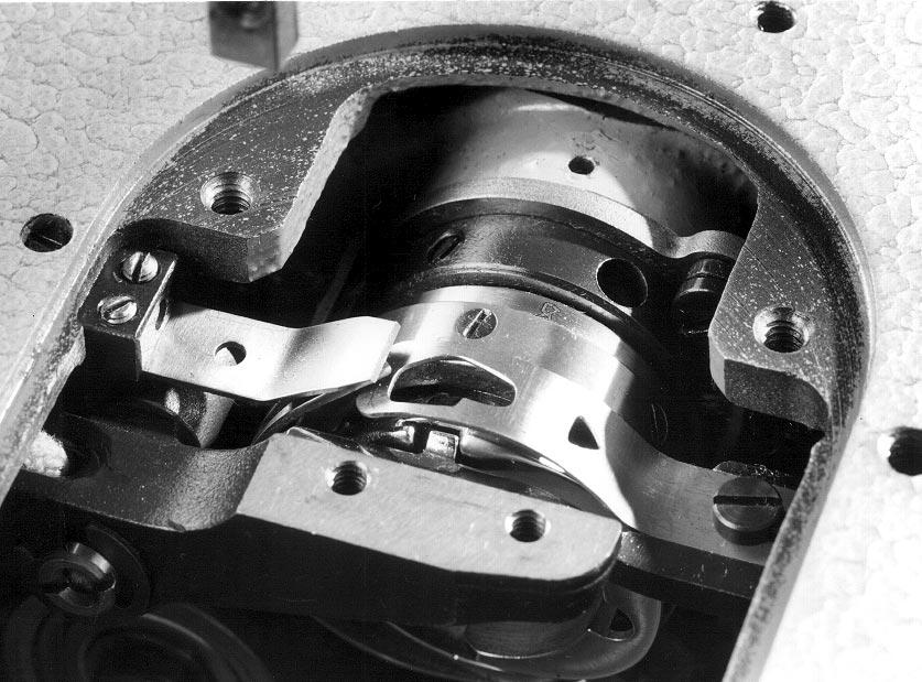
32 7. Shuttle-drive housing 4, /,7 mm 5 The shuttle-drive housing may only be adjusted with the sewing machine switched off. The shuttle-drive housing 4 is factory-aligned. It may only be altered in exceptional circumstances. With the shuttle-drive housing correctly aligned there must be a distance of 0.4 mm between the shuttle and the adjusting ring (see section 7.). The distance between the needle-plate surface and the thread-drawing plate 5 is: with the small shuttle =.7 mm ( / ) with the large shuttle =. mm ( / ) Loosen locking screw. Under the locking screw there is a stop screw. Adjust the stop screw. The distance between the needle-plate surface and the thread-drawing plate 5 is: with the small shuttle =.7 mm with the large shuttle =. mm The distance is checked with gauge. with the small shuttle = order no.: with the large shuttle = order no.: Retighten locking screw. Undo screws of the shuttle-drive housing. Move the shuttle-drive housing 4. Between the shuttle and the adjusting ring there must be a distance of 0.4 mm (see section 7.). Retighten screws of the shuttle-drive housing. Check the distance of the shuttle beak from the needle and adjust if necessary (see section 7.).
33 7. Bobbin-housing holder 4 The bobbin-housing holder is factory-aligned. When the holder has been replaced the new holder may need to be re-aligned. The bobbin-housing holder may only be adjusted with the sewing machine switched off. IMPORTANT Alignment may only be carried out in the cross-hatched area (see sketch). The extreme hardness in the region of the retaining tab means that there is a danger of breakage there. Align the bobbin-housing holder 4. The distance between retaining tab of the bobbin-housing holder 4 and the lower part of the bobbin-housing should be mm.


34 8. Thread clipper The control cam 4 determines the movement of the thread clippers and the timing of the blade movement. The timing thus coincides with the movement of the stitch-forming components. The thread clipper is switched on electromagnetically. 8. Control cam for timing the blade movement When the thread clipper is not in operation there must be a distance of 0. to 0. mm between the external diameter of the control cam 4 and the ball-race 6. With the machine locked in position D ball-race 6 must engage in the indentation 5 of the control cam 4 when manually pressed downwards. The control cam may only be adjusted with the sewing machine switched off. Undo fastening screws 7 of the magnet. Move magnet. The distance between control cam 4 and the ball-race 6 must be mm. The roller must be in contact with the ram. Retighten fastening screws 7 of the magnet. 7 Lock sewing machine in position D. Undo fastening screws of the control cam 4. Turn the control cam on the lower shaft. The ball-race 6 must engage in the indentation 5 of the control cam 4 when manually pressed downwards. The axial position should be such that the control cam 4 and roller 6 are opposite each other. Retighten fastening screws of the control cam 4. 4
35 8. Positioning the fixed blade The fixed blade must lie in the direction of the arrow on the screw (see sketch). Sharpened blades must be aligned as described in section 7.. The fixed blade may only be adjusted with the sewing machine switched off. Unscrew cutting-pressure screws. Undo screw from below. Push blade in the direction of the arrow against screw. Partially tighten screw from above. Adjust the cutting pressure (see section 8.6). Fully tighten screw from below. 5

36 8. Sharpening the fixed blade The cutting angle of the fixed blade 6 is 5 (see sketch). It is essential for sharpening to be carried out with a fine-grained whetstone. After sharpening the blade must be replaced with the sewing machine switched off. IMPORTANT Blades which have lost more than 0.5 mm of their original length through sharpening must be replaced. Undo screws and. The pre-tension of the fixed blade 6 is reduced. Remove the blade 6. Sharpen the blade. The cutting angle of the fixed blade is 5. Replace the blade. Align the blade so that the distance between the cutting edge 5 and the edge 4 of the opening in the needle plate is 8.5 mm. IMPORTANT When replacing a blade after sharpening it must not be allowed to make contact with the screw. Fully tighten screw. Re-adjust the at-rest position of the hooked blade (see section 8.5) and the cutting pressure (see section 8.6). 6
37 8.4 Thread-guide plate, adjusting plate 4 5 Thread-guide plate is used with the small shuttle, the adjusting plate 5 with the large shuttle. The thread-guide plate or adjusting plate 5 must point in the direction of the arrow on the screw (see sketch). In this position the radial distance between the thread-guide plate or adjusting plate 5 and the thread-drawing plate 4 of the shuttle must be 0.5 mm. There must be a radial distance of 0. mm between the thread-guide plate or adjusting plate 5 and the hooked blade. The thread-guide plate or adjusting plate may only be removed with the sewing machine switched off. IMPORTANT When the thread-guide plate (adjusting plate) has been fitted the distances to the thread-drawing plate 4 and hooked blade must be checked. Partly undo screw. Remove thread-guide plate or adjusting plate 5 for alignment. Align thread-guide plate or adjusting plate 5. Replace the thread-guide plate or adjusting plate 5 and secure with screw. 7
38 8.5 Hooked blade The hooked blade must lie against the two screws in the direction of the arrow. With the hooked blade in the at-rest position its tip 6 and the cutting edge 7 of the fixed blade 5 must be at the same level. During the blade movement the tip 6 of the hooked blade must be exactly beneath the tip of the triangle in the thread-guide plate 4. The hooked blade may only be adjusted with the sewing machine switched off. Manually swivel hooked blade upwards. Undo fastening screws of the hooked blade. Push the hooked blade in the direction of the arrow against the attachment screws. Retighten fastening screws. Undo screw 8. Adjust the at-rest position of the hooked blade. With the hooked blade in its at-rest position its tip 6 and the cutting edge 7 of the fixed blade 5 must be at the same level. Retighten screw 8. Operate the hooked blade manually. Check that the tip 6 of the hooked blade coincides with the tip of the triangle. For adjustment undo screws and align the hooked blade. note With the hooked blade properly adjusted its tip 6 moves along the line 9 during the cutting process. The dotted line 9 runs approximately between the centre of the needle and the shuttle beak. 8

39 , mm
40 8.6 Cutting pressure 4 5 The thread must be reliably severed with pressure as low as possible. Low cutting pressure minimises wear. Two of the thickest threads used must be severed simultaneously. The cutting pressure may only be adjusted with the sewing machine switched off. Loosen the cutting-pressure screws. Swivel the hooked blade 4 under the fixed blade. The cutting edge 5 of the hooked blade must be under the cutting edge of the fixed blade. Set the fixed blade against the hooked blade 4 by screwing in the cutting-pressure screws. Alternately lay the thread to be severed to the right and left. Adjust the appropriate cutting-pressure screw. If the spring no longer returns the cutting mechanism to its starting position, the cutting pressure is too great. Sharpen (see section 7.) or replace fixed blade. 40

41 9. Class 7/7: thread retractor If at the start of a seam the upper thread-end is supposed to be pulled through to the underside of the material, it must not be caught between the sewing foot and the material. The thread retractor ensures that the upper thread-end hangs loosely from the eye of the needle. The movement of the thread retractors takes place after the threads have been severed and before the sewing feet have been raised. The function can be set at the control. The thread retractor can be switched on and off with the rocker switch 9. At the end of the forward retraction movement the lever 4 should be in contact with the Vulkollan disc. The retraction movement should be completed without hindrance. The thread retractor may only be adjusted with the sewing machine switched off. Undo screws 7 and 8. Adjust magnet. At the end of the forward retraction movement the lever 4 should be in contact with the Vulkollan disc. Retighten screws 7 and 8. Undo screws. Adjust the retractor wire 6. The retraction movement should be completed without hindrance. Retighten screws. IMPORTANT If the thread retractor is being used together with the compensating hinged foot, transmission lever 4 must be replaced by transmission lever 5 (order no.: Z0 0084). 4


42 0. Class 7: edge cutter On sewing machines with this accessory the edge of the material can be cut during the sewing process. In sub-classes and it is mechanically driven. It is switched on and off by a manual lever or button. Programming the on-and-off function is described in the setting-up instructions, section. The sub-class is fitted with a separate electrical drive. The edge cutter must cut reliably with the pressure as low as possible. The edge cutter may only be adjusted with the sewing machine switched off Adjusting the position of the blades in the direction of sewing Undo screw. Adjust blade holder 0. The point at which the blade begins to cut can be set in front of and behind the needle. Retighten screw.. Adjusting the cutting position Swivel the upper blade 5 down manually with the Allen key 7 (cylinder 9 extended). Secure the position with gauge 8. gauge 8 order no.: Z On sewing machines with a manual lever the manual lever is used to adjust the position of the upper blade. Move the upper blade 5 to BDC with the handwheel. With sub-class this is done with the knurled screw on the separate drive motor (see arrow). 4
43 Undo screw. Adjust block. The upper blade 5 should be parallel to the lower blade 6. IMPORTANT When the block is turned it should be constantly pressed upwards and brought to rest against the ledge of the blade bar 5. Retighten screw.. Adjusting the blade-height position Remove cover. Swivel the upper blade 5 down manually with the Allen key 7 (cylinder 9 extended). Secure the position with gauge On sewing machines with a manual lever the manual lever is used to adjust the position of the upper blade. Move the upper blade 5 to BDC with the handwheel. With sub-class this is done with the knurled screw on the separate drive motor. Undo screw 4. Adjust the height of blade bar 5. When the blade is at BDC the edge of the blade should be at the same level as the lower blade. Retighten screw 4. Check the blade position at TDC. At TDC the tip of the blade should still be in contact with the lower blade. 4. Adjusting the cutting pressure Undo threaded pin 4. Adjust screw. Move the upper blade against the lower blade. The edge cutter should cut reliably with the minimum possible pressure. Retighten threaded pin 4. Use the Allen key to carry out a manual cutting test. Re-adjust the position and cutting pressure if necessary. 4
44 0. Replacing the sewing equipment The fitments should be selected in the light of the desired sewing result. The feed dog, slider and foot should be replaced or adjusted as required. Fitments may only be replaced with the sewing machine switched off. Replacing the sewing equipment (without replacing the needle plate) Remove the foot and slider. Remove screws 7. The centring sleeve 9 ensures that the position of the needle plate is correct. The screw 8 must not be undone. Remove needle plate 6. Replace the sewing equipment. Replace needle plate 6. Retighten screws 7. Carry out a manual cutting test and if necessary re-adjust the blade as described in section 9. Replace the foot and slider. Replacing the sewing equipment (with replacement of the needle plate) Remove the foot and slider. Remove screw 7 and screw 8 with centring sleeve 9. Remove needle plate 6. Undo screw. Replace the sewing equipment. 44
45 Adjust the guide 4. The guide must be adapted to the width of the needle plate (cutting width). Fit new needle plate 6. Replace screw 7 and screw 8 with centring sleeve 9. Align needle plate. The feed dog should run in the centre of the needle-plate slits. Retighten screws 8 and 7. Move the guide 4 against the lower blade. Retighten screw. Align the upper blade to the lower blade. See section 9. Carry out a manual cutting test and if necessary re-adjust the blades. Replace the foot and slider. 0. Adjusting the indicator bracket The tip of the indicator bracket indicates where the blade starts to cut. The indicator bracket may only be adjusted with the sewing machine switched off. Adjusting the indicator bracket Undo screws and 4. Adjust the indicator bracket. The height adjustment should be such that the material passes freely beneath the bracket (use the thickest material). The front edges of the bracket and the blade must be in line with each other. Retighten screws and 4. 45

46 0. Sharpening or replacing the blades 4 5 The blade should cut reliably with the minimum possible pressure. Replace the blade with the sewing machine switched off. Replacing the upper blade Undo screws 4 and 5. Remove upper blade or. Sharpen the upper blade. IMPORTANT Only the surface marked with the arrow may be sharpened. Replace the upper blade. Retighten screws 4 and 5. Carry out a manual cutting test and if necessary re-adjust the upper blade as described in section 9. Check the blade overlap at TDC. If sharpening the upper blade has made it too short (the tip no longer makes contact with the lower blade) a new blade must be fitted. 6 Replacing the lower blade Remove the slider, foot and needle plate. Undo screws. Remove lower blade 6. Sharpen the lower blade. IMPORTANT Only the surface marked with the arrow may be sharpened. Replace lower blade 6. The cutting edge must make contact with the upper blade. Retighten screws. Replace the slider, foot and needle plate. 46

47 . Class 7: cross-cutter On sewing machines with this attachment an incision transverse to the direction of sewing can be made in the material at every 6th stitch. The cross-cutter should cut reliably with the minimum possible pressure. The cross-cutter may only be adjusted with the sewing machine switched off. On completion of the adjustments the cover must be replaced. Adjusting the cutting depth Undo screws 6. Adjust the thrust piece 7 and counter-blade. The tip of the thrust piece 7 and the tip of the counter-blade should be level with the top of the needle plate. Retighten screws 6. Undo stud bolt 4 and screw. Adjust bearing block 5. The front of the counter-blade should move towards the operator and make contact with the needle plate. When the cutting movement is carried out the tip of the movable blade should move past the pressure foot and the needle plate at a minimum distance. After the adjustment has been carried out the back edge of the bearing block 5 must once more be parallel to the back edge of the base plate. This adjustment transverse to the feed direction maximises the cutting depth. To reduce the cutting depth the bearing block 5 must be moved to the right. Retighten stud bolt 4 and screw. 47


48 0,5 mm ca. mm Adjusting the blade lift Move the manual lever to the left. The cross-cutter is switched on. Turn the handwheel. The roller should be at the highest point of the cam disc. In this position there should be a distance of about mm between the locknut 9 and the cover plate 0. Unscrew the toggle link socket 6. Undo locknut 7. Adjust the distance by lengthening or shortening the connecting rod 8. The toggle link socket must be rotated accordingly. IMPORTANT The connecting rod 8 must be firmly screwed into the toggle link socket as far as it will go. Retighten locknut 7. Replace toggle link socket 6. Turn the handwheel. The roller should be completely clear of the cam. The blade is at its highest position. Undo screw 4. Adjust stop 5. Between the stop 5 and the blade lever there should be a distance of 0.5 mm. Retighten screw 4. Adjusting the timing of the blade movement Depending on the thickness of the material the timing of the cutting movement of the movable blade must be such that the blade does not touch the material until the moment when the feed process has been completed. Undo screws. Turn worm. Retighten screws. 48

49 4 5 Adjusting the cutting pressure Undo screw 4. Adjust bearing bush 5. The driver pin of the blade lever should make intimate contact with the counter-blade. Retighten screw 4. Undo locknut. Adjust the cutting pressure by turning the screw. The blade should cut reliably with the minimum possible pressure. IMPORTANT Heavy cutting pressure causes excessive blade wear. Retighten locknut Replacing the cam disc The cross-cutter can be fitted with various cam discs to permit varying distances between the incisions. order no.: incision after every 4th stitch after every 6th stitch after every th stitch Move the manual lever to the right. The cross-cutter is switched off. Undo threaded pins 7 and 8 of the cam disc 6. Remove cam disc 6 upwards. Fit new cam disc onto the shaft 9 as far as the shoulder. Tighten threaded pins 7 and 8. The threaded pin 8 must press on the surface 0 of the shaft. This ensures that the timing of the blade movement will be correct. 49

50 . Class 75: differential foot overfeed. Adjusting the overfeed-foot travel 4 Sewing machines of class 75 enable an extra layer of material to be processed. If the sewing machine is in position B and a stitch length of 4 mm is set, the overfeed foot must not move when the overfeed guide is swivelled. If the sewing machine is in position B the advance lever should be vertical. The feed may only be adjusted with the sewing machine switched off. Adjusting the feed. Adjusting the thrust cam Set stitch length to 4 mm. Remove bobbin-winder cover. Lock sewing machine in position B. Undo screws of thrust cam 4. Rotate the thrust cam on the arm shaft. Retighten screws of thrust cam 4.. Adjusting the advance lever Set the stitch length to 4 mm. Remove bobbin-winder cover. Lock sewing machine in position B. Undo screws of the locking hub. Move the advance lever to the vertical. Retighten screws of the locking hub. 50
51 .. Synchronisation of overfeed foot and feed dog 4 Set the stitch length to 4 mm for the feed dog and the overfeed foot. Turn the sewing machine on with the handwheel. During the overfeed-foot working phase the overfeed foot and feed dog must be synchronised. Synchronisation may only be adjusted with the sewing machine switched off. Set the stitch length to 4 mm for the feed dog and the overfeed foot. Remove bobbin-winder cover. Undo screw of the clamping lever 4. Rotate guide (insert pin in hole ). Rotation in the + direction increases the overfeed. Rotation in the - direction decreases the overfeed. Once the overfeed and underfeed are synchronised, retighten screw of the clamping lever 4. 5
52 . Adjusting the overfeed-foot lift.. Adjusting the overfeed-foot eccentric In position E the lift cam should be aligned groove-to-groove with the connecting rod. The lift may only be adjusted with the sewing machine switched off. Remove bobbin-winder cover. Lock sewing machine in position E. Undo screws of the lift cam. Turn lift cam. The groove should be in line with the groove of the locking hub. Retighten screws of the lift cam. 5

53 .. Adjusting the overfeed lift height The overfeed foot has a maximum lift of mm. In position E the distance between the foot-attachment block 5 and the bearing block 4 of the rocker lever is 7 mm. The lift may only be adjusted with the sewing machine switched off. 8 mm Remove cover. Lock sewing machine in position E. Undo screw. Move bearing block 4. The distance between the foot-attachment block 5 and the bearing block 4 should be 7 mm. Note: The foot-attachment block must be in close contact with the pressure bar. Retighten screw. 9 Undo screw 6 of the locking hub 7. Rotate lifting shaft. The overfeed foot 8 should have a maximum lift of mm to the needle plate 9. Retighten screw 6. 5
 can be altered to suit the material. The inclination of the overfeed foot may only be adjusted with the sewing machine switched off. Undo threaded pins.")
54 .. Position of the overfeed foot The overfeed foot is adjusted at the factory so that light and medium-weight material is laid on the feed dog in parallel. The lay (inclination) can be altered to suit the material. The inclination of the overfeed foot may only be adjusted with the sewing machine switched off. Undo threaded pins. Insert the trunnion further into the advance shaft or partly extract it. This adjusts the inclination of the overfeed foot. Retighten threaded pins. IMPORTANT After the inclination of the overfeed has been adjusted the lift must be checked and corrected if necessary. See section... 54
55 . Adjusting the extra-thickness operating lever If the extra-thickness indicator lever has been set to 8 mm by turning the knurled knob, the pin 6 should be in the hole of the upper guide 7 on sheet 5. Adjust the operating lever with the sewing machine switched off. Set the adjustable extra-thickness stop to 8 mm. Undo locking screw 4 of the operating lever. Press the extra-thickness indicator lever against the adjustable extra-thickness stop. Rotate the knurled knob until there is a distance of to mm to the knurled knob of the adjustable extra-thickness stop. Press the upper guide 7 against stop 5 with the pin 6. Tighten locking screw 4 of the operating lever. Set the extra-thickness indicator lever to 4 mm by turning the knurled knob and check synchronisation with the feed dog (the basic stitch-length must also be set to 4 mm). If an adjustment is necessary, proceed as in section... 55

56 . Replacing the arm-shaft bearing The right-hand arm-shaft bearing must be replaced if the arm shaft is running stiffly. Replace the arm-shaft bearing with the sewing machine switched off. IMPORTANT Do not use an extractor tool When the right-hand arm-shaft bearing is removed and replaced no axial pressure must be exerted on the arm shaft. Axial pressure in the direction of the cover will damage the thread lever. Replacing the arm-shaft bearing Remove the position sensor, handwheel, belt protector and cover. Remove the V-belt and retaining springs. Remove retaining ring 6. Undo screws and 4. Push the synchronous belt off the upper synchronous-belt pulley to the left. Prise off the drive unit with screwdrivers or similar. The drive unit consists of: synchronous-belt pulley, V-belt pulley and ball-race. Remove V-belt pulley. Remove the synchronous-belt pulley and replace it completely (order no.: ), or remove the ball-race 5 with an extraction device and press on a new ball-race (order no.: ). Replace V-belt pulley. Replace drive unit. Replace the parts which have been removed. IMPORTANT The sewing machine must be re-adjusted after the arm-shaft bearing has been replaced. 56

57 4. Lubrication The oil level must not fall below the "minimum" mark. Work on the oil-circulation system may only be carried out with the sewing machine switched off. Oil can cause skin rashes. Avoid protracted contact with the skin. In the event of contact, thoroughly wash the affected area. IMPORTANT The handling and disposal of mineral oils is subject to legal regulations. Used oil must be delivered to an authorised acceptance point. Protect the environment. Take care that no oil is spilled. Top up the oil reservoir to the "maximum" mark. - For shuttle lubrication see section. - The oil reservoir should be topped up only with ESSO SP-NK 0 lubricating oil or an equivalent oil with the following specification: viscosity at 40 C: 0 mm /s flashpoint: 50 C ESSO SP-NK 0 can be obtained from DÜRKOPP-ADLER AG sales outlets under the following parts nos.: -litre container: litre container:
58 4. Oil circulation The oil passes from the oil reservoir 5 to the sump, from where the lubrications points in the arm and sewing-head regions are supplied with oil. The oil thrown off by the crank mechanism passes along the wick to the central distributor pipe 4 for the lubrication points located under the base plate. Excess oil drips into the oil-collection tray 6 and is returned to the sump by the pump. This provides effective lubrication with minimum oil consumption. Work on the oil-circulation system may only be carried out with the sewing machine switched off. IMPORTANT After work is completed it is essential to ensure that the hoses are correctly reconnected to the pump. S = suction D = pressure 58

59 4. Shuttle lubrication If shuttle lubrication is checked with the sewing machine switched on, the utmost care must be taken. Shuttle lubrication may only be adjusted with the sewing machine switched off. The oil quantity required for shuttle lubrication varies with the sewing yarns and material to be processed. A piece of paper - ideally blotting paper - held beneath the shuttle should be lightly sprayed with oil when a seam about m long is sewn at full speed using the intended threads and material. Adjust screw : anti-clockwise clockwise = more oil = less oil = shuttle-lubrication oil reservoir 59
 can be found in the motor manufacturer s detailed operating manual. 5.")
60 5. Control and operating panel 5. Control and QUICK operating panel In this service manual only the most important aspects of the control system are described. A detailed description (parameter list and description) can be found in the motor manufacturer s detailed operating manual. 5.. Changing settings To ensure that the settings are not inadvertently altered they can only be changed by gaining access to the technician level. G G - - Access to the technician level Simultaneously press the "G" and "-" keys and hold them down. Turn on the main switch and release both keys. "* " appears in the display. Hold down the "G" key and press "-". "INPUT" appears in the display. The technician-level settings can now be changed. The drive is inoperative. G F + - Changing settings Press the "G" key. The group is selected. Press the "F" key. The setting is selected. Press the "+" key. The selected value is increased. Press the "-" key. The selected value is decreased. G - Hold down the "G" key and press the "-" key. " *MANUAL " appears in the display. The drive is again operative. 60
61 5.. RESET RESET restores all settings to their factory-set values. G F Push the pedal fully forwards (step ). Simultaneously press and hold down the "G", "F", "+" and "-" keys on the control field. Turn on the main switch. "RESET +/-" appears in the display. Press the "+" key. All settings are restored to their factory-set values. IMPORTANT The "700" setting - position-sensor reference point - is not reset. The "70" and "70" settings must be checked and corrected if necessary. 6
 can be found in the motor manufacturer s detailed operating manual. 5.")
62 5. Control and EFKA operating panel In this service manual only the most important aspects of the control system are described. A detailed description (parameter list and description) can be found in the motor manufacturer s detailed operating manual. 5.. Changing settings To ensure that the settings are not inadvertently altered they can only be changed on gaining access to the technician level. P 9 E 0 7. Selecting adjustment mode Press and hold down the "P" key. Turn on the main switch. "C-0000" appears in the display. Release the "P" key. The first digit of the code number flashes.. Changing to technician level Enter code number "907" with the number keys "0..9". Press the "E" key. The control unit switches to technician level. The first parameter ("F-00") appears in the display. The technician-level parameters can now be changed. If an incorrect code number is entered the text "C-0000 InFo F" appears. The entry must be repeated. 0 E Selecting the desired parameters Press the number keys "0..9". The parameter no. is selected. Press the "E" key. The selected parameter number (e.g. "F-00") appears in the first line. The brief designation of the parameter and its value (e.g. "SSc 00") appear in the second line. If an incorrect parameter number is entered the text "F-XXX InFo F" appears. The entry must be repeated. 6
ENGINEER S MANUAL No.01
 1-NEEDLE, UNISON FEED, LOCKSTITCH MACHINE (AUTOMATIC LUBRICATION) LU-1510 1-NEEDLE, UNISON FEED, LOCKSTITCH MACHINE WITH AUTOMATIC THREAD TRIMMER (AUTOMATIC LUBRICATION) LU-1510-7 1-NEEDLE, UNISON FEED,
IMPORTANT SAFETY INSTRUCTIONS
 CONTENTS 1.SPECIFICATIONS... 1 2.INSTALLATION... 1 3.INSTALLATION OF THE SYNCHRONIZER... 2 4.ASSEMBLY OF HAND WHEEL... 2 5.INSTALLATION OF HAND WHEEL... 2 6.INSTALLING THE BELT COVER... 3 7.ADJUSTING THE
Model PLK-G5050 PLK-G10050
 Industrial Sewing Machine TECHNICAL MANUAL SEWING MACHINE HEAD Electronic Pattern Sewing Machine Model PLK-G5050 PLK-G10050 A180E686P01 FOR SAFE USE Before the installation, operation, and inspection for
Part 2: Installation Instructions cl
 Contents Page: Part 2: Installation Instructions cl. 381-382 1. Delivery scope............................... 3 2. General and Transportation safety precautions........... 3 3. Stand installation 3.1 Installing
Part 1: class 69 operating instructions
 Contents Page: Preface and general safety instructions Part 1: class 69 operating instructions 1. Product description............................ 5 2. Designated use.............................. 5 3.
MSK-8900M Industrial Sewing Machine. Instruction Manual
 MSK-8900M Industrial Sewing Machine Instruction Manual CONTENTS Operation instruction. Brief introduction. Main specifications. Main parts name 4. The method of installation 5 5. Pareparation before sewing
Industrial Sewing Machine TECHNICAL MANUAL MECHANICAL VERSION. Electronic Pattern Sewing Machine. Model PLK-E2010R A180E530P01
 Industrial Sewing Machine TECHNICAL MANUAL MECHANICAL VERSION Electronic Pattern Sewing Machine Model PLK-E2010R A180E530P01 FOR YOUR SAFETY! If you are operating the sewing machine for first time, please
Industrial Sewing Machine TECHNICAL MANUAL SEWING MACHINE HEAD. Electronic Pattern Sewing Machine. Model PLK-G2516 A180E621P01
 Industrial Sewing Machine TECHNICAL MANUAL SEWING MACHINE HEAD Electronic Pattern Sewing Machine Model PLK-G2516 A180E621P01 FOR SAFE USE Before the installation, operation, and inspection for this product,
Industrial Sewing Machine TECHNICAL MANUAL SEWING MACHINE HEAD. Electronic Pattern Sewing Machine. Model PLK-G1010 A180E593P03
 Industrial Sewing Machine TECHNICAL MANUAL SEWING MACHINE HEAD Electronic Pattern Sewing Machine Model PLK-G1010 A180E593P03 FOR SAFE USE Before the installation, operation, and inspection for this product,
PLC-1700 Series PLC-1710, , 1760, , 1760L
 Post-bed, Unison-feed, Lockstitch Machine PLC-1700 Series PLC-1710, 1710-7, 1760, 1760-7, 1760L ENGINEER S MANUAL 40040656 No.E372-00 Introduction This Engineer s Manual is for technical service engineers.
USER S MANUAL. SS-7350 Series. Small cylinder bed interlock sewing machine
 R USERS MANUAL SS-7350 Series Small cylinder bed interlock sewing machine R Best Quality Best Price Best Service 1. Thank you for purchasing our product. Based on the rich expertise and experience accumulated
Please read this manual before using the machine. Please keep this manual within easy reach for quick reference.
 INSTRUCTION MANUAL Please read this manual before using the machine. Please keep this manual within easy reach for quick reference. HIGH SPEED SINGLE NEEDLE STRAIGHT LOCK STITCHER Thank you very much for
Industrial Sewing Machine TECHICAL MANUAL SEWING MACHINE HEAD. Electronic Pattern Sewing Machine. Model PLK-G1010 A180E593P02
 Industrial Sewing Machine TECHICAL MANUAL SEWING MACHINE HEAD Electronic Pattern Sewing Machine Model PLK-G1010 A180E593P02 FOR SAFE USE Before the installation, operation, and inspection for this product,
DA-9270 TWIN NEEDLE (THREE NEEDLE) FEED OFF THE ARM DOUBLE CHAIN STITCHER. English
 FEED OFF THE ARM DOUBLE CHAIN STITCHER. English") TWIN NEEDLE (THREE NEEDLE) FEED OFF THE ARM DOUBLE CHAIN STITCHER English Thank you very much for buying a BROTHER sewing machine. Before using your new machine, please read the safety instructions below
TWIN NEEDLE (THREE NEEDLE) FEED OFF THE ARM DOUBLE CHAIN STITCHER English Thank you very much for buying a BROTHER sewing machine. Before using your new machine, please read the safety instructions below
MITSUBISHI. Industrial Sewing Machine. Model PLK-E1010 TECHNICAL MANUAL MECHANICAL VERSION. Electronic Pattern Sewing Machine A180E494P01
 MITSUBISHI Industrial Sewing Machine TECHNICAL MANUAL MECHANICAL VERSION Electronic Pattern Sewing Machine Model PLK-E00 A80E9P0 FOR YOUR SAFETY! If you operate the sewing machine first time, please make
Please read this manual before using the machine. Please keep this manual within easy reach for quick reference.
 DA-927A DA-928A INSTRUCTION MANUAL Please read this manual before using the machine. Please keep this manual within easy reach for quick reference. TWIN NEEDLE / THREE NEEDLE FEED OFF THE ARM DOUBLE CHAIN
PREMIER SERIES BY P1255RBL-18 P2339RBL-18
 PREMIER SERIES BY P1255RBL-18 P2339RBL-18 P2339RBL-18 P1255RBL-18 P2339RBL- P1255RB- P2339RBL- 1. P2339RBL 18 Machine casting components Line Part Number Description Qt. Notes 1 300 1002 Machine
DDL-8700B-7 INSTRUCTION MANUAL
 DDL-8700B-7 INSTRUCTION MANUAL I CONTENTS I. SPECIFICATIONS... 1 II. SET-UP... 3 1. Installation...3 2. Installing the pedal sensor...4 3. Connecting the connector...4 4. How to install the power plug...5
PARTS LIST. CoverPro 900CP & 1000CP
 PARTS LIST CoverPro 900CP & 00CP 1 5 2 7 9 3 6 11 20 23 12 13 1 19 21 2 26 17 16 1 22 15 25 1 No. Part number Description 1 79560300 Face cover unit 2 79501600 Face cover 3 0602006 Thread cutter unit 000115700
MB-1800 Series INSTRUCTION MANUAL
 MB-800 Series INSTRUCTION MANUAL CONTENTS!. SPECIFICATIONS... @. NAME OF EACH COMPONENT.... Name of the main unit... #. INSTALLATION... $. PREPARATION OF THE SEWING MACHINE...7. Attaching the needle...
USER S MANUAL. KM-1060BL Series KM-1060BL KM-1060BL-7 KM-1062BL KM-1062BL-7
 USER S MANUAL KM-1060BL Series KM-1060BL KM-1060BL-7 KM-1062BL KM-1062BL-7 R Best Quality Best Price Best Service 1. Thank you for purchasing our product. Based on the rich expertise and experience accumulated
Technical Data. Name: ERIKA Automat fully automatic machine to divide and to round dough pieces of the same size
 AUTOMAT MANUAL 1 Technical Data Name: ERIKA Automat fully automatic machine to divide and to round dough pieces of the same size Type Divisions Dough Portions (in ounces) Plate Nos. 3 30 1.0 3.5 #35 4/40A
Instruction Manual and Parts List. Ultra High Speed Overedge and Safety Stitch Machine
 Instruction Manual and Parts List Ultra High Speed Overedge and Safety Stitch Machine 32D 3M-04 3M-04 / KS 32M-05 34M-04 24M-24 24M-24 / KS 244M-24 25M-35 25M-35 / KH 25M-55 25M-55 / KH 25M-56 25H-56 /
DDL-900A INSTRUCTION MANUAL
 DDL-900A INSTRUCTION MANUAL COVERI CONTENTS I. SPECIFICATIONS... 1 II. SET-UP... 3 1. Installation...3 2. Installing the pedal sensor...4 3. Installing the power switch (for CE)...4 4. Connecting the connector...5
PLC-2700 Series INSTRUCTION MANUAL
 PLC-2700 Series INSTRUCTION MNUL CONTENTS 1. SPECIFICTIONS... 1 2. INSTLLTION... 4 2-1. Installation of the sewing machine...4 2-2. djusting the belt tension (PLC-2710, 2760, 2760L, 2765)...6 2-3. Pneumatic
BARRACUDA 200ZW PORTABLE WALKING FOOT SEWING MACHINE INSTRUCTION MANUAL
 BARRACUDA 00ZW PORTABLE WALKING FOOT SEWING MACHINE INSTRUCTION MANUAL THE BARRACUDA 00ZW PORTABLE WALKING FOOT SEWING MACHINE INSTRUCTION MANUAL MATERIAL IS OWNED BY RELIABLE AND MAY NOT BE REPRODUCED
SC-922 InStruCtIon Manual
 SC-922 Instruction Manual CONTENTS I. SPECIFICATIONS... 1 II. SET-UP... 1 1. Installing to the table...1 2. Installing the motor unit...2 3. Installing the control box...2 4. Installing the belt...3 5.
Please read this manual before using the machine. Please keep this manual within easy reach for quick reference.
 INSTRUCTION MANUAL Please read this manual before using the machine. Please keep this manual within easy reach for quick reference. SINGLE NEEDLE DIRECT DRIVE STRAIGHT LOCK STITCHER WITH THREAD TRIMMER
AK-154 INSTRUCTION MANUAL
 AK-154 INSTRUCTION MANUAL 1 CONTENTS 1. FEATURES... 1 2. INSTALLATION... 2 3. HOW TO SELECT THE FUNCTION OF AUTO-LIFTER... 5 4. OTHERS (Advanced edition)... 6 4-1. Function for reducing the presser foot
PARTS LIST. Specification code: (JAI 45231) (JA) (JCA) (JUK) (JHBV)
 (JA) (JCA) (JUK) (JHBV)") PARTS LIST Specification code: 832-711-004 (JAI 45231) 832-712-005 (JA) 832-713-006 (JCA) 832-714-007 (JUK) 832-716-009 (JHBV) 14 13 1 2 6 10 12 9 11 8 7 3 5 4 7 1 KEY PART NO. NO. NAME 1 832649011 Needle
PARTS LIST Specification code: 832-711-004 (JAI 45231) 832-712-005 (JA) 832-713-006 (JCA) 832-714-007 (JUK) 832-716-009 (JHBV) 14 13 1 2 6 10 12 9 11 8 7 3 5 4 7 1 KEY PART NO. NO. NAME 1 832649011 Needle
DDL-900BB INSTRUCTION MANUAL
 DDL-900BB INSTRUCTION MANUAL CONTENTS I. SPECIFICATIONS... 1 II. SET-UP... 3 1. Installation...3 2. Installing the pedal sensor...4 3. Installing the power switch (for CE)...5 4. Connecting the connector...6
LK3 B434E LK3-B434EX LK3 B434EX/SF Electronic Lockstitch Pattern Tacker Electronic Lockstitch Pattern Tacker with Stepping Foot
 LK3 B434E LK3-B434EX LK3 B434EX/SF Electronic Lockstitch Pattern Tacker Electronic Lockstitch Pattern Tacker with Stepping Foot Specifications Model LK3 B434E LK3 B434EX LK3 B434EX / SF Application Thin,
DDL-900B INSTRUCTION MANUAL
 DDL-900B INSTRUCTION MANUAL CONTENTS I. SPECIFICATIONS... 1 II. SET-UP... 3 1. Installation...3 2. Installing the pedal sensor...4 3. Installing the power switch (for CE)...4 4. Connecting the connector...5
Service Documentation Market Release 7/84. Braun Kitchen machine KM 32 B 4209 with lamp
 Market Release 7/84 Braun Kitchen machine KM 32 B 4209 with lamp 4209 Exploded Drawing BAG Rev: 7/84 4209 4209-2 Service Information BAG Rev: 12/88 4209 Pos. No. Part Description Part Number 1 Male drive
CONTENTS 1. SPECIFICATIONS SET-UP FOR THE OPERATOR MAINTENANCE... 34
 ENGLISH ii CONTENTS. SPECIFICATIONS... 2. SET-UP.... Installing the motor unit... 2. Installing the control box... 3. Installing the belt... 2 4. Adjusting the pulley cover... 2 5. Installation and adjustment
KE-430HX KE-430HS BE-438HX
 KE-430HX KE-430HS BE-438HX INSTRUCTION MANUAL Please read this manual before using the machine. Please keep this manual within easy reach for quick reference. ELECTRONIC DIRECT DRIVE LOCKSTITCH BAR TACKER
Altra Series Dampener
 Crestline TM Altra Series Dampener Installation Instructions Heidelberg MO X88-66 10/97 Rev-A GENERAL INFORMATION ATTENTION CRESTLINE ALTRA SERIES TM DAMPENER OWNER! Accel Graphic Systems provides parts
Crestline Dampening System
 Crestline Dampening System Installation Instructions Hamada 500, 600, 700, E-47, SU47 Series Parent Press X88-25 01/2001 Rev-C 2593 GENERAL INFORMATION ATTENTION CRESTLINE DAMPENER OWNER! Accel Graphic
C-IV 60 CEILING FAN READ AND SAVE THESE INSTRUCTIONS. FAN RATING AC 120V. 60Hz
 C-IV 60 CEILING FAN READ AND SAVE THESE INSTRUCTIONS FAN RATING AC 120V. 60Hz Please do not use any electric or battery powered tools in the assembly and installation of this or any Matthews Fan Company
Liste de pièces Lista de Piezas Parts List
 H74 Liste de pièces Lista de Piezas Parts List 104 23 73-96 17 Nov 2011 A 2 Singer H74 Pos Part No Description 1 416484501 THREAD TAKE UP LEVER COMPLETE 2 416147701 THREAD TAKE UP LEVER SUPPORTER 3 416116001
INSTALLATION AND MAINTENANCE OF THE "THOMPSON-BRITISH" AUTOMATIC PLATEN
 INSTALLATION AND MAINTENANCE OF THE "THOMPSON-BRITISH" AUTOMATIC PLATEN Installation and Maintenance of The "Thompson-British" Auto Platen Lifting Bolt. Motor. Direction of rotation. Oiling. The machine
Household devices, <-<>al breaker rolls, stone crusher, four early types of power devices.
 SECTION VI Nos. 81 06 Household devices,
Hakki Pilke Raven spare parts manual
 1 ENGLISH Hakki Pilke Raven spare parts manual Valimotie 1, FI-85800 Haapajärvi, FINLAND Tel. +358 8 772 7300, Fax +358 8 772 732 info@maaselankone.fi, www.maaselankone.fi 2 Table of contents 1 Upper section
888 Operating Instructions
 888 Operating Instructions All rights reserved. Property of Dürkopp Adler AG and copyrighted. Reproduction or publication of the content in any manner, even in extracts, without prior written permission
Instructions, complete. Operating Instructions. Installation Instructions. Service Instructions
 506-3 Instructions, complete Operating Instructions Installation Instructions Service Instructions 2 3 Postfach 7 03 5, D-33703 Bielefeld Potsdamer Straße 90, D-3379 Bielefeld Telefon +49 (0) 52 / 9 25-00
DOCUMENT CREASING MACHINE
 DOCUMENT CREASING MACHINE OPERATORS MANUAL Morgana Systems Limited Snowdon Drive Winterhill Milton Keynes Buckinghamshire MK6 1AP United Kingdom Telephone: ( 01908 ) 608888 Facsimile: ( 01908 ) 692399
Spezialnähmaschine. Bedienanleitung. Operating Instructions. Instructions de maniement
 367 Spezialnähmaschine Bedienanleitung Operating Instructions Instructions de maniement D GB F Postfach 17 03 51, D-33703 Bielefeld Potsdamer Straße 190, D-33719 Bielefeld Telefon +49 (0) 5 21/ 9 25-00
Cleaning unit for coolant. :_decftez`_>r_fr] Book No.: V2
![Cleaning unit for coolant. :_decftez`_>r_fr] Book No.: V2](/thumbs/90/104143238.jpg "Cleaning unit for coolant. :_decftez`_>r_fr] Book No.: V2") Cleaning unit for coolant :_decftez`_>r_fr] Book No.: 1271526-02 V2 Alfa Laval Separation AB Separator Manuals, dept. SKEL S-147 80 Tumba, Sweden Telephone: +46 8 53 06 50 00 Telefax: +46 8 53 03 10 40
Cleaning unit for coolant :_decftez`_>r_fr] Book No.: 1271526-02 V2 Alfa Laval Separation AB Separator Manuals, dept. SKEL S-147 80 Tumba, Sweden Telephone: +46 8 53 06 50 00 Telefax: +46 8 53 03 10 40
Please read this manual before using the machine. Please keep this manual within easy reach for quick reference.
 INSTRUCTION MANUAL Please read this manual before using the machine. Please keep this manual within easy reach for quick reference. ELECTRONIC DIRECT DRIVE LOCKSTITCH BUTTON HOLER Thank you very much for
INSTRUCTION MANUAL. This instruction manual applies to machines from the following serial numbers onwards: #
 245 246 INSTRUCTION MANUAL This instruction manual applies to machines from the following serial numbers onwards: # 6 500 24 296-2-9 99/002 Betriebsanleitung engl. 05.2 This Instruction Manual is valid
PARTS REFERENCE LIST MODEL: PR650/PR650C
 Home Sewing Machine PARTS REFERENCE LIST MODEL: PR650/PR650C CONTENTS (1) PRINCIPAL PARTS... 2 (2) UPPER SHAFT MECHANISM... 4 (3) NEEDLE BAR MECHANISM... 6 (4) NEEDLE BAR CHANGE MECHANISM... 10 (5) THREAD
AMS-224EN6060 / IP-420 INSTRUCTION MANUAL
 AMS-224EN6060 / IP-420 INSTRUCTION MANUAL * This Instruction Manual only describes the functions which are different from those of the AMS-224EN/IP-420. In order to use the AMS-224EN6060 safely, please
RH-981A ENGLISH ELECTRONIC EYELET BUTTON HOLER
 ENGLISH ELECTRONIC EYELET BUTTON HOLER Thank you very much for buying a BROTHER sewing machine. Before using your new machine, please read the safety instructions below and the explanations given in the
MNEFDD54 & MNBCDD54 GALVANIZED WALL FANS Installation, Operation, and Maintenance Instructions
 FARM PRODUCTS DIVISION MEMBER OF AMCA AMERICAN COOLAIR CORPORATION P.O. BOX 2300 JACKSONVILLE, FLORIDA 32203 PHONE (904) 389-3646 FAX (904) 387-3449 E-MAIL - fans@coolair.com MNEFDD54 & MNBCDD54 GALVANIZED
52 CEILING FAN READ AND SAVE THESE INSTRUCTIONS FAN RATING AC 120V.
 Irene 52 CEILING FAN READ AND SAVE THESE INSTRUCTIONS FAN RATING AC 120V. 60Hz TABLE OF CONTENTS Tools and Materials Required... 1 Package Contents... 1 Safety Rules... 2 Mounting Options... 3 Hanging
/11, -14/31 INSTRUCTION MANUAL. This instruction manual applies to machines from the following serial numbers onwards: #
 3834-4/, -4/3 INSTRUCTION MANUAL This instruction manual applies to machines from the following serial numbers onwards: # 2 733 53 296-2-8 936/002 Betriebsanleitung engl. 06.09 This Instruction manual
60" Lyndon Patio. Instruction Manual Customer Service :30 AM to 5:00 PM EST, Monday - Friday A Kichler Decor ceiling fan
 60" Lyndon Patio TM 310140 A Kichler Decor ceiling fan Includes wall mount control system Kichler Lighting 7711 East Pleasant Valley Road P.O. Box 318010 Cleveland, Ohio 44131-8010 Instruction Manual Customer
FD 430 Envelope Sealer
 FD 430 Envelope Sealer 1/2018 OPERATOR, MAINTENANCE, & PARTS MANUAL REV. 1 2 CONTENTS 1 SAFETY INSTRUCTIONS... 5 1.1 Symbols and reference key... 5 1.2 Basic safety precautions... 6 1.3 Safety advice...
PARTS REFERENCE LIST MODEL: PR600II/PR600IIC PR620/PR620C
 Home Sewing Machine PARTS REFERENCE LIST MODEL: PR600II/PR600IIC PR620/PR620C CONTENTS (1) PRINCIPAL PARTS... 2 (2) UPPER SHAFT MECHANISM... 4 (3) NEEDLE BAR MECHANISM... 6 (4) NEEDLE BAR CHANGE MECHANISM...
Exploded View - Model J-7020M/J-7040M Miter Cut-off Saw Base
 22 Exploded View - Model J-7020M/J-7040M Miter Cut-off Saw Base Parts List - Model J-7020M/J-7040M Miter Cut-off Saw Base 1 J-5507591 Base, Machine 1 1-1 5512197 Plug, Drain (3/8in, PT) 2 5507592 Screw,
USER S MANUAL. SPS/E-1507 Series. Electronically Controlled Pattern Sewing Machine (Mechanical Part)
") R USERS MANUAL SPS/E-1507 Series Electronically Controlled Pattern Sewing Machine (Mechanical Part) R Best Quality Best Price Best Service 1. Thank you for purchasing our product. Based on the rich expertise
R USERS MANUAL SPS/E-1507 Series Electronically Controlled Pattern Sewing Machine (Mechanical Part) R Best Quality Best Price Best Service 1. Thank you for purchasing our product. Based on the rich expertise
DDL-9000A Series. Direct-drive, High-speed, Lockstitch Machine with Automatic Thread Trimmer. High-end model of JUKI 1-needle lockstitch machines
 DDL-9000A Series Direct-drive, High-speed, Lockstitch Machine with Automatic Thread Trimmer DDL-9000A Series High-end model of JUKI 1-needle lockstitch machines A genuine sewing machine which makes the
INSTRUCTION MANUAL. This instruction manual applies to machines from the following serial numbers onwards: and software version 0435/002.
 45 46 INSTRUCTION MANUAL This instruction manual applies to machines from the following serial numbers onwards: 7 6 454 and software version 0435/00. 96--9 30/00 Instruction Manual engl. 0.5 This instruction
KE-430D BE-438D ELECTRONIC DIRECT DRIVE LOCKSTITCH BAR TACKER ELECTRONIC DIRECT DRIVE LOCKSTITCH BUTTON SEWER
 KE-430D ELECTRONIC DIRECT DRIVE LOCKSTITCH BAR TACKER BE-438D ELECTRONIC DIRECT DRIVE LOCKSTITCH BUTTON SEWER Thank you very much for buying a BROTHER sewing machine. Before using your new machine, please
Please read this manual before using the machine. Please keep this manual within easy reach for quick reference.
 INSTRUCTION MANUAL Please read this manual before using the machine. Please keep this manual within easy reach for quick reference. ELECTRONIC LOCKSTITCH PATTERN TACKER WITH STEPPING FOOT AND PROGRAMMING
Installation Instructions
 Wood Blinds Installation Instructions Heartland Woods Heartland Woods w/ Continuum *Click on any page to return to the Table of Contents* Heartland Woods Wood Blinds Mounting Inside or Outside Window Frame
Ceiling Sweep Fan Assembly Instructions
 Ceiling Sweep Fan Assembly Instructions CSF Series Installation Note: This fan must be installed by a licenced electrical contractor Improperly installed ceiling sweep fans can be dangerous and expensive
Hatteras BayTM. Patio. Instruction Manual. Includes our new CoolTouch TM Control System Looks permanent, but goes wherever you go! U.S.
 Hatteras BayTM Patio A Kichler Décor ceiling fan Designed to coordinate with a popular Kichler Lighting collection. Includes our new CoolTouch TM Control System Looks permanent, but goes wherever you go!
ELECTRONICALLY PROGRAMMABLE LOCK STITCH MACHINE WITH CYLINDER ARM PROFILE Sll
 ELECTRONCALLY PROGRAMMABLE LOCK STTCH MACHNE WTH CYLNDER ARM PROFLE Sll ] BAS-3201. NSTRUCTON MANUAL (SU,MMARY OF MODEL BAS-320) * Model BAS-320 is an automatic sewing machine with a wide variety of practical
BL Series INSTRUCTIONS
 BL Series Models: EX5204/BL514 EX5204/BL515 EX5214/BL524 EX5214/BL525 EXT5214/BL524 EXT5214/BL525 EX5404/BL614 EX5404/BL615 EX5414/BL624 EX5414/BL625 EXT5214H/BL528 EXT5214H/BL529 Automatic Backlatcher
Grain crusher Universal. Purpose: This machine is designed for the crushing of grain in agricultural operation.
 Grain crusher Universal. Purpose: This machine is designed for the crushing of grain in agricultural operation. Operating instructions and parts catalogue This grain crusher provides you with a machine
MAINTENANCE MANUAL TAIYO SEIKI CO., LTD.
 MAINTENANCE MANUAL TAIYO SEIKI CO., LTD. Introduction This Maintenance Manual explains how to replace and adjust the major components of the Automatic Taping Machine when required in daily operation.
TECHNICAL INFORMATION B 890 and B 990 Rotary Irons (US Models)
") TECHNICAL INFORMATION B 890 and B 990 Rotary Irons (US Models) 2011 Miele USA Table of Contents A B C D 010 Warning and Safety Instructions... 5 1 General... 5 2 Touch Current Measurement... 6 3 Risk of
TECHNICAL INFORMATION B 890 and B 990 Rotary Irons (US Models) 2011 Miele USA Table of Contents A B C D 010 Warning and Safety Instructions... 5 1 General... 5 2 Touch Current Measurement... 6 3 Risk of
TCUT10UL 2.5 HP 10 Tile Saw Assembly & Operating Instructions
 TCUT10UL 2.5 HP 10 Tile Saw Assembly & Operating Instructions READ ALL INSTRUCTIONS AND WARNINGS BEFORE USING THIS PRODUCT. This manual provides important information on proper operation and maintenance.
DAGNY LK. Ceiling Mounted Rotational Fan READ AND SAVE THESE INSTRUCTIONS. FAN RATING AC 110V~60Hz
 DAGNY LK Ceiling Mounted Rotational Fan READ AND SAVE THESE INSTRUCTIONS FAN RATING AC 110V~60Hz Please do not use any electric or battery powered tools in the assembly and installation of this or any
TECHNICAL INFORMATION Touchtronic Clothes Dryers
 TECHNICAL INFORMATION Touchtronic Clothes Dryers Includes: T1302, T1303, T1322, T1329ci T1403 & T1405 2004 Miele This page intentionally left blank. Table of Contents GENERAL INFORMATION A. Warning and
MODEL: PR600II PR600IIC PR620 PR620C
 MODEL: PR600II PR600IIC PR620 PR620C Published: Nov.,2005 Revised: Nov.,2014 MODEL LIST Model Countries (Added Date) Country Code & Abbreviation of Country Name Meaning of "R" and "H" CONTENTS (1) PRINCIPAL
Post-bed, Unison-feed, Lockstitch Machine with Vertical-axis Large Hook PLC
 PLC-1700 Series Post-bed, Unison-feed, Lockstitch Machine with Vertical-axis Large Hook Most-advanced machine lineup best suited to the stitching process for heavy weight materials such as car seats and
1. SAFETY RULES WARNING WARNING. 8. Avoid placing objects in the path of the blades.
 1 1. SAFETY RULES 1. To reduce the risk of electric shock, insure electricity has been turned off at the circuit breaker or fuse box before beginning. 2. All wiring must be in accordance with the National
Please read this manual before using the machine. Please keep this manual within easy reach for quick reference.
 INSTRUCTION MANUAL Please read this manual before using the machine. Please keep this manual within easy reach for quick reference. SINGLE NEEDLE DIRECT DRIVE LOCK STITCHER WITH ELECTRONIC FEEDING SYSTEM
MODEL: PE770 Published: Jul.,2009 Revised: Feb.,2013
 MODEL: PE770 Published: Jul.,2009 Revised: Feb.,2013 MODEL LIST Model Countries (Added Date) PE770 USA, ARG, PRY, BRA120V, BRA220V (Feb / 2011) PE770 AUS&NZL (Jul / 2012) Country Code & Abbreviation of
The Sewing Machine Course
 The Sewing Machine Course Video 1 - The Sewing Machine Overview Part 1 - The right machine for you. Choosing a machine is a very important part in the hobby of sewing as this is the main piece of equipment
OWNERS MANUAL FOR MEC 300E ATA
 OWNERS MANUAL FOR MEC 300E ATA PLEASE READ AND FULLY UNDERSTAND THE INSTRUCTIONS PRIOR TO SETTING OR TUNING THE MACHINE. CAUTION: ANY MEC CLAY TARGET MACHINE MUST BE IN THE DISARMED STATE WITH THE BATTERY
BAS-300G-484 BAS-300G-484 SF
 BAS-300G-484 BAS-300G-484 SF DIRECT DRIVE PROGRAMMABLE ELECTRONIC PATTERN SEWER Please read this manual before using the machine. Please keep this manual within easy reach for quick reference.
CEILING FAN OWNER'S MANUAL
 Style that revolves around you. CEILING FAN OWNER'S MANUAL QUATRO 10/09 WARNING: Read and follow these instructions carefully and be mindful of all warnings shown throughout. GENERAL INSTALLATION & OPERATION
SuperKlean Washdown Products
 DURAREEL DR8 & DR8S INSTALLATION AND MAINTENANCE INSTRUCTIONS **DO NOT THROW AWAY AFTER INSTALLATION** **SAVE AND DISPLAY PROMINENTLY WHERE THIS EQUIPMENT IS USED** GENERAL WARNINGS High pressure and hot
Cable Drum Machine. Operation Manual 40 SERIES. Cleans 2" to 4" lines up to 75' N O T F O R R O O T S
 Cable Drum Machine Operation Manual 40 SERIES Cleans 2" to 4" lines up to 75' Used For: Sinks, Showers & Floor Drains N O T F O R R O O T S WARNING - Read All Instructions, When Using Electric Tools, Basic
60" Tulle PatioTM. Instruction Manual. A Kichler Select ceiling fan
 60" Tulle PatioTM A Kichler Select ceiling fan cul Certified for Wet Location Kichler Lighting 7711 East Pleasant Valley Road P.O. Box 318010 Cleveland, Ohio 44131-8010 Customer Service 866.558.5706 8:30
Installation instructions Refrigerators and freezers for integrated use, door-on-door
 Installation instructions Refrigerators and freezers for integrated use, door-on-door 010612 7084276-04 IK/ IKB/ IKP/ IG/ IGN... 1/ 3/ 6 General safety information Contents 1 General safety information...
CUTMASTER Strip Cutting Machine
 EASTMAN THE EASTMAN CUTMASTER Strip Cutting Machine WARNING Safety glasses must be worn at all times when operating or servicing this equipment. Instruction Manual & Illustrated Parts List Please read
Hanson LED C e i l i n g F a n
 Hanson LED C e i l i n g F a n model no. 052-8398-2 Toll-free 1-866-827-4985 IMPORTANT: For your safety please read and understand this manual before installing or operating this product. OWNER S MANUAL
Select. Sutter PlaceTM. Instruction Manual. A Kichler Select ceiling fan
 Sutter PlaceTM A Kichler ceiling fan Kichler Lighting 7711 East Pleasant Valley Road P.O. Box 318010 Cleveland, Ohio 44131-8010 Customer Service 866.558.5706 8:30 AM to 5:00 PM EST, Monday - Friday Instruction
MF-7500 Series. MF-7500D Series. High-speed, Flat-bed, Top & Bottom Coverstitch Machine. Semi-dry-head, Flat-bed, Top & Bottom Coverstitch Machine
 MF-7500 Series High-speed, Flat-bed, Top & Bottom Coverstitch Machine MF-7500D Series Semi-dry-head, Flat-bed, Top & Bottom Coverstitch Machine MF-753D-U11-B56 The MF-7500 Series is a newly developed coverstitch
ILLUSTRATIONS ARE FOR REFERENCE ONLY AND ARE SUBJECT TO CHANGE WITHOUT NOTICE ITEM P/N DESCRIPTION
 TC-0 TURN PLATE TC-0 TURN PLATE 0 0 0 TC-0-000 TURNTABLE TC-0-00 TURNTABLE, TC-0 TC-0-00 SCREW, M X TC-0-00 COVER, TC-0 TC-0-00 RETAINING PIN TC-0-00 CLAMP TC-0-00 CLAMP SEAT TC-0-0 CLAMP SEAT, TC-0 TC-0-00
Orrin. Instruction Manual. Includes our new CoolTouch TM Control System Looks permanent, but goes wherever you go! U.S.
 Includes our new CoolTouch TM Control System Looks permanent, but goes wherever you go! U.S. Patent Pending Orrin A Kichler Select ceiling fan Kichler Lighting 7711 East Pleasant Valley Road P.O. Box 318010
Operating Instructions Pigeon - Clay target launcher
 Operating Instructions Pigeon - Clay target launcher Specifications: Single column 50 target hopper. Throwing distance: 60 yards Weight: 25kg / 55 lbs Length: 1200mm / 47 Width: 560mm / 22 Height: 960mm
CEILING FAN OWNER'S MANUAL
 CEILING FAN OWNER'S MANUAL READ AND SAVE THESE INSTRUCTIONS MODEL: 52-135-5WA-13 FAN RATING AC 120V. 60Hz CUL LISTED MODEL : AC-552OD 1. TOOLS AND MATERIALS REQUIRED Philips screw driver Blade screw driver
RA 431 B Angled tube. As at: 01/15/10 Time:17:17
 Angled tube As at: 01/15/10 Time:17:17 Angled tube As at: 01/15/10 Time:17:17 Pos. Description Reference 01 Lower angled tube 436.255 02 Disk 436.340 03 Cylindrical screw M 10x35 P...487 HA 04 Upper handle
ALUMA INSTRUCTION MANUAL WARRANTY CERTIFICATE
 ALUMA BY INSTRUCTION MANUAL WARRANTY CERTIFICATE Manual design and all elements of manual design are protected by U.S. Federal and/or State Law, including Patent, Trademark and/or Copyright laws. The Minka-Aire
42 Kevlar. Instruction Manual. Kichler Lighting 7711 East Pleasant Valley Road P.O. Box Cleveland, Ohio
 42 Kevlar Kichler Lighting 7711 East Pleasant Valley Road P.O. Box 318010 Cleveland, Ohio 44131-8010 Customer Service 866.558.5706 8:30 AM to 5:00 PM EST, Monday - Friday Instruction Manual 1 1. SAFETY