Air-to-Water Hydromodule + Tank WH-UX12FE5 WH-UD12FE5 WH-UD16FE5. Destination Europe WARNING
|
|
|
- Oswald Green
- 5 years ago
- Views:
Transcription
1 Order : PAPAMY420CE Air-to-Water Hydromodule + Tank Indoor Unit WH-ADC26G6E5 Outdoor Unit WH-UX09FE5 WH-UX2FE5 WH-UD2FE5 WH-UD6FE5 Destination Europe WARNING This service information is designed for experienced repair technicians only and is not designed for use by the general public. It does not contain warnings or cautions to advise non-technical individuals of potential dangers in attempting to service a product. Products powered by electricity should be serviced or repaired only by experienced professional technicians. Any attempt to service or repair the products dealt with in this service information by anyone else could result in serious injury or death. PRECAUTION OF LOW TEMPERATURE In order to avoid frostbite, be assured of no refrigerant leakage during the installation or repairing of refrigerant circuit. Panasonic Corporation 204.
2 TABLE OF CONTENTS. Safety Precautions Specifications WH-ADC26G6E5 WH-UX09FE WH-ADC26G6E5 WH-UX2FE WH-ADC26G6E5 WH-UD2FE WH-ADC26G6E5 WH-UD6FE Features Location of Controls and Components Indoor Unit Outdoor Unit Dimensions Indoor Unit Outdoor Unit Refrigeration and Water Cycle Diagram Block Diagram WH-ADC26G6E5 WH-UX09FE5 WH-ADC69G6E5 WH-UX2FE WH-ADC26G6E5 WH-UD2FE5 WH-ADC26G6E5 WH-UD6FE Wiring Connection Diagram Indoor Unit Outdoor Unit Electronic Circuit Diagram Indoor Unit Outdoor Unit Printed Circuit Board Indoor Unit Outdoor Unit Installation Instruction Indoor Unit Outdoor Unit Operation and Control Basic Function Water Pump Pump Down Operation [Service Mode: 0] Flow Switch Indoor Unit Safety Auto Restart Control Indication Panel Indoor Back-Up Heater Control Heater Control for Tank Side Base Pan Heater Control (Optional) Tank Pre-thermo OFF control Sterilization Mode Heating Outdoor Ambient Thermo OFF Control Quiet Operation Anti Freeze Control External Room Thermostat Control (Optional) Three Ways Valve Control Two Ways Valve Control External OFF/ON Control Holiday Mode Dry Concrete Function Protection Control Protection Control for All Operations Protection Control for Heating Operation Protection Control for Cooling Operation Servicing Guide Open and Close Top Front Plate How to take out Bottom Front Plate Test Run Proper Pump Down Procedure Adjust Water Flow Rate with Water Pump Expansion Vessel Pre Pressure Checking How to Unlock Cool Mode Dry Concrete [SERVICE MODE: 03] EEPROM Factory Default Data Setup Procedure Maintenance Guide Troubleshooting Guide Refrigeration Cycle System Relationship between the Condition of the Air-to-Water Hydromodule + Tank and Air-to- Water Heatpump Outdoor Units and Pressure and Electric Current Breakdown Self Diagnosis Function Error Codes Table Self-diagnosis Method Disassembly and Assembly Instructions To Remove Top Plate To Remove Pressure Gauge and Control Panel To Remove Bottom Front Plate To Remove RCCB To Remove Transformer and Electronic Controller To Remove Pressure Relief Valve, Flow Switch and Air Purge Valve To Remove Water Pump To Remove Bottle Complete To Remove Anode Bar To Remove Water Filter Technical Data Operation Characteristics Heating Capacity Table Cooling Capacity Table Exploded View and Replacement Parts List Indoor Unit Outdoor Unit
3 . Safety Precautions Read the following SAFETY PRECAUTIONS carefully before perform any servicing. Electrical work must be installed or serviced by a licensed electrician. Be sure to use the correct rating and main circuit for the model installed. The caution items stated here must be followed because these important contents are related to safety. The meaning of each indication used is as below. Incorrect installation or servicing due to ignoring of the instruction will cause harm or damage, and the seriousness is classified by the following indications. WARNING CAUTION This indication shows the possibility of causing death or serious injury. This indication shows the possibility of causing injury or damage to properties. The items to be followed are classified by the symbols: This symbol denotes item that is PROHIBITED from doing. Carry out test run to confirm that no abnormality occurs after the servicing. Then, explain to user the operation, care and maintenance as stated in instructions. Please remind the customer to keep the operating instructions for future reference. WARNING. Do not use unspecified cord, modified cord, joint cord or extension cord for power supply cord. Do not share the single outlet with other electrical appliances. Poor contact, poor insulation or over current will cause electrical shock or fire. 2. Do not install outdoor unit near handrail of veranda. When installing outdoor unit at veranda of high rise building, child may climb up to outdoor unit and cross over the handrail and causing accident. 3. Do not tie up the power supply cord into a bundle by band. Abnormal temperature rise on power supply cord may happen. 4. Do not insert your fingers or other objects into the unit, high speed rotating fan may cause injury. (For Outdoor Unit) 5. Do not sit or step on the unit, you may fall down accidentally. (For Outdoor Unit) 6. Keep plastic bag (packaging material) away from small children, it may cling to nose and mouth and prevent breathing. 7. Do not use pipe wrench to install refrigerant piping. It might deform the piping and cause the unit to malfunction. 8. Do not purchase unauthorized electrical parts for installation, service, maintenance and etc.. They might cause electrical shock or fire. 9. Do not modify the wiring of outdoor unit for installation of other components (i.e. heater, etc.). Overloaded wiring or wire connection points may cause electrical shock or fire. (For Outdoor Unit) 0. Do not add or replace refrigerant other than specified type. It may cause product damage, burst and injury etc.. Do not use the hot water produced by the Tank Unit for drinking or food preparation. It may cause illness to the user. 2. Do not place containers with liquids on top of the Tank Unit. It may cause Tank Unit damage and/or fire could occurs if they leak or spill onto the Tank Unit. 3. For electrical work, follow local wiring standard, regulation and this installation instruction. An independent circuit and single outlet must be used. If electrical circuit capacity is not enough or defect found in electrical work, it will cause electrical shock or fire. 4. For water circuit installation work, follow to relevant European and national regulations (including EN6770) and local plumbing and building regulation codes. (For Tank Unit) 5. Engage dealer or specialist for installation. If installation done by the user is defective, it will cause water leakage, electrical shock or fire. 6. This is a R40A model, when connecting the piping, do not use any existing (R22) pipes and flare nuts. Using such same may cause abnormally high pressure in the refrigeration cycle (piping), and possibly result in explosion and injury. Use only R40A refrigerant. Thickness or copper pipes used with R40A must be 0.8 mm or more. Never use copper pipes thinner than 0.8 mm. It is desirable that the amount of residual oil is less than 40 mg/0 m. 7. When install or relocate Tank Unit / Outdoor Unit, do not let any substance other than the specified refrigerant, eg. air etc. mix into refrigerant cycle (piping). Mixing of air etc. will cause abnormal high pressure in refrigeration cycle and result in explosion, injury etc. 8. Install according to this installation instructions strictly. If installation is defective, it will cause water leakage, electrical shock or fire. 9. Install at a strong and firm location which is able to withstand the set s weight. If the strength is not enough or installation is not properly done, the set will drop and cause injury. 20. Do not use joint cable for Tank Unit / Outdoor Unit connection cable. Use specified Tank Unit / Outdoor Unit connection cable, refer to instruction CONNECT THE CABLE TO THE TANK UNIT / CONNECT THE CABLE TO THE OUTDOOR UNIT and connect tightly for Tank Unit / Outdoor Unit connection. Clamp the cable so that no external force will be acted on the terminal. If connection or fixing is not perfect, it will cause heat up or fire at the connection. 2. This equipment is strongly recommended to be installed with Residual Current Device (RCD) on-site according to the respective national wiring rules or country specific safety measures in terms of residual current. (For Tank Unit) 22. During installation, install the refrigerant piping properly before run the compressor. Operation of compressor without fixing refrigeration piping and valves at opened condition will cause suck-in of air, abnormal high pressure in refrigeration cycle and result in explosion, injury etc. 23. During pump down operation, stop the compressor before remove the refrigeration piping. Removal of refrigerant piping while compressor is operating and valves are opened will cause suck-in of air, abnormal high pressure in refrigerant cycle and result in explosion, injury etc. 3
4 WARNING 24. Tighten the flare nut with torque wrench according to specified method. If the flare nut is over tightened, after a long period, the flare may break and cause refrigerant gas leakage. 25. After completion of installation, confirm there is no leakage of refrigerant gas. It may generate toxic gas when the refrigerant contacts with fire. 26. Ventilate the room if there is refrigerant gas leakage during operation. Extinguish all fire sources if present. It may cause toxic gas when the refrigerant contacts with fire. 27. Only use the supplied or specified installation parts, else, it may causes unit vibrate loose, water leakage, electrical shock or fire. 28. If there is any doubt about the installation procedure or operation, always contact the authorized dealer for advice and information. 29. Select a location where in case of water leakage, the leakage will not cause damage to other properties. 30. When installing electrical equipment at wooden building of metal lath or wire lath, in accordance with electrical facility standard, no electrical contact between equipment and building is allowed. Insulator must be installed in between. 3. Any work carried out on the Tank Unit / Outdoor Unit after removing any panels which is secured by screws, must be carried out under the supervision of authorized dealer and licensed installation contractor. 32. This system is multi supply appliance. All circuits must be disconnected before accessing the unit terminals. (For Tank Unit) 33. For cold water supply has a backflow regulator, check valve or water meter with check valve, provisions for thermal expansion of water in the hot water system must be provided. Otherwise it will cause water leakage. (For Tank Unit) 34. The piping installation work must be flushed before Tank Unit is connected to remove contaminants. Contaminants may damage the Tank Unit components. 35. This installation may be subjected to building regulation approval applicable to respective country that may require to notify the local authority before installation. (For Tank Unit) 36. The Tank Unit must be shipped and stored in upright condition and dry environment. It may laid on its back when being moved into the building. 37. Work done to the Tank Unit after remove the front plate cover that secured by screws, must be carried out under the supervision of authorized dealer, licensed installation contractor, skilled person and instructed person. 38. This unit must be properly earthed. The electrical earth must not be connected to a gas pipe, water pipe, the earth of lightning rod or a telephone. Otherwise there is a danger of electrical shock in the event of an insulation breakdown or electrical earth fault in the Tank Unit / Outdoor Unit. CAUTION. Do not install the Tank Unit / Outdoor Unit at place where leakage of flammable gas may occur. In case gas leaks and accumulates at surrounding of the unit, it may cause fire. 2. Do not release refrigerant during piping work for installation, re-installation and during repairing a refrigeration parts. Take care of the liquid refrigerant, it may cause frostbite. 3. Do not install this appliance in a laundry room or other high humidity location. This condition will cause rust and damage to the unit. (For Tank Unit) 4. Make sure the insulation of power supply cord does not contact hot part (i.e. refrigerant piping, water piping) to prevent from insulation failure (melt). 5. Do not apply excessive force to water pipes that may damage the pipes. If water leakage occurs, it will cause flooding and damage to other properties. (For Tank Unit) 6. Do not transport the Tank Unit with water inside the unit. It may cause damage to the unit. 7. Carry out drainage piping as mentioned in installation instructions. If drainage is not perfect, water may enter the room and damage the furniture. (For Tank Unit) 8. Do not touch the sharp aluminium fin, sharp parts may cause injury. (For Outdoor Unit) 9. Select an installation location which is easy for maintenance. 0. Power supply connection to Tank Unit. Power supply point should be in easily accessible place for power disconnection in case of emergency. Must follow local national wiring standard, regulation and this installation instruction. Strongly recommended to make permanent connection to a circuit breaker. - Power Supply : Use approved 30A 2-poles circuit breaker with a minimum contact gap of 3.0mm. - Power Supply 2: Use approved 30A 2-poles circuit breaker with a minimum contact gap of 3.0mm.. Ensure the correct polarity is maintained throughout all wiring. Otherwise, it will cause electrical shock or fire. 2. After installation, check the water leakage condition in connection area during test run. If leakage occurs, it will cause damage to other properties. (For Tank Unit) 3. If the Tank Unit not operates for long time, the water inside the Tank Unit should be drained. 4. Installation work. It may need three or more people to carry out the installation work. The weight of Tank Unit might cause injury if carried by one person. It may need two or more people to carry out the installation work. The weight of outdoor unit might cause injury if carried by one person. 4
5 2. Specifications 2. WH-ADC26G6E5 WH-UX09FE5 Item Unit Outdoor Unit Performance Test Condition EN 45 Cooling Capacity Cooling EER Heating Capacity Heating COP ise Level Air Flow Refrigeration Control Device Condition (Ambient/Water) A35W7 kw 7.00 BTU/h kcal/h 6020 W/W 3.7 kcal/hw 2.72 Condition (Ambient/Water) A7W35 A2W35 kw BTU/h kcal/h W/W kcal/hw Condition (Ambient/Water) A35W7 A7W35 A2W35 db (A) Cooling: 49 Heating: 49 Power Level db Cooling: 67 Heating: 66 m 3 /min (ft 3 /min) Cooling: 89.5 (360) Heating: 76.8 (270) Expansion Valve Refrigeration Oil cm 3 FV50S (200) Refrigerant (R40A) kg (oz) 2.85 (00.6) Dimension Height mm (inch) 340 (52-3/4) Width mm (inch) 900 (35-7/6) Depth mm (inch) 320 (2-9/32) Net Weight kg (lbs) 0 (223) Pipe Diameter Liquid mm (inch) 9.52 (3/8) Gas mm (inch) 5.88 (5/8) Standard Length m (ft) 5 (6.4) Pipe Length Range m (ft) 3 (9.8) ~ 30 (98.4) I/D & O/D Height Difference m (ft) 20 (65.6) Additional Gas Amount g/m (oz/ft) 50 (0.5) Refrigeration Charge Less m (ft) 0 (32.8) Compressor Fan Heat Exchanger Type Motor Type Hermetic Motor Brushless (4-poles) Rated Output kw 3.00 Type Material Motor Type Propeller Fan PP DC (8-poles) Input Power W Output Power W 60 Fan Speed Fin material Fin Type rpm Cooling: 550 (Top), 590 (Bottom) Heating: 490 (Top), 530 (Bottom) Aluminium (Pre Coat) Corrugated Fin Row Stage FPI Size (W H L) mm
6 Power Source (Phase, Voltage, Cycle) Input Power Item Unit Outdoor Unit ø Single V 230 Hz 50 Condition (Ambient/Water) A35W7 A7W35 A2W35 kw Cooling: 2.2 Heating:.86 Heating: 2.5 Maximum Input Power For Heatpump System kw 5.4 Power Supply : Phase (Ø) / Max. Current (A) / Max. Input Power (W) Ø / 25.0 / 5.4k Power Supply 2 : Phase (Ø) / Max. Current (A) / Max. Input Power (W) Ø / 26.0 / 6.00k Power Supply 3 : Phase (Ø) / Max. Current (A) / Max. Input Power (W) / / Starting Current A 0.2 Running Current Condition (Ambient/Water) A35W7 A7W35 A2W35 A Cooling: 0.2 Heating: 8.6 Heating:.6 Maximum Current For Heatpump System A 25.0 Power Factor Power factor means total figure of compressor and outdoor fan motor. Power Cord Thermostat Protection Device % Cooling: 94 Heating: 94 Number of core - Length m (ft) - Electronic Control Electronic Control Item Unit Indoor Unit Performance Test Condition EN 45 Operation Range Internal Pressure Differential ise Level Dimension Outdoor Ambient Water Outlet C (min. / max.) C (min. / max.) kpa Condition (Ambient/Water) Cooling: 6 / 43 Heating: -20 / 35 Cooling: 5 / 20 Heating (Tank): - / 65*, Heating (Circuit): 25 / 55 Cooling: 20.0 Heating: 3.0 A35W7 A7W35 A2W35 db (A) Cooling: 33 Heating: 33 Power Level db Cooling: 46 Heating: 46 Height mm (inch) 77 (28-7/32) Width mm (inch) 598 (23-7/32) Depth mm (inch) 800 (70-27/32) Net Weight kg (lbs) 37 (302) Refrigerant Pipe Diameter Water Pipe Diameter Liquid mm (inch) 9.52 (3/8) Gas mm (inch) 5.88 (5/8) Room mm (inch) 28 (-3/32) Shower mm (inch) 9 (3/4) Water Drain Hose Inner Diameter mm (inch) 5 (9/32) Pump Hot Water Coil Motor Type. of Speed DC Motor 7 (Software Selection) Input Power W 93 Type Brazed Plate. of Plates 44 Size (H x W x L) mm 80 x 9 x 376 Water Flow Rate l/min (m 3 /h) Cooling: 20. (.2) Heating: 25.8 (.5) Pressure Relief Valve Water Circuit kpa Open: 300, Close: 265 and below Flow Switch Type Magnetic Lead Switch Set Point l/min. Pressure Release Valve kpa Open: 50±200, Close: 700 and below Protection Device A Residual Current Circuit Breaker (30) 6
7 Expansion Vessel Item Unit Indoor Unit Volume I 0 MWP bar 3 Capacity of Integrated Electric Heater / OLP TEMP kw / C 6.00 / 80 Tank Volume (Spec / Nett) L 200 / 85 Max. Tank Water Set Temperature C 65 Tank Coil Surface m 2.8 Maximum Working Pressure Operating Pressure Heat / Cool Bar 3.0 Tank Circuit Bar 0.0 Tank Unit Bar 3.5 Expansion Relief Valve Bar 8.0 Expansion Vessel Pre-charge Pressure (DHW Circuit) Bar 3.5 Pressure Reducing Valve Set Pressure (DHW Circuit) Bar 3.5 Pressure Vessel Heat Exchanger Anode Material EN-.452 Volume L 85 Design Pressure Bar 0 Material EN-.462 / EN-.452 Diameter mm 22 Thickness mm 0.8 Surface Area m 2.8 Total Length m 25 Material Aluminium Diameter mm 20 Length mm 000 te: Cooling capacities are based on outdoor air temperature of 35 C Dry Bulb with controlled indoor water inlet temperature of 2 C and water outlet temperature of 7 C. Heating capacities are based on outdoor air temperature of 7 C Dry Bulb (44.6 F Dry Bulb), 6 C Wet Bulb (42.8 F Wet Bulb) with controlled indoor water inlet temperature of 30 C and water outlet temperature of 35 C. Specifications are subjected to change without prior notice for further improvement. * Above 55 C, only possible with backup heater operation. 7
8 2.2 WH-ADC26G6E5 WH-UX2FE5 Item Unit Outdoor Unit Performance Test Condition EN 45 Cooling Capacity Cooling EER Heating Capacity Heating COP ise Level Air Flow Refrigeration Control Device Condition (Ambient/Water) A35W7 kw 0.00 BTU/h 3400 kcal/h 8600 W/W 2.8 kcal/hw 2.42 Condition (Ambient/Water) A7W35 A2W35 kw BTU/h kcal/h W/W kcal/hw Condition (Ambient/Water) A35W7 A7W35 A2W35 db (A) Cooling: 50 Heating: 50 Power Level db Cooling: 68 Heating: 67 m 3 /min (ft 3 /min) Cooling: 93.3 (3290) Heating: 80.0 (2830) Expansion Valve Refrigeration Oil cm 3 FV50S (200) Refrigerant (R40A) kg (oz) 2.85k (00.6) Dimension Height mm (inch) 340 (52-3/4) Width mm (inch) 900 (35-7/6) Depth mm (inch) 320 (2-9/32) Net Weight kg (lbs) 0 (223) Pipe Diameter Liquid mm (inch) 9.52 (3/8) Gas mm (inch) 5.88 (5/8) Standard Length m (ft) 5 (6.4) Pipe Length Range m (ft) 3 (9.8) ~ 30 (98.4) I/D & O/D Height Difference m (ft) 20 (65.6) Additional Gas Amount g/m (oz/ft) 50 (0.5) Refrigeration Charge Less m (ft) 0 (32.8) Compressor Fan Heat Exchanger Type Motor Type Hermetic Motor Brushless (4-poles) Rated Output kw 3.00 Type Material Motor Type Propeller Fan PP DC (8-poles) Input Power W Output Power W 60 Fan Speed Fin material Fin Type rpm Cooling: 600 (Top), 640 (Bottom) Heating: 520 (Top), 560 (Bottom) Aluminium (Pre Coat) Corrugated Fin Row Stage FPI 2 5 x 8 Size (W H L) mm x x 38. 8
9 Power Source (Phase, Voltage, Cycle) Input Power Item Unit Outdoor Unit ø Single V 230 Hz 50 Condition (Ambient/Water) A35W7 A7W35 A2W35 kw Cooling: 3.56 Heating: 2.53 Heating: 3.49 Maximum Input Power For Heatpump System kw 6.27 Power Supply : Phase (Ø) / Max. Current (A) / Max. Input Power (W) Ø / 29.0 / 6.27k Power Supply 2 : Phase (Ø) / Max. Current (A) / Max. Input Power (W) Ø / 26.0 / 6.00k Power Supply 3 : Phase (Ø) / Max. Current (A) / Max. Input Power (W) / / Starting Current A 6.5 Running Current Condition (Ambient/Water) A35W7 A7W35 A2W35 A Cooling: 6.5 Heating:.7 Heating: 6. Maximum Current For Heatpump System A 29.0 Power Factor Power factor means total figure of compressor and outdoor fan motor. Power Cord Thermostat Protection Device % Cooling: 94 Heating: 94 Number of core - Length m (ft) - Electronic Control Electronic Control Item Unit Indoor Unit Performance Test Condition EN 45 Operation Range Internal Pressure Differential ise Level Dimension Outdoor Ambient Water Outlet C (min. / max.) C (min. / max.) kpa Condition (Ambient/Water) Cooling: 6 / 43 Heating: -20 / 35 Cooling: 5 / 20 Heating (Tank): - / 65*, Heating (Circuit): 25 / 55 Cooling: 38.0 Heating: 52.5 A35W7 A7W35 A2W35 db (A) Cooling: 33 Cooling: 33 Power Level db Cooling: 46 Cooling: 46 Height mm (inch) 77 (28-7/32) Width mm (inch) 598 (23-7/32) Depth mm (inch) 800 (70-27/32) Net Weight kg (lbs) 37 (302) Refrigerant Pipe Diameter Water Pipe Diameter Liquid mm (inch) 9.52 (3/8) Gas mm (inch) 5.88 (5/8) Room mm (inch) 28 (-3/32) Shower mm (inch) 9 (3/4) Water Drain Hose Inner Diameter mm (inch) 5 (9/32) Pump Hot Water Coil Motor Type. of Speed DC Motor 7 (Software Selection) Input Power W 97 Type Brazed Plate. of Plates 44 Size (H x W x L) mm 80 x 9 x 376 Water Flow Rate l/min (m 3 /h) Cooling: 28.7 (.7) Heating: 34.4 (2.) Pressure Relief Valve Water Circuit kpa Open: 300, Close: 265 and below Flow Switch Type Magnetic Lead Switch Set Point l/min. Pressure Release Valve kpa Open: 50±200, Close: 700 and below 9
10 Item Unit Indoor Unit Protection Device A Residual Current Circuit Breaker (30) Expansion Vessel Volume I 0 MWP bar 3 Capacity of Integrated Electric Heater / OLP TEMP kw / C 6.00 / 80 Tank Volume (Spec / Nett) L 200 / 85 Max. Tank Water Set Temperature C 65 Tank Coil Surface m 2.8 Maximum Working Pressure Operating Pressure Heat / Cool Bar 3.0 Tank Circuit Bar 0.0 Tank Unit Bar 3.5 Expansion Relief Valve Bar 8.0 Expansion Vessel Pre-charge Pressure (DHW Circuit) Bar 3.5 Pressure Reducing Valve Set Pressure (DHW Circuit) Bar 3.5 Pressure Vessel Heat Exchanger Anode Material En-.452 Volume L 85 Design Pressure Bar 0 Material EN-.462 / EN-.452 Diameter mm 22 Thickness mm 0.8 Surface Area m 2.8 Total Length m 25 Material Aluminium Diameter mm 20 Length mm 000 te: Cooling capacities are based on outdoor air temperature of 35 C Dry Bulb with controlled indoor water inlet temperature of 2 C and water outlet temperature of 7 C. Heating capacities are based on outdoor air temperature of 7 C Dry Bulb (44.6 F Dry Bulb), 6 C Wet Bulb (42.8 F Wet Bulb) with controlled indoor water inlet temperature of 30 C and water outlet temperature of 35 C. Specifications are subjected to change without prior notice for further improvement. * Above 55 C, only possible with backup heater operation. 0
11 2.3 WH-ADC26G6E5 WH-UD2FE5 Item Unit Outdoor Unit Performance Test Condition EN 45 Cooling Capacity Cooling EER Heating Capacity Heating COP ise Level Air Flow Refrigeration Control Device Condition (Ambient/Water) A35W7 kw 0.00 BTU/h 3400 kcal/h 8600 W/W 2.8 kcal/hw 2.42 Condition (Ambient/Water) A7W35 A2W35 kw BTU/h kcal/h W/W kcal/hw Condition (Ambient/Water) A35W7 A7W35 A2W35 db (A) Cooling: 50 Heating: 50 Power Level db Cooling: 68 Heating: 67 m 3 /min (ft 3 /min) Cooling: 93.3 (3290) Heating: 80.0 (2830) Expansion Valve Refrigeration Oil cm 3 FV50S (200) Refrigerant (R40A) kg (oz) 2.55 (90.0) Dimension Height mm (inch) 340 (52-3/4) Width mm (inch) 900 (35-7/6) Depth mm (inch) 320 (2-9/32) Net Weight kg (lbs) 0 (223) Pipe Diameter Liquid mm (inch) 9.52 (3/8) Gas mm (inch) 5.88 (5/8) Standard Length m (ft) 5 (6.4) Pipe Length Range m (ft) 3 (9.8) ~ 30 (98.4) I/D & O/D Height Difference m (ft) 20 (65.6) Additional Gas Amount g/m (oz/ft) 50 (0.5) Refrigeration Charge Less m (ft) 0 (32.8) Compressor Fan Heat Exchanger Type Motor Type Hermetic Motor Brushless (4-poles) Rated Output kw 3.00 Type Material Motor Type Propeller Fan PP DC (8-poles) Input Power W Output Power W 60 Fan Speed Fin material Fin Type rpm Cooling: 600 (Top), 640 (Bottom) Heating: 50 (Top), 550 (Bottom) Aluminium (Pre Coat) Corrugated Fin Row Stage FPI 2 5 x 8 Size (W H L) mm x 290. x 38.
12 Power Source (Phase, Voltage, Cycle) Input Power Item Unit Outdoor Unit ø Single V 230 Hz 50 Condition (Ambient/Water) A35W7 A7W35 A2W35 kw Cooling: 3.56 Heating: 2.53 Heating: 3.3 Maximum Input Power For Heatpump System kw 5.30 Power Supply : Phase (Ø) / Max. Current (A) / Max. Input Power (W) Ø / 24.0 / 5.30k Power Supply 2 : Phase (Ø) / Max. Current (A) / Max. Input Power (W) Ø / 26.0 / 6.00k Power Supply 3 : Phase (Ø) / Max. Current (A) / Max. Input Power (W) / / Starting Current A 6.0 Running Current Condition (Ambient/Water) A35W7 A7W35 A2W35 A Cooling: 6.0 Heating:.5 Heating: 5.0 Maximum Current For Heatpump System A 24.0 Power Factor Power factor means total figure of compressor and outdoor fan motor. Power Cord Thermostat Protection Device % Cooling: 97 Heating: 96 Number of core - Length m (ft) - Electronic Control Electronic Control Item Unit Indoor Unit Performance Test Condition EN 45 Operation Range Internal Pressure Differential ise Level Dimension Outdoor Ambient Water Outlet C (min. / max.) C (min. / max.) kpa Condition (Ambient/Water) Cooling: 6 / 43 Heating: -20 / 35 Cooling: 5 / 20 Heating (Tank): - / 65*, Heating (Circuit): 25 / 55 Cooling: 38.0 Heating: 52.5 A35W7 A7W35 A2W35 db (A) Cooling: 33 Cooling: 33 Power Level db Cooling: 46 Cooling: 46 Height mm (inch) 77 (28-7/32) Width mm (inch) 598 (23-7/32) Depth mm (inch) 800 (70-27/32) Net Weight kg (lbs) 37 (302) Refrigerant Pipe Diameter Water Pipe Diameter Liquid mm (inch) 9.52 (3/8) Gas mm (inch) 5.88 (5/8) Room mm (inch) 28 (-3/32) Shower mm (inch) 9 (3/4) Water Drain Hose Inner Diameter mm (inch) 5 (9/32) Pump Hot Water Coil Motor Type. of Speed DC Motor 7 (Software Selection) Input Power W 97 Type Brazed Plate. of Plates 44 Size (H x W x L) mm 80 x 9 x 376 Water Flow Rate l/min (m 3 /h) Cooling: 28.7 (.7) Heating: 34.4 (2.) Pressure Relief Valve Water Circuit kpa Open: 300, Close: 265 and below Flow Switch Type Magnetic Lead Switch Set Point l/min. Pressure Release Valve kpa Open: 50±200, Close: 700 and below 2
13 Item Unit Indoor Unit Protection Device A Residual Current Circuit Breaker (30) Expansion Vessel Volume I 0 MWP bar 3 Capacity of Integrated Electric Heater / OLP TEMP kw / C 6.00 / 80 Tank Volume (Spec / Nett) L 200 / 85 Max. Tank Water Set Temperature C 65 Tank Coil Surface m 2.8 Maximum Working Pressure Operating Pressure Heat / Cool Bar 3.0 Tank Circuit Bar 0.0 Tank Unit Bar 3.5 Expansion Relief Valve Bar 8.0 Expansion Vessel Pre-charge Pressure (DHW Circuit) Bar 3.5 Pressure Reducing Valve Set Pressure (DHW Circuit) Bar 3.5 Pressure Vessel Heat Exchanger Anode Material En-.452 Volume L 85 Design Pressure Bar 0 Material EN-.462 / EN-.452 Diameter mm 22 Thickness mm 0.8 Surface Area m 2.8 Total Length m 25 Material Aluminium Diameter mm 20 Length mm 000 te: Cooling capacities are based on outdoor air temperature of 35 C Dry Bulb with controlled indoor water inlet temperature of 2 C and water outlet temperature of 7 C. Heating capacities are based on outdoor air temperature of 7 C Dry Bulb (44.6 F Dry Bulb), 6 C Wet Bulb (42.8 F Wet Bulb) with controlled indoor water inlet temperature of 30 C and water outlet temperature of 35 C. Specifications are subjected to change without prior notice for further improvement. * Above 55 C, only possible with backup heater operation. 3
14 2.4 WH-ADC26G6E5 WH-UD6FE5 Item Unit Outdoor Unit Performance Test Condition EN 45 Cooling Capacity Cooling EER Heating Capacity Heating COP ise Level Air Flow Refrigeration Control Device Condition (Ambient/Water) A35W7 kw 2.20 BTU/h 4600 kcal/h 0490 W/W 2.56 kcal/hw 2.20 Condition (Ambient/Water) A7W35 A2W35 kw BTU/h kcal/h W/W kcal/hw Condition (Ambient/Water) A35W7 A7W35 A2W35 db (A) Cooling: 54 Heating: 53 Power Level db Cooling: 72 Heating: 70 m 3 /min (ft 3 /min) Cooling: 97.8 (3450) Heating: 90.0 (380) Expansion Valve Refrigeration Oil cm 3 FV50S (200) Refrigerant (R40A) kg (oz) 2.55 (90.0) Dimension Height mm (inch) 340 (52-3/4) Width mm (inch) 900 (35-7/6) Depth mm (inch) 320 (2-9/32) Net Weight kg (lbs) 50 (33) Pipe Diameter Liquid mm (inch) 9.52 (3/8) Gas mm (inch) 5.88 (5/8) Standard Length m (ft) 5 (6.4) Pipe Length Range m (ft) 3 (9.8) ~ 30 (98.4) I/D & O/D Height Difference m (ft) 20 (65.6) Additional Gas Amount g/m (oz/ft) 50 (0.5) Refrigeration Charge Less m (ft) 0 (32.8) Compressor Fan Heat Exchanger Type Motor Type Hermetic Motor Brushless (4-poles) Rated Output kw 3.00 Type Material Motor Type Propeller Fan PP DC (8-poles) Input Power W Output Power W 60 Fan Speed Fin material Fin Type rpm Cooling: 630 (Top), 670 (Bottom) Heating: 580 (Top), 620 (Bottom) Aluminium (Pre Coat) Corrugated Fin Row Stage FPI 2 5 x 8 Size (W H L) mm x 290. x 38. 4
15 Power Source (Phase, Voltage, Cycle) Input Power Item Unit Outdoor Unit ø Single V 230 Hz 50 Condition (Ambient/Water) A35W7 A7W35 A2W35 kw Cooling: 4.76 Heating: 3.74 Heating: 3.96 Maximum Input Power For Heatpump System kw 5.74 Power Supply : Phase (Ø) / Max. Current (A) / Max. Input Power (W) Ø / 26.0 / 5.74k Power Supply 2 : Phase (Ø) / Max. Current (A) / Max. Input Power (W) Ø / 26.0 / 6.00k Power Supply 3 : Phase (Ø) / Max. Current (A) / Max. Input Power (W) / / Starting Current A 2.3 Running Current Condition (Ambient/Water) A35W7 A7W35 A2W35 A Cooling: 2.3 Heating: 6.9 Heating: 7.9 Maximum Current For Heatpump System A 26.0 Power Factor Power factor means total figure of compressor and outdoor fan motor. Power Cord Thermostat Protection Device % Cooling: 97 Heating: 96 Number of core - Length m (ft) - Electronic Control Electronic Control Item Unit Indoor Unit Performance Test Condition EN 45 Operation Range Internal Pressure Differential ise Level Dimension Outdoor Ambient Water Outlet C (min. / max.) C (min. / max.) kpa Condition (Ambient/Water) Cooling: 6 / 43 Heating: -20 / 35 Cooling: 5 / 20 Heating (Tank): - / 65*, Heating (Circuit): 25 / 55 Cooling: 54.5 Heating: 94.0 A35W7 A7W35 A2W35 db (A) Cooling: 33 Cooling: 33 Power Level db Cooling: 46 Cooling: 46 Height mm (inch) 77 (28-7/32) Width mm (inch) 598 (23-7/32) Depth mm (inch) 800 (70-27/32) Net Weight kg (lbs) 37 (302) Refrigerant Pipe Diameter Water Pipe Diameter Liquid mm (inch) 9.52 (3/8) Gas mm (inch) 5.88 (5/8) Room mm (inch) 28 (-3/32) Shower mm (inch) 9 (3/4) Water Drain Hose Inner Diameter mm (inch) 5 (9/32) Pump Hot Water Coil Motor Type. of Speed DC Motor 7 (Software Selection) Input Power W 0 Type Brazed Plate. of Plates 44 Size (H x W x L) mm 80 x 9 x 376 Water Flow Rate l/min (m 3 /h) Cooling: 35.0 (2.) Heating: 45.9 (2.8) Pressure Relief Valve Water Circuit kpa Open: 300, Close: 265 and below Flow Switch Type Magnetic Lead Switch Set Point l/min. Pressure Release Valve kpa Open: 50±200, Close: 700 and below 5
16 Item Unit Indoor Unit Protection Device A Residual Current Circuit Breaker (30) Expansion Vessel Volume I 0 MWP bar 3 Capacity of Integrated Electric Heater / OLP TEMP kw / C 6.00 / 80 Tank Volume (Spec / Nett) L 200 / 85 Max. Tank Water Set Temperature C 65 Tank Coil Surface m 2.8 Maximum Working Pressure Operating Pressure Heat / Cool Bar 3.0 Tank Circuit Bar 0.0 Tank Unit Bar 3.5 Expansion Relief Valve Bar 8.0 Expansion Vessel Pre-charge Pressure (DHW Circuit) Bar 3.5 Pressure Reducing Valve Set Pressure (DHW Circuit) Bar 3.5 Pressure Vessel Heat Exchanger Anode Material En-.452 Volume L 85 Design Pressure Bar 0 Material EN-.462 / EN-.452 Diameter mm 22 Thickness mm 0.8 Surface Area m 2.8 Total Length m 25 Material Aluminium Diameter mm 20 Length mm 000 te: Cooling capacities are based on outdoor air temperature of 35 C Dry Bulb with controlled indoor water inlet temperature of 2 C and water outlet temperature of 7 C. Heating capacities are based on outdoor air temperature of 7 C Dry Bulb (44.6 F Dry Bulb), 6 C Wet Bulb (42.8 F Wet Bulb) with controlled indoor water inlet temperature of 30 C and water outlet temperature of 35 C. Specifications are subjected to change without prior notice for further improvement. * Above 55 C, only possible with backup heater operation. 6
17 3. Features Inverter Technology o Energy saving High Efficiency Environment Protection o n-ozone depletion substances refrigerant (R40A) Long Installation Piping o Long piping up to 30 meter with height difference 20 meter o Flexible 4-way piping for outdoor unit Easy to use control panel o Auto mode o Holiday mode o Dry concrete function o Weekly timer setting A-class energy efficiency pump o Water pump speed can be set by selection at control panel Improved deice cycle Protection Feature o Random auto restart after power failure for safety restart operation o Gas leakage protection o Prevent compressor reverse cycle o Inner protector to protect compressor Serviceability Feature o Breakdown Self Diagnosis function o System Status Check Buttons for servicing purpose o System Pumpdown Button for servicing purpose o Front maintenance design for outdoor unit 7
18 4. Location of Controls and Components 4. Indoor Unit 4.. Location of Control Water pressure gauge Do not press or hit the glass cover using hard and sharp objects. Failure to do so may cause damage to the unit. Ensure that the water pressure is between 0.05 and 0.3 MPa (0. MPa = bar). In case the water pressure is out of the above range, consult an authorised dealer. Control Panel ACTUAL AUTO HEAT MON TUE WED THU FRI SAT SUN COOL ON TANK OFF HEATER FORCE OPERATION HEATER hr BOOSTER C QUIET kwh SETTING hr STATUS C SERVICE OFF/ON Button This button starts or stops the mode operation function of the unit. Operation LED This LED indicates the unit is in operation. External Thermo Controller Connected Display This LCD show the external thermo controller connected display. Force Heater Request OFF/ON Indicator This icon indicates force heater request OFF/ON mode operation. Backup Heater Enabled/Disabled Indicator This icon indicates backup heater enabled/disabled mode operation. Quiet Mode Indicator This icon indicates quiet mode operation. Tank Mode Indicator This icon indicates tank mode operation. Cool Mode OFF/ON Indicator This icon indicates cooling mode OFF/ON operation. Heat Mode OFF/ON Indicator This icon indicates heating mode OFF/ON operation. Auto Mode OFF/ON Indicator This icon indicates auto mode OFF/ON operation. Solar Display This LCD show the solar display. Caution (Tank Temperature above 60 C) Indicator This LCD show the Caution display. Timer/Clock Setting Display This LCD show the weekly schedule timer setting and clock display. Outdoor Ambient Temperature Display This LCD show the outdoor ambient temperature. Water Outlet Temperature Display This LCD show the water outlet temperature. Backup Heater Actual (OFF/ON) Indicator This icon indicates backup heater actual (OFF/ON) operation. Booster Heater Actual (OFF/ON) Indicator This icon indicates booster heater actual (OFF/ON) operation. System Setting Mode OFF/ON Indicator This icon indicates the system setting mode request OFF/ON display. System Status Check Mode OFF/ON Indicator This icon indicates the status check mode request OFF/ON display. System Service Mode OFF/ON Indicator This icon indicates the system service mode request OFF/ON display. 8
19 4..2 To adjust initial settings Dealer Select menus and determine settings according to the system available in the household. It is recommended that all alterations of settings are done by an authorised dealer or specialist. After initial installation, you may manually adjust the settings. The initial setting remains active until the user changes it. Ensure the operation LED is OFF before setting. The system may not work properly if set wrongly. Please consult an authorised dealer. Operation LED Display Press and simultaneously and hold for 5 seconds until the display shows SETTING STATUS. 2 Press or to select the menu. 3 Press to enter the menu. 4 Press or to select /, or other options. YES: to enable the menu : to disable the menu 5 Press to confirm. Control Panel Before Indoor Unit operate, its Capacity Rank has to match with connected Outdoor Unit. See below table for detail. Model Indoor Unit Outdoor Unit Capacity Rank WH-UX09FE5 9 WH-ADC26G6E5 WH-UX2FE5 2 WH-UD2FE5 2 WH-UD6FE5 6 System Capacity Rank Setting The Capacity Rank can be set by Control Panel Press and buttons simultaneously for 5 seconds. 2 Press or buttontoselectmenucapran. 3 Press button then press or button to change capacity rank and press button to confirm the outdoor capacity rank. 4 Press button and Exit to home display. Menu ( ~ 5) Room Thermostat Connection To select whether or not to connect to the optional room thermostat. 2 Indoor Backup Heater Selection To reduce the heater power if unnecessary. *Options of kw vary depending on the model. 3 Water System Freeze Prevention To activate or deactivate the water freeze prevention when the system is OFF. 4 *, * 2 Cooling/Heating Operation Interval To set the interval for COOL or HEAT mode during COOL + TANK or HEAT + TANK mode. 5 * Tank Heat-up Interval To set the interval for the water tank during COOL + TANK or HEAT + TANK mode. Default Setting Setting NO YES NO 9kW *3 kw / 6 kw / 9kW YES YES NO 30 minutes hour 35 minutes 0.5 hours ~ 0 hours 5minutes ~ hour 35 minutes Display 9
20 Dealer User Operation/settings to be done only by the authorised dealer/specialist. Operation/settings to be done by the authorised dealer/specialist or user. 6 Backup Heater For Tank YES YES NO To activate backup heater during tank operation. Do not use the system during sterilisation in order to prevent scalding with hot water, or overheating of shower. Ask an authorised dealer to determine the level of sterilisation function field settings according to the local laws and regulations. 7 Sterilisation To sterilise the water tank, if required. te: If NO is selected, menus 8 to 0 are skipped. 8 Sterilisation Day & Time To set timer for sterilisation. (Only once a week. Operates even under a standby condition) 9 Sterilisation Temperature To set the temperature of sterilisation. 0 Continuation of Sterilisation To maintain heating temperature in order to complete the sterilisation. Base Pan Heater To select whether or not to connect to the optional base pan heater. te: If NO is selected, menu 2 is skipped. 2 Base Pan Heater type Type A - The base pan heater activates only during deice operation. Type B - The base pan heater activates when outdoor ambient temperature is 5 C or lower. 3 *, * 2 Cool Outdoor Temperature setting To set the outdoor ambient temperature for the AUTO mode to change from HEAT to COOL. 4 *, * 2 Heat Outdoor Temperature setting To set the outdoor ambient temperature for the AUTO mode to change from COOL to HEAT. 5 Dry Concrete During construction to dry the concrete under a preset temperature. Do not use this menu for any other purposes and in period other than during construction (Refer to Information page). YES YES NO Monday 2:00 Monday ~ Sunday 0:00 ~ 23:50 65 C 40 C ~ 65 C 0 minutes 5 minutes ~ hour NO YES NO A A B 5 C 5 C ~ 25 C 0 C 5 C ~ 25 C - day ~ 99 days User Control panel preparation P ress. 2 Press or to set the current day. 3 Press to confirm. 4 Repeat steps 2 and 3 to set the current time. te: The current day and time need to be set in cases below: - When the power is turned on for the first time. - A long time has elapsed since the power was turned on the last time. The current time that has been set will be the standard time for all the timer operations. Caution Indicator (Tank Temperature above 60 C) * The system is locked to operate without COOL mode. It can be unlocked only by authorised installers or our authorised service partners. * 2 Only displayed when COOL mode is unlocked (Means when COOL mode is available). 20

21 4..3 How to use 2
22 Dealer User Operation/settings to be done only by the authorised dealer/specialist. Operation/settings to be done by the authorised dealer/specialist or user. Dealer System temperature setting The system controls the temperature for each menu based on the outdoor ambient temperature. To set or change the temperatures, make sure to contact your nearest authorised dealer. Press and hold for 5 seconds to enter the temperature range setting mode. (The display shows SETTING.) 2 Press or to select a menu. 3 Press to enter the menu. 4 Press or to set the desired temperature. 5 Press to confirm the setting. Repeat steps 2 to 5 to set other menus. Display Temperature setting User Checking the temperature range Press and hold 2 Press or to select a menu. for 5 seconds to enter the temperature range setting mode. Press to exit. Menu Default setting Temperature setting Display Setting of low outdoor ambient temperature. -5 C -5 C ~ 5 C Setting of high outdoor ambient temperature. 5 C -5 C ~ 5 C Setting of water outlet temperature at low outdoor ambient temperature. Setting of water outlet temperature at high outdoor ambient temperature. During HEAT mode, the water outlet temperature is adjusted as <Water outlet is shown the diagram on the right. temperature> It is performed within the preset temperature range. Setting of outdoor ambient temperature to turn OFF heating operation during HEAT mode. Setting of outdoor ambient temperature to turn ON the backup heater. Setting of water outlet temperature during * COOL mode. 55 C 25 C ~ 55 C 35 C 25 C ~ 55 C HEAT max. water temp. min. water temp. <Outdoor ambient temperature> 24 C 5 C ~ 35 C HEAT 0 C -5 C~20 C HEATER 0 C 5 C ~ 20 C *, * 2 COOL Setting of sanitary water tank temperature. 52 C 40 C ~ 65 C TANK * The system is locked to operate without COOL mode. It can be unlocked only by authorised installers or our authorised service partners. * 2 Only displayed when COOL mode is unlocked (Means when COOL mode is available). 22
23 User Shifting the water temperature This easily shifts the water outlet temperature if the setting is undesirable. Press to enter the water temperature shifting mode. 2 Press to change setting. 3 Press or to set the desired temperature. (temperature range: -5 C ~ 5 C) Temperature setting <Water outlet temperature> +5-5 Shift value Desired temperature setting <Outdoor ambient temperature> 4 Press to confirm the setting. te: Press or wait for 30 seconds to exit the SETTING mode. The set temperature will be saved in the system once confirmed. The SETTING mode cannot be activated when the SERVICE and STATUS indicators are ON. The system will shift the temperature within water outlet temperature range. User Holiday mode By setting the day (s) in holiday mode, it promotes energy saving while you are on holiday, and enables the system to resume at the preset temperature after your holiday. Ensure that the system is OFF before setting. The system will resume operation automatically at 00:00 am after the holiday. The day the HOLIDAY mode was set is counted as day. Example: Setting the holiday mode on June 2, 08:00 am. By setting 3 days, the system resumes operation on June 24, 00:00 am. Desired days Press to enter the HOLIDAY mode. 2 Press or to set the desired days. (Setting range: day ~ 999 days) 3 Press te: Press to confirm the setting. or wait 30 seconds to exit the HOLIDAY mode. 23
24 Dealer User Operation/settings to be done only by the authorised dealer/specialist. Operation/settings to be done by the authorised dealer/specialist or user. User Weekly timer setting Promotes energy saving by allowing you to set up to 6 programmes in any given day. Lights up if Timer operation is selected Indicates the next timer operation programme Programme number in a day ON Timer OFF Timer Indicates the next timer operation day Daytobeselected Press to enter the timer setting mode. 2 Press or to select your desired day. 3 Press to confirm your selection. 4 will be blinking, press to set programme. 5 Press to select ON or OFF timer. 6 Press or to select your desired time. You can set,, and the Water Temperature Thermo Shift setting. 7 Press to confirm programme. The selected day will be highlighted with. After 2 seconds, the display will move to the next programme. Repeat steps 4 to 7 to set programmes 2 to 6. During timer setup, if no button is pressed within 30 seconds, or if the is pressed, the setting at that moment is confirmed and timer setup is ended. To check current timer programme Press to enter timer mode and press to enter day setting. 2 Press or until your desired day is shown, press to confirm your selection. 3 Press or to check the set programmes. To modify current timer programme or add new timer programme Perform steps to 7 of Weekly timer setting to modify existing timer programme, or add any timer programme. To cancel current timer programme Press to enter day. 2 Press or until your desired day is shown, press to enter programme setting. 3 Press or until your desired programme is shown. Press to cancel the programme and will disappear. To disable/enable Weekly Timer To disable weekly timer setting, press press., then To enable previous weekly timer setting, press, then press. te: You may set the timer for each day of the week (Monday to Sunday) with 6 programmes per day. When the system is switched on by the timer, it will use the previously set temperature to control the water outlet temperature. The same timer programme cannot be set on the same day. You may also select 2 or more days with the same timer setting. 24
25 Dry Concrete Function During construction to dry the concrete under a preset temperature. Press and simultaneously and hold for 5 seconds until the display shows. 2 P ress. (The display shows ). 3 Press to select day. Press or to set the desired temperature. 4 Press to confirm the selection. 5 Repeat step 3 and 4 to set other days and temperature. Press to exit. 25
26 4..4 Main Components b a cdef g h k i l j f h e g d c b a m Control Panel 2 Water Pump 3 Control Board Cover 4 PCB, Printed Circuit Board 5- Single Phase RCCB/ELCB (Main Power) 5-2 Single Phase RCCB/ELCB (Backup Heater) 6 Water Filter Set 7 Anode Bar (t Visible) 8 Heater Cover 9 Heater Assembly 0 3-Way Valve a Overload Protector (t Visible) b Expansion Vessel (t Visible) c Air Purge Valve d Pressure Relief Valve e Flow Switch f Water Pressure Gauge g Top Front Plate h Bottom Front Plate i Top Plate j Right Plate k Left Plate l Rear Plate m Tank Sensor (t Visible) Connector name a Water Inlet (From Space Heating/Cooling) b Water Outlet (To Space Heating/Cooling) c Cold Water Inlet (Domestic Hot Water Tank) d Hot Water Outlet (Domestic Hot Water Tank) e Refrigerant Gas f Refrigerant Liquid g Domestic Hot Water Tank Discharge (Drain Tap) Type: Ball Valve h Pressure Relief Valve Drainage i Drain Water Hole i 26
27 4.2 Outdoor Unit Air inlet (rear) Air inlet (side) Air outlet Air inlet (side) Air outlet 27
28 5. Dimensions 5. Indoor Unit <Top View> <Front View> <Side View> <Bottom View> Unit: mm 28
29 5.2 Outdoor Unit Space necessary for installation <Top View> 900 (40) cm 0 cm 00 cm 320 Anchor Bolt Pitch 355 x 260 <Side View> <Front View> 40 <Side View> (20) Unit: mm 29
30 6. Refrigeration and Water Cycle Diagram OUTDOOR UNIT INDOOR UNIT AIR PURGE VALVE FLOOR HEATING WATER OUTLET PIPE TEMP. SENSOR STRAINER EXPANSION VALVE STRAINER REFRIGERANT TEMP. SENSOR PRESSURE RELIEF VALVE FLOW SWITCH HEX WATEROUTLET TEMP. SENSOR WATER OUTLET TEMP. SENSOR BACKUP HEATER 3-WAY VALVE ANODE BAR SANITARY HOT WATER OUTLET AIR TEMP. SENSOR HEAT EXCHANGER WATER TANK TEMP. SENSOR WATER TANK HEAT EXCHANGER WATER INLET TEMP. SENSOR HIGH PRESSURE SWITCH MUFFLER DISCHARGE MUFFLER 4-WAY VALVE EXPANSION VESSEL PRESSURE GAUGE CAPILLARY TUBE WATER PUMP WATER DISCHARGE VALVE SANITARY COLD WATER INLET DISCHARGE TEMP. SENSOR TANK TEMP. SENSOR SHUT VALVE FILTER SHUT VALVE FLOOR HEATING WATER INLET COMPRESSOR Model Piping size (Torque) Tank Unit Outdoor Unit Gas Liquid ADC26*E5* UX09*E5* / UX2*E5* / UD2*E5* / UD6*E5* Ø5.88 mm (5/8") [65 N m] Ø9.52 mm (3/8") [42 N m] 30
31 7. Block Diagram 7. WH-ADC26G6E5 WH-UX09FE5 WH-ADC69G6E5 WH-UX2FE5 ELCB L N POWER SUPPLY -PHASE AC230V 50Hz ELCB L N POWER SUPPLY 2 -PHASE AC230V 50Hz FUSE SC M WATER PUMP RY-HT3 (L3) BACKUP HEATER INDOOR UNIT OUTDOOR UNIT RELAY RY-V2 RY-V3 FUSE2 M M ~ 2-WAYS ~ VALVE 3-WAYS VALVE 2 3 REACTOR SC FUSE MS 3~ NOISE FILTER NOISE FILTER WATER PUMP CIRCUIT NOISE FILTER RECTIFICATION CIRCUIT 2-WAYS VALVE RY-V 4-WAYS VALVE RY-HOT CRANKCASE HEATER RY-HT BASE PAN HEATER RY-HT2 RECTIFICATION CIRCUIT CAPACITOR CIRCUIT PFC CIRCUIT 3
32 7.2 WH-ADC26G6E5 WH-UD2FE5 WH-ADC26G6E5 WH-UD6FE5 ELCB L N POWER SUPPLY -PHASE AC230V 50Hz ELCB L N POWER SUPPLY 2 -PHASE AC230V 50Hz FUSE SC M WATER PUMP RY-V2 M ~ 2-WAYS VALVE RY-HT3 (L3) BACKUP HEATER INDOOR UNIT RY-V3 M ~ 3-WAYS VALVE 2 3 RELAY FUSE2 REACTOR SC FUSE MS 3~ NOISE FILTER NOISE FILTER WATER PUMP CIRCUIT NOISE FILTER RECTIFICATION CIRCUIT 4-WAYS VALVE RY-HOT CRANKCASE HEATER RY-HT RY-HT2 BASE PAN HEATER RECTIFICATION CIRCUIT CAPACITOR CIRCUIT PFC CIRCUIT 32
33 8. Wiring Connection Diagram 8. Indoor Unit 2 2 BL R BR B BL R BR B BL W CN-V3 (GRN) CN-V2 (WHT) CN-THERMO (WHT) CN-RCV2 (WHT) CN-REMOTE2 (WHT) CN-FLOW (YLW) 2 2 FLOW SWITCH R Y R BL B B SW SW2 BL BL BR BL W GROUNDING 2 3 ELECTRONIC CONTROLLER (MAIN) TERMINAL 5 BOARD CLOSE OPEN N 2-WAY VALVE EXTERNAL CONTROL ROOM THERMOSTAT TO OUTDOOR UNIT GROUNDING BLUE WATER PUMP BLACK BLUE ORANGE BLACK ORANGE LEAD WIRE FIXING FOR OLP W WATER PIPING G CONTROL BOARD W G AC-L3 (BLK) AC-N (WHT) DATA (RED) W W W W 3WAY VALVE TRANSFORMER BL R T2 (BLK) BL T (BLK) R 3 CN-T (WHT) WATER OUTLET TEMP. SENSOR (THERMISTOR) REFRIGERANT TEMP. SENSOR (THERMISTOR) WATER INLET TEMP. SENSOR (THERMISTOR) TERMINAL BOARD L N COOL HEAT t t t t t G04 (GRN) G03 (GRN) AC2-L2 (YLW) HT-L2 (ORG) HT-L3 (RED) AC2-L3 (BLK) AC2-N2 (WHT) TERMINAL BOARD TERMINAL BOARD G0 (GRN) L2 (WHT) 2 2 L (WHT) RECTIFICATION CIRCUIT RECTIFICATION CIRCUIT RECTIFICATION CIRCUIT R BL OLP 80±3 C O O OLP 80±3 C 2 2 BACKUP HEATER (3kW x 2) W BL ELCB (L) (N) GROUNDING Y 0 R BL W A B BL W W G G T3 SURGE PROTECTION CIRCUIT RY-HT (L2) RY-HT (L3) RECTIFICATION CIRCUIT SIGNAL DETECTION CIRCUIT B CN-OLP (WHT) 2 B OLP 80±3 C SIGNAL DETECTION CIRCUIT CN-TH (WHT) CN-TH2 (WHT) CN-TH3 (WHT) 2 R BR O BL Y CONTROL PANEL RY-V3 RY-V2 M R BL G G G G05 (GRN) G07 (GRN) CN-PUMP2 (WHT) G08 (GRN) REACTOR FUSE T6.3A L250V NOISE FILTER CIRCUIT COMMUNICATION CIRCUIT NOISE FILTER CIRCUIT WATER PUMP CIRCUIT M 230V 30A I n=30ma TANK TEMP. SENSOR (THERMISTOR) HEX WATER OUTLET TEMP. SENSOR (THERMISTOR) BR BL W B POWER SUPPLY Single phase AC230V 50Hz POWER SUPPLY 2 Single phase AC230V 50Hz (L) (N) ELCB 230V 30A I n=30ma BL W WHITE ORANGE RED LEAD WIRE FIXING FOR HEATER WHITE 33
34 8.2 Outdoor Unit 8.2. WH-UX09FE5 WH-UX2FE5 YELLOW BL W G FG (GREEN) CN-ACL (BLACK) CN-ACN (WHITE) NOISE FILTER CIRCUIT ELECTRONIC CONTROLLER (SUB) G FG2 (GREEN) CN-BLK (BLA CK ) AC-BLK (BLACK) CN-WHT (WHITE) BL BL W RELAY W W GR BR TERMINAL BOARD A GR REACTOR R BL B ELECTRONIC CONTROLLER (CAPACITOR) DCP-IN (WHITE ) DCN-IN (BLACK) AC-C (BLUE) BL CAPACITOR CIRCUIT DCN-OUT (BLACK) YELLOW BLUE (TRADEMARK) TO INDOOR UNIT RED COMPRESSOR TERMINAL REMARKS: W : WHITE R : RED B : BLUE P : PINK BL : BLACK Y : YELLOW BR : BROWN O : ORANGE G : GREEN GR : GRAY Y/G : YELLOW/GREEN TERMINAL BOARD 2 3 HIGH PRESSURE SENSOR ELECTRO MAGNETIC COIL (2-WA Y V ALVE) ELECTRO MAGNETIC COIL (4-WA Y V ALVE) CRANKCASE HEATER BASE PAN HEATER (OP TIONAL) 2 3 BL W R BL W R RY-V CN-V (YE LLOW) 3 CN-HOT (BLUE) 3 CN-HPS (RED) 4 RY-HT CN-HT (WHITE) 3 RY-HT2 CN-HT2 (BLACK) 3 AC-BLK02 (BLACK) AC-WHT02 (WHITE) COM3 (RED) AC-BLK0 (BLACK) RY-HOT FUSE2 T3.5A L250V CN-WHT (WHITE) CN-RY (WHITE) COMMUNICATION CIRCUIT AC-L (GRAY) RECTIFICATION CIRCUIT SWITCHING POWER SUPPLY CIRCUIT RECTIFICATION CIRCUIT ELECTRONIC CONTROLLER (MAIN) DCP (RED) FUSE T3.5A L250V DCN (BLACK) AC-C (B LUE ) PFC CIRCUIT P N DCN2 (B LACK ) FG (GREEN) NOISE FILTER CIRCUIT U (RED) U V V(BLUE) W (YELLOW) W CN-FM (WHITE) 4 7 CN-FM2 (RED) 4 G R B Y M M BLUE RED (TRADEMARK) COMPRESSOR TERMINAL MS 3~ COMPRESSOR UPPER FAN MOTOR LOWE R FA N MOTOR Y/G CN-TANK CN-DIS CN-TH CN-TH2 CN-TH3 (WHITE ) (WHITE) (WHITE) (BLUE) (BLACK) COMP. TEMP. SENSOR (THERMISTOR) DISCHARGE TEMP. SENSOR (THERMISTOR) OUTDOOR AIR TEMP. SENSOR (THERMISTOR) OUTDOOR PIPE TEMP. SENSOR (THERMISTOR) DEFROST TEMP. SENSOR (THERMISTOR) BYPASS EXIT TEMP. SENSOR (THERMISTOR) t t t t t t t CN-EV CN-EV2 CN-PSW 7 (WHITE) (YE LLOW) (B LUE) R M M R EVA EXIT TEMP. SENSOR (THERMISTOR) ELECTRO MAGNETIC COIL ELECTRO MAGNETIC COIL ( MAIN EXPANSION VALVE) (BYPASS EXPANSION VALVE) HIGH PRESSURE SWITCH Resistance of Compressor Windings MODEL WH-UX09FE5 / WH-UX2FE5 CONNECTION 5JD420XAA22 U - V Ω V - W Ω U - W 0.44 Ω te: Resistance at 20 C of ambient temperature. 34
35 8.2.2 WH-UD2FE5 WH-UD6FE5 YELLOW BL W G FG (GREE N) CN-ACL (BLACK) CN-ACN (WHITE) NOISE FILTER CIRCUIT ELECTRONIC CONTROLLER (SUB) G FG2 (GREE N) CN -B LK (B LA C K ) AC-BLK (B LA CK ) CN -W H T (W HIT E ) BL BL W RELAY W W GR BR REA CTOR R BL B ELECTRONIC CONTROLLER (CAPACITOR) DC P -IN (W H IT E ) DCN -IN (B LA CK ) AC-C (B LUE ) BL CAPACITOR CIRCUIT DCN -O U T (B LA CK ) FG20 (GREEN) G YELLOW BLUE (TRADEMARK) RED COMPRESSOR TERMINAL HIGH PRESS UR E SE NSOR 2 3 BL W R CN -HP S 3 4 (RE D) AC-BLK0 (B LA C K ) FUSE 2 T 3.5 A L250 V CN -W HT (W HIT E ) CN -R Y (W H IT E ) AC-L (G R AY ) RECTIFICATION CIRCUIT DC P (RE D) DC N (B LA C K ) AC-C (B LUE ) PFC CIRCUIT DCN 2 (B LA C K ) BLUE RED (TRADEMARK) COMPRESSOR TERMINAL REMARKS: W : WHITE R : RED B : BLUE P : PINK BL : BLACK Y : YELLOW BR : BROWN O : ORANGE G : GREEN GR : GRAY Y/G : YELLOW/GREEN ELECTRO M AGNETIC COIL (2-W AY VA LVE ) ELECTRO M AGNETIC COIL (4-W AY VA LVE ) CRANKCASE HEA TER 3 RY-V CN -V (YE LL O W ) 3 CN -HO T (B LU E ) RY-HOT RY-HT CN -HT (W H ITE ) 3 RECTIFICATION CIRCUIT SWITCHING POWER SUPPLY CIRCUIT FUSE T 3.5 A L250 V P N U (RED) U V (BLUE) V W (YE LL OW ) W R B Y MS 3~ COMPRESS OR TO IND OO R UN IT TERMINAL BOARD 2 3 BASE PA N HEA TER (O P T IO NA L) BL W R RY-HT2 CN -H T2 (B LA CK ) 3 AC-BLK02 (B LA CK ) AC-WHT02 (W H IT E ) COM3 (RE D) COMMUNICATION CIRCUIT ELECTRONIC CONTROLLER (MAIN) CN -FM (W HIT E ) 4 7 CN -FM 2 (RE D) 4 M M UPPE R FAN M OTOR LOWER FAN M OTOR CN -T A NK CN -DIS (W HIT E ) (W H ITE ) 3 2 CN -TH (W HIT E ) 4 CN -TH2 (B LUE ) 2 CN -TH3 (YELLOW) 2 CN -E V (W H IT E ) 6 CN -PS W 7 (B LU E ) 2 Y/G COMP. TEMP. SENSOR (THERMISTOR) DISCHARGE TEMP. SENSOR (THERMISTOR) OUTDOOR AIR TEMP. SE NSOR (THERMISTOR) t t t t t OUTDOOR PIPE TEMP. SENSOR (THERMISTOR) DEFROST TEMP. SE NSOR (THERMISTOR) t EVA EX IT TE M P. SE NSOR (THERMISTOR) M ELECTRO MAGNETIC COIL (MAIN EXPANSION VALVE) R R HIGH PRESS URE SWITCH Resistance of Compressor Windings MODEL WH-UD2FE5 / WH-UD6FE5 CONNECTION 5JD420XAA22 U - V Ω U - W Ω V - W 0.44 Ω te: Resistance at 20 C of ambient temperature. 35
36 9. Electronic Circuit Diagram 9. Indoor Unit BL R BR BL R BR BL W CN-V3 (GRN) CN-V2 (WHT) CN-RCV2 (WHT) CLOSE OPEN N 2-WAY VALVE EXTERNAL CONTROL ROOM THERMOSTAT CN-REMOTE2 (WHT) CN-FLOW (YLW) FLOW SWITCH 2 B B R BL Y R B B SW SW2 BL BL 2 BR BL W GROUNDING 2 3 GROUNDING WATER PUMP W WATER PIPING G CONTROL BOARD W G AC-L3 (BLK) AC-N (WHT) DATA (RED) W W W W ELECTRONIC CONTROLLER (MAIN) 3WAY VALVE TRANSFORMER BL R T2 (BLK) BL T (BLK) R 3 CN-T (WHT) 5 3 TERMINAL BOARD TERMINAL 5 BOARD L N COOL HEAT WATER OUTLET TEMP. SENSOR (THERMISTOR) REFRIGERANT TEMP. SENSOR (THERMISTOR) WATER INLET TEMP. SENSOR (THERMISTOR) t t t t t TO OUTDOOR UNIT G04 (GRN) G03 (GRN) AC2-L2 (YLW) HT-L2 (ORG) HT-L3 (RED) AC2-L3 (BLK) AC2-N2 (WHT) TERMINAL BOARD TERMINAL BOARD G G G G0 (GRN) G05 (GRN) G07 (GRN) CN-PUMP2 (WHT) G08 (GRN) REACTOR L2 (WHT) 2 2 L (WHT) FUSE T6.3A L250V NOISE FILTER CIRCUIT COMMUNICATION CIRCUIT RECTIFICATION CIRCUIT NOISE FILTER CIRCUIT WATER PUMP CIRCUIT RECTIFICATION CIRCUIT RECTIFICATION CIRCUIT R BL OLP 80±3 C O O Y 0 R BL W G G T3 SURGE PROTECTION CIRCUIT RY-HT (L2) RY-HT (L3) RECTIFICATION CIRCUIT SIGNAL DETECTION CIRCUIT SIGNAL DETECTION CIRCUIT OLP 80±3 C 2 2 BACKUP HEATER (3kW x 2) W BL ELCB (L) (N) GROUNDING A B BL W W CN-OLP (WHT) B 2 B OLP 80±3 C R BR O BL Y CONTROL PANEL 2 CN-TH (WHT) CN-TH2 (WHT) CN-TH3 (WHT) TANK TEMP. SENSOR (THERMISTOR) HEX WATER OUTLET TEMP. SENSOR (THERMISTOR) RY-V3 RY-V2 M R BL M BR BL W B 230V 30A I n=30ma POWER SUPPLY Single phase AC230V 50Hz POWER SUPPLY 2 Single phase AC230V 50Hz (L) ELCB BL (N) W 230V 30A I n=30ma 2V_ GND 2V_4 R 4 5V R5 20.0k R8 820 ZD2 MAZ G2 G2 2 CN-THERMO (WHT) PC 3 R23 0k C u 6v C70 u 6v *JP8 *R2 *R 2V_2 *R20 *R2 2V_4 2V_4 5V_2 R29 4.3k R33 4.7k 5V R25 0k 5V G2 G2 R k C72 u 6v R3 20.0k C75 u 6v R k C8 u 6v
37 9.2 Outdoor Unit 9.2. WH-UX09FE5 WH-UX2FE5 3 2 Y/G BL W NOISE FILTER CIRCUIT HIGH PRESSURE SENSOR RY-V CN-V (YELLOW) MAGNETIC COIL (4-WAY VALVE) BASE PAN HEATER BL W AC-BLK02 (BLACK) ELECTRONIC CONTROLLER (MAIN) CAPACITOR CIRCUIT AC-L (GRAY) FUSE2 TO INDOOR UNIT AC-BLK0 (BLACK) CRANKCASE HEATER AC-C GR (BLUE) CN-RY (WHITE) REACTOR NOISE RECTIFICATION PFC FILTER CIRCUIT CIRCUIT CIRCUIT W(YELLOW) COMPRESSOR M UPPER FAN MOTOR M G T3.5A L250V AC-WHT02 (WHITE) COM3 (RED) R T3.5A L250V BL W CN-HPS (RED) CN-HOT (BLUE) CN-HT (WHITE) CN-HT2 (BLACK) RY-HT RY-HT2 COMMUNICATION CIRCUIT CN-WHT (WHITE) RECTIFICATION CIRCUIT SWITCHING POWER SUPPLY CIRCUIT DCN-IN (BLACK) DCP (RED) DCN (BLACK) AC-C (BLUE) DCN2 (BLACK) U (RED) V(BLUE) G FUSE TERMINAL BOARD CN-ACL (BLACK) FG (GREEN) FG2 (GREEN) CN-BLK (BLACK) CN-ACN (WHITE) AC-BLK (BLACK) ELECTRONIC CONTROLLER (SUB) CN-WHT (WHITE) 66 5V R358 20k R356 k C220 µ 6V ELECTRO MAGNETIC COIL (2-WAY VALVE) ELECTRO RY-HOT (OPTIONAL) 5V 90 R0 7.50k % R00 5.0k % 5V 657 5V 00 C46 µ 6.3V C45 µ 6.3V CN-TANK (WHITE) 3 R k % C75 µ 6.3V CN-DIS (WHITE) 2 R k % C47 µ 6.3V CN-TH (WHITE) t t t t BL RELAY BL W W W 2 BR ELECTRONIC CONTROLLER (CAPACITOR) GR A TERMINAL BOARD DCP-IN (WHITE) BL DCN-OUT (BLACK) BL FG (GREEN) W CN-FM (WHITE) CN-FM2 (RED) MS 3~ LOWER FAN MOTOR R R B P N U V Y R B G COMPRESSOR (TANK) TEMP. SENSOR (THERMISTOR) (50kΩ, 3950) DISCHARGE TEMP. SENSOR (THERMISTOR) (50kΩ, 3950) OUTDOOR AIR (OUTLET) TEMP. SENSOR (THERMISTOR) (5kΩ, 3950) OUTDOOR PIPE (COND.) TEMP. SENSOR (THERMISTOR) (4.96kΩ, 3800) DEFROST TEMP. SENSOR (THERMISTOR) (4.96kΩ, 3800) *CN-TH2 (BLUE) 3V VCC 3V IC GND 5V *R03 *R04 *R *C *C49 *C24 CN-TH3 (BLACK) BYPASS EXIT TEMP. SENSOR (THERMISTOR) (4.96kΩ, 3800) EVA EXIT TEMP. SENSOR (THERMISTOR) (4.96kΩ, 3800) t t t 5V *R386 *C25 3V C µ 25V CN-EV (WHITE) M ELECTRO MAGNETIC COIL (MAIN EXPANSION VALVE) D33 D34 D35 D36 VCC IC C60 0.0µ 50V C59 0.0µ 50V GND C57 0.0µ 50V C58 0.0µ 50V G2 3V 72 VCC *IC GND VCC 3V 3V *IC GND 724 *C203 G2 CN-EV2 (YELLOW) M ELECTRO MAGNETIC COIL (BYPASS EXPANSION VALVE) *D65 *D64 *D63 *D62 3V 289 R39 5.6k R38 5.6k C µ 25V CN-PSW (BLUE) 2 HIGH PRESSURE SWITCH R R 288 C67 000p 50V *C69 CN-RY (WHITE) k Q25 C72 000p 50V 0k k 0k V 4.7k 4.7k Q27 0k 0k 5V_2 87 5V_2 R k % /0W R70 0.0k % /0W R72 5.k % /0W *C R74 200k 5V_2 R38 2k C µ 25V 5V_ V b b c e c e b b e c e c *R374 *C84 *R375 *C85 R83 4.7k Q D27 *Q35 *C83 *Q36 *R372 *R373 *R376 C µ 50V C µ 50V C µ 50V C µ 50V e c V b 37
38 9.2.2 WH-UD2FE5 WH-UD6FE5 3 2 Y/G BL W NOISE FILTER CIRCUIT HIGH PRESSURE SENSOR RY-V CN-V (YELLOW) MAGNETIC COIL (4-WAY VALVE) BASE PAN HEATER BL W AC-BLK02 (BLACK) ELECTRONIC CONTROLLER (MAIN) AC-L (GRAY) CAPACITOR CIRCUIT FUSE2 TO INDOOR UNIT AC-BLK0 (BLACK) CRANKCASE HEATER U (RED) V(BLUE) W(YELLOW) COMPRESSOR M UPPER FAN MOTOR M G T3.5A L250V AC-WHT02 (WHITE) COM3 (RED) R FUSE T3.5A L250V TERMINAL BOARD CN-ACL (BLACK) FG (GREEN) FG2 (GREEN) CN-BLK (BLACK) CN-ACN (WHITE) AC-BLK (BLACK) ELECTRONIC CONTROLLER (SUB) CN-WHT (WHITE) BL W CN-HPS (RED) 66 5V R358 20k R356 k C220 µ 6V ELECTRO MAGNETIC COIL (2-WAY VALVE) ELECTRO CN-HOT (BLUE) RY-HOT (OPTIONAL) CN-HT (WHITE) CN-HT2 (BLACK) COMMUNICATION CIRCUIT RY-HT RY-HT2 5V 90 R0 7.50k % /0W R00 5.0k % /0W 5V 657 5V 00 C46 µ 6.3V C45 µ 6.3V R k % /0W C75 µ 6.3V R k % /0W C47 µ 6.3V CN-TANK (WHITE) 3 CN-DIS (WHITE) 2 CN-TH (WHITE) t t t t BL RELAY BL W W CN-WHT (WHITE) RECTIFICATION CIRCUIT SWITCHING POWER SUPPLY CIRCUIT 5V *R03 *R04 0 *C48 *C49 *CN-TH2 (BLUE) 2 W BR GR CN-RY (WHITE) RECTIFICATION CIRCUIT BL DCP (RED) DCN (BLACK) ELECTRONIC CONTROLLER (CAPACITOR) DCP-IN (WHITE) DCN-IN (BLACK) AC-C (BLUE) DCN-OUT (BLACK) BL AC-C (BLUE) DCN2 (BLACK) PFC CIRCUIT W CN-FM (WHITE) CN-FM2 (RED) MS 3~ LOWER FAN MOTOR R G R B P N U V R B Y G COMPRESSOR (TANK) TEMP. SENSOR (THERMISTOR) (50kΩ, 3950) DISCHARGE TEMP. SENSOR (THERMISTOR) (50kΩ, 3950) OUTDOOR AIR (OUTLET) TEMP. SENSOR (THERMISTOR) (5kΩ, 3950) DEFROST TEMP. SENSOR (THERMISTOR) (4.96kΩ, 3800) EVA EXIT TEMP. SENSOR (THERMISTOR) (4.96kΩ, 3800) t CN-TH3 (YELLOW) t *C25 3V G2 VCC 3V IC GND 3V C µ 25V CN-EV (WHITE) M ELECTRO MAGNETIC COIL (MAIN EXPANSION VALVE) D33 D34 D35 D C60 0.0µ 50V C59 0.0µ 50V VCC C57 0.0µ 50V C58 0.0µ 50V IC GND V 289 R39 5.6k R38 5.6k C µ 25V CN-PSW (BLUE) 2 HIGH PRESSURE SWITCH R R 288 C67 000p 50V *C69 CN-RY (WHITE) 85 C72 000p 50V k Q25 0k 4.7k 0k Q27 0k 4.7k 0k 4.7k 5V_2 87 5V_2 R k % /0W 693 5V 5V_2 R38 2k 88 R70 0.0k % /0W R72 5.k % /0W *C74 R74 200k C µ 25V 5V_2 694 *R V b b c e c e b b e c e c *R374 *C84 *R375 *C85 R83 4.7k D27 *C83 Q *Q35 *Q36 *R372 *R376 e c V REACTOR FG20 (GREEN) b 38
39 0. Printed Circuit Board 0. Indoor Unit 0.. Main Printed Circuit Board CN-TH CN-TH2 CN-TH3 CN-FLOW CN-T CN-REMOTE2 CN-THERMO G08 CN-PUMP2 CN-OLP CN-RCV2 CN-V3 DATA G07 AC-L3 AC-N G0 G05 CN-V2 39
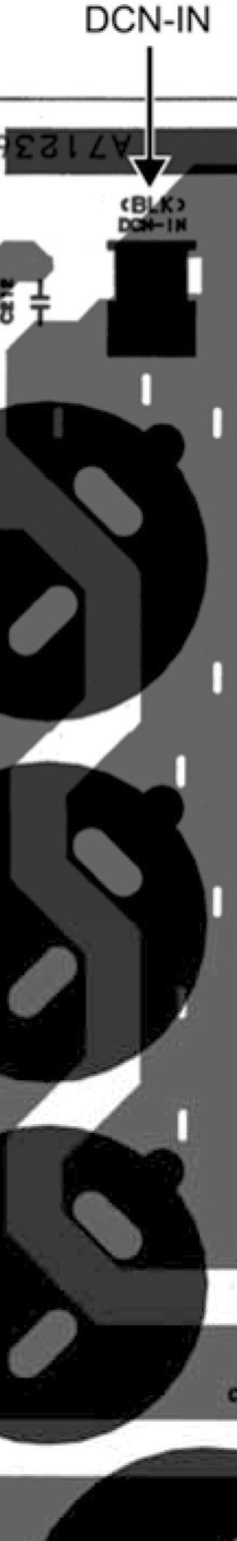
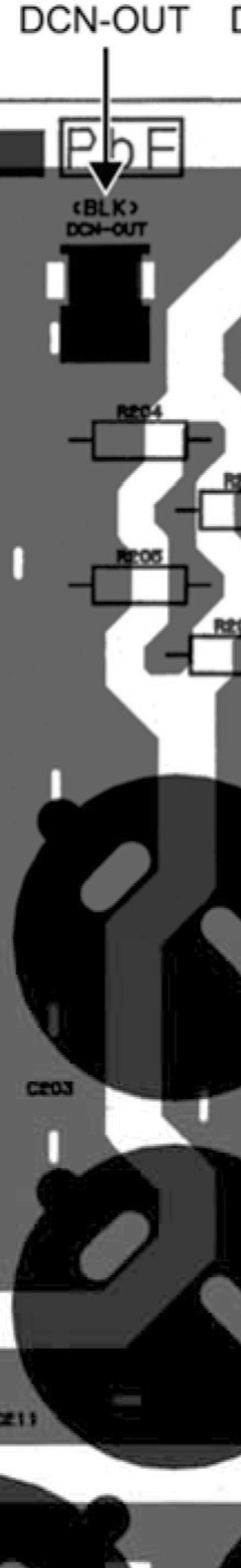
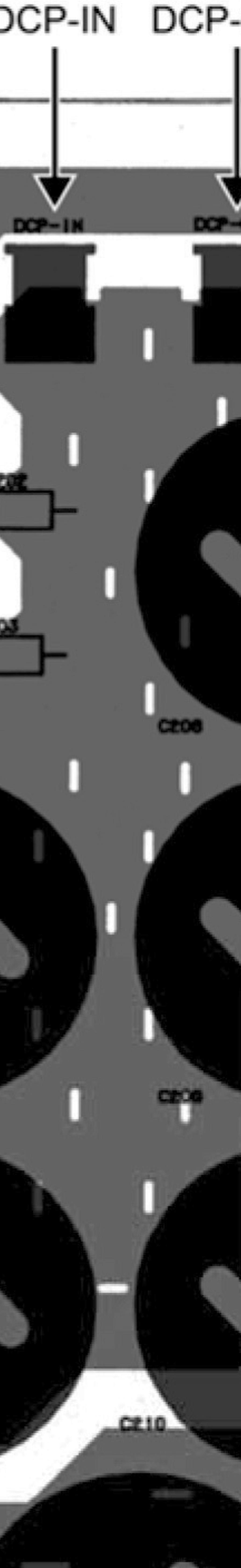
40 0.2 Outdoor Unit Main Printed Circuit Board WH-UX09FE5 WH-UX2FE5 DCN2 DCP CN-FM2 CN-FM CN-WHT AC-L DCN COM3 AC-WHT02 AC-C AC-BLK02 CN-V CN-HT CN-HT2 CN-HOT CN-PSW CN-RY CN-TANK CN-HPS CN-TH3 CN-TH CN-TH2 CN-EV2 CN-DIS CN-EV 40
41 WH-UD2FE5 WH-UD6FE5 DCN2 DCP CN-FM2 CN-FM CN-WHT AC-L DCN COM3 AC-WHT02 AC-C AC-BLK02 CN-V AC-BLK0 CN-HT CN-HT2 CN-HOT CN-PSW CN-RY CN-TANK CN-HPS CN-TH3 CN-TH CN-TH2 CN-DIS CN-EV 4
42 ise Filter Printed Circuit Board CN-ACL AC-BLK CN-BLK CN-ACN CN-WHT FG FG Capacitor Printed Circuit Board WH-UX09FE5 WH-UX2FE5 DCN-IN DCN-OUT DCP-IN AC-C 42


43 WH-UD D2FE5 WH-UD6 6FE5 43
44 . Field. i ii Installation Instruction Supply Accessories Part Qty. 2-way Valve Kit Room Thermostat It is recommended to purchase the field supply accessories from the specific maker whom listed in above table.. Indoor Unit Electromotoric Actuator 2-port Valve Analog Type Programmable Type Model SFA2/8 VVI46/25 RAA20 REV200 Specifications AC230V -- AC230V Maker Siemens Siemens Siemens... Select the Best Location Install the Tank Unit in indoors with frost free weather proof location only. Must install on a flat horizontal and solid hard surface. There should not be any heat source or steam near the Tank Unit. A place wheree air circulation in the room is good. A place wheree drainage can be easily done (e.g. Utility room). A place wheree Tank Unit s operation noise will not cause discomfort to the user. A place wheree Tank Unit is far from door way. A place wheree accessible for maintenance. Ensure to keep minimum distance of spaces as illustrated below from wall, ceiling, or other obstacles. A place wheree flammable gas leaking might not occur. Secure the Tank Unit to prevent it being knocked over accidentally or during earthquakes. o If it transported in vertical, use the hand holes on sides, slide and move to the desired location. Fix the Adjustable Feet, if the Tank unit installed on an uneven surface. Hold Hold arrow section Hold to slideandmove..2 To Drill a Hole in the Wall and Install a Sleevee of Piping Make a Ø70 mm through hole. 2 Insert the piping sleeve to the hole. 3 Fix the bushing b to the sleeve. 4 Cut the sleeve until it extrudes about 5 mm from thee wall..... Required space for installation ( Unit : mm) Min. 00 Min. 300 Min. 00 CAUTION When the wall is hollow, please be sure to use the sleeve for tube assembly to prevent dangers caused by mice biting the connection cable. 5 Finish by sealing thee sleeve with putty or caulkingg compound at the final stage. Min. 700 Min. 00 Indoor Wall Outdoor 5 mm....2 Transport and Handling Be careful during transporting the unit so that it is not damaged by impact. Only remove the packaging material once it has reached it is desired installation location. It may need three or more people to carry out the installation work. The weight of Tank Unit might cause injury if carried by one person. The Tank Unit can be transported either in vertical or horizontal. o If it transported in horizontal, make sure Front of packaging material (printed with FRONT ) must facing upwards. Sleeve for tube assembly ø70 mm through hole Approx. 5-7 mm Bushing for tube assemblys Putty or caulking compound 44
45 ..3 Piping Installation..3. Air-to-Water Heatpump Outdoor Unit..3.2 Pressure Relief Valve Drainage Tank Water Discharge Tundish This section is for authorized and licensedd electrician/water system installer only. Work behind the frontt plate secured by screws must only be carried out under supervision of qualified contractor, installation engineer or service person. Open and Close Top Front Plate Do not open or close the top front f cabinet by excessive force. 2 Follow below illustrations to open / close the Top Front Plate. To Open To Close Typical Piping Installation Access to Internal Components Top Front Plate Open click 3X (screw) 2X (screw) Pressure Relief Valve WARNING CAUTION 2-Way Valve click Lever Arm Hook Slot Expansion Vessel Close Fan Coil Unit Radiator / Floor Heater Check Shut Valve Off Valve When open or close the Top Front Plate, make sure it is securely holdinposition.else, it may falll and injures the fingers or palms. Open or close the Bottom Front Plate carefully. The heavy Bottom Front Plate may injures the fingers. Faucet Tab / Shower Main Water Supply Pressure Reducing Valve Hold in position Open and a Close Bottom Frontt Panel Must open the Top Front Plate before access Bottom Front Plate. 2 Remove the 5 mounting screws of Bottom Front Plate. 3 Slide it upwardss to unhook the t Bottom Front Plate hooks andd slots. 4 Reverse above steps ~3 for close it Refrigerant Piping Installation This Tank Unit U is designed for combination with Panasonic Air-to-Water A Heat Pump Outdoor Unit. If Outdoor Unit from otherr manufacturer are being used in combination with Panasonic Tank Unit, optimum operation and reliability of the system is not guaranteed. Thus warranty cannot be given in such case. Connect Tank Unit to Air-to-Water correct piping Heatpump Outdoor Unit with size. Model M Pipingg size (Torque) Tank Unit Outdoor Uniit Gas Liquid UX09*E5* / ADC26*E5* UX2*E5* / ø5.88mm (5/8") Ø9.52mmm (3/8") UD2*E5* / [65 N m] ] [42 N m] UD6*E5* CAUTION Do not overtighten, overtiightening may cause c gas leakage. 2 Please make flare after inserting flare nut (located at joint portion of tube assembly) onto the copper pipe. (In case of using long piping) 3 Do not use pipee wrench to open refrigerant piping. Flare nutt may be broken and cause leakage. Use proper spanner or ring wrench. 4 Connect the piping: o Align the centre of piping and sufficiently tighten the flare nut with fingers. o Further tighten the flare nut with torque wrench in specified torque as stated in the table Cutting and Flaring the Pipingg Please cut usingg pipe cutterr and then remove the burrs. 2 Remove the burrs by using reamer. If burrs is not removed, gas leakage may be caused. Turn the piping end down to avoid the metal powder enteringg the pipe. 3 Please make flare after inserting the flare nut ontoo the copperr pipes. Pipe Handle Reamer Bar Yoke Bar 0 0.5mm Core. Tocut Point down Clamp handle Red arrow mark 2. To remove burrs 3. To flare Improper flaring Inclined Surface Cracked Uneven damaged thickness When properly flared, the internal surface of the flare will evenly shine and be of even thickness. Since the flare part comes into contact with the connections, carefully check the flare finish. Copper pipe 45
46 Water Piping Installation Please engage a licensed water circuitt installer to install this water circuit. This water circuit must comply with relevant European and national regulations (including EN6770), and local building regulation codes. The minimum requirement of water in the t system is 50 litres. If this value could not be achieved, please install additional buffer tank (field supply). Ensure the components installed in the water circuit could withstand water pressure during operation. Do not use worn out tube. Do not apply excessive force to pipes that may damage the pipes. Choose proper sealer which can withstand the pressures and temperatures of the system. Make sure to use two spanners to tighten the connection. Further tighten the nuts with torque wrench in specified torque as stated in the table. Cover the pipe end to prevent dirt and dust when inserting it through a wall. Choose proper sealer which can withstand the pressures and temperatures of the system. If non-brass metallic piping is used for installation, make sure to insulate the pipes to prevent galvanic corrosion. Use correct nut for all Tank Unit tube connections and clean all tubes with tap water before installation. See Tube Position Diagram for detail. Tube Connector Nut Size Torque g & h RP ¼" 7.6 N m i & j RP ¾" N m CAUTION Do not overtighten,, overtightening may cause water leakage. Make sure to insulate the water circuit pipes to prevent reduction of heating capacity. After installation, check the water leakage condition in connection area during test run. Failure to connect the tube appropriately might cause the Tank Unit malfunction. Protection From Frost: If the Tank Unit is being exposed to frost while power supply failure or pump operating failure, drain the system. When water is idle inside the system, freezing up is very likely to happen which could damage the system. Make sure the power supply is turned off before draining. Heater Assembly may be damaged under dry heating. Corrosion Resistance: Duplex stainless steel is naturally corrosion resistant to mains water supply. specific maintenance is required to maintain this resistance. However, please note that Tank Unit iss not guaranteed for use with a private water supply. It is recommended to use a tray (field supply) to collect water from the Tank Unit if water leakage occur. (A) Model Tank Unit Outdoor O Unit UX09*E5* UX2*E5* ADC26*E5* UD2*E5* UD6*E5* (B) (C) Space Heating/Coolingg Pipework Connect Tank Unit Tubee Connector g to outlet connector of Panel/Floorr heater. Connect Tank Unit Tubee Connector h to inlet connector of Panel/Floorr heater. Failure to connect the tube appropriately might cause the Tank Unit malfunction. Refer beloww table for thee rated flow rate r of each particular Outdoor Unit. Rated Flow Rate (L/min) Cool Heat Domestic Hot H Water Tank Pipework It s strongly recommended to install an expansion vessel (field supply) in the Domestic Hot Water Tank circuit.. Refer Typical Piping Installation section to locate the expansion vessel. o Recommended pre-charge pressure of the expansion vessel (field supply) = 0.35MPa (3.5 bars) In high water pressure or water supply is above 500kPa, please install the Pressure Reducing Valve for water supply. If the pressure higher than that, it mightt damage thee Tank Unit. A Pressure Reducing Valve (field supply) and Pressure Relief Valve (field supply) with below specificationn is strongly advised to be installed along the line of the tubee connector j of Tank Unit. Refer Typical T Piping Installationn section to locate both of o these valves. Recommended Pressuree Reducing Valve specifications: o Set pressure: 0.35 MPa (3.5 bars) Recommended Pressuree Relief Valve specifications: o Set pressure:.0 MPa (0.0 bars) Must connect a faucet too Tank Unit Tube Connector i and main water supply, in order to supply water with appropriate temperature for shower or tap usage. Failure to do so might cause scalding. Failure to connect the tube appropriately might causing the Tank Unit malfunction. Pressure Relief Valve Drainage Pipework Connect a drain d hose with inner diameter of 5 mm to Pressure Relief Valve Drainage. The hose must be installed in a continuously downward direction d and left open to the frost-freee atmosphere. If drain hosee is long, usee a metal support fixture along the way to eliminate the wavy pattern of drain tube. The water may m drip fromm this discharge hose. Therefore must m guide thee hose without close or block the outlet of the hose. 46
47 Do not insert this hose into sewage hose or cleaning hose that may generate ammonia gas, sulphuric gas etc. If necessary, use a hose clamp to tighten the hose at drain hose connector to prevent it from leaking. Guide the drain hose to outdoor as illustrated at the right figure. Drain hose connector Drain hose Illustration of how to fix drain hose to Tank Unit (D) Domestic Hot Water Tank Discharge Pipework Use R½" male connector for Domestic Hot Water Tank Discharge connection. Piping must to be installed in a continuously downwardd direction and in a frost-free environment. Discharge pipes must be visible and away fromm electrical components. Guide the drain hose to outdoor as illustrated at the below figure. It is recommended to fit a tundish into this pipework. Tundish should be visible and positioned away from frost environment and electrical components. Discharge below fixed grating Fixed grating Trapped gulley Possible wall Illustration of guide drain hose to outdoor (E) Drain Elbow and Hose Installation Fix the Drain Elbow w and Packing to the bottom of Drain Water W Hole. Use inner diameter 7 mm drain hose in the market. This hose must to be installed in a continuously downward direction and in a frost-free environment. Guides this hose outlet to outdoor only. Do not insert this hose into sewage or drain pipe that may generate ammonia gas, sulphuric gas, etc. If necessary, use hose clamp to further tighten the hose at drain hose connector to prevent leakage. Water will w drip from this hose, therefore the outlet of this hose h must bee installed in an area where the outlet cannot become blocked. Packing 3 Drain Elbow 2..4 Connect the Cable to Tank Unitt WARNING This section is for authorized and licensed electrician only. Work behind the Control Boardd Cover securedd by screws must only be carried out under supervision of qualified contractor, installation engineer r or service person...4. Fixing of Power Supply Cable and Connecting Cable C Connecting cable between Tank Unit and Outdoor Unit shall be approved polychloroprene sheathed flexible cord, type designation IEC 57 or heavier cord. See below table for cablee size requirement. Tank Unit ADC26* *E5* Model Outdoor Unit UX09*E5* / UX2*E5* / UD2*E5* / UD6*E5* Connecting Cable Size 4 x 4.0 mm 2 o o Ensure the colour of wires of Outdoorr Unit and the terminal no. are the same to the Tank Unit respectively. Earth wire shall be longer than the other wires as shown in thee figure for the electrical safety in case of the slipping out of the cord from the Holder (Clamper). 47
48 2 An isolating device must be connected to the power supply cable. o Isolating device (disconnecting means) should have minimum 3.0 mm contact gap. o Connect the approved polychloroprene sheathed power supply cord c and power supply 2 cord and type designation IEC 57 or heavier cordd to the terminal board, and to the other end of the cord to isolating device (Disconnecting means). See below table for cable size requirement. Model Tank Unit Outdoor Unit UX09*E5* * / UX2*E5* * / ADC26*E5* UD2*E5* * / UD6*E5* Power Supply Cord 2 Cable Size 3 x 4.0 mm 2 3 x 4.0 mm 2 Isolating Devices Recommended RCD 30A 40mA, 2P, typee A 30A 40mA, 2P, type AC 3 To avoid the cable and cord being damaged byy sharp edges, the cable and cord must be passed through a bushing (located at the bottom of Control Board) before terminal board. The bushing must be used and must not be removed. Terminals on the Outdoor Unit Colour of wires (Connecting cables) 2 3 RCCB/ELCB Terminal Board Terminals on the Tank unit (Power Supply Cord) Terminals on the isolating devices from power supply (Disconnecting means) 2 3 Tank Unit/ / Outdoor Unit connectionn L N L N Power Supply L L N N Power Supply 2 Connecting Cable * * Holder (Clamper) Bushing Power Supply Cable Terminal screw M4 M5 Tightening torque N cm {kgf cm} 57~96 {6~20} 96~245 {20~25) * - Earth wire must be longer than other cables for safety reasons Connecting with external devicee (optional) All connections shall follow to the local national wiring standard. 2 It is strongly recommended to use manufacturer-recommended parts and accessories for installation. 3 Two-way Valve shall be spring and electronic type, refer to Field Supply Accessories table for details. Valve cable shall be (3 x min 0.5 mm 2 ), of type designation IEC 57 or heavier, h or similarly double insulationn sheathed cable. o * note: - Two-way Valve shall be CE marking compliance component. - Maximumm load for the valve is 9.8VA. 4 Room Thermostat cable must be ( 4 or 3 x min 0.5 mm 2 ), double insulation layer of PVC-sheathed or rubber- sheathed cable. 5 External Controller shall be connected to -pole switch with min 3.0mmm contact gap. (connection refer to Diagram 4.). Its cable must be (2 x min 0.5 mm 2 ), double insulation layer of PVC-sheathed or rubberand 5. sheathed cable. o * note: - When making such connection, kindly removee the jumper between terminal no. 4 - Switch used shall be CE compliance component. - Maximumm operating current shall be less than 3A rms. Terminals Lead wire cord 2 3 N OPEN CLOSE L HEAT COOL N Remove this jumper if External Controller (Optional) is connected to the Tank Unit External Controller Terminal 4 5 Switch (ON/OFF) Two-way Valve Cable External Controller Cable Room Thermostat Cable Diagram 4. : External Controller connecting diagram 48
49 ..4.3 Wire Stripping and Connecting Requirement 0 ± mm Wire stripping loose strand when insert Indoor/outdoor connecting terminal board 5mm or more (gap between wires) Conductor fully insert ACCEPT Conductor over insert PROHIBITED Conductor not fully insert PROHIBITED..4.4 Connecting Requirement For Tank Unit with UX09* E5* / UX2* E5*/ UD2*E5* / UD6*E5* This equipment s Power Supply complies with IEC provided that the short circuit power S sc is greater than or equal to 800kW at the interface point between the user s supply and the public system. It is the responsibility of the installer or user of the equipment to ensure, by consultation with the distribution network operator if necessary, that the equipment is connected only to a supplyy with a short circuit power S sc greater than or equal to 800kW. The equipment s Power Supply shall be connected to a suitable supply network, having services current capacity 00A per phase. Please liaise with supply authority that the service current capacity at the interface point is sufficient for the installation of the equipment. The equipment s Power Supply 2 complies with IEC/EN The equipment s Power Supply 2 shall be connected to suitable supplyy network, with the following maximumm permissible system impedance Zmax at the interface of the point: 0.357Ω. Please liaise with supply authority to ensure that the Power Supply 2 iss connected only to a supply of that impedance or less...5 Charging and Discharging the Water Make sure all the piping installations are properly done before carry out below steps...5. Charge the Water For Domestic Hot Water Tank Set the Domestic Hot Water Tank Discharge Valve to CLOSE. CLOSE Domestic Hot Water Tank Discharge Valve g 2 Set all Tap / Shower OPEN. 3 Start filling water to the Domestic Hot Water Tank via Tube Connector i. After 20~40min, water should flow out fromm Tap / Shower. Else, please contact your local authorized dealer. 4 Check and make sure no water leaking at the tube connecting points. For Space Heating / Cooling Turn the plug on the Air Purge Valve outlet anticlockwise by one completee turn from fully closed position. S O OPEN 2 Set the Pressure Relief Valve level DOWN. Pressure relief valve d Lever Turn up Pressure relief valve d 3 Start filling water (with pressure more than 0. MPa ( bar) )) to the Space Heating / Cooling circuit via Tube Connector g. Stop filling water if the free water flow throughh Pressure Relief Valve Drainage. 4 Turn ON the Tank Unit and make sure Water Pump is running. 5 Check and make sure no water leaking at the tubee connectingg points Discharge the Water For Domestic Hot Water Tank Turn OFF power supply. 2 Set the Domestic Hot Waterr Tank Discharge Valve to OPEN. 3 Open Tap / Shower to allow air inlet. 4 After discharge,, set Hot Water Tank Discharge Valvee to CLOSE. Plug (turn anticlockwise by one complete turn) Air purge valve c 49
50 .2 Outdoor Unit Attached accessories Optional Accessory. Accessories part Drain elbow Qty.. 3 Accessories part Protective bushing Qty Base Pan Heater CZ-NE3P Accessories part Qty. 2 Rubber cap 8 It isstronglyrecommended to install a Base Pan Heater (optional) if the outdoor unit is install in cold climate area. Refer the Base Pan Heater (optional) installation instruction for details of installation..2.. Select the Best Location If an awning is built over the unit to prevent direct sunlight or rain, be careful that heat radiation from the condenser is not obstructed. Avoid installations in areas where the ambient temperature may drop beloww -20 C. Keep the spaces indicatedd by arrows from f wall, ceiling, fence or other obstacles. Do not place any obstacles which may cause a short circuit of the discharged air. If outdoor unit t installed near sea, region with high content of sulphur or oily location (e.g. machinery oil, etc), it lifespan maybe shorten. When installing the product in a place where it will be affected by typhoon or strong wind such as wind blowing between buildings, including the rooftop of a building and a place wheree there is no building in surroundings, fix the product with an overturn prevention wire, etc. (Overturn preventionn fitting model number: K-KYZP5C) If piping length is over 0 m, additional refrigerant should be added as shown in the table. Model UX09*E5*, UX2*E5* *, UD2*E5*, UD6*E5*, UX09*E8*, UX2*E8* *, UX6*E8*, UD09*E8*, UD2*E8*, UD6*E8* Piping size Gas Liquid ø5.88mmm (5/8") Ø9.52mm (3/8") Example: If piping length is 30m, the quantity of additional refrigerant should be 000g. [( 30-0)m x 500 g/m = 000g].2..2 Install the Outdoor Unit Rated Lengthh (m) 5 Max. Elevation (m) Installation Diagram It is advisable to avoid more than 2 blockage directions. For better ventilation & multiple-outdoor installation, please consult authorized dealer/specialist. This illustration is for explanation purposes only. 20 Min. M Piping Length L (m) 3 Max. Piping Length (m) 30 Additional Refrigerant (g/m) 50 Vinyl tape (Wide) 00mm or more 000mm or more 00mm or more 300mm or more Saddle Indoor/Outdoor connecting cable - For UX09*E5*, UX2*E5*, UD2*E5*, UD6*E5* use 4-CORE WIRE min4.0mm 2 - For UX09*E8*, UX2*E8*, UX6*E8*, UD09*E8*, UD2*E8*, UD6*E8* * use 6-CORE WIRE min.5mm 2 Type designation IEC 57 or heavier cord ø9.52mm (3/8") Liquid refrigerant piping ø5.88mm (5/8") Gas refrigerant piping [ Check that the cables do touch the compressor, etc. not] 50
51 F C A B (Anchor pitch) E Model A B C D E F D (Anchor pitch) UX09*E5*, UX2*E5*, U UD2*E5*, UD6*E5*, U UX09*E8*, UX2*E8*, U UX6*E8*, UD09*E8*, U UD2*E8*, UD6*E8* U (Unit : mm) After selecting the best location, start installation according to Installation Diagram.. Fix the unit on concrete or rigid frame firmly and horizontally by bolt nut (ø0 mm). 2 When installing at roof, pleasee consider strong wind and earthquake. Please fasten the installation stand firmly with bolt or nails Disposal of Outdoor Unit Drain Water When a Drain elbow is used, please ensure too follow below: o the unit should be placed on a stand whichh is taller than 50 mm. o cover the ø20mm holes with Rubber cap (refer to illustration below). o use a tray (field supply) when necessary too dispose the outdoor unit drain water. If the unit is used in an area wheree temperature falls below 0 C for 2 or 3 consecutive days, it is recommended not to use the Drain elbow and Rubber cap, for the drain water freezess and the fann will not rotate. Drain elbow.2.3 Connecting the Piping Rubber cap 2 x 8 CAUTION Do not n over tighten, over tighteningg may cause gas leakage. Model UX09*E5*, UX2*E5*, UD2*E5*, UD6*E5*, UX09*E8*, UX2*E8*, UX6*E8*, UD09*E8*, UD2*E8*, UD6*E8*.2.3. Connecting the Piping to Outdoor Unit Decide piping length and then cut by using pipe cutter. Remove burrs from cut edge. Make flare after nserting the flare nut (locate at valve) onto the copper pipe. Align center of piping to valves and then tighten with torque wrench to the specified torque as stated in the table. Local pipes can project in any of four directions. Make holes in the pipe panels for the pipes to pass through. Be sure to install the pipe panels to t prevent rain from getting inside the outdoor unit. [Removing the servicee panel]. () Remove the three mounting screws. (2) Slide the service panel downward to release the pawls. After this, pulll the service panel toward you to remove it. Gas G ø5.88mm (5/8") [65 N m] Mounting screws Piping size (Torque) Liquid Ø9.52mm (3/8") [42 N m] Service panel Rear direction Rear pipe panel Side panel Forward direction Front pipe panel Downward direction 5
52 Be sure to use two spanners to tighten. (If the nuts are overtightened, it may cause the flares to break or leak.) Close the tube joining area with putty heat insulator (local supply) without any gap as shown in right figure. (To prevent insects or small animal entering.) Do not attach the spanners here Putty or Heat insulator (local supply) Cutting and Flaring the Piping Please cut using pipe cutter and then remove the burrs. 2 Remove the burrs by using reamer. If burrs is not removed, gas leakage may be caused. Turn the piping end down to avoid the metal powder entering the pipe. 3 Please make flare after inserting the flare nut onto the copper pipes. Pipe Handle Reamer Bar Yoke Bar Core Point down Clamp handle Red arrow mark. To cut 2. To remove burrs 3. To flare 0 0.5mm Copper pipe Improper flaring Inclined Surface Cracked Uneven damaged thickness When properly flared, the internal surface of the flare will evenly shine andbeofeventhickness.sincethe flare part comes into contact with the connections, carefully check the flare finish..2.4 Evacuation of the Equipment WHEN INSTALLING AN AIR-TO-WATER HEAT PUMP, BE SURE TO EVACUATE THE AIR INSIDE THE UNIT AND PIPES in the following procedure. Indoor unit Liquid side Two-way valve Outdoor unit Close Gas side Vacuum pump adaptor Three-way valve Close Vacuum pump CLOSE OPEN Connect a charging hose with a push pin to the Low side of a charging set and the service port of the 3-way valve. o Be sure to connect the end of the charging hose with the push pin to the service port. 2 Connect the center hose of the charging set to a vacuum pump with check valve, or vacuum pump and vacuum pump adaptor. 3 Turn on the power switch of the vacuum pump and make sure that the needle in the gauge moves from 0 cmhg (0 MPa) to 76 cmhg ( 0. MPa). Then evacuate the air approximately ten minutes. 4 Close the Low side valve of the charging set and turn off the vacuum pump. Make sure that the needle in the gauge does not move after approximately five minutes. te : BE SURE TO FOLLOW THIS PROCEDURE IN ORDER TO AVOID REFRIGERANT GAS LEAKAGE. 5 Disconnect the charging hose from the vacuum pump and from the service port of the 3-way valve. 6 Tighten the service port caps of the 3-way valve at a torque of 8 N m with a torque wrench. 7 Remove the valve caps of both of the 2-way valve and 3-way valve. Position both of the valves to OPEN using a hexagonal wrench (4 mm). 8 Mount valve caps onto the 2-way valve and the 3-way valve. o Be sure to check for gas leakage. 52
53 CAUTION If gauge needle does not move from 0 cmhg (0 MPa) to 76 cmhg ( 0. MPa), in step 3 above take the following measure:. If the leak stops when the piping connections are tightened further, continue working from step If the leak does not stop when the connections are retightened, repair location of leak. 3. Do not release refrigerant during piping work for installation and reinstallation. Take care of the liquid refrigerant, it may cause frostbite..2.5 Connect the Cable to the Outdoor Unit (FOR DETAIL REFER TO WIRING DIAGRAM AT UNIT) Remove the control board cover from the unit by loosening the screw. 2 Connecting cable between indoor unit and outdoor unit shall be approved polychloroprene sheathed flexible cable (see below table), type designation IEC 57 or heavier cable. 3 Secure the cable onto the control board with the holder (clamper). 4 Attach the control board cover back to the original position with screw. WARNING This equipment must be properly earthed. Select required direction and apply protective bushing provided in accessories to protect cables from sharp edges. Once all wiring work has been completed, tie the cable and cord together with the binding strap so that they do not touch other parts such as the compressor and bare copper pipes. Models UX09*E5*/UX2*E5*/ UD2*E5*/UD6*E5* Flexible cable specification 4xmin4.0mm 2 Outdoor Unit Indoor/outdoor unit terminal board Terminals on the indoor unit 2 3 Colour of wires Terminals on the outdoor unit 2 3 Earth Wire must be longer than others cables for safety reason. Cord clamp Banding strap (Field Supply) Connecting cable (refer below diagram for its guiding) Models UX09*E8*, UX2*E8*, UX6*E8*, UD09*E8*, UD2*E8*, UD6*E8* Flexible cable specification 6 x min.5 mm 2 Protective bushing 3 Selection of direction Terminals on the indoor unit Colour of wires Terminals on the outdoor unit Apply cut DETAIL OF CONNECTING CABLE GUIDING Earth Wire must be longer than others cables for safety reason. CAUTION For three phase model never operate the unit by pressing the electromagnetic switch. Never correct the phase by switching over any of the wires inside the unit. 53
54 Wire Stripping and Connecting Requirement 0 ± mm Wire stripping Indoor/outdoor connecting terminal board Conductor fully insert Conductor over insert Conductor not fully insert loose strand when insert 5mmormore (gap between wires) ACCEPT PROHIBITED PROHIBIT TED.2..6 Pipe Insulation Please carry out insulation at pipe connection portion as mentioned in Indoor/OutdoI oor Unit Installation Diagram. Please wrap the insulated piping endd to prevent water from going inside the piping. 2 If drain hose or connecting piping is i in the roomm (where dew may form), please increase the insulation by using POLY-E FOAM with thickness 6 mm or above. 54
55 2. Operation and Control 2. Basic Function Inverter control, which equipped with a microcomputer in determining the most m suitablee operating mode as time passes, automatically adjusts output power for maximum comfort always. In order to achieve the suitable operating mode, the microcomputerr maintains the set temperature by measuring the temperaturee of the environment and performing temperature shifting. The compressor at outdoor unit is operating following the frequency instructed by the microcomputer at indoor unit that judging j the condition according to internal water setting temperature and water outlet temperature. 2.. Internal Water Setting Temperature Once the operation starts, control panel setting temperature will be taken as a base valuee for temperature shifting processes. These shifting processes are depending on the Air-to-Water Heat pump settings and the operation environment. The final shifted value will be used as internal water setting temperature and it is updated continuously whenever the electrical power is supplied to the unit Heating Operation Thermostat Control Compressor is OFF when Water Outlet Temperature Internal Water Setting S Temperature > 2 C for continuously 3 minutes. Compressor is ON after waiting for 3 minutes, if the Water Outlet Temperature Water Inlet Temperature (temperature at thermostat OFF is triggered) < <-3 C Thermostat Control (Outdoor Ambient Temperature) Stops provide heating to room side during high outdoor ambient condition. Control content: Heating operation and water pumpp will turn OFF when outdoor ambient temperature > outdoor thermo off temperature + 3 C. (Outdoor thermo off set temperature is set by control panel. Thermo off set temperature is between 5 C ~ 35 C) Heating operation will resume when Outdoor ambient temperature < Outdoor O thermo OFF set temperature t + C Heat Mode Operation Operation of heat pump provide heating capacity to room side by hot water through heating panel, floor heating or fan coil unit. 3 ways valve control: o 3 ways valve switch and fix to heatingg side. 2 Heat pump operates follow normal heatingg operation. 3 Back up heater operate follow normal operation. 4 2 ways valve control: o 2 ways valve opens. 55
56 Heat Mode Operation Time Chart Exp: 3waysvalve On Off 2waysvalve Open Close Heat Pump On Off Backup Heater On Off ID Water Pump On Off Water Outlet Temp 53 C 53 C 57 C 45 C 47 C 50 Backup Heater Startup Timer Timer for backup heater to on back from previous off Backup Heater Startup Timer Tank Temp. Mode On Heater On Heater Off Heater On Heater Off HeatPump Thermo Off HeatPump Thermo On 56
57 2..3 Cooling Operation Thermostat controll Compressor is OFF when Water Outlet Temperature Internal Water Setting S Temperature > -.5 C for continuously 3 minutes. Compressor is ON after waiting for 3 minutes, if the Water Outlet Temperature Water Inlet Temperature (temperature at thermostat OFF is triggered) > >3 C Cool Mode Operation 3 ways valve control: o 3 ways valve switch and fix to coolingg side. 2 Heat pump operates follow normal coolingg operation. 3 Back up heater DOES NOT operate duringg cool mode. 4 Solar 3 way valve operates follow solar operation specification. 5 2 ways valve control: o 2 ways valve is closed. Cool Mode Operation Time Chart 3 ways valve On Off 2 ways valve Open Close Heat Pump On Off Backup Heater On Off Water Outlet Temp 6 C 8.5 C Mode On HeatPump Thermo Off HeatPu ump Thermo On 57
58 2..4 Auto Mode Operation Heat To Cool Setting Temp. Outdoor Ambient COOL MODE HEAT MODE Cool To Heat Setting Temp. Control details: o To enable the unit to operate either heat or cool mode automatically, heat to cool set temperature and cool to heat set temperature can be set by control panel. o Automatic operation is judged based on control panel setting temperature and outdoor ambient temperature. * Minimum setting of heat to cool set temperature is C higher than cool to heat set temperature. Judgement control: o If outdoor ambient temperature < Heat to Cool Set Temperature, unit will operate in Heat Mode or else the unit will operate in Cool Mode. o If current operation is Cool mode, outdoor ambient temperature > Cool to Heat Temperature, unit will maintain Cool mode operation or else the unit will operate Heat mode. o If current operation is Heat mode, outdoor ambient temperature >Heat to Cool Temperature, unit will maintain Heat mode operation or else the unit will operate Cool mode. o Every 60 minutes the outdoor ambient temperature is judged. o When Auto + Tank mode is selected, operation mode switching is judged by both outdoor ambient temperature and indoor air temperature. 58
59 2..5 Tank Mode Operation Control contents: a. 3 ways valve direction o 3 ways valve switch to tank side during TANK THERMO ON condition. Switch 3 ways valve to room side when tank achieve TANK THERMO OFF temperature. b. Heat Pump Thermostat characteristic o Tank water set temperature = tank set temperature or 5 C whichever lower. o Heat pump Water Outlet set temperature is set to 57 C when Outdoor < 5 C and 59 C when Outdoor 5 C. Characteristic of heat pump thermo ON/OFF under Tank Mode condition: Water Outlet Thermo Condition o Heat pump THERMO OFF TEMP:. Water outlet temperature > Heat Pump Water Outlet Set Temp for continuously 90 seconds, heat pump OFF but water pump continues ON. o o o Heat pump THERMO ON TEMP:. Heat pump THERMO ON TEMP = Water inlet during thermo OFF time + [-3 C]. 2. When water outlet temperature is less than Heat pump THERMO ON TEMP, heat pump ON. Water Inlet Thermo Condition Heat pump THERMO OFF TEMP:. Water inlet temperature is more than 55 C when Outdoor < 5 C and 57 C when Outdoor 5 C for continuously 30 seconds, heat pump OFF, water pump will continue ON. Heat pump THERMO ON TEMP when Water inlet < water inlet THERMO OFF temperature. Tank Thermo ON/OFF for HEAT Pump Operation: When tank temperature achieve Heat Pump OFF condition, refer below condition: Condition : When Backup Heater for Tank Select USE from remote controller. o Heat Pump Turn OFF, Water pump continue ON and Backup Heater will continue boil up the tank if tank temperature below Tank Heater Thermo ON condition. 3 ways valve will only switch to room side after heater boil tank to Tank Heater Thermo OFF condition. o o o Condition 2: When Backup Heater for Tank Select NO USE from remote controller. Heat Pump Turn OFF, water pump turn OFF, Backup heater OFF and 3 ways valve switch to room side. When tank temperature achieve Heat Pump ON condition, Water Pump ON, Heat Pump ON and Backup Heater turn OFF Heat Pump OFF Condition at Tank Mode:. Tank Temperature > Tank Water Set Temperature + [0 C] continuously for 0 seconds after heat pump Thermo OFF due to water thermo, (Heat Pump turn OFF but water pump continue ON and Backup Heater Turn ON to boil tank to achieve Tank Set Temperature), OR 2. Tank Temperature > Tank Set TEMPERATURE + [2 C] for continuously 0 seconds (Heat Pump OFF, Water pump OFF, Backup Heater OFF and 3-ways valve switch to room side) Heat Pump ON Condition at Tank Mode:. Tank Temperature < Tank Water Set Temperature + [-8 C]. (Water Pump Turn ON OR Continue ON, Heat Pump ON and 3-ways valve switch to tank side or maintain at tank side) c. Backup Heater Control o Backup Heater Turn ON condition:. Tank Temperature < Tank Set Temperature + [0 C] AND 2. Heat Pump Thermo OFF AND minutes from previous heater OFF. AND 4. Backup Heater for Tank Select USE from remote controller. 59
60 o Backup Heater Turn OFF condition:. Tank Temperature > Tank Set Temperature + [0 C] for continuously 5 seconds. OR 2. Heat Pump Thermo ON OR 3. Mode Change or Operation OFF by remote controller. * Turn ON All heater element according to the maximum heater selection when heater is request to ON by remote controller. d. 2 way valve control: o 2 ways valve close. Tank mode Tank set Temp. = 65 C 3wayvalve on off Heat Pump on off Backup Heater on off ID Water Pump on off Tank side Tank Thermo OFF 65 C Tank Temp. 5 C 58 C 48 C Water Outlet Temp. 57 C 57 C 57 C 60
61 2..6 Heat + Tank Mode Operation. 3 ways valve control: o 3 ways valve switch to room side during room heat-up interval, and switch to tank side during tank heat-up interval. Both modes will switch alternately. Tank mode is the initial running mode of this heat + tank mode (heating no priority). 2. Heat pump operation control: o During room heat-up interval Follow normal heating operation. Switch to tank heat-up interval when External Room Thermo OFF AND Tank temperature < TANK THERMO ON TEMP (End Room Interval) OR During Room heat-up interval, always detect tank temperature and switch to tank heat-up interval when tank temperature < TANK THERMO ON TEMP (End Room Interval) * When heating operation at room side is less than 30 minutes and switch to tank side for consecutive 3 times, heat pump will be forced to operate heat mode at room side and complete the room heat up interval regardless of the tank temperature. After complete the heat interval heat pump will only switch to tank side. o During tank heat-up interval Tank Water Set Temperature = tank set temperature or 5 C whichever lower. Heat Pump Water Outlet set temperature is set to 57 C when Outdoor < 5 C and 59 C when Outdoor 5 C. Characteristic of heat pump thermo ON/OFF under tank side condition: Water Outlet Thermo Condition o Heat pump THERMO OFF TEMP:. Water outlet temperature > Heat Pump Water Outlet Set Temp for continuously 90 seconds, heat pump OFF but water pump continue ON. o THERMO ON TEMP:. THERMO ON TEMP = Water inlet when heat pump THERMO OFF + [-3 C]. 2. If water outlet temperature < THERMO ON TEMP AND External Room Thermo OFF, heat pump ON. Water Inlet Thermo Condition o Heat pump THERMO OFF TEMP. Water inlet temperature is more than 55 C when Outdoor < 5 C and 57 C when Outdoor 5 C for continuously 30 seconds, heat pump OFF. o THERMO ON TEMP:. THERMO ON TEMP = Water inlet < water inlet THERMO OFF temperature. Tank Thermo ON/OFF for Heat Pump Operation: o When tank temperature achieve Heat Pump OFF condition, refer below condition: Condition : When Backup Heater for Tank Select USE by remote controller. Heat Pump Turn OFF, Water pump continue ON and Backup Heater will continue boil up the tank if tank temperature below Tank Heater Thermo ON condition. End Tank Heat-up Interval and switch 3- ways valve to room side only after heater boil tank to Tank Heater Thermo OFF condition. Condition 2: When Backup Heater for Tank Select NO USE by remote controller. End Rank Heat-up Interval and switch 3-ways valve to room side, Heat Pump and water pump operate ON/OFF according to room thermo ON/OFF condition. o When tank temperature achieve Heat Pump ON condition, Water Pump ON and Backup Heater Turn OFF. Heat Pump OFF Condition at Tank Mode:. Tank temperature > Tank Water Set Temperature + [0 C] for continuously 0 seconds after heat pump Thermo OFF due to water thermo, (Heat Pump turn OFF but water pump continue ON and Backup Heater Turn ON to boil and let tank to achieve Tank Set Temperature), OR 2. Tank Temperature > Tank Set Temperature + [2 C] for continuously 0 seconds. (End Tank interval and switch 3-ways vale to room side and start heat interval) Heat Pump ON Condition at Tank Mode:. Tank Temperature < Tank Water Set Temperature + [-8 C]. (Water Pump ON, Heat Pump ON and Backup Heater OFF) 6
62 3. Backup Heater Control: o During heating heat up interval Follow normal back up heater control operation o During tank heat-up interval Backup Heater Turn ON condition: Tank Temp. < Tank Set Temp + [0 C] AND Heat Pump Thermo OFF AND 20 minutes from previous heater OFF. AND Backup Heater for Tank Select USE by remote controller. Back up Heater Turn OFF condition: Tank Temperature > Tank Set Temperature + [0 C] for continuously 5 seconds OR Heat Pump Thermo ON OR Mode Change or Operation OFF by remote controller * Turn ON all heater element according to the maximum heater selection when heater is request to ON by remote controller way valve control: o 2-ways valve opens. Heat + Tank mode Tank set Temp. = 60 C 3 way valve Room side on off Heat pump on off Backup Heater on off ID Water Pump Tank side Tank side on off Heat Pump Thermo OFF by Water Outlet Heat Pump Thermo OFF bytank Temp. Tank Temp. 5 C 60 C 58 C 5 C 60 C 52 C 58 C 40 C Water Outlet Temp. 57 C 57 C 57 C Switch to tank side even the heating interval timer not yet completed when tank temperature drop ans thank thermo on. Turn to room heating interval compulsory and heat up room for the heating interval timer after [xxx] time of short heating time. After room heating interval timer, if tank thermo off heat pump will continue at room side. (Turn to heating side and run room heating interval compulsory as well if tank temperature cannot achieve within heat-up interval) 62
63 2..7 Cool + Tank Mode Operation. 3 ways valve control: 3-ways valve switch to room side during room cooling interval and switch to tank side during tank heat-up interval. Both mode switch alternately. Tank mode is the initial running mode of this cool + tank mode. 2. Heat pump operation control:- a) During room cooling operation Follow normal cooling operation. Switch to tank heat-up interval when External Room Thermo OFF AND Tank Temperature < TANK THERMO ON TEMP (End Room Interval) OR During Room heat-up interval, always detect tank temperature and switch to tank heat-up interval when tank temperature < TANK THERMO ON TEMP (End Room Interval) * When heating operation at room side is less than 30 minutes and switch to tanks side for 3 consecutive times, heat pump will be forced to operate heat mode at room side and complete the room heat up interval regardless of the tank temperature. Heat pump operation will only switch to tank side after complete the heat interval. b) During tank heat-up interval Tank water set temperature = tank set temperature or 5 C whichever lower. Heat Pump Water Outlet set temperature is set to 57 C when Outdoor < 5 C and 59 C when Outdoor 5 C. Characteristic of heat pump thermo ON/OFF under tank side condition: a) Water Outlet Thermo Condition o Heat pump THERMO OFF TEMP:. Water outlet temperature > Heat Pump Water Outlet Set Temp for continuously 90 seconds, heat pump OFF but water pump continue ON. o THERMO ON TEMP:. THERMO ON TEMP = Water inlet when heat pump thermo OFF + [-3 C]. b) Water Inlet Thermo Condition o Heat pump THERMO OFF TEMP:. Water inlet temperature is more than 55 C when Outdoor < 5 C and 57 C when Outdoor 5 C for continuously 30 seconds, heat pump OFF. o THERMO ON TEMP = Water inlet < water inlet THERMO OFF temperature. Tank Thermo ON/OFF for Heat Pump Operation: o When tank temperature achieve Heat Pump OFF condition, refer below condition: Condition : When remote controller Select USE for Backup Heater for Tank.. Heat Pump Turn OFF, Water pump continue ON and Backup Heater will continue to ON if tank temperature below Tank Heater Thermo ON condition. Tank heat-up Interval ends and 3 ways valve is switch to room side after Tank temperature achieve Tank Heater Thermo OFF condition. Condition 2: When remote controller Select NO USE for Backup Heater for Tank. 2. Tank Heat-up Interval ends and 3-ways valve is switch to room side, Heat Pump and water pump operate ON/OFF according to room thermo ON/OFF condition. When tank temperature achieve Heat Pump ON condition, Water Pump ON, Heat Pump ON and Backup Heater Turn OFF. Heat Pump OFF Condition at Tank Mode:. Tank Temperature > Tank Water Set Temperature + [0 C] for continuously 0 seconds after heat pump Thermo OFF due to water thermo, (Heat Pump turn OFF but water pump continue ON and Backup Heater keep Turn ON until tank achieve Tank Set Temperature), OR 2. Tank Temperature > Tank Set Temperature + [2 C] for continuously 0 seconds (Tank Interval ends and 3-ways valve is switch to room side and Cool Interval starts). Heat Pump ON Condition at Tank Mode:. Tank Temperature < Tank Water Set Temperature + [-8 C] (Water Pump ON, Heat Pump ON and Backup Heater Turn OFF) 63
64 3. Backup Heater Control: o During Cooling interval Backup Heater will not operate during Cool Mode. o During tank heat-up interval Backup Heater Turn ON condition: Tank Temperature < Tank Set Temperature + [0 C] AND Heat Pump Thermo OFF AND 20 minutes from previous heater OFF. AND Remote controller Select USE for Backup Heater for Tank. Back up Heater Turn OFF condition: Tank Temperature > Tank Set Temperature + [0 C] for continuously 5 seconds OR Heat Pump Thermo ON OR Mode Change or Operation OFF by remote controller * Turn ON all heater element according to the maximum heater selection when heater is request to ON by remote controller way vale control: o 2-ways valve opens. Cool + Tank mode 3wayvalve on off Heat Pump on off Water Pump on off Backup Heater on off Tank Temp. 65 C 65 C 65 C 5 C 5 C 48 C 58 C 58 C Water Temp. 64
65 2..8 Setting Water Outlet Temperature for Heat Mode The set temperature defines the parameters for the outdoor ambient temperature dependent operation of the unit. Where by the internal water setting temperature is determined automatically depending on the outdoor temperature. The colder outdoor temperatures will result in warmer water and vice versa. The user has the possibility to shift up or down the target water temperature by control panel setting. Water Temp. OD (LO) = Setting of LOW Outdoor Ambient Temperature. OD (HI) = Setting of HIGH Outdoor Ambient Temperature. W (LO) = Setting of Water Temperature at LOW OD Ambient. W (HI) = Setting of Water Temperature at HIGH OD Ambient. W (LO) W (HI) OD (LO) OD (HI) Outdoor Ambient Outdoor temperature is updated every 30 minutes when operation ON. Setting water outlet temperature always follow W (Lo) or W (Hi) whenever is higher if outdoor ambient sensor or indoor communication error happen. Operation under tank mode When heat pump operates to tank side, the water outlet target temperature is 55 C Water Temperature Thermo Shift Setting Switches are ignored during PUMPDW = ON. Switches are ignored during STATUS = ON.,, SELECT switch are ignored if SETTING = OFF. CANCEL switch is ignored if SETTING = OFF & STATUS = OFF. If SET Switch pressed for less than 5secs, immediately enter water temperature shift setting mode. Once enter this setting mode, SETTING display is ON. This setting mode is used to easily shift the target water outlet temperature. Water Temp. W(Lo) W(Hi) +5 ± 0 Shift value -5 OUT LO OUT HI Outdoor Temp. OUT LO = Low outdoor ambient set temperature OUT HI = High outdoor ambient set temperature W (Lo) = Water outlet set temperature at low outdoor ambient set temperature W(Hi) = Water outlet set temperature at high outdoor ambient set temperature Shift value = Setting water temperature thermo shift 65
66 2..0 Outdoor Fan Motor Operation Outdoor fan motor is adjusted according to operation condition. It starts when compressor starts operation and it stops 30 seconds after compressor stops operation. Compressor: ON OFF ON Outdoor Fan: ON Fan Speed 30 sec OFF ON 2.2 Water Pump 2.2. Water Pump Control Once the indoor unit is ON, the water pump will be ON immediately and no error judgement for 9 minutes. However, during this 9 minutes operation, if there is any abnormality cause at outdoor or malfunction, the compressor should be OFF immediately and restart delay after 3 minutes. The system will start checking on the water flow level after operation start for 9 minutes. If water flow level is detected low continuously 0 seconds, the water pump and the compressor will be OFF permanently and OFF/ON control panel LED will blink (H62 error occurs). When error happens, the power has to be reset to clear the error. If there is no error indication, the water pump shall be continuously running. The water pump will remain ON when compressor OFF due to thermostat OFF setting is reached. Water pump must always operate during heating mode, deice operation and also during heater ON condition. Water pump will stops 5 seconds after the unit stops operation. Water Pump Control t 9 min NO YES Flow S/W Status YES ON Water pump NO OK tc < min NG STOP Water pump ERROR display at Control Panel ERROR reset by power reset 66
67 2.2.2 A-class Pump Specification Power for drive VDD + DC V Power for control DC5±0% GND VCC VSP FG Pump Control Signal DC0V-DC6V Feedback Speed (pulse signal) 4pulse/rotation Control signal is analog voltage (DC0V-6V) generated by microcomputer PWM port. Microcomputer can change analog voltage by changing PWM duty Water Flow Rate Setting Set water pump speed to adjust the water flow rate. Depend on the hydraulic system pressure loss and type, the water flow rate can be adjusted by control panel. Press SERVICE button for 5 seconds. 2 Press button to enter menu S02 and press SET button. 3 Press SELECT button then press / button to change SPEED and press SET to confirm. 4 Press OFF/ON button to quit setting. EXTERNAL STATIC PRESSURE(kPa) WATER FLOW RATE (L/min) NOT APPLICABLE RANGE te: * Before adjust the water flow rate, make sure the total water volume in the installation is minimum 30 litres for heating side. * Please ensure the minimum flow rate is not less than 8l/min and not more than 50l/min. NOT APPLICABLE RANGE 67
68 2.2.4 Water Pump Speed Feedback Error Basically pump speed feedback is control by micon. When pump speed is below low limit or over high limit for a few seconds, micon detect pump error and system is stopped. Error detection conditions: Current pump speed < 000 rpm or Current pump speed > 6000rpm for 0 seconds. Control contents: When error occurs, water pump, heating and heater is stopped for 30 seconds then restart again (Retry control). When micon detect error again, system is stopped and error code [H20] is displayed at control panel. detect time waiting time detect time Pump on off Error H20 display Pump speed Low limit HP Heater on off on off Water Pump Only Operation Purpose Circulate and fill the piping with water during installation time Water pump only circulation can be set from the control panel SERVICE S/W when the operation is in Standby Mode. Press the SERVICE S/W for continuous 5 sec to enter Service Mode. In Service Mode, select SR: 02 and press SET S/W to start water pump only operation. 3 way valve turn OFF and 2 way valve turn ON. Water pump will stop operation when H62 is triggered. Press the OFF/ON button to stop the water pump only operation. 2.3 Pump Down Operation [Service Mode: 0] Purpose Ensure the pump down operation when relocating or disposing of the unit. The pump down operation will extract all refrigerant from the piping into the outdoor unit. Controls: Press the SERVICE S/W for continuous 5 seconds to enter Service Mode. 2 In service mode, select Sr: 0 and press SET S/W to start Pump Down operation. 3 There will be no low pressure error and freeze prevention judgement during Pump Down operation. 4 3 ways valve will shift to room side and 2 ways valve will turn ON. 5 Press OFF/ON button to stop the unit. 2.4 Flow Switch 2.4. Flow Switch Control The water flow switch serves as an overload protector that shuts down the unit when the water level is detected to be low. 2 Detection is Lo (0 V) when there is no water flow, and detection is Hi (5 V) when there is water flow. 68
69 2.5 Indoor Unit Safety 2.5. Indoor Unit Safety Control When water pump is ON, the system will start checking flow switch status (ON/OFF). 2 If the flow switch ON for 0 seconds, the system will check on the water inlet temperature for 0 seconds. If the water inlet temperature not exceeds 80 C, the water pump shall be continuously running with normal mode. If the water inlet temperature exceeds 80 C for continuously 0 seconds, the water pump will be OFF immediately. 3 After water pump OFF for more than 0 minutes, it will be ON back and the indoor unit safety control checking is restarted. Pump ON 0s Flow SW ON? YES Water In > 80 C for 0s NO to normal mode YES Pump OFF >0 mins YES 2.6 Auto Restart Control When the power supply is cut off during the operation of Air-to Water Hydromodule + Tank, the compressor will re-operate after power supply resumes. 2.7 Indication Panel LED Color Light ON Light OFF Operation Green Operation ON Operation OFF te: If Operation LED is blinking, there is an abnormality operation occurs. 69
70 2.8 Indoor Back-Up Heater Control 2.8. Indoor Electric Heater Control rmal Heating Mode o Heater On condition: a. Heater switch is ON b. After Heatpump thermo ON for [30] mins c. After water pump operate [9] mins d. Outdoor air temperature < Outdoor set temperature for heater e. When water outlet temperature < Water set temperature + [-8 C] f. [20] minutes since previous Backup heater Off * When heatpump cannot operate due to error happens during normal operation, heater will go into force mode automatic * Heater need to operate during deice operation o Heater Stop Condition: a. When outdoor set temperature > outdoor set temperature + [+2 C] for continuous 5 secs OR b. When water out temp> water set temperature + [-2 C] for continuous 5 secs OR c. Heater switch is Off OR d. Heatpump thermo-off or OFF condition 2 Force Heater Mode o Heater On condition: a. After water pump operate [9] mins b. When water outlet temperature < water set temperature + [-8 C] c. [20] minutes since previous Backup heater Off o Heater Stop condition a. Force mode off OR b. When water outlet temperature > water set temperature + [-2 C] for continuous 5 secs * Do not operate heater at the following situation Water outlet temperature sensor, and water inlet sensor abnormal 2 Flow switch abnormal 3 Circulation pump stop condition 4 During Heatpump switch to tank side 70
71 2.9 Heater Control for Tank Side Backup heater turn ON at tank side after fulfill below condition: Tank Temperature < Tank Set Temperature + [0 C] AND 2 Heat Pump Thermo OFF. AND 3 20 minutes from previous heater OFF. AND 4 Remote controller Select USE for Backup Heater for Tank. Backup Heater Turn OFF condition: Tank Temperature > Tank Set Temperature + [0 C] for continuously 5 seconds. OR 2 Heat Pump Thermo ON. OR 3 Mode Change or Operation OFF by remote controller. * Backup Heater Turn ON/OFF all together according to the selected heater capacity. Tank Temp. 65 C Tank Water Set Temp Heat Pump Operation Backup Heater Operation 2.0 Base Pan Heater Control (Optional) To enable the base pan heater function, control panel initial setting has to be manually adjusted by activating Base Pan Heater menu. There are 2 optional start condition can be selected, Type A or Type B. Control details: Type A: (Default Auto Mode) Start conditions: o When outdoor air temperature 3 C during heating and deice operation is ON. Control contents: o Base pan heater is ON during deice operation and continues ON for 0 minutes after deice operation ends. Cancel condition: o When outdoor temperature > 6 C after deice end or o When operation is not at heating mode or o Base pan heater ON timer count is completed. 2 Type B: (ON Mode) Start conditions: o When outdoor air temperature is 5 C and operates in heating mode, base pan heater is ON. Cancel conditions: o When outdoor air temperature is > 7 C or o When operation is not at heating mode. te: * Base pan heater cannot be ON during test mode and standby mode. Time 7
72 2. Tank Pre-thermo OFF control Purpose: o To achieve higher tank temperature by heat pump before thermo off. Control content: o Indoor activate tank pre-thermo control and send ON bit to outdoor after fulfilled all the control starting condition. Starting condition: This control activates after fulfilled all below conditions for continuously 0 seconds. o Tank operation AND o Outdoor ambient 0 C AND o Water inlet temperature 50 C OR water outlet temperature 56 C End condition: This control will be disabled when, o Tank operation OFF OR o Outdoor ambient < 0 C OR o Tank thermo OFF OR o Water inlet OFF temperature OR o Water temperature thermo OFF OR o Water inlet temperature < 50 C AND Water outlet temperature < 56 C * Compressor frequency and fan speed will be controlled. 2.2 Sterilization Mode Purpose: o Increase tank temperature to boiling set temperature to operate sterilization. Sterilization control can only be star when: o Tank Connection Select YES o Backup heater for tank side Select YES or NO o Sterilization function select YES (Sterilization temperature, timer starts and continues time can be set by remote controller) Control details: Sterilization Control Start Condition: o When sterilization timer is reach, remote control will send the sterilization ON to indoor. o Sterilization will start if current operation is ON (With any mode) o Indoor will memorize the running mode when sterilization is start (start sterilization timer) and switch to tank side. o Tank mode running internally but no feedback to remote control. Remote control will remain display the previous mode. o Operate as tank mode which heat pump will operate till heat pump thermo OFF and backup heater will ON after heat pump thermo OFF to achieve tank sterilization set temperature. Sterilization Control End Condition: o After achieve tank sterilization temperature, unit will start to count the continue time and remain as tank sterilization mode operation. After continue timer reach remote control set continue time, sterilization function will end and resume back to previous memorized mode. OR o After sterilization function start for maximum 4 hours but still not achieve the sterilization temperature or not fulfill the continue time. Sterilization function ends and resume back to previous memorized running mode. OR o Power reset OR o Timer ON/OFF signal, or Mode Change or Operation OFF is request. OR o Holiday timer End and start heat pump operation. 72
73 2.3 Heating Outdoor Ambient Thermo OFF Control Purpose: o To stop provide heating to room side during high outdoor ambient condition OFF Outdoor thermo off set temperature + 3 C ON Outdoor thermo off set temperature + C Control content: o Heating outdoor ambient thermo off control only effective when heat pump operates in heat mode to room side. (This control will not activate when running in tank side) o Heat pump and water pump will turn OFF when outdoor ambient is higher than outdoor thermo off set temperature. o Heat pump will ON back when outdoor ambient temperature < Outdoor thermo off set temperature + [ C]. 2.4 Quiet Operation Purpose: o To provide quiet operation compare to normal operation by reduces outdoor unit noise. Starting condition: o When quiet button is presses. o When quiet is request to ON by weekly timer. (Refer to control panel) When any of above mentioned condition is achieved, this control is activated. New target FM speed = Present target FM speed 80 rpm Minimum target FM speed = 200 rpm Cancellation condition: o Cancel by pressing quiet button. o Stop by OFF/ON button o When quiet is request to OFF by weekly timer. 2.5 Anti Freeze Control Anti freeze protection control menu can be set YES or NO by control panel. In heatpump system, there are 3 types of anti freeze control:. Expansion tank anti-freeze control Expansion tank anti freeze heater ON condition: o Outdoor ambient temp. < 3 C Expansion tank anti freeze heater OFF condition: o Outdoor ambient temp. > 4 C 2. Water pump circulation anti freeze control Water pump turns ON when ALL below conditions are fulfilled: o Heatpump OFF (stand by) OR error occurs. o Water flowing flag is ON. o Water flow switch is not abnormal. o Outdoor ambient temp. < 3 C OR outdoor ambient temp. sensor is abnormal. o Water inlet/outlet temp. < 6 C. o After 5 minutes from previous water pump OFF. 73
74 Water pump turn OFF when ANY of below conditions is fulfilled: o Outdoor ambient temperature 4 C. o During -5 C < outdoor ambient temp. < 4 C After water pump ON for 4 minutes, and water inlet temp. 8 C. Else, shift to back up heater anti freeze control. o During outdoor ambient temp. < -5 C After water pump ON for 4 minutes, and water inlet/outlet 20 C. Else, shift to back up heater anti freeze control. However, if flow switch is abnormal (H62), then water pump circulation anti freeze control will not activate. 3. Back up heater anti freeze control: Back up heater turn ON when ALL below conditions is fulfilled: o Water inlet/outlet temp. < 6 C. o Water pump circulation anti freeze control activated and water pump ON for 4 minutes. Back up heater turns OFF when ANY of below conditions is fulfilled: o Water inlet/outlet temp. > 28 C. o Water pump circulation anti freeze control deactivated/water pump OFF. However, if back up heater is abnormal (H70) then back up heater anti freeze control will not activate. 2.6 External Room Thermostat Control (Optional) Purpose: Better room temperature control to fulfill different temperature request by external room thermostat. Recommended external room thermostat: Maker Siemen (REV200) Siemen (RAA20) Characteristic Touch panel Analog Connection of external room thermostat: Wire Connection and thermo characteristic of Siemen REV200: Setting L/L (H) Heat Thermo L/L2 (C) Cool Thermo Set Temp < Actual Temp Open Circuit OFF Short Circuit ON Set Temp > Actual Temp Short Circuit ON Open Circuit OFF Indoor Unit 6 L (label) Cooling Heating 9 : Terminal Board Siemen REV200 L (label) L2 (label) Connect only heating line for heating only model. And connect both heating and cooling line for heat + cool model. 74
75 Wire Connection and thermo characteristic of Siemen RAA20: Setting L/Y (H) Heat Thermo L/Y2 (C) Cool Thermo Set Temp < Actual Temp Open Circuit OFF Short Circuit ON Set Temp > Actual Temp Short Circuit ON Open Circuit OFF Indoor Unit 6 L (label) Cooling Heating 9 : Terminal Board Siemen RAA20 Y (label) Y2 (label) Connect only heating line for heating only model. And connect both heating and cooling line for heat + cool model. Control Content: External room thermostat control activate only when remote thermostat connection select YES by Indoor control panel. When indoor running heat mode, refer thermo On/Off from heating line feedback. And when indoor running cool mode, refer thermo On/Off from cooling line feedback. Heat pump Off immediately when receive thermo off feedback. 2.7 Three Ways Valve Control Purpose: - 3 ways valve is used to change flow direction of hot water from heat pump between heating side and tank side. Control contents: 3 ways valve switch Off: o During 3 ways valve switch Off time, the hot water will provide heat capacity to heating side. 2 3 ways valve switch On: o During 3 ways valve switch On time, the hot water will provide heat capacity to tank side. 3 Stop condition: o During stop mode, 3 ways valve will be in switch off position. Indoor Unit AC230V * During pump down and force mode, fix 3 ways valve in close condition. * Recommended Parts : SFA 2/8 (Siemens) L N N2 3 5 Spring Return 2 point NC L N N2 NO L N N2 M M 3 5 L N N2 SPDT 3 wire COM Open Close 6: Terminal Board. M 75
76 2.8 Two Ways Valve Control Functionality of 2 ways valve: Use to allow hot water to floor heating panel or block cold water to floor heating panel. Control contents: When indoor running in heat mode, OPEN the 2 ways valve. 2 When indoor running in cool mode, CLOSE the 2 ways valve. 3 Stop condition: a. During stop mode, fix 2 ways valve in close condition. Indoor Unit AC230V L N N2 3 5 Spring Return 2 point NC L N N2 NO L N N2 M M 3 5 L N N2 SPDT 3 wire COM Open Close 3: Terminal Board. M * During pump down mode, fix 2 ways valve in close condition. * During force mode, open 2 ways valve. * Recommended Parts : SFA 2/8 (Siemens) 2.9 External OFF/ON Control Communication circuit between indoor unit and external controller is as per beplow. 5V 4 PCB 2V_4 R 3 Terminal Board 4 5 R23 0k 3 PC 2 G2 G2 ZD2 MAZ CN-THERMO Maximum length of communication cable is 20 meter. Control content: External Control Switch Control Panel OFF/ON Control Panel Power LED System Status ON ON ON ON ON OFF OFF OFF OFF ON ON OFF OFF OFF OFF OFF 76
77 ACTUAL AUTO HEAT COOL TANK HEATER FORCE OPERATION MON TUE WED THU FRI SAT SUN ON OFF HEATER hr BOOSTER C QUIET kwh SETTING hr STATUS C SERVICE REMOTE CONTROLLER LED REMOTE CONTROLLER SIGNAL EXTERNAL CONTROLLER SWITCH UNIT OFF ON OFF ON ON ON OFF OFF During EXTERNAL SW OFF, display EXT SW OFF ON OFF * During External Switch OFF condition, it is allow to change the setting and also timer operation Holiday Mode Purpose: Promotes energy saving by allowing the user to stop the system during holiday and enables the system to resume at the preset temperature after holiday. Control details: o Range of days can be set in holiday mode is from to 999 days. o After days of holiday have been set, heat pump will stop and only resume operation at 2.00am at the end of holiday countdown. Start condition: o Unit is OFF and holiday mode is set. * The day the holiday mode was set is counted as day. Stop condition: o OFF/ON button is pressed. o Holiday counter is reached. 2.2 Dry Concrete Function Purpose Provide heat to floor heating panel and dry the wet concrete during installation. Setting condition: o Dry concrete parameter can be set through control panel by selecting dry concrete menu. o Parameters are possible to set up to 99 days with different target set temperature. Control details: o Dry concrete operation can be activate under Service Mode 3. o Once dry concrete function start, day setting temperature will be send to indoor unit by control panel. o Unit will operate heat mode with dry concrete preset water outlet temperature. ( shift value added to the preset water outlet temperature) o After complete day setup operation, day 2 data will be send to indoor at 2.00am on the second day. o Each preset data will be send everyday until dry concrete mode is complete, unit will turns OFF and exit dry concrete function. o 3 ways valve and booster heater will turn OFF and 2 ways valve will turns ON. Cancel condition: o Unit will turns OFF and exit dry concrete function. o OFF signal is received by pressing OFF/ON button or error H76 is occurred. 77
78 3. Protection Control 3. Protection Control for All Operations 3.. Time Delay Safety Control The compressor will not start for three minutes after stop of operation Seconds Forced Operation Once the compressor starts operation, it will not stop its operation for 30 seconds. 2 However, it can be stopped using control panel at indoor unit Total Running Current Control When the outdoor running current exceeds X value, the compressor frequency will decrease. 2 If the outdoor running current does not exceed X value, the compressor frequency will return to normal operating frequency. 3 If the outdoor running current continue to increase till exceed Y value, compressor will stop, and if this occurs 3 times within 20 minutes, system will stop operation and OFF/ON control panel LED will blink (F6 error occurs). UX09FE5 UX2FE5 UD2FE5 UD6FE5 Operation Mode X (A) Y (A) X (A) Y (A) X (A) Y (A) X (A) Y (A) Heating Cooling A. DC Peak Current Control When the current to IPM exceeds set value of 34 A, compressor will stop. Compressor will restart after three minutes. 2 If the set value exceeds again for more than 30 seconds after the compressor restarts, operation will restart after two minutes. 3 If the set value exceeds again for within 30 seconds after the compressor restarts, operation will restart after one minute. If this condition repeats continuously for seven times, system will stop operation and OFF/ON control panel LED will blink (F23 error occurs) Compressor Overheating Prevention Control The compressor operating frequency is regulated in accordance to compressor tank temperature as shown in below figures. When the compressor tank temperature exceeds 07 C, compressor will stop, and if this occurs 4 times within 30 minutes, system will stop operation and OFF/ON control panel LED will blink (F20 error occurs). 2 C 0 C 08 C Compressor = OFF Compressor Frequency Reduced Compressor Frequency Maintain Free 97 C 97 C 97 C Compressor tank temperature 78
79 3..5 High Pressure Sensor Control Purpose: - To protect the system operation. Detection period: - After compressor on for minute. Detection conditions: - When abnormal high voltage detection, 5 V or when open circuit detection 0V for 5 seconds continuously. After detection: - When abnormality is detected 4 times within 20 minutes, unit stop operation. - OFF/ON control panel LED will blink (H64 error occurs) Outside Temperature Current Control 23 C 4 C -25 C Max. current value is regulated Compressor stop 2 C 2 C -28 C Outdoor temperature 3..7 Crank Case Heater Control Purpose: - For compressor protection during low outdoor ambient operation (during heating low temperature operation). Control content: a. Trigger heater START condition o When the outdoor air temperature is below than 5 C, and discharge temperature is C or below. b. Resetting heater STOP condition. When the outdoor air temperature exceeds entry condition (2 C) 2. When the discharge temperature exceeds entry condition (5 C) 3..8 Heat Exchanger (HEX) Protection Control Water Inlet Free Zone (Compressor ON, Heater OFF) 2 C 0 C Deice (Compressor OFF, Heater ON) Start Condition: When outdoor ambient temperature is less than 0ºC. Control Details: Heater will turn ON and heat pump turn OFF when water inlet temperature below 0ºC. Heater will turn OFF and heat pump turn ON when water inlet temperature increase more than 2ºC. End Condition: When outdoor ambient temperature is more than 3ºC. However this control will take place 29 minutes after compressor restart. 79
80 3.2 Protection Control for Heating Operation 3.2. Outdoor Air Temperature Control The maximum current value is regulated when the outdoor air temperature rises above 4 C in order to avoid compressor overloading Deice Operation When outdoor pipe temperature and outdoor air temperature is low, deice operation start where outdoor fan motor stop. Deice judging condition Outdoor Unit Deice Control OD Pipe Temperature ( C) When Heating Time > 35 minutes and Pipe Temperature below this line for continuous 3 minutes Deice start depends:. Outdoor air sensor temp. 2. Outdoor pipe sensor temp. 3. Heating accumulation time Outdoor Temperature ( C) Deice mode selection condition o There are 2 deice modes, according to water inlet temperature and outdoor ambient temperature the deice mode is decided. Water inlet temperature 50 C Deice mode 27 C Deice mode 2-0 C Outdoor ambient temperature Judgement details: ) When water inlet temperature is more than 50 C, unit will operate deice mode. 2) When water inlet temperature is less than 27 C, unit will operate deice mode 2. 3) When water inlet temperature is less than 50 C and outdoor ambient temperature is less than -0 C, unit will operate deice mode 2. 4) When water outlet temperature sensor 2 detect temperature is less than 22 C, unit will operate deice mode 2. 80
81 Deice operation time diagram a. Deice mode control: Free Free Compressor Four way valve ON ON OFF ID pump ON ON ON OD fan Free Free OFF Expansion valve Free max 9 minutes 30 seconds deice b. Deice mode 2 control: rmal Deice Deice mode 2 max 30 minutes Heating operation Sequence 4~ Compressor Free Four way valve OFF ON ON OD fan OFF OFF Free Main Expansion valve Free Bypass Expansion valve 0 Free GasBypassSV OFF ON OFF Pump ON OFF ON 8
82 3.3 Protection Control for Cooling Operation 3.3. Outdoor Air Temperature Control The Compressor operating frequency is regulated in accordance to the outdoor air temperature as shown in the diagram below. This control will begin minute after the compressor starts. Compressor frequency will adjust base on outdoor air temperature. 25 C Free 22 C Limited requency Freeze Prevention Control When indoor heat exchanger temperature is lower than 0 C continuously for 0 seconds, compressor will stop operating. 2 Compressor will resume its operation three minutes after the indoor heat exchanger is higher than C. 3 Indoor heat exchanger freeze prevention (H99) will memory in error history. 82
83 4. Servicing Guide 4. Open and Close Top Front Plate Do not open or close the top front cabinet by excessive force. 2 Follow below illustrations to open / close the Top Front Plate. To Open Top Front Plate Open click Hold in position To Close click Close 4.2 How to take out Bottom Front Plate Open and Close Bottom Front Panel Must open the Top Front Plate before access Bottom Front Plate. 2 Remove the 5 mounting screws of Bottom Front Plate. 3 Slide it upwards to unhook the Bottom Front Plate hooks and slots. 4 Reverse above steps ~3 for close it. 3X (screw) 2X (screw) Lever Arm Hook Slot CAUTION When open or close the Top Front Plate, make sure it is securely hold in position. Else, it may fall and injures the fingers or palms. Open or close the Bottom Front Plate carefully. The heavy Bottom Front Plate may injures the fingers. 4.3 Test Run Before test run, make sure below items have been checked:- o Pipework are properly done. o Electric cable connecting work are properly done. o Tank Unit is filled up with water and trapped air is released. o Please turn on the power supply after filling the tank until full. o In order to check whether the tank is full, switch heater once for about 0 min. 2 Switch ON the power supply of the Tank Unit. Set the Tank Unit RCCB / ELCB to ON condition. Then, please refer to the Operation Instruction for operation of Control Panel. 3 For normal operation, Water Pressure Gauge reading should be in between 0.05 MPa and 0.3 MPa. If necessary, adjust the Water Pump SPEED accordingly to obtain normal water pressure operating range. If adjust Water Pump SPEED cannot solve the problem, contact your local authorized dealer. 4 After test run, please clean the Water Filter Set. Reinstall it after finish cleaning System Capacity Rank Setting Before Tank Unit operate, its Capacity Rank have to match with connected Outdoor Unit. See below table for detail. Tank Unit ADC26*E5* Model Outdoor Unit Capacity Rank UX09*E5* 9 UX2*E5* 2 UD2*E5* 2 UD6*E5* 6 83
84 The Capacity Rank can be set by Control Panel Press SET and SERVICE buttons simultaneously for 5 seconds. 2 Press / button to select menu CAP RAN. 3 Press SELECT button then press / button to change capacity rank and press SET button to confirm the outdoor capacity rank. 4 Press CANCEL button and Exit to home display. 4.4 Proper Pump Down Procedure WARNING Strictly follow the steps below for proper pump down procedure. Explosion may occur if the steps are not followed as per sequence.. When the Tank Unit is not in operation (standby), press the SERVICE switch on the Control Panel to enter SERVICE mode. Operate the system in Sr : 0 mode for pump down operation. 2. After 0~5 minutes, (after or 2 minutes in case very low ambient temperatures (< 0 C)), fully close 2 way valve on Outdoor Unit. 3. After 3 minutes, fully close 3 way valve on Outdoor Unit. 4. Press the OFF/ON switch on the Control Panel to stop pump down operation. 5. Remove the refrigerant piping. 4.5 Adjust Water Flow Rate with Water Pump Before adjust the water flow rate, make sure that the total water volume in the installation is 50 litres minimum for heating side. The default Water Pump speed is SPEED 4. Adjust the water flow rate according to connected outdoor unit model. Please ensure the flow rate is not less than 3 L/min and not more than 50 L/min. The available external static pressure (kpa) in function of the water flow rate (L/min) is shown in the P-Q graph. Depend on the hydraulic system pressure loss and type, the water flow rate can be adjusted by Control Panel. When the Tank Unit is in stop operation, press SERVICE button for 5 seconds. 2 Press / button to select menu S02 (PUMP SPEED ADJUST MODE) and press SET button to confirm the menu. 3 Press SELECT button then press / button to change pump speed and press SET button to confirm the pump speed. 4 Press OFF/ON button to exit PUMP SPEED ADJUST MODE. During PUMP SPEED ADJUST MODE, we can select AIR PURGE function by pressing FORCE button. In AIR PURGE function, the pump will operate ON and OFF for 5 minutes to purge the air in the hydraulic system. AIR PURGE function will end after complete OR press the FORCE button again, and it will return back to PUMP SPEED ADJUST MODE WATER FLOW RATE (L/min) 4.6 Expansion Vessel Pre Pressure Checking EXTERNAL STATIC PRESSURE (kpa) NOT APPLICABLE RANGE For Space Heating / Cooling Expansion Vessel with 0 L air capacity and initial pressure of bar is installed in this Tank Unit. Total amount of water in system should be below 200 L. (Inner volume of Tank Unit s piping is about 5L) If total amount of water is over 200 L, please add another expansion vessel. (field supply) Please keep the installation height difference of system water circuit within 0 m. NOT APPLICABLE RANGE 84


 PAPAMY as the last")

85 4.7 How to Unlock Cooll Mode. Press buttons SET and SERVICEE for 5 seconds. 2. Press SELECT button. 3. Unlock COOL mode with /. 4. Press SET button. 4.8 Dry Concrete [SERVICE MODE: 03] If Dry Concrete has been set, Dry Concrete status can be activated and monitored by following procedure. Presss SERVICE button for 5 seconds. 2 Presss to enter menu Sr: 03 and press SET button to activate Dry Concrete function. 3 Presss OFF/ON button to quit setting. 4.9 EEPROM Factory Default Data Setup Procedure This process should be done at Gemstar (and/or) PAPAMY as the last processs after any inspection. 2 This condition should be activated by pressing combination of few SW's for certain time as shown. These 3 SW's should s presss continuously for 5secs. (Operation should be OFF during this period) 3 When this condition is activated, default data should be written in EEPROM. E 4 Once the default data is written in the EEPROM, the following full LCD L display should be ON for 2secs for confirmation. After 2secs, it goes back to normal display. ACTUAL OPERATION * te: Default value, refer Location of Control andd Component. 85
86 5. Maintenance Guide In order to ensure safety and optimal performance of the Tank Unit, seasonal inspections on the Tank Unit, functional check of RCCB/ELCB, field wiring and piping have to be carried out at regular intervals. This maintenance should be carried out by authorized dealer. Contact dealer for scheduled inspection. Charging and Discharging the Water Make sure all the piping installations are properly done before carry out below steps. Charge the Water For domestic hot water tank a. Set the Domestic Hot Water Tank Discharge Valve to CLOSE. CLOSE S O OPEN Domestic Hot Water Tank Discharge Valve g b. Set all Tap / Shower OPEN. c. Start filling water to the Domestic Hot Water Tank via Tube Connector. After 20~40min, water should flow out from Tap / Shower. Else, please contact your local authorized dealer. d. Check and make sure no water leaking at the tube connecting points. For Space Heating / Cooling a. Turn the plug on the Air Purge Valve outlet anticlockwise by one complete turn from fully closed position. Plug (turn anticlockwise by one complete turn) Air purge valve c b. Set the Pressure Relief Valve level DOWN. Lever Pressure relief valve d Turn up Pressure relief valve d c. Start filling water (with pressure more than 0. MPa ( bar)) to the Space Heating / Cooling circuit via Tube Connector. Stop filling water if the free water flow through Pressure Relief Valve Drainage. d. Turn ON the Tank Unit and make sure Water Pump is running. e. Check and make sure no water leaking at the tube connecting points. Discharge the Water For domestic hot water tank a. Turn OFF power supply. b. Set the Domestic Hot Water Tank Discharge Valve to OPEN. c. Open Tap / Shower to allow air inlet. d. After discharge, set Hot Water Tank Discharge Valve to CLOSE. 2 Check Water Pressure *(0. MPa = bar) Water pressure should not lower than 0.05 MPa (with inspects the Water Pressure Gauge). If necessary add water into Tank Unit (via Tube Connector). 3 Check Pressure Relief Valve o Check for correct operation of Pressure Relief Valve by turning on the lever to become horizontal. o If you do not hear a clacking sound (due to water drainage), contact your local authorized dealer. o o Push down the lever after finish checking. In case the water keep on draining out from the Tank Unit, switch off the system, and then contact your local authorized dealer. 86
87 4 Air Purge Valve Air purge valve must be installed at all high points in a closed water circuit system. An automatic air purge valve is provided inside the indoor unit. To automatically purge the air from the system, turn the plug on the air outlet anticlockwise by one complete turn from fully closed position. Excessive air is automatically purged if the plug is kept in this position. Plug (turn anticlockwise by one complete turn) Air purge valve c 5 Indoor Unit Control Board Area Thorough visual inspection of the control board and look for defects, i.e. loose connection, melting of wire insulator and etc. 6 RCCB/ELCB Ensure the RCCB/ELCB set to ON condition before check RCCB/ELCB. Turn on the power supply to the indoor unit. This testing could only be done when power is supplied to the indoor unit. WARNING Be careful not to touch parts other than RCCB/ELCB test button when the power is supplied to Indoor Unit. Else, electrical shock may happen. o Push the TEST button on the RCCB/ELCB. The lever would turn down and indicate 0 and indicate green colour if it functions normal. o Contact authorized dealer if the RCCB/ELCB malfunction. o Turn off the power supply to the indoor unit. o If RCCB/ELCB functions normal, set the lever to ON again after testing finish. 7 Reset Overload Protector Overload Protector serves the safety purpose to prevent the water over heating. When the Overload Protector trip at high water temperature, take below steps to reset it. a. Take out the cover. b. Use a test pen to push the center button gently in order to reset the Overload Protector. c. Fix the cover to the original fixing condition. Use test pen to push this button for reset Overload protector a. 8 Maintenance for Water Filter Set Clean the external water filter in regularly basic. a. Turn OFF power supply. b. Set the two valves for the Water Filter Set to CLOSE. c. Take off the clip, then gently pull out the mesh. Beware of small amount water drain out from it. d. Clean the mesh with warm water to remove all the stain. Use soft brush if necessary. e. Reinstall the mesh to the Water Filter Set and set back the clip on it. f. Set the two valves for the Water Filter Set to OPEN. g. Turn ON power supply.. Set 2 valve for the Water Filter Set to CLOSE. Filter Retaining ring 2. Remove the retaining ring then remove the Water Filter. 87
88 9 Maintenance for Anode Bar To protect the tank body an anode bar is placed inside the tank. The Anode Bar will corrode, depending on the water quality. When diameter is approximate 8 mm the anode must be replaced. Examine it ONCE IN A YEAR. a. Turn off power supply. b. Close water supply valve. c. Manually open the Plugs (at Tube Connector i & j) and drain approximate 2 litres. d. Take off the Top Plate with the 9 mounting screws. Be careful do not drop the Top Front Plate. e. Unscrew the Anode Bar (covered by insulator), check and if necessary replace. 0 Maintenance for Pressure Relief Valve (Field Supply) It is strongly recommended to operate the Pressure Relief Valve (field supply) regularly to ensure it is not blocked and remove lime deposits. 88
89 6. Troubleshooting Guide 6. Refrigeration Cycle System In order to diagnose malfunctions, make sure that there are no electrical problems before inspecting the refrigeration cycle. Such problems include insufficient insulation, problem with the power source, malfunction of a compressor and a fan. The normal pressure of the refrigeration cycle depends on various conditions, the standard values for them are shown in the table on the right. rmal Pressure (Standard) Heating Mode Cooling Mode Gas pressure MPa (kg/cm 2 G) 2.3 ~ 2.9 (23 ~ 29) 0.9 ~.2 (9 ~ 2) Condition: Outdoor temperature 7 C at heating mode and 35 C at cooling mode. Compressor operates at rated frequency. Value of electric current during operation Higher than specified Water leakage or insufficient waterflowrateinthesystem Measuring electric current during operation Excessive amount of refrigerant Lower than specified Gas side pressure Heating Mode Low Inefficient compressor Measuring gas side pressure Low Insufficient refrigerant Low Clogged strainer or expansion valve Cooling Mode High Low Inefficient compressor Insufficient refrigerant Low Clogged strainer or expansion valve 89
90 6.2 Relationship between the Condition of the Air-to-Water Hydromodule + Tank and Air-to-Water Heatpump Outdoor Units and Pressure and Electric Current Condition of the Air-to-Water Hydromodule + Tank and Air-to-Water Heatpump outdoor units Heating Mode Low Pressure High Pressure Electric current during operation Cooling Mode Low Pressure High Pressure Electric current during operation Water leakage or insufficient water flow rate in the system Excessive amount of refrigerant Inefficient compression Insufficient refrigerant (gas leakage) Outdoor heat exchange deficiency Clogged expansion valve or Strainer Carry out the measurements of pressure, electric current, and temperature fifteen minutes after an operation is started. 90

91 6.3 Breakdown Self Diagnosis Function 6.3. Self Diagnosis Function (Three Digits Alphanumeric Code) When abnormality occur during operation, the system will stop operation, and OFF/ON control panel LED will blink and error code will display on the control panel Timer display LCD. Even error code is reset by turning OFF power supply or by pressing ERROR RESET button, if the system abnormality is still un-repaired, system will again stop operation, and OFF/ON control panel LED will again blink. The error code will store in IC memory. To check the error code When an abnormality occurs, system will stop operation and OFF/ON control panel LED will blink. 2 Error code of the abnormality will display on the control panel Timer display LCD. 3 To determine the abnormality description, the error code table needs to be referred. To display past/last error code Turn ON power supply. 2 Press and hold the CHECK button for more than 5 seconds to enter status mode. 3 Press the SEARCH DOWN/UP button to retrieve past/last error code. 4 Press the CANCEL button or wait 30 seconds to exit status mode. To permanently delete error code from IC memory Turn ON power supply. 2 Press and hold the ERROR RESET button for more than 8 seconds till a beep sound is heard. AUTO HEAT MON TUE WED THU FRI SAT SUN COOL ON TANK OFF HEATER FORCE OPERATION ACTUAL HEATER hr BOOSTER C QUIET kwh SETTING hr STATUS C SERVICE CHECK Button SEARCH Downward/Upward Button CANCEL Button ERROR RESET Button 9
92 6.4 Error Codes Table Diagnosis display Abnormality/Protection control Abnormality judgement Primary location to verify H00 abnormality detected H2 Indoor/Outdoor capacity unmatched 90s after power supply Indoor/outdoor connection wire Indoor/outdoor PCB Specification and combination table in catalogue H5 Outdoor compressor temperature sensor Compressor temperature sensor Continue for 5 sec. abnormality (defective or disconnected) H20 Water pump abnormality Continue for 0 sec. Indoor PCB Water pump (malfunction) H23 Indoor refrigerant liquid temperature Refrigerant liquid temperature sensor Continue for 5 sec. sensor abnormality (defective or disconnected) H27 Service valve error Continue for 5 minutes High pressure sensor (defective or disconnected) H42 Compressor low pressure abnormality Outdoor pipe temperature sensor Clogged expansion valve or strainer Insufficient refrigerant Outdoor PCB Compressor H62 Water flow switch abnormality Continue for min. Water flow switch *H63 Refrigerant low pressure abnormality Continue for 5 sec. Outdoor low pressure sensor (defective or disconnected) H64 Refrigerant high pressure abnormality Continue for 5 sec. Outdoor high pressure sensor (defective or disconnected) *H65 Deice circulation error Continue for 0 sec. Water flow switch sensor (defective or disconnected) Water pump malfunction Buffer tank (is used) H70 Back-up heater OLP abnormality Continue for 60 sec. Back-up heater OLP (Disconnection or activated) H72 Tank sensor abnormal Continue for 5 sec. Tank sensor H76 Indoor - control panel communication Indoor - control panel abnormality (defective or disconnected) H90 Indoor/outdoor abnormal communication > min after starting operation Internal/external cable connections Indoor/Outdoor PCB H9 Tank heater OLP abnormality Continue for 60 sec. Tank heater OLP (Disconnection or activated) H95 Indoor/Outdoor wrong connection Indoor/Outdoor supply voltage Outdoor high pressure sensor H98 Water pump or water leakage Outdoor high pressure overload Clogged expansion valve or strainer protection Excess refrigerant Outdoor PCB H99 Indoor heat exchanger freeze prevention Indoor heat exchanger Refrigerant shortage F2 Pressure switch activate 4 times occurrence within 20 minutes Pressure switch F4 Outdoor compressor abnormal revolution 4 times occurrence within 20 minutes Outdoor compressor F5 Outdoor fan motor lock abnormality 2 times occurrence within Outdoor PCB 30 minutes Outdoor fan motor F6 Total running current protection 3 times occurrence within Excess refrigerant 20 minutes Outdoor PCB F20 F22 F23 F24 Outdoor compressor overheating protection IPM (power transistor) overheating protection Outdoor Direct Current (DC) peak detection Refrigeration cycle abnormality 4 times occurrence within 30 minutes 3 times occurrence within 30 minutes 7 times occurrence continuously 2 times occurrence within 20 minutes Cooling/Heating cycle changeover 4 times occurrence within F25 abnormality 30 minutes F27 Pressure switch abnormality Continue for min. Pressure switch Compressor tank temperature sensor Clogged expansion valve or strainer Insufficient refrigerant Outdoor PCB Compressor Improper heat exchange IPM (Power transistor) Outdoor PCB Compressor Insufficient refrigerant Outdoor PCB Compressor low compression 4-way valve V-coil 92
93 Diagnosis display Abnormality/Protection control Abnormality judgement Primary location to verify F30 Water outlet sensor 2 abnormality Continue for 5 sec. F36 F37 F40 F4 F42 Outdoor air temperature sensor abnormality Indoor water inlet temperature sensor abnormality Outdoor discharge pipe temperature sensor abnormality PFC control Outdoor heat exchanger temperature sensor abnormality Continue for 5 sec. Continue for 5 sec. Continue for 5 sec. 4 times occurrence within 0 minutes Continue for 5 sec. F43 Outdoor defrost sensor abnormality Continue for 5 sec. F45 F46 F48 F49 F95 Indoor water outlet temperature sensor abnormality Outdoor Current Transformer open circuit Outdoor EVA outlet temperature sensor abnormality Outdoor bypass outlet temperature sensor abnormality Cooling high pressure overload protection Continue for 5 sec. Continue for 5 sec. Continue for 5 sec. Water outlet sensor 2 (defective or disconnected) Outdoor air temperature sensor (defective or disconnected) Water inlet temperature sensor (defective or disconnected) Outdoor discharge pipe temperature sensor (defective or disconnected) Voltage at PFC Outdoor heat exchanger temperature sensor (defective or disconnected) Outdoor defrost sensor (defective or disconnected) Water outlet temperature sensor (defective or disconnected) Insufficient refrigerant Outdoor PCB Compressor low Outdoor EVA outlet temperature sensor (defective or disconnected) Outdoor bypass outlet temperature sensor (defective or disconnected) Outdoor high pressure sensor Water pump or water leakage Clogged expansion valve or strainer Excess refrigerant Outdoor PCB 93
94 6.5 Self-diagnosis Method 6.5. Connection Capability Rank Abnormality (H2) Malfunction Decision Conditions: During startup operation of cooling and heating, the capability rank of indoor checked by the outdoor is used to determine connection capability rank abnormality. Malfunction Caused: Wrong model interconnected. 2 Wrong indoor unit or outdoor unit PCB (main) used. 3 Faulty indoor unit or outdoor unit PCB (main). Abnormality Judgment: Continue for 90 seconds. Troubleshooting: Does H2 error occur immediately after installation? Has the installation set-up being modified at control panel. Does H2 error occur after a certain period of usage? Has any indoor or outdoor PCB being replaced or serviced? Is the outdoor unit model and capacity within the rank of allowable indoor unit capacity? All in one Allowable Outdoor Check the spare part number and compare against the part list. WH-ADC0309G3E5 WH-ADC0309G3E5UK WH-UD09FE5 WH-UD07FE5 WH-UD05EE5 WH-UD03EE5 Change indoor PCB and/or outdoor PCb for specified model. Does spare part number match with the indoor/outdoor model? WH-ADC26G6E5 WH-ADC26G6E5UK WH-UD6FE5 WH-UD2FE5 WH-UX2FE5 WH-UX09FE5 Has the indoor PCB being replaced anew? WH-ASC096G3E8 WH-ASC096G3E8UK WH-UD6FE8 WH-UD2FE8 WH-UD09FE8 WH-UX6FE8 WH-UX2FE8 WH-UX09FE8 Set the capacity rank at control panel (refer I/I). Has the capacity rank being set at the control panel? After capacity is set, turn off the breaker and turn on the power again to operate the unit. Rectify the model selection. 94
95 6.5.2 Compressor Tank Temperature Sensor Abnormality (H5) Malfunction Decision Conditions: During startup and operation of cooling and heating, the temperatures detected by the compressor tank temperature sensor are used to determine sensor error. Malfunction Caused: Faulty connector connection. 2 Faulty sensor. 3 Faulty outdoor unit PCB (main). Abnormality Judgment: Continue for 5 seconds. Troubleshooting: Check the CN-TANK connector connection: -TurnOFFthepower. - Check the connector connection. Is the CN-TANK connector connection normal? - Connector poor contact. - Correct the connection. Check the compressor tank temperature sensor: - Plug out connector from the outdoor unit PCB (main). - Measure the resistance of the compressor tank temperature sensor. Compressor Tank / Compressor Discharge Sensor Characteristic Resistance (K) Is the measured resistance of the compressor tank temperature sensor matches the value specified in its characteristic chart? - Defect in compressor tank temperature sensor. - Replace the compressor tank temperature sensor. - Defect in outdoor unit PCB (main). - Replace the outdoor unit PCB (main). Temperature ( C) 95
96 6.5.3 Water Pump Abnormality (H20) Malfunction Decision Conditions: During startup and operation of cooling and heating, the rotation speed detected by the IPM of water pump motor during water pump operation is used to determine abnormal water pump (feedback of rotation > 6,000rpm or <,000rpm). Malfunction Caused: Operation stop due to short circuit inside the water pump motor winding. 2 Operation stop due to breaking of wire inside the water pump motor. 3 Operation stop due to breaking of water pump lead wires. 4 Operation stop due to water pump motor IPM malfunction. 5 Operation error due to faulty indoor unit PCB. Abnormality Judgment: Continue for 5 seconds. Troubleshooting: For safety reason and to prevent component breakdown, always switch off the power before remove and connect the component. Turn ON the power and operate the water pump. Turn OFF the power. Check if the water pump connector connection normal? - Connector poor contact. -Correctthe connection. Does it operate? Stop the water pump. Disconnect the water pump connector CN-PUMP2. Turn ON the power and check the input voltage of the water pump from indoor unit PCB. Check the feedback signal from water pump to indoor unit PCB. Is the water pump drive power supply voltage range between 280~373Vdc (pin & 4) generated? Replace the indoor unit PCB. Operate the water pump, is feedback signal (pulse) generated between pin7 & 4 of CN-PUMP2? Replace the water pump. Is the water pump control power supply 5Vdc (pin5 & 4) generated? Replace the indoor unit PCB. Replace the indoor unit PCB. Operate the water pump, is the duty command range between 0~6Vdc (pin6 & 4) generated? Replace the indoor unit PCB. Replace the water pump. 96
97 6.5.4 Indoor Refrigerant Liquid Temperature Sensor Abnormality (H23) Malfunction Decision Conditions: During startup and operation of cooling and heating, the temperatures detected by the indoor refrigerant liquid temperature sensor are used to determine sensor error. Malfunction Caused: Faulty connector connection. 2 Faulty sensor. 3 Faulty indoor unit PCB (main). Abnormality Judgment: Continue for 5 seconds. Troubleshooting: For safety reason and to prevent component breakdown, always switch off the power before remove and connect the component. Check the CN-TH connector connection: -TurnOFFthepower. - Check the connector connection. Is the CN-TH connector connection normal? - Connector poor contact. - Correct the connection. Check the indoor refrigerant liquid temperature sensor: - Plug out connector from the outdoor unit PCB (main). - Measure the resistance of the indoor refrigerant liquid temperature sensor. Indoor Refrigerant Liquid / Water Inlet / Water Outlet Sensor Characteristic Resistance (K) Is the measured resistance of the indoor refrigerant liquid temperature sensor matches the value specified in its characteristic chart? - Defect in indoor refrigerant liquid temperature sensor. - Replace the indoor refrigerant liquid temperature sensor. - Defect in indoor unit PCB (main). - Replace the indoor unit PCB (main). Temperature ( C) 97
98 6.5.5 Service Valve Error (H27) Malfunction Decision Conditions: During cooling operation, when:- [a] Indoor refrigerant pipe temperature at compressor startup - present indoor refrigerant pipe temperature < 2 C [b] Present high pressure - high pressure at compressor startup < 5kg/cm 2 **Judgment only for first time cooling operation and not during pump down operation. Malfunction Caused: 3 way valves closed. 2 Faulty high pressure sensor. 3 Faulty indoor refrigerant pipe temperature sensor 4 Faulty outdoor unit PCB (main). Abnormality Judgment: Continue for 5 minutes. Troubleshooting: For safety reason and to prevent component breakdown, always switch off the power before remove and connect the component. Check the 3 way valves. Isthe3wayvalveclosed? Open the 3 way valve. Check for clogged expansion valve or stainer. Is the expansion valve or strainer clogged (ice formed)? Check the indoor ref. pipe temperature sensor. - Replace the expansion valve and/or strainer. - Reclaim and recharge refrigerant. Does it conform to the sensor characteristic chart? Replace the indoor ref. pipe temperature sensor. Turn ON the power and measure the DC voltage pin & 3 (GND) of CN-HPS before and after run the system. Is the measured voltage before and after run the system unchanged? - Defect in outdoor unit PCB (main). - Replace the outdoor unit PCB (main). - Defect in outdoor high pressure sensor. - Replace the outdoor high pressure sensor. 98
99 6.5.6 Compressor Low Pressure Protection (H42) Malfunction Decision Conditions: During operation of heating and after 5 minutes compressor ON, when outdoor pipe temperature below -29 C or above 26 C is detected by the outdoor pipe temperature sensor. Malfunction Caused: Dust accumulation on the outdoor unit heat exchanger. 2 Air short circuit at outdoor unit. 3 2 way valve partially closed. 4 Faulty outdoor unit fan motor. 5 Refrigerant shortage (refrigerant leakage). 6 Clogged expansion valve or strainer. 7 Faulty outdoor pipe temperature sensor. 8 Faulty outdoor unit main PCB (main). Troubleshooting: For safety reason and to prevent component breakdown, always switch off the power before remove and connect the component. Check the outdoor unit fan motor operation. Check the dust accumulation on the outdoor unit heat exchanger. Is the outdoor unit fan motor operate normally? Replace the outdoor unit fan motor and/or outdoor unit PCB (main). Is the outdoor unit heat exchanger dirty? Check the outdoor air passage. Is there any short circuit? Check the 2-way valve. Is the 2 way valve partially closed? Clean the heat exchanger. Provide sufficient air passage. Open the 2 way valve. Check for gas leakage. Is the oil oozing out from the 2/3 way valve? Check for clogged expansion valve or stainer. Is the expansion valve or strainer clogged (ice formed)? Reclaim and recharge for a specified amount of fresh refrigerant. Is abnormality happened again? - Repair the pipe flare or union nuts. - Reclaim and recharge refrigerant. - Replace the expansion valve and/or strainer. - Reclaim and recharge refrigerant. - Replace the outdoor unit PCB (main). - Replace the outdoor pipe temperature sensor. - Replace the compressor. Procedure complete 99
100 6.5.7 Water Flow Switch Abnormality (H62) Malfunction Decision Conditions: During operation of cooling and heating, the water flow detected by the indoor water flow switch is used to determine water flow error. Malfunction Caused: Faulty water pump. 2 Water leak in system. 3 Faulty connector connection. 4 Faulty water flow switch. 5 Faulty indoor unit PCB (main). Abnormality Judgment: Continue for 0 seconds (but no judgment for 9 minutes after compressor startup/restart). Troubleshooting: For safety reason and to prevent component breakdown, always switch off the power before remove and connect the component. Check the system water pump. Is the CN-FLOW connector connection normal? - Connector poor contact. - Correct the connection. Is the water pump working? Check the system water passage. Is there any water leakage? Check the CN-FLOW connector connection: - Turn OFF the power - Check the connector connection Replace the faulty water pump. Fix the system water leakage. Check the indoor water flow switch: - Plug out connector from the indoor unit PCB (main). - Dismantle the water flow switch. - Position the water flow switch in reverse direction (downward). - Measure the continuity of the water flow switch. Is there any continuity? - Defect in indoor water flow switch. - Replace the indoor water flow switch. - Defect in indoor unit PCB (main). - Replace the indoor unit PCB (main). 00
101 6.5.8 Outdoor High Pressure Abnormality (H64) Malfunction Decision Conditions: During operation of cooling and heating, when the outdoor high pressure sensor output signal is 0 Vdc or 5 Vdc. Malfunction Caused: Faulty connector connection. 2 Faulty sensor. 3 Faulty outdoor unit PCB (main). Abnormality Judgment: Continue 4 times in 20 minutes. Troubleshooting: For safety reason and to prevent component breakdown, always switch off the power before remove and connect the component. Check the CN-HPS connector connection: - Turn OFF the power. - Check the connector connection. Is the CN-HPS connector connection normal? Check the continuity of the outdoor unit PCB (main) high pressure sensor connector CN-HPS: - Plug out connector from the outdoor unit PCB (main). - Measure the continuity pin & 3 (GND) and pin & 4(5V)ofCN-HPS. Is there any continuity? - Connector poor contact. - Correct the connection. - Detect in outdoor unit PCB (main). - Replace the outdoor unit PCB (main). Reconnect the high pressure sensor connector to the outdoor unit PCB (main). Turn ON the power and run the system. Measure the DC voltage pin & 3 (GND) pf CN-HPS. Is the measured voltage 0 Vdc or 5 Vdc? - Defect in outdoor unit PCB (main). - Replace the outdoor unit PCB (main). - Defect in outdoor high pressure sensor. - Replace the outdoor high pressure sensor. 0
102 6.5.9 Indoor Backup Heater OLP Abnormality (H70) Malfunction Decision Conditions: During operation of indoor backup heater, when no power supplies to indoor backup heater or OLP open circuit. Malfunction Caused: Faulty power supply connector connection. 2 Faulty connector connection. 3 Faulty indoor backup heater overload protector (OLP). 4 Faulty indoor unit PCB (main). Abnormality Judgment: Continue for 60 seconds. Troubleshooting: For safety reason and to prevent component breakdown, always switch off the power before remove and connect the component. Is the abnormality happened during operation of indoor backup heater? - Defect in indoor unit PCB (main). - Replace the indoor unit PCB (main). Check the indoor backup heater incoming AC power supply (2): - Turn ON power supply (2) & RCCB. - Measure the AC voltage between RCCB s L & N. - Measure the AC voltage between PCB s AC2-L3 & AC2-N2. Is measured voltage 230Vac? Check the CN-OLP connector connection: - Turn OFF the power. - Check the connector connection. Is the CN-OLP connector connection normal? - Defect in RCCB. - Replace RCCB. - Terminal board assembly connector poor contact. - Correct the connection or replace the indoor unit PCB (main). - Connector poor contact. - Correct the connection. Check indoor backup heater OLP continuity: - Turn OFF power supply. - Reset heater OLP. - Measure the continuity of OLP. Is there any continuity? Use a test pen to push this button to reset OLP Multimeter to measure continuity - Defect in indoor backup heater OLP. - Replace indoor backup heater OLP. - Defect in indoor unit PCB (main). - Replace the indoor unit PCB (main). 02
103 6.5.0 Tank Temperature Sensor Abnormality (H72) Malfunction Decision Conditions: When tank connection is set to ON, the temperatures detected by the tank temperature sensor are used to determine sensor error. Malfunction Caused: Faulty connector connection. 2 Faulty sensor. 3 Faulty indoor unit PCB (main). Abnormality Judgment: Continue for 5 seconds. Troubleshooting: For safety reason and to prevent component breakdown, always switch off the power before remove and connect the component. Is the abnormality happened during tank connection set to ON? - Defect in indoor unit PCB (main). - Replace the indoor unit PCB (main). Check the terminal board assembly no. 5 and no.6, and CN-TH2 connector connections: - Turn OFF the power. - Check the connector connections. Is the terminal board assembly no. 5 and no. 6, and CN-TH2 connector connections normal? - Connector poor contact. - Correct the connection. Resistance (K) Tank Sensor Characteristics Temperature ( C) Check the tank temperature sensor: - Plug out connector from the indoor unit PCB (main). - Measure the resistance of the tank temperature sensor. Is the measured resistance of the tank temperature sensor matches the value specified in its characteristic chart? - Defect in tank temperature sensor. - Replace the tank temperature sensor. - Defect in indoor unit PCB (main). - Replace the indoor unit PCB (main). 03
104 6.5. Indoor-Control Panel Communication Abnormality (H76) Malfunction Decision Conditions: During standby and operation of cooling and heating, indoor-control panel error occur. Malfunction Caused: Faulty connector connection. 2 Faulty control panel. 3 Faulty indoor unit PCB (main). Troubleshooting: For safety reason and to prevent component breakdown, always switch off the power before remove and connect the component. Check the CN-REMOTE connector connection: - Turn OFF the power - Check the connector connection Is the CN-REMOTE connector connection normal? - Connector poor contact. - Correct the connection. Check the DC voltage from the indoor unit PCB (main): - Plug out connector from the indoor unit PCB (main). - Turn ON the power. - Measure the DC voltage pin & 4 of CN-REMOTE. Check the control panel cable connection. Is the remote controller (control panel) voltage 5 Vdc (pin & 4) generated? - Defect in remote controller (control panel). - Replace the remote controller (control panel). Is the control panel cable connection normal? - Defect in cable connection. - Replace control panel cable. - Defect in indoor unit PCB (main). - Replace the indoor unit PCB (main). 04
105 6.5.2 Indoor/Outdoor Abnormal Communication (H90) Malfunction Decision Conditions: During operation of cooling and heating, the data received from outdoor unit in indoor unit signal transmission is checked whether it is normal. Malfunction Caused: Faulty outdoor unit PCB (main). 2 Faulty indoor unit PCB (main). 3 Indoor-outdoor signal transmission error due to wrong wiring. 4 Indoor-outdoor signal transmission error due to breaking of wire in the connection wires between the indoor and outdoor units. 5 Indoor-outdoor signal transmission error due to disturbed power supply waveform. Abnormality Judgment: Continue for minute after operation. Troubleshooting: For safety reason and to prevent component breakdown, always switch off the power before remove and connect the component. Check the indoor-outdoor units connection wires. Is there any wiring error? Turn OFF the power and disconnect terminal 3 wire. Turn ON the power and measure Vdc between terminal 2 & 3 from the outdoor unit. Correct the indoor-outdoor units connection wires. Is the Vdc fluctuate between Vdc? Turn OFF the power and reconnect terminal 3 wire. Turn ON the power and again measure Vdc between terminal 2 & 3 from outdoor unit. Replace the outdoor unit PCB (main). Is the Vdc fluctuate between 5-60 Vdc? Replace the indoor unit PCB (main). 05
106 6.5.3 Tank Booster Heater OLP Abnormality (H9) Malfunction Decision Conditions: During operation of tank booster heater, and tank booster heater OLP open circuit. Malfunction Caused: Faulty connector connection. 2 Faulty tank booster heater overload protector (OLP). 3 Faulty indoor unit PCB (main). Abnormality Judgment: Continue for 60 seconds. Troubleshooting: For safety reason and to prevent component breakdown, always switch off the power before remove and connect the component. Is the abnormality happened during operation of tank booster heater? - Defect in indoor unit PCB (main). - Replace the indoor unit PCB (main). Check the CN-OLP2 connector connection: - Turn OFF the power. - Check the connector connection. Is the CN-OLP connector connection normal? Check tank booster heater OLP continuity: - Turn OFF power supply. - Reset tank booster heater OLP. - Measure the continuity of OLP. - Connector poor contact. - Correct the connection. Useatestpentopush this button to reset OLP Is there any continuity? - Defect in tank booster heater OLP. - Replace tank booster heater OLP. - Defect in indoor unit PCB (main). - Replace the indoor unit PCB (main). Multimeter to measure continuity 06
107 6.5.4 Unspecified Voltage between Indoor and Outdoor (H95) Malfunction Decision Conditions: The supply power is detected for its requirement by the indoor/outdoor transmission. Malfunction Caused: Insufficient power supply. 2 Faulty outdoor unit PCB (noise filter/main). Troubleshooting: For safety reason and to prevent component breakdown, always switch off the power before remove and connect the component. Check the supply voltage. Supply voltage as specified? Check the AC voltage from outdoor unit PCB (noise filter): - Turn OFF the power. - Plug out connector AC-BLK, CN-BLK & CN-WHT from the outdoor unit PCB (noise filter). - Turn ON the power. - Measure the AC voltage between AC-BLK & CN-WHT. Correct the power supply. Is the measured AC voltage 230 V? Check the rectification voltage between DCP & DCN. Isthemeasuredvoltage between DCP & DCN~325 Vdc? - Defect in outdoor unit PCB (main). - Replace the outdoor unit PCB (main). - Defect in outdoor unit PCB (main). - Replace the outdoor unit PCB (main). Is the measured AC voltage 230 V? Check the AC voltage supply to outdoor unit PCB (main): - Turn OFF the power. - Reconnect connector AC-BLK, CN-BLK & CN-WHT to the outdoor unit PCB (noise filter). - Turn ON the power. - Measure the AC voltage between AC-BLK & CN-WHT. - Defect in outdoor unit PCB (noise filter). - Replace the outdoor unit PCB (noise filter). Check the DC filter (capacitor) PCB connector connection. Is the DC filter (capacitor) PCB connector connection normal? - Connector poor contact. - Correct the connection. - Defect in outdoor unit PCB (main). - Replace the outdoor unit PCB (main). 07


.")

108 6.5.5 Outdoor Fan Motor - DC Motor Mechanism Locked (H97) (For WH-UD03EE5 WH-UD05EE5) Malfunction Decision Conditions: The rotation speed detected by the Hall IC during fan motor operation is used to determine abnormal fan motor. Malfunction Caused: Operation stops due to short circuit inside the fan motor winding. 2 Operation stops due to breaking of wire inside the fan motor. 3 Operation stops due to breaking of fan motor lead wires. 4 Operation stops due to Hall IC malfunction. 5 Operation error due to faulty outdoor unit PCB. Troubleshooting: Turn off power supply and rotate fan by hand. Does fan rotate smoothly? Turn power supply on and operate fan. Replace fan motor. For safety reason and to prevent component breakdown, always switch off the power before remove and connect the component. Turn off power supply and disconnect fan motor CN-MRT2 connector Check resistance of the motor. Measure at fan motor connector CN-MRT (-2, -3, 2-3). FAN MOTOR MS U V W 3 5 CN-MTR2 (WHT) CN-MTR V 5 G5 R67 k *C73 W U V G5 IC9 R66 k C75 0.0μ 50V G5 R56 k C77 0.0μ 50V PCB board G5 C76 0.0μ 50V Does it rotate? Is the resistance normal? Replace fan motor Stop fan motor. Use an inverter check to check on the power transistor on board. Connect it to PCB s CN-MRT2 port. Turn power ON and run the unit Check the rotation feedback output from fan motor s CN- MTR output. Rotate the fan motor manually (by hand) while measure the voltage at PCB s CN-MRT - Between (+) and 5(-) - Between 2(+) and 5(-) - Between 3(+) and 5(-) Do all 6 LED light turn ON and turn OFF periodically? Does the voltage at each terminal becomes 5 and 0Vdc repeatedly? Replace outdoor PCB. Replace fan motor. Replace fan motor. Replace outdoor PCB. 08
109 6.5.6 Outdoor Fan Motor DC Motor Mechanism Locked (H97) (For WH-UD07FE5 WH-UD09FE5) Malfunction Decision Conditions: The rotation speed detected by the Hall IC during fan motor operation is used to determine abnormal fan motor. Malfunction Caused: Operation stops due to short circuit inside the fan motor winding. 2 Operation stops due to breaking of wire inside the fan motor. 3 Operation stops due to breaking of fan motor lead wires. 4 Operation stops due to Hall IC malfunction. 5 Operation error due to faulty outdoor unit PCB. Troubleshooting: When abnormality indication starts again. Turn off power supply and rotate fan by hand. For safety reason and to prevent component breakdown, always switch off the power before remove and connect the component. Does fan rotate smoothly? YES NO Replace fan motor Turn power supply on and operate fan. Does it rotate? YES Stop fan motor. NO Turn off power supply and disconnect fan motor connector, then turn power on. Check the rotation feedback output from fan motor. Check the output of fan motor from indoor PCB. Rotate the fan motor by hand, is the rotation feedback voltage 5Vdc (pin & 4) generated? YES NO Is the motor power supply voltage~325vdc (pin 7 & 4) generated? NO Is the motor control voltage 5Vdc (pin 3 & 4) generated? NO Operate the fan, is the rotation command voltage ~5Vdc (pin 2 & 4) generated? YES NO Replace indoor PCB. Replace fan motor. 09
110 6.5.7 Outdoor High Pressure Protection (H98) Malfunction Decision Conditions: During operation of heating, when pressure 4.0 MPa and above is detected by outdoor high pressure sensor. Malfunction Caused: Faulty water pump. 2 Insufficient water flow rate in system. 3 Water leak in system. 4 2/3 way closed. 5 Clogged expansion valve or strainer. 6 Excessive refrigerant. 7 Faulty outdoor high pressure sensor. 8 Faulty outdoor unit PCB (main). Troubleshooting: For safety reason and to prevent component breakdown, always switch off the power before remove and connect the component. Check the system water pump. Check the 2/3 way valve. Is the water pump working? Check the system water flow rate. Is the water pump speed adjusted according to system hydraulic external static pressure? Replace the faulty water pump. Readjust the water pump speed. Is the 2/3 way valve closed? Check for clogged expansion valve or strainer. Is the expansion valve or strainer clogged (ice formed)? Open the 2/3 way valve. - Replace the expansion valve and/or strainer. - Reclaim and recharge refrigerant. Check refrigerant amount. Check the system water passage. Is there any water leakage? Fix the system water leakage. Is the additional refrigerant amount filled correctly? Reclaim and recharge with correct amount of refrigerant. - Replace the outdoor unit PCB (main). - Replace the outdoor high pressure sensor. 0
111 6.5.8 Indoor Freeze-up Protection (H99) Malfunction Decision Conditions: During anti-freezing control in cooling operation, when the indoor refrigerant liquid temperature < 0 C. Malfunction Caused: Faulty water pump. 2 Insufficient water flow rate in system. 3 Water leak in system. 4 2 way valve partially closed. 5 Clogged expansion valve or strainer. 6 Refrigerant shortage (refrigerant leakage). 7 Faulty indoor refrigerant liquid temperature sensor. 8 Faulty indoor unit PCB (main). Troubleshooting: For safety reason and to prevent component breakdown, always switch off the power before remove and connect the component. Check the system water pump. Is the water pump working? Check the system water flow rate. Replace the faulty water pump. Check for clogged expansion valve or strainer. Is the expansion valve or strainer clogged (ice formed)? - Replace the expansion valve and/or strainer. - Reclaim and recharge refrigerant. Is the water pump speed adjusted according to system hydraulic external static pressure? Check the system water passage. Readjust the water pump speed. Check refrigerant amount. Is the additional refrigerant amount filled correctly? Check the indoor refrigerant liquid temperature sensor. Reclaim and recharge with correct amount of refrigerant. Is there any water leakage? Fix the system water leakage. Does it conform to the sensor characteristic chart? Check the 2 way valve. Replace the indoor unit PCB (main). Is the 2 way valve partially closed? Open the 2 way valve. Replace the indoor refrigerant liquid temperature sensor.
112 6.5.9 Outdoor High Pressure Switch Activate (F2) Malfunction Decision Conditions: During operation of cooling and heating, when pressure 4.5 MPa and above is detected by outdoor high pressure switch. Malfunction Caused: Dust accumulation on the outdoor unit heat exchanger. 2 Air short circuit at outdoor unit. 3 Faulty water pump. 4 Insufficient water flow rate in system. 5 Water leak in system. 6 2/3 way valve closed. 7 Clogged expansion valve or strainer. 8 Excessive refrigerant. 9 Faulty outdoor high pressure sensor and switch. 0 Faulty outdoor unit PCB. Abnormality Judgment: Continue 4 times in 20 minutes. Troubleshooting: For safety reason and to prevent component breakdown, always switch off the power before remove and connect the component. Check the dust accumulation on the outdoor unit heat exchanger. Is the outdoor unit heat exchanger dirty? Check the outdoor air passage. Is there any short circuit? Check the system water pump. Is the water pump working? Check the system water flow rate. Is the water pump speed adjusted according to system hydraulic external static pressure? Clean the heat exchanger. Provide sufficient air passage. - Replace the faulty water pump. - Replace outdoor high pressure sensor. - Readjust the water pump speed. - Replace outdoor high pressure sensor. Check the 2/3 way valve. Is the 2/3 way valve closed? Check the system water passage. Is there any water leakage? Check for clogged expansion valve or strainer. Is the expansion valve or strainer clogged (ice formed)? Check refrigerant amount. Is the additional refrigerant amount filled correctly? Open the 2/3 way valve. - Fix the system water leakage. - Replace outdoor high pressure sensor. - Replace the expansion valve and/or strainer. - Reclaim and recharge refrigerant. - Replace outdoor high pressure sensor. - Reclaim and recharge with correct amount of refrigerant. - Replace outdoor high pressure sensor. - Replace the outdoor unit PCB (main). - Replace the outdoor high pressure sensor and switch. 2
113 Compressor Rotation Failure (F4) Malfunction Decision Conditions: A compressor rotation failure is detected by checking the compressor running condition through the position detection circuit. Malfunction Caused: Compressor terminal disconnect. 2 Faulty outdoor unit PCB (main). 3 Faulty compressor. Abnormality Judgment: Continue 4 times in 20 minutes. Troubleshooting: For safety reason and to prevent component breakdown, always switch off the power before remove and connect the component. Check the U, V, and W connector connection: - Turn OFF the power. - Check the U, V, and W connector connection at outdoor unit PCB (main) and compressor terminal. Is the connector connection normal? FUSE T 3.5A L 250W - Connector poor contact. - Correct the connection. Outdoor unit PCB (main) P CORE U V W R R B Y 2T COMPRESSOR CORE Compressor terminal Disconnect the harnesses U, V, and W from the compressor terminal. Red Blue Yellow From the disconnected harnesses U, V, and W, connect them to the inverter checker. Turn ON the power and operate the system. Check the inverter checker 6 LEDs blinking condition. (YEL) YELLOW COMMUNICATION ERROR INVERTER SIGNAL Istheblinkingofthe6LEDsin same sequence/condition? -IPMdefective. - Replace the outdoor unit PCB (main). Replace the compressor. (BLU) BLUE (RED) RED TRADE MARK COMP. TERMINAL Inverter checker 3
114 6.5.2 Outdoor Fan Motor (DC Motor) Mechanism Locked (F5) Malfunction Decision Conditions: The rotation speed detected by the Hall IC of the fan motor during fan motor operation is used to determine abnormal fan motor (feedback of rotation > 2550 rpm or < 50 rpm). Malfunction Caused: Operation stop due to short circuit inside the fan motor winding. 2 Operation stop due to breaking of wire inside the fan motor. 3 Operation stop due to breaking of fan motor lead wires. 4 Operation stop due to fan motor Hall IC malfunction. 5 Operation error due to faulty outdoor unit PCB. Abnormality Judgment: Continue 2 times in 30 minutes. Troubleshooting: For safety reason and to prevent component breakdown, always switch off the power before remove and connect the component. Turn OFF the power and operate the fan by hand. Does the fan rotate smoothly? Replace the fan motor. Turn OFF the power and disconnect the fan motor connector. Turn ON the power. Turn ON the power and operate the fan motor. Check the output of the fan motor from outdoor unit PCB (main) Does it rotate? Is the fan motor power supply voltage ~325 Vdc (pin & 4) generated? Replace the outdoor unit PCB (main). Stop the fan motor. Is the fan motor control voltage 5 Vdc (pin 5 & 4) generated? Replace the outdoor unit PCB (main). Check the rotation feedback output from the fan motor. Rotate the fan motor by hand, is the rotation feedback voltage 5 Vdc (pin 6 & 4) generated? Replace the fan motor. Operate the fan motor, is the rotation command voltage -5 Vdc (pin 7 & 4) generated? Replace the outdoor unit PCB (main). Replace the fan motor. Replace the outdoor unit PCB (main). 4
115 Input Over Current Detection (F6) Malfunction Decision Conditions: During operation of cooling and heating, when outdoor current above 4.8 A (UD03EE5, UD05EE5), 27.9 A (UD07FE5, UD09FE5) is detected by the current transformer (CT) in the outdoor unit PCB. Malfunction Caused: Excessive refrigerant. 2 Faulty outdoor unit PCB (main). Abnormality Judgment: Continue 3 times in 20 minutes. Troubleshooting: For safety reason and to prevent component breakdown, always switch off the power before remove and connect the component. Get restarted and measure the AC current from the outdoor LIVE terminal. Is the measured AC current over 4.8 A (UD03EE5, UD05EE5) and 27.9 A (UD07FE5, UD09FE5)? Replace the outdoor unit PCB (main). Check refrigerant amount. Excess refrigerant? Reclaim and recharge with correct amount of refrigerant. Replace the outdoor unit PCB (main). 5
116 Compressor Overheating (F20) Malfunction Decision Conditions: During operation of cooling and heating, when temperature above 07 C (UD03EE5, UD05EE5), 2 C (UD07FE5, UD09FE5) is detected by the compressor tank temperature sensor. Malfunction Caused: Faulty compressor tank temperature sensor. 2 2/3 way valve closed. 3 Refrigerant shortage (refrigerant leakage). 4 Clogged expansion valve or strainer. 5 Faulty outdoor unit PCB (main). 6 Faulty compressor. Abnormality Judgment: Continue 4 times in 30 minutes. Troubleshooting: For safety reason and to prevent component breakdown, always switch off the power before remove and connect the component. Check the compressor tank temperature sensor. Does it conform to the sensor characteristic chart? Replace the compressor tank temperature sensor. Check for clogged expansion valve or strainer. Check the 2/3 way valve. Is the expansion valve or strainer clogged (ice formed)? - Repair expansion valve and/or strainer. - Reclaim and recharge refrigerant. Is the 2/3 way valve closed? Open the 2/3 way valve. Reclaim and recharge for a specified amount of fresh refrigerant. Check for gas leakage. Is abnormality happened again? - Replace the outdoor unit PCB (main). - Replace the compressor. Is the oil oozing out from the 2/3 way valve? - Repair the pipe flare or union nuts. - Reclaim and recharge refrigerant. Procedure complete. 6
117 IPM Overheating (F22) Malfunction Decision Conditions: During operation of cooling and heating, when temperature 95 C is detected by the outdoor IPM temperature sensor. Malfunction Caused: Faulty outdoor unit fan motor. 2 Faulty outdoor unit PCB (main). Abnormality Judgment: Continue 3 times in 30 minutes. Troubleshooting: For safety reason and to prevent component breakdown, always switch off the power before remove and connect the component. Check the outdoor unit installation condition. Is there any improper heat radiation? Is the outdoor unit fan motor operating? - Reinstall the outdoor unit. - Remove the obstacle(s). Replace the outdoor unit fan motor. - Defect in IPM. - Replace the outdoor unit PCB (main). 7
118 Output Over Current Detection (F23) Malfunction Decision Conditions: During operation of cooling and heating, when outdoor DC current is above 2. A (UD03EE5, UD05EE5) 50.0 A (UD07FE5, UD09FE5) is detected by the IPM DC Peak sensing circuitry in the outdoor unit PCB (main). Malfunction Caused: Faulty outdoor unit PCB (main). 2 Faulty compressor. Abnormality Judgment: Continue for 7 times. Troubleshooting: For safety reason and to prevent component breakdown, always switch off the power before remove and connect the component. Check the compressor winding resistance: - Turn OFF the power and disconnect the harnesses U, V, and W. - Measure the winding resistance between U-V, V-W, and W-U. Are the compressor s winding resistance (U-V, V- W, or U-W) shorted? Checking the power transistor Never touch any live parts for at least 0 minutes after turning off the circuit breaker. If unavoidably necessary touch a live part, make sure the power transistor s supply voltage is below 50 V using the tester. For the UVW, make measurements at the Faston terminal on the board or the relay connector. - Compressor defective due to winding shorted. - Replace the compressor. - Outdoor eletronic circuit defect due to power transistor shorted. - Replace the outdoor unit PCB (main). Tester s negative terminal Tester s positive terminal rmal resistance Power transistor (+) UVW UVW Power transistor (-) Power transistor (+) UVW Several kohms to several Mohms UVW Power transistor (-) Abnormal resistance 0or 8
119 Refrigeration Cycle Abnormality (F24) (WH-UD03EE5 and WH-UD05EE5) Malfunction Decision Conditions: During operation of cooling and heating, compressor frequency > Frated. 2 During operation of cooling and heating, running current: 0.65 A < I <.65 A. 3 During operation of cooling, water inlet temperature - indoor refrigerant liquid temperature < 4 C. 4 During operation of heating, indoor refrigerant liquid temperature - water inlet temperature < 5 C. Malfunction Caused: Faulty water inlet or indoor refrigerant liquid temperature sensors. 2 2/3 way valve closed. 3 Refrigerant shortage (refrigerant leakage). 4 Clogged expansion valve or strainer. 5 Faulty outdoor unit PCB (main). 6 Poor compression of compressor. Abnormality Judgment: Continue 2 times in 20 minutes. Troubleshooting: For safety reason and to prevent component breakdown, always switch off the power before remove and connect the component. Check the water inlet and indoor ref. liquid temperature sensors. Does it conform to the sensor characteristic chart? Replace the water inlet or indoor ref. liquid temperature sensor. Check for clogged expansion valve or strainer. Check the 2/3 way valve. Is the expansion valve or strainer clogged (ice formed)? - Repair expansion valve and/or strainer. - Reclaim and recharge refrigerant. Is the 2/3 way valve closed? Open the 2/3 way valve. Reclaim and recharge for a specified amount of fresh refrigerant. Check for gas leakage. Is abnormality happened again? - Replace the outdoor unit PCB (main). - Replace the compressor. Is the oil oozing out from the 2/3 way valve? - Repair the pipe flare or union nuts. - Reclaim and recharge refrigerant. Procedure complete. 9
120 Refrigeration Cycle Abnormality (F24) (WH-UD07FE5 and WH-UD09FE5) Malfunction Decision Conditions: During compressor running (heating / cooling) for more than 0 minutes except deice, pumpdown and test mode. 2 During heating / cooling, water outlet and water inlet difference is less than C. 3 During heating / cooling, high pressure < MPa (43 Psi) for more than 0 minutes or < 0.2 MPa (28 Psi) for more than 5 minutes. 4 During heating / cooling, discharge temperature - saturation temperature of high pressure 60 C. Malfunction Caused: Refrigerant shortage (refrigerant leakage). 2 Faulty indoor water inlet, indoor water outlet, compressor discharge temp sensor or high pressure sensor. 3 2/3 way valve closed. 4 Clogged expansion valve or strainer. 5 Faulty indoor or outdoor PCB (main). Abnormality Judgment: Continue 2 times in 30 minutes. Check for gas leaking Is the leaking found Repair leak point or replace, reclaim and recharge gas Check sensor characteristics Check for clogged expansion valve or strainer. Water outlet sensor 2. Water inlet sensor 3. Compressor discharge sensor Is the expansion valve or strainer clogged (ice formed)? - Replace expansion valve and / or strainer - Reclaim and recharge refrigerant Does it conform to sensor characteristics Replace the sensor Reclaim and recharge for a specified amount of fresh refrigerant Check the pressure sensor Is abnormality happened again? - Replace the outdoor or indoor unit PCB (main) Procedure complete Is the pressure sensor value and actual mismatched? Replace the pressure sensor 20
121 Four Way Valve Abnormality (F25) Malfunction Decision Conditions: During heating operation, when the indoor pipe temperature of thermostat ON indoor unit < 0 C. 2 During cooling operation, when the indoor pipe temperature of thermostat ON indoor unit > 45 C. Malfunction Caused: Faulty sensor. 2 Faulty connector connection. 3 Faulty outdoor unit PCB (noise filter/main). 4 Faulty four way valve. Abnormality Judgment: Continue 4 times in 30 minutes. Troubleshooting: For safety reason and to prevent component breakdown, always switch off the power before remove and connect the component. Four way valve coil disconnected (loose)? Correct the four way valve coil. Check the indoor pipe temperature sensor. Is the harness out of the CN-HOT connector? Reconnect the harness. Does it conform to the sensor characteristic chart? Replace the indoor pipe temperature sensor. Check the continuity of the four way valve coil. Is F25 occur during heating operation? Is the four way valve coil energize during cooling operation? Replace the outdoor unit PCB (noise filter/main). Replace the four way valve. Disconnect the harness from the CN-HOT connector. Resistance between harness about.52 kohm? Measure AC voltage supply to CN-HOT (pin & 3) during heating operation. Replace the four way valve coil. CN-HOT (VH3-2) 2 3 4WAYS VALVE Is the voltage supply to four way valve 230 Vac? Replace the outdoor unit PCB (noise filter/main). Replace the four way valve. 2
. Abnormality Judgment: Continue for minute.")
122 Outdoor High Pressure Switch Abnormal (F27) Malfunction Decision Conditions: During compressor stop, and outdoor high pressure switch is remain opened. Malfunction Caused: Faulty connector connection. 2 Faulty switch. 3 Faulty outdoor unit PCB (main). Abnormality Judgment: Continue for minute. Troubleshooting: For safety reason and to prevent component breakdown, always switch off the power before remove and connect the component. Check the CN-PSW connector connection: - Turn OFF the power. - Check the connector connection. Is the CN-PSW connector connection normal? - Connector poor contact. - Correct the connection. Check the continuity of the outdoor high pressure switch: - Plug out outdoor high pressure switch connector from CN-PSW channel. - Measure the connector continuity. FG CN-EV WHITE 6 CN-PSW GREEN BLUE 2 M ELECTRO MAGNETIC COIL (EXPANSION VALVE) R R G HIGH PRESSURE SWITCH (normally close) Multimeter Is there any continuity? - Defect in outdoor unit PCB (main). - Replace the outdoor unit PCB (main). - Defect in outdoor high pressure switch. - Replace the outdoor high pressure switch. 22
Air-to-Water Hydromodule + Tank WH-UD05HE5-1 WH-UD07HE5-1 WH-UD09HE5-1. Destination Europe Turkey
 Order : PAPAMY1607068CE Air-to-Water Hydromodule + Tank Indoor Unit WH-ADC0309H3E5 Outdoor Unit WH-UD03HE5-1 WH-UD05HE5-1 WH-UD07HE5-1 WH-UD09HE5-1 Destination Europe Turkey WARNING This service information
AUTO COOL DRY FAN SPEED AIR SWING OFF ON TIMER TIMER OFF/ON FAN SPEED MODE TEMP AIR SWING TIMER ON SET OFF CANCEL AC RC SET CHECK CLOCK RESET
 AUTO COOL DRY MODE TIMER ON OFF TIMER OFF/ON TEMP ON TIMER FAN SPEED AIR SWING SET 1 2 3 FAN SPEED AIR SWING OFF CANCEL AC RC SET CHECK CLOCK RESET Order No: PAPAMY1611008CE Indoor Unit CS-MPS9SKH CS-MPS12SKH
WH-UD03HE5 WH-UD05HE5 WH-SDC03H3E5 WH-SDC05H3E5. Destination Europe Turkey WARNING
 Order No: PAPAMY1509111CE Indoor Unit WH-SDC03H3E5 WH-SDC05H3E5 Outdoor Unit WH-UD03HE5 WH-UD05HE5 Destination Europe Turkey WARNING This service information is designed for experienced repair technicians
WARNING PRECAUTION OF LOW TEMPERATURE
 Order No: PAPAMY709003CE Mono Bloc Unit WH-MDC05H3E5 WH-MDC07H3E5 WH-MDC09H3E5 Destination Europe Turkey WARNING This service information is designed for experienced repair technicians only and is not
Air-to-Water Heatpump
 Order No. PHAAM1006120C2 Air-to-Water Heatpump Indoor Unit Outdoor Unit WH-SDC07C3E5 WH-UD07CE5-A WH-SDC09C3E5 WH-UD09CE5-A WH-SDC12C6E5 WH-UD12CE5-A WH-SDC14C6E5 WH-UD14CE5-A WH-SDC16C6E5 WH-UD16CE5-A
Destination Europe WARNING
 Order No: PAPAMY1406071CE Indoor Unit CS-E12QD3EAW Outdoor Unit CU-E12QD3EA Destination Europe Please file and use this manual together with the service manual for Model No. CU-2E15PBE CU-2E18PBE CU-3E18PBE
CU-3E23CBPG, CU- 4E27CBPG,
 Order No. PHAAM0810051C2 Air Conditioner Indoor Unit Outdoor Unit CS-E7JKEW CU-E7JKE CS-E9JKEW CU-E9JKE CS-E12JKEW CU-E12JKE CS-E15JKEW CU-E15JKE CS-E15JKEW CU-E15JKE-1 CS-E7JKEW-3 CU-E7JKE-3 CS-E9JKEW-3
WH-TD20B3E5 WH-TD30B3E5
 Order No: PHAAM1004143C2 WH-TD20B3E5 WH-TD30B3E5 WARNING This service information is designed for experienced repair technicians only and is not designed for use by the general public. It does not contain
TABLE OF CONTENTS. Air Conditioner
 Order No. MAC0804027A2 Air Conditioner CS-E9GFEW-2 CU-E9GFE-2 CS-E12GFEW-2 CU-E12GFE-2 CS-E18GFEW-2 CU-E18GFE-2 CU-2E15GBE CU-3E18EBE CU-3E23CBPG CU-4E27CBPG Please file and use this manual together with
Air Conditioner CONTENTS CS-E18EKU CU-E18EKU CS-E21EKU CU-E21EKU. Order No: MAC C1
 Order No: MAC0512115C1 CS-E18EKU CU-E18EKU CS-E21EKU CU-E21EKU Air Conditioner CONTENTS Page Page 1 Safety Precautions 3 2 Specification 5 2.1. CS-E18EKU CU-E18EKU 5 2.2. CS-E21EKU CU-E21EKU 7 3 Location
TABLE OF CONTENTS. Air Conditioner CS-MRE12MKE
 Order No. PHAAM1103074C8 Indoor Unit CS-MRE7MKE CS-MRE9MKE CS-MRE12MKE Air Conditioner Outdoor Unit CU-2RE15MBE CU-2RE18MBE TABLE OF CONTENTS PAGE 1 Safety Precautions-----------------------------------------------
TABLE OF CONTENTS. Air Conditioner. Indoor Unit Outdoor Unit CS-NE9LKE CU-NE9LKE CS-NE12LKE CU-NE12LKE CS-XE9LKE-5 CU-NE9LKE CS-XE12LKE-5 CU-NE12LKE
 Order No. PHAAM1007139C2 Air Conditioner Indoor Unit Outdoor Unit CS-NE9LKE CU-NE9LKE CS-NE12LKE CU-NE12LKE CS-XE9LKE-5 CU-NE9LKE CS-XE12LKE-5 CU-NE12LKE TABLE OF CONTENTS PAGE 1 Safety Precautions-----------------------------------------------
Destina. tion WARNING. repair technicians. manufacturer. Panasonic Corporation 2015.
 Order. PAPAMY50605CE Monoo Bloc Unit H-MHF09G3E5 H-MHFG6E5 Destina tion Europe Turkey ARNING This service information is designed for experienced e repair technicians only and is not designed forr use
Operating Instructions
 Operating Instructions Air Conditioner Model No. Indoor Unit CS-E12QD3RW CS-E18QD3RW Single Split Outdoor Unit CU-E12QD3R CU-E18QD3R Multi Split Outdoor Unit CU-4E23QBR CU-4E27QBR CU-5E34QBR Operating
CS-E18NKUA CS-E24NKUA CU-E18NKUA CU-E24NKUA TABLE OF CONTENTS WARNING
 Order No: PAPAMY1204088CE Indoor Unit CS-E18NKUA CS-E24NKUA Outdoor Unit CU-E18NKUA CU-E24NKUA WARNING This service information is designed for experienced repair technicians only and is not designed for
TABLE OF CONTENTS. Air Conditioner CS-E24GKES CU-E24GKE CS-E28GKE CU-E28GKE
 Order No. MAC0701008C2 CS-E24GKES CU-E24GKE CS-E28GKE CU-E28GKE Air Conditioner TABLE OF CONTENTS PAGE 1 Safety Precautions----------------------------------------------- 2 2 Specifications -----------------------------------------------------
Air Conditioner. Outdoor Unit CU-2Z35TBE CU-2Z41TBE CU-2Z50TBE. Destination Europe
 Order No: PAPAMY1702035CE Air Conditioner Outdoor Unit CU-2Z35TBE CU-2Z41TBE CU-2Z50TBE Destination Europe Please file and use this manual together with the service manual for Model No. CS-MZ16TKE CS-Z20TKEW
WARNING IMPORTANT SAFETY NOTICE
 Order No: PAPAMY8020CE Indoor Unit CS-FZ25UKE CS-FZ35UKE CS-FZ50UKE CS-FZ60UKE Outdoor Unit CU-FZ25UKE CU-FZ35UKE CU-FZ50UKE CU-FZ60UKE Destination Europe Turkey FAN SPEED FAN SPEED WARNING This service
CS-XE9EKE CU-XE9EKE CS-XE12EKE CU-XE12EKE
 Order No. MAC0512111C8 Air Conditioner CS-XE9EKE CU-XE9EKE CS-XE12EKE CU-XE12EKE TABLE OF CONTENTS PAGE 1 Safety Precautions----------------------------------------------- 3 2 Specifications -----------------------------------------------------
DC INVERTER MULTI-SYSTEM AIR CONDITIONER
 TECHNICAL & SERVICE MANUAL OUTDOOR UNIT : CU-3KE19NBU CU-4KE24NBU CU-4KE31NBU DC INVERTER MULTI-SYSTEM AIR CONDITIONER Capacity at 0V 19,100 BTU/h,200 BTU/h 30,600 BTU/h Outdoor Model No. CU-3KE19NBU CU-4KE24NBU
Room Air Conditioner CONTENTS CS-E9BKP CU-E9BKP5 CS-E12BKP CU-E12BKP5. Order No: MAC C2
 Order No: MAC008C Room Air Conditioner CS-E9BKP CU-E9BKP5 CS-EBKP CU-EBKP5 CONTENTS Page Page Features Functions Product Specifications 6 Dimensions 0 5 Refrigeration Cycle Diagram 6 Block Diagram 7 Wiring
TABLE OF CONTENTS. Air Conditioner CS-NE7GKE CU-NE7GKE CS-NE9GKE CU-NE9GKE CS-NE12GKE CU-NE12GKE
 Order No. MAC0705021C2 Air Conditioner CS-NE7GKE CU-NE7GKE CS-NE9GKE CU-NE9GKE CS-NE12GKE CU-NE12GKE TABLE OF CONTENTS PAGE 1 Safety Precaution ------------------------------------------------ 2 2 Specifications
Owner s Manual AIR TO WATER HEAT PUMP. Hydro Unit HWS-804XWHM3-E HWS-804XWHT6-E HWS-804XWHT9-E HWS-1404XWHM3-E HWS-1404XWHT6-E HWS-1404XWHT9-E
 AIR TO WATER HEAT PUMP Hydro Unit Model name: HWS-804XWHM3-E HWS-804XWHT6-E HWS-804XWHT9-E HWS-1404XWHM3-E HWS-1404XWHT6-E HWS-1404XWHT9-E English Thank you very much for purchasing TOSHIBA Air to Water
Air Conditioner CONTENTS
 ORDER NO. MAC0509068C2 Air Conditioner CS-F24DD1E5 CU-B24DBE5 CS-F28DD1E5 CU-B28DBE5 CS-F28DD1E5 CU-B28DBE8 CS-F34DD1E5 CU-B34DBE5 CS-F34DD1E5 CU-B34DBE8 CS-F43DD1E5 CU-B43DBE8 CS-F50DD1E5 CU-B50DBE8 CONTENTS
CS-UE9PKE CS-UE12PKE CU-UE9PKE CU-UE12PKE TABLE OF CONTENTS WARNING
 Order No: PAPAGZ121215CE Indoor Unit CS-UE9PKE CS-UE12PKE Outdoor Unit CU-UE9PKE CU-UE12PKE WARNING This service information is designed for experienced repair technicians only and is not designed for
CU-Z7SKE CU-Z9SKE CU-Z12SKE CU-Z18SKE CS-XZ7SKEW CS-XZ9SKEW CS-XZ12SKEW CS-XZ18SKEW. Destination EU E.Europe L.America Turkey WARNING
 Order No: PAPAMY1604028CE Indoor Unit CS-XZ7SKEW CS-XZ9SKEW CS-XZ12SKEW CS-XZ18SKEW Outdoor Unit CU-Z7SKE CU-Z9SKE CU-Z12SKE CU-Z18SKE Destination EU E.Europe L.America Turkey WARNING This service information
CU-YE9MKE CU-YE12MKE CU-YE18MKE CS-YE9MKE CS-YE12MKE CS-YE18MKE TABLE OF CONTENTS WARNING
 Order No: PHA-AG1102003C2 Indoor Unit CS-YE9MKE CS-YE12MKE CS-YE18MKE Outdoor Unit CU-YE9MKE CU-YE12MKE CU-YE18MKE WARNING This service information is designed for experienced repair technicians only and
DC INVERTER MULTI-SYSTEM AIR CONDITIONER
 TECHNICAL & SERVICE MANUAL OUTDOOR UNIT : CLM97 CLM7 CLM7 FILE NO. Destination: North America DC INVERTER MULTI-SYSTEM AIR CONDITIONER Capacity at 0V 9,700 BTU/h,00 BTU/h 0,600 BTU/h Outdoor Model No.
TECHNICAL DATA & SERVICE MANUAL
 TECHNICAL DATA & SERVICE MANUAL OUTDOOR UNIT:. TRIAL SPLIT SYSTEM AIR CONDITIONER Model No. Product Code No. 38.7107.102. 0.8180.611.02 09/2012 IMPORTANT! Please read before installation This air conditioning
TECHNICAL DATA & SERVICE MANUAL
 TECHNICAL DATA & SERVICE MANUAL OUTDOOR UNIT: GRF188R5TAA GRF228R5TAA GRF228R7TAA SPLIT SYSTEM AIR CONDITIONER Model No. Product Code No. GRF188R5TAA 38.7107.083 GRF228R5TAA 38.7107.084 GRF228R7TAA 38.7107.085
CS-RE9JKX-1 CS-RE12JKX-1 CS-RE15JKX-1 CU-RE9JKX-1 CU-RE12JKX-1 CU-RE15JKX-1 TABLE OF CONTENTS WARNING
 Order No: PHA-AG1002007C2 Indoor Unit CS-RE9JKX-1 CS-RE12JKX-1 CS-RE15JKX-1 Outdoor Unit CU-RE9JKX-1 CU-RE12JKX-1 CU-RE15JKX-1 WARNING This service information is designed for experienced repair technicians
Operating Instructions Air Conditioner
 alleru-buster F566894 Operating Instructions Air Conditioner Indoor Unit CS-RE9JKR CS-RE1JKR Outdoor Unit CU-RE9JKR CU-RE1JKR ENGLISH ~ 7 Before operating the unit, read these operating instructions thoroughly
Operating Instructions
 Operating Instructions Air Conditioner Model No. Indoor Unit CS-PC9QKH CS-PC12QKH CS-PC18QKH CS-PC24QKH CS-PC28QKH Outdoor Unit CU-PC9QKH CU-PC12QKH CU-PC18QKH CU-PC24QKH CU-PC28QKH Operating Instructions
SERVICE MANUAL MUFZ-KJ50VE - E1, E2, ER1, ER2, ET1, ET2 MUFZ-KJ35VE OUTDOOR UNIT. No. OBH667. Models HFC
 Revision D: MUFZ-KJ25VE - E2, ER2, ET2, MUFZ- KJ35VE - E2, ER2, ET2 and MUFZ- KJ50VE - E2, ER2, ET2 have been added. Please void OBH667 REVISED EDITION-C. OUTDOOR UNIT SERVICE MANUAL HFC utilized R410A.
TECHNICAL DATA & SERVICE MANUAL SPLIT SYSTEM AIR CONDITIONER OUTDOOR UNIT: AE22AC/ACL/AH AE28AC/ACL/AH AE38AC/ACL/AH AE42AC/ACL/AH
 TECHNICAL DATA & SERVICE MANUAL OUTDOOR UNIT: AE22AC/ACL/AH AE28AC/ACL/AH AE38AC/ACL/AH AE42AC/ACL/AH SPLIT SYSTEM AIR CONDITIONER Model No. Product Code No. AE22AH 387031006 AE28AH 387031007 AE38AH 387031008
DESIGN & TECHNICAL MANUAL
 AIR CONDITIONER Wall mounted type DESIGN & TECHNICAL MANUAL For Extra Cold Climate Area INDOOR ASU18RLF ASU24RLF OUTDOOR AOU18RLXFWH AOU24RLXFWH DR_AS014EF_04 2017.03.10 Notices: Product specifications
Operating Instructions Air Conditioner
 F566113 Operating Instructions Air Conditioner Indoor Unit CS-E18HKR CS-E1HKR CS-E4HKR CS-E8HKR Outdoor Unit CU-E18HKR CU-E1HKR CU-E4HKR CU-E8HKR Before operating the unit, read these operating instructions
TECHNICAL DATA & SERVICE MANUAL
 TECHNICAL DATA & SERVICE MANUAL OUTDOOR UNIT: AE726SCL AE752SCL AE71SCL3 AE735SCL AE752SCL3 AE100SCL3 AE764SCL3 AE125SCL3 SPLIT SYSTEM AIR CONDITIONER Model No. AE726SCL AE735SCL AE752SCL AE752SCL3 AE764SCL3
Operating Instructions Air Conditioner
 F56579 Operating Instructions Air Conditioner Indoor Unit Outdoor Unit CS-E18GKR CS-E1GKR CS-E4GKR CS-E8GKR CU-E18GKR CU-E1GKR CU-E4GKR CU-E8GKR Before operating the unit, read these operating instructions
TECHNICAL DATA & SERVICE MANUAL SPLIT SYSTEM AIR CONDITIONER INDOOR UNIT: AW22AL AW28AL AW38AL AW42AL AW22AL AW28AL AW38AL
 TECHNICAL DATA & SERVICE MANUAL INDOOR UNIT: AW22AL AW28AL AW38AL AW42AL SPLIT SYSTEM AIR CONDITIONER Model No. Product Code No. AW22AL 387030005 AW28AL 387030006 AW38AL 387030007 AW42AL 387030094 0.8180.467.0
SERVICE MANUAL MUY-GL24NA - U1. No. OBH733. Models HFC. Revision B: REVISED EDITION-B R410A
 Revision B: MUZ-GL09NA- U8 and MUZ-GL09NAH- U8 have been added. Please void OBH733 REVISED EDITION-A. OUTDOOR INDOOR UNIT UNIT SERVICE MANUAL HFC utilized R410A. OBH733 REVISED EDITION-B Models MUZ-GL09NA
Operating Instructions Air Conditioner
 F56690 Operating Instructions Air Conditioner Indoor Unit CS-S9JKR CS-S1JKR Outdoor Unit CU-S9JKR CU-S1JKR Before operating the unit, read these operating instructions thoroughly and keep them for future
TECHNICAL DATA & SERVICE MANUAL
 TECHNICAL DATA & SERVICE MANUAL OUTDOOR UNIT: DUAL SPLIT SYSTEM AIR CONDITIONER Model No. Product Code No. 38.7107.098 38.7107.103 38.7107.106 0.8180.597.03 09/2012 IMPORTANT! Please read before installation
TECHNICAL DATA & SERVICE MANUAL
 TECHNICAL DATA & SERVICE MANUAL INDOOR UNIT: CAF97R5IAA CAF98MR5IAA CAF127R5IAA CAF128MR5IAA CAF187R5IAA SPLIT SYSTEM AIR CONDITIONER Model No. CAF97R5IAA CAF127R5IAA CAF187R5IAA CAF98MR5IAA CAF128MR5IAA
SERVICE MANUAL MUZ-FH25VE MUZ-FH35VE MUZ-FH50VE OUTDOOR UNIT. No. OBH624. Models HFC. Revision A: MUZ-FH50VE- E1 has been added. Please void OBH624.
 SPLIT-TYPE AIR CONDITIONERS Revision A: MUZ-FH50VE- E1 has been added. Please void OBH624. OUTDOOR UNIT SERVICE MANUAL HFC utilized R410A. OBH624 REVISED EDITION-A Models MUZ-FH25VE MUZ-FH35VE MUZ-FH50VE
IMPORTANT SAFETY NOTICE
 Order No: PAPAMY703052CE Indoor Unit CS-TE20TKEW CS-TE25TKEW CS-TE35TKEW CS-TE42TKEW Outdoor Unit CU-TE20TKE CU-TE25TKE CU-TE35TKE CU-TE42TKE Destination Europe Turkey Please file and use this manual together
SERVICE MANUAL OUTDOOR UNIT MUZ-FH06NAH MUZ-FH09NAH MUZ-FH06NA MUZ-FH09NA MUZ-FH09NA - 1 MUZ-FH09NAH - 1 MUZ-FH12NA MUZ-FH12NAH
 Revision D: Capacity corrections have been corrected [7-1. 2), 3)]. OBH684 REVISED EDITION-C is void. OUTDOOR UNIT SERVICE MANUAL HFC utilized R410A. OBH684 REVISED EDITION-D Models MUZ-FH06NA MUZ-FH09NA
SERVICE MANUAL. No. OBH747 REVISED EDITION-A. Models HFC
 Revision A: MUZ-HM09/12NA- U8, MUZ-HM09/12NA2- U8, MUZ-HM15/18NA- U1, MUZ-HM15/18NA2- U1 and MUZ-HM24NA2- U1 have been added. Please void OBH747. OUTDOOR INDOOR UNIT UNIT SERVICE MANUAL HFC utilized R410A.
GDDEM10 DEHUMIDIFIER
 GDDEM10 DEHUMIDIFIER SOCIABLE REMARK When using this dehumidifier in the European countries, the following information must be followed: DISPOSAL: Do not dispose this product as unsorted municipal waste.
DUCTED AIR CONDITIONER. Owner s Manual. KD Series KD24. Kaden Owner s Manual 1
 DUCTED AIR CONDITIONER Owner s Manual KD Series KD24 Kaden Owner s Manual 1 Table of Contents 1. Safety Precautions 4 2. Indoor Unit Parts and Major Functions 6 3. Care and Maintenance 8 4. Troubleshooting
Air to Water Heat Pump -Mono Control Unit. user manual. imagine the possibilities
 Control Unit RC120MHXGA RC140MHXGA RC160MHXGA RC090MHXEA RC120MHXEA RC140MHXEA RC160MHXEA Air to Water Heat Pump -Mono Control Unit user manual imagine the possibilities Thank you for purchasing this Samsung
Operating Instructions Air Conditioner
 Operating Instructions Air Conditioner Model No. Indoor Unit CS-EGFEW CS-E8GFEW Outdoor Unit CU-EGFR CU-E8GFR ENGLISH ~ Before operating the unit, read these operating instructions thoroughly and keep
SERVICE MANUAL. Inverter Wall Mounted Single Split. MODELS Cooling Only. Heatpump SM-5WM-Y-NA-B1
 SERVICE MANUAL Inverter Wall Mounted Single Split MODELS Cooling Only FTKB09AXVJU FTKB12AXVJU FTKB18AXVJU FTKB24AXVJU FTKN09AXVJU FTKN12AXVJU FTKN18AXVJU FTKN24AXVJU Heatpump FTXB09AXVJU FTXB12AXVJU FTXB18AXVJU
Dehumidifier. Instruction Manual
 Dehumidifier Instruction Manual Thank you very much for purchasing our dehumidifier. Before using your dehumidifier, please read this owner's manual carefully and keep it for future reference. READ AND
AIR CONDITIONER OPERATING MANUAL. Duct type. Indoor Unit ARTG45LDTA ARTG54LDTA ARTG60LDTA KEEP THIS MANUAL FOR FUTURE REFERENCE. PART No.
 AIR CONDITIONER OPERATING MANUAL Duct type Indoor Unit ARTG45LDTA ARTG54LDTA ARTG60LDTA KEEP THIS MANUAL FOR FUTURE REFERENCE PART No. 98067 98067_OM_EN.indd 07-Aug-5 :40:5 OPERATING MANUAL PART No. 98067
INSTALLATION INSTRUCTIONS
 INSTALLATION INSTRUCTIONS Solenoid Valve Kit For 3WAY VRF System CZ-PXXXHR3 () IMPORTANT! Please Read Before Starting This solenoid Valve kit must be installed by the sales dealer or installer. This information
DC INVERTER SPLIT SYSTEM AIR CONDITIONER
 AIR CONDITIONER TECHNICAL & SERVICE MANUAL KS1872 + C1872 + CL1872 KS2472 + C2472 + CL2472 FILE NO. Destination: North America DC INVERTER SPLIT SYSTEM AIR CONDITIONER Indoor Model No. KS1872 KS2472 Product
SERVICE MANUAL MUZ-DM25VA - E1, ER1, ET1 MUZ-DM35VA - E1, ER1, ET1 OUTDOOR UNIT. No. OBH751. Models HFC R410A
 OUTDOOR UNIT SERVICE MANUAL HFC utilized R410A. Models MUZ-DM25VA - E1, ER1, ET1 MUZ-DM35VA - E1, ER1, ET1 Indoor unit service manual MSZ-DM VA Series (OBH750) CONTENTS 1. TECHNICAL CHANGES 2 2. PART NAMES
INVERTER SPLIT - TYPE
 INVERTER SPLIT - TYPE ISSUE No 2 DATE 04/09/08 P/No 2020323A2868 CONTENTS SAFETY PRECAUTIONS Warning 2 Operating temperature 2 BEFORE INSTALLATION Tools needed for installation 3 Items required for installing
WIRED REMOTE CONTROLLER
 WIRED REMOTE CONTROLLER USER REFERENCE GUIDE BRC073A1 Thank you for purchasing the wired remote controller. This manual describes safety precautions required for the use of the product. Read this manual
PDA20DX Air Purifying Dehumdifier Manual
 PDA20DX Air Purifying Dehumdifier Manual Index Important Safe Guards Ambient Environment For Operating Components Diagrams---Parts Names Operating Introduction---How to operate - Functions of Control Panel
Warning: 230V / 1ph / 50Hz V / 3ph / 50Hz. Remarks: Make sure that you have enough power. (See page 15 Cable table)
") 1 2 Warning: - Do not place your hand or any other objects into the air outlet and fan. It could damage the heat pump and cause injuries; - In case of any abnormality with the heat pump, cut off the power
1 2 Warning: - Do not place your hand or any other objects into the air outlet and fan. It could damage the heat pump and cause injuries; - In case of any abnormality with the heat pump, cut off the power
Air Conditioner CONTENTS CS-E9DKEW CU-E9DKE CS-E12DKEW CU-E12DKE. Order No: MAC C2
 Order No: MAC041064C CS-E9DKEW CU-E9DKE CS-E1DKEW CU-E1DKE Air Conditioner CONTENTS Page Page 1 Features Functions 3.1. Remote Control 3.. Indoor Unit 4.3. Outdoor Unit 6 3 Product Specifications 7 3.1.
DESIGN & TECHNICAL MANUAL
 AIR CONDITIONER Wall mounted type DESIGN & TECHNICAL MANUAL INDOOR ASYG18KLCA ASYG24KLCA OUTDOOR AOYG18KLTA AOYG24KLTA DR_AS069EF_01 2018.03.16 Notices: Product specifications and design are subject to
SERVICE MANUAL SPLIT WALL-MOUNTED TYPE MODELS MWCOHC30S/MRCOHC30AS MWCOHC36S/MRCOHC36AS
 SERVICE MANUAL SPLIT WALL-MOUNTED TYPE MODELS MWCOHC30S/MRCOHC30AS MWCOHC36S/MRCOHC36AS CONTENTS 1. Precaution... 1 1.1 Safety Precaution... 1 1.2 Warning... 1 2. Function... 6 3. Dimension... 7 3.1 Indoor
DESIGN & TECHNICAL MANUAL
 AIR CONDITIONER Wall mounted type DESIGN & TECHNICAL MANUAL INDOOR ASYG07LMCE ASYG09LMCE ASYG12LMCE ASYG14LMCE OUTDOOR AOYG07LMCE AOYG09LMCE AOYG12LMCE AOYG14LMCE DR_AS037EF_01 2016.12.05 Notices: Product
Operating Instructions Air Conditioner
 F566276 Operating Instructions Air Conditioner CS-C45FFH CU-C45FFH ENGLISH Before operating the unit, read these operating instructions thoroughly and keep them for future reference. CONTENTS Safety Precautions...
Air source heat pump. (water heating module-18kw)
") Air source heat pump (water heating module-8kw) User Manual Before use Safety precautions 2 Features and advantages 3 Main components 4 Outlines and dimensions 5 Working principles 6 Technical data 7
Air source heat pump (water heating module-8kw) User Manual Before use Safety precautions 2 Features and advantages 3 Main components 4 Outlines and dimensions 5 Working principles 6 Technical data 7
WIRED REMOTE CONTROLLER
 WIRED REMOTE CONTROLLER USER REFERENCE GUIDE BRC073A4 Thank you for purchasing the wired remote controller. This manual describes safety precautions required for the use of the product. Read this manual
INSTALLATION MANUAL. Split-type Air Conditioner (Cooling and Heating) Outdoor Unit UQB09JJWC UQB12JJWC. Indoor Unit AQB09JJWC AQB12JJWC
 Outdoor Unit UQB09JJWC UQB12JJWC. Indoor Unit AQB09JJWC AQB12JJWC") AQB09JJ6WC_IM_E_2585 2006.4.17 4:26 PM Page 17 INSTALLATION MANUAL Indoor Unit AQB09JJWC AQB12JJWC Outdoor Unit UQB09JJWC UQB12JJWC ENGLISH FRANÇAIS ESPAÑOL Split-type Air Conditioner (Cooling and Heating)
AQB09JJ6WC_IM_E_2585 2006.4.17 4:26 PM Page 17 INSTALLATION MANUAL Indoor Unit AQB09JJWC AQB12JJWC Outdoor Unit UQB09JJWC UQB12JJWC ENGLISH FRANÇAIS ESPAÑOL Split-type Air Conditioner (Cooling and Heating)
DAIKIN ROOM AIR CONDITIONER. Operation Manual
 DAIKIN ROOM AIR CONDITIONER Operation Manual FDXM25F2V1B FDXM50F2V1B FDXM35F2V1B FDXM60F2V1B CONTENTS READ BEFORE OPERATION Safety precautions... 2 Names of parts... 4 CARE Care and Cleaning... 6 TROUBLE
Air Conditioner CONTENTS CS-V18DKE CU-V18DKE CS-V24DKE CU-V24DKE. Order No. MAC C2
 Order No. MAC0410044C2 CS-V18DKE CU-V18DKE CS-V24DKE CU-V24DKE Air Conditioner CONTENTS Page Page 1 Features 2 2 Functions 3 2.1. Remote Control 3 2.2. Indoor Unit 4 2.3. Outdoor Unit 5 3 Product Specifications
DAIKIN AIR CONDITIONER
 3P226011-1A M07B242A DAIKIN AIR CONDITIONER Two-dimensional bar code is a code for manufacturing. Safety Precautions (1) Read these Safety Precautions carefully to ensure correct installation. This manual
YC ON-OFF SERIES. Service Manual
 YC ON-OFF SERIES Service Manual CONTENTS 1. Precaution... 3 1.1 Safety Precaution... 3 1.2 Warning... 3 2. Model Lists... 6 3. Dimension... 7 3.1 Indoor Unit... 7 3.2 Outdoor Unit... 11 4. Refrigerant
WIRED REMOTE CONTROLLER
 WIRED REMOTE CONTROLLER OPERATION MANUAL BRCE6 Thank you for purchasing this product. This manual describes safety precautions required for the use of the product. Read this manual carefully and be sure
INSTALLATION MANUAL. R410A Split Series. Models RXS15LVJU RXS18LVJU. Installation manual R410A Split series. Manuel dinstallation Série split R410A
 INSTALLATION MANUAL R410A Split Series Installation manual R410A Split series English Manuel dinstallation Série split R410A Français Manual de instalación Serie Split R410A Español Models RXS15LVJU RXS18LVJU
CU-S9NKV-7 CU-S12NKV-7 CU-S18NKV-7 CU-S22NKV-7 CS-S9NKV-7 CS-S12NKV-7 CS-S18NKV-7 CS-S22NKV-7 WARNING
 Order No: PAPAMY1206010CE Indoor Unit CS-S9NKV-7 CS-S12NKV-7 CS-S18NKV-7 CS-S22NKV-7 Outdoor Unit CU-S9NKV-7 CU-S12NKV-7 CU-S18NKV-7 CU-S22NKV-7 WARNING This service information is designed for experienced
SPECIFICATIONS for AIR CONDITIONING CONTROLLER ZONE CONTROL
 SPECIFICATIONS for AIR CONDITIONING CONTROLLER ZONE CONTROL 1. INTROUCTION Zone control is a two pieces fan coil thermostat available for Heat/Cool versions. Its application is for the duct type system
Operating Instructions Air Conditioner
 Operating Instructions Air Conditioner Model No. OUTDOOR UNIT Single Split (Single-phase) Type PZ2 U-100PZ2R5 U-125PZ2R5 U-140PZ2R5 Single Split (3-phase) Type PZ2 U-100PZ2R8 U-125PZ2R8 U-140PZ2R8 Connectable
Service Manual. Room Air Conditioner Split Wall-Mounted Type. Applies to: HSG-09HRN1 HSG-12HRN1 HSG-18HRN1 HSG-24HRN1
 Service Manual Room Air Conditioner Split Wall-Mounted Type Applies to: HSG-09CRN1 HSG-12CRN1 HSG-18CRN1 HSG-24CRN1 HSG-09HRN1 HSG-12HRN1 HSG-18HRN1 HSG-24HRN1 NOTE: Please read this first before servicing
Westinghouse. Split System Inverter Series. Service Manual
 Westinghouse Split System Inverter Series Service Manual Model: WIWPK/WCHPK Range: 2.6kw 7.6kw CONTENTS 1. Precaution... 1 1.1 Safety Precaution... 1 1.2 Warning... 1 2. Function... 5 3. Dimension... 6
CU-B24DBE5 CS-F28DTE5 CU-B28DBE5 CS-F28DTE5 CU-B28DBE8 CS-F34DTE5 CU-B34DBE5 CS-F34DTE5 CU- B34DBE8 CS-F43DTE5 CU-B43DBE8 CS-F50DTE5 CU-B50DBE8,
 Order No. MAC0605029C2 Air Conditioner CS-F18DTE5 CU-B34DBE5 CS-F18DTE5 CU-B34DBE8 CS-F24DTE5 CU-B43DBE8 CS-F28DTE5 CU-B50DBE8 Please file and use this manual together with the service manual for Model
Room Air Conditioner CONTENTS CS-E18CKE CU-E18CKE CS-E21CKE CU-E21CKE. Order No. MAC C2
 Order No. MAC00801C Room Air Conditioner CS-E18CKE CU-E18CKE CS-E1CKE CU-E1CKE CONTENTS Page Page 1 Features Functions Product Specifications 6 4 Dimensions 10 5 Refrigeration Cycle Diagram 1 6 Block Diagram
WIRED REMOTE CONTROLLER
 WIRED REMOTE CONTROLLER OPERATION MANUAL MODEL BRC1E61 Proper Use for Effective Energy Saving Thank you for purchasing the wired remote controller. This manual describes safety precautions required for
DESIGN & TECHNICAL MANUAL
 AIR CONDITIONER Wall Mounted type DESIGN & TECHNICAL MANUAL INDOOR ASU9RL2 ASU12RL2 OUTDOOR AOU9RL2 AOU12RL2 1.INDOOR UNIT : ASU9RL2 ASU12RL2 DTR_AS072E_01 2012.11.02 1. INDOOR UNIT CONTENTS 1. FEATURE...
INSTALLATION MANUAL. R410A Split Series. Model RXS24LVJU. Installation manual R410A Split series. Manual de instalación Serie Split R410A.
 INSTALLATION MANUAL R410A Split Series Installation manual R410A Split series English Français Manual de instalación Serie Split R410A Español Model RXS24LVJU Safety Precautions Read these Safety Precautions
INSTALLATION MANUAL. Split-type Air Conditioner (Cooling and Heating) Indoor Unit AQB18J6WC AQB24J2WC. Outdoor Unit UQB18J6WC UQB24J2WC
 Indoor Unit AQB18J6WC AQB24J2WC. Outdoor Unit UQB18J6WC UQB24J2WC") AQB8J6WC_IM_E_25864 2006.4.4 3:29 PM Page 7 INSTALLATION MANUAL Indoor Unit AQB8J6WC AQB24J2WC Outdoor Unit UQB8J6WC UQB24J2WC ENGLISH FRANÇAIS ESPAÑOL Split-type Air Conditioner (Cooling and Heating)
AQB8J6WC_IM_E_25864 2006.4.4 3:29 PM Page 7 INSTALLATION MANUAL Indoor Unit AQB8J6WC AQB24J2WC Outdoor Unit UQB8J6WC UQB24J2WC ENGLISH FRANÇAIS ESPAÑOL Split-type Air Conditioner (Cooling and Heating)
INSTALLATION AND USER MANUAL
 INSTALLATION AND USER MANUAL Thank you for choosing our product and trusting our company. This manual is to provide you with necessary information for optimal use and maintenance, please read carefully
Operating Instructions Air Conditioner
 Operating Instructions Air Conditioner Low Silhouette Ducted (Type F1) INDOOR UNIT Low Silhouette Ducted (Type F1) S-60PF1R5A S-71PF1R5A S-100PF1R5A S-125PF1R5A S-140PF1R5A OUTDOOR UNIT Single Split (Single-phase)
TABLE OF CONTENTS. Air Conditioner CS-F18DTE5 CU-J18DBE5
 Order No. MAC0602019C2 Air Conditioner CS-F18DTE5 CU-J18DBE5 TABLE OF CONTENTS PAGE 1 Service Information---------------------------------------------- 3 1.1. Example of trouble at test operation------------------
SERVICE MANUAL. Wall Mounted Type ON/OFF T-Series HSU-07HUN103/R2-P WARNING. Haier Group Version V1 Date
 SERVICE MANUAL Wall Mounted Type ON/OFF T-Series Model No.1U07OR4EAA HSU-07HUN103/R2-P WARNING This service information is designed for experienced repair technicians only and is not designed for use by
Air Conditioner CONTENTS CS-TE9DKE CU-TE9DKE CS-TE12DKE CU-TE12DKE. Order No. RAC C2
 Order No. RAC0502005C2 Air Conditioner CS-TE9DKE CU-TE9DKE CS-TE12DKE CU-TE12DKE CONTENTS Page Page 1 Features 2 2 Functions 3 2.1. Remote Control 3 2.2. Indoor Unit 4 2.3. Outdoor unit 5 3 Product Specifications
TECHNICAL & SERVICE MANUAL WINDOW TYPE AIR CONDITIONER SA 123A FILE NO. SA 123A REFERENCE NO. SM700513
 TECHNICAL & SERVICE MANUAL SA 123A FILE NO. WINDOW TYPE AIR CONDITIONER Model No. Product Code No. Destination SA-123A 1 851 006 95 Australia SA 123A REFERENCE NO. SM700513 IMPORTANT! Please Read Before
Inverter Air Source Heat Pump Monobloc system
 Inverter Air Source Heat Pump Monobloc system Product Data & Installation Manual AXAI-06M & AXAI-09M AXAI-12M & AXAI-15M TABLE OF CONTENT INSTRUCTIONS 1 This manual 1 Items inside product box. 2 Tools
SERVICE MANUAL MUZ-FH25VE MUZ-FH35VE MUZ-FH50VE OUTDOOR UNIT. No. OBH624 REVISED EDITION-E. Models HFC
 Revision E: MUZ-FH25VE- E4, ER4, ET3, MUZ- FH35VE- E3, ER3, ET3 and MUZ- FH50VE- E2, ER2, ET2 have been added. Please void OBH624 REVISED EDITION-D. OUTDOOR UNIT SERVICE MANUAL HFC utilized R410A. OBH624
TECHNICAL & SERVICE MANUAL WINDOW TYPE AIR CONDITIONER SA 183A FILE NO. SA 183A REFERENCE NO. SM Destination Australia SA-183A
 TECHNICAL & SERVICE MANUAL SA 183A FILE NO. WINDOW TYPE AIR CONDITIONER Model No. Product Code No. SA-183A 1 851 006 96 Destination Australia SA 183A REFERENCE NO. SM700514 IMPORTANT! Please Read Before
OWNER S MANUAL. AIR CONDITIONER (SPLIT TYPE) For general public use Indoor unit RAS-10, 13, 18, 24, 30BKS-HK
 For general public use Indoor unit RAS-10, 13, 18, 24, 30BKS-HK") OWNER S MANUAL ENGLISH AIR CONDITIONER (SPLIT TYPE) For general public use Indoor unit RAS-0,, 8, 24, 0BKS-HK Outdoor unit RAS-0,, 8, 24, 0BAS-HK 065560 065560_EN.indd 9/0/2558 BE 5:07 PRECAUTIONS FOR
OWNER S MANUAL ENGLISH AIR CONDITIONER (SPLIT TYPE) For general public use Indoor unit RAS-0,, 8, 24, 0BKS-HK Outdoor unit RAS-0,, 8, 24, 0BAS-HK 065560 065560_EN.indd 9/0/2558 BE 5:07 PRECAUTIONS FOR
INSTALLATION INSTRUCTIONS
 INSTALLATION INSTRUCTIONS - Wall-mount indoor unit - OPERATING LIMITS Cooling Maximum conditions Heating Maximum conditions Outdoor temperature : 122 F (50 C) D.B. Outdoor temperature : 75 F (24 C) D.B.
General safety precautions English
 English A min (m 2 ) 550 530 540 510 520 490 500 470 480 450 460 430 440 410 420 390 400 370 380 350 360 330 340 310 320 290 300 270 280 250 260 230 240 210 220 190 200 170 180 150 160 130 140 110 120
General safety precautions English
 English A min (m 2 ) 550 530 540 510 520 490 500 470 480 450 460 430 440 410 420 390 400 370 380 350 360 330 340 310 320 290 300 270 280 250 260 230 240 210 220 190 200 170 180 150 160 130 140 110 120