Air-to-Water Hydromodule + Tank WH-UD05HE5-1 WH-UD07HE5-1 WH-UD09HE5-1. Destination Europe Turkey
|
|
|
- Abraham Thomas
- 5 years ago
- Views:
Transcription
1 Order : PAPAMY CE Air-to-Water Hydromodule + Tank Indoor Unit WH-ADC0309H3E5 Outdoor Unit WH-UD03HE5-1 WH-UD05HE5-1 WH-UD07HE5-1 WH-UD09HE5-1 Destination Europe Turkey WARNING This service information is designed for experienced repair technicians only and is not designed for use by the general public. It does not contain warnings or cautions to advise non-technical individuals of potential dangers in attempting to service a product. Products powered by electricity should be serviced or repaired only by experienced professional technicians. Any attempt to service or repair the products dealt with in this service information by anyone else could result in serious injury or death. IMPORTANT SAFETY NOTICE There are special components used in this equipment which are important for safety. These parts are marked by! in the Schematic Diagrams, Circuit Board Diagrams, Exploded Views and Replacement Parts List. It is essential that these critical parts should be replaced with manufacturer s specified parts to prevent shock, fire or other hazards. Do not modify the original design without permission of manufacturer. PRECAUTION OF LOW TEMPERATURE In order to avoid frostbite, be assured of no refrigerant leakage during the installation or repairing of refrigerant circuit. Panasonic Corporation 2016.
2 TABLE OF CONTENTS 1. Safety Precautions Specifications WH-ADC0309H3E5 WH-UD03HE WH-ADC0309H3E5 WH-UD05HE WH-ADC0309H3E5 WH-UD07HE WH-ADC0309H3E5 WH-UD09HE Features Location of Controls and Components Indoor Unit Outdoor Unit Dimensions Indoor Unit Outdoor Unit Refrigeration and Water Cycle Diagram Block Diagram WH-ADC0309H3E5 WH-UD03HE5-1 WH-ADC0309H3E5 WH-UD05HE WH-ADC0309H3E5 WH-UD07HE5-1 WH-ADC0309H3E5 WH-UD09HE Wiring Connection Diagram Indoor Unit Outdoor Unit Electronic Circuit Diagram Indoor Unit Outdoor Unit Printed Circuit Board Indoor Unit Outdoor Unit Installation Instruction Indoor Unit Outdoor Unit Appendix Service and maintenance Operation and Control Basic Function Water Pump Indoor Unit Safety Auto Restart Control Indication Panel Indoor Back-Up Heater Control Tank Heater Control Base Pan Heater Control (Optional) Force Heater Mode Powerful Operation Quiet Operation Sterilization Mode Outdoor Ambient Thermo OFF Control Alternative Outdoor Ambient Sensor Control Force DHW mode SMART DHW mode Anti Freeze Control Solar Operation (Optional) Boiler Bivalent Control External Room Thermostat Control (Optional) Three Ways Valve Control Two Ways Valve Control External OFF/ON Control External Compressor Switch (Optional PCB) Heat/Cool Switch (Optional PCB) SG Ready Control (Optional PCB) Demand Control (Optional PCB) Holiday Mode Dry Concrete Flow Sensor Protection Control (WH-UD03HE5-1 WH-UD05HE5-1) Protection Control for All Operations Protection Control for Heating Operation Protection Control for Cooling Operation Protection Control (WH-UD07HE5-1 WH-UD09HE5-1) Protection Control for All Operations Protection Control for Heating Operation Protection Control for Cooling Operation Servicing Guide How to take out Front Plate Test Run Expansion Vessel Pre Pressure Checking Pump Down Procedures How To Adjust Pump Speed How To Unlock Cool Mode EEPROM Factory Default Data Setup Procedure Dry Concrete Setup Maintenance Guide Maintenance for Water Filter Set Troubleshooting Guide Refrigeration Cycle System Relationship between the Condition of the Air-to-Water Heatpump Indoor and Outdoor Units and Pressure and Electric Current Breakdown Self Diagnosis Function Error Codes Table Self-diagnosis Method Disassembly and Assembly Instructions To Remove Front Plate and Top Plate To Remove Pressure Gauge To Remove Remote Control
3 18.4 To Remove RCCB To Remove Electronic Controller To Remove Flow Switch and Air Purge Valve To Remove Water Pump To Remove Bottle Complete To Remove Water Filter Technical Data Operation Characteristics Heating Capacity Table Cooling Capacity Table Exploded View and Replacement Parts List Indoor Unit Outdoor Unit
4 1. Safety Precautions Read the following SAFETY PRECAUTIONS carefully before installation of Air-To-Water Hydromodule + Tank (here after referred to as Tank Unit ). Electrical works and water installation works must be done by licensed electrician and licensed water system installer respectively. Be sure to use the correct rating and main circuit for the model to be installed. The caution items stated here must be followed because these important contents are related to safety. The meaning of each indication used is as below. Incorrect installation due to ignorance or negligence of the instructions will cause harm or damage, and the seriousness is classified by the following indications. Please leave this installation manual with the unit after installation. WARNING CAUTION This indication shows the possibility of causing death or serious injury. This indication shows the possibility of causing injury or damage to properties only. The items to be followed are classified by the symbols: Symbol with white background denotes item that is PROHIBITED from doing. Symbol with dark background denotes item that must be carried out. Carry out test run to confirm that no abnormality occurs after the installation. Then, explain to user the operation, care and maintenance as stated in instructions. Please remind the customer to keep the operating instructions for future reference. If there is any doubt about the installation procedure or operation, always contact the authorized dealer for advice and information. WARNING 1. Do not use unspecified cord, modified cord, joint cord or extension cord for power supply cord. Do not share the single outlet with other electrical appliances. Poor contact, poor insulation or over current will cause electrical shock or fire. 2. Do not tie up the power supply cord into a bundle by band. Abnormal temperature rise on power supply cord may happen. 3. Keep plastic bag (packaging material) away from small children, it may cling to nose and mouth and prevent breathing. 4. Do not use pipe wrench to install refrigerant piping. It might deform the piping and cause the unit to malfunction. 5. Do not purchase unauthorized electrical parts for installation, service, maintenance and etc.. They might cause electrical shock or fire. 6. Do not add or replace refrigerant other than specified type. It may cause product damage, burst and injury etc. 7. Do not use the hot water produced by the Tank Unit for drinking or food preparation. It may cause illness to the user. 8. Do not place containers with liquids on top of the Tank Unit. It may cause Tank Unit damage and/or fire could occurs if they leak or spill onto the Tank Unit. 9. Do not use joint cable for Tank Unit / Outdoor Unit connection cable. Use specified Tank Unit / Outdoor Unit connection cable, refer to instruction CONNECT THE CABLE TO THE TANK UNIT and connect tightly for Tank Unit / Outdoor Unit connection. Clamp the cable so that no external force will be acted on the terminal. If connection or fixing is not perfect, it will cause heat up or fire at the connection. 10. For electrical work, follow local wiring standard, regulation and this installation instruction. An independent circuit and single outlet must be used. If electrical circuit capacity is not enough or defect found in electrical work, it will cause electrical shock or fire. 11. For water circuit installation work, follow to relevant European and national regulations (including EN61770) and local plumbing and building regulation codes. 12. Engage dealer or specialist for installation. If installation done by the user is defective, it will cause water leakage, electrical shock or fire. 13. This is a R410A model, when connecting the piping, do not use any existing (R22) pipes and flare nuts. Using such same may cause abnormally high pressure in the refrigeration cycle (piping), and possibly result in explosion and injury. Use only R410A refrigerant. Thickness for copper pipes used with R410A must be 0.8 mm or more. Never use copper pipes thinner than 0.8 mm. It is desirable that the amount of residual oil is less than 40 mg/10 m. 14. When install or relocate Tank Unit, do not let any substance other than the specified refrigerant, eg. air etc. mix into refrigerant cycle (piping). Mixing of air etc. will cause abnormal high pressure in refrigeration cycle and result in explosion, injury etc. 15. Install according to this installation instructions strictly. If installation is defective, it will cause water leakage, electrical shock or fire. 16. Install at a strong and firm location which is able to withstand the set s weight. If the strength is not enough or installation is not properly done, the set will drop and cause injury. 17. This equipment is strongly recommended to be installed with Residual Current Device (RCD) on-site according to the respective national wiring rules or country specific safety measures in terms of residual current. 18. During installation, install the refrigerant piping properly before run the compressor. Operation of compressor without fixing refrigeration piping and valves at opened condition will cause suck-in of air, abnormal high pressure in refrigeration cycle and result in explosion, injury etc. 4
5 WARNING 19. During pump down operation, stop the compressor before remove the refrigeration piping. Removal of refrigerant piping while compressor is operating and valves are opened will cause suck-in of air, abnormal high pressure in refrigerant cycle and result in explosion, injury etc. 20. Tighten the flare nut with torque wrench according to specified method. If the flare nut is over tightened, after a long period, the flare may break and cause refrigerant gas leakage. 21. After completion of installation, confirm there is no leakage of refrigerant gas. It may generate toxic gas when the refrigerant contacts with fire. 22. Ventilate the room if there is refrigerant gas leakage during operation. Extinguish all fire sources if present. It may cause toxic gas when the refrigerant contacts with fire. 23. Only use the supplied or specified installation parts, else, it may causes unit vibrate loose, water leakage, electrical shock or fire. 24. If there is any doubt about the installation procedure or operation, always contact the authorized dealer for advice and information. 25. Select a location where in case of water leakage, the leakage will not cause damage to other properties. 26. When installing electrical equipment at wooden building of metal lath or wire lath, in accordance with electrical facility standard, no electrical contact between equipment and building is allowed. Insulator must be installed in between. 27. Any work carried out on the Tank Unit after removing any panels which is secured by screws, must be carried out under the supervision of authorized dealer and licensed installation contractor. 28. This system is multi supply appliance. All circuits must be disconnected before accessing the unit terminals. 29. For cold water supply has a backflow regulator, check valve or water meter with check valve, provisions for thermal expansion of water in the hot water system must be provided. Otherwise it will cause water leakage. 30. The piping installation work must be flushed before Tank Unit is connected to remove contaminants. Contaminants may damage the Tank Unit components. 31. This installation may be subjected to building regulation approval applicable to respective country that may require to notify the local authority before installation. 32. The Tank Unit must be shipped and stored in upright condition and dry environment. It may laid on its back when being moved into the building. 33. Work done to the Tank Unit after remove the front plate cover that secured by screws, must be carried out under the supervision of authorized dealer, licensed installation contractor, skilled person and instructed person. 34. This unit must be properly earthed. The electrical earth must not be connected to a gas pipe, water pipe, the earth of lightning rod or a telephone. Otherwise there is a danger of electrical shock in the event of an insulation breakdown or electrical earth fault in the Tank Unit. CAUTION 1. Do not install the Tank Unit at place where leakage of flammable gas may occur. In case gas leaks and accumulates at surrounding of the unit, it may cause fire. 2. Do not release refrigerant during piping work for installation, re-installation and during repairing a refrigeration parts. Take care of the liquid refrigerant, it may cause frostbite. 3. Do not install this appliance in a laundry room or other high humidity location. This condition will cause rust and damage to the unit. 4. Make sure the insulation of power supply cord does not contact hot part (i.e. refrigerant piping, water piping) to prevent from insulation failure (melt). 5. Do not apply excessive force to water pipes that may damage the pipes. If water leakage occurs, it will cause flooding and damage to other properties. 6. Do not transport the Tank Unit with water inside the unit. It may cause damage to the unit. 7. Carry out drainage piping as mentioned in installation instructions. If drainage is not perfect, water may enter the room and damage the furniture. 8. Select an installation location which is easy for maintenance. 9. Power supply connection to Tank Unit. Power supply point should be in easily accessible place for power disconnection in case of emergency. Must follow local national wiring standard, regulation and this installation instruction. Strongly recommended to make permanent connection to a circuit breaker. - Power Supply 1: For UD03HE5-1 and UD05HE5-1, use approved 15/16A 2-poles circuit breaker with a minimum contact gap of 3.0mm. For UD07HE5-1 and UD09HE5-1, use approved 25A 2-poles circuit breaker with a minimum contact gap of 3.0mm. - Power Supply 2: Use approved 16A 2-poles circuit breaker with a minimum contact gap of 3.0mm. 10. Ensure the correct polarity is maintained throughout all wiring. Otherwise, it will cause electrical shock or fire. 11. After installation, check the water leakage condition in connection area during test run. If leakage occurs, it will cause damage to other properties. 12. If the Tank Unit not operates for long time, the water inside the Tank Unit should be drained. 13. Installation work. It may need three or more people to carry out the installation work. The weight of Tank Unit might cause injury if carried by one person. 5
6 2. Specifications 2.1 WH-ADC0309H3E5 WH-UD03HE5-1 Item Unit Outdoor Unit Performance Test Condition EN Cooling Capacity Cooling EER Heating Capacity Heating COP ise Level Air Flow Refrigeration Control Device Condition (Ambient/Water) A35W7 kw 3.20 BTU/h kcal/h 2750 W/W 3.08 kcal/hw 2.64 Condition (Ambient/Water) A7W35 A2W35 kw BTU/h kcal/h W/W kcal/hw Condition (Ambient/Water) A35W7 A7W35 A2W35 db (A) Cooling: 47 Heating: 48 Power Level db Cooling: 65 Heating: 64 m 3 /min (ft 3 /min) Cooling: 33.9 (1200) Heating: 28.9 (1020) Expansion Valve Refrigeration Oil cm 3 FV50S (450) Refrigerant (R410A) kg (oz) 1.20 (42.4) Dimension Height mm (inch) 622 (24-1/2) Width mm (inch) 824 (32-15/32) Depth mm (inch) 298 (11-24/32) Net Weight kg (lbs) 39 (86) Pipe Diameter Liquid mm (inch) 6.35 (1/4) Gas mm (inch) (1/2) Standard Length m (ft) 5 (16.4) Pipe Length Range m (ft) 3 (9.8) ~ 15 (49.2) I/D & O/D Height Difference m (ft) 5 (16.4) Additional Gas Amount g/m (oz/ft) 20 (0.2) Refrigeration Charge Less m (ft) 10 (32.8) Compressor Fan Heat Exchanger Type Motor Type Hermetic Motor Brushless (4-poles) Rated Output kw 0.90 Type Material Motor Type Propeller Fan PP DC (8-poles) Input Power W Output Power W 40 Fan Speed Fin material Fin Type rpm Cooling: 950 Heating: 800 Aluminium (Pre Coat) Corrugated Fin Row Stage FPI Size (W H L) mm :
7 Power Source (Phase, Voltage, Cycle) Input Power Item Unit Outdoor Unit ø Single V 230 Hz 50 Condition (Ambient/Water) A35W7 A7W35 A2W35 kw Cooling: 1.04 Heating: 0.64 Heating: 0.90 Maximum Input Power For Heatpump System kw 2.59 Power Supply 1 : Phase (Ø) / Max. Current (A) / Max. Input Power (W) 1Ø / 12.0 / 2.59k Power Supply 2 : Phase (Ø) / Max. Current (A) / Max. Input Power (W) 1Ø / 13.0 / 3.00k Power Supply 3 : Phase (Ø) / Max. Current (A) / Max. Input Power (W) / / Starting Current A 3.0 Running Current Condition (Ambient/Water) A35W7 A7W35 A2W35 A Cooling: 4.8 Heating: 3.0 Heating: 4.2 Maximum Current For Heatpump System A 12.0 Power Factor Power factor means total figure of compressor and outdoor fan motor. Power Cord Thermostat Protection Device % Cooling: 94 Heating: 93 Number of core - Length m (ft) - Electronic Control Electronic Control Item Unit Indoor Unit Performance Test Condition EN Operation Range Internal Pressure Differential ise Level Dimension Outdoor Ambient Water Outlet C (min. / max.) C (min. / max.) kpa Condition (Ambient/Water) Cooling: 16 / 43 Heating: -20 / 35 Cooling: 5 / 20 Heating (Tank): - / 65*, Heating (Circuit): 20 / 55 Cooling: 5.0 Heating: 5.0 A35W7 A7W35 A2W35 db (A) Cooling: 28 Heating: 28 Power Level db Cooling: 41 Heating: 41 Depth mm (inch) 717 (28-7/32) Width mm (inch) 598 (23-17/32) Height mm (inch) 1800 (70-27/32) Net Weight kg (lbs) 120 (265) Refrigerant Pipe Diameter Water Pipe Diameter Liquid mm (inch) 6.35 (1/4) Gas mm (inch) (1/2) Room mm (inch) 28 (1-3/32) Shower mm (inch) 19 (3/4) Water Drain Hose Inner Diameter mm (inch) 12 (17/36) Pump Zone 1 Hot Water Coil Motor Type. of Speed DC Motor 7 (Software Selection) Input Power W 42 Type Brazed Plate. of Plates 48 Size (W x H x L) mm Water Flow Rate l/min (m 3 /h) Cooling: 9.2 (0.6) Heating: 9.2 (0.6) Pressure Relief Valve Water Circuit kpa Open: 300, Close: 265 and below Flow Switch Type Magnetic Lead Switch Set Point l/min 6.7 Pressure Release Valve kpa Open: 1150±200, Close: 700 and below Protection Device A Residual Current Circuit Breaker (30) 7
8 Expansion Vessel Item Unit Indoor Unit Volume I 10 MWP bar 3 Capacity of Integrated Electric Heater / OLP TEMP kw / C 3.00 / 80 Tank Volume (Spec / Nett) L 200 / 185 Max. Tank Water Set Temperature C 65 Tank Coil Surface m Maximum Working Pressure Operating Pressure Heat / Cool Bar 3.0 Tank Circuit Bar 8.0 Tank Unit Bar 3.5 Expansion Relief Valve Bar 8.0 Expansion Vessel Pre-charge Pressure (DHW Circuit) Bar 3.5 Pressure Reducing Valve Set Pressure (DHW Circuit) Bar 3.5 Pressure Vessel Heat Exchanger Material EN Volume L 185 Design Pressure Bar 10 Material EN / EN Diameter mm 22 Thickness mm 0.8 Surface Area m Total Length m 25 te: Cooling capacities are based on outdoor air temperature of 35 C Dry Bulb with controlled indoor water inlet temperature of 12 C and water outlet temperature of 7 C. Heating capacities are based on outdoor air temperature of 7 C Dry Bulb (44.6 F Dry Bulb), 6 C Wet Bulb (42.8 F Wet Bulb) with controlled indoor water inlet temperature of 30 C and water outlet temperature of 35 C. Specifications are subjected to change without prior notice for further improvement. * Above 55 C, only possible with backup heater operation. 8
9 2.2 WH-ADC0309H3E5 WH-UD05HE5-1 Item Unit Outdoor Unit Performance Test Condition EN Cooling Capacity Cooling EER Heating Capacity Heating COP ise Level Air Flow Refrigeration Control Device Condition (Ambient/Water) A35W7 kw 4.50 BTU/h kcal/h 3870 W/W 2.69 kcal/hw 2.32 Condition (Ambient/Water) A7W35 A2W35 kw BTU/h kcal/h W/W kcal/hw Condition (Ambient/Water) A35W7 A7W35 A2W35 db (A) Cooling: 48 Heating: 49 Power Level db Cooling: 66 Heating: 65 m 3 /min (ft 3 /min) Cooling: 39.6 (1400) Heating: 31.8 (1120) Expansion Valve Refrigeration Oil cm 3 FV50S (450) Refrigerant (R410A) kg (oz) 1.20 (42.4) Dimension Height mm (inch) 622 (24-1/2) Width mm (inch) 824 (32-15/32) Depth mm (inch) 298 (11-24/32) Net Weight kg (lbs) 39 (86) Pipe Diameter Liquid mm (inch) 6.35 (1/4) Gas mm (inch) (1/2) Standard Length m (ft) 5 (16.4) Pipe Length Range m (ft) 3 (9.8) ~ 15 (49.2) I/D & O/D Height Difference m (ft) 5 (16.4) Additional Gas Amount g/m (oz/ft) 20 (0.2) Refrigeration Charge Less m (ft) 10 (32.8) Compressor Fan Heat Exchanger Type Motor Type Hermetic Motor Brushless (4-poles) Rated Output kw 0.90 Type Material Motor Type Propeller Fan PP DC (8-poles) Input Power W Output Power W 40 Fan Speed Fin material Fin Type rpm Cooling: 980 Heating: 860 Aluminium (Pre Coat) Corrugated Fin Row Stage FPI Size (W H L) mm :
10 Power Source (Phase, Voltage, Cycle) Input Power Item Unit Outdoor Unit ø Single V 230 Hz 50 Condition (Ambient/Water) A35W7 A7W35 A2W35 kw Cooling: 1.67 Heating: 1.08 Heating: 1.35 Maximum Input Power For Heatpump System kw 2.59 Power Supply 1 : Phase (Ø) / Max. Current (A) / Max. Input Power (W) 1Ø / 12.0 / 2.59k Power Supply 2 : Phase (Ø) / Max. Current (A) / Max. Input Power (W) 1Ø / 13.0 / 3.00k Power Supply 3 : Phase (Ø) / Max. Current (A) / Max. Input Power (W) / / Starting Current A 5.0 Running Current Condition (Ambient/Water) A35W7 A7W35 A2W35 A Cooling: 7.6 Heating: 5.0 Heating: 6.2 Maximum Current For Heatpump System A 12.0 Power Factor Power factor means total figure of compressor and outdoor fan motor. Power Cord Thermostat Protection Device % A35W7 Cooling: 96 A7W35 Heating: 94 Number of core - Length m (ft) - Electronic Control Electronic Control A2W35 Heating: 95 Item Unit Indoor Unit Performance Test Condition EN Operation Range Internal Pressure Differential ise Level Dimension Outdoor Ambient Water Outlet C (min. / max.) C (min. / max.) kpa Condition (Ambient/Water) Cooling: 16 / 43 Heating: -20 / 35 Cooling: 5 / 20 Heating (Tank): - / 65*, Heating (Circuit): 20 / 55 Cooling: 10.0 Heating: 12.0 A35W7 A7W35 A2W35 db (A) Cooling: 28 Heating: 28 Power Level db Cooling: 41 Heating: 41 Depth mm (inch) 717 (28-7/32) Width mm (inch) 598 (23-17/32) Height mm (inch) 1800 (70-27/32) Net Weight kg (lbs) 120 (265) Refrigerant Pipe Diameter Water Pipe Diameter Liquid mm (inch) 6.35 (1/4) Gas mm (inch) (1/2) Room mm (inch) 28 (1-3/32) Shower mm (inch) 19 (3/4) Water Drain Hose Inner Diameter mm (inch) 12 (17/36) Pump Hot Water Coil Motor Type. of Speed DC Motor 7 (Software Selection) Input Power W 45 Type Brazed Plate. of Plates 48 Size (W x H x L) mm Water Flow Rate l/min (m 3 /h) Cooling: 12.9 (0.8) Heating: 14.3 (0.9) Pressure Relief Valve Water Circuit kpa Open: 300, Close: 265 and below Flow Switch Type Magnetic Lead Switch Set Point l/min 6.7 Pressure Release Valve kpa Open: 1150±200, Close: 700 and below 10
11 Item Unit Indoor Unit Protection Device A Residual Current Circuit Breaker (30) Expansion Vessel Volume I 10 MWP bar 3 Capacity of Integrated Electric Heater / OLP TEMP kw / C 3.00 / 80 Tank Volume (Spec / Nett) L 200 / 185 Max. Tank Water Set Temperature C 65 Tank Coil Surface m Maximum Working Pressure Operating Pressure Heat / Cool Bar 3.0 Tank Circuit Bar 8.0 Tank Unit Bar 3.5 Expansion Relief Valve Bar 8.0 Expansion Vessel Pre-charge Pressure (DHW Circuit) Bar 3.5 Pressure Reducing Valve Set Pressure (DHW Circuit) Bar 3.5 Pressure Vessel Heat Exchanger Material En Volume L 185 Design Pressure Bar 10 Material EN / EN Diameter mm 22 Thickness mm 0.8 Surface Area m Total Length m 25 te: Cooling capacities are based on outdoor air temperature of 35 C Dry Bulb with controlled indoor water inlet temperature of 12 C and water outlet temperature of 7 C. Heating capacities are based on outdoor air temperature of 7 C Dry Bulb (44.6 F Dry Bulb), 6 C Wet Bulb (42.8 F Wet Bulb) with controlled indoor water inlet temperature of 30 C and water outlet temperature of 35 C. Specifications are subjected to change without prior notice for further improvement. * Above 55 C, only possible with backup heater operation. 11
12 2.3 WH-ADC0309H3E5 WH-UD07HE5-1 Item Unit Outdoor Unit Performance Test Condition EN Cooling Capacity Cooling EER Heating Capacity Heating COP ise Level Air Flow Refrigeration Control Device Condition (Ambient/Water) A35W7 kw 6.00 BTU/h kcal/h 5160 W/W 2.63 kcal/hw 2.26 Condition (Ambient/Water) A7W35 A2W35 kw BTU/h kcal/h W/W kcal/hw Condition (Ambient/Water) A35W7 A7W35 A2W35 db (A) Cooling: 48 Heating: 50 Power Level db Cooling: 66 Heating: 68 m 3 /min (ft 3 /min) Cooling: 56.3 (1987) Heating: 46.0 (1624) Expansion Valve Refrigeration Oil cm 3 FV50S (900) Refrigerant (R410A) kg (oz) 1.45 (51.2) Dimension Height mm (inch) 795 (31-5/16) Width mm (inch) 900 (35-7/16) Depth mm (inch) 320 (12-19/32) Net Weight kg (lbs) 66 (146) Pipe Diameter Liquid mm (inch) 6.35 (1/4) Gas mm (inch) (5/8) Standard Length m (ft) 5 (16.4) Pipe Length Range m (ft) 3 (9.8) ~ 30 (98.4) I/D & O/D Height Difference m (ft) 20 (65.6) Additional Gas Amount g/m (oz/ft) 30 (0.3) Refrigeration Charge Less m (ft) 10 (32.8) Compressor Fan Heat Exchanger Type Motor Type Hermetic Motor Brushless (4-poles) Rated Output kw 1.70 Type Material Motor Type Propeller Fan PP DC (8-poles) Input Power W Output Power W 60 Fan Speed Fin material Fin Type rpm Cooling: 670 Heating: 570 Aluminium (Pre Coat) Corrugated Fin Row Stage FPI Size (W H L) mm :
13 Power Source (Phase, Voltage, Cycle) Input Power Item Unit Outdoor Unit ø Single V 230 Hz 50 Condition (Ambient/Water) A35W7 A7W35 A2W35 kw Cooling: 2.28 Heating: 1.57 Heating: 1.96 Maximum Input Power For Heatpump System kw 4.59 Power Supply 1 : Phase (Ø) / Max. Current (A) / Max. Input Power (W) 1Ø / 21.0 / 4.59k Power Supply 2 : Phase (Ø) / Max. Current (A) / Max. Input Power (W) 1Ø / 13.0 / 3.00k Power Supply 3 : Phase (Ø) / Max. Current (A) / Max. Input Power (W) / / Starting Current A 7.2 Running Current Condition (Ambient/Water) A35W7 A7W35 A2W35 A Cooling: 10.3 Heating: 7.2 Heating: 9.0 Maximum Current For Heatpump System A 21.0 Power Factor Power factor means total figure of compressor and outdoor fan motor. Power Cord Thermostat Protection Device % Cooling: 96 Heating: 95 Number of core - Length m (ft) - Electronic Control Electronic Control Item Unit Indoor Unit Performance Test Condition EN Operation Range Internal Pressure Differential ise Level Dimension Outdoor Ambient Water Outlet C (min. / max.) C (min. / max.) kpa Condition (Ambient/Water) Cooling: 16 / 43 Heating: -20 / 35 Cooling: 5 / 20 Heating (Tank): - / 65*, Heating (Circuit): 20 / 55 Cooling: 16.0 Heating: 21.0 A35W7 A7W35 A2W35 db (A) Cooling: 28 Cooling: 28 Power Level db Cooling: 41 Cooling: 41 Depth mm (inch) 717 (28-7/32) Width mm (inch) 598 (23-17/32) Height mm (inch) 1800 (70-27/32) Net Weight kg (lbs) 120 (265) Refrigerant Pipe Diameter Water Pipe Diameter Liquid mm (inch) 6.35 (1/4) Gas mm (inch) (5/8) Room mm (inch) 28 (1-3/32) Shower mm (inch) 19 (3/4) Water Drain Hose Inner Diameter mm (inch) 12 (17/36) Pump Hot Water Coil Motor Type. of Speed DC Motor 7 (Software Selection) Input Power W 55 Type Brazed Plate. of Plates 48 Size (W x H x L) mm Water Flow Rate l/min (m 3 /h) Cooling: 17.6 (1.1) Heating: 20.1 (1.2) Pressure Relief Valve Water Circuit kpa Open: 300, Close: 265 and below Flow Switch Type Magnetic Lead Switch Set Point l/min 6.7 Pressure Release Valve kpa Open: 1150±200, Close: 700 and below 13
14 Item Unit Indoor Unit Protection Device A Residual Current Circuit Breaker (30) Expansion Vessel Volume I 10 MWP bar 3 Capacity of Integrated Electric Heater / OLP TEMP kw / C 3.00 / 80 Tank Volume (Spec / Nett) L 200 / 185 Max. Tank Water Set Temperature C 65 Tank Coil Surface m Maximum Working Pressure Operating Pressure Heat / Cool Bar 3.0 Tank Circuit Bar 8.0 Tank Unit Bar 3.5 Expansion Relief Valve Bar 8.0 Expansion Vessel Pre-charge Pressure (DHW Circuit) Bar 3.5 Pressure Reducing Valve Set Pressure (DHW Circuit) Bar 3.5 Pressure Vessel Heat Exchanger Material En Volume L 185 Design Pressure Bar 10 Material EN / EN Diameter mm 22 Thickness mm 0.8 Surface Area m Total Length m 25 te: Cooling capacities are based on outdoor air temperature of 35 C Dry Bulb with controlled indoor water inlet temperature of 12 C and water outlet temperature of 7 C. Heating capacities are based on outdoor air temperature of 7 C Dry Bulb (44.6 F Dry Bulb), 6 C Wet Bulb (42.8 F Wet Bulb) with controlled indoor water inlet temperature of 30 C and water outlet temperature of 35 C. Specifications are subjected to change without prior notice for further improvement. * Above 55 C, only possible with backup heater operation. 14
15 2.4 WH-ADC0309H3E5 WH-UD09HE5-1 Item Unit Outdoor Unit Performance Test Condition EN Cooling Capacity Cooling EER Heating Capacity Heating COP ise Level Air Flow Refrigeration Control Device Condition (Ambient/Water) A35W7 kw 7.00 BTU/h kcal/h 6020 W/W 2.43 kcal/hw 2.09 Condition (Ambient/Water) A7W35 A2W35 kw BTU/h kcal/h W/W kcal/hw Condition (Ambient/Water) A35W7 A7W35 A2W35 db (A) Cooling: 50 Heating: 51 Power Level db Cooling: 68 Heating: 69 m 3 /min (ft 3 /min) Cooling: 56.3 (1987) Heating: 51.0 (1800) Expansion Valve Refrigeration Oil cm 3 FV50S (900) Refrigerant (R410A) kg (oz) 1.45 (51.2) Dimension Height mm (inch) 795 (31-5/16) Width mm (inch) 900 (35-7/16) Depth mm (inch) 320 (12-19/32) Net Weight kg (lbs) 66 (146) Pipe Diameter Liquid mm (inch) 6.35 (1/4) Gas mm (inch) (5/8) Standard Length m (ft) 5 (16.4) Pipe Length Range m (ft) 3 (9.8) ~ 30 (98.4) I/D & O/D Height Difference m (ft) 20 (65.6) Additional Gas Amount g/m (oz/ft) 30 (0.3) Refrigeration Charge Less m (ft) 10 (32.8) Compressor Fan Heat Exchanger Type Motor Type Hermetic Motor Brushless (4-poles) Rated Output kw 1.70 Type Material Motor Type Propeller Fan PP DC (8-poles) Input Power W Output Power W 60 Fan Speed Fin material Fin Type rpm Cooling: 700 Heating: 640 Aluminium (Pre Coat) Corrugated Fin Row Stage FPI Size (W H L) mm :
16 Power Source (Phase, Voltage, Cycle) Input Power Item Unit Outdoor Unit ø Single V 230 Hz 50 Condition (Ambient/Water) A35W7 A7W35 A2W35 kw Cooling: 2.88 Heating: 2.18 Heating: 2.14 Maximum Input Power For Heatpump System kw 5.01 Power Supply 1 : Phase (Ø) / Max. Current (A) / Max. Input Power (W) 1Ø / 22.9 / 5.01k Power Supply 2 : Phase (Ø) / Max. Current (A) / Max. Input Power (W) 1Ø / 13.0 / 3.00k Power Supply 3 : Phase (Ø) / Max. Current (A) / Max. Input Power (W) / / Starting Current A 10.0 Running Current Condition (Ambient/Water) A35W7 A7W35 A2W35 A Cooling: 13.0 Heating: 10.0 Heating: 9.8 Maximum Current For Heatpump System A 22.9 Power Factor Power factor means total figure of compressor and outdoor fan motor. Power Cord Thermostat Protection Device % Cooling: 96 Heating: 95 Number of core - Length m (ft) - Electronic Control Electronic Control Item Unit Indoor Unit Performance Test Condition EN Operation Range Internal Pressure Differential ise Level Dimension Outdoor Ambient Water Outlet C (min. / max.) C (min. / max.) kpa Condition (Ambient/Water) Cooling: 16 / 43 Heating: -20 / 35 Cooling: 5 / 20 Heating (Tank): - / 65*, Heating (Circuit): 20 / 55 Cooling: 21.0 Heating: 33.0 A35W7 A7W35 A2W35 db (A) Cooling: 28 Cooling: 28 Power Level db Cooling: 41 Cooling: 41 Depth mm (inch) 717 (28-7/32) Width mm (inch) 598 (23-17/32) Height mm (inch) 1800 (70-27/32) Net Weight kg (lbs) 120 (265) Refrigerant Pipe Diameter Water Pipe Diameter Liquid mm (inch) 6.35 (1/4) Gas mm (inch) (5/8) Room mm (inch) 28 (1-3/32) Shower mm (inch) 19 (3/4) Water Drain Hose Inner Diameter mm (inch) 12 (17/36) Pump Hot Water Coil Motor Type. of Speed DC Motor 7 (Software Selection) Input Power W 51 Type Brazed Plate. of Plates 48 Size (W x H x L) mm Water Flow Rate l/min (m 3 /h) Cooling: 20.1 (1.2) Heating: 25.8 (1.5) Pressure Relief Valve Water Circuit kpa Open: 300, Close: 265 and below Flow Switch Type Magnetic Lead Switch Set Point l/min 6.7 Pressure Release Valve kpa Open: 1150±200, Close: 700 and below 16
17 Item Unit Indoor Unit Protection Device A Residual Current Circuit Breaker (30) Expansion Vessel Volume I 10 MWP bar 3 Capacity of Integrated Electric Heater / OLP TEMP kw / C 3.00 / 80 Tank Volume (Spec / Nett) L 200 / 185 Max. Tank Water Set Temperature C 65 Tank Coil Surface m Maximum Working Pressure Operating Pressure Heat / Cool Bar 3.0 Tank Circuit Bar 8.0 Tank Unit Bar 3.5 Expansion Relief Valve Bar 8.0 Expansion Vessel Pre-charge Pressure (DHW Circuit) Bar 3.5 Pressure Reducing Valve Set Pressure (DHW Circuit) Bar 3.5 Pressure Vessel Heat Exchanger Material En Volume L 185 Design Pressure Bar 10 Material EN / EN Diameter mm 22 Thickness mm 0.8 Surface Area m Total Length m 25 te: Cooling capacities are based on outdoor air temperature of 35 C Dry Bulb with controlled indoor water inlet temperature of 12 C and water outlet temperature of 7 C. Heating capacities are based on outdoor air temperature of 7 C Dry Bulb (44.6 F Dry Bulb), 6 C Wet Bulb (42.8 F Wet Bulb) with controlled indoor water inlet temperature of 30 C and water outlet temperature of 35 C. Specifications are subjected to change without prior notice for further improvement. * Above 55 C, only possible with backup heater operation. 17
18 3. Features Inverter Technology o Energy saving High Efficiency Environment Protection o n-ozone depletion substances refrigerant (R410A) Long Installation Piping o Long piping up to 30 meter with height difference 20 meter o Flexible 4-way piping for outdoor unit Easy to use control panel o Auto mode o Holiday mode o Dry concrete function o Weekly timer setting A-class energy efficiency pump o Water pump speed can be set by selection at control panel Improved deice cycle Protection Feature o Random auto restart after power failure for safety restart operation o Gas leakage protection o Prevent compressor reverse cycle o Inner protector to protect compressor Serviceability Feature o Breakdown Self Diagnosis function o System Status Check Buttons for servicing purpose o System Pumpdown Button for servicing purpose o Front maintenance design for outdoor unit 18
 Back button 2 Returns to the previous screen 3 LCD Display 4 5 6 Main Menu button For function setup ON/OFF button Starts/Stops operation Operation indicator Illuminates during operation, blinks")
19 4. Location of Controls and Components 4.1 Indoor Unit Remote Controller buttons and display Buttons / Indicator Quick Menu button 1 (For more details, refer to the separate Quick Menu Guide.) Back button 2 Returns to the previous screen 3 LCD Display Main Menu button For function setup ON/OFF button Starts/Stops operation Operation indicator Illuminates during operation, blinks during alarm Cross key buttons Selects an item. Up Press centre glove Left Down Enter button Fixes the selected content. Right pen 19

20 Display 1 Mode selection 7 AUTO AUTO +TANK HEAT HEAT +TANK Depending on the preset outdoor temperature, the system selects HEAT or * 1 COOL operation mode. * 1, * 2 COOL The fan coil unit is either turned ON or OFF. The outdoor unit provides cooling Auto Heat Auto Cool to the system. Depending on the preset outdoor * 1, * 2 COOL temperature, the system selects +TANK HEAT + TANK or * 1 COOL + TANK operation mode. Auto Heat Auto Cool The panel/floor HEAT operation is TANK either turned ON or OFF. The outdoor unit provides heat to the system. The outdoor unit provides heat to the water tank and the system. This mode can be selected only when the water tank is installed. The outdoor unit provides cooling to the system. The system controls the booster heater in the water tank. The water tank is either turned ON or OFF. The outdoor unit provides heat to the water tank. * The direction icons point to the currently active mode. Room operation / Tank operation. Deice operation. 2 Operation icons The status of operation is displayed. Icon will not display (under operation OFF screen) whenever operation is OFF except weekly timer. Holiday operation status Weekly Timer operation status Quiet operation status Zone:Room Thermostat Internal sensor status Powerful operation status Room Heater status Tank Heater status Solar status Demand Control or SG ready or SHP status Bivalent status (Boiler) *1 The system is locked to operate without COOL mode. It can be unlocked only by authorised installers or our authorised service partners. *2 Only displayed when COOL mode is unlocked (This means when COOL mode is available). 3 Temperature of each zone 4 Time and day 5 Water Tank temperature 6 Outdoor temperature 7 Sensor type/set temperature type icons Water Temperature Compensation curve Room Thermostat External Water Temperature Direct Room Thermostat Internal Pool only 20
21 4.1.2 Initialization Before starting to install the various menu settings, please initiate the Remote Controller by selecting the language of operation and installing the date and time correctly. It is recommended that the installer conducts the following initialization of the Remote Controller. Selecting the language Press initializing. and wait while the display is 1 Scroll with and to select the language. 2 Press to confirm the selection. LCD blinking Setting the clock 1 Select with or how to display the time, either 24h or am/pm format (for example, 15:00 or 3 pm). 2 Press to confirm the selection. 3 Use and to select year, month, day, hour and minutes. (Press to confirm the selection each time.) 4 Oncethetimeisset,timeanddaywillappear on the display even if the Remote Controller is turned OFF. 21

22 4.1.3 Quick Menu After the initial settings have been completed, you can select a quick menu from the following options and edit the setting. 1 Press to display the quick menu. Force DHW Powerful Quiet Force Heater Weekly Timer Force Defrost Error Reset R/C Lock 2 Use to select menu. 3 Press to turn on/off the select menu Menus (For user) Select menus and determine settings according to the system available in the household. All initial settings must be done by an authorised dealer or a specialist. It is recommended that all alterations of the initial settings are also done by an authorised dealer or a specialist. After initial installation, you may manually adjust the settings. The initial setting remains active until the user changes it. The Remote Controller can be used for multiple installations. Ensure the operation indicator is OFF before setting. The system may not work properly if set wrongly. Please consult an authorised dealer. To display <Main Menu>: To select menu: To confirm the selected content: Menu Default Setting Setting Options / Display 1 Function setup 1.1 Weekly timer Once the weekly timer is set up, User can edit from Quick Menu. Tosetupto6patternsof operation on a weekly basis. Disabled if Heat-Cool SW is pressed or if Force Heater is on. Timer setup Select day of the week and set the patterns needed (Time / Operation ON/OFF / Mode) Timer copy Select day of the week 22
23 Menu Default Setting Setting Options / Display 1.2 Holiday timer To save energy, a holiday period may be set to either turn OFF the system or lower the temperature during the period. ON OFF Holiday start and end. Date and time OFF or lowered temperature Weekly timer setting may be temporarily disabled during Holiday timer setting but it will be restored once the Holiday timer is completed. 1.3 Quiet timer To operate quietly during the preset period. 6 patterns may be set. Level 0 means the mode is off. 1.4 Room heater To set the room heater ON or OFF. 1.5 Tank heater To set the tank heater ON or OFF. 1.6 Sterilization To set the auto sterilization ON or OFF. OFF OFF ON Time to start Quiet : Date and time Level of quietness: 0~3 Do not use the system during sterilization in order to prevent scalding with hot water, or overheating of shower. Ask an authorised dealer to determine the level of sterilization function field settings according to the local laws and regulations. 1.7 DHW mode (Domestic Hot Water) To set the DHW mode to Standard or Smart. Standard mode have faster DHW Tank heat up time. Standard Meanwhile Smart mode take longer time to heat up DHW time with lower energy consumption. 23
24 Menu Default Setting Setting Options / Display 2 System check 2.1 Energy monitor Present or historical chart of Present energy consumption, generation Select and retrieve or COP. Historical chart Select and retrieve COP= CoefficientofPerformance. For historical chart, the period is selected from 1 day/1 week/1year. Energy consumption (kwh) of heating, * 1 cooling, tank and total may be retrieved. The total power consumption is an estimated value based on AC 230 V and may differ from value measured by precise equipment. 2.2 Water temperatures Shows all water temperatures in each area. Actual water temperature of 8 items: Inlet / Outlet / Zone 1 / Zone 2 / Tank / Buffer tank / Solar / Pool Select and retrieve 2.3 Error history Refer to Troubleshooting for error codes. The most recent error code is displayed at the top. Select and retrieve 2.4 Compressor Shows the compressor performance. Select and retrieve 2.5 Heater Total hours of ON time for Room heater/tank heater. Select and retrieve 3 Personal setup 3.1 Touch sound Turns the operation sound ON/ OFF. 3.2 LCD contrast Sets the screen contrast. ON 3 *1 The system is locked to operate without COOL mode. It can be unlocked only by authorised installers or our authorised service partners. *2 Only displayed when COOL mode is unlocked (This means when COOL mode is available). 24

25 Menu 3.3 Backlight Sets the duration of screen backlight. Default Setting 1min Setting Options / Display 3.4 Backlight intensity Sets screen backlight brightness Clock format Sets the type of clock display. 24h 3.6 Date & Time Sets the present date and time. Year / Month / Day / Hour / Min 3.7 Language Sets the display language for the top screen. For Dutch, Greek, Finnish and Turkish, please refer to the English version. 3.8 Unlock password 4 digit password for all the settings. ENGLISH / FRANÇAIS / DEUTSCH / ITALIANO / ESPAÑOL / DANISH / SWEDISH / NORWEGIAN / POLISH / CZECH Service contact 4.1 Contact 1 / Contact 2 Preset contact number for installer. Select and retrieve 25
, the system will have following additional functions: 1 Buffer tank connection and control over its function and temperature.")
26 4.1.5 Menus (For installer) Menu Default Setting Setting Options / Display 5 Installer setup System setup 5.1 Optional PCB connectivity To connect to the external PCB required for servicing. If the external PCB is connected (optional), the system will have following additional functions: 1 Buffer tank connection and control over its function and temperature. 2 Control over 2 zones (including the swimming pool and the function to heat water in it). 3 Solar function (the solar thermal panels connected to either the DHW (Domestic Hot Water) Tank or the Buffer Tank. 4 External compressor switch. 5 External error signal. 6 SG ready control. 7 Demand control. 8 Heat-Cool SW 5.2 Zone & Sensor To select the sensors and to select either 1 zone or 2 zone system. Zone After selecting 1 or 2 zone system, proceed to the selection of room or swimming pool. If the swimming pool is selected, the temperature must be selected for T temperature between 2 C ~ 10 C. Sensor * For room thermostat, there is a further selection of external or internal. 5.3 Heater capacity To reduce the heater power if unnecessary.* 3kW/6kW/9kW * Options of kw vary depending on the model. 5.4 Anti freezing To activate or deactivate the water freeze prevention when thesystemisoff 5.5 Buffer tank connection To connect tank to the system and if selected YES, to set T temperature. The optional PCB connectivity must be selected YES to enable the function. If the optional PCB connectivity is not selected, the function will not appear on the display. 3kW 5 C Set T for Buffer Tank 26
27 Menu Default Setting Setting Options / Display 5.6 Base pan heater To select whether or not optional base pan heater is connected. * Type A - The base pan heater activates only during deice operation. * Type B - The base pan heater activates when outdoor ambient temperature is 5 Corlower. 5.7 Alternative outdoor sensor To select an alternative outdoor sensor. 5.8 Bivalent connection To select a bivalent connection to allow an additional heat source such as a boiler to heatup the buffer tank and domestic hot water tank when heatpump capacity is insufficient atlow outdoor temperature. The bivalent feature can be set-up either in alternative mode (heatpump and boiler operate alternately), or in parallel mode (both heatpump and boiler operate simultaneously), or in advance parallel mode (heatpump operates and boiler turns on for buffer-tank and/or domestic hot water depending on the control pattern setting options). A -5 C Set base pan heater type*. Set outdoor temperature for turn ON Bivalent connection. After selecting the outdoor temperature Control pattern Alternative / Parallel / Advanced parallel Select advanced parallel for bivalent use of the tanks. Control pattern Heat Advanced parallel Selection of the tank Heat implies Buffer Tank and DHW implies Domestic Hot Water Tank. 27
28 Menu Default Setting Setting Options / Display Control pattern Advanced parallel Heat Buffer Tank is activated only after selecting. -8 C Set the temperature threshold to start the bivalent heat source. 0:30 Delay timer to start the bivalent heat source (in hour and minutes). -2 C Set the temperature threshold to stop the bivalent heat source. 0:30 Delay timer to stop the bivalent heat source (in hour and minutes). Control pattern Advanced parallel DHW DHW Tank is activated only after selecting. 0:30 Delay timer to start the bivalent heat source (in hour and minutes). 5.9 External SW 28
29 Menu 5.10 Solar connection The optional PCB connectivity must be selected YES to enable the function. If the optional PCB connectivity is not selected, the function will not appear on the display. Default Setting Buffer tank Setting Options / Display Selection of the tank After selecting the tank 10 C Set TON temperature After selecting the tank T ON temperature 5 C Set TOFF temperature After selecting the tank T ON temperature T OFF temperature 5 C Set Antifreeze temperature After selecting the tank T ON temperature T OFF temperature After setting the antifreeze temperature 80 C Set Hi limit 5.11 External error signal 5.12 Demand control 29
30 Menu 5.13 SG ready Default Setting Setting Options / Display 120 % Capacity (1) & (2) of Buffer Tank and DHW Tank (in %) 5.14 External compressor SW 5.15 Circulation liquid To select whether to circulate water or glycol in the system. Water 5.16 Heat-Cool SW 5.17 Force heater To select use Auto turn ON force heater mode or Manual force heater mode. Manual 6 Installer setup Operation setup To access to the four major functions or modes. 4 main modes Heat / * 1, * 2 Cool / Auto / Tank 6.1 Heat To set various water & ambient temperatures for heating. Water temp. for heating ON / Outdoor temp. for heating OFF / T for heating ON / Outdoor temp. for heater ON Water temp. for heating ON Compensation curve Heating ON temperatures in compensation curve or direct input. *1 The system is locked to operate without COO L mode. It can be unlocked only by authorised installers or our authorised service partners. *2 Only displayed when COOL mode is unlocked (This means when COOL mode is available). 30
.")
31 Menu Default Setting Setting Options / Display Water temp. for heating ON X axis: -5 C, 15 C Y axis: 55 C, 35 C Compensation curve Input the 4 temperature points (2 on horizontal X axis, 2 on vertical Y axis). Temperature range: X axis: -15 C ~ 15 C, Y axis: See below Temperature range for the Y axis input: 1. If High water temperature is NO: 20 C ~ 55 C 2. If High water temperature is YES & Back up heater is enabled: 25 C ~ 65 C 3. If High water temperature is YES & Back up heater is disabled: 35 C ~ 65 C 4. If connected outdoor is FLAT model: 20 C ~ 60 C If 2 zone system is selected, the 4 temperature points must also be input for Zone 2. Zone 1 and Zone 2 will not appear on the display if only 1 zone system. Water temp. for heating ON Direct 35 C Temperature for heating ON Min. ~ Max. range is conditional as follows: 1. If High water temperature is NO: 20 C ~ 55 C 2. If High water temperature is YES & Back up heater is enabled: 25 C ~ 65 C 3. If High water temperature is YES & Back up heater is disabled: 35 C ~ 65 C 4. If connected outdoor is FLAT model: 20 C ~ 60 C Outdoor temp. for heating OFF 24 C Temperature for heating OFF TforheatingON 5 C Set ON. T for heating Outdoor temp. for heater ON 0 C Temperature for heater ON 31
32 Menu Default Setting Setting Options / Display 6.2 * 1, * 2 Cool To set various water & ambient temperatures for cooling. Water temperatures for cooling ON and T for cooling ON. Water temp. for cooling ON Compensation curve Cooling ON temperatures in compensation curve or direct input. Water temp. for cooling ON X axis: 20 C, 30 C Y axis: 15 C, 10 C Compensation curve Input the 4 temperature points (2 on horizontal X axis, 2 on vertical Y axis) If 2 zone system is selected, the 4 temperature points must also be input for Zone 2. Zone 1 and Zone 2 will not appear on the display if only 1 zone system. Water temp. for cooling ON Direct 10 C Set temperature for Cooling ON TforcoolingON 5 C Set T for cooling ON *1 The system is locked to operate without COOL mode. It can be unlocked only by authorised installers or our authorised service partners. *2 Only displayed when COOL mode is unlocked (This means when COOL mode is available). 32
33 Menu Default Setting Setting Options / Display 6.3 Auto Automatic switch from Heat to Cool or Cool to Heat. Outdoor temperatures for switching from Heat to Cool or Cool to Heat. Outdoor temp. for (Heat to Cool) / Outdoor temp. for (Cool to Heat) Outdoor temp. for (Heat to Cool) 15 C Set outdoor temperature for switching from Heat to Cool. Outdoor temp. for (Cool to Heat) 10 C Set outdoor temperature for switching from Cool to Heat. 6.4 Tank Setting functions for the tank. Floor operation time (max) / Tank heat up time (max) / Tank re-heat temp. / Sterilization The display will show 3 functions at a time. Floor operation time (max) 8:00 Maximum time for floor operation (in hours and minutes) Tank heat up time (max) 1:00 Maximum time for heating the tank (in hours and minutes) Tank re-heat temp. -8 C Set temperature to perform reboil of tank water. 33
 of the week to sterilize the tank 0:00 ~ 23:59 Sterilization: Boiling temp. 65 C Set boiling temperatures for sterilize the tank.")
34 Menu Default Setting Sterilization Monday Sterilization: Time 12:00 Setting Options / Display Sterilization may be set for 1 or more days of the week. Sun/Mon/Tue/ Wed/Thu/Fri/Sat Time of the selected day(s) of the week to sterilize the tank 0:00 ~ 23:59 Sterilization: Boiling temp. 65 C Set boiling temperatures for sterilize the tank. Sterilization: Ope. time (max) 0:10 Set sterilizing time (in hours and minutes) 7 Installer setup Service setup 7.1 Pump maximum speed To set the maximum speed of the pump. Setting the flow rate, max. duty and operation ON/OFF of the pump. Flow rate: XX:X L/min Max. Duty: 0x40 ~ 0xFE, Pump: ON/OFF/Air Purge 7.2 Pump down To set the pump down operation. Pump down operation ON 34

35 Menu Default Setting Setting Options / Display 7.3 Dry concrete To dry the concrete (floor, walls, etc.) during construction. Do not use this menu for any other purposes and in period other than during construction Edit to set the temperature of dry concrete. Edit Stages: 1 Temperature: 25 C ON / Edit Heating temperature for drying the concrete. Select the desired stages: 1 ~ 10, range: 1 ~ 99 ON Confirm the setting temperatures of dry concrete for each stage. 7.4 Service contact To set up to 2 contact names and numbers for the User. Service engineer s name and contact number. Contact 1 / Contact 2 Contact1/Contact2 Contact name or number. Name / phone icon Input name and number Contact name: alphabet a ~ z. Contact number: 1 ~ 9 35
36 4.1.6 Main Components f a c d j g e h i h f e g d c b a b 6 k 1 Remote Controller 2 Water Pump 3 Control Board Cover 4 Main PCB 5-1 Single Phase RCCB/ELCB (Main Power) 5-2 Single Phase RCCB/ELCB (Backup Heater) 6 Water Filter Set 7 Heater Assembly 8 3-Way Valve (t Visible) 9 Overload Protector (t Visible) 0 Expansion Vessel (t Visible) a Air Purge Valve b Pressure Relief Valve c Flow Sensor d Water Pressure Gauge e Front Plate f Top Plate g Right Plate h Left Plate i Rear Plate j Tank Sensor (t Visible) k Safety Relief Valve i Connector name a Water Inlet (From Space Heating/Cooling) b Water Outlet (To Space Heating/Cooling) c Cold Water Inlet (Domestic Hot Water Tank) d Hot Water Outlet (Domestic Hot Water Tank) e Refrigerant Gas f Refrigerant Liquid g Domestic Hot Water Tank Discharge (Drain Tap) Type: Ball Valve h Pressure Relief Valve Drainage i Drain Water Hole 36
37 4.2 Outdoor Unit Air inlet (rear) Air inlet (side) Air outlet UD03_05HE5-1 Air inlet (rear) Air inlet (side) Air outlet UD07_09HE5-1 37
38 5. Dimensions 5.1 Indoor Unit <Top View> 598 <Front View> <Side View> 717 <Bottom View> Unit: mm 38
39 5.2 Outdoor Unit WH-UD03HE5-1 WH-UD05HE5-1 <Top View> Space necessary for installation 10 cm (124) cm 100 cm Anchor Bolt Pitch 355 x 260 <Side View> <Side View> <Front View> (23) Unit: mm 39
40 5.2.2 WH-UD07HE5-1 WH-UD09HE5-1 <Top View> <Side View> <Front View> <Side View> (30) (10) (140) <Back View> DD (30) (10) (15) Unit: mm 40
41 6. Refrigeration and Water Cycle Diagram OUTDOOR UNIT INDOOR UNIT AIR PURGE VALVE FLOOR HEATING WATER OUTLET PIPE TEMP. SENSOR STRAINER (CU-UD07/09HE5-1) MUFFLER (CU-UD03/05HE5-1) EXPANSION VALVE STRAINER REFRIGERANT TEMP. SENSOR PRESSURE RELIEF VALVE FLOW SWITCH HEX WATER OUTLET TEMP. SENSOR WATER OUTLET TEMP. SENSOR BACKUP HEATER 3-WAY VALVE SANITARY HOT WATER OUTLET AIR TEMP. SENSOR HEAT EXCHANGER WATER TANK TEMP. SENSOR WATER TANK HEAT EXCHANGER WATER INLET TEMP. SENSOR PRESSURE GAUGE HIGH PRESSURE SENSOR HIGH PRESSURE SWITCH (CU-UD07/09HE5-1) 4-WAY VALVE EXPANSION VESSEL CAPILLARY TUBE WATER PUMP WATER DISCHARGE VALVE SANITARY COLD WATER INLET DISCHARGE TEMP. SENSOR DISCHARGE MUFFLER TANK TEMP. SENSOR SHUT VALVE FILTER SHUT VALVE FLOOR HEATING WATER INLET COMPRESSOR Model Piping size Tank Unit Outdoor Unit Gas Liquid ADC0309* UD03*E5* / UD05*E5 UD07*E5* / UD09*E5* Ø12.70 mm (1/2") Ø15.88 mm (5/8") Ø6.35 mm (1/4") Ø6.35 mm (1/4") Rated Length (m) Max Elevation (m) Min. Piping Length (m) Max. Piping Length (m) Additional Refrigerant (g/m) Example: For UD03*E5* If piping length is 15m, the quantity of additional refrigerant should be 100g. [(15-10)m x 20 g/m = 100g] 41
42 7. Block Diagram 7.1 WH-ADC0309H3E5 WH-UD03HE5-1 WH-ADC0309H3E5 WH-UD05HE5-1 ELCB N POWER SUPPLY 1 1-phase AC230V 50Hz FUSE1 SC ELCB N POWER SUPPLY 2 1-phase AC230V 50Hz RY-V2 RY-V3 M SSR1 WATER PUMP M 1~ M 1~ M 1~ 2-WAYS VALVE 3-WAYS VALVE EXTRA PUMP RY-HT (L3) BACKUP HEATER RY-BOOSTER BOOSTER HEATER SUB SSR200 M 1~ WATER PUMP ZONE 1 SSR201 M 1~ WATER PUMP ZONE 2 SSR202 M 1~ POOL WATER PUMP SSR203 M 1~ SOLAR WATER PUMP SSR204 M 1~ MIXING VALVE ZONE 1 SSR205 INDOOR UNIT OUTDOOR UNIT SSR206 SSR207 FUSE103 TH1 NTC M 1~ MIXING VALVE ZONE 2 FUSE104 CT101 RY-AC REACTOR SC PTC1 PTC C103 FUSE101 IC19 MS 3~ MS 3~ L L NOISE FILTER WATER PUMP CIRCUIT NOISE FILTER RY-PWR 4-WAYS VALVE U 42
43 7.2 WH-ADC0309H3E5 WH-UD07HE5-1 WH-ADC0309H3E5 WH-UD09HE5-1 INDOOR UNIT OUTDOOR UNIT RELAY FUSE2 REACTOR SC M FUSE1 MS 3~ NOISE FILTER RECTIFICATION CIRCUIT 4-WAYS VALVE RY-HOT CRANKCASE HEATER RY-HT1 BASE PAN HEATER RY-HT2 RECTIFICATION CIRCUIT CAPACITOR CIRCUIT PFC CIRCUIT ELCB N POWER SUPPLY 1 1-phase AC230V 50Hz FUSE1 SC ELCB N POWER SUPPLY 2 1-phase AC230V 50Hz RY-V2 RY-V3 M SSR1 WATER PUMP M 1~ M 1~ M 1~ 2-WAYS VALVE 3-WAYS VALVE EXTRA PUMP RY-HT (L3) BACKUP HEATER RY-BOOSTER BOOSTER HEATER SUB SSR200 M 1~ WATER PUMP ZONE 1 SSR201 M 1~ WATER PUMP ZONE 2 SSR202 M 1~ POOL WATER PUMP SSR203 M 1~ SOLAR WATER PUMP SSR204 M 1~ MIXING VALVE ZONE 1 SSR205 SSR206 SSR207 M 1~ MIXING VALVE ZONE 2 L L NOISE FILTER WATER PUMP CIRCUIT 43
44 t t B 8. Wiring Connection Diagram 8.1 Indoor Unit RED WHITE G W W W W G AC1-L3 (BLK) AC1-N (WHT) CONNECTING BAR WATER PIPING G CONNECTING BAR WATER PIPING 1 (BL) 2 (W) DATA (RED) G02 (GRN) 3 (R) W W 7 7 BL R BRB BL R BRB M BLUE WATER PUMP CIRCUIT BLUE AC2-N2 (WHT) AC2-L3 (BLK) HT1-L3 (RED) RY-HT (L3) OUTDOOR AIR SENSOR SW1 SW2 TANK SENSOR EXTERNAL CONTROL WATER PUMP BLACK CN-PUMP1 (WHT) RY-CONTACT1 t t t OLP 80±3 C POWER SUPPLY 2 Single phase AC230V 50Hz RCCB/ELCB BL (L1) (N1) BL 230V 30A~40A I n=30ma W 1 1 R R 2 2 REACTOR LEAD WIRE FIXING FOR HEATER GROUNDING BL W RCCB/ELCB BL TERMINAL BOARD A B G03 (GRN) BL L1 (WHT) L2 (WHT) W (L) (N) W BACKUP HEATER (3kW) CN6 RECTIFICATION CIRCUIT NOISE FILTER CIRCUIT FUSE 3 T3.15A L250V FUSE1 T6.3A L250V BL 230V 30A~40A I n=30ma NOISE FILTER CIRCUIT W POWER SUPPLY 1 Single phase AC230V 50Hz OLP BOOSTER HEATER SIGNAL DETECTION CIRCUIT GROUNDING ROOM TEMP. ZONE 1 TERMINAL BOARD G01 (GRN) G CN5 COMMUNICATION CIRCUIT R G TO OUTDOOR UNIT CN4 ELECTRONIC CONTROLLER (MAIN) NOISE FILTER CIRCUIT RECTIFICATION CIRCUIT GROUNDING CONTROL PANEL BL BL CN3 BLACK BOILER CONTACT SSR1 1 EXTRA PUMP MIXING VALVE 2 MIXING VALVE 1 ROOM THERMO 2 ROOM THERMO 1 L N COOL HEAT L N COOL HEAT OLP 80±3 C N OPEN CLOSE N OPEN CLOSE LEAD WIRE FIXING FOR OLP 1 B 2 B CN-OLP1 (WHT) RY-V3 RY-V2 3 W ACN (WHT) CN203 CN20 CN202 CN209 BR 1 FLOW SENSOR W CN-FLWSEN (WHT) CN-PWR (BLK) 1 BL ACL (BLK) SSR202 POOL WATER PUMP BL W W WW 1 SIGNAL DETECTION CIRCUIT SIGNAL DETECTION CIRCUIT WATER OUTLET TEMP. SENSOR (THERMISTOR) REFRIGERANT TEMP. SENSOR (THERMISTOR) WATER INLET TEMP. SENSOR (THERMISTOR) CN-CNT (WHT) 4 1 CN-TH1 (WHT) 4 CN-COMM (YLW) SSR203 SOLAR WATER PUMP SIGNAL DETECTION CIRCUIT SSR207 SSR206 SSR205 SSR204 ERROR SIGNAL HEX WATER OUTLET TEMP. SENSOR (THERMISTOR) TANK TEMP. SENSOR (THERMISTOR) CN-TH3 (WHT) CN-PWR2 (BLU) CN-PWR202 (YLW) RY1 1 2 CN-PWR4 (BLK) 1 CN208 SSR CN-TH2 (WHT) 2 WATER PUMP ZONE W 1 W W W CN-PWR204 (YLW) ELECTRONIC CONTROLLER (SUB) 3 CN-PWR3 (GRN) 1 DCN (BLU) DCP (RED) SSR201 WATER PUMP ZONE 2 1 B R CN207 CN206 CN210 CN-CNT (WHT) CN205 CN204 5 CN2 N OPEN CLOSE CN1 REMARKS: W : WHITE BR : BROWN O : ORANGE G : GREEN R : RED GR : GRAY B : BLUE Y/G : YELLOW/GREEN BL : BLACK RCCB/ELCB : RESIDUAL CURRENT CIRCUIT BREAKER/ Y : YELLOW EARTH LEAKAGE CIRCUIT BREAKER B BL BR VCC BIT2 BIT1 HEAT COOL N L ROOM THERMO 1 EXTERNAL COMP. SW HEAT/COOL SWITCH SG SIGNAL SOLAR TEMP. SENSOR DC 10V DC GND M 1 ~ CLOSE OPEN N 2-WAY VALVE DEMAND SIGNAL WATER TEMP. ZONE 1 WATER TEMP. ZONE 2 POOL TEMP. SENSOR BUFFER TANK SENSOR ROOM TEMP. ZONE 1 ROOM TEMP. ZONE 2 OPTIONAL 3-WAY VALVE 44
45 8.2 Outdoor Unit WH-UD03HE5-1 WH-UD05HE5-1 TERMINAL BOARD YELLOW (YLW) 1 (BLACK) BLUE(BLU) RED (RED) (TRADEMARK) COMPRESSOR TERMINAL THE PARENTHESIZED LETTERS ARE INDICATED ON TERMINAL COVER. TO INDOOR UNIT 2 (WHITE) REMARKS; BLACK: (BLK) BLUE: (BLU) WHITE: (WHT) RED: (RED) YELLOW: (YLW) GRAY: (GRY) GREEN: (GRN) BROWN: (BRW) ORANGE: (ORG) YELLOW/GREEN: (YLW/GRN) 3 (RED) CRANKCASE HEATER BASE PAN HEATER FAN MOTOR OPTIONAL RED BLK WHT GRN GRN MS 3 ~ ELECTRONIC CONTROLLER DATA (RED) AC-BLK (BLK) AC-WHT (WHT) FG1 (GRN) FG2 (GRN) 2 ORG ACN1 (ORG) 1 BLU HT2 (BLU) 3 BLU ACN2 (BLU) CN-MTR2 1 (WHT) CN-MTR1 (WHT) 5 FUSE 103 (20A 250V) 1 ORG HT1 (ORG) RY-HT1 RY-HT2 W U V NOISE FILTER CIRCUIT IC19 FUSE 104 T3.15A L250V GRY RAT2 (GRY) PFC CIRCUIT REACTOR GRY RAT1 (GRY) RECTIFICATION CIRCUIT COMMUNICATION CIRCUIT RECTIFICATION CIRCUIT SWITCHING POWER SUPPLY CIRCUIT FUSE 101 T3.15A L250V P N Q1 1 CN-TH1 (WHT) 4 CN-TANK (WHT) CN-DIS (WHT) CN-TH3 (YLW) CN-HOT (WHT) CN-STM (WHT) U(RED) RED U V(BLU) BLU V W(YLW) YLW W CN-HPS (RED) OUTDOOR AIR TEMP. SENSOR (THERMISTOR) t t PIPING TEMP. SENSOR (THERMISTOR) COMPRESSOR TEMP. SENSOR (THERMISTOR) t DISCHARGE TEMP. SENSOR (THERMISTOR) t EVAPORATOR EXIT TEMPERATURE SENSOR (THERMISTOR) t M MS 3~ 1 BLK WHT RED ELECTRO-MAGNETIC COIL (4-WAY VALVE) ELECTRO-MAGNETIC COIL (EXPANSION VALVE) COMPRESSOR HIGH PRESSURE SENSOR Resistance of Compressor Windings MODEL WH-UD03HE5-1 / WH-UD05HE5-1 CONNECTION 5RD132XBE21 U - V Ω V - W Ω U - W Ω te: Resistance at 20 C of ambient temperature. 45
46 8.2.2 WH-UD07HE5-1 WH-UD09HE5-1 BL W CN-ACL (BLACK) CN-ACN (WHITE) G FG1 (GREEN) NOISE FILTER CIRCUIT FG2 (GREEN) ELECTRONIC CONTROLLER (SUB) G CN-BLK (BLACK) AC-BLK (BLACK) CN-WHT (WHITE) BL BL W RELAY W W GR BL REACTOR BL REACTOR R BL B ELECTRONIC CONTROLLER (CAPACITOR) DCP-OUT (WHITE) DCN-IN (BLACK) AC-C (BLUE) BL CAPACITOR CIRCUIT DCN-OUT (BLACK) YELLOW HIGH PRESSURE SENSOR BL W R AC-BLK01 (BLACK) CN-HPS (RED) FUSE2 CN-WHT (WHITE) T3.15A L250V 1 2 AC-L CN-RY1 (GRAY) (WHITE) RECTIFICATION CIRCUIT DCP (RED) DCN (BLACK) AC-C (BLUE) PFC CIRCUIT DCN2 (BLACK) FG1 (GREEN) NOISE FILTER CIRCUIT G BLUE RED (TRADEMARK) COMPRESSOR TERMINAL ELECTRO MAGNETIC COIL (4-WAY VALVE) CRANKCASE HEATER 1 CN-HOT (BLUE) CN-HT1 (WHITE) RY-HOT RY-HT1 RECTIFICATION CIRCUIT SWITCHING POWER SUPPLY CIRCUIT FUSE1 T3.15A L250V P N U (RED) U V V (BLUE) W (YELLOW) W R B Y R B Y MS 3~ COMPRESSOR TO INDOOR UNIT TERMINAL BOARD BASE PAN HEATER (OPTIONAL) BL W R 1 RY-HT2 CN-HT2 (BLACK) 3 AC-BLK02 (BLACK) AC-WHT02 (WHITE) COM3 (RED) COMMUNICATION CIRCUIT ELECTRONIC CONTROLLER (MAIN) 1 CN-FM1 (WHITE) 4 7 M FAN MOTOR CN-TANK CN-DIS (WHITE) (WHITE) CN-TH1 (WHITE) 1 4 CN-TH3 (YELLOW) CN-EV (WHITE) 6 CN-PSW1 (BLUE) 1 2 REMARKS: W : WHITE R : RED B : BLUE P : PINK BL : BLACK Y : YELLOW BR : BROWN O : ORANGE G : GREEN GR: GRAY Y/G : YELLOW/GREEN COMP. TEMP. SENSOR (THERMISTOR) t DISCHARGE TEMP. SENSOR (THERMISTOR) t OUTDOOR AIR TEMP. SENSOR (THERMISTOR) t t OUTDOOR PIPE TEMP. SENSOR (THERMISTOR) EVAPORATOR EXIT TEMP. SENSOR (THERMISTOR) t M ELECTRO MAGNETIC COIL (MAIN EXPANSION VALVE) R R HIGH PRESSURE SWITCH Resistance of Compressor Windings MODEL WH-UD07HE5-1 / WH-UD09HE5-1 CONNECTION 5KD240XCC21 U - V Ω U - W Ω V - W Ω te: Resistance at 20 C of ambient temperature. 46
47 9. Electronic Circuit Diagram 9.1 Indoor Unit CN-OLP1 (WHT) 2 B CN1 CN B RY-V2 RY-V3 POOL WATER PUMP OPTIONAL RY1 BR BL FLOW SENSOR WATER OUTLET TEMP. SENSOR (THERMISTOR) REFRIGERANT TEMP. SENSOR (THERMISTOR) WATER INLET TEMP. SENSOR (THERMISTOR) 2-WAY VALVE HEAT COOL N L ROOM THERMO W BL R BRB W 7 7 BL 4 4 R M 2 BLUE BLUE BLACK 1 LEAD WIRE FIXING FOR OLP MIXING VALVE 2 MIXING VALVE 1 ROOM THERMO 2 ROOM THERMO 1 L N COOL HEAT L N COOL HEAT 2 W t t W CN-PWR (BLK) B BL ACN (WHT) ACL (BLK) CN203 B CN201 CN202 CN-COMM (YLW) W W WW SSR207 SSR206 SSR205 SSR204 CN-CNT (WHT) CN-PWR2 (BLU) CN-PWR202 (YLW) W W G2 CN-PWR204 (YLW) W W CN-PWR4 (BLK) ELECTRONIC CONTROLLER (SUB) R CN-PWR3 (GRN) DCN (BLU) DCP (RED) CN207 CN206 CN210 CN205 CN204 VCC BIT2 BIT1 EXTERNAL COMP. SW HEAT/COOL SWITCH SG SIGNAL SOLAR TEMP. SENSOR DC 10V DC GND DEMAND SIGNAL WATER TEMP. ZONE 1 WATER TEMP. ZONE 2 POOL TEMP. SENSOR BUFFER TANK SENSOR ROOM TEMP. ZONE 1 CN209 SSR202 SSR203 CN208 SSR200 SSR201 CN-CNT (WHT) ROOM TEMP. ZONE 2 SOLAR WATER PUMP ERROR SIGNAL WATER PUMP ZONE 1 WATER PUMP ZONE 2 W REACTOR W W W G 1 1 R R 2 2 BL W BL OLP 80±3 C RY-HT (L3) HT1-L3 (RED) AC2-L3 (BLK) AC2-N2 (WHT) L2 (WHT) L1 (WHT) G03 (GRN) RECTIFICATION CIRCUIT SIGNAL DETECTION CIRCUIT CN6 BL W BACKUP HEATER (3kW) OLP BOOSTER HEATER ROOM TEMP. ZONE 1 W A B RCCB/ELCB BL (L1) (N1) 230V 30A~40A I n=30ma GROUNDING TERMINAL BOARD SW1 SW2 CN5 OUTDOOR AIR SENSOR TANK SENSOR ELECTRONIC CONTROLLER (MAIN) CN4 BL BL EXTERNAL CONTROL 1 CONTROL PANEL CN3 RY-CONTACT1 BOILER CONTACT SSR1 EXTRA PUMP OLP 80±3 C SIGNAL DETECTION CIRCUIT HEX WATER OUTLET TEMP. SENSOR (THERMISTOR) TANK TEMP. SENSOR (THERMISTOR) CLOSE OPEN N B t t t POWER SUPPLY 2 Single phase AC230V 50Hz R k RED WHITE LEAD WIRE FIXING FOR HEATER BL W 5V RCCB/ELCB (L) (N) 5V R k C89 1u C121 1u 12V G2 G2 C98 1u R25 1k C u 5V R24 10k PC1 R1 10k ZD2 G2 C123 1u C93 100p 5V 12V 5V R81 10k C p R86 10k C p G2 R128 20k C73 1u R C79 1u R135 20k C81 1u C84 1u C88 1u R139 20k G2 C91 220u R140 20k C90 1u 5V CN-FLWSEN (WHT) C92 0.1u R130 10k G2 CN-TH1 (WHT) CN-TH3 (WHT) CN-TH2 (WHT) BR BL M 1 ~ 3-WAY VALVE FUSE1 T6.3A L250V NOISE FILTER CIRCUIT FUSE 3 T3.15A L250V G AC1-L3 (BLK) AC1-N (WHT) BL 230V 30A~40A I n=30ma NOISE FILTER CIRCUIT W CONNECTING BAR WATER PIPING POWER SUPPLY 1 Single phase AC230V 50Hz G GROUNDING CONNECTING BAR WATER PIPING TERMINAL BOARD G01 (GRN) G COMMUNICATION CIRCUIT 1 (BL) 2 (W) 3 (R) DATA (RED) G02 (GRN) R G TO OUTDOOR UNIT NOISE FILTER CIRCUIT RECTIFICATION CIRCUIT GROUNDING WATER PUMP CIRCUIT WATER PUMP BLACK CN-PUMP1 (WHT) N OPEN CLOSE N OPEN CLOSE 5V_2 12V L4 L3 *C57 C48 0.1u C p C p SIGNAL DETECTION CIRCUIT SIGNAL DETECTION CIRCUIT 5V C u 20V 20V *R279 NONE C294 1u 5V 5V 5V_2 G2 *R280 NONE C u 12V IC G6 C u C u GND C u 47
48 t 9.2 Outdoor Unit WH-UD03HE5-1 WH-UD05HE5-1 BASE PAN HEATER FAN MOTOR OPTIONAL REACTOR GRY GRY RAT2 (GRY) RAT1 (GRY) RED DATA (RED) BLK AC-BLK (BLK) FUSE 103 (20A 250V) NOISE FILTER CIRCUIT WHT AC-WHT (WHT) GRN GRN FG1 (GRN) FG2 (GRN) ORG ORG BLU PFC CIRCUIT RECTIFICATION CIRCUIT 3 BLU MS 3 ~ W U V IC COMMUNICATION CIRCUIT RECTIFICATION CIRCUIT SWITCHING POWER SUPPLY CIRCUIT P CN-TH1 (WHT) 1 CN-TANK (WHT) 1 CN-DIS (WHT) 1 CN-HOT (WHT) 1 CN-STM (WHT) 1 U(RED) V(BLU) W(YLW) CN-HPS (RED) 1 OUTDOOR AIR TEMP. SENSOR (THERMISTOR) PIPING TEMP. SENSOR (THERMISTOR) COMPRESSOR TEMP. SENSOR (THERMISTOR) DISCHARGE TEMP. SENSOR (THERMISTOR) ELECTRO-MAGNETIC COIL (4-WAY VALVE) M ELECTRO-MAGNETIC COIL (EXPANSION VALVE) RED BLU YLW MS 3~ COMPRESSOR BLK WHT RED HIGH PRESSURE SENSOR FUSE 101 T3.15A L250V TERMINAL BOARD TO INDOOR UNIT 1 (BLACK) 2 (WHITE) 3 (RED) CRANKCASE HEATER ELECTRONIC CONTROLLER FUSE 104 T3.15A L250V HT1 (ORG) RY-HT1 ACN1 (ORG) HT2 (BLU) RY-HT2 ACN2 (BLU) CN-MTR2 (WHT) CN-MTR1 (WHT) 5V + R313 *C178 G2 R312 C186 R311 G2 C188 C187 G2 G2 13V IC G2 GND IC5 G2 N Q1 5V R11 R12 + C9 G2 G2 C10 G2 5V C5 R1 G2 G2 5V R455 C244 CN4 5V G2 R466 13V IC GND 13V G2 RY-HT1 13V *RY-FM C174 C245 13V G2 13V G2 G2 RY-HT2 D76 D74 G2 D75 D73 U V W 5V CN13 R CN2 C91 C90 G2 G2 C CN3 2 CN-TH3 (YLW) 1 2 D t t t EVAPORATOR EXIT TEMPERATURE SENSOR (THERMISTOR) t
49 9.2.2 WH-UD07HE5-1 WH-UD09HE5-1 BL REACTOR CN-ACN (WHITE) W R 3 4 RECTIFICATION CIRCUIT (OPTIONAL) W 1 CAPACITOR CIRCUIT CN-EV (WHITE) 1 6 CN-PSW1 (BLUE) 1 R R ELECTRO MAGNETIC COIL (MAIN EXPANSION VALVE) MS 3~ R B Y COMPRESSOR DISCHARGE TEMP. SENSOR (THERMISTOR) FUSE2 T3.15A L250V TERMINAL BOARD G G CN-ACL (BLACK) FG1 (GREEN) FG2 (GREEN) CN-BLK (BLACK) BL 4 1 NOISE FILTER CIRCUIT ELECTRONIC CONTROLLER (SUB) AC-BLK (BLACK) CN-WHT (WHITE) W 5 6 W GR BL BL CN-HPS (RED) CN-HT2 (BLACK) AC-WHT02 (WHITE) SWITCHING POWER SUPPLY CIRCUIT CN-DIS 1 3 (WHITE) 1 2 R BL ELECTRONIC CONTROLLER (CAPACITOR) DCP-OUT (WHITE) DCN-IN (BLACK) AC-C (BLUE) DCN-OUT (BLACK) B BL DCN2 FG1 (BLACK) (GREEN) P U V W R B Y U V W (RED) (BLUE) (YELLOW) N CN-FM1 (WHITE) 1 4 M 7 FAN MOTOR FUSE1 T3.15A L250V TO INDOOR UNIT BL RELAY BL REACTOR W W HIGH PRESSURE SENSOR 1 AC-BLK01 (BLACK) CN-WHT (WHITE) 1 2 AC-L CN-RY1 (WHITE) (GRAY) ELECTRO MAGNETIC COIL (4-WAY VALVE) 1 3 CN-HOT (BLUE) RY-HOT RECTIFICATION CIRCUIT CRANKCASE HEATER BASE PAN HEATER BL R CN-HT1 (WHITE) AC-BLK02 (BLACK) COM3 (RED) RY-HT1 RY-HT2 COMMUNICATION CIRCUIT 13V ELECTRONIC CONTROLLER (MAIN) CN-TANK (WHITE) CN-TH1 (WHITE) 1 4 CN-TH3 (YELLOW) 1 2 t t t t t VCC 13V IC GND DCP (RED) DCN (BLACK) AC-C (BLUE) G PFC CIRCUIT NOISE FILTER CIRCUIT 13V 13V R k R k C µ 25V C µ 25V 2 M HIGH PRESSURE SWITCH COMP. TEMP. SENSOR (THERMISTOR) (THERMISTOR) OUTDOOR AIR TEMP. SENSOR OUTDOOR PIPE TEMP. SENSOR (THERMISTOR) EVAPORATOR EXIT TEMP. SENSOR (THERMISTOR) D33 D34 D35 D36 C µ 16V 5V R358 20k *C169 R356 1k C p 50V 5V C p 50V 4.7k Q25 10k 4.7k C µ 50V Q27 10k 15V_2 VCC IC R164 2k R k 1% 1/10W R168 R k 5.11k 1% 1% 1/10W 1/10W Q15 10k 4.7k 11 5V C µ 50V GND 10 R k 1% 1/10W R k 1% 1/10W C µ 50V 5V R k 1% 1/10W C175 1µ 6.3V 5V R k 1% 1/10W C47 1µ 6.3V C46 1µ 6.3V C45 1µ 6.3V C µ 50V G2 5V *C74 R318 2k R k 15V_2 C µ 25V b c e b e c e c b 49


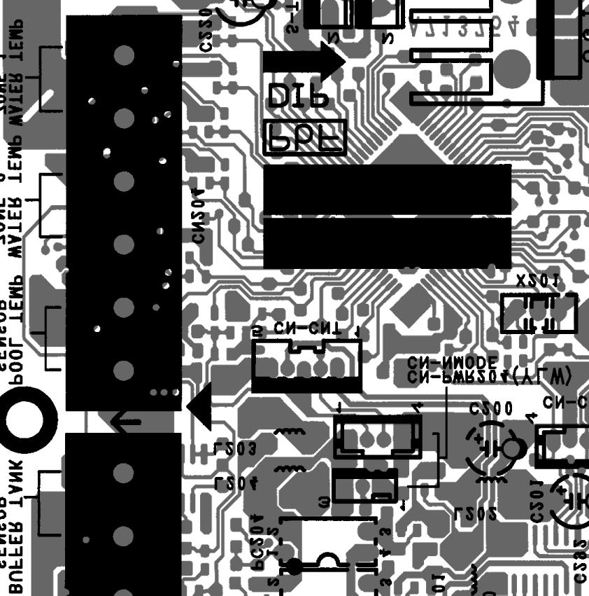
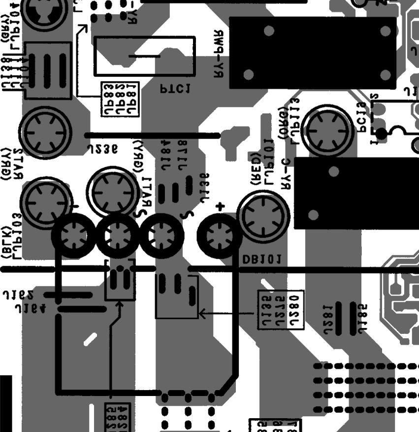
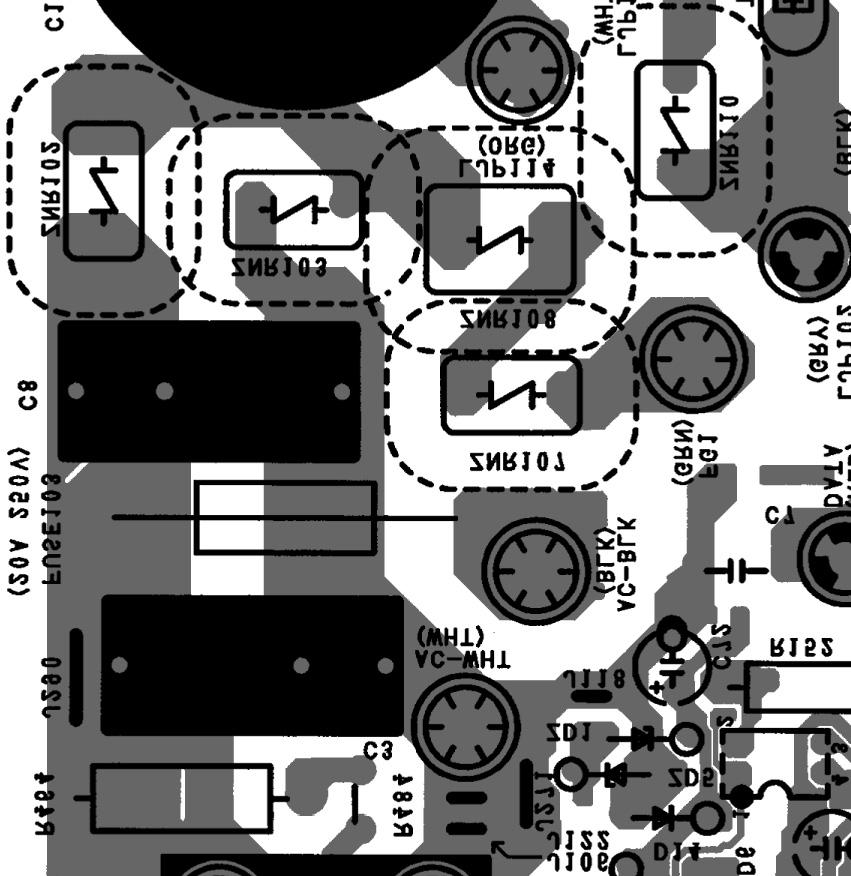
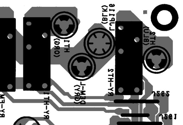
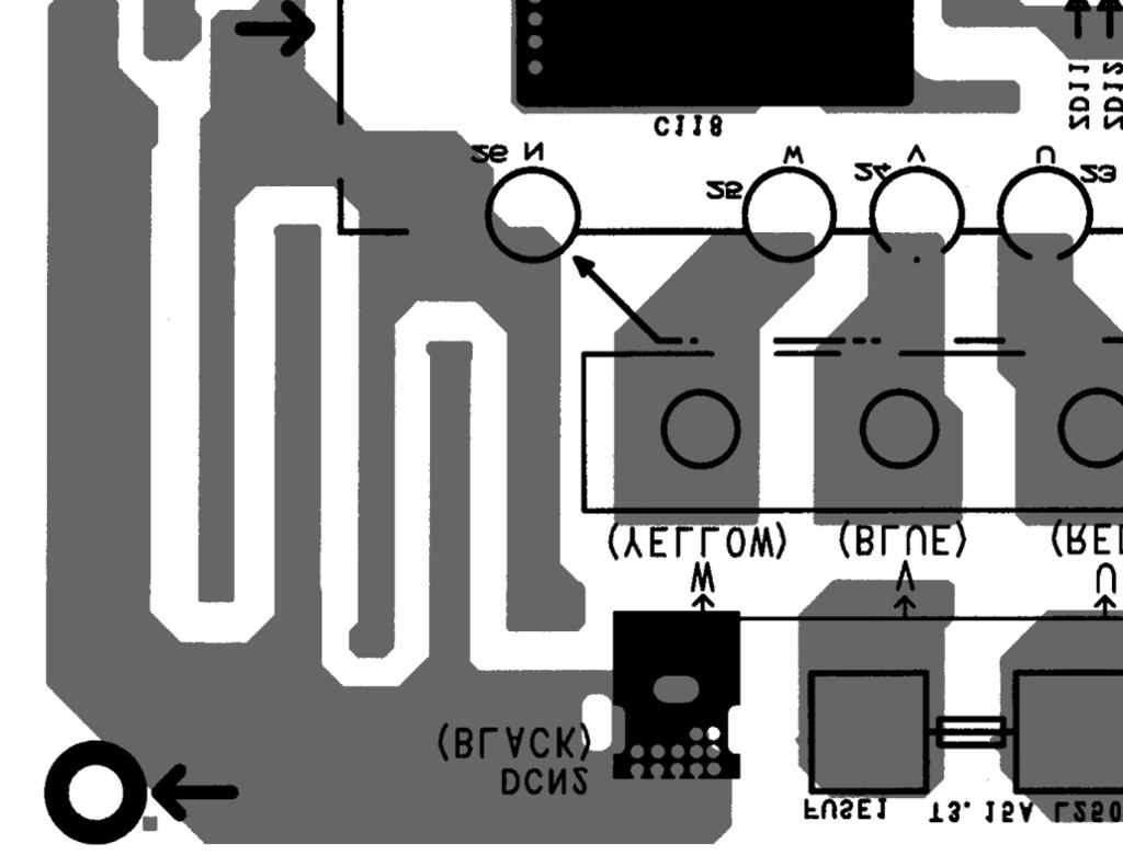
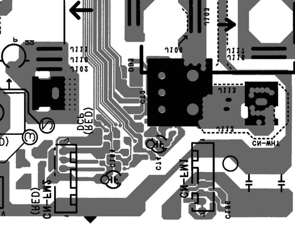
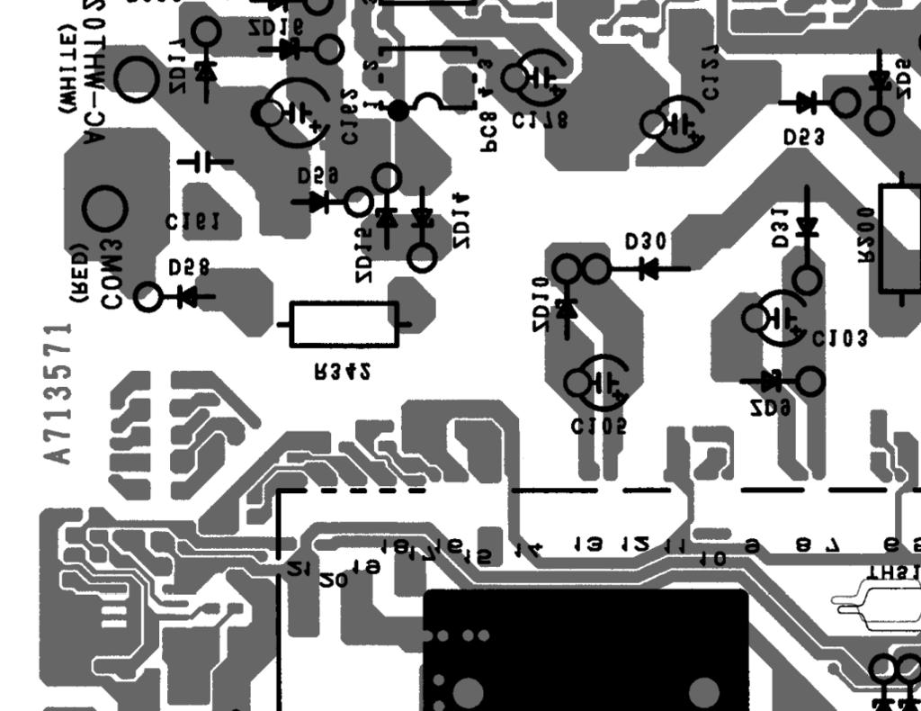
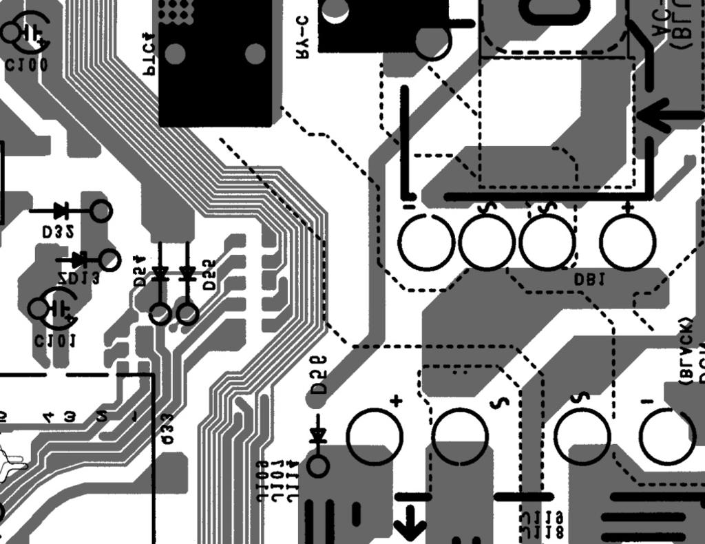
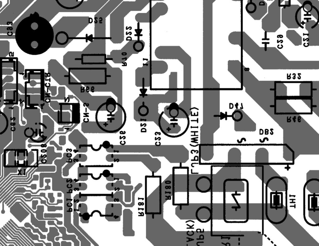
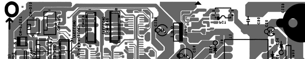
50 10. Printed Circuit Board 10.1 Indoor Unit Main Printed Circuit Board G02 CN-OLP1 G01 CN-PWR2 CN-PWR3 AC1-N DATA AC1-L3 CN-PWR4 CN-FLWSEN CN-TH2 CN-TH1 CN-TH3 CN-CNT CN6 CN3 CN4 CN5 50


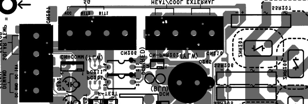

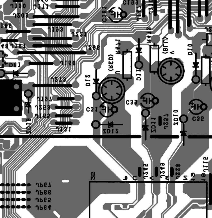
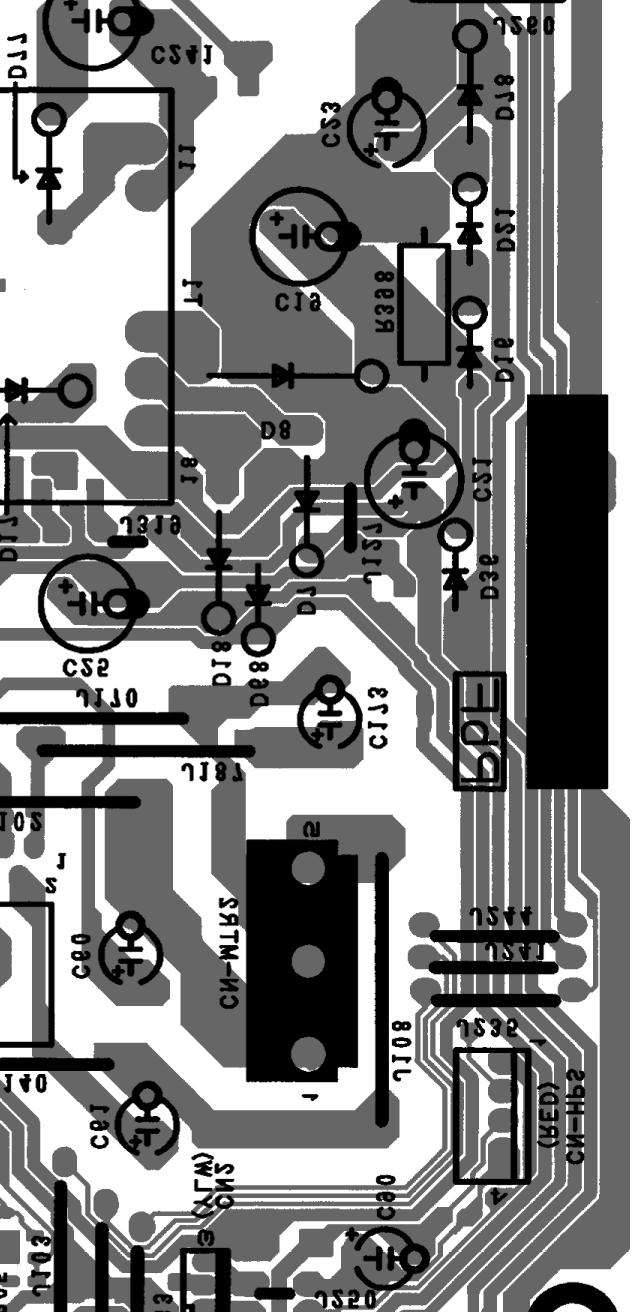
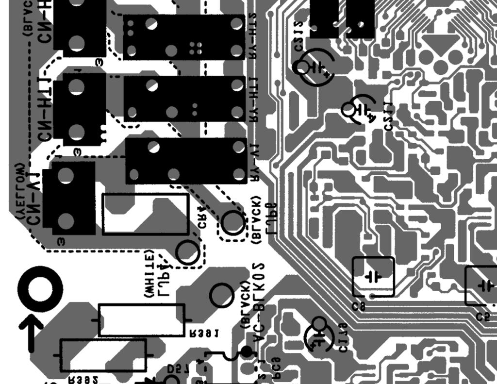
51 Sub Printed Circuit Board (Optional) CN205 CN-PWR204 CN204 CN207 CN-COMM CN-PWR202 CN206 CN210 51


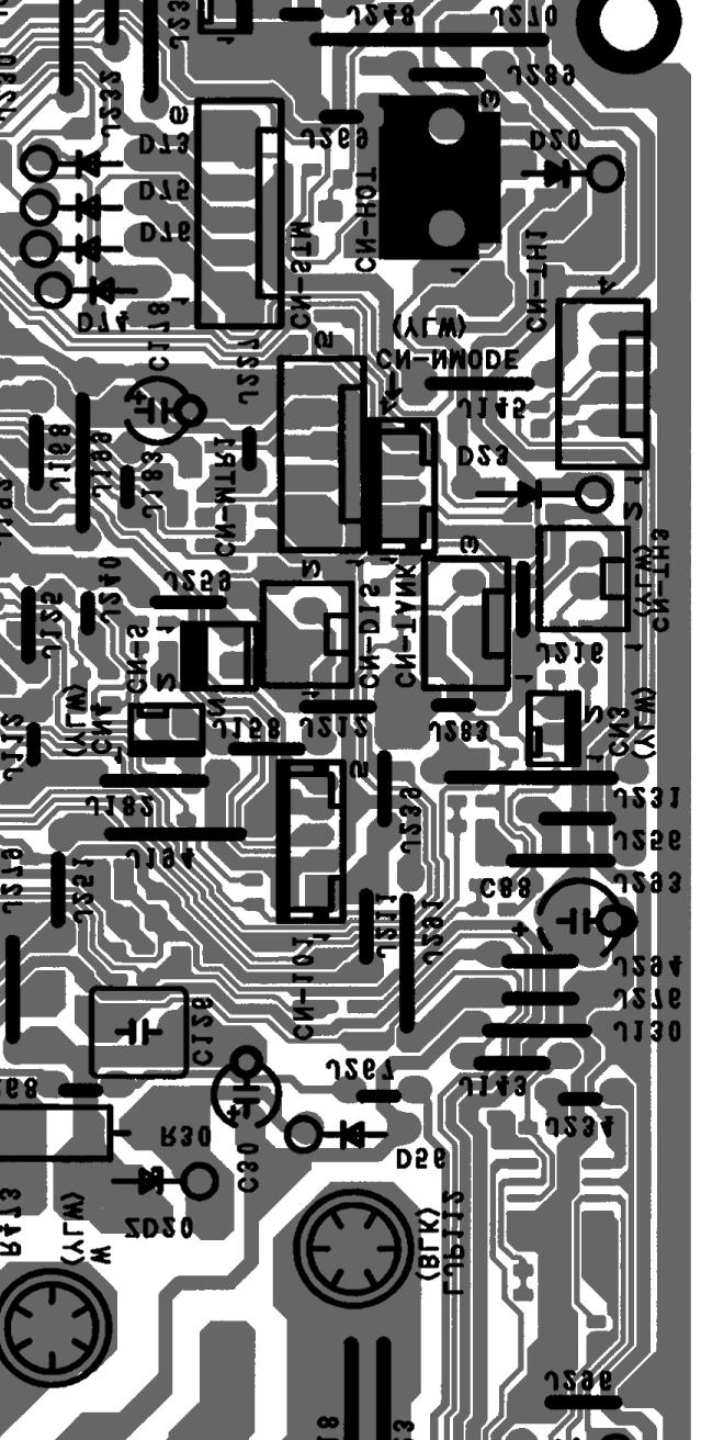


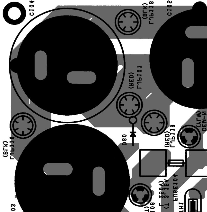
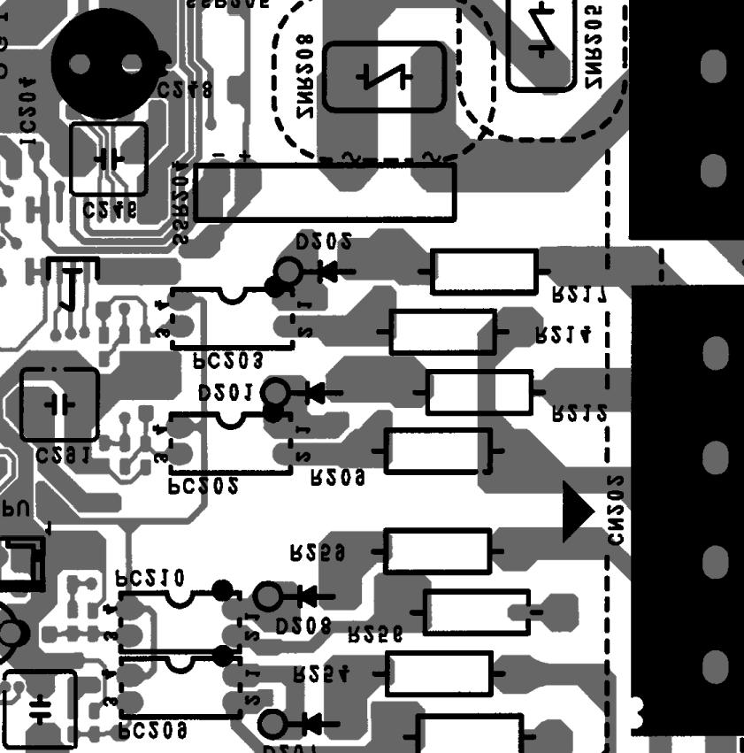
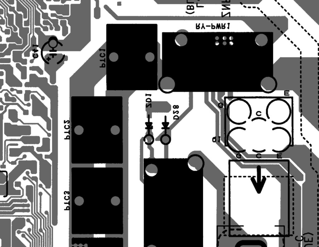
52 10.2 Outdoor Unit Main Printed Circuit Board WH-UD03HE5-1 WH-UD05HE5-1 POWER TRANSISTOR (IPM) CN-TANK CN-DIS CN-TH3 CN-MTR1 CN-TH1 CURRENT TRANSFORMER (CT) CN-STM CN-HOT CN-HPS 52
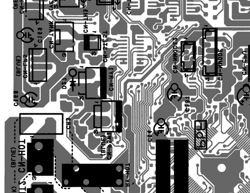
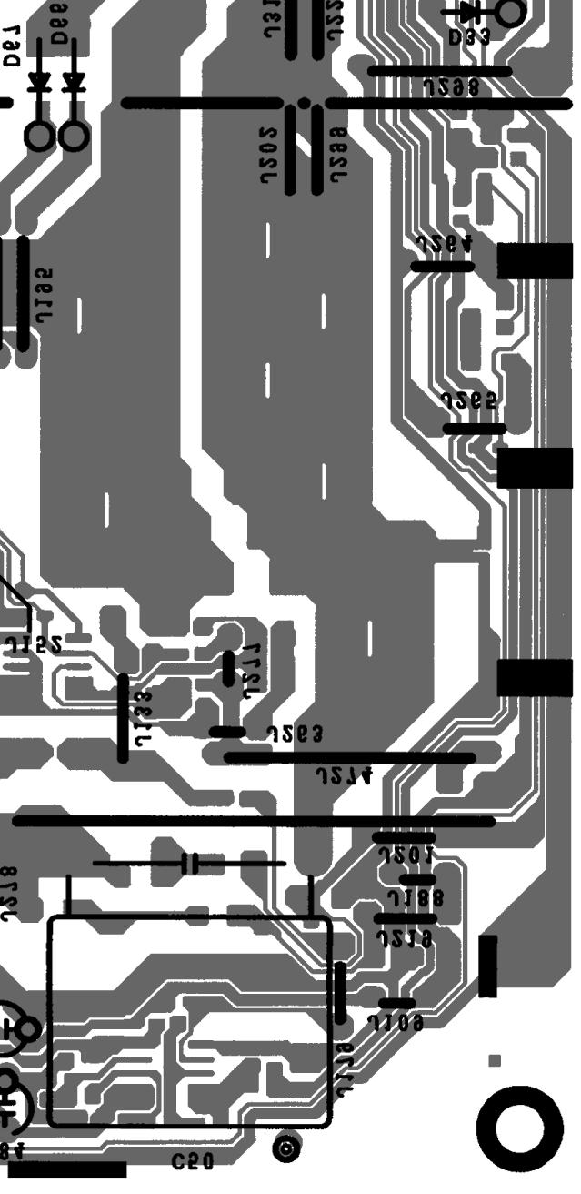
53 WH-UD07HE5-1 WH-UD09HE5-1 CN-FM1 CURRENT TRANSFORMER (CT) POWER TRANSISTOR (IPM) CN-PSW1 CN-TANK CN-HPS CN-TH2 CN-DIS CN-TH1 CN-EV 53

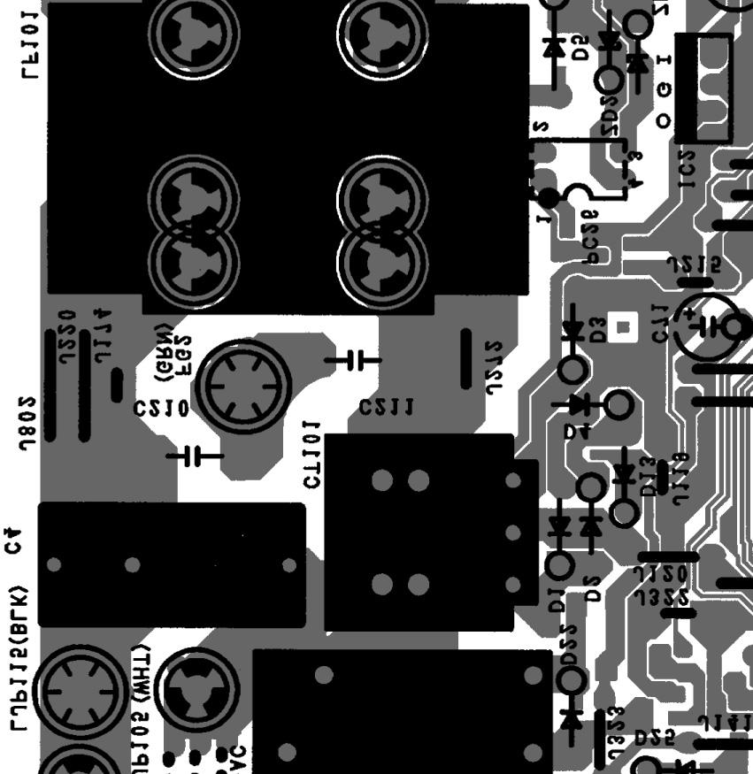
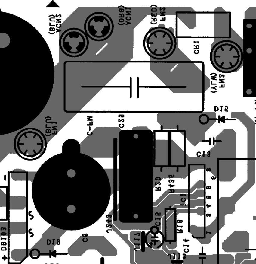
54 ise Filter Printed Circuit Board CN-ACL CN-ACN AC-BLK CN-BLK FG2 CN-WHT FG Capacitor Printed Circuit Board DCP-IN DCN-IN DCN-OUT AC-C 54
55 11. Installation Instruction Field Supply Accessories (Optional). Part Model Specifications Maker i ii 2-way valve kit *Cooling model Room Thermostat Electromotoric Actuator SFA21/18 AC230V Siemens 2-port Valve VVI46/25 Siemens Wired Wireless PAW-A2W-RTWIRED PAW-A2W-RTWIRELESS AC230V - iii Mixing valve AC230V Caleffi iv Pump - Yonos 25/6 AC230V Wilo v Buffer tank sensor - PAW-A2W-TSBU - - vi Outdoor sensor - PAW-A2W-TSOD - - vii Zone water sensor - PAW-A2W-TSHC - - viii Zone room sensor - PAW-A2W-TSRT - - ix Solar sensor - PAW-A2W-TSSO - - It is recommended to purchase the field supply accessories listed in above table Indoor Unit Select the Best Location Install the Tank Unit in indoors with frost free weather proof location only. Must install on a flat horizontal and solid hard surface. There should not be any heat source or steam near the Tank Unit. A place where air circulation in the room is good. A place where drainage can be easily done (e.g. Utility room). A place where Tank Unit s operation noise will not cause discomfort to the user. A place where Tank Unit is far from door way. A place where accessible for maintenance. Ensure to keep minimum distance of spaces as illustrated below from wall, ceiling, or other obstacles. A place where flammable gas leaking might not occur. Secure the Tank Unit to prevent it being knocked over accidentally or during earthquakes Transport and Handling Be careful during transporting the unit so that it is not damaged by impact. Only remove the packaging material once it has reached its desired installation location. It may need three or more people to carry out the installation work. The weight of Tank Unit might cause injury if carried by one person. The Tank Unit can be transported either in vertical or horizontal. o If it transported in horizontal, make sure Front of packaging material (printed with FRONT ) must facing upwards. o If it transported in vertical, use the hand holes on sides, slide and move to the desired location. Fix the Adjustable Feet, if the Tank unit installed on an uneven surface Required space for installation (Unit : mm) Hold Hold arrow section to slide and move Hold Min. 100 Min. 300 Min. 700 Min. 100 Min To Drill a Hole in the Wall and Install a Sleeve of Piping 1 Make a Ø70 mm through hole. 2 Insert the piping sleeve to the hole. 3 Fix the bushing to the sleeve. 4 Cut the sleeve until it extrudes about 15 mm from the wall. CAUTION When the wall is hollow, please be sure to use the sleeve for tube assembly to prevent dangers caused by mice biting the connection cable. 55
56 5 Finish by sealing the sleeve with putty or caulking compound at the final stage Piping Installation Indoor Sleeve for tube assembly ø70 mm through hole Wall Outdoor 15 mm Approx. 5-7 mm Bushing for tube assemblys Putty orcaulking compound Typical Piping Installation Refrigerant Piping Installation This Tank Unit is designed for combination with Panasonic Air-to-Water Heat Pump Outdoor Unit. If Outdoor Unit from other manufacturer are being used in combination with Panasonic Tank Unit, optimum operation and reliability of the system is not guaranteed. Thus warranty cannot be given in such case. 1 Connect Tank Unit to Air-to-Water Heatpump Outdoor Unit with correct piping size. Use Reducing Adapter for Outdoor Unit UD03HE5-1 and UD05HE5-1 Refrigerant Gas piping connection. Model Piping size (Torque) Use Reducing Tank Unit Outdoor Unit Gas Liquid Adapter UD03HE5-1 / UD05HE5-1 ADC0309H3E5 UD07HE5-1 / UD09HE5-1 ø12.7mm (1/2") [55 N m] ø15.88mm (5/8") [65 N m] ø6.35mm (1/4") [18 N m] ø6.35mm (1/4") [18 N m] Fan Coil Unit Spanner Air-to-Water Heatpump Outdoor Unit Radiator / Floor Heater 2-Way Valve Faucet Pressure Relief Valve Drainage Tank Water Discharge Tundish Drain Water Expansion Vessel Check Shut Valve Off Valve Tab / Shower Main Water Supply Pressure Reducing Valve Torque wrench Access to Internal Components WARNING This section is for authorized and licensed electrician/water system installer only. Work behind the front plate secured by screws must only be carried out under supervision of qualified contractor, installation engineer or service person. Hook 2X (screw) CAUTION Open or close the Front Plate carefully. The heavy Bottom Front Plate may injures the fingers. CAUTION Do not overtighten, overtightening may cause gas leakage. 2 Please make flare after inserting flare nut (located at joint portion of tube assembly) onto the copper pipe. (In case of using long piping) 3 Do not use pipe wrench to open refrigerant piping. Flare nut may be broken and cause leakage. Use proper spanner or ring wrench. 4 Connect the piping: o Align the centre of piping and sufficiently tighten the flare nut with fingers. o Further tighten the flare nut with torque wrench in specified torque as stated in the table. Open and Close Top Front Plate 1 Remove the 2 mounting screws of Bottom Front Plate. 2 Slide it upwards to unhook the Bottom Front Plate hook. 3 Reverse above steps 1~2 for close it. 56
57 Cutting and Flaring the Piping 1 Please cut using pipe cutter and then remove the burrs. 2 Remove the burrs by using reamer. If burrs is not removed, gas leakage may be caused. Turn the piping end down to avoid the metal powder entering the pipe. 3 Please make flare after inserting the flare nut onto the copper pipes Pipe Reamer Point down Clamp handle Red arrow mark 1. To cut 2. To remove burrs 3. To flare Improper flaring Inclined Surface Cracked Uneven damaged thickness Water Piping Installation Please engage a licensed water circuit installer to install this water circuit. This water circuit must comply with relevant European and national regulations (including EN61770), and local building regulation codes. Ensure the components installed in the water circuit could withstand water pressure during operation. Do not use worn out tube. Do not apply excessive force to pipes that may damage the pipes. Choose proper sealer which can withstand the pressures and temperatures of the system. Make sure to use two spanners to tighten the connection. Further tighten the nuts with torque wrench in specified torque as stated in the table. Cover the pipe end to prevent dirt and dust when inserting it through a wall. Choose proper sealer which can withstand the pressures and temperatures of the system. If non-brass metallic piping is used for installation, make sure to insulate the pipes to prevent galvanic corrosion. Use correct nut for all Tank Unit tube connections and clean all tubes with tap water before installation. See Tube Position Diagram for detail. Tube Connector Nut Size Torque g & h RP 1¼" N m Bar When properly flared, the internal surface of the flare will evenly shine and be of even thickness. Since the flare part comes into contact with the connections, carefully check the flare finish. i & j RP ¾" 58.8 N m Tank Unit Handle Yoke Core Bar 0 0.5mm Copper pipe CAUTION Do not overtighten, overtightening may cause gas leakage. Make sure to insulate the water circuit pipes to prevent reduction of heating capacity. After installation, check the water leakage condition in connection area during test run. Failure to connect the tube appropriately might cause the Tank Unit malfunction. Protection From Frost: If the Tank Unit is being exposed to frost while power supply failure or pump operating failure, drain the system. When water is idle inside the system, freezing up is very likely to happen which could damage the system. Make sure the power supply is turned off before draining. Heater Assembly may be damaged under dry heating. Corrosion Resistance: Duplex stainless steel is naturally corrosion resistant to mains water supply. specific maintenance is required to maintain this resistance. However, please note that Tank Unit is not guaranteed for use with a private water supply. It is recommended to use a tray (field supply) to collect water from the Tank Unit if water leakage occur. (A) Space Heating/Cooling Pipework Connect Tank Unit Tube Connector g to outlet connector of Zone 1 Panel/Floor heater. Connect Tank Unit Tube Connector h to inlet connector of Panel/Floor heater. Failure to connect the tube appropriately might cause the Tank Unit malfunction. Refer below table for the rated flow rate of each particular Outdoor Unit. Model Rated Flow Rate (l/min) Tank Unit Outdoor Unit Cool Heat ADC0309H3E5 UD03HE UD05HE UD07HE UD09HE (B) Domestic Hot Water Tank Pipework It s strongly recommended to install an expansion vessel (field supply) in the Domestic Hot Water Tank circuit. Refer Typical Piping Installation section to locate the expansion vessel. o Recommended pre-charge pressure of the expansion vessel (field supply) = 0.35MPa (3.5 bars) In high water pressure or water supply is above 500kPa, please install the Pressure Reducing Valve for water supply. If the pressure higher than that, it might damage the Tank Unit. Spanner Torque wrench 57
58 A Pressure Reducing Valve (field supply) with below specification is strongly advised to be installed along the line of the tube connector i of Tank Unit. Refer Typical Piping Installation section to locate both of these valves. Recommended Pressure Reducing Valve specifications: o Set pressure: 0.35 MPa (3.5 bars) Must connect a faucet to Tank Unit Tube Connector i and main water supply, in order to supply water with appropriate temperature for shower or tap usage. Failure to do so might cause scalding. Failure to connect the tube appropriately might causing the Tank Unit malfunction. (C) Pressure Relief Valve Drainage Pipework Connect a drain hose to the Pressure Relief Valve hose outlet h. The hose must be installed in a continuously downward direction and left open to the frost-free atmosphere. If drain hose is long, use a metal support fixture along the way to eliminate the wavy pattern of drain tube. The water may drip from this discharge hose. Therefore must guide the hose without close or block the outlet of the hose. Do not insert this hose into sewage hose or cleaning hose that may generate ammonia gas, sulphuric gas etc. If necessary, use a hose clamp to tighten the hose at drain hose connector to prevent it from leaking. Guide the drain hose to outdoor as illustrated at the right figure. Discharge below fixed grating Fixed grating Trapped gulley Possible wall Illustration of guide drain hose to outdoor (D) Domestic Hot Water Tank Discharge (Drain Tap) and Safety Relief Valve Pipework Safety Relief Valve 0.8MPa (8 bars) incorporated in Domestic Hot Water Tank. Drain Tap and Safety Relief Valve discharge fittings share the same drainage outlet. Use R½" male connector for this drainage outlet connection (Tube connector ). Piping must always be installed in a continuously downward direction. It must not be longer than 2m, with no more than 2 elbows, and must not allow condensation to build up or freezing to occur. The pipe from this drainage outlet fitting must not be shut off. The discharge must be freed. The end of this pipework must be in such a way so that the outlet is visible and cannot cause any damage. Keep away from electrical components. It is recommended to fit a tundish into this pipework. Tundish should be visible and positioned away from frost environment and electrical components. (E) Drain Elbow and Hose Installation Fix the Drain Elbow and Packing to the bottom of Drain Water Hole. Use inner diameter 17 mm drain hose in the market. This hose must to be installed in a continuously downward direction and in a frost-free environment. Improper drain piping may cause water leakage hence damage the furnitures. Guides this hose outlet to outdoor only. Do not insert this hose into sewage or drain pipe that may generate ammonia gas, sulphuric gas, etc. If necessary, use hose clamp to further tighten the hose at drain hose connector to prevent leakage. Water will drip from this hose, therefore the outlet of this hose must be installed in an area where the outlet cannot become blocked. Packing 4 Drain Elbow Air-Tightness Test on the Refrigerating System Before system charged with refrigerant and before the refrigerating system in put into operation, below site test procedure and acceptance criteria shall be verified by the certified technicians, and/or the installer:- Step 1: Pressure test for refrigerant leak detection: 1) Steps for pressure test, in accordance to ISO ) Evacuate the system from refrigerant before the leak test, attach the gauge manifold set correctly and tightly. Charging hose of Low side connect to Gas side. (Charging hose of High side connect to Liquid side if applicable.) 3) Adjust the knob on the service valves, and regulator on the gauge set, so that test gas can be inserted through the centre manifold of the gauge set. 4) Insert Nitrogen gas into the system through the centre manifold and wait until the pressure within the system to reach about 1MPa (10 BarG) wait for a few hours and monitor the pressure reading on the gauges. 58
59 5) Please note that the system s pressure may rise slightly if the test is carried out on mid day, due to temperature rise. The inverse may happen when there is temperature drop at night. However, this variation will be minimal. 6) Waiting time depends on the size of the system. Larger systems may require 12 hours of waiting time. Leak detection within smaller system can be achieved in 4 hours. 7) Check if there is a constant pressure drop. Move to next step Step 2: Refrigerant leak detection... if there is any pressure drop. Otherwise, release the Nitrogen gas and, move to Step 3: Vacuum test. 8) Next, insert a small amount of same refrigerant into the system through the centre hose, until the pressure reaches about 1MPa (10 BarG). Step 3: Vacuum test: 1) Perform Vacuum test to check leak / moisture if present. 2) Refer to section EVACUATION OF THE EQUIPMENT to vacuum gas out of the air conditioning system. 3) Wait for a few hours, depending on the size of the refrigerating system and monitor the pressure rise. If the pressure rises until 1 bar absolute, then there is leak. If the pressure rises, but it is lower than 1 bar absolute, then moisture is present. Next, remove the moisture, or repair, and redo the refrigerant leak testing, starting from Step 1: Pressure test. (Low/Gas) pressure gauge 7 (High/Liquid) pressure gauge (Low/Gas) pressure gauge (High/Liquid) pressure gauge Handle 2 N 2 R-### 2 An example illustrations of setup for refrigerant leak detection. Vacuum pump 2 An example illustrations of setup for refrigerant leak detection. Step 2: Refrigerant leak detection through Electronic halogen leak detector and/or ultrasonic leak detector: 1) Use any one of below detector to check leaking. i) Electronic halogen leak detector. i-a) Switch on the unit. i-b) Cover the test area from direct draft. i-c) Pass the detection probe near test area and wait for audible and visible signals. ii) Ultrasonic Leak Detector ii-a) Make sure the area is quiet. ii-b) Switch on the ultrasonic leak detector. ii-c) Move the probe along your air conditioning system to test for leaks, and mark for repair. 2) Any leak detected at this level shall be repaired and retested, starting from Step 1: Pressure test. NOTE: - Always recover the refrigerant and Nitrogen gas into recovery cylinder after completion of a test. - You must use the detection equipment with Detectable Leak Rate of 10-6 Pa.m 3 /s or better. - Do not use refrigerant as test medium for system with total refrigerant charge more than 5kg. - Test shall be performed with dry Nitrogen or another non-flammable, non-reactive, dried gas. Oxygen, air or mixtures containing them shall not be used. 59
60 Connect the Cable to Tank Unit WARNING This section is for authorized and licensed electrician only. Work behind the Control Board Cover secured by screws must only be carried out under supervision of qualified contractor, installation engineer or service person Fixing of Power Supply Cable and Connecting Cable 1 Connecting cable between Tank Unit and Outdoor Unit shall be approved polychloroprene sheathed flexible cord, type designation IEC 57 or heavier cord. See below table for cable size requirement. Tank Unit ADC0309H3E5 Model Outdoor Unit Connecting Cable Size UD03HE5-1 / UD05HE5-1 4 x 1.5 mm 2 UD07HE5-1 / UD09HE5-1 4 x 2.5 mm 2 o Ensure the colour of wires of Outdoor Unit and the terminal no. are the same to the Tank Unit respectively. o Earth wire shall be longer than the other wires as shown in the figure for the electrical safety in case of the slipping out of the cord from the Holder (Clamper). 2 An isolating device must be connected to the power supply cable. o Isolating device (disconnecting means) should have minimum 3.0 mm contact gap. o Connect the approved polychloroprene sheathed power supply 1 cord and power supply 2 cord and type designation IEC 57 or heavier cord to the terminal board, and to the other end of the cord to isolating device (Disconnecting means). See below table for cable size requirement. Tank Unit ADC0309H3E5 Model Outdoor Unit UD03HE5-1 / UD05HE5-1 UD07HE5-1 / UD09HE5-1 Power Supply Cord Cable Size Isolating Devices Recommended RCD 1 3 x 1.5 mm 2 15/16A 30mA, 2P, type A 2 3 x 1.5 mm 2 15/16A 30mA, 2P, type AC 1 3 x 2.5 mm 2 25A 30mA, 2P, type A 2 3 x 1.5 mm 2 15/16A 30mA, 2P, type AC 3 To avoid the cable and cord being damaged by sharp edges, the cable and cord must be passed through a bushing (located at the bottom of Control Board) before terminal board. The bushing must be used and must not be removed. Terminals on the Outdoor Unit Colour of wires (Connecting cables) RCCB/ELCB Terminal Board Terminals on the Tank unit L N L1 N *1 *1 (Power Supply Cord) Holder (Clamper) Tank Unit/ Terminals on the isolating L N L1 N1 Outdoor Unit devices from power supply Bushing connection (Disconnecting means) Power Supply 1 Power Supply 2 Connecting Cable Power Supply Cable Terminal screw Tightening torque cn cm {kgf cm} M4 157~196 {16~20} M5 196~245 {20~25) *1 - Earth wire must be longer than other cables for safety reasons 60
61 Wire Stripping and Connecting Requirement 10 ± 1mm Wire stripping loose strand when insert Indoor/outdoor connecting terminal board 5mm or more (gap between wires) Conductor fully insert ACCEPT Conductor over insert PROHIBITED Conductor not fully insert PROHIBITED Connecting Requirement For Tank Unit with UD03HE5-1/UD05HE5-1 The equipment s Power Supply 1 complies with IEC/EN The equipment s Power Supply 1 complies with IEC/EN and can be connected to current supply network. The equipment s Power Supply 2 complies with IEC/EN The equipment s Power Supply 2 complies with IEC/EN and shall be connected to suitable supply network, with the following maximum permissible system impedance Z max = ohm (Ω) at the interface. Please liaise with supply authority to ensure that the Power Supply 2 is connected only to a supply of that impedance or less. For Tank Unit with UD07HE5-1/UD09HE5-1 This equipment s Power Supply 1 complies with IEC provided that the short circuit power S sc is greater than or equal to kW at the interface point between the user s supply and the public system. It is the responsibility of the installer or user of the equipment to ensure, by consultation with the distribution network operator if necessary, that the equipment is connected only to a supply with a short circuit power S sc greater than or equal to kW. The equipment s Power Supply 1 complies with IEC/EN and shall be connected to a suitable supply network, having services current capacity 100A per phase. Please liaise with supply authority that the service current capacity at the interface point is sufficient for the installation of the equipment. The equipment s Power Supply 2 complies with IEC/EN The equipment s Power Supply 2 complies with IEC/EN and shall be connected to suitable supply network, with the following maximum permissible system impedance Z max = ohm (Ω) at the interface. Please liaise with supply authority to ensure that the Power Supply 2 is connected only to a supply of that impedance or less Charging and Discharging the Water Make sure all the piping installations are properly done before carry out below steps Charge the Water For Domestic Hot Water Tank 1 Set the Domestic Hot Water Tank Discharge (Drain Tap) to CLOSE. CLOSE OPEN Domestic Hot Water Tank Discharge (Drain Tap) g 2 Set all Tap / Shower OPEN. 3 Start filling water to the Domestic Hot Water Tank via Tube Connector i. After 20~40min, water should flow out from Tap / Shower. Else, please contact your local authorized dealer. 4 Check and make sure no water leaking at the tube connecting points. 5 Set the Domestic Hot Water Tank Discharge (Drain Tap) to OPEN for 10 seconds to release air from this pipeline. Then set it CLOSE. 6 Turn the Safety Relief Valve knob counterclockwise slightly and hold for 10 seconds to release air from this pipeline. Then recover the knob to original position. 7 Ensure Step 5 & 6 is carried out each time after charging water to Domestic Hot Water Tank. 8 To prevent back pressure from happening to the Safety Relief Valve, do turn the Safety Relief Valve knob counterclockwise. For Space Heating / Cooling 1 Turn the plug on the Air Purge Valve outlet anticlockwise by one complete turn from fully closed position. Air purge valve a Plug (turn anticlockwise by one complete turn) 61
62 2 Set the Pressure Relief Valve level DOWN. 3 Start filling water (with pressure more than 0.1 MPa (1 bar)) to the Space Heating / Cooling circuit via Tube Connector g. Stop filling water if the free water flow through Pressure Relief Valve Drainage. 4 Turn ON the Tank Unit and make sure Water Pump and Water Pump are running. 5 Check and make sure no water leaking at the tube connecting points Discharge the Water For Domestic Hot Water Tank 1 Turn OFF power supply. 2 Set the Domestic Hot Water Tank Discharge (Drain Tap) to OPEN. 3 Open Tap / Shower to allow air inlet. 4 Turn the Safety Relief Valve knob counterclockwise slightly and hold it until all air is released from this pipeline. Then recover the knob to original position after ensured the pipeline is emptied. 5 After discharge, set Domestic Hot Water Tank Discharge (Drain Tap) to CLOSE Reconfirmation WARNING Be sure to switch off all power supply before performing each of the below checkings Check Water Pressure *(0.1 MPa = 1 bar) Water pressure should not lower than 0.05 MPa (with inspects the Water Pressure Gauge). If necessary add water into Tank Unit (via Tube Connector g) Lever Turn up Pressure relief valve b Pressure relief valve b Check Pressure Relief Valve Check for correct operation of Pressure Relief Valve by turning on the lever to become horizontal. If you do not hear a clacking sound (due to water drainage), contact your local authorized dealer. Push down the lever after finish checking. In case the water keep on draining out from the Tank Unit, switch off the system, and then contact your local authorized dealer Expansion Vessel Pre Pressure Checking For Space Heating / Cooling Expansion Vessel with 10 L air capacity and initial pressure of 1 bar is installed in this Tank Unit. Total amount of water in system should be below 200 L. (Inner volume of Tank Unit s piping is about 5 L) If total amount of water is over 200 L, please add another expansion vessel. (field supply) Please keep the installation height difference of system water circuit within 10 m Check RCCB/ELCB Ensure the RCCB/ELCB set to ON condition before check RCCB/ELCB. Turn on the power supply to the Tank Unit. This testing could only be done when power is supplied to the Tank Unit. WARNING Be careful not to touch parts other than RCCB/ELCB test button when the power is supplied to Tank Unit. Else, electrical shock may happen. Push the TEST button on the RCCB/ELCB. The lever would turn down and indicate 0, if it functions normal. Contact authorized dealer if the RCCB/ELCB malfunction. Turn off the power supply to the Tank Unit. If RCCB/ELCB functions normal, set the lever to ON again after testing finish Installation of Remote Controller as Room Thermostat Remote Controller mounted to the Tank Unit can be moved to the room and serve as Room Thermostat Installation Location Install at the height of 1 to 1.5 m from the floor (Location where average room temperature can be detected). Install vertically against the wall. Avoid the following locations for installation. 1 By the window, etc. exposed to direct sunlight or direct air. 2 In the shadow or backside of objects deviated from the room airflow. 3 Location where condensation occurs (The Remote Controller is not moisture proof or drip proof.) 4 Location near heat source. 5 Uneven surface. Keep distance of 1 m or more from the TV, radio and PC. (Cause of fuzzy image or noise) 62
63 Remote Controller Wiring Remote Controller cable shall be (2 x min 0.3 mm 2 ), of double insulation PVC-sheathed or rubber sheathed cable. Total cable length shall be 50 m or less. Be careful not to connect cables to other terminals of Tank Unit (e.g. power source wiring terminal). Malfunction may occur. Do not bundle together with the power source wiring or store in the same metal tube. Operation error may occur Tank Unit Remote Controller wiring (field supply) polarity Terminal for Remote Controller wiring Remote Controller Remove The Remote Controller From Tank Unit Remove the top case from the bottom case Mounting The Remote Controller For exposed type Preparation: Make 2 holes for screws using a driver. Mount the top case. Align the claws of the top case and then align the claws of the bottom case. Cut here with a nipper and remove the burr withafile. Claw (2 places) UP Hole for screw Screw (field supply) Connect the remote control wiring Arrange the wires along the groove of the case. Mount the bottom case to the wall. Claw (2 places) Pass through the hole Wall to which the remote controller is fixed Clamper (field supply) Insert the driver and slightly turn. Bottom case (Back side) Top case (Back side) Remote controller terminal board Remove the coating. Approx. 6 mm Remove the sheath. Approx. 180 mm. Make sure the wiring connection is in the correct direction. Bottom case Flat-blade screwdriver For embedded type Preparation: Make 2 holes for screws using a driver. Remove the wiring between Remote controller and Tank Unit terminal. Mount the top case. Align the claws of the top case and then align the claws of the bottom case. Mount the bottom case to the wall. Pass the wire through the hole in the centre of the bottom case. Avoid the wire being caught. UP Claw (2 places) Claw (2 places) Hole for screw Screw (field supply) Claw (2 places) Disconnect the Remote controller wiring Connect the remote control wiring Bottom case (Back side) Top case (Back side) Remote controller terminal board Remove the coating. Approx. 6 mm Make sure the wiring connection is in the correct direction. 63
64 Replace The Remote Controller Cover Replace the existing Remote controller cover with Remote controller cover to close the hole left after remove the Remote controller. 1 Release the Remote controller cover s hooks from behind the Front Plate. Front Plate Existing Remote controller cover 2 Press from front to fix the Remote controller cover on the front plate. Front Plate Hook (6 places) For normal operation, Water Pressure Gauge reading should be in between 0.05 MPa and 0.3 MPa. If necessary, adjust the Water Pump SPEED accordingly to obtain normal water pressure operating range. If adjust Water Pump SPEED cannot solve the problem, contact your local authorized dealer. After test run, please clean the Water Filter Set. Reinstall it after finish cleaning Check Water Flow of Water Circuit Confirm the maximum water flow during main pump operation not less than 15 l/min. *Water flow can be check through service setup (Pump Max Speed) [Heating operation at low water temperature with lower water flow may trigger H75 during defrost process.] Reset Overload Protector Overload Protector a serves the safety purpose to prevent the water over heating. When the Overload Protector a trip at high water temperature, take below steps to reset it. Take out the cover. Use a test pen to push the centre button gently in order to reset the Overload Protector. Fix the cover to the original fixing condition. Remote controller cover Hook (6 places) Use test pen to push this button for reset Overload protector Test Run Before test run, make sure below items have been checked:- o Pipework are properly done. o Electric cable connecting work are properly done. o Tank Unit is filled up with water and trapped air is released. o Please turn on the power supply after filling the tank until full. o In order to check whether the tank is full, switch heater once for about 10 min. Switch ON the power supply of the Tank Unit. Set the Tank Unit RCCB /ELCB to ON condition. Then, please refer to the Operation Instruction for operation of Remote Controller Maintenance In order to ensure safety and optimal performance of the Tank Unit, seasonal inspections on the Tank Unit, functional check of RCCB/ELCB, field wiring and piping have to be carried out at regular intervals. This maintenance should be carried out by authorized dealer. Contact dealer for scheduled inspection Maintenance for Water Filter Set Turn OFF power supply. Set the two valves for the Water Filter Set to CLOSE. Take off the clip, then gently pull out the mesh. Beware of small amount water drain out from it. Clean the mesh with warm water to remove all the stain. Use soft brush if necessary. Reinstall the mesh to the Water Filter Set and set back the clip on it. Set the two valves for the Water Filter Set to OPEN. Turn ON power supply. 64
65 Maintenance for Safety Relief Valve It is strongly recommended to operate the valve by turn the knob counter clockwise to ensure free water flow through discharge pipe at regular intervals to ensure it is not blocked and to remove lime deposit Proper Pump Down Procedure WARNING Strictly follow the steps below for proper pump down procedure. Explosion may occur if the steps are not followed as per sequence. 1. When the Tank Unit is not in operation (standby), press the SERVICE switch on the Remote Controller to enter SERVICE mode. Operate the system in Sr : 01 mode for pump down operation. 2. After 10~15 minutes, (after 1 or 2 minutes in case very low ambient temperatures (< 10 C)), fully close 2 way valve on Outdoor Unit. 3. After 3 minutes, fully close 3 way valve on Outdoor Unit. 4. Press the OFF/ON switch on the Remote Controller to stop pump down operation. 5. Remove the refrigerant piping. 65
66 11.2 Outdoor Unit Attached accessories. Accessories part Qty.. Accessories part Qty. Drain elbow Banding strap 1 2 Rubber cap 1 3 7or8 (Depend on Model) 4 (For UD07*E5* and UD09*E5* only) Protective bushing (For UD07*E5* and UD09*E5* only) 3 2 Optional Accessory. Accessories part Qty. Base Pan Heater CZ-NE2P (For UD03*E5* and UD05*E5* only) 5 CZ-NE3P (For UD07*E5* and UD09*E5* only) 1 It is strongly recommended to install a Base Pan Heater (optional) if the outdoor unit is install in cold climate area. Refer the Base Pan Heater (optional) installation instruction for details of installation. Applicable Piping Kit (For UD07*E5* and UD09*E5* only) CZ-52F5,7,10BP Select the Best Location If an awning is built over the unit to prevent direct sunlight or rain, be careful that heat radiation from the condenser is not obstructed. Avoid installations in areas where the ambient temperature may drop below -20 C. Keep the spaces indicated by arrows from wall, ceiling, fence or other obstacles. Do not place any obstacles which may cause a short circuit of the discharged air. If outdoor unit installed near sea, region with high content of sulphur or oily location (e.g. machinery oil, etc), it lifespan maybe shorten. When installing the product in a place where it will be affected by typhoon or strong wind such as wind blowing between buildings, including the rooftop of a building and a place where there is no building in surroundings, fix the product with an overturn prevention wire, etc. (Overturn prevention fitting model number: K-KYZP15C) (For UD07*E5* and UD09*E5* only) If piping length is over 10 m, additional refrigerant should be added as shown in the table. Model UD03*E5* and UD05*E5* UD07*E5* and UD09*E5* Gas Piping size Liquid Rated Length (m) Max. Elevation (m) Min. Piping Length (m) Max. Piping Length (m) Additional Refrigerant (g/m) ø12.7mm (1/2") ø6.35mm (1/4") ø15.88mm (5/8") ø6.35mm (1/4") Example: For UD03*E5* If piping length is 15m, the quantity of additional refrigerant should be 100g. [(15-10)m x 20 g/m = 100g] Install the Outdoor Unit Installation Diagram It is advisable to avoid more than 2 blockage directions. For better ventilation & multiple-outdoor installation, please consult authorized dealer/specialist. This illustration is for explanation purposes only. 100mm or more 1000mm or more 100mm or more 300mm or more Vinyl tape (Wide) Saddle Indoor unit/outdoor unit connecting cable (4-CORE WIRE/1.5 mm 2 ) Type designation IEC 57 or heavier cable ø6.35mm (1/4") Liquid refrigerant piping ø12.7mm (1/2") Gas refrigerant piping 100mm or more 1000mm or more 100mm or more 300mm or more [ Vinyl tape (Wide) Saddle Indoor unit/outdoor unit connecting cable (4-CORE WIRE/ 2.5 mm 2 ) Type designation IEC 57 or heavier cable ø6.35mm (1/4") Liquid refrigerant piping ø15.88mm (5/8") Gas refrigerant piping Check that the cables do not touch the compressor, etc. ] For UD03*E5* and UD05*E5* For UD07*E5* and UD09*E5* 66
67 E F A (Anchor pitch) B C D (Anchor pitch) Model A B C D E F UD03*E5* and UD05*E5* UD07*E5* and UD09*E5* (Unit : mm) After selecting the best location, start installation according to Installation Diagram. 1 Fix the unit on concrete or rigid frame firmly and horizontally by bolt nut (ø10 mm). 2 When installing at roof, please consider strong wind and earthquake. Please fasten the installation stand firmly with bolt or nails Disposal of Outdoor Unit Drain Water When a Drain elbow is used, please ensure to follow below: o the unit should be placed on a stand which is taller than 50 mm. o cover the ø20mm holes with Rubber cap (refer to illustration below). o use a tray (field supply) when necessary to dispose the outdoor unit drain water. If the unit is used in an area where temperature falls below 0 C for 2 or 3 consecutive days, it is recommended not to use the Drain elbow and Rubber cap, for the drain water freezes and the fan will not rotate. Drain elbow 1 Drain elbow 1 Rubber cap 2 x7 UD03*E5* and UD05*E5* Rubber cap 2 x8 UD07*E5* and UD09*E5* Connecting the Piping Connecting the Piping to Outdoor Unit Decide piping length and then cut by using pipe cutter. Remove burrs from cut edge. Make flare after inserting the flare nut (locate at valve) onto the copper pipe. Align center of piping to valves and then tighten with torque wrench to the specified torque as stated in the table. Spanner or Wrench Torque wrench Model UD03*E5* and UD05*E5* UD07*E5* and UD09*E5* Piping size (Torque) Gas Liquid ø12.7mm (1/2") ø6.35mm (1/4") [55 N m] [18 N m] ø15.88mm (5/8") ø6.35mm (1/4") [65 N m] [18 N m] Close the tube joining area with putty heat insulator (local supply) without any gap as shown in right figure. (To prevent insects or small animal entering.) (For UD07*E5* and UD09*E5* only) Be sure to use two spanners to tighten. (If the nuts are overtightened, it may cause the flares to break or leak.) Putty or Heat insulator (local supply) Cutting and Flaring the Piping 1 Please cut using pipe cutter and then remove the burrs. 2 Remove the burrs by using reamer. If burrs is not removed, gas leakage may be caused. Turn the piping end down to avoid the metal powder entering the pipe. 3 Please make flare after inserting the flare nut onto the copper pipes. Pipe Handle Reamer Bar Bar Yoke Core Point Clamp down handle Red arrow mark 1. To cut 2. To remove burrs 3. To flare 0 0.5mm Copper pipe Improper flaring Inclined Surface Cracked Uneven damaged thickness When properly flared, the internal surface of the flare will evenly shine and be of even thickness. Since the flare part comes into contact with the connections, carefully check the flare finish. 67
68 Evacuation of the Equipment WHEN INSTALLING AN AIR-TO-WATER HEAT PUMP, BE SURE TO EVACUATE THE AIR INSIDE THE UNIT AND PIPES in the following procedure. Indoor unit Liquid side Two-way valve Outdoor unit Close Gas side Vacuum pump adaptor Three-way valve Close Vacuum pump CLOSE OPEN 1 Connect a charging hose with a push pin to the Low side of a charging set and the service port of the 3-way valve. o Be sure to connect the end of the charging hose with the push pin to the service port. 2 Connect the center hose of the charging set to a vacuum pump with check valve, or vacuum pump and vacuum pump adaptor. 3 Turn on the power switch of the vacuum pump and make sure that the needle in the gauge moves from 0 cmhg (0 MPa) to 76 cmhg ( 0.1 MPa). Then evacuate the air approximately ten minutes. 4 Close the Low side valve of the charging set and turn off the vacuum pump. Make sure that the needle in the gauge does not move after approximately five minutes. te : BE SURE TO FOLLOW THIS PROCEDURE IN ORDER TO AVOID REFRIGERANT GAS LEAKAGE. 5 Disconnect the charging hose from the vacuum pump and from the service port of the 3-way valve. 6 Tighten the service port caps of the 3-way valve at a torque of 18 N m with a torque wrench. 7 Remove the valve caps of both of the 2-way valve and 3-way valve. Position both of the valves to OPEN using a hexagonal wrench (4 mm). 8 Mount valve caps onto the 2-way valve and the 3-way valve. o Be sure to check for gas leakage. CAUTION If gauge needle does not move from 0 cmhg (0 MPa) to 76 cmhg ( 0.1 MPa), in step 3 above take the following measure: 1. If the leak stops when the piping connections are tightened further, continue working from step If the leak does not stop when the connections are retightened, repair location of leak. 3. Do not release refrigerant during piping work for installation and reinstallation. Take care of the liquid refrigerant, it may cause frostbite Connect the Cable to the Outdoor Unit (FOR DETAIL REFER TO WIRING DIAGRAM AT UNIT) 1 Remove the control board cover from the unit by loosening the screw. 2 Connecting cable between indoor unit and outdoor unit shall be approved polychloroprene sheathed flexible cable (see below table), type designation IEC 57 or heavier cable. Models Flexible cable specification UD03*E5* and UD05*E5* 4 x (1.5 mm 2 ) UD07*E5* and UD09*E5* 4 x (2.5 mm 2 ) Terminals on the indoor unit Colour of wires Terminals on the outdoor unit Terminal Board Earth Wire must be longer than others cables for safety reason. Holder (Clamper) WARNING 3 Secure the cable onto the control board with the holder (clamper). 4 Attach the control board cover back to the original position with screw. This equipment must be properly earthed. 68
69 Wire Stripping and Connecting Requirement 10 ± 1 mm Wire stripping Indoor/outdoor connecting terminal board Conductor fully insert Conductor over insert Conductor not fully insert loose strand when insert 5mmormore (gap between wires) ACCEPT PROHIBITED PROHIBITED (For UD07*E5* and UD09*E5* only) Select required direction and apply protective bushing provided in accessories to protect cables from sharp edges. Once all wiring work has been completed, tie the cable and cord together with the binding strap so that they do not touch other parts such as the compressor and bare copper pipes. Outdoor Unit Terminal Board Cord clamp Protective bushing 4 Selection of direction Banding strap 3 Connecting cable (refer below diagram for its guiding) Apply cut DETAIL OF CONNECTING CABLE GUIDING Pipe Insulation 1 Please carry out insulation at pipe connection portion as mentioned in Indoor/Outdoor Unit Installation Diagram. Please wrap the insulated piping end to prevent water from going inside the piping. 2 If drain hose or connecting piping is in the room (where dew may form), please increase the insulation by using POLY-E FOAM with thickness 6 mm or above. 69
70 11.3 Appendix Variation of system This section introduces variation of various systems using Air-To-Water Heatpump and actual setting method Introduce application related to temperature setting Temperature setting variation for heating 1. Remote Controller Outdoor Indoor Setting of remote controller Installer setting System setup Optional PCB connectivity - Zone & Sensor: Water temperature Floor heating Connect floor heating or radiator directly to the Tank Unit. Remote controller is installed on Tank Unit. This is the basic form of the most simple system. 2. Room Thermostat Indoor Tank Unit receive Room Thermo signal (ON/OFF) from Remote controller to control HP and circulation pump. There is a build-in thermistor in the remote controller. Setting of remote controller Outdoor Floor heating Installer setting System setup Optional PCB connectivity - Zone & Sensor: Room thermostat Internal Connect floor heating or radiator directly to the Tank Unit. Remove remote controller from Tank Unit and install it in the room where floor heating is installed. This is an application that uses remote controller as Room Thermostat. 3. External Room Thermostat Outdoor Indoor Room Thermostat (Field supply) Setting of remote controller Installer setting System setup Optional PCB connectivity - Floor heating Zone & Sensor: Room thermostat (External) Connect floor heating or radiator directly to Tank Unit. Remote controller is installed on Tank Unit. Install separate external Room Thermostat (field supply) in the room where floor heating is installed. This is an application that uses external Room Thermostat. 70
71 4. Room Thermistor Indoor Tank Unit compare between room temperature and setting temperature on the Remote controller to control HP and circulation pump. Outdoor Max: 30m Thermistor Floor heating Setting of remote controller Installer setting System setup Optional PCB connectivity - Zone & Sensor: Room thermistor Connect floor heating or radiator directly to Tank Unit. Remote controller is installed on Tank Unit. Install separate external room thermistor (specified by Panasonic) in the room where floor heating is installed. This is an application that uses external room thermistor. There are 2 kinds of circulation water temperature setting method. Direct: set direct circulation water temperature (fixed value) Compensation curve: set circulation water temperature depends on outdoor ambient temperature In case of Room thermo or Room thermistor, compensation curve can be set. In this case, compensation curve is shifted according to the thermo ON/OFF situation. (Example) If room temperature increasing speed is; very slow shift up the compensation curve very fast shift down the compensation curve Examples of installations Floor heating 1 + Floor heating 2 Outdoor Indoor Mixing valve 1 Mixing valve 2 Pump 1 Room Thermostat (field supply) Pump 2 Thermistor 1 Thermistor 2 Setting of remote controller Installer setting System setup Optional PCB connectivity - Zone and Sensor - 2 Zone system Zone 1:Sensor Room thermostat Internal Zone 2:Sensor Room Room thermostat (External) Buffer tank Floor heating 1 Floor heating 2 Connect floor heating to 2 circuits through buffer tank as shown in the figure. Install mixing valves, pumps and thermistors (specified by Panasonic) on both circuits. Remove remote controller from Tank Unit, install it in one of the circuit and use it as Room Thermostat. Install external Room Thermostat (field supply) in another circuit. Both circuits can set circulation water temperature independently. Install buffer tank thermistor on buffer tank. It requires connection setting of buffer tank and T temperature setting at heating operation separately. This system requires Optional PCB (CZ-NS4P). 71
72 Floor heating + Radiator Outdoor Indoor Pump 2 Thermistor 2 Pump 1 Mixing valve 1 Radiator Thermistor 1 Setting of remote controller Installer setting System setup Optional PCB connectivity - Zone and Sensor - 2 Zone system Zone 1:Sensor Water temperature Buffer tank Floor heating Zone 2:Sensor Room Water temperature Connect floor heating or radiator to 2 circuits through buffer tank as shown in figure. Install pumps and thermistors (specified by Panasonic) on both circuits. Install mixing valve in the circuit with lower temperature among the 2 circuits. (Generally, if install floor heating and radiator circuit at 2 zones, install mixing valve in floor heating circuit.) Remote controller is installed on Tank Unit. For temperature setting, select circulation water temperature for both circuits. Both circuits can set circulation water temperature independently. Install buffer tank thermistor on buffer tank. It requires connection setting of buffer tank and T temperature setting at heating operation separately. This system requires the Optional PCB (CZ-NS4P). Mind that if there is no mixing valve at the secondary side, the circulation water temperature may get higher than setting temperature. Floor heating + Swimming pool Indoor Mixing valve 2 Thermistor 3 Thermistor 2 Pump 3 Setting of remote controller Installer setting System setup Optional PCB connectivity - Outdoor Mixing valve 1 Pump 1 Pump 2 Zone and Sensor - 2 Zone system Zone 1:Sensor Room thermostat Internal Thermistor 1 Heat EXT Zone 2 Swimming pool T Buffer tank Floor heating 1 Swimming pool Connect floor heating and swimming pool to 2 circuits through buffer tank as shown in figure. Install mixing valves, pumps and thermistors (specified by Panasonic) on both circuits. Then, install additional pool heat exchanger, pool pump and pool sensor on pool circuit. Remove remote controller from Tank Unit and install in room where floor heating is installed. Circulation water temperature of floor heating and swimming pool can be set independently. Install buffer tank sensor on buffer tank. It requires connection setting of buffer tank and T temperature setting at heating operation separately. This system requires the Optional PCB (CZ-NS4P). Must connect swimming pool to Zone 2. If it is connected to swimming pool, operation of pool will stop when Cooling is operated. 72
73 Swimming pool only Indoor Thermistor Pump Setting of remote controller Outdoor Installer setting System setup Optional PCB connectivity - Zone and Sensor - 1 Zone system Zone :Swimming pool Heat EXT T Swimming pool This is an application that connects to the swimming pool only. Connects pool heat exchanger directly to Tank Unit without using buffer tank. Install pool pump and pool sensor (specified by Panasonic) at secondary side of the pool heat exchanger. Remove remote controller from Tank Unit and install in room where floor heating is installed. Temperature of swimming pool can be set independently. This system requires the Optional PCB (CZ-NS4P). In this application, cooling mode cannot be selected. (not display on remote controller) Simple 2 zone (Floor heating + Radiator) Setting of remote controller Outdoor Indoor Mixing valve Thermistor 1 Pump 2 Radiator Installer setting System setup Optional PCB connectivity - Zone and Sensor - 2 Zone system Zone 1:Sensor Water temperature Thermistor 2 Zone 2:Sensor Room Water temperature Operation setup Heat T for heating ON 1 C Cool T for cooling ON 1 C This is an example of simple 2 zone control without using buffer tank. Built-in pump from Tank Unit served as a pump in zone 1. Install mixing valve, pump and thermistor (specified by Panasonic) on zone 2 circuit. Please be sure to assign high temperature side to zone 1 as temperature of zone 1 cannot be adjusted. Zone 1 thermistor is required to display temperature of zone 1 on remote controller. Circulation water temperature of both circuits can be set independently. (However, temperature of high temperature side and low temperature side cannot be reversed) This system requires the Optional PCB (CZ-NS4P). (NOTE) Thermistor 1 does not affect operation directly. But error happens if it is not installed. Please adjust flow rate of zone 1 and zone 2 to be in balance. If it is not adjusted correctly, it may affects the performance. (If zone 2 pump flow rate is too high, there is possibility that no hot water flowing to zone 1.) Flow rate can be confirmed by Actuator Check from maintenance menu. Buffer tank connection Indoor Buffer tank Setting of remote controller Outdoor Pump Thermistor Installer setting System setup Optional PCB connectivity - Buffer Tank connection - T for buffer tank Floor heating This is an application that connects the buffer tank to the Tank Unit. Buffer tank s temperature is detected by buffer tank thermistor (specified by Panasonic). This system requires Optional PCB (CZ-NS4P). 73
74 Buffer tank + Solar Outdoor Indoor Buffer tank Solar thermistor Solar pump Setting of remote controller Installer setting System setup Optional PCB connectivity - Buffer Tank connection - T for buffer tank Solar connection - Buffer tank TturnON TturnOFF Antifreeze Hi limit Mixing valve Pump Thermistor Floor heating This is an application that connects the buffer tank to the Tank Unit before connecting to the solar water heater to heat up the tank. Buffer tank s temperature is detected by buffer tank thermistor (specified by Panasonic). Solar panel s temperature is detected by solar thermistor (specified by Panasonic). Buffer tank shall use tank with built-in solar heat exchange coil independently. During winter season, solar pump for circuit protection will be activated continuously. If does not want to activate the solar pump operation, please use glycol and set the anti-freezing operation start temperature to -20 C. Heat accumulation operates automatically by comparing the temperature of tank thermistor and solar thermistor. This system requires Optional PCB (CZ-NS4P). Boiler connection Indoor Buffer tank Outdoor Mixing valve Pump Thermistor Setting of remote controller Installer setting System setup Optional PCB connectivity - Floor heating Bivalent - Turn ON: outdoor temp Control pattern Boiler This is an application that connects the boiler to the Tank Unit, to compensate for insufficient capacity by operate boiler when outdoor temperature drops & heat pump capacity is insufficient. Boiler is connected parallel with heat pump against heating circuit. There are 3 modes selectable by remote controller for boiler connection. Besides that, an application that connects to the DHW tank s circuit to heat up tank s hot water is also possible. (Operation setting of boiler shall be responsible by installer.) This system requires Optional PCB (CZ-NS4P). Depending on the settings of the boiler, it is recommended to install buffer tank as temperature of circulating water may get higher. (It must connect to buffer tank especially when selecting Advanced Parallel setting.) WARNING Panasonic is NOT responsible for incorrect or unsafe situation of the boiler system. CAUTION Make sure the boiler and its integration in the system complies with applicable legislation. Make sure the return water temperature from the heating circuit to the Tank Unit does NOT exceed 55 C. Boiler is turned off by safety control when the water temperature of the heating circuit exceed 85 C. 74
75 How to fix cable Connecting with external device (optional) All connections shall follow to the local national wiring standard. It is strongly recommended to use manufacturer-recommended parts and accessories for installation. For connection to main PCB 1 Two-way valve shall be spring and electronic type, refer to Field Supply Accessories table for details. Valve cable shall be (3 x min 1.5 mm 2 ), of type designation IEC 57 or heavier, or similarly double insulation sheathed cable. * note: - Two-way Valve shall be CE marking compliance component. - Maximum load for the valve is 9.8VA. 2 Room thermostat cable must be (4 or 3 x min 0.5 mm 2 ), of type designation IEC 57 or heavier cord, or similarly double insulation sheathed cable. 3 Extra pump cable shall be (2 x min 1.5 mm 2 ), of type designation IEC 57 or heavier. 4 Boiler contact cable shall be (2 x min 0.5 mm 2 ), of type designation IEC 57 or heavier. 5 External control shall be connected to 1-pole switch with min 3.0 mm contact gap. Its cable must be (2 x min 0.5 mm 2 ), double insulation layer of PVC-sheathed or rubber-sheathed cable. * note: - Switch used shall be CE compliance component. - Maximum operating current shall be less than 3A rms. 6 Room sensor zone 1 cable shall be (2 x min 0.3 mm 2 ) double insulation layer of PVC-sheathed or rubbersheathed. 7 Outdoor air sensor cable shall be (2 x min 0.3 mm 2 ) double insulation layer of PVC-sheathed or rubbersheathed. Main PCB Power Supply 2 RCCB/ELCB Power Supply 1 RCCB/ELCB Indoor terminal for connecting cables Bind optional cables with these bands Bind optional cables with these bands Optional cables: 2-way valve cable Room thermostat zone 1cable Extra pump cable Boiler contact cable Optional cables: External control cable Room sensor zone 1 Outdoor air sensor cable Remote controller cable Power Supply 1 cord Power Supply 2 cord Indoor Unit/Outdoor Unit Connecting cable Holder (Clamper) How to guide the optional cables and power supply cord (view without internal wiring) For connection to Optional PCB 1 By connecting Optional PCB, 2 Zone temperature control can be achieved. Please connect mixing valves, water pumps and thermistors in zone 1 and zone 2 to each terminals in Optional PCB. Temperature of each zone can be controlled independently by remote controller. 2 Pump zone 1 and zone 2 cable shall be (2 x min 1.5 mm 2 ), of type designation IEC 57 or heavier. 3 Solar pump cable shall be (2 x min 1.5 mm 2 ), of type designation IEC 57 or heavier. 4 Pool pump cable shall be (2 x min 1.5 mm 2 ), of type designation IEC 57 or heavier. 5 Room thermostat zone 1 and zone 2 cable shall be (4 x min 0.5 mm 2 ), of type designation IEC 57 or heavier. 6 Mixing valve zone 1 and zone 2 cable shall be (3 x min 1.5 mm 2 ), of type designation IEC 57 or heavier. 7 Room sensor zone 1 and zone 2 cable shall be (2 x min 0.3 mm 2 ), double insulation layer (with insulation strength of minimum 30V) of PVC-sheathed or rubber-sheathed cable. 8 Buffer tank sensor, pool water sensor and solar sensor cable shall be (2 x min 0.3 mm 2 ), double insulation layer (with insulation strength of minimum 30V) of PVC-sheathed or rubber-sheathed cable. 9 Water sensor zone 1 and zone 2 cable shall be (2 x min 0.3 mm 2 ), double insulation layer of PVC-sheathed or rubber-sheathed cable. 75
76 10 Demand signal cable shall be (2 x min 0.3 mm 2 ), double insulation layer of PVC-sheathed or rubbersheathed cable. 11 SG signal cable shall be (3 x min 0.3 mm 2 ), double insulation layer of PVC-sheathed or rubber-sheathed cable. 12 Heat/Cool switch cable shall be (2 x min 0.3 mm 2 ), double insulation layer of PVC-sheathed or rubbersheathed cable. 13 External compressor switch cable shall be (2 x min 0.3 mm 2 ), double insulation layer of PVC-sheathed or rubber-sheathed cable. Bind all optional cables with these bands Optional PCB Bind optional cables with these bands Power Supply 2 RCCB/ELCB Power Supply 1 RCCB/ELCB Indoor terminal for connecting cables Bind all optional cables with these bands Holder (Clamper) Bind optional cables with these bands How to guide the optional cables and power supply cord (view without internal wiring) Optional cables: 2-way valve cable Extra pump cable Boiler contact cable Optional cables: External control cable Outdoor air sensor cable Remote controller cable Room sensor zone 1 cable Room sensor zone 2 cable Buffer tank sensor cable Pool sensor cable Watersensorzone1cable Watersensorzone2cable Demand signal cable Solarsensorcable SG signal cable Heat/Cool switch cable External Compressor switch cable Optional cables: Pump zone 1 cable Pump zone 2 cable Solar pump cable Pool pump cable Room thermostat zone 1 cable Room thermostat zone 2 cable Mixing valve zone 1 cable Mixing valve zone 2 cable from Optional PCB Power Supply 1 cord Power Supply 2 cord Indoor Unit/Outdoor Unit Connecting cable from Optional PCB Terminal screw on PCB Maximum tightening torque cn m {kgf cm} M3 50 {5.1} M4 120 {12.24} Connecting Cables Length When connecting cables between Tank Unit and external devices, the length of the said cables must not exceed the maximum length as shown in the table. External device Maximum cables length (m) Two-way valve 50 Mixing valve 50 Room thermostat 50 Extra pump 50 Solar pump 50 Pool pump 50 Pump 50 Boiler contact 50 External control 50 Room sensor 30 Outdoor air sensor 30 Buffer tank sensor 30 Pool water sensor 30 Solar sensor 30 Water sensor 30 Demand signal 50 SG signal 50 Heat/Cool switch 50 External compressor switch 50 76
77 Connection of the main PCB Zone 1 room sensor Outdoor air sensor Tank sensor External control Remote controller Boiler contact Extra pump CON CON 2-way 3-way valve valve HCNL Optional Thermostat 1 Signal inputs Optional Thermostat External control Remote controller L N =AC230V, Heat, Cool=Thermostat heat, Cool terminal It does not function when using the Optional PCB Dry contact Open=not operate, Short=operate (System setup necessary) Able to turn ON/OFF the operation by external switch Connected (Please use 2 cores wire for relocation and extension. Total cable length shall be 50m or less.) Outputs 3-way valve 2-way valve Extra pump Boiler contact AC230V N=Neutral Open, Close=direction (For circuit switching when connected to DHW tank) AC230V N=Neutral Open, Close (Prevent water circuit pass through during cooling mode) AC230V (Used when Tank Unit pump capacity is insufficient) Dry contact (System setup necessary) Thermistor inputs Zone 1 room sensor Outdoor air sensor PAW-A2W-TSRT the Optional PCB It does not work when using AW-A2W-TSOD (Total cable length shall be 30m or less) Connection of Optional PCB (CZ-NS4P) Optional Thermostat 2 Optional Thermostat 1 L N Cool Heat L N Cool Heat Mixing valve 1 N O C Mixing valve 2 N O C Pool Pump Solar Pump Error signal Zone 1 Pump Zone 2 Pump Ext. comp. SW Heat/ Cool SW Vcc Bit1 Bit2 SG signal Zone 2 room sensor Zone 1 room sensor Buffer Tank sensor Pool water sensor 77 Zone 2 water sensor Zone 1 Demand water signal sensor Solar sensor
78 Signal inputs Optional Thermostat SG signal Heat/Cool SW External comp.sw Demand signal L N =AC230V, Heat, Cool=Thermostat heat, Cool terminal Dry contact Vcc-Bit1, Vcc-Bit2 open/short (System setup necessary) Switching SW (Please connect to the 2 contacts controller) Dry contact Open=Heat, Short=Cool (System setup necessary) Dry contact Open=Comp.ON, Short=Comp.OFF (System setup necessary) DC 0~10V (System setup necessary) Please connect to the DC 0~10V controller. 3 Outdoor sensor: PAW-A2W-TSOD If the installation location of the outdoor unit is exposed to direct sunlight, the outdoor air temperature sensor will be unable to measure the actual outdoor ambient temperature correctly. In this case, optional outdoor temperature sensor can be fixed at a suitable location to more accurately measure ambient temperature. Dimensions (mm) 70 Outputs Mixing valve Pool pump Solar pump Zone pump AC230V N=Neutral Open, Close=mixture direction Operating time: 30s~120s AC230V AC230V AC230V 4 Room sensor: PAW-A2W- TSRT Install the room temperature sensor to the room which requires room temperature control. Thermistor inputs 30 Dimensions (mm) Zone room sensor Buffer tank sensor Pool water sensor Zone water sensor Solar sensor PAW-A2W-TSRT PAW-A2W-TSBU PAW-A2W-TSHC PAW-A2W-TSHC PAW-A2W-TSSO Recommended External Device Specification This section explains about the external devices (optional) recommended by Panasonic. Please always ensure to use the correct external device during system installation. For optional sensor. 1 Buffer tank sensor: PAW-A2W-TSBU Use for measurement of the buffer tank temperature. Insert the sensor into the sensor pocket and paste it on the buffer tank surface. 2 Zone water sensor: PAW-A2W- TSHC Use to detect the water temperature of the control zone. Mount it on the water piping by using the stainless steel metal strap and contact paste (both are included). Dimensions (mm) 35 Dimensions (mm) blue brown black Ø Solar sensor: PAW-A2W-TSSO Use for measurement of the solar panel temperature. Insert the sensor into the sensor pocket and paste it on the solar panel surface. 6 Please refer to the table below for sensor characteristic of the sensors mentioned above. Temperature ( C) Dimensions (mm) blue brown black Resistance (kω) Ø6 78
79 Temperature ( C) Resistance (kω) For optional pump. Power supply: AC230V/50Hz, <500W Recommended part: Yonos 25/6: made by Wilo For optional mixing valve. Power supply: AC230V/50Hz (input open/output close) Operating time: 30s~120s Recommended part: : made by Caleffi WARNING This section is for authorized and licensed electrician/water system installer only. Work behind the front plate secured by screws must only be carried out under supervision of qualified contractor, installation engineer or service person Network Adaptor Installation (Optional) Remove the Control Board Cover, then connect the cable included with this adaptor to the CN-CNT connector on the printed circuit board. o Pull the cable out of the Tank Unit so that there is no pinching. o If an Optional PCB has been installed in the Tank Unit, connect to the CN-CNT connector of the Optional PCB. CN-CNT cable Connection examples: H series CN-CNT cable With Optional PCB Insert a flat head screwdriver into the slot on the top of the adaptor and remove the cover. Connect the other end of the CN-CNT cable connector to the connector inside the adaptor. Slot Connector Without Optional PCB 79
80 On the wall near the Tank Unit, attach the adaptor by screwing screws through the holes in the back cover. Use the included cord clamp to fix the CN-CNT cable to the wall. Pull the cable around as shown in the diagram so that external forces cannot act on the connector in the adaptor. Furthermore, on the Tank Unit end, use the included cable tie to fix the cables together. Screws Pull the CN-CNT cable through the hole in the bottom of the adaptor and re-attach the front cover to the back cover. Cord clamp Cable tie CN-CNT cable (Takecarenotto pinch the cable) 80
81 System installation Remote Controller Outline A B C D Name Function A: Main screen Display information B: Menu Open/Close main menu C: Triangle (Move) Select or change item D: Operate Start/Stop operation E: Back Back to previous item F: Quick Menu Open/Close Quick menu G: OK Confirm E F 1 G 2 10:34am, Mon c c 18 c Name Function 1: Function icon Display set function/status Holiday mode Weekly timer Quiet mode Remote controller room thermostat Powerful mode Demand control Room heater Tank heater Solar Boiler 2: Mode Display set mode/current status of mode Heating Cooling Auto Hot water supply Auto heating Auto cooling Heat pump operating 3: Temp setting Set room temp Compensation curve Setdirectwater temp Set pool temp 4: Display Heat temp Display current heating temperature (it is set temperature when enclosed by line) 5: Display tank temp Display current tank temperature (it is set temperature when enclosed by line) 6: Outdoor temp Display outdoor temp 81
82 First time of power ON (Start of installation) Initialization 12:00, Mon Initializing. When power is ON, firstly initialization screen appears (10 sec) «17:26, Wed When initialization screen ends, it turns to normal screen. Start Language ENGLISH FRANCAIS DEUTSCH ITALIANO Select «Confirm 12:00, Wed When any button is pressed, language setting screen appears. (NOTE) If initial setting is not performed, it does not go into menu. «Set language & confirm Clock format 12:00, Mon 24h am/pm When language is set, setting screen of time display appears (24h/am/pm) Select Confirm «Set time display & confirm Date & time Year/Month/Day 12:00, Mon Hour : Min 2015 /01/01 12 : 00 YY/MM/DD/Time setup screen appears Select Confirm «Set YY/MM/DD/Time & confirm 17:26, Wed Back to initial screen Start «Press menu, select Installer setup Main Menu System check Personal setup Service contact Installer setup Select Confirm 17:26, Wed «Confirm to go into Installer setup 82
83 Installer Setup 1 System setup Optional PCB connectivity / 2 Only when the selection for Optional PCB is Zone & Sensor 1 Zone/2 Zone Zone settings 3 Heater capacity Capacity select 4 Anti freezing / 5 Only when the selection for Optional PCB is Buffer Tank connection / T setup 6 Base pan heater / A / B 7 Alternative outdoor sensor / 8 Bivalent connection / Bivalent setup 9 External SW / 10 Only when the selection for Optional PCB is Solar connection / Tank setup Solar setup 11 Only when the selection for Optional PCB is External Error signal / 12 Only when the selection for Optional PCB is Demand control / 13 Only when the selection for Optional PCB is SG ready / Capacity setup 14 Only when the selection for Optional PCB is External Compressor SW / 15 Circulation liquid Water/glycol 16 Only when the selection for Optional PCB is Heat-Cool SW / 17 Force Heater Auto/Manual 83
84 17 Operation setup Heat Water temp. for heating ON Compensation curve 18 Direct Outdoor temp. for heating OFF Heating OFF Temp. setup Compensation curve setup Direct temp. setup 19 T for heating ON T for heating setup 20 Outdoor temp. for heater ON O/D temp for heater ON setup Cooling model only 21 (Display only if Cool exist, or else skip) Cool Water temp. for cooling ON Compensation curve 22 Direct T for Cooling ON T for cooling setup Compensation curve setup Direct temp. setup Cooling model only 23 Auto Outdoor temp. for (Heat to Cool) Heat Cool change temp. setup 24 Outdoor temp. for Only when the (Cool to Heat) Cool Heat change temp. setup selection for Tank is 25 Tank Floor operation time (max.) Max. operation time for Heat & Cool mode setup 26 Tank heat up time (max.) Max. operation time for Tank mode setup Tank re-heat temp. Sterilization Tank re-heat temp. setup Sterilization day and temp. and time setup 29 Service setup Pump maximum speed Pump maximum speed setup Air purge Pump down Dry concrete Pump down ON / OFF ON (Dry concrete) 32 Edit (Dry concrete schedule) Day and temp. setup Service contact Contact 1 Name and Tel. setup Contact 2 Name and Tel. setup 84
85 System Setup 1. Optional PCB connectivity Initial setting: System setup 17:26, Wed If function below is necessary, please purchase and install Optional PCB. Please select after installing Optional PCB. 2-zone control Pool Buffer tank Solar External error signal output Demand control SG ready Stop heat source unit by external SW Optional PCB connectivity Zone & Sensor Heater capacity Anti freezing Select Confirm 2. Zone & Sensor Initial setting: Room and Water temp. System setup 17:26, Wed Optional PCB connectivity If no Optional PCB connectivity Select sensor of room temperature control from the following 3 items Zone & Sensor 1 Water temperature (circulation water temperature) Heater capacity 2 Room thermostat (Internal or External) Anti freezing 3 Room thermistor Select Confirm When there is Optional PCB connectivity 1 Select either 1 zone control or 2 zone control. If it is 1 zone, select either room or pool, select sensor If it is 2 zone, after select sensor of zone 1, select either room or pool for zone 2, select sensor (NOTE) In 2 zone system, pool function can be set at zone 2 only. 3. Heater capacity Initial setting: Depend on model System setup 17:26, Wed Optional PCB connectivity If there is built-in Heater, set the selectable heater capacity. Zone & Sensor (NOTE) There are models which cannot select heater. Heater capacity Anti freezing Select Confirm 4. Anti freezing Initial setting: System setup 17:26, Wed Optional PCB connectivity Operate anti-freezing of water circulation circuit. If select, when the water temperature is reaching its freezing temperature, the Zone & Sensor circulation pump will start up. If the water temperature does not reach the pump Heater capacity stop temperature, back-up heater will be activated. Anti freezing (NOTE) If set, when the water temperature is reaching its freezing temperature Select Confirm or below 0 C, the water circulation circuit may freeze and cause malfunction. 5. Buffer Tank connection Initial setting: System setup 17:26, Wed Heater capacity Select whether it is connected to buffer tank for heating or not. If buffer tank is used, please set. Anti freezing Connect buffer tank thermistor and set, T( T use to increase primary side temp Tank connection against secondary side target temp). Buffer tank connection (NOTE) Does not display if there is no Optional PCB. If the buffer tank capacity is not so large, please set larger value for T. Select Confirm 85
86 6. Base pan heater Initial setting: System setup 17:26, Wed Select whether Base pan heater is installed or not. If set, select to use either heater A or B. A: Turn on Heater when heating with defrost operation only B: Turn on Heater at heating Tank connection Buffer tank connection Tank heater Base pan heater Select Confirm 7. Alternative outdoor sensor Initial setting: System setup 17:26, Wed Buffer tank connection Set if outdoor sensor is installed. Controlled by optional outdoor sensor without reading the outdoor sensor of heat Tank heater pump unit. Base pan heater Alternative outdoor sensor Select Confirm 8. Bivalent connection Initial setting: System setup 17:26, Wed Tank heater Set if heat pump linked with boiler operation. Connect the start signal of the boiler in boiler contact terminal (main PCB). Base pan heater Set Bivalent connection to YES. Alternative outdoor sensor After that, please begin setting according to remote controller instruction. Bivalent connection Boiler icon will be displayed on remote controller top screen. Select Confirm There are 3 different modes in the boiler operation. Movement of each modes are shown below. 1 Alternative (switch to boiler operation when drops below setting temperature) 2 Parallel (allow boiler operation when drops below setting temperature) 3 Advanced Parallel (able to slightly delay boiler operation time of parallel operation) When the boiler operation is ON, boiler contact is ON, _ (underscore) will be displayed below the boiler icon. Please set target temperature of boiler to be the same as heat pump temperature. When boiler temperature is higher than heat pump temperature, zone temperature cannot be achieved if mixing valve is not installed. This product only allows one signal to control the boiler operation. Operation setting of boiler shall be responsible by installer. Alternative mode operate boiler only Advanced Parallel mode For heating operate boiler and heat pump simultaneously Although heat pump operates but water temperature does not reach this temperature for more than 30 mins (setting from remote controller) Boiler temp. ON = Setting -8 C (setting from remote controller) operate heat pump only -10 C (setting from remote controller) operate heat pump only -10 C (setting from remote controller) AND Boiler temp. OFF =Setting-2 C (setting from remote controller) Outdoor temp. Outdoor temp. Circulation water temp. Setting temp In Advanced Parallel mode, setting for both heating and tank can be made simultaneously. During operation of Heating/Tank mode, when each time the mode is switched, the boiler output will be reset to OFF. Please have good understanding on the boiler control characteristic in order to select the optimal setting for the system. Parallel mode operate boiler and heat pump simultaneously Tank temp. Lowering Tank temp. Heat pump Boiler For DHW tank operate boiler and heat pump simultaneously Boiling initial temp. Heat pump thermo ON 30 min (setting from remote control) operate heat pump only -10 C (setting from remote controller) operate heat pump only -10 C (setting from remote controller) AND If actual tank temp. does not achieve the setting temp. within 30min (setting from remote controller), the boiler turn ON Outdoor temp. Outdoor temp. When tank temp. is achieved, both operations stop Tank setting temp. time 86
87 9. External SW Initial setting: System setup 17:26, Wed Base pan heater Able to turn ON/OFF the operation by external switch. Alternative outdoor sensor Bivalent connection External SW Select Confirm 10. Solar connection Initial setting: System setup 17:26, Wed Alternative outdoor sensor Set when solar water heater is installed. Bivalent connection Setting include items below. External SW 1 Set either buffer tank or DHW tank for connection with solar water heater. Solar connection 2 Set temperature difference between solar panel thermistor and buffer tank or DHW tank thermistor to operate the solar pump. Select Confirm 3 Set temperature difference between solar panel thermistor and buffer tank or DHW tank thermistor to stop the solar pump. 4 Anti-freezing operation start temperature (please change setting based on usage of glycol.) 5 Solar pump stop operation when it exceeds high limit temperature (when tank temperature exceed designated temperature (70~90 C)) 11. External Error Signal Initial setting: System setup 17:26, Wed Bivalent connection Set when external error display unit is installed. Turn on Dry Contact SW when error happened. External SW Solar connection (NOTE) Does not display when there is no Optional PCB. External error signal When error occurs, error signal will be ON. After turn off close from the display, error signal will still remain ON. Select Confirm 12. Demand control Initial setting: System setup 17:26, Wed External SW Set when there is demand control. Solar connection Adjust terminal voltage within 1 ~ 10 V to change the operating current limit. External error signal (NOTE) Does not display when there is no Optional PCB. Demand control Select Confirm Analog input [v] 0.0 Rate [%] Analog input [v] Rate [%] Analog input [v] 3.9 ~ ~ not activate 0.1 ~ not activate 4.4 ~ ~ ~ ~ ~ ~ ~ ~ ~ ~ ~ ~ ~ ~ ~ *A minimum operating current is applied on each model for protection purpose ~ *0.2 voltage hysteresis is provided. 3.4 ~ *The value of voltage after 2nd decimal point are cut off Rate [%] 87
88 13. SG ready Initial setting: System setup 17:26, Wed Switch operation of heat pump by open-short of 2 terminals. Solar connection Setting belows are possible External error signal SG signal Working pattern Demand control Vcc-bit1 Vcc-bit2 Open Open rmal SG ready Short Open Heat pump and Heater OFF Open Short Capacity 1 Select Confirm Short Short Capacity 2 Capacity setting 1 - Heating capacity % - DHW capacity % Capacity setting 2 - Heating capacity % - DHW capacity % Set by SG ready setting of remote controller 14. External Compressor SW Initial setting: System setup 17:26, Wed Set when external compressor SW is connected. External error signal SW is connected to external devices to control power consumption, ON signal will Demand control stop compressor s operation. (Heating operation etc. are not cancelled). SG ready (NOTE) Does not display if there is no Optional PCB. External compressor SW Select Confirm If follow Swiss standard power connect ion, need to turn on DIP SW of main unit PCB. ON/OFF signal used to ON/OFF tank heater (for sterilization purpose) 15. Circulation Liquid Initial setting: Water System setup 17:26, Wed Demand control Set circulation of heating water. SG ready There are 2 types of settings, water and anti-freeze function. External compressor SW Circulation liquid (NOTE) Please set glycol when using anti-freeze function. It may cause error if setting is wrong. Select Confirm 16. Heat-Cool SW Initial setting: Disable System setup 17:26, Wed SG ready Able to switch (fix) heating & cooling by external switch. External compressor SW (Open) : Fix at Heating (Heating +DHW) Circulation liquid (Short) : Fix at Cooling (Cooling +DHW) Heat-Cool SW (NOTE) This setting is disabled for model without Cooling. (NOTE) Does not display if there is no Optional PCB. Select Confirm Timer function cannot be used. Cannot use Auto mode. 17. Force Heater Initial setting: Manual System setup 17:26, Wed External compressor SW Under manual mode, user can turn on force heater through quick menu. If selection is 'auto', force heater mode will turn automatically if pop up error happen during operation. Force heater will operate follow the latest mode selection, mode selection is disable under force heater operation. Circulation liquid Heat-Cool SW Force heater Select Confirm Heater source will ON during force heater mode 88
89 Operation Setup Heat 17. Water temp. for heating ON Initial setting: compensation curve Set target water temperature to operate heating operation. Compensation curve: Target water temperature change in conjunction with outdoor ambient temperature change. Direct: Set direct circulation water temperature. In 2 zone system, zone 1 and zone 2 water temperature can be set separately. 55 C Hot water temperature 35 C -5 C 15 C Decide temperature of 4 points as shown in diagram Outdoor temperature compensation curve 18. Outdoor temp. for heating OFF Initial setting: 24 C ON Set outdoor temp to stop heating. Setting range is 5 C ~ 35 C OFF 24 C 19. TforheatingON Initial setting: 5 C Out Set temp difference between out temp & return temp of circulating water of Heating operation. When temp gap is enlarged, it is energy saving but less comfort. When the gap gets smaller, energy saving effect gets worse but it is more comfortable. Setting range is 1 C ~ 15 C Return Out Return = 1 C ~ 15 C 20. Outdoor temp. for heater ON Initial setting: 0 C ON Set outdoor temp when back-up heater starts to operate. Setting range is -15 C ~ 20 C User shall set whether to use or not to use heater. 0 C OFF Cool 21. Water temp. for cooling ON Initial setting: compensation curve 20 C Set target water temperature to operate cooling operation. Compensation curve: Target water temperature change in conjunction with outdoor ambient temperature change. Direct : Set direct circulation water temperature. 5 C In 2 zone system, zone 1 and zone 2 water temperature can be set separately. 20 C 30 C compensation curve 22. T for cooling ON Initial setting: 5 C Out Set temp difference between out temp & return temp of circulating water of Cooling operation. When temp gap is enlarged, it is energy saving but less comfort. When the gap gets smaller, energy saving effect gets worse but it is more comfortable. Setting range is 1 C ~ 15 C Return Return Out = 1 C ~ 15 C 89
90 Auto 23. Outdoor temp. for (Heat to Cool) Initial setting: 15 C Heat Outdoor temp. rising Set outdoor temp that switches from heating to cooling by Auto setting. Settingrangeis5 C~25 C Timing of judgement is every 1 hour 15 C Cool 24. Outdoor temp. for (Cool to Heat) Initial setting: 10 C Heat Outdoor temp. dropping Set outdoor temp that switches from Cooling to Heating by Auto setting. Settingrangeis5 C~25 C Timing of judgement is every 1 hour 10 C Cool Tank 25. Floor operation time (max) Initial setting: 8h Set max operating hours of heating. When max operation time is shortened, it can boil the tank more frequently. 30min ~ 10h Heat It is a function for Heating + Tank operation. Tank 26. Tank heat up time (max) Initial setting: 60min Set max boiling hours of tank. When max boiling hours are shortened, it immediately returns to Heating operation, but it may not fully boil the tank. Heat Tank 5min ~ 4h 27. Tank re-heat temp. Initial setting: -8 C Set temp to perform reboil of tank water. (When boiled by heat pump only, (51 C Tank re-heat temp) shall become max temp.) Settingrangeis-12 C~-2 C -12 C ~ -2 C 28. Sterilization Initial setting: 65 C 10min Set timer to perform sterilization. 1 Set operating day & time. (Weekly timer format) 2 Sterilization temp (55~75 C If use back-up heater, it is 65 C) 3 Operation time (Time to run sterilization when it reached setting temp 5min ~ 60min) User shall set whether to use or not to use sterilization mode. 90
91 Service Setup 29. Pump maximum speed Initial setting: Depend on model Service setup 17:26, Wed Flow rate Max. Duty Operation rmally setting is not necessary. Please adjust when need to reduce the pump sound etc. Besides that, it has Air Purge function. 88:8 L/min 0xCE Air Purge Select 30. Pump down Service setup 17:26, Wed Service setup 17:26, Wed Pump down operation Pump down: Pump down: in progress! Operate pump down operation ON ON Confirm OFF Con rm 31. Dry concrete Operate concrete curing operation. Select Edit, set temp for every stage (1~99 1 is for 1 day). Setting range is 25~55 C When it is turned ON, dry concrete starts. 30 C 45 C 40 C 40 C 35 C 35 C When it is 2 zone, it dries both zones Stage 32. Service contact Service setup 17:26, Wed Contact-1: Bryan Adams Service contact: ABC/ abc 0-9/ Other Able to set name & tel no. of contact Contact 1 ABCDEFGHIJKLMNOPQR person when there is breakdown etc. or client has trouble. (2 items) Contact 2 STUVWXYZ abcdefghi jklmnopqrstuvwxyz Select Confirm Select Enter 91
92 11.4 Service and maintenance When connect CN-CNT connector with computer Please use optional USB cable to connect with CN-CNT connector. After connected, it requests for driver. If PC is under Windows Vista or later version, it automatically installs the driver under internet environment. If PC uses Windows XP or earlier version and there is no internet access, please get FTDI Ltd's USB - RS232C conversion IC driver (VCP driver) and install. Custom menu Setting method of Custom menu Custom menu 17:26, Wed Cool mode Back-up heater Reset energy monitor Reset operation history Smart DHW Select Confirm If forget Password and cannot operate remote controller Please press for 10 sec. Press for 5 sec. Password unlock screen appears, press Confirm and it shall reset. Password will become Please reset it again. (NOTE) Only display when it is locked by password. Maintenance menu Setting method of Maintenance menu Maintenance menu 17:26, Wed Actuator check Test mode Sensor setup Reset password Select Confirm Press Items that can be set for 5 sec. 1 Actuator check (Manual ON/OFF all functional parts) (NOTE) As there is no protection action, please be careful not to cause any error when operating each part (do not turn on pump when there is no water etc.) 2 Test mode (Test run) rmally it is not used. 3 Sensor setup (offset gap of detected temp of each sensor within -2~2 C range) (NOTE) Please use only when sensor is deviated. It affects temperature control. Items that can be set 1 Cool mode (Set With/Without Cooling function) Default is without (NOTE) As with/without Cool mode may affect electricity application, please be careful and do not simply change it. In Cool mode, please be careful if piping is not insulated properly, dew may form on pipe and water may drip on the floor and damage the floor. 2 Backup heater (Use/Do not use Backup heater) (NOTE) It is different from to use/not to use backup heater set by client. When this setting is used, heater power on due to protection against frost will be disabled. (Please use this setting when it is required by utility company.) By using this setting, it cannot defrost due to low Heating's setting temp and operation may stop (H75) Please set under the responsibility of installer. When it stops frequently, it may be due to insufficient circulation flow rate, setting temp of heating is too low etc. 3 Reset energy monitor (delete memory of Energy monitor) Please use when moving house and handover the unit. 4 Reset operation history (delete memory of operation history) Please use when moving house and handover the unit. 5 Smart DHW (Set Smart DHW mode Parameter) a) Start time: Tank reboil at lower ON Temp. onward. b) Stop time: Tank reboil at normal ON Temp. onward. c) ON Temp.: Tank Reboil Temp when Smart DHW start. 4 Reset password (Reset password) 92
93 12. Operation and Control 12.1 Basic Function Inverter control, which equipped with a microcomputer in determining the most suitable operating mode as time passes, automatically adjusts output power for maximum comfort always. In order to achieve the suitable operating mode, the microcomputer maintains the set temperature by measuring the temperature of the environment and performing temperature shifting. The compressor at outdoor unit is operating following the frequency instructed by the microcomputer at indoor unit that judging the condition according to internal water setting temperature and water outlet temperature Internal Water Setting Temperature Once the operation starts, control panel setting temperature will be taken as base value for temperature shifting processes. These shifting processes are depending on the Air-to-Water Heat pump settings and the operation environment. The final shifted value will be used as internal water setting temperature and it is updated continuously whenever the electrical power is supplied to the unit Heating Operation Thermostat Control Compressor is OFF when Water Outlet Temperature Internal Water Setting Temperature > 2 C for continuously 3 minutes. Compressor is ON after waiting for 3 minutes, if the Water Outlet Temperature Water Inlet Temperature (temperature at thermostat OFF is triggered) <-3 C Thermostat Control (Outdoor Ambient Temperature) Stops provide heating to room side during high outdoor ambient condition. Control content: Heating operation and water pump will turn OFF when outdoor ambient temperature > outdoor thermo off temperature + 3 C. (Outdoor thermo off set temperature is set by control panel. Thermo off set temperature is between 5 C ~ 35 C) Heating operation will resume when Outdoor ambient temperature < Outdoor thermo OFF set temperature + 1 C Heat Mode Operation Operation of heat pump provide heating capacity to room side by hot water through heating panel, floor heating or fan coil unit. 1 3 ways valve control: o 3 ways valve switch and fix to heating side. 2 Heat pump operates follow normal heating operation. 3 Back up heater operate follow normal operation. 4 2 ways valve control: o 2 ways valve opens Cooling Operation Thermostat control Compressor is OFF when Water Outlet Temperature Internal Water Setting Temperature > -1.5 C for continuously 3 minutes. Compressor is ON after waiting for 3 minutes, if the Water Outlet Temperature Water Inlet Temperature (temperature at thermostat OFF is triggered) >3 C Cool Mode Operation 1 3 ways valve control: o 3 ways valve switch and fix to cooling side. 2 Heat pump operates follow normal cooling operation. 3 Room heater DOES NOT operate during cool mode. 4 2 ways valve control: o 2 ways valve is closed. 93
94 Target Water Temperature Setting Target Water Temperature Control of Standard System (Optional PCB not connected) There are 2 types of temperature control selection which are Compensation and Direct. Temperature control type selection by installer: 1 Compensation : Wlo, WHi, ODLo, ODHi can be set at installer menu. 2 Direct : Direct Water Temperature Set Remote control setting by user: 1 Compensation : Shift value ±5 C from the compensation curve 2 Direct : Direct water temperature set change *This setting only able to set when room sensor select as Water Temperature. *Instead of water temperature, user will set target room temperature when room sensor select as Room Thermistor OR Internal Room Thermostat. Target water temperature is calculated as below condition. o Target water temperature = A (Base temperature) + B (shift temperature) A (Base Temperature) Compensation Value from the curve + User shift value set Direct Direct value from user setting o B (shift temperature) value is depend on the room sensor selection at remote controller as below table: B (Shift Temp.) B shift value depend on the room sensor selection at remocon as table below Water temperature B = 0 External Room thermostat B = 0 Internal Room thermostat & Room Thermistor Sensor selection Cool Mode: B = 0 ; when Zone OFF or Zone Room Thermo OFF B = B = 1* (room set temp (R/C) actual room temp) Max/Min Regulation of B: (Max = 5 ; Min = -5) Heat Mode: B = 0 ; when Zone OFF or Zone Room Thermo OFF B = follow Heating Room Temperature PI control logic Maximum/minimum regulation of Target Water Temperature Heating Cooling Max 55 C 20 C Min 20 C 5 C Compensation Type: (Operation under Heat Mode and Cool Mode) The set temperature defines the parameters for the ambient (Outdoor temperature) dependent operation of the unit. The water temperature is determined automatically depending on the outdoor temperature. Default setting is the colder outdoor temperature will result in warmer water and vice versa. The user has the possibility to shift up and shift down the target water by remote control setting. A OD (LO) = Setting Of LOW Outdoor Ambient Temperature. OD (HI) = Setting Of HIGH Outdoor Ambient Temperature. W (LO) = Setting Of Water Temperature at LOW OD Ambient. W (HI) = Setting Of Water Temperature at HIGH OD Ambient. W (LO) W (HI) OD (LO) OD (HI) Outdoor Ambient 94
95 Outdoor ambient is updated every 30 minutes when operation ON. Setting water outlet temperature always follow W (LO) or W (HI) whenever is higher if outdoor ambient sensor or indoor communication error happen. However, when powerful mode is requested by remote control during heating mode, the higher value of HLo or Whi will be used for A calculation. * There are 2 compensation curves (for heating and cooling). During heating mode, the heating curve is used and during cooling mode, the cooling curve is use. Compensation curve set shift value: Tw Tw_Hi Tw_Lo +5 ±5-5 Shift value To_Lo To_Hi To Target Water Temperature at Extension System (Optional PCB is connected) Target water temperature is calculated as below. Heat Mode: o Target water temperature setting: o Max= 55 C Min= 20 C When buffer tank selection is YES: Target water temperature = Target buffer tank temperature + [2 C] When buffer tank selection is NO o If both zone 1 and zone 2 is active Target Water Temperature = Higher zone target water temperature of Zone 1 and Zone 2. o If only one zone is active Target Water Temperature = Zone target water temperature of active zone. Cool mode: o Target water temperature setting: Max = 20 C Min= 5 C When buffer tank selection is YES o If both zone 1 and zone 2 active Target Water Temperature = Lower Zone Target Water Temperature of Zone 1 and Zone 2 o If only one zone is active Target Water Temperature = Zone Target Water Temperature of active zone When buffer tank selection is NO o If both zone 1 and zone 2 active Target Water Temperature = Lower Zone Target Water Temperature of Zone 1 and Zone 2 o If only one zone is active Target Water Temperature = Zone Target Water Temperature of active zone *Cool Mode does not have SG ready control 95
96 Target Zone Water Temperature Control Purpose:- To control zone mixing and zone pump according to the zone sensor temperature Target Zone 1 water temperature setting control Start condition o Heating zone 1 is ON by remote control or Timer or Auto Mode OR o Cooling zone 1 is ON by remote control or Timer or Auto Mode. Cancel condition o Heating zone 1 is OFF by remote control or Timer or Auto mode AND o Cooling zone 1 is OFF by remote control or Timer or Auto mode. Target Zone 1 water temperature is calculated as below condition. o Target Zone 1 water temperature = A (Base temperature) + B (shift temperature) A (Base Temperature) Compensation Value from the curve + User shift value set Direct Direct value from user setting * During heat mode and compensation select, if powerful mode is activated, higher value of WLo or WHi will be use as curve value. o B (shift temperature) value is depend on the room sensor selection at remote controller as below table: B (Shift Temp.) B shift value depend on the room sensor selection at remocon as table below Water temperature B = 0 External Room thermostat B = 0 Internal Room thermostat & Room Thermistor Pool Function Selected Sensor selection Cool Mode: B = 0 ; when Zone OFF or Zone Room Thermo OFF B = B = 1* (room set temp (R/C) actual room temp) Max/Min Regulation of B: (Max = 5 ; Min = -5) Heat Mode: B = 0 ; when Zone OFF or Zone Room Thermo OFF B = follow Heating Room Temperature PI control logic B = Delta value setting from remocon * B = 0 regardless of which sensor selection, if SHP control bit is enable except Pool function select (maintain Pool B value) ** Pool function also can be select at Zone 1 when optional PCB is connected and Zone 1 system is select. Maximum/minimum regulation of Target Water Temperature. Heating Cooling Max 55 C 20 C Min 20 C 5 C Target Zone 1 Water Temperature (Heat mode only) during SG ready control o If buffer tank selection is NO then following shift is carried out. While digital input is 10 or 11 then, Final Target Zone 1 water temperature = Target Zone 1 water temperature* (SG ready % setting (remote control menu))% o If buffer tank selection is YES shift of Target Zone 1 Water Temperature. Target Buffer Tank Temperature will change accordingly. * Refer to Buffer tank temperature control 96
97 Target Zone 2 water temperature setting control Start condition o Heating zone 2 is ON by remote control or Timer or Auto Mode OR o Cooling zone 2 is ON by remote control or Timer or Auto Mode. Cancel condition o Heating zone 2 is OFF by remote control or Timer or Auto mode AND o Cooling zone 2 is OFF by remote control or Timer or Auto mode. Target Zone 2 water temperature is calculated as below condition. o Target Zone 2 water temperature = A (Base temperature) + B (shift temperature) A (Base Temperature) Compensation Value from the curve + User shift value set Direct Direct value from user setting * During heat mode and compensation select, if powerful mode is activated, higher value of WLo or WHi will be use as curve value. o B (shift temperature) value is depend on the room sensor selection at remote controller as below table: B (Shift Temp.) B shift value depend on the room sensor selection at remocon as table below Water temperature B = 0 External Room thermostat B = 0 Internal Room thermostat & Room Thermistor Pool Function Selected Sensor selection Cool Mode: B = 0 ; when Zone OFF or Zone Room Thermo OFF B = B = 1* (room set temp (R/C) actual room temp) Max/Min Regulation of B: (Max = 5 ; Min = -5) Heat Mode: B = 0 ; when Zone OFF or Zone Room Thermo OFF B = follow Heating Room Temperature PI control logic B = Delta value setting from remocon * B = 0 regardless of which sensor selection, if SHP control bit is enable except Pool function select (maintain Pool B value) ** Pool function also can be select at Zone 2 when optional PCB is connected and Zone 2 system is select. Maximum/minimum regulation of Target Water Temperature. Heating Cooling Max 55 C 20 C Min 20 C 5 C Target Zone 2 Water Temperature (Heat mode only) during SG ready control o If buffer tank selection is NO then following shift is carried out. While digital input is 10 or 11 then, Final Target Zone 2 water temperature = Target Zone 1 water temperature* (SG ready % setting (remote control menu))% o If buffer tank selection is YES shift of Target Zone 2 Water Temperature. Target Buffer Tank Temperature will change accordingly. * Refer to Buffer tank temperature control Zone Temperature Control Contents During Standard System (Optional PCB not connected) o Only 1 zone temperature control is available o This zone room temperature is control by either one of the 4 room sensor (Room Th, Int/Ext Room Thermostat, Water temperature) o Target Zone Water Temperature is calculated based on selected temperature control type (Compensation or Direct) and selected room sensor. Target Water Temperature will set same as Target Zone Water Temperature o Target Water Temperature is the temperature for heat pump to operate refer to indoor water outlet sensor. o Heat pump and water pump OFF when ROOM Thermo OFF (Zone thermo OFF by Room Th or Room Thermostat). 97
98 * There will be no zone sensor connected to zone 1 ( zone sensor error), mixing valve and zone pump will not operate. During Extension System (Optional PCB connected) * There will be no zone sensor connected to zone 1 ( zone sensor error), mixing valve and zone pump will not operate. During Extension System (Optional PCB connected) Buffer Tank connection select "NO" & o One zone system is select This zone room temperature control by either one of the 4 room sensor (Room Th, Int/Ext Room Thermostat, Water temp.) Target Zone Water Temperature calculate base on selected temperature control type (Compensation or Direct) and selected room sensor. Target Water Temperature will set same as Target Zone Water Temperature Target Water Temperature is a temperature for heat pump to operate refer to indoor water outlet sensor. Heat pump and water pump OFF when ROOM Thermo OFF (Zone thermo OFF by Room Th or Room Thermostat). * There will be no zone sensor connected to zone 1 ( zone sensor error), mixing valve and zone pump will not operate. o 2 zone system select Each zone room temperature is control by each sensor which select from either one of the 4 room sensor Target Zone 1 & 2 Water Temperature is calculated based on selected temperature control type (Compensation or Direct) and selected room sensor. * Zone Mixing Valve & Zone pump will operate to achieve Target Zone Water Temperature which refer to zone sensor. * Zone Sensor will detect if zone sensor is open or short. Target Water Temperature will set same as the active & higher zone water temperature setting. (When cooling mode, lower zone water temp setting) Target Water Temperature is the temperature for heat pump to operate refer to indoor water outlet sensor. Heat pump and water pump OFF when ROOM Thermo OFF (Both Zone thermo OFF by Room Th or Room Thermostat). Buffer Tank Connection select "YES" & o 1 zone system or 2 zone system select Each zone control by each sensor which select from either one of the 4 room sensor Target Zone 1 & 2 Water Temperature calculate base on selected temperature control type (Compensation or Direct) and selected room sensor. Each zone have their own Target Zone Water Temperature. * Zone Mixing Valve & Zone pump will operate to achieve each Target Zone Water Temperature which refer to zone sensor * Zone Sensor will detect if zone sensor is open or short. Target Buffer Tank Temperature will be set as active & higher zone water temperature setting + Buffer Delta T. (Heating) Target Buffer Tank Temperature will be set as active & lower zone water temperature setting (Cooling). Target Water Temperature will set as Target Buffer Tank Temperature + [2 C] (Heating) Target Water Temperature will set as Lower or Active Target Zone Water Temp. + [-3 C] (Cooling) Target Water Temperature is a temperature for heat pump to operate refer to indoor water outlet sensor. Heat pump and water pump OFF when ROOM thermo OFF Heat mode: ROOM thermo OFF (Buffer Tank Temperature > Target Buffer Tank + [0 C] Cool mode: ROOM Thermo OFF (Both Zone thermo OFF by Room Th or Room Thermostat) 98
99 Auto Mode Operation Heat To Cool Setting Temp. Outdoor Ambient COOL MODE HEAT MODE Cool To Heat Setting Temp. Control details: o To enable the unit to operate either heat or cool mode automatically, heat to cool set temperature and cool to heat set temperature can be set by control panel. o Automatic operation is judged based on control panel setting temperature and outdoor ambient temperature. * Minimum setting of heat to cool set temperature is 1 C higher than cool to heat set temperature. Judgement control: o If outdoor ambient temperature < Heat to Cool Set Temperature, unit will operate in Heat Mode or else the unit will operate in Cool Mode. o If current operation is Cool mode, outdoor ambient temperature > Cool to Heat Temperature, unit will maintain Cool mode operation or else the unit will operate Heat mode. o If current operation is Heat mode, outdoor ambient temperature >Heat to Cool Temperature, unit will maintain Heat mode operation or else the unit will operate Cool mode. o Every 60 minutes the outdoor ambient temperature is judged. o When Auto + Tank mode is selected, operation mode switching is judged by both outdoor ambient temperature and indoor air temperature Auto Cooling Mode Operation Limit 19 C Compressor ON Compressor OFF 16 C Outdoor Ambient Temperature Auto Mode Cooling Only operation will start once the outdoor ambient temperature reaches 19 C and compressor will continue to run until the outdoor ambient temperature drops to 16 C. Due to this limitation, If Heat to Cool temperature is set lower than 19 C, the compressor will not operates until the outdoor ambient temperature reaches 19 C or higher Tank Mode Operation 3 ways valve direction o 3 ways valve switch to tank side during Tank Thermo ON condition. Switch 3 ways valve to room side when tank achieve Tank Thermo OFF temperature. Tank Thermo ON/OFF Characteristic o Tank Thermo OFF Case 1: Internal Tank Heater is select and Tank Heater ON o Tank temperature > Tank Set Temperature continuously for 15 seconds. o Water outlet >75 C 99
100 Case 2: Tank Heater OFF OR External Heater is select o When heat pump OFF due to water thermos & Tank temperature > Tank water set temperature for continuously 20 seconds. OR o Tank temperature > Tank set temperature + 1 C for continuously 20 seconds. o Tank Thermo ON Case 1: Tank Heater ON (Internal Tank Heater) o Tank temperature < Tank set temperature + R/C (Tank re-heat temperature) Case 2: Tank Heater OFF (Internal Tank Heater) o Tank temperature < Tank water set temperature + R/C (Tank re-heat temperature) * When tank thermo ON, water pump will ON for 3 minutes then only heat pump turn ON. * Tank water set temperature = tank set temperature or 51 C whichever lower. 2 ways valve close Heat pump Thermostat Characteristic o Heat pump Water Outlet set temperature is set to below table: Outdoor ambient temperature Heat pump water outlet temperature < 5 C 55 C > 5 C 57 C Characteristic of heat pump thermos ON/OFF under tank mode condition: Water Outlet Thermo Condition Heat pump thermos OFF temperature: 1 Heat pump thermo OFF temperature = Target Water outlet temperature + (2 C) 2 Water outlet temperature > heat pump thermo OFF temperature for continuously 3 minutes, heat pump OFF but water pump continue ON. Heat pump thermo ON temperature 1 Heat pump thermo ON temperature = water inlet during thermo OFF time + [-3 C] 2 When water outlet temperature < heat pump thermo ON temperature, heat pump ON. Water inlet thermo protection condition Heat pump thermo OFF temperature: 1 Water inlet temperature > [57 C/55 C] for continuously 30 seconds, heat pump OFF, water pump continue ON. Heat pump thermo ON temperature: 1 Heat pump thermos ON temp = water inlet temperature < [57 C/55 C]. Outdoor ambient temperature Water inlet temperature < 5 C 55 C >= 5 C 57 C Thermo ON/OFF for Heat Pump in Tank Operation: When tank temperature achieve heat pump OFF condition, refer below condition: Conditon 1 : Tank Heater ON (Internal Tank Heater) Heat pump will turn OFF, water pump continue ON and room heater will continue ON if tank temperature below tank heater thermo ON condition. 3 ways valve will only switch to room side after tank temperature reach tank heater thermo OFF condition. 100
101 Conditon 2 : Tank Heater OFF (Internal Tank Heater) If tank temperature achieve tank thermo OFF, heat pump turn OFF, water pump turn OFF, room heater OFF and 3 ways valve switch to room side. When tank temperature achieve heat pump ON condition, water pump ON, heat pump ON and room heater turn OFF. Heat pump OFF condition at Tank Mode o Tank temperature > tank water set temperature continuously for 20 seconds after heat pump thermos OFF due to water thermo. (Heat pump turn OFF but water pump continue ON and room heater turn ON to achieve tank set temperature) OR o Tank temperature > tank set temperature + [1 C] for continuously 20 seconds. (Heat pump OFF, water pump OFF, room heater OFF and 3 ways valve switch to room side) Heat pump ON condition at Tank Mode o Tank temperature < tank water set temperature + R/C setting (Tank re-heat temp) (Water pump turn ON OR continue ON, heat pump ON and 3 ways valve switch to tank side or maintain at tank side) Tank heater control Internal heater only operates to tank side if Tank heater ON and backup heater is enable. Internal heater turn ON condition: Tank temperature < tank set temperature AND Heat pump thermos OFF AND 20 minutes from previous heater off AND Internal tank heater selects USE from control panel. Internal heater turn OFF condition: Tank temperature > tank set temperature for continuously 15 seconds OR Heat pump thermo ON OR Mode change or operation is off by control panel Heat + Tank Mode Operation 1 3 ways valve control: o 3 ways valve switch to room side during room heat-up interval and switch to tank side during tank heatup interval. Both modes will switch alternately. Tank mode is the initial running mode of Heat + Tank mode. 2 Heat pump operation control: o During room heat-up interval Follow normal heating operation. Switching to tank side depends to below cases: Case 1: [Previous switch from tank interval to room interval due to thermo OFF] Switch to tank heat-up interval when Tank temp < Tank thermos ON temp (Room heat-up interval ends) Case 2: [If heating operation at room side is less than 30 minutes and switch to tank side 3 times consecutively] Maintain at room heat-up interval regardless of the tank temperature. Switch to tank heat-up interval only when (Room Interval Timer is complete OR Room heat pump thermo OFF) AND Tank temperature < Tank thermo ON temperature. Case 3: [Previous switch from tank interval to room interval due to tank interval timer is complete] Maintain at room heat-up interval regardless of the tank temperature. Switch to tank heat-up interval only when (Room Interval Timer is complete OR Room heat pump thermo OFF) AND tank temperature < Tank thermo ON temperature. o During Tank heat-up interval Tank interval is the first mode running when heat + tank mode is select. Switch to room interval only when tank achieve tank thermo OFF OR tank heat-up interval timer is complete. Heat pump operates according to normal tank mode operation. 101
102 3 Room heater control: o During heating heat-up interval Follow normal room heater control operation. 4 Tank heater control: o During heating heat-up interval Internal tank heater will not function under heating heat-up interval. o During tank heat-up interval Internal tank heater will turn ON after heat pump thermo off to boil tank temperature to tank set temperature. o 2 ways valve control is open o Indoor water pump control: Indoor water pump always turn ON if room heat pump thermo ON OR Tank thermo ON Cool + Tank Mode Operation 1 3 ways valve control: o 3 ways valve switch to room side during room cooling interval and switch to tank side during tank heatup interval. Both mode will switch alternately. Tank mode is the initial mode of cool + tank mode. 2 Heat pump operation control: o During room heat-up interval Follow normal cooling operation. Switching to tank side depends to below cases: Case 1: [Previous switch from tank interval to room interval due to thermo OFF] Switch to tank heat-up interval when Tank temperature < Tank Thermo ON temperature (Room interval will ends) Case 2: [If cooling operation at room side is less than 30 minutes and switch to tank side for 3 times consecutively] Maintain at room cooling interval regardless of the tank temperature. Switch to tank heat-up interval only when (Room Interval Timer is complete OR Room heat pump thermo OFF) AND Tank temperature < Tank thermo ON temperature. Case 3: [Previous switch from tank interval to room interval is due to tank interval timer is complete] Maintain at room cooling interval regardless of the tank temperature. Switch to tank heat-up interval only when (Room Interval Timer is complete OR Room heat pump thermo OFF) AND tank temperature < Tank thermo ON temperature. *Tank Thermo ON temperature: Internal Tank Heater select USE Others <Tank set temperature + R/C setting (Tank re-heat temperature) <Tank water set temperature + R/C setting (Tank re-heat temperature) o During Tank heat-up interval Tank interval is the first mode running when the cool + tank mode is select. Switch to room interval only when tank achieve tank thermo OFF OR tank heat-up interval timer is complete. Heat pump operates according to normal tank mode operation. 3 Room heater control: o During room cooling interval Room heater is OFF and not operates. 4 Tank heater control: o During room cooling interval Internal tank heater will not function under room cooling interval. o During tank heat-up interval Internal tank heater will turn ON after heat pump thermos off to boil tank temperature to tank set temperature. 102
103 5 2 ways valve is close. 6 Indoor water pump control: o Indoor water pump always turn ON if room heat pump thermo ON OR Tank thermo ON Outdoor Fan Motor Operation Outdoor fan motor is adjusted according to operation condition. It starts when compressor starts operation and it stops 30 seconds after compressor stops operation. Compressor: ON OFF ON Outdoor Fan: ON Fan Speed 30 sec OFF ON 12.2 Water Pump Water Pump Control Once the indoor unit is ON, the water pump will be ON immediately and no error judgment for 70 seconds. However, during this 70 seconds operation, if there is any abnormality cause at outdoor or malfunction, the compressor should be OFF immediately and restart delay after 3 minutes. The system will start checking on the water flow level after operation start for 70 seconds. If water flow level is detected low continuously 60 seconds, the water pump and the compressor will be OFF permanently and OFF/ON control panel LED will blink (H62 error occurs). When error happens, the power has to be reset to clear the error. If there is no error indication, the water pump shall be continuously running. The water pump will remain ON when compressor OFF due to thermostat OFF setting is reached. Water pump will OFF when room thermo OR tank thermo OR buffer tank thermo OFF. Water pump will delay 15 seconds to turn OFF when request to OFF except during anti-freeze deice activate or air purge mode. Pump ON Request YES ON Water Pump Pump ON Time 70 Sec? NO YES NO Water Flowrate Abnormal >15Sec? YES OFF Water Pump H62 Error Display at Remote Controller Maximum pump speed setting on remote control Standard pump speed is automatically controlled to get the designed water temperature different between water inlet and outlet ( T). Instead of setting the standard pump speed, maximum pump speed is manually adjusted by the installer according to water circuit pressure drop. However, the following sequences do not follow maximum pump duty setting by remote control. Pump down mode Air purge mode rmal deice 103
 45 12.2.2 Zone Water Pump Control Purpose: Water pump install at each zone to circulate the water inside each zone during buffer tank connection selected YES or 2 zone systems.")
104 1) P-Q graph for different pump HEX duty P-Q (WH-ADC0309H3E5) Pressure, P (kpa) Max Duty: C Duty: 6F 20 Min Duty: Water Flow Rate, Q (L/min) Zone Water Pump Control Purpose: Water pump install at each zone to circulate the water inside each zone during buffer tank connection selected YES or 2 zone systems. Content: AC type water pump install for this zone water pump control. When optional PCB connected, 230V output will drive this zone pump. There are three pump can be connected through Optional PCB. (Zone 1 Pump, Zone 2 Pump, & Pool Pump) * Zone 1 pump [P1] use to circulate zone 1 water circuit & Zone 1 mixing valve [M1] adjust to control the Zone 1 target water temperature. * Zone 2 pump [P2] use to circulate zone 2 water circuit & Zone 2 mixing valve [M2] adjust to control the Zone 2 target water temperature. * When Pool Function select as Zone 2 circuit, [P2] use to circulate water to heat exchanger which use to transfer heat to pool water. * Pool pump [P3] circulates the pool water through the heat exchanger to get warm water. Zone 1 and Zone 2 water pump start condition: o Zone room request ON (eg. Zone 1 thermo ON, only zone 1 pump will turn ON) Zone 1 and Zone 2 water pump stop condition: o Zone room request OFF Pool water pump start condition: o Pool Zone request ON AND o Pool function is selected 104
105 Pool water pump stop condition o Pool zone: Zone room request OFF OR o Pool function is cancel * Zone 1 & Zone 2 water pump need to turn OFF when antifreeze deice pump stop control activate and turn ON back after the antifreeze deice pump stop control end under setting of "NO" buffer tank connection. Zone Pump Prohibit ON control: Start condition: Zone 1 water temperature 75 C continuously for 5 minutes *stop zone water pump operates if the zone water fulfilled. Cancel condition: After 30 minutes from start condition fulfilled. *zone water pump operates according to normal condition. Zone Pump Control during Anti-Freeze Zone pump control during Zone Anti-Freeze Control: When Zone Anti-Freeze Flag=1, Zone Pump Turn ON. When Zone Anti-Freeze Flag=0, Zone Pump Turn OFF. Zone pump control during Indoor Anti-Freeze Control: Zone pump only ON/OFF if the Extension PCB connected and Buffer Tank select "NO" condition When Indoor Anti-Freeze flag=1, Zone Pump Turn ON When Indoor Anti-Freeze flag=0, Zone Pump Turn OFF * Pool Water Pump will not affected by both Indoor anti-freeze control or zone anti-freeze control Water Pump Speed Feedback Error Basically pump speed feedback is control by micon. When pump speed is below low limit or over high limit for a few seconds, micon detect pump error and system is stopped. Error detection conditions: o Detect abnormal water pump speed for continuous 10 secs. o Current pump speed < 700 rpm or o Current pump speed > 6000 rpm for 10 seconds. Control contents: o When error occurs, water pump, heating and heater is stopped for 30 seconds then restart again (Retry control). o When micon detect error again, system is stopped and error code [H20] is displayed at control panel. 105
106 12.3 Indoor Unit Safety Indoor Unit Safety Control 1 When water pump is ON, the system will start checking flow switch status (ON/OFF). 2 If the flow switch ON for 10 seconds, the system will check on the water inlet temperature for 10 seconds. If the water inlet temperature not exceeds 80 C, the water pump shall be continuously running with normal mode. If the water inlet temperature exceeds 80 C for continuously 10 seconds, the water pump will be OFF immediately. 3 After water pump OFF for more than 10 minutes, it will be ON back and the indoor unit safety control checking is restarted. Pump ON 10s Flow SW ON? YES Water In > 80 C for 10s NO to normal mode YES Pump OFF >10 mins YES 12.4 Auto Restart Control 1 When the power supply is cut off during the operation of Air-to-Water Heatpump, the compressor will reoperate after power supply resumes Indication Panel LED Color Light ON Light OFF Operation Green Operation ON Operation OFF te: If Operation LED is blinking, there is an abnormality operation occurs. 106
107 12.6 Indoor Back-Up Heater Control Indoor Electric Heater Control 1 rmal Heating Mode o Heater On condition: a. Heater switch is ON b. After Heatpump thermo ON for [30] mins c. After water pump operate [9] mins d. Outdoor air temperature < Outdoor set temperature for heater e. When water outlet temperature < Water set temperature + [-4 C] f. [20] minutes since previous Backup heater Off * When heatpump cannot operate due to error happens during normal operation, heater will go into force mode automatic * Heater need to operate during deice operation o Heater Stop Condition: a. When outdoor set temperature > outdoor set temperature + [+2 C] for continuous 15 secs OR b. When water out temp> water set temperature + [-2 C] for continuous 15 secs OR c. Heater switch is Off OR d. Heatpump thermo-off or OFF condition 2 Force Heater Mode o Heater On condition: a. After water pump operate [9] mins b. When water outlet temperature < water set temperature + [-4 C] c. [20] minutes since previous Backup heater Off o Heater Stop condition a. Force mode off OR b. When water outlet temperature > water set temperature + [-2 C] for continuous 15 secs * Do not operate heater at the following situation 1 Water outlet temperature sensor, and water inlet sensor abnormal 2 Flow switch abnormal 3 Circulation pump stop condition Room Heater Operation during Deice Purpose: To protect the indoor Heat Exchanger from ice forming and prevent heat exchanger plate breakage. Control content: This Heater protection control will activate only if the backup heater is enable at custom setup by remote controller. Once fulfil the start condition, room heater will turn ON together (base on max heater capacity selection) and stop together if stop condition is fulfilled. * If the heater is request to turn ON OLP feedback will be detected. Starting conditions: During normal deice operation 4~9 Water outlet temperature < 10 C or Outdoor air temperature < -10 C or Water inlet temperature < 27 C Heater operates when 1 ~2 fulfilled OR When 1 and 3 ~ 4 is fulfilled. However, this control does not relate to Heater ON/OFF button on remote control. Stop condition: When normal deice end or Water outlet temperature > 45 C However, room heater keeps ON if indoor electric heater control activate. 107
108 12.7 Tank Heater Control Tank Heater Remote Control Setting 1 Tank heater selection: External: - Booster Heater use to heat up tank when select external Internal: - Backup Heater use to heat up tank when select internal * When select External Tank Heater, Heater Delay ON Timer need to set. (range 20 min ~ 3 hrs) 2 Tank Heater ON/OFF selection by user. The remote control Tank set Temperature range will change according to the External and Internal Tank Heater use. Tank Heater Selection Range External 40 ~ 75 C Internal 40 ~ 65 C Internal Heater Control at Tank Mode Internal heater turn ON condition: 1 Internal Heater select for Tank heater by remote controller 2 Tank Heater select ON by user. 3 Backup Heater Enable 4 Tank Temperature < Tank Set Temperature 5 Heat Pump Thermo OFF 6 20 minutes from previous heater off. Room heater turn OFF condition: 1 Tank Temperature > Tank Set Temperature + [0 C] for continuous 15 seconds. OR 2 Heat Pump Thermo ON OR 3 Mode Change or Operation OFF by remote controller OR * Backup Heater Turn ON/OFF all together according to the selected heater capacity. 108
109 Tank Temp. 65 C Tank Water Set Temp Heat Pump Operation Backup Heater Operation 12.8 Base Pan Heater Control (Optional) To enable the base pan heater function, control panel initial setting has to be manually adjusted by activating Base Pan Heater menu. There are 2 optional start condition can be selected, Type A or Type B. Control details: 1 Type A: (Default Auto Mode) Start conditions: o When outdoor air temperature 3 C during heating and deice operation is ON. Control contents: o Base pan heater is ON during deice operation and continues ON for 10 minutes after deice operation ends. Cancel condition: o When outdoor temperature > 6 C after deice end or o When operation is not at heating mode or o Base pan heater ON timer count is completed. 2 Type B: (ON Mode) Start conditions: o When outdoor air temperature is 5 C and operates in heating mode, base pan heater is ON. Cancel conditions: o When outdoor air temperature is > 7 C or o When operation is not at heating mode Force Heater Mode Purpose of Force Heater Mode: As a backup heat source when heat pump error. Force heater Mode only control backup heater to heat up the room circuit, and turn ON back up heater or booster heater to boil up tank water base on the tank heater selection (internal or external). Force Heater Control start condition: Force heater request ON by user during error OR auto turn ON by remote controller during error AND (Force Heater mode can be operate regardless of mode selection, remocon will send the latest mode selection force bit by bit to indoor. Indoor will judge to turn ON heater to room side if it is heat mode selected, and turn ON heater to heat tank water base on tank heater selection) During Error Happen (exclude the error list below) Time 109
110 Error List which not allow Force Heater operation H12 Capacity Mismatch H76 Indoor-Remote Controller Communication Error H20 Abnormal Water Pump H95 Abnormal Voltage Connection H62 Abnormal Water Flow F37 Abnormal Water Inlet sensor H70 Abnormal Back-up Heater OLP H45 Abnormal Water Outlet sensor H74 PCB Communication Error [ When tank mode operate with external heater selected & tank heater select ON ] H73 Abnormal tank sensor H91 Abnormal tank heater OLP Force Heater Control Stop Condition: Force Heater request OFF OR Operation OFF request OR Power reset OR Error of above list happens during force heater operation. Control contents: After fulfill start condition, indoor will operate the force heater operation according to below mode condition Heat mode Only: Turn ON backup heater to achieve room heat pump target water temperature. Heat + Tank mode: Turn ON backup heater to heat up room OR Turn ON Heater to Boil up tank water. Cool mode Only: Water pump and backup heater will OFF in force heater mode. Cool + Tank mode: Operate pump and internal Heater OR External heater to Boil up tank water. Tank mode Only: Operate pump and internal Heater OR External heater to Boil up tank water. * For heat mode condition, backup heater will only turn ON if the backup heater is enable regardless of Room Heater Selection. * For tank mode condition, If internal heater selected backup heater will turn ON to boil up tank water. If external heater selected, booster heater will turn ON to boil up tank water regardless of tank heater selection. Room Side: (Heat Mode): When force heater mode start condition fulfilled, turn ON water pump and turn ON backup heater follow below control. Operate the 3 ways valve at room side only and turn ON 2 ways valve as heat mode operation. Turn ON the zone pump and mixing valve if system select 2 zone system or Buffer tank connect YES, control according to normal zone pump and mixing valve control. When Force heater mode stop condition fulfilled, turn OFF heater as below condition and turn OFF water pump after pump delay time. Backup Heater On Condition: When Force Heater Control start condition fulfill AND After water pump operate 2 minutes AND When water outlet temperature < water set temperature + [-4 C] AND 20 minutes since previous Backup heater Off AND Backup Heater Enable Backup Heater Stop condition: Force mode off OR Operation off OR When water outlet temperature > water set temperature + [-2 C] for continuous 15 secs OR * ON/OFF follow normal heater sequence. Tank side (Tank mode): When tank mode select and force heater bit received, turn ON backup heater (INTERNAL) or Booster Heater (External) depend on the tank heater selection. If tank heater selection is INTERNAL, follow normal thermo judgement to switch 3 ways valve to tank side and room side. If tank heater selection is EXTERNAL, only turn ON booster heater according to tank thermo. 110
111 Tank Heater selection is INTERNAL: Backup Heater ON Condition: After water pump operate 2 mins AND When tank temperature < Tank set temperature - [Remocon Set Tank Re-heat Temp] AND 20 minutes since previous Backup heater OFF AND Backup Heater Enable Backup Heater OFF condition: Force mode off OR When tank temperature > Tank set temperature for continuous 15 secs OR Tank Operation OFF Tank Heater selection is EXTERNAL: Booster Heater ON condition: Force Heater mode ON AND Tank temperature < tank set temperature + [Remocon Set Tank Re-heat Temp] - 1 C, AND 20 minutes since previous heater off. Booster Heater OFF condition: Tank temperature > tank set temperature for continuous 15 secs. Force mode OFF Tank Mode Operation OFF (During tank interval or tank mode condition, water pump and 3 ways valve will OFF) Powerful Operation Powerful mode is use to increase the capacity of heat pump to achieve higher target temperature. Powerful mode is applicable when heat mode is operating. Remote control setting: On quick menu of remote control, there is 4 options of powerful mode can be select. - OFF : Cancel powerful mode - 30 minutes : Set powerful for 30 minutes - 60 minutes : Set powerful for 60 minutes - 90 minutes : Set powerful for 90 minutes Control contents: During the time set by remote control, powerful will activate according to 2 shift up controls. However, this function is applicable only for heating. Remote control will transmit the signal to indoor unit once this function is select then transmit OFF signal to indoor when the timer is complete. Indoor will transmit signal to outdoor for frequency control. Indoor setting temperature shift If system is standard system (Optional PCB is not connected) o Target water temperature will shift up to Wlo or Whi whichever higher. If system is extension system (Optional PCB is connected) o Target water Zone 1 and Zone 2 temperature will shift up to Wlo or Whi whichever higher. * If Direct Type temperature control is select, this powerful shift up setting is not effective. Start condition o Powerful function is select by remote control. End Condition o OFF/ON button is pressed. o Powerful function is OFF by remote control. 111
112 12.11 Quiet Operation Quiet mode is use to reduce the noise of outdoor unit by reducing the frequency or fan speed. Quiet level There are 3 level (Level 1, Level 2, Level 3) to set by quick menu function on remote control. Control content Once the quiet function is select, the remote control will transmit the signal to indoor and outdoor unit. Start condition Quiet mode is set on remote control. Quiet mode is request ON by weekly timer. Stop condition If any of below condition is achieve. OFF/ON button is pressed. Quiet mode is OFF by remote control. Quiet mode is request OFF by weekly timer Sterilization Mode Purpose: o To sterilize water tank by setting the required boiling temperature. Remote control setting o Days for sterilization function to start can be select. o Time of selected day to start sterilization function. o Boiling temperature (Internal heater is 55 C ~ 65 C) o Maximum operation time is 5 minutes to 1 hour. Start condition o Tank connection set to YES by remote control o Sterilization function selects YES. o Sterilization signal received from remote controller by timer. o Tank mode request ON. Stop condition o When boiling timer is completed. Boiling timer (Remote control set maximum operation time) start counting once tank achieve boiling set temperature OR o After 8 hours of operation since sterilization start. o Tank mode request OFF. Control content: o During sterilization function activation time, target tank set temperature will internally change to boiling set temperature. o During sterilization activates, heat pump and heater (external or internal) will operate as normal tank mode to achieve the boiling set temperature. o Sterilization operation will end when stop condition is fulfill. o After sterilization is complete, tank set temperature will resume to normal operation. * Tank temperature may not achieve boiling set temperature if tank heater is select OFF OR external compressor switch. 112
113 12.13 Outdoor Ambient Thermo OFF Control Purpose: o Stop provides heating to room side during high outdoor ambient condition. OFF Outdoor thermo off set temperature + 3 C ON Outdoor thermo off set temperature + 1 C Control content: o Heating outdoor ambient thermos OFF control only applicable when heat pump operate in heat mode. (This control will not activate when running in tank side) o Heat pump and water pump will turn OFF when outdoor ambient is higher than outdoor thermo OFF set temperature. o Heat pump thermos ON when outdoor ambient < outdoor thermos OFF set temperature + 1 C Alternative Outdoor Ambient Sensor Control Purpose of the Alternative Outdoor Ambient Sensor: It is some possibility that the air to water heat pump unit will install at a location where the original ambient sensor is expose to direct sunlight. Therefore, another optional ambient sensor can be connect to indoor PCB and locate at new and better reading location to improve the heat pump performance. Control Detail: Remocon can select either the extra outdoor ambient sensor is connected or not. (YES/NO) The alternative outdoor ambient sensor will connect to indoor unit main PCB terminal. o o when alternative sensor select NO Original Outdoor temperature sensor will use for Indoor & Outdoor heat pump operation reference sensor. Data communication direction : OUTDOOR send outdoor temperature reading to INDOOR. Error judge : OUTDOOR will judge the original outdoor sensor error (F36 display if error detect). judge error on alternative outdoor sensor when alternative sensor select YES Alternative Outdoor temperature sensor will use for Indoor & Outdoor heat pump operation reference sensor. Data communication direction : INDOOR send outdoor temperature reading to OUTDOOR. Error judge : INDOOR will judge the Extra outdoor sensor error only after operation ON request received from remocon. (F36 display if error detect). judge error on original outdoor sensor. 113
114 12.15 Force DHW mode Purpose: When user want to use hot water now, user can press this force DWH mode under the quick menu to operate tank only mode to boil up the tank temperature. Remocon setting: Force DHW function can be activate under quick menu. Control Content: when press the Force DHW function during operation OFF condition: o When receive this Force DHW bit from remocon, indoor will run tank only mode regardless of the mode selection. o After tank temperature achieve tank thermo off temperature, turn OFF force DHW bit and return to operation OFF with previous mode selection. When press the Force DHW function during operation ON condition: o When receive this Force DHW bit from remocon, indoor will memories the running mode and run tank only mode regardless of the mode selection. o After tank temperature achieve tank thermo off temperature, turn OFF force DHW bit and return to previous memories running mode. * when operation OFF or mode change request from remocon during force DHW mode operation, End force DHW mode and follow the new request operation. * Once receive force DHW mode from remocon, indoor direct start tank mode and consider tank thermo ON. Thermo OFF only when achieve tank thermo OFF depend on the Tank System Setting SMART DHW mode Panasonic All In One model provide the option to choose STANDARD DHW Mode or SMART DHW Mode for Tank Heat Up according to requirement. SMART DHW mode comparatively consume lower tank heat up power but longer re-heat time than STANDARD DHW Mode. SMART DHW control During SMART DHW start time 20:00 (Default Setting) to SMART DHW stop time 05:00 (Default setting) Heat pump re-heat the tank water only when tank temperature drop below 20 C (Default setting) Time between 05:00 to 20:00 Heat pump reheat the tank water when tank temperature as below condition Condition 1: Tank Heater ON Reheat when tank temperature below tank set temperature + R/C (Tank re-heat Temperature) - 3 C Condition 2: Tank Heater OFF Reheat when tank temperature below Tank set temperature or 51 C (Whichever lower) + R/C (Tank re-heat Temperature) -3 C * SMART DHW start time, stop time and SMART ON Temperature can change in CUSTOM menu. 114
115 12.17 Anti Freeze Control Anti freeze protection control menu can be set YES or NO by control panel. In heatpump system, there are 3 types of anti freeze control: 1. Expansion tank anti-freeze control Expansion tank anti freeze heater ON condition: o Outdoor ambient temp. < 3 C Expansion tank anti freeze heater OFF condition: o Outdoor ambient temp. > 4 C 2. Water pump circulation anti freeze control Water pump turns ON when ALL below conditions are fulfilled: o Heatpump OFF (stand by) OR error occurs. o Water flowing flag is ON. o Water flow switch is not abnormal. o Outdoor ambient temp. < 3 C OR outdoor ambient temp. sensor is abnormal. o Water inlet/outlet temp. < 6 C. o After 5 minutes from previous water pump OFF. Water pump turn OFF when ANY of below conditions is fulfilled: o Outdoor ambient temperature 4 C. o During -5 C < outdoor ambient temp. < 4 C After water pump ON for 4 minutes, and water inlet temp. 8 C. Else, shift to back up heater anti freeze control. o During outdoor ambient temp. < -5 C After water pump ON for 4 minutes, and water inlet/outlet 20 C. Else, shift to back up heater anti freeze control. However, if flow switch is abnormal (H62), then water pump circulation anti freeze control will not activate. 3. Back up heater anti freeze control: Back up heater turn ON when ALL below conditions is fulfilled: o Water inlet/outlet temp. < 6 C. o Water pump circulation anti freeze control activated and water pump ON for 4 minutes. Back up heater turns OFF when ANY of below conditions is fulfilled: o Water inlet/outlet temp. > 28 C. o Water pump circulation anti freeze control deactivated/water pump OFF. However, if back up heater is abnormal (H70) then back up heater anti freeze control will not activate Zone Anti-Freeze Control If buffer tank selection is NO and Anti- Freeze function select NO from remote control, this control cannot activate. Start condition: After [5] min from previous Zone pump off. AND Outdoor air temp < [3] C OR Outdoor sensor is abnormal. AND Zone water temperature < [6] C OR Zone Sensor Short or Open Cancel condition: After water Zone pump ON [4] min AND Outdoor air temp [4] C OR During -5 C Outdoor air temp < [4] C OR Zone water temperature sensor > [8] C During Outdoor air temp < [-5] C Zone water temperature sensor > [20] C *However, Zone water temperature sensor is Open or Short, Condition C and D is ignored. 115

116 12.18 Solar Operation (Optional) Solar Operation: Solar function: This function allow user to control the solar pump to operate depend on the solar sensor reading compare to the tank installed. Solar pump will circulate the hot water energy store at solar panel to heat up the DHW Tank or Buffer Tank. Solar Connection Diagram: Solar function can only enable when the Optional PCB is connected. Few part as below need to install to control the solar operation: o Solar Panel o Solar Pump o Solar Panel Sensor o Tank Sensor (Buffer tank sensor OR DHW Tank sensor depend on the connection direction) * During Solar Connection to the system, installer need to alert on the high water temperature may flow to the zone circuit or DHW piping circuit. Therefore pipe which withstand higher water temperature need to be installed. Solar remote control setting 1 Solar Setting can only be set when the optional PCB connection is select "YES" 2 By remote controller, Setting as below list can be set for solar function operation (Installer Menu) o Solar Function ("YES" or "NO) o Tank Connection Direction ("DHW TANK" or "BUFFER TANK") o Delta T turns ON: Difference temperature setting between solar panel sensor and Tank to turn on solar pump. (Range :5 ~ 15 C) o Delta T turns OFF: Difference temperature setting between solar panel thermistor and Tank to turn off solar pump. (Range :2 ~ 10 C) o Outdoor temp for Anti-Freeze : Outdoor temp to start Anti-Freeze control for solar circuit. (Range : -20 ~ 10 C) o Tank Temperature HI Limit Set (Range : 70 ~ 90 C) 116
117 Solar Operation Control Solar function can only be activate if the solar function selection YES from remote control. To achieve hot water from solar panel, indoor need to control the solar pump and circulate hot water from solar panel. Under normal case: o Solar pump start condition: Solar panel temperature > Delta T turn on setting temp (R/C) + Tank temperature (depend on selection, DHW or Buffer) AND Tank temperature (DHW or Buffer) < Solar HI Limit Temp (R/C) AND Operation ON with heat mode (apply to solar connect to "Buffer Tank" case) * Condition c) ignore if the solar system is connect to DHW tank (control active under operation OFF time for Tank connection case) o o o Solar pump stop condition: Solar panel temperature < Delta T turn OFF setting temp (R/C) + Tank temperature (depend on selection, DHW or Buffer) OR Tank hot water temp >= Solar HI Limit Temp (R/C) + [2] C Under solar Anti-freeze protection control: Solar pump start condition: Outdoor temp < Outdoor temp setting for Anti-Freeze (R/C) Solar pump stop condition: Outdoor temp > Outdoor temp setting for Anti-Freeze + [2] C **However, During Cool mode this function cannot activate if Tank selection is Buffer Tank". **Solar pump can operate even if Heat pump is under error stop. Solar operation during error: o During Tank sensor (DHW or Buffer depend on selection) abnormal, Solar operation will not able to function. o During Solar Panel sensor detect OPEN (not include SHORT), Solar operation will not able to function too Boiler Bivalent Control Boiler is an additional or alternative heat source to heat up the room when necessary. Purpose of this control is to turn ON and turn OFF the Boiler output signal when boiler heating capacity needed in the system. Boiler is possible to connect to DHW Tank and Buffer Tank depends on the installer. Boiler operation parameter need to be set on Boiler itself, indoor do not control the boiler operation direction and operation. There are Alternative mode, Parallel mode, & Advance Parallel mode available to select by installer to fit to the total system. Bivalent control selection by remote controller Remote control setting value: 1 Outdoor Ambient Set = (Range: -15 C ~ 15 C) Alternative Mode o Only one heat source operates at one time, either heat pump or boiler depends on condition. Control detail: During Operation ON at Heat mode or Tank mode or Heat + Tank Mode o Boiler signal turn ON and heat pump and water pump turn OFF when: Outdoor ambient < Outdoor Ambient Set AND Boiler prohibit flag = 0 ** However indoor water pump can operate when Anti-freeze control condition fulfilled. o Boiler signal turn OFF and heat pump and water pump turn ON when: Outdoor ambient > Outdoor Ambient Set + [2 C] OR Boiler prohibit flag = 1 117
118 Parallel Mode o Parallel mode allows heat pump and boiler ON at the same time. Boiler operates as an additional heating capacity when low heat pump capacity at low ambient condition. Control detail: During operation ON at Heat mode or Tank mode or Heat + Tank mode o Boiler signal turns ON when: Outdoor ambient < Outdoor Ambient Set AND Boiler prohibit flag = 0 o Boiler signal turns OFF when: Outdoor ambient > Outdoor Ambient Set + [2 C] OR Boiler prohibit flag = 1 Advance Parallel Mode o Advance parallel mode allow heat pump to operate and turn ON boiler only when ambient and temperature condition is fulfilled. Remote control setting value: 1 Outdoor Ambient Set = (Range : -15 C ~ 15 C) 2 Selection of boiler connection direction. (Heat only, DHW only, Heat & DHW) 3 Setting data under Heat Direction o Start Temperature START_TEMP o Start Delay Timer START_TIMER o Stop Temperature STOP_TEMP o Stop Delay Timer STOP_TIMER 4 Setting data under DHW Direction o Delay Timer DELAY_TIMER Control detail: During operation ON at Heat Mode o Boiler signal turns ON when Outdoor ambient < Outdoor Ambient Set AND Buffer tank temperature < Target Buffer Tank Temperature + [START_TEMP] for [START_TIMER] AND Heat pump operate at room side AND Connection of Boiler to Heating Select "YES" From installer menu AND Buffer Tank connection select "YES" AND Boiler prohibit flag = 0 o Boiler signal turns OFF when Outdoor ambient > Outdoor Ambient Set + [-2 C] OR Buffer Tank temperature > Target Buffer Tank temperature + [STOP_TEMP] for [STOP_TIMER] OR Heat pump not at room side. OR] Boiler prohibit flag = 1 During operation ON at Tank Mode o Boiler signal turns ON when Outdoor ambient < Outdoor Ambient Set AND Heat pump operate at tank side for continuous DELAY_TIMER AND Connection of Boiler to DWH Tank select "YES" from installer menu. AND Boiler prohibit flag = 0 o Boiler signal turns OFF when Outdoor ambient > Outdoor Ambient Set + [2 C] OR Heat pump not operates at tank side. OR Boiler prohibit flag = 1 Boiler prohibit flag control Purpose: o For product safety. Boiler signal is OFF when water temperature is too high. 118
119 Start condition: o Water outlet 85 C continues for 5 minutes. o Water inlet 85 C continues for 5 minutes. o Zone1 water temp 75 C continues for 5 minutes. o Zone2 water temp 75 C continues for 5 minutes. Contents: After start condition fulfilled, set boiler prohibit flag = 1 Cancel condition: o After 30 minutes from start condition fulfilled. Contents: Set boiler prohibit flag = External Room Thermostat Control (Optional) Purpose: 1 Better room temperature control to fulfill different temperature request by external room thermostat. Recommended external room thermostat: Maker Siemen (REV200) Siemen (RAA20) Characteristic Touch panel Analog Connection of external room thermostat: Wire Connection and thermo characteristic of Siemen REV200: Setting L/L1 (H) Heat Thermo L/L2 (C) Cool Thermo Set Temp < Actual Temp Open Circuit OFF Short Circuit ON Set Temp > Actual Temp Short Circuit ON Open Circuit OFF Indoor Unit 9 L (label) Cooling Heating 9 : Terminal Board Siemen REV200 L1 (label) L2 (label) Connect only heating line for heating only model. And connect both heating and cooling line for heat + cool model. Wire Connection and thermo characteristic of Siemen RAA20: Setting L/Y1 (H) Heat Thermo L/Y2 (C) Cool Thermo Set Temp < Actual Temp Open Circuit OFF Short Circuit ON Set Temp > Actual Temp Short Circuit ON Open Circuit OFF Indoor Unit 9 L (label) Cooling Heating 9 : Terminal Board Siemen RAA20 Y1 (label) Y2 (label) Connect only heating line for heating only model. And connect both heating and cooling line for heat + cool model. 119
120 Control Content: External room thermostat control activate only when remote thermostat connection select YES by Indoor control panel. When indoor running heat mode, refer thermo On/Off from heating line feedback. And when indoor running cool mode, refer thermo On/Off from cooling line feedback. Heat pump Off immediately when receive thermo off feedback Three Ways Valve Control Purpose: - 3 ways valve is used to change flow direction of hot water from heat pump between heating side and tank side. Control contents: 1 3 ways valve switch Off: o During 3 ways valve switch Off time, the hot water will provide heat capacity to heating side. 2 3 ways valve switch On: o During 3 ways valve switch On time, the hot water will provide heat capacity to tank side. 3 Stop condition: o During stop mode, 3 ways valve will be in switch off position. Indoor Unit AC230V * During pump down and force mode, fix 3 ways valve in close condition. * Recommended Parts : SFA 21/18 (Siemens) Two Ways Valve Control Functionality of 2 ways valve: Use to allow hot water to floor heating panel or block cold water to floor heating panel. Control contents: 1 When indoor running in heat mode, OPEN the 2 ways valve. 2 When indoor running in cool mode, CLOSE the 2 ways valve. 3 Stop condition: a. During stop mode, fix 2 ways valve in close condition. L N1 N Spring Return 2 point NC L N1 N2 NO L N1 N2 M M L N1 N2 SPDT 3 wire COM Open Close 6: Terminal Board. M Indoor Unit AC230V L N1 N2 Spring Return 2 point NC L N1 N2 M L N1 N2 SPDT 3 wire COM Open Close M NO L N1 N2 M 3: Terminal Board. * During pump down mode, fix 2 ways valve in close condition. * During force mode, open 2 ways valve. * Recommended Parts : SFA 21/18 (Siemens) 120
121 12.23 External OFF/ON Control Communication circuit between indoor unit and external controller is as per below. mico 5V 12V 1 External Controller 2 Panasonic PCB CN-THERMO Maximum length of communication cable is 50 meter. Control content: External Control Switch Control Panel OFF/ON Control Panel Power LED System Status ON ON ON ON ON OFF OFF OFF OFF ON ON OFF OFF OFF OFF OFF Remocon Screen Display and Control Detail: REMOTE CONTROLLER LED REMOTE CONTROLLER SIGNAL OFF :34am, Mon c CANCEL c c 18 c Turned of by external switch. ON ON ON OFF OFF EXTERNAL CONTROLLER SWITCH UNIT ON OFF ON OFF When External SW connection select "YES" from remocon installer menu: Heating or Cooling system will operate normally if the External Switch signal is ON. Once the External Switch turn OFF, System Turn OFF (Heat pump, water pump, heater etc ) Remocon LED remain ON or OFF according to the current operation request. Pop up menu at remocon main screen as above screen to inform customer system stop by External Switch. It is possible to press cancel and return to main screen to do change of operation setting while waiting the External Switch turn ON back. Remocon LED will always follow the latest changes from remocon. If no action on remocon for continuous 5 minutes, the pop up screen will show again on the screen. But once the External Switch Turn ON back, pop up screen will disappear and system can operate normally according to the latest operation setting and request. 121
122 12.24 External Compressor Switch (Optional PCB) External compressor switch port can have two purpose of control as below: Heat source ON/OFF function (Dip switch Pin 3 on PCB "OFF") Heater ON/OFF function (Dip switch Pin 3 on PCB "ON") Heat source ON/OFF function Purpose: Heat pump ON/OFF function is use to turn OFF the high power consumption device (Heat pump, & Heater) when there is energy or electric current limitation. Other optional function still can be operate under heat pump and heater OFF condition. Control Detail: This External Compressor Switch is possible to connect to Optional PCB only. Once the remocon select External Compressor Switch connection "YES", & Dip Switch on PCB "OFF" This heat pump ON/OFF function will activate The ON/OFF signal of this External Compressor Switch is same as External Switch. When the External Compressor Switch is ON: o Heat pump system operate normally When the External Compressor Switch is OFF: o Heat pump, Indoor water pump & Heater ( Booster heater & Backup Heater ) need to turn OFF o Solar, Boiler and zone control can be operate follow normal control condition. * pump delay OFF also included in this control (There is NO pop up screen like External Switch when this External Compressor Switch is OFF.) Heater ON/OFF function Purpose: Heater ON/OFF function is use to turn OFF the heater (backup heater & booster heater) when there is energy or electric current limitation. Heat pump and other optional function still can operate. Control detail: This External Compressor Switch is possible to connect to Optional PCB only. Once the remocon select External Compressor Switch connection "YES", & Dip Switch on PCB "ON" This heater ON/OFF function will activate When the External Compressor Switch is ON: o Heat pump and heater operate normally When the External Compressor Switch is OFF: o Backup heater and booster heater cannot operate even heater request is ON. o Heat pump and option function (Solar, Boiler and zone control) can be operate follow normal control condition. (There is NO pop up screen like External Switch when this External Compressor Switch is OFF.) Heat/Cool Switch (Optional PCB) Purpose: User can switch the running mode from heat to cool or cool to heat through external installed Heat/Cool switch. This kind of heat / cool switch may built in inside the field supply room remocon as well. Control contents: Heat/Cool Switch can only be set when Cool Function is "enable" at custom menu setting, & Extension PCB select "YES" & Zone 1 not set "Pool" condition. This heat/cool switch control will be activate only when installer set the Heat/Cool Switch "USE" through remocon. Once the Heat/Cool Switch Set "USE", remocon will check indoor send Signal to judge the option of mode select. o When Heat/Cool Switch Contact Open : Remocon only can select Heat Mode, or Heat + Tank Mode, or Tank Mode o When Heat/Cool Switch Contact Close : Remocon only can select Cool Mode, or Cool + Tank Mode, or Tank Mode 122
123 Operation ON/OFF will depend on remocon request. When Heat Mode is running with Contact Open, user change this setting to contact close, indoor will this signal to remocon judge and change mode to cool and send back to indoor. And it is same as from cool mode change to heat mode. * This switch have higher priority, remocon follow indoor send signal when control activated. * There is no effect to the operation when the mode running is only Tank Mode. (Weekly Timer are ignored and cannot be set during Heat / Cool Switch is "Enable" Condition.) SG Ready Control (Optional PCB) Purpose: To set ON/OFF of heat pump and target temperature by digital input of third party device if necessary in field. Optional PCB Remote Station Digital Input +DI2Com +DI1Com -Com Remote control setting For this function, following items need to be set on R/C (installer menu) SG control = YES or NO Capacity up setting 1 o Heating capacity [50 ~ 150 %] o DHW capacity [50 ~ 150 %] Capacity up setting 2 o Heating capacity [50 ~ 150 %] o DHW capacity [50 ~ 150 %] Control contents: If SG control on remote control = "", then following control only activate by digital input. While Digital input is " 00 " (rmal operation) o rmal operation. Once detect '00' system will operate back to normal condition. (All the target set temperature for heating side and DHW side will return back to previous set temperature when digital signal change from "10' or"11" back to "00".) While digital input is detected " 01 " (HP stop) o Heat pump & room heater & tank heater cannot operate. (Solar control and Boiler back up and 2 Zone control can activate.) While digital input is detected " 10 " (Capacity 1) o Target temperature for heating and DHW Tank is changed according to the percentage set by Remote control setting. However, which setting temperature is change depend on system setting. While digital input is detected " 11 " (Capacity 2) o Target temperature for heating and DHW Tank is changed according to the percentage set by Remote control setting. However, which setting temperature is change depend on system setting. While digital input is detected " 10 " (Capacity 1) o Setting temperature for heating and Tank is changed. However, which setting temperature is change depend on system setting. 123
124 If Buffer selection is YES Room side New Target Buffer tank temperature = Current Target Buffer Tank Temperature * Remote Control setting (" capacity 1) % * Max Min regulation is follow Target Buffer tank temperature control specification ** change of Target zone water temperature, only set higher buffer tank temperature. DHW Tank side New Tank Set Temperature = Tank Set Temperature * Remote Control setting for DHW ("Capacity 1) % * (Max regulation depend on the tank max setting limit) If Buffer selection is NO Room side New Target Zone Water Temperature = Current Target Zone Water Temperature * Remote Control Setting (*Capacity 1) % (Zone 1 and Zone 2 will change according to its own target zone water temperature.) (Max regulation depend on the temperature control type select) DHW Tank side New Tank Set Temperature = Tank Set Temperature * Remote Control setting for DHW ("Capacity 1) % * (Max regulation depends on the tank max setting limit) While digital input is detected " 11 " (Capacity 2) o Setting temperature for heating and Tank is changed. However, which setting temperature is change depend on system setting. If Buffer selection is YES Room side New Target Buffer tank temperature = Current Target Buffer Tank Temperature * Remote Control setting (" capacity 2) % * Max Min regulation is follow Target Buffer tank temperature control specification ** change of Target zone water temperature, only set higher buffer tank temperature. DHW Tank side New Tank Set Temperature = Tank Set Temperature * Remote Control setting for DHW ("Capacity 2) % * (Max regulation depends on the tank max setting limit) If Buffer selection is NO Room side New Target Zone Water Temperature = Current Target Zone Water Temperature * Remote Control Setting (*Capacity 2) % (Zone 1 and Zone 2 will change according to it's own target zone water temperature.) (Max regulation depend on the temperature control type select) DHW Tank side New Tank Set Temperature = Tank Set Temperature * Remote Control setting for DHW ("Capacity 2) % * (Max regulation depends on the tank max setting limit) ** This function is not applicable for Cooling mode Demand Control (Optional PCB) Remote control setting: When Optional PCB connection select 'YES", Demand Control function can select "YES" or "NO". Purpose: After the demand control select YES, below control will activated. o 0-10V Demand control 0-10V Demand control Demand control is use to reduce the current usage of heat pump unit by third party device. Control start condition: Select YES at Demand control at installer menu. 0-10V input for this electrical current control is detected. 124
125 Control content: If start condition is fulfilled, indoor will receive the voltage signal from optional PCB. Indoor will send the rate value to outdoor unit. Outdoor will change the current limit according to the percentage receive from indoor unit Holiday Mode Purpose: Promotes energy saving by allowing the user to stop the system during holiday and enables the system to resume at the preset temperature after holiday. Control details: o Indoor operate the unit according running mode request. Target temperature will follow holiday setting temperature. If heat mode request is receive, Target Water Out Temperature will change according to holiday shift temperature set. [If heat is set OFF at holiday, unit, water pump and zone control will OFF] If tank mode request is receive, Target Tank Set Temperature will change according to the holiday tank shift temperature set. [If tank is set OFF at holiday, heat pump and tank heater will OFF] o After days of holiday have been set, heat pump will stop and only resume operation at the end of holiday countdown. Start condition: o Holiday timer set and the holiday timer start * The day holiday mode was set is counted as day 1. Stop condition: o OFF/ON button is pressed. o Holiday timer is reached Dry Concrete Purpose Provide heat to floor heating panel and dry the wet concrete during installation. Setting condition: o Dry concrete parameter can be set through remote control under system setup. o Parameters are possible to set up to 99 days with different target set temperature Control details: o Dry concrete mode will be activates when select ON from service setup. o Once start dry concrete function, remote control will send step 1 setting temperature to indoor unit. * This temperature is set at zone temperature. If system is 2 zones, both zone target temperature is set as same temperature. o Heat pump will start heat mode operation to room side with received target water outlet temperature. * Heat pump will operate according to Heat pump Target Water Temperature. o After complete day 1 setup operation, day 2 data will be send to indoor at 12.00am on the second day. o Each preset data will be send every day until dry concrete mode is complete, unit will turns OFF and exit dry concrete function. o 3 ways valve and booster heater will turn OFF and 2 ways valve will turns ON. Cancel condition: o Dry concrete mode is complete and OFF signal is received. o OFF signal is received by pressing OFF/ON button Flow Sensor The water flow sensor serves as an overload protector that shuts down the unit when the water level is detected to be low. Abnormal flow detection: Sequence Abnormal flow rmal flow rmal case Flow rate < 7 l/min or 69 l/min 7 l/min During status 2~6 on Anti-freeze deice Flow rate 7 l/min < 7 l/min 125
126 13. Protection Control (WH-UD03HE5-1 WH-UD05HE5-1) 13.1 Protection Control for All Operations Time Delay Safety Control 1 The compressor will not start for three minutes after stop of operation Seconds Forced Operation 1 Once the compressor starts operation, it will not stop its operation for 30 seconds. 2 However, it can be stopped using control panel at indoor unit Total Running Current Control 1 When the outdoor running current exceeds X value, the compressor frequency will decrease. 2 If the outdoor running current does not exceed X value, the compressor frequency will return to normal operating frequency. 3 If the outdoor running current continue to increase till exceed Y value, compressor will stop, and if this occurs 3 times within 20 minutes, system will stop operation and OFF/ON control panel LED will blink (F16 error occurs). UD03HE5-1 UD05HE5-1 Operation Mode X (A) Y (A) X (A) Y (A) Heating Cooling A. DC Peak Current Control 1 When the current to IPM exceeds set value of 20 A, compressor will stop. Compressor will restart after three minutes. 2 If the set value exceeds again for more than 30 seconds after the compressor restarts, operation will restart after two minutes. 3 If the set value exceeds again for within 30 seconds after the compressor restarts, operation will restart after one minute. If this condition repeats continuously for seven times, system will stop operation and OFF/ON control panel LED will blink (F23 error occurs) Compressor Overheating Prevention Control The compressor operating frequency is regulated in accordance to compressor tank temperature as shown in below figures. When the compressor tank temperature exceeds 107 C, compressor will stop, and if this occurs 4 times within 30 minutes, system will stop operation and OFF/ON control panel LED will blink (F20 error occurs). 112 C 110 C 108 C Compressor = OFF Compressor Frequency Reduced Compressor Frequency Maintain Free 97 C 96 C 97 C Compressor tank temperature 126
127 High Pressure Sensor Control Purpose: - To protect the system operation. Detection period: - After compressor on for 1 minute. Detection conditions: - When abnormal high voltage detection, 5 V or when open circuit detection 0V for 5 seconds continuously. After detection: - When abnormality is detected continue 5 seconds, unit stop operation. - OFF/ON control panel LED will blink (H64 error occurs) Outside Temperature Current Control 23 C 14 C -20 C Max. current value is regulated 21 C 12 C Compressor stop -25 C Outdoor temperature Crank Case Heater Control Purpose: - For compressor protection during low outdoor ambient operation (during heating low temperature operation). Control content: a. Trigger heater START condition o When the outdoor air temperature is below than 5 C, and discharge temperature is 11 C or below. b. Resetting heater STOP condition 1. When the outdoor air temperature exceeds entry condition (2 C) 2. When the discharge temperature exceeds entry condition (5 C) 127
128 13.2 Protection Control for Heating Operation Outdoor Air Temperature Control The maximum current value is regulated when the outdoor air temperature rises above 14 C in order to avoid compressor overloading Deice Operation When outdoor pipe temperature and outdoor air temperature is low, deice operation start where outdoor fan motor stop. Deice judging condition Outdoor Unit Deice Control 10 5 OD Pipe Temperature ( C) When Heating Time > 35 minutes and Pipe Temperature below this line for continuous 3 minutes. Deicestartsdepends: 1. Outdoor air sensor temp. 2. Outdoor pipe sensor temp. 3. Heating accumulation time Outdoor Temperature ( C) Deice operation time diagram a. Deice mode 1 control: Compressor Free Free Four way valve ID pump ON ON OFF ON ON ON OD fan Free Free OFF Expansion valve Free max 9 minutes 30 seconds deice 1 128
129 13.3 Protection Control for Cooling Operation Outdoor Air Temperature Control The Compressor operating frequency is regulated in accordance to the outdoor air temperature as shown in the diagram below. This control will begin 1 minute after the compressor starts. Compressor frequency will adjust base on outdoor air temperature. 25 C Free 22 C Limited requency Freeze Prevention Control 1 1 When indoor heat exchanger temperature is lower than 0 C continuously for 10 seconds, compressor will stop operating. 2 Compressor will resume its operation three minutes after the indoor heat exchanger is higher than 1 C. 3 Indoor heat exchanger freeze prevention (H99) will memory in error history. 129
130 14. Protection Control (WH-UD07HE5-1 WH-UD09HE5-1) 14.1 Protection Control for All Operations Time Delay Safety Control 1 The compressor will not start for three minutes after stop of operation Seconds Forced Operation 1 Once the compressor starts operation, it will not stop its operation for 30 seconds. 2 However, it can be stopped using control panel at indoor unit Total Running Current Control 1 When the outdoor running current exceeds X value, the compressor frequency will decrease. 2 If the outdoor running current does not exceed X value, the compressor frequency will return to normal operating frequency. 3 If the outdoor running current continue to increase till exceed Y value, compressor will stop, and if this occurs 3 times within 20 minutes, system will stop operation and OFF/ON control panel LED will blink (F16 error occurs). UD07HE5-1 UD09HE5-1 Operation Mode X (A) Y (A) X (A) Y (A) Heating Cooling A. DC Peak Current Control 1 When the current to IPM exceeds set value of 34 A, compressor will stop. Compressor will restart after three minutes. 2 If the set value exceeds again for more than 30 seconds after the compressor restarts, operation will restart after two minutes. 3 If the set value exceeds again for within 30 seconds after the compressor restarts, operation will restart after one minute. If this condition repeats continuously for seven times, system will stop operation and OFF/ON control panel LED will blink (F23 error occurs) Compressor Overheating Prevention Control The compressor operating frequency is regulated in accordance to compressor tank temperature as shown in below figures. When the compressor tank temperature exceeds 107 C, compressor will stop, and if this occurs 4 times within 30 minutes, system will stop operation and OFF/ON control panel LED will blink (F20 error occurs). 112 C 110 C 108 C Compressor = OFF Compressor Frequency Reduced Compressor Frequency Maintain Free 97 C 97 C 97 C Compressor tank temperature 130
131 High Pressure Sensor Control Purpose: - To protect the system operation. Detection period: - After compressor on for 1 minute. Detection conditions: - When abnormal high voltage detection, 5 V or when open circuit detection 0V for 5 seconds continuously. After detection: - When abnormality is detected 4 times within 120 minutes, unit stop operation. - OFF/ON control panel LED will blink (H64 error occurs) Outside Temperature Current Control 23 C 14 C -20 C Max. current value is regulated 21 C 12 C Compressor stop -25 C Outdoor temperature Crank Case Heater Control Purpose: - For compressor protection during low outdoor ambient operation (during heating low temperature operation). Control content: a. Trigger heater START condition o When the outdoor air temperature is below than 5 C, and discharge temperature is 11 C or below. b. Resetting heater STOP condition 1. When the outdoor air temperature exceeds entry condition (2 C) 2. When the discharge temperature exceeds entry condition (5 C) 131
132 14.2 Protection Control for Heating Operation Outdoor Air Temperature Control The maximum current value is regulated when the outdoor air temperature rises above 14 C in order to avoid compressor overloading Deice Operation When outdoor pipe temperature and outdoor air temperature is low, deice operation start where outdoor fan motor stop. Deice judging condition Outdoor Unit Deice Control OD Pipe Temperature ( C) When Heating Time > 35 minutes and Pipe Temperature below this line for continuous 3 minutes Deice start depends: 1. Outdoor air sensor temp. 2. Outdoor pipe sensor temp. 3. Heating accumulation time Outdoor Temperature ( C) Deice operation time diagram a. Deice mode 1 control: Compressor Free Free Four way valve ID pump ON ON OFF ON ON ON OD fan Free Free OFF Expansion valve Free max 9 minutes 30 seconds deice 1 132
133 14.3 Protection Control for Cooling Operation Outdoor Air Temperature Control The Compressor operating frequency is regulated in accordance to the outdoor air temperature as shown in the diagram below. This control will begin 1 minute after the compressor starts. Compressor frequency will adjust base on outdoor air temperature. 25 C Free 19 C Limited frequency 22 C Compressor stop 16 C Freeze Prevention Control 1 1 When indoor heat exchanger temperature is lower than 0 C continuously for 10 seconds, compressor will stop operating. 2 Compressor will resume its operation three minutes after the indoor heat exchanger is higher than 1 C. 3 Indoor heat exchanger freeze prevention (H99) will memory in error history. 133
134 15. Servicing Guide 15.1 How to take out Front Plate Open and Close Front Plate 1 Remove the 2 mounting screws of Bottom Front Plate. 2 Slide it upwards to unhook the Bottom Front Plate hook. 3 Reverse above steps 1~2 for close it. Hook CAUTION Open or close the Front Plate carefully. The heavy Bottom Front Plate may injures the fingers. 2X (screw) 15.2 Test Run 1 Before test run, make sure below items have been checked:- o Pipework are properly done. o Electric cable connecting work are properly done. o Tank Unit is filled up with water and trapped air is released. o Please turn on the power supply after filling the tank until full. o In order to check whether the tank is full, switch heater once for about 10 min. 2 Switch ON the power supply of the Tank Unit. Set the Tank Unit RCCB/ELCB to ON condition. Then, please refer to the Operation Instruction for operation of Remote Controller. 3 For normal operation, Water Pressure Gauge reading should be in between 0.05 MPa and 0.3 MPa. If necessary, adjust the Water Pump SPEED accordingly to obtain normal water pressure operating range. If adjust Water Pump SPEED cannot solve the problem, contact your local authorized dealer. 4 After test run, please clean the Water Filter Set. Reinstall it after finish cleaning Expansion Vessel Pre Pressure Checking [Lower limit water volume of the system] Please ensure the capacity of the circulating water of the total system including the capacity of the indoor unit is more than 30 L. If the water capacity is insufficient, during deice operation, the water temperature is lowered and the water will freeze in the system s component leading to product failure. [Upper limit water volume of the system] The indoor unit has a build-in Expansion Vessel with 10 L air capacity and initial pressure of 1 bar. Total amount of water in the system should be below 200 L. If the total amount of water is more than 200 L, please add expansion vessel (field supply). The expansion vessel capacity required for the system can be calculated from the formula below. V : Required gas volume <expansion vessel volume L> V O : System total water volume <L> Ɛ : Water expansion rate 5 60 C = : Expansion tank filling pressure = (100) kpa P 1 P 2 V= 1- Ɛ Vo 98 + P P 2 : System maximum pressure = 300 kpa - ( ) Please confirm at actual place - The gas volume of the sealed type expansion vessel is presented by <V>. It s advised to add 10% margin for required gas volume of calculation. Water temperature ( C) Water expansion rate table Water expansion rate Ɛ [Adjustment of the initial pressure of the expansion vessel when there is a difference in installation height] If the height difference between the indoor unit and the highest point of the system water circuit (H) is more than 7m, please adjust the initial pressure of the expansion vessel (Pg) according to the following formula. Pg= (H*10+30) kpa 134


135 15.4 Pump Down Procedures Refer below steps for proper pump down procedure. Press [Screen 4] Press SW & scroll to Pump down 135
136 15.5 How To Adjust Pump Speed 11 : 00am,Mon Press &scrollto Installer setup [Screen 4] [Screen 5] - Press or SW to select & confirm maximum duty. (Range: 0x40~0xFF) - Range (0.1~99.9)L/min [Screen 6] Press or SW to select & confirm operation NOTE: 1. Whenever at [Screen 5], if press SW to OFF, pump operation should be turned OFF. 2. Whenever at [Screen 6], if press SW to OFF, pump operation should be turned OFF. 136


137 15.6 How To Unlock Cool Mode Operation must be OFF Press ( + + ) SW s continuously for 5secs Display latest status retrieved from EEPROM 137
138 15.7 EEPROM Factory Default Data Setup Procedure - EEPROM default data setup is only possible during initialization process. -Press(,,, ) simultaneously for 5secs continuously, initialization process will stop & EEPROM default data setup process will start. During EEPROM default data setup process, display should be as shown below. 0.2s Later 0.2s Later 0.2s Later - Once EEPROM default data setup process is complete, initialization process will re-start from beginning. Real time and date will blink 138


139 15.8 Dry Concrete Setup 11 : 00am,Mon Press &scrollto Installer setup [Screen 4] [Screen 5 ] [Screen 6] Once ON is confirm, stage 1 setup will start Every day stage will increment with its respective setup Next Page 139
140 - Press or button to select no. of stages. - Press to store latest status. - Press button, display will return to [Screen 6]. - If suppose to select 10 stages, then setup will start from stage 1/10. - Press or button to select set temperature. - Press button to store latest status. - Move to next stage 2/10 - Repeat the same procedure - Move to next stage 10/10 - Repeat the same procedure. - Press to store latest status the the display will return to [Screen 4] - Press button to return to stage 9/10. Return to [Screen 6] 140
141 16. Maintenance Guide In order to ensure safety and optimal performance of the Tank Unit, seasonal inspections on the Tank Unit, functional check of RCCB/ELCB, field wiring and piping have to be carried out at regular intervals. This maintenance should be carried out by authorized dealer. Contact dealer for scheduled inspection. 1 Charging and Discharging the Water Make sure all the piping installations are properly done before carry out below steps. Charge the Water For domestic hot water tank a. Set the Domestic Hot Water Tank Discharge Valve to CLOSE. CLOSE S O OPEN Domestic Hot Water Tank Discharge Valve g b. Set all Tap / Shower OPEN. c. Start filling water to the Domestic Hot Water Tank via Tube Connector. After 20~40min, water should flow out from Tap / Shower. Else, please contact your local authorized dealer. d. Check and make sure no water leaking at the tube connecting points. For Space Heating / Cooling a. Turn the plug on the Air Purge Valve outlet anticlockwise by one complete turn from fully closed position. Plug (turn anticlockwise by one complete turn) Air purge valve c b. Set the Pressure Relief Valve level DOWN. Lever Pressure relief valve d Turn up Pressure relief valve d c. Start filling water (with pressure more than 0.1 MPa (1 bar)) to the Space Heating / Cooling circuit via Tube Connector. Stop filling water if the free water flow through Pressure Relief Valve Drainage. d. Turn ON the Tank Unit and make sure Water Pump is running. e. Check and make sure no water leaking at the tube connecting points. Discharge the Water For domestic hot water tank a. Turn OFF power supply. b. Set the Domestic Hot Water Tank Discharge Valve to OPEN. c. Open Tap / Shower to allow air inlet. d. After discharge, set Hot Water Tank Discharge Valve to CLOSE. 2 Check Water Pressure *(0.1 MPa = 1 bar) Water pressure should not lower than 0.05 MPa (with inspects the Water Pressure Gauge). If necessary add water into Tank Unit (via Tube Connector). 3 Check Pressure Relief Valve o Check for correct operation of Pressure Relief Valve by turning on the lever to become horizontal. o If you do not hear a clacking sound (due to water drainage), contact your local authorized dealer. o o Push down the lever after finish checking. In case the water keep on draining out from the Tank Unit, switch off the system, and then contact your local authorized dealer. 141
142 4 Air Purge Valve Air purge valve must be installed at all high points in a closed water circuit system. An automatic air purge valve is provided inside the indoor unit. To automatically purge the air from the system, turn the plug on the air outlet anticlockwise by one complete turn from fully closed position. Excessive air is automatically purged if the plug is kept in this position. Plug (turn anticlockwise by one complete turn) Air purge valve c 5 Indoor Unit Control Board Area Thorough visual inspection of the control board and look for defects, i.e. loose connection, melting of wire insulator and etc. 6 RCCB/ELCB Ensure the RCCB/ELCB set to ON condition before check RCCB/ELCB. Turn on the power supply to the indoor unit. This testing could only be done when power is supplied to the indoor unit. WARNING Be careful not to touch parts other than RCCB/ELCB test button when the power is supplied to Indoor Unit. Else, electrical shock may happen. o Push the TEST button on the RCCB/ELCB. The lever would turn down and indicate 0 and indicate green colour if it functions normal. o Contact authorized dealer if the RCCB/ELCB malfunction. o Turn off the power supply to the indoor unit. o If RCCB/ELCB functions normal, set the lever to ON again after testing finish. 7 Reset Overload Protector Overload Protector serves the safety purpose to prevent the water over heating. When the Overload Protector trip at high water temperature, take below steps to reset it. a. Take out the cover. b. Use a test pen to push the centre button gently in order to reset the Overload Protector. c. Fix the cover to the original fixing condition. Use test pen to push this button for reset Overload protector a. 8 Maintenance for Water Filter Set Clean the external water filter in regularly basic. a. Turn OFF power supply. b. Set the two valves for the Water Filter Set to CLOSE. c. Take off the clip, then gently pull out the mesh. Beware of small amount water drain out from it. d. Clean the mesh with warm water to remove all the stain. Use soft brush if necessary. e. Reinstall the mesh to the Water Filter Set and set back the clip on it. f. Set the two valves for the Water Filter Set to OPEN. g. Turn ON power supply. 1. Set 2 valve for the Water Filter Set to CLOSE. Filter Retaining ring 2. Remove the retaining ring then remove the Water Filter. 142
143 9 Maintenance for Anode Bar To protect the tank body an anode bar is placed inside the tank. The Anode Bar will corrode, depending on the water quality. When diameter is approximate 8 mm the anode must be replaced. Examine it ONCE IN A YEAR. a. Turn off power supply. b. Close water supply valve. c. Manually open the Plugs (at Tube Connector i & j) and drain approximate 2 litres. d. Take off the Top Plate with the 19 mounting screws. Be careful do not drop the Top Front Plate. e. Unscrew the Anode Bar (covered by insulator), check and if necessary replace. 10 Maintenance for Pressure Relief Valve (Field Supply) It is strongly recommended to operate the Pressure Relief Valve (field supply) regularly to ensure it is not blocked and remove lime deposits Maintenance for Water Filter Set Service and maintenance Custom menu When connect CN-CNT connector with computer Please use optional USB cable to connect with CN-CNT connector. After connected, it requests for driver. If PC is under Windows Vista or later version, it automatically installs the driver under internet environment. If PC uses Windows XP or earlier version and there is no internet access, please get FTDI Ltd's USB - RS232C conversion IC driver (VCP driver) and install. If forget Password and cannot operate remote controller Press for 5 sec. Password unlock screen appears, press Confirm and it shall reset. Password will become Please reset it again. (CAUTION) Only display when it is locked by password Maintenance menu Setting method of Maintenance menu Maintenance menu Actuator check Test mode Sensor setup Reset password Select Press Confirm for 5 sec. 17:26, Wed SettingmethodofCustommenu Custom menu Cool mode Back-up heater Reset energy monitor Select Please press Confirm for 10 sec. 17:26, Wed Items that can be set Cool mode (Set With/Without Cooling function) Default is without (CAUTION) As with/without Cool mode may affect electricity application, please be careful and do not simply change it. In Cool mode, please be careful if piping is not insulated properly, dew may form on pipe and water may drip on the fl oor and damage the fl oor. Backup heater (Use/Do not use Backup heater) (CAUTION) It is different from to use/not to use backup heater set by client. When this setting is used, heater power on due to protection against frost will be disabled. (Please use this setting when it is required by utility company.) By using this setting, it cannot defrost due to low Heating's setting temp and operation may stop (H75) Please set under the responsibility of installer. When it stops frequently, it may be due to insuffi cient circulation fl ow rate, setting temp of heating is too low etc. Reset energy monitor (delete memory of Energy monitor) Please use when moving house and handover the unit. Items that can be set Actuator check (Manual ON/OFF all functional parts) (CAUTION) As there is no protection action, please be careful not to cause any error when operating each part (do not turn on pump when there is no water etc.) Test mode (Test run) rmally it is not used. Sensor setup (offset gap of detected temp of each sensor within -2~2 C range) (CAUTION) Please use only when sensor is deviated. It affects temperature control. Reset password (Reset password) 143
144 Specifications Specifications of fresh water was heat transfer medium in brazed heat exchanger Parameter Quality Limits for Tap Water on the Secondary Side Temperature Below 60 C ph 7 to 9 Alkalinity 60mg/l < HCO₃ < 300mg/l Conductivity < 500μS/cm Hardness [Ca+, Mg+] / [HCO₃ ] > 0.5 Chloride < 200mg/l at 60 C Sulphate [SO₄² ] < 100mg/l and [HCO₃ ] / [SO₄² ] > 1 Nitrate NO₃ < 100mg/l Chlorine < 0.5mg/l External filter Solids in the water must be filtered. Minimum filter mesh size required for the field supply external filter in the water inlet is 20 mesh. 144
145 17. Troubleshooting Guide 17.1 Refrigeration Cycle System In order to diagnose malfunctions, make sure that there are no electrical problems before inspecting the refrigeration cycle. Such problems include insufficient insulation, problem with the power source, malfunction of a compressor and a fan. The normal pressure of the refrigeration cycle depends on various conditions, the standard values for them are shown in the table on the right. 145
146 17.2 Relationship between the Condition of the Air-to-Water Heatpump Indoor and Outdoor Units and Pressure and Electric Current Heating Mode Cooling Mode Condition of the Air-to- Water Heatpump indoor and outdoor units Low Pressure High Pressure Electric current during operation Low Pressure High Pressure Electric current during operation Water leakage or insufficient water flow rate in the system Excessive amount of refrigerant Inefficient compression Insufficient refrigerant (gas leakage) Outdoor heat exchange deficiency Clogged expansion valve or Strainer Carry out the measurements of pressure, electric current, and temperature fifteen minutes after an operation is started. 146
147 17.3 Breakdown Self Diagnosis Function Self Diagnosis Function (Three Digits Alphanumeric Code) When abnormality occur during operation, the system will stop operation, and OFF/ON control panel LED will blink and error code will display on the control panel. Even error code is reset by turning OFF power supply or by selecting ERROR RESET, if the system abnormality is still unrepaired, system will again stop operation, and OFF/ON control panel LED will again blinks and error code will be display. The error code will store in IC memory. To check the error code 1 When an abnormality occurs, system will stop operation and OFF/ON control panel LED will blink. 2 Error code of the abnormality will be display on the control panel. 3 To determine the abnormality description, the error code table needs to be referred. eg: Error number Blinking Press to select Close / Reset then press To display past/last error code 1 Turn ON power supply. 2 Refer below procedure to retrieve the error code history. To permanently delete error code from IC memory 1 Turn ON power supply. 2 Refer below procedure to clear error history. 147


148 Press button and select System Check [Screen 4] Press SW to select Error history Display last 4 error retrieved from EEPROM 148
149 17.4 Error Codes Table Diagnosis display Abnormality/Protection control Abnormality judgement Primary location to verify H00 abnormality detected H12 Indoor/Outdoor capacity unmatched 90s after power supply Indoor/outdoor connection wire Indoor/outdoor PCB Specification and combination table in catalogue H15 Outdoor compressor temperature sensor Compressor temperature sensor Continue for 5 sec. abnormality (defective or disconnected) H20 Water pump abnormality Continue for 10 sec. Indoor PCB Water pump (malfunction) H23 Indoor refrigerant liquid temperature Refrigerant liquid temperature sensor Continue for 5 sec. sensor abnormality (defective or disconnected) H27 Service valve error Continue for 5 minutes High pressure sensor (defective or disconnected) H28 Abnormal solar sensor Continue for 5 sec. Solar temperature sensor (defective or disconnected) H31 Abnormal swimming pool sensor Continue for 5 sec. Pool temperature sensor (defective or disconnected) H36 Abnormal buffer tank sensor Continue for 5 sec. Buffer tank sensor (defective or disconnected) H38 Brand code not match When indoor and outdoor brand code not same H42 Compressor low pressure abnormality Outdoor pipe temperature sensor Clogged expansion valve or strainer Insufficient refrigerant Outdoor PCB Compressor H43 Abnormal Zone 1 sensor Continue for 5 sec. Water temperature Zone 1 sensor H44 Abnormal Zone 2 sensor Continue for 5 sec. Water temperature Zone 2 sensor H62 Water flow switch abnormality Continue for 1 min. Water flow switch *H63 Refrigerant low pressure abnormality Continue for 5 sec. Outdoor low pressure sensor (defective or disconnected) H64 Refrigerant high pressure abnormality Continue for 5 sec. Outdoor high pressure sensor (defective or disconnected) *H65 Deice circulation error Continue for 10 sec. Water flow switch sensor (defective or disconnected) Water pump malfunction Buffer tank (is used) H67 Abnormal External Thermistor 1 Continue for 5 sec. Room temperature Zone 1 sensor H68 Abnormal External Thermistor 2 Continue for 5 sec. Room temperature Zone 2 sensor H70 Back-up heater OLP abnormality Continue for 60 sec. Back-up heater OLP (Disconnection or activated) H72 Tank sensor abnormal Continue for 5 sec. Tank sensor H74 PCB communication error Communication or transfer Indoor main PCB and Sub PCB H75 Low water temperature control error Room heater disable and deice request to operate under low water temperature 149 Heater operation must enable to increase water temperature H76 Indoor - control panel communication Indoor - control panel abnormality (defective or disconnected) H90 Indoor/outdoor abnormal communication > 1 min after starting operation Internal/external cable connections Indoor/Outdoor PCB H91 Tank heater OLP abnormality Continue for 60 sec. Tank heater OLP (Disconnection or activated) H95 Indoor/Outdoor wrong connection Indoor/Outdoor supply voltage Outdoor high pressure sensor H98 Water pump or water leakage Outdoor high pressure overload Clogged expansion valve or strainer protection Excess refrigerant Outdoor PCB H99 Indoor heat exchanger freeze prevention Indoor heat exchanger Refrigerant shortage F12 Pressure switch activate 4 times occurrence within 20 minutes Pressure switch F14 Outdoor compressor abnormal revolution 4 times occurrence within 20 minutes Outdoor compressor F15 Outdoor fan motor lock abnormality 2 times occurrence within Outdoor PCB 30 minutes Outdoor fan motor F16 Total running current protection 3 times occurrence within 20 minutes Excess refrigerant Outdoor PCB
150 Diagnosis display Abnormality/Protection control Abnormality judgement Primary location to verify F20 F22 F23 F24 Outdoor compressor overheating protection IPM (power transistor) overheating protection Outdoor Direct Current (DC) peak detection Refrigeration cycle abnormality 4 times occurrence within 30 minutes 3 times occurrence within 30 minutes 7 times occurrence continuously 2 times occurrence within 20 minutes Cooling/Heating cycle changeover 4 times occurrence within F25 abnormality 30 minutes F27 Pressure switch abnormality Continue for 1 min. Pressure switch F29 Low Discharge Superheat 1 times occurrence within 2550 minutes F30 Water outlet sensor 2 abnormality Continue for 5 sec. Compressor tank temperature sensor Clogged expansion valve or strainer Insufficient refrigerant Outdoor PCB Compressor Improper heat exchange IPM (Power transistor) Outdoor PCB Compressor Insufficient refrigerant Outdoor PCB Compressor low compression 4-way valve V-coil Discharge Temperature Sensor Discharge Pressure Sensor Pressure Switch Outdoor PCB Water outlet sensor 2 (defective or disconnected) F32 Abnormal Internal Thermostat Continue for 5 sec. Control panel PCB thermostat F36 Outdoor air temperature sensor Outdoor air temperature sensor Continue for 5 sec. abnormality (defective or disconnected) F37 Indoor water inlet temperature sensor Water inlet temperature sensor Continue for 5 sec. abnormality (defective or disconnected) F40 Outdoor discharge pipe temperature Outdoor discharge pipe temperature Continue for 5 sec. sensor abnormality sensor (defective or disconnected) F41 PFC control 4 times occurrence within 10 minutes Voltage at PFC F42 Outdoor heat exchanger temperature Outdoor heat exchanger temperature Continue for 5 sec. sensor abnormality sensor (defective or disconnected) F43 Outdoor defrost sensor abnormality Continue for 5 sec. Outdoor defrost sensor (defective or disconnected) F45 Indoor water outlet temperature sensor Water outlet temperature sensor Continue for 5 sec. abnormality (defective or disconnected) F46 F48 F49 F95 Outdoor Current Transformer open circuit Outdoor EVA outlet temperature sensor abnormality Outdoor bypass outlet temperature sensor abnormality Cooling high pressure overload protection te: * This error code is not applicable for this system. Continue for 5 sec. Continue for 5 sec. Insufficient refrigerant Outdoor PCB Compressor low Outdoor EVA outlet temperature sensor (defective or disconnected) Outdoor bypass outlet temperature sensor (defective or disconnected) Outdoor high pressure sensor Water pump or water leakage Clogged expansion valve or strainer Excess refrigerant Outdoor PCB 150
151 17.5 Self-diagnosis Method Connection Capability Rank Abnormality (H12) Malfunction Decision Conditions: During startup operation of cooling and heating, the capability rank of indoor checked by the outdoor is used to determine connection capability rank abnormality. Malfunction Caused: 1 Wrong model interconnected. 2 Wrong indoor unit or outdoor unit PCB (main) used. 3 Faulty indoor unit or outdoor unit PCB (main). Abnormality Judgment: Continue for 90 seconds. Troubleshooting: Does H12 error occur immediately after installation? Has the installation set-up being modified at control panel. Does H12 error occur after a certain period of usage? Has any indoor or outdoor PCB being replaced or serviced? Is the outdoor unit model and capacity within the rank of allowable indoor unit capacity? All in one Allowable Outdoor Check the spare part number and compare against the part list. WH-ADC0309H3E5 WH-ADC0309H3E5UK WH-ADC0309H3E5B WH-UD03HE5-1 WH-UD05HE5-1 WH-UD07HE5-1 WH-UD09HE5-1 Change indoor PCB and/or outdoor PCb for specified model. Does spare part number match with the indoor/outdoor model? WH-ADC1216G6E5 WH-ADC1216G6E5UK WH-UD16FE5 WH-UD12FE5 WH-UX12FE5 WH-UX09FE5 Has the indoor PCB being replaced anew? WH-ASC0916G3E8 WH-ASC0916G3E8UK WH-UD16FE8 WH-UD12FE8 WH-UD09FE8 WH-UX16FE8 WH-UX12FE8 WH-UX09FE8 Set the capacity rank at control panel (refer I/I). Has the capacity rank being set at the control panel? After capacity is set, turn off the breaker and turn on the power again to operate the unit. Rectify the model selection. 151
152 Compressor Tank Temperature Sensor Abnormality (H15) Malfunction Decision Conditions: During startup and operation of cooling and heating, the temperatures detected by the compressor tank temperature sensor are used to determine sensor error. Malfunction Caused: 1 Faulty connector connection. 2 Faulty sensor. 3 Faulty outdoor unit PCB (main). Abnormality Judgment: Continue for 5 seconds. Troubleshooting: Check the CN-TANK connector connection: - Turn OFF the power. - Check the connector connection. Is the CN-TANK connector connection normal? - Connector poor contact. - Correct the connection. Check the compressor tank temperature sensor: - Plug out connector from the outdoor unit PCB (main). - Measure the resistance of the compressor tank temperature sensor. Compressor Tank / Compressor Discharge Sensor Characteristic Resistance (K) Is the measured resistance of the compressor tank temperature sensor matches the value specified in its characteristic chart? - Defect in compressor tank temperature sensor. - Replace the compressor tank temperature sensor. - Defect in outdoor unit PCB (main). - Replace the outdoor unit PCB (main). Temperature ( C) 152
153 Water Pump Abnormality (H20) Malfunction Decision Conditions: During startup and operation of cooling and heating, the rotation speed detected by the IPM of water pump motor during water pump operation is used to determine abnormal water pump (feedback of rotation > 6,000rpm or < 1,000rpm). Malfunction Caused: 1 Operation stop due to short circuit inside the water pump motor winding. 2 Operation stop due to breaking of wire inside the water pump motor. 3 Operation stop due to breaking of water pump lead wires. 4 Operation stop due to water pump motor IPM malfunction. 5 Operation error due to faulty indoor unit PCB. Abnormality Judgment: Continue for 5 seconds. Troubleshooting: For safety reason and to prevent component breakdown, always switch off the power before remove and connect the component. Turn ON the power and operate the water pump. Turn OFF the power. Check if the water pump connector connection normal? - Connector poor contact. - Correct the connection. Does it operate? Stop the water pump. Disconnect the water pump connector CN-PUMP1. Turn ON the power and check the input voltage of the water pump from indoor unit PCB. Check the feedback signal from water pump to indoor unit PCB. Is the water pump drive power supply voltage range between 280~373Vdc (pin1 & 4) generated? Replace the indoor unit PCB. Operate the water pump, is feedback signal (pulse) generated between pin7 & 4 of CN-PUMP1? Replace the water pump. Is the water pump control power supply 15Vdc (pin5 & 4) generated? Replace the indoor unit PCB. Replace the indoor unit PCB. Operate the water pump, is the duty command range between 0~6Vdc (pin6 & 4) generated? Replace the indoor unit PCB. Replace the water pump. 153
154 Indoor Refrigerant Liquid Temperature Sensor Abnormality (H23) Malfunction Decision Conditions: During startup and operation of cooling and heating, the temperatures detected by the indoor refrigerant liquid temperature sensor are used to determine sensor error. Malfunction Caused: 1 Faulty connector connection. 2 Faulty sensor. 3 Faulty indoor unit PCB (main). Abnormality Judgment: Continue for 5 seconds. Troubleshooting: For safety reason and to prevent component breakdown, always switch off the power before remove and connect the component. Check the CN-TH1 connector connection: - Turn OFF the power. - Check the connector connection. Is the CN-TH1 connector connection normal? - Connector poor contact. - Correct the connection. Check the indoor refrigerant liquid temperature sensor: - Plug out connector from the outdoor unit PCB (main). - Measure the resistance of the indoor refrigerant liquid temperature sensor. Indoor Refrigerant Liquid / Water Inlet / Water Outlet Sensor Characteristic Resistance (K) Is the measured resistance of the indoor refrigerant liquid temperature sensor matches the value specified in its characteristic chart? - Defect in indoor refrigerant liquid temperature sensor. - Replace the indoor refrigerant liquid temperature sensor. - Defect in indoor unit PCB (main). - Replace the indoor unit PCB (main). Temperature ( C) 154
155 Service Valve Error (H27) Malfunction Decision Conditions: During cooling operation, when:- [a] Indoor refrigerant pipe temperature at compressor startup - present indoor refrigerant pipe temperature < 2 C [b] Present high pressure - high pressure at compressor startup < 5kg/cm 2 **Judgment only for first time cooling operation and not during pump down operation. Malfunction Caused: 1 3 way valves closed. 2 Faulty high pressure sensor. 3 Faulty indoor refrigerant pipe temperature sensor 4 Faulty outdoor unit PCB (main). Abnormality Judgment: Continue for 5 minutes. Troubleshooting: For safety reason and to prevent component breakdown, always switch off the power before remove and connect the component. Check the 3 way valves. Isthe3wayvalveclosed? Open the 3 way valve. Check for clogged expansion valve or strainer. Is the expansion valve or strainer clogged (ice formed)? Check the indoor ref. pipe temperature sensor. - Replace the expansion valve and/or strainer. - Reclaim and recharge refrigerant. Does it conform to the sensor characteristic chart? Replace the indoor ref. pipe temperature sensor. Turn ON the power and measure the DC voltage pin 1 & 3 (GND) of CN-HPS before and after run the system. Is the measured voltage before and after run the system unchanged? - Defect in outdoor unit PCB (main). - Replace the outdoor unit PCB (main). - Defect in outdoor high pressure sensor. - Replace the outdoor high pressure sensor. 155
156 Abnormal Solar Sensor (H28) Malfunction Caused: 1 Faulty connector connection. 2 Faulty solar sensor. 3 Faulty indoor sub PCB. Abnormality Judgment: Continue for 5 seconds. Abnormal solar sensor Caution For safety reason and to prevent component breakdown, always switch off the power before remove and connect the component. H28 happens check connection at CN207 normal? NO Correct sensor connection YES Measure resistance of sensor match characteristic? NO Change solar sensor YES Change Indoor sub PCB 156
157 Abnormal Swimming Pool Sensor (H31) Malfunction Caused: 1 Faulty connector connection. 2 Faulty swimming pool sensor. 3 Faulty indoor sub PCB. Abnormality Judgment: Continue for 5 seconds. Abnormal swimming pool sensor Caution For safety reason and to prevent component breakdown, always switch off the power before remove and connect the component. H31 happens check connector sensor at CN204 connection normal? NO Correct sensor connection YES Measure sensor resistance match swimming pool sensor characteristic? NO Change swimming pool sensor YES Change Indoor sub PCB 157
158 Abnormal Buffer Tank Sensor (H36) Malfunction Caused: 1 Faulty connector connection. 2 Faulty buffer tank sensor. 3 Faulty indoor sub PCB. Abnormality Judgment: Continue for 5 seconds. Abnormal buffer tank sensor Caution For safety reason and to prevent component breakdown, always switch off the power before remove and connect the component. H36 check buffer tank sensor connection at CN205 normal? NO Correct connection YES Disconnect sensor from sub PCB measure resistance of sensor and compare against characteristic same? NO Change buffer tank sensor YES Change sub PCB 158
159 Brand Code t Matching (H38) Malfunction Caused: 1 Indoor and outdoor brand code not match. Brand code not match Caution For safety reason and to prevent component breakdown, always switch off the power before remove and connect the component. Check the brand of indoor and outdoor unit both Panasonic? YES NO Use only Panasonic units. Change to Panasonic unit. Change PCB outdoor 159
160 Compressor Low Pressure Protection (H42) Malfunction Decision Conditions: During operation of heating and after 5 minutes compressor ON, when outdoor pipe temperature below -29 C or above 26 C is detected by the outdoor pipe temperature sensor. Malfunction Caused: 1 Dust accumulation on the outdoor unit heat exchanger. 2 Air short circuit at outdoor unit. 3 2 way valve partially closed. 4 Faulty outdoor unit fan motor. 5 Refrigerant shortage (refrigerant leakage). 6 Clogged expansion valve or strainer. 7 Faulty outdoor pipe temperature sensor. 8 Faulty outdoor unit main PCB (main). Troubleshooting: For safety reason and to prevent component breakdown, always switch off the power before remove and connect the component. Check the outdoor unit fan motor operation. Check the dust accumulation on the outdoor unit heat exchanger. Is the outdoor unit fan motor operate normally? Replace the outdoor unit fan motor and/or outdoor unit PCB (main). Is the outdoor unit heat exchanger dirty? Check the outdoor air passage. Is there any short circuit? Check the 2-way valve. Is the 2 way valve partially closed? Clean the heat exchanger. Provide sufficient air passage. Open the 2 way valve. Check for gas leakage. Is the oil oozing out from the 2/3 way valve? Check for clogged expansion valve or stainer. Is the expansion valve or strainer clogged (ice formed)? Reclaim and recharge for a specified amount of fresh refrigerant. Is abnormality happened again? - Repair the pipe flare or union nuts. - Reclaim and recharge refrigerant. - Replace the expansion valve and/or strainer. - Reclaim and recharge refrigerant. - Replace the outdoor unit PCB (main). - Replace the outdoor pipe temperature sensor. - Replace the compressor. Procedure complete 160
161 Abnormal Zone 1 Sensor (H43) Malfunction Caused: 1 Faulty connector connection. 2 Faulty buffer tank sensor. 3 Faulty indoor sub PCB. Abnormality Judgment: Continue for 5 seconds. Abnormal zone 1 sensor Caution For safety reason and to prevent component breakdown, always switch off the power before remove and connect the component. Check the turn off power check connector connection rmal? NO Poor contact Correct connection YES Check plug out connector from zone 1 connector sub PCB in the PCB measure resistance of zone 1 sensor characteristic match? NO Defective zone sensor Replace sensor YES Defective PCB Replace PCB 161
162 Abnormal Zone 2 Sensor (H44) Malfunction Caused: 1 Faulty connector connection. 2 Faulty buffer tank sensor. 3 Faulty indoor sub PCB. Abnormality Judgment: Continue for 5 seconds. Abnormal zone 2 sensor Caution For safety reason and to prevent component breakdown, always switch off the power before remove and connect the component. Turn off power check connector connection normal? Correct abnormal connection YES Plug out from sub PCB, check sensor characteristics measure resistance is it match? NO Change sensor zone 2 YES Change PCB 162
163 Water Flow Switch Abnormality (H62) Malfunction Decision Conditions: During operation of cooling and heating, the water flow detected by the indoor water flow switch is used to determine water flow error. Malfunction Caused: 1 Faulty water pump. 2 Water leak in system. 3 Faulty connector connection. 4 Faulty water flow switch. 5 Faulty indoor unit PCB (main). Abnormality Judgment: Continue for 10 seconds (but no judgment for 9 minutes after compressor startup/restart). Troubleshooting: For safety reason and to prevent component breakdown, always switch off the power before remove and connect the component. Check the system water pump. Is the CN-FLOW connector connection normal? - Connector poor contact. - Correct the connection. Is the water pump working? Check the system water passage. Is there any water leakage? Check the CN-FLOW connector connection: -TurnOFFthepower - Check the connector connection Replace the faulty water pump. Fix the system water leakage. Check the indoor water flow switch: - Plug out connector from the indoor unit PCB (main). - Dismantle the water flow switch. -Positionthewaterflowswitchin reverse direction (downward). - Measure the continuity of the water flow switch. Is there any continuity? - Defect in indoor water flow switch. - Replace the indoor water flow switch. - Defect in indoor unit PCB (main). - Replace the indoor unit PCB (main). 163
164 Outdoor High Pressure Abnormality (H64) Malfunction Decision Conditions: During operation of cooling and heating, when the outdoor high pressure sensor output signal is 0 Vdc or 5 Vdc. Malfunction Caused: 1 Faulty connector connection. 2 Faulty sensor. 3 Faulty outdoor unit PCB (main). Abnormality Judgment: Continue 4 times in 20 minutes. Troubleshooting: For safety reason and to prevent component breakdown, always switch off the power before remove and connect the component. Check the CN-HPS connector connection: - Turn OFF the power. - Check the connector connection. Is the CN-HPS connector connection normal? Check the continuity of the outdoor unit PCB (main) high pressure sensor connector CN-HPS: - Plug out connector from the outdoor unit PCB (main). - Measure the continuity pin 1 & 3 (GND) and pin 1 & 4(5V)ofCN-HPS. Is there any continuity? - Connector poor contact. - Correct the connection. - Detect in outdoor unit PCB (main). - Replace the outdoor unit PCB (main). Reconnect the high pressure sensor connector to the outdoor unit PCB (main). Turn ON the power and run the system. Measure the DC voltage pin1&3(gnd)ofcn-hps. Is the measured voltage 0Vdcor5Vdc? - Defect in outdoor unit PCB (main). - Replace the outdoor unit PCB (main). - Defect in outdoor high pressure sensor. - Replace the outdoor high pressure sensor. 164
165 Deice Circulation Error (H65) Malfunction Decision Conditions: During startup and operation of deice (mode 2), the water flow (> 10l/min) detected by the water flow switch is used to determine deice circulation error. Malfunction Caused: 1 Water flow in air-to-water heatpump indoor unit circuitry. 2 Faulty indoor unit water flow switch. 3 Faulty indoor unit water pump. 4 Faulty indoor unit PCB. Abnormality Judgment: Continue for 10 seconds. Troubleshooting: For safety reason and to prevent component breakdown, always switch off the power before remove and connect the component. During deice (mode 2), check if indoor unit water pump operates. Check if internal water pump is used and it is directly installed to the air-to-water heatpump indoor unit circuit. (without buffer tank) Use buffer tank to separate external water pump from air-to-water heatpump indoor unit circuit. Panasonic Air-to-Water Heatpump Indoor Unit CAUTION External Pump Stop operation and turn OFF power. Plug out the connector of water flow switch (CN-FLOW) in the indoor unit PCB and measure its continuity. When external pump is used, be sure to install it in independent water circuit and not direct to the air-to-water heatpump indoor unit circuit. Is there any continuity? - Defect in indoor unit water flow switch. - Replace the indoor unit water flow switch. - Defect in indoor unit PCB. - Replace the indoor unit PCB. Turn OFF the power. Disconnect indoor unit water pump connector CN-PUMP1. Operate the auto-water heatpump unit. During deice (mode 2), check if the indoor unit water pump duty command signal generated? - Defect in indoor unit water pump. - Replace the indoor unit water pump. - Defect in indoor unit PCB. - Replace the indoor unit PCB. 165
166 Abnormal External Thermistor 1 (H67) Malfunction Caused: 1 Faulty connector connection. 2 Faulty room temperature zone 1 sensor. 3 Faulty indoor sub PCB. Abnormality Judgment: Continue for 5 seconds. Abnormal external thermistor 1 Caution For safety reason and to prevent component breakdown, always switch off the power before remove and connect the component. Check CN205 connector on sub PCB normal? NO Correct connection YES Disconnect sensor from sub PCB measure resistance of sensor and compare against sensor characteristic same? NO Change external thermistor 1 YES Change sub PCB 166
167 Abnormal External Thermistor 2 (H68) Malfunction Caused: 1 Faulty connector connection. 2 Faulty room temperature zone 2 sensor. 3 Faulty indoor sub PCB. Abnormality Judgment: Continue for 5 seconds. Abnormal external thermistor 2 Caution For safety reason and to prevent component breakdown, always switch off the power before remove and connect the component. Check connector CN205 on sub PCB normal? YES NO Correct external thermistor 2 sensor connector Check resistance of external thermistor 2 compare against characteristic of external thermistor same? NO Change external thermistor 2 YES Change sub PCB 167
168 Indoor Backup Heater OLP Abnormality (H70) Malfunction Decision Conditions: During operation of indoor backup heater, when no power supplies to indoor backup heater or OLP open circuit. Malfunction Caused: 1 Faulty power supply connector connection. 2 Faulty connector connection. 3 Faulty indoor backup heater overload protector (OLP). 4 Faulty indoor unit PCB (main). Abnormality Judgment: Continue for 60 seconds. Troubleshooting: For safety reason and to prevent component breakdown, always switch off the power before remove and connect the component. Is the abnormality happened during operation of indoor backup heater? - Defect in indoor unit PCB (main). - Replace the indoor unit PCB (main). Check the indoor backup heater incoming AC power supply (2): - Turn ON power supply (2) & RCCB. - Measure the AC voltage between RCCB s L1 & N1. - Measure the AC voltage between PCB s AC2-L3 & AC2-N2. Is measured voltage 230Vac? Check the CN-OLP1 connector connection: - TurnOFFthepower. - Check the connector connection. Is the CN-OLP1 connector connection normal? - Defect in RCCB. - Replace RCCB. - Terminal board assembly connector poor contact. - Correct the connection or replace the indoor unit PCB (main). - Connector poor contact. - Correct the connection. Check indoor backup heater OLP continuity: - Turn OFF power supply. - Reset heater 1 OLP. - Measure the continuity of OLP. Is there any continuity? Use a test pen to push this button to reset OLP Multimeter to measure continuity - Defect in indoor backup heater OLP. - Replace indoor backup heater OLP. - Defect in indoor unit PCB (main). - Replace the indoor unit PCB (main). 168
169 Tank Temperature Sensor Abnormality (H72) Malfunction Decision Conditions: When tank connection is set to ON, the temperatures detected by the tank temperature sensor are used to determine sensor error. Malfunction Caused: 1 Faulty connector connection. 2 Faulty sensor. 3 Faulty indoor unit PCB (main). Abnormality Judgment: Continue for 5 seconds. Troubleshooting: For safety reason and to prevent component breakdown, always switch off the power before remove and connect the component. Is the abnormality happened during tank connection set to ON? - Defect in indoor unit PCB (main). - Replace the indoor unit PCB (main). Check the terminal board assembly no. 15 and no.16, and CN-TH2 connector connections: -TurnOFFthepower. - Check the connector connections. Is the terminal board assembly no. 15 and no. 16, and CN-TH2 connector connections normal? - Connector poor contact. - Correct the connection. Resistance (K) Tank Sensor Characteristics Temperature ( C) Check the tank temperature sensor: - Plug out connector from the indoor unit PCB (main). - Measure the resistance of the tank temperature sensor. Is the measured resistance of the tank temperature sensor matches the value specified in its characteristic chart? - Defect in tank temperature sensor. - Replace the tank temperature sensor. - Defect in indoor unit PCB (main). - Replace the indoor unit PCB (main). 169
170 PCB Communication Error (H74) Malfunction Decision Conditions: When External PCB connection is select YES and no communication with External PCB micon for 10 seconds and above. Malfunction Caused: 1 Faulty connector connection. 2 Faulty indoor PCB. 3 Faulty indoor sub PCB. Abnormality Judgment: After 1 minute operation started. PCB communication error Caution For safety reason and to prevent component breakdown, always switch off the power before remove and connect the component. H74 happens check connection at CN-PWR normal? NO Correct connection at CN-PWR Check CN-PWR 230/240 V? YES NO Abnormal AC POWER supply YES Check CN-COMM situation on terminal 1 & 2 and 3 & 1 NO Replace sub PCB YES Replace indoor PCB 170
171 Indoor-Control Panel Communication Abnormality (H76) Malfunction Decision Conditions: During standby and operation of cooling and heating, indoor-control panel error occur. Malfunction Caused: 1 Faulty connector connection. 2 Faulty control panel. 3 Faulty indoor unit PCB (main). Troubleshooting: For safety reason and to prevent component breakdown, always switch off the power before remove and connect the component. Check the CN-REMOTE connector connection: - Turn OFF the power - Check the connector connection Is the CN-REMOTE connector connection normal? - Connector poor contact. - Correct the connection. Check the DC voltage from the indoor unit PCB (main): - Plug out connector from the indoor unit PCB (main). - Turn ON the power. - MeasuretheDCvoltagepin1&4ofCN-REMOTE. Check the control panel cable connection. Is the remote controller (control panel) voltage 5 Vdc (pin 1 & 4) generated? - Defect in remote controller (control panel). - Replace the remote controller (control panel). Is the control panel cable connection normal? - Defect in cable connection. - Replace control panel cable. - Defect in indoor unit PCB (main). - Replace the indoor unit PCB (main). 171
172 Indoor/Outdoor Abnormal Communication (H90) Malfunction Decision Conditions: During operation of cooling and heating, the data received from outdoor unit in indoor unit signal transmission is checked whether it is normal. Malfunction Caused: 1 Faulty outdoor unit PCB (main). 2 Faulty indoor unit PCB (main). 3 Indoor-outdoor signal transmission error due to wrong wiring. 4 Indoor-outdoor signal transmission error due to breaking of wire in the connection wires between the indoor and outdoor units. 5 Indoor-outdoor signal transmission error due to disturbed power supply waveform. Abnormality Judgment: Continue for 1 minute after operation. Troubleshooting: For safety reason and to prevent component breakdown, always switch off the power before remove and connect the component. Check the indoor-outdoor units connection wires. Is there any wiring error? Turn OFF the power and disconnect terminal 3 wire. Turn ON the power and measure Vdc between terminal 2 & 3 from the outdoor unit. Correct the indoor-outdoor units connection wires. Is the Vdc fluctuate between Vdc? Turn OFF the power and reconnect terminal 3 wire. Turn ON the power and again measure Vdc between terminal 2 & 3 from outdoor unit. Replace the outdoor unit PCB (main). Is the Vdc fluctuate between Vdc? Replace the indoor unit PCB (main). 172
173 Tank Booster Heater OLP Abnormality (H91) Malfunction Decision Conditions: During operation of tank booster heater, and tank booster heater OLP open circuit. Malfunction Caused: 1 Faulty connector connection. 2 Faulty tank booster heater overload protector (OLP). 3 Faulty indoor unit PCB (main). Abnormality Judgment: Continue for 60 seconds. Troubleshooting: For safety reason and to prevent component breakdown, always switch off the power before remove and connect the component. Is the abnormality happened during operation of tank booster heater? - Defect in indoor unit PCB (main). - Replace the indoor unit PCB (main). Check the CN-OLP2 connector connection: - Turn OFF the power. - Check the connector connection. Is the CN-OLP1 connector connection normal? Check tank booster heater OLP continuity: - Turn OFF power supply. - Reset tank booster heater OLP. - Measure the continuity of OLP. - Connector poor contact. - Correct the connection. Useatestpentopush this button to reset OLP Is there any continuity? - Defect in tank booster heater OLP. - Replace tank booster heater OLP. - Defect in indoor unit PCB (main). - Replace the indoor unit PCB (main). Multimeter to measure continuity 173
174 Unspecified Voltage between Indoor and Outdoor (H95) Malfunction Decision Conditions: The supply power is detected for its requirement by the indoor/outdoor transmission. Malfunction Caused: 1 Insufficient power supply. 2 Faulty outdoor unit PCB (noise filter/main). Troubleshooting: For safety reason and to prevent component breakdown, always switch off the power before remove and connect the component. Check the supply voltage. Supply voltage as specified? Check the AC voltage from outdoor unit PCB (noise filter): - Turn OFF the power. - Plug out connector AC-BLK, CN-BLK & CN-WHT from the outdoor unit PCB (noise filter). - Turn ON the power. - Measure the AC voltage between AC-BLK & CN-WHT. Correct the power supply. Is the measured AC voltage 230 V? Check the rectification voltage between DCP & DCN. Is the measured voltage between DCP & DCN~325 Vdc? - Defect in outdoor unit PCB (main). - Replace the outdoor unit PCB (main). - Defect in outdoor unit PCB (main). - Replace the outdoor unit PCB (main). Is the measured AC voltage 230 V? Check the AC voltage supply to outdoor unit PCB (main): - Turn OFF the power. - Reconnect connector AC-BLK, CN-BLK & CN-WHT to the outdoor unit PCB (noise filter). - Turn ON the power. - Measure the AC voltage between AC-BLK & CN-WHT. - Defect in outdoor unit PCB (noise filter). - Replace the outdoor unit PCB (noise filter). Check the DC filter (capacitor) PCB connector connection. Is the DC filter (capacitor) PCB connector connection normal? - Connector poor contact. - Correct the connection. - Defect in outdoor unit PCB (main). - Replace the outdoor unit PCB (main). 174
175 Outdoor High Pressure Protection (H98) Malfunction Decision Conditions: During operation of heating, when pressure 4.0 MPa and above is detected by outdoor high pressure sensor. Malfunction Caused: 1 Faulty water pump. 2 Insufficient water flow rate in system. 3 Water leak in system. 4 2/3 way closed. 5 Clogged expansion valve or strainer. 6 Excessive refrigerant. 7 Faulty outdoor high pressure sensor. 8 Faulty outdoor unit PCB (main). Troubleshooting: For safety reason and to prevent component breakdown, always switch off the power before remove and connect the component. Check the system water pump. Check the 2/3 way valve. Is the water pump working? Check the system water flow rate. Is the water pump speed adjusted according to system hydraulic external static pressure? Replace the faulty water pump. Readjust the water pump speed. Is the 2/3 way valve closed? Check for clogged expansion valve or strainer. Is the expansion valve or strainer clogged (ice formed)? Open the 2/3 way valve. - Replace the expansion valve and/or strainer. - Reclaim and recharge refrigerant. Check refrigerant amount. Check the system water passage. Is there any water leakage? Fix the system water leakage. Is the additional refrigerant amount filled correctly? Reclaim and recharge with correct amount of refrigerant. - Replace the outdoor unit PCB (main). - Replace the outdoor high pressure sensor. 175
176 Indoor Freeze-up Protection (H99) Malfunction Decision Conditions: During anti-freezing control in cooling operation, when the indoor refrigerant liquid temperature < 0 C. Malfunction Caused: 1 Faulty water pump. 2 Insufficient water flow rate in system. 3 Water leak in system. 4 2 way valve partially closed. 5 Clogged expansion valve or strainer. 6 Refrigerant shortage (refrigerant leakage). 7 Faulty indoor refrigerant liquid temperature sensor. 8 Faulty indoor unit PCB (main). Troubleshooting: For safety reason and to prevent component breakdown, always switch off the power before remove and connect the component. Check the system water pump. Is the water pump working? Check the system water flow rate. Replace the faulty water pump. Check for clogged expansion valve or strainer. Is the expansion valve or strainer clogged (ice formed)? - Replace the expansion valve and/or strainer. - Reclaim and recharge refrigerant. Is the water pump speed adjusted according to system hydraulic external static pressure? Check the system water passage. Readjust the water pump speed. Check refrigerant amount. Is the additional refrigerant amount filled correctly? Check the indoor refrigerant liquid temperature sensor. Reclaim and recharge with correct amount of refrigerant. Is there any water leakage? Fix the system water leakage. Does it conform to the sensor characteristic chart? Check the 2 way valve. Replace the indoor unit PCB (main). Is the 2 way valve partially closed? Open the 2 way valve. Replace the indoor refrigerant liquid temperature sensor. 176
177 Outdoor High Pressure Switch Activate (F12) Malfunction Decision Conditions: During operation of cooling and heating, when pressure 4.5 MPa and above is detected by outdoor high pressure switch. Malfunction Caused: 1 Dust accumulation on the outdoor unit heat exchanger. 2 Air short circuit at outdoor unit. 3 Faulty water pump. 4 Insufficient water flow rate in system. 5 Water leak in system. 6 2/3 way valve closed. 7 Clogged expansion valve or strainer. 8 Excessive refrigerant. 9 Faulty outdoor high pressure sensor and switch. 10 Faulty outdoor unit PCB. Abnormality Judgment: Continue 4 times in 20 minutes. Troubleshooting: For safety reason and to prevent component breakdown, always switch off the power before remove and connect the component. Check the dust accumulation on the outdoor unit heat exchanger. Is the outdoor unit heat exchanger dirty? Check the outdoor air passage. Is there any short circuit? Check the system water pump. Is the water pump working? Check the system water flow rate. Is the water pump speed adjusted according to system hydraulic external static pressure? Clean the heat exchanger. Provide sufficient air passage. - Replace the faulty water pump. - Replace outdoor high pressure sensor. - Readjust the water pump speed. - Replace outdoor high pressure sensor. Check the 2/3 way valve. Is the 2/3 way valve closed? Check the system water passage. Is there any water leakage? Check for clogged expansion valve or strainer. Is the expansion valve or strainer clogged (ice formed)? Check refrigerant amount. Is the additional refrigerant amount filled correctly? Open the 2/3 way valve. - Fix the system water leakage. - Replace outdoor high pressure sensor. - Replace the expansion valve and/or strainer. - Reclaim and recharge refrigerant. - Replace outdoor high pressure sensor. - Reclaim and recharge with correct amount of refrigerant. - Replace outdoor high pressure sensor. - Replace the outdoor unit PCB (main). - Replace the outdoor high pressure sensor and switch. 177
178 Compressor Rotation Failure (F14) Malfunction Decision Conditions: A compressor rotation failure is detected by checking the compressor running condition through the position detection circuit. Malfunction Caused: 1 Compressor terminal disconnect. 2 Faulty outdoor unit PCB (main). 3 Faulty compressor. Abnormality Judgment: Continue 4 times in 20 minutes. Troubleshooting: For safety reason and to prevent component breakdown, always switch off the power before remove and connect the component. Check the U, V, and W connector connection: - Turn OFF the power. - Check the U, V, and W connector connection at outdoor unit PCB (main) and compressor terminal. Is the connector connection normal? FUSE T 3.15A L 250W - Connector poor contact. - Correct the connection. Outdoor unit PCB (main) P CORE U V W R R B Y 2T COMPRESSOR CORE Compressor terminal Disconnect the harnesses U, V, and W from the compressor terminal. Red Blue Yellow From the disconnected harnesses U, V, and W, connect them to the inverter checker. Turn ON the power and operate the system. Check the inverter checker 6 LEDs blinking condition. (YEL) YELLOW COMMUNICATION ERROR INVERTER SIGNAL Is the blinking of the 6 LEDs in same sequence/condition? - IPM defective. - Replace the outdoor unit PCB (main). Replace the compressor. (BLU) BLUE (RED) RED TRADE MARK COMP. TERMINAL Inverter checker 178
179 Outdoor Fan Motor (DC Motor) Mechanism Locked (F15) Malfunction Decision Conditions: The rotation speed detected by the Hall IC of the fan motor during fan motor operation is used to determine abnormal fan motor (feedback of rotation > 2550 rpm or < 50 rpm). Malfunction Caused: 1 Operation stop due to short circuit inside the fan motor winding. 2 Operation stop due to breaking of wire inside the fan motor. 3 Operation stop due to breaking of fan motor lead wires. 4 Operation stop due to fan motor Hall IC malfunction. 5 Operation error due to faulty outdoor unit PCB. Abnormality Judgment: Continue 2 times in 30 minutes. Troubleshooting: For safety reason and to prevent component breakdown, always switch off the power before remove and connect the component. Turn OFF the power and operate the fan by hand. Does the fan rotate smoothly? Replace the fan motor. Turn OFF the power and disconnect the fan motor connector. Turn ON the power. Turn ON the power and operate the fan motor. Check the output of the fan motor from outdoor unit PCB (main) Does it rotate? Is the fan motor power supply voltage ~325 Vdc (pin 1 & 4) generated? Replace the outdoor unit PCB (main). Stop the fan motor. Is the fan motor control voltage 15 Vdc (pin 5 & 4) generated? Replace the outdoor unit PCB (main). Check the rotation feedback output from the fan motor. Rotate the fan motor by hand, is the rotation feedback voltage 15 Vdc (pin 6 & 4) generated? Replace the fan motor. Operate the fan motor, is the rotation command voltage 1-5 Vdc (pin 7 & 4) generated? Replace the outdoor unit PCB (main). Replace the fan motor. Replace the outdoor unit PCB (main). 179
180 Input Over Current Detection (F16) Malfunction Decision Conditions: During operation of cooling and heating, when outdoor current above 14.8 A (UD03HE5-1, UD05HE5-1), 27.9 A (UD07HE5-1, UD09HE5-1) is detected by the current transformer (CT) in the outdoor unit PCB. Malfunction Caused: 1 Excessive refrigerant. 2 Faulty outdoor unit PCB (main). Abnormality Judgment: Continue 3 times in 20 minutes. Troubleshooting: For safety reason and to prevent component breakdown, always switch off the power before remove and connect the component. Get restarted and measure the AC current from the outdoor LIVE terminal. Is the measured AC current over 14.8 A (UD03HE5-1, UD05HE5-1) and 27.9 A (UD07HE5-1, UD09HE5-1)? Replace the outdoor unit PCB (main). Check refrigerant amount. Excess refrigerant? Reclaim and recharge with correct amount of refrigerant. Replace the outdoor unit PCB (main). 180
181 Compressor Overheating (F20) Malfunction Decision Conditions: During operation of cooling and heating, when temperature above 107 C (UD03HE5-1, UD05HE5-1), 112 C (UD07HE5-1, UD09HE5-1) is detected by the compressor tank temperature sensor. Malfunction Caused: 1 Faulty compressor tank temperature sensor. 2 2/3 way valve closed. 3 Refrigerant shortage (refrigerant leakage). 4 Clogged expansion valve or strainer. 5 Faulty outdoor unit PCB (main). 6 Faulty compressor. Abnormality Judgment: Continue 4 times in 30 minutes. Troubleshooting: For safety reason and to prevent component breakdown, always switch off the power before remove and connect the component. Check the compressor tank temperature sensor. Does it conform to the sensor characteristic chart? Replace the compressor tank temperature sensor. Check for clogged expansion valve or strainer. Check the 2/3 way valve. Is the expansion valve or strainer clogged (ice formed)? - Repair expansion valve and/or strainer. - Reclaim and recharge refrigerant. Is the 2/3 way valve closed? Open the 2/3 way valve. Reclaim and recharge for a specified amount of fresh refrigerant. Check for gas leakage. Is abnormality happened again? - Replace the outdoor unit PCB (main). - Replace the compressor. Is the oil oozing out from the 2/3 way valve? - Repair the pipe flare or union nuts. - Reclaim and recharge refrigerant. Procedure complete. 181
182 IPM Overheating (F22) Malfunction Decision Conditions: During operation of cooling and heating, when temperature 95 C is detected by the outdoor IPM temperature sensor. Malfunction Caused: 1 Faulty outdoor unit fan motor. 2 Faulty outdoor unit PCB (main). Abnormality Judgment: Continue 3 times in 30 minutes. Troubleshooting: For safety reason and to prevent component breakdown, always switch off the power before remove and connect the component. Check the outdoor unit installation condition. Is there any improper heat radiation? Is the outdoor unit fan motor operating? - Reinstall the outdoor unit. - Remove the obstacle(s). Replace the outdoor unit fan motor. - Defect in IPM. - Replace the outdoor unit PCB (main). 182
183 Output Over Current Detection (F23) Malfunction Decision Conditions: During operation of cooling and heating, when outdoor DC current is above 21.1 A (UD03HE5-1, UD05HE5-1) 50.0 A (UD07HE5-1, UD09HE5-1) is detected by the IPM DC Peak sensing circuitry in the outdoor unit PCB (main). Malfunction Caused: 1 Faulty outdoor unit PCB (main). 2 Faulty compressor. Abnormality Judgment: Continue for 7 times. Troubleshooting: For safety reason and to prevent component breakdown, always switch off the power before remove and connect the component. Check the compressor winding resistance: - Turn OFF the power and disconnect the harnesses U, V, and W. - Measure the winding resistance between U-V, V-W, and W-U. Are the compressor s winding resistance (U-V, V- W, or U-W) shorted? Checking the power transistor Never touch any live parts for at least 10 minutes after turning off the circuit breaker. If unavoidably necessary touch a live part, make sure the power transistor s supply voltage is below 50 V using the tester. For the UVW, make measurements at the Faston terminal on the board or the relay connector. - Compressor defective due to winding shorted. - Replace the compressor. - Outdoor eletronic circuit defect due to power transistor shorted. - Replace the outdoor unit PCB (main). Tester s negative terminal Tester s positive terminal rmal resistance Power transistor (+) UVW UVW Power transistor (-) Power transistor (+) UVW Several kohms to several Mohms UVW Power transistor (-) Abnormal resistance 0or 183
184 Refrigeration Cycle Abnormality (F24) (WH-UD03HE5-1 and WH-UD05HE5-1) Malfunction Decision Conditions: 1 During operation of cooling and heating, compressor frequency > Frated. 2 During operation of cooling and heating, running current: 0.65 A < I < 1.65 A. 3 During operation of cooling, water inlet temperature - indoor refrigerant liquid temperature < 4 C. 4 During operation of heating, indoor refrigerant liquid temperature - water inlet temperature < 5 C. Malfunction Caused: 1 Faulty water inlet or indoor refrigerant liquid temperature sensors. 2 2/3 way valve closed. 3 Refrigerant shortage (refrigerant leakage). 4 Clogged expansion valve or strainer. 5 Faulty outdoor unit PCB (main). 6 Poor compression of compressor. Abnormality Judgment: Continue 2 times in 20 minutes. Troubleshooting: For safety reason and to prevent component breakdown, always switch off the power before remove and connect the component. Check the water inlet and indoor ref. liquid temperature sensors. Does it conform to the sensor characteristic chart? Replace the water inlet or indoor ref. liquid temperature sensor. Check for clogged expansion valve or strainer. Check the 2/3 way valve. Is the expansion valve or strainer clogged (ice formed)? - Repair expansion valve and/or strainer. - Reclaim and recharge refrigerant. Is the 2/3 way valve closed? Open the 2/3 way valve. Reclaim and recharge for a specified amount of fresh refrigerant. Check for gas leakage. Is abnormality happened again? - Replace the outdoor unit PCB (main). - Replace the compressor. Is the oil oozing out from the 2/3 way valve? - Repair the pipe flare or union nuts. - Reclaim and recharge refrigerant. Procedure complete. 184
185 Refrigeration Cycle Abnormality (F24) (WH-UD07HE5-1 and WH-UD09HE5-1) Malfunction Decision Conditions: 1 During compressor running (heating / cooling) for more than 10 minutes except deice, pumpdown and test mode. 2 During heating / cooling, water outlet and water inlet difference is less than 1 C. 3 During heating / cooling, high pressure < 1MPa (143 Psi) for more than 10 minutes or < 0.2 MPa (28 Psi) for more than 5 minutes. 4 During heating / cooling, discharge temperature - saturation temperature of high pressure 60 C. Malfunction Caused: 1 Refrigerant shortage (refrigerant leakage). 2 Faulty indoor water inlet, indoor water outlet, compressor discharge temp sensor or high pressure sensor. 3 2/3 way valve closed. 4 Clogged expansion valve or strainer. 5 Faulty indoor or outdoor PCB (main). Abnormality Judgment: Continue 2 times in 30 minutes. Check for gas leaking Is the leaking found? Repair leak point or replace, reclaim and recharge gas Check sensor characteristics Check for clogged expansion valve or strainer 1. Water outlet sensor 2. Water inlet sensor 3. Compressor discharge sensor Is the expansion valve or strainer clogged (ice formed)? - Replace expansion valve and / or strainer - Reclaim and recharge refrigerant Does it conform to sensor characteristics? Replace the sensor Reclaim and recharge for a specified amount of fresh refrigerant Check the pressure sensor Is abnormality happened again? - Replace the outdoor or indoor unit PCB (main) Procedure complete Is the pressure sensor value and actual mismatched? Replace the pressure sensor 185
186 Four Way Valve Abnormality (F25) Malfunction Decision Conditions: 1 During heating operation, when the indoor pipe temperature of thermostat ON indoor unit < 0 C. 2 During cooling operation, when the indoor pipe temperature of thermostat ON indoor unit > 45 C. Malfunction Caused: 1 Faulty sensor. 2 Faulty connector connection. 3 Faulty outdoor unit PCB (noise filter/main). 4 Faulty four way valve. Abnormality Judgment: Continue 4 times in 30 minutes. Troubleshooting: For safety reason and to prevent component breakdown, always switch off the power before remove and connect the component. Check the indoor pipe temperature sensor. Does it conform to the sensor characteristic chart? Is F25 occur during heating operation? Is the four way valve coil energize during cooling operation? Replace the indoor pipe temperature sensor. Replace the outdoor unit PCB (noise filter/main). Replace the four way valve. Four way valve coil disconnected (loose)? Is the harness out of the CN-HOT connector? Check the continuity of the four way valve coil. Disconnect the harness from the CN-HOT connector. Resistance between harness about 1.52 kohm? Measure AC voltage supply to CN-HOT (pin 1 & 3) during heating operation. Connect the four way valve coil. Reconnect the harness. Replace the four way valve coil. CN-HOT (VH3-2) WAYS VALVE Is the voltage supply to four way valve 230 Vac? Replace the outdoor unit PCB (noise filter/main). Replace the four way valve. 186
. Abnormality Judgment: Continue for 1 minute.")
187 Outdoor High Pressure Switch Abnormal (F27) Malfunction Decision Conditions: During compressor stop, and outdoor high pressure switch is remain opened. Malfunction Caused: 1 Faulty connector connection. 2 Faulty switch. 3 Faulty outdoor unit PCB (main). Abnormality Judgment: Continue for 1 minute. Troubleshooting: For safety reason and to prevent component breakdown, always switch off the power before remove and connect the component. Check the CN-PSW1 connector connection: -TurnOFFthepower. - Check the connector connection. Is the CN-PSW1 connector connection normal? - Connector poor contact. - Correct the connection. Check the continuity of the outdoor high pressure switch: - Plug out outdoor high pressure switch connector from CN-PSW1 channel. - Measure the connector continuity. FG1 1 CN-EV WHITE 6 CN-PSW1 GREEN BLUE 1 2 M ELECTRO MAGNETIC COIL (EXPANSION VALVE) R R G HIGH PRESSURE SWITCH (normally close) Multimeter Is there any continuity? - Defect in outdoor unit PCB (main). - Replace the outdoor unit PCB (main). - Defect in outdoor high pressure switch. - Replace the outdoor high pressure switch. 187
Air-to-Water Hydromodule + Tank WH-UX12FE5 WH-UD12FE5 WH-UD16FE5. Destination Europe WARNING
 Order : PAPAMY420CE Air-to-Water Hydromodule + Tank Indoor Unit WH-ADC26G6E5 Outdoor Unit WH-UX09FE5 WH-UX2FE5 WH-UD2FE5 WH-UD6FE5 Destination Europe WARNING This service information is designed for experienced
WH-UD03HE5 WH-UD05HE5 WH-SDC03H3E5 WH-SDC05H3E5. Destination Europe Turkey WARNING
 Order No: PAPAMY1509111CE Indoor Unit WH-SDC03H3E5 WH-SDC05H3E5 Outdoor Unit WH-UD03HE5 WH-UD05HE5 Destination Europe Turkey WARNING This service information is designed for experienced repair technicians
WARNING PRECAUTION OF LOW TEMPERATURE
 Order No: PAPAMY709003CE Mono Bloc Unit WH-MDC05H3E5 WH-MDC07H3E5 WH-MDC09H3E5 Destination Europe Turkey WARNING This service information is designed for experienced repair technicians only and is not
AUTO COOL DRY FAN SPEED AIR SWING OFF ON TIMER TIMER OFF/ON FAN SPEED MODE TEMP AIR SWING TIMER ON SET OFF CANCEL AC RC SET CHECK CLOCK RESET
 AUTO COOL DRY MODE TIMER ON OFF TIMER OFF/ON TEMP ON TIMER FAN SPEED AIR SWING SET 1 2 3 FAN SPEED AIR SWING OFF CANCEL AC RC SET CHECK CLOCK RESET Order No: PAPAMY1611008CE Indoor Unit CS-MPS9SKH CS-MPS12SKH
Air-to-Water Heatpump
 Order No. PHAAM1006120C2 Air-to-Water Heatpump Indoor Unit Outdoor Unit WH-SDC07C3E5 WH-UD07CE5-A WH-SDC09C3E5 WH-UD09CE5-A WH-SDC12C6E5 WH-UD12CE5-A WH-SDC14C6E5 WH-UD14CE5-A WH-SDC16C6E5 WH-UD16CE5-A
Destination Europe WARNING
 Order No: PAPAMY1406071CE Indoor Unit CS-E12QD3EAW Outdoor Unit CU-E12QD3EA Destination Europe Please file and use this manual together with the service manual for Model No. CU-2E15PBE CU-2E18PBE CU-3E18PBE
CU-3E23CBPG, CU- 4E27CBPG,
 Order No. PHAAM0810051C2 Air Conditioner Indoor Unit Outdoor Unit CS-E7JKEW CU-E7JKE CS-E9JKEW CU-E9JKE CS-E12JKEW CU-E12JKE CS-E15JKEW CU-E15JKE CS-E15JKEW CU-E15JKE-1 CS-E7JKEW-3 CU-E7JKE-3 CS-E9JKEW-3
WH-TD20B3E5 WH-TD30B3E5
 Order No: PHAAM1004143C2 WH-TD20B3E5 WH-TD30B3E5 WARNING This service information is designed for experienced repair technicians only and is not designed for use by the general public. It does not contain
Air Conditioner CONTENTS CS-E18EKU CU-E18EKU CS-E21EKU CU-E21EKU. Order No: MAC C1
 Order No: MAC0512115C1 CS-E18EKU CU-E18EKU CS-E21EKU CU-E21EKU Air Conditioner CONTENTS Page Page 1 Safety Precautions 3 2 Specification 5 2.1. CS-E18EKU CU-E18EKU 5 2.2. CS-E21EKU CU-E21EKU 7 3 Location
TABLE OF CONTENTS. Air Conditioner
 Order No. MAC0804027A2 Air Conditioner CS-E9GFEW-2 CU-E9GFE-2 CS-E12GFEW-2 CU-E12GFE-2 CS-E18GFEW-2 CU-E18GFE-2 CU-2E15GBE CU-3E18EBE CU-3E23CBPG CU-4E27CBPG Please file and use this manual together with
Room Air Conditioner CONTENTS CS-E9BKP CU-E9BKP5 CS-E12BKP CU-E12BKP5. Order No: MAC C2
 Order No: MAC008C Room Air Conditioner CS-E9BKP CU-E9BKP5 CS-EBKP CU-EBKP5 CONTENTS Page Page Features Functions Product Specifications 6 Dimensions 0 5 Refrigeration Cycle Diagram 6 Block Diagram 7 Wiring
DC INVERTER MULTI-SYSTEM AIR CONDITIONER
 TECHNICAL & SERVICE MANUAL OUTDOOR UNIT : CU-3KE19NBU CU-4KE24NBU CU-4KE31NBU DC INVERTER MULTI-SYSTEM AIR CONDITIONER Capacity at 0V 19,100 BTU/h,200 BTU/h 30,600 BTU/h Outdoor Model No. CU-3KE19NBU CU-4KE24NBU
Air Conditioner. Outdoor Unit CU-2Z35TBE CU-2Z41TBE CU-2Z50TBE. Destination Europe
 Order No: PAPAMY1702035CE Air Conditioner Outdoor Unit CU-2Z35TBE CU-2Z41TBE CU-2Z50TBE Destination Europe Please file and use this manual together with the service manual for Model No. CS-MZ16TKE CS-Z20TKEW
Operating Instructions
 Operating Instructions Air Conditioner Model No. Indoor Unit CS-E12QD3RW CS-E18QD3RW Single Split Outdoor Unit CU-E12QD3R CU-E18QD3R Multi Split Outdoor Unit CU-4E23QBR CU-4E27QBR CU-5E34QBR Operating
TABLE OF CONTENTS. Air Conditioner CS-MRE12MKE
 Order No. PHAAM1103074C8 Indoor Unit CS-MRE7MKE CS-MRE9MKE CS-MRE12MKE Air Conditioner Outdoor Unit CU-2RE15MBE CU-2RE18MBE TABLE OF CONTENTS PAGE 1 Safety Precautions-----------------------------------------------
TABLE OF CONTENTS. Air Conditioner CS-E24GKES CU-E24GKE CS-E28GKE CU-E28GKE
 Order No. MAC0701008C2 CS-E24GKES CU-E24GKE CS-E28GKE CU-E28GKE Air Conditioner TABLE OF CONTENTS PAGE 1 Safety Precautions----------------------------------------------- 2 2 Specifications -----------------------------------------------------
CS-XE9EKE CU-XE9EKE CS-XE12EKE CU-XE12EKE
 Order No. MAC0512111C8 Air Conditioner CS-XE9EKE CU-XE9EKE CS-XE12EKE CU-XE12EKE TABLE OF CONTENTS PAGE 1 Safety Precautions----------------------------------------------- 3 2 Specifications -----------------------------------------------------
TABLE OF CONTENTS. Air Conditioner. Indoor Unit Outdoor Unit CS-NE9LKE CU-NE9LKE CS-NE12LKE CU-NE12LKE CS-XE9LKE-5 CU-NE9LKE CS-XE12LKE-5 CU-NE12LKE
 Order No. PHAAM1007139C2 Air Conditioner Indoor Unit Outdoor Unit CS-NE9LKE CU-NE9LKE CS-NE12LKE CU-NE12LKE CS-XE9LKE-5 CU-NE9LKE CS-XE12LKE-5 CU-NE12LKE TABLE OF CONTENTS PAGE 1 Safety Precautions-----------------------------------------------
CS-E18NKUA CS-E24NKUA CU-E18NKUA CU-E24NKUA TABLE OF CONTENTS WARNING
 Order No: PAPAMY1204088CE Indoor Unit CS-E18NKUA CS-E24NKUA Outdoor Unit CU-E18NKUA CU-E24NKUA WARNING This service information is designed for experienced repair technicians only and is not designed for
WARNING IMPORTANT SAFETY NOTICE
 Order No: PAPAMY8020CE Indoor Unit CS-FZ25UKE CS-FZ35UKE CS-FZ50UKE CS-FZ60UKE Outdoor Unit CU-FZ25UKE CU-FZ35UKE CU-FZ50UKE CU-FZ60UKE Destination Europe Turkey FAN SPEED FAN SPEED WARNING This service
TABLE OF CONTENTS. Air Conditioner CS-NE7GKE CU-NE7GKE CS-NE9GKE CU-NE9GKE CS-NE12GKE CU-NE12GKE
 Order No. MAC0705021C2 Air Conditioner CS-NE7GKE CU-NE7GKE CS-NE9GKE CU-NE9GKE CS-NE12GKE CU-NE12GKE TABLE OF CONTENTS PAGE 1 Safety Precaution ------------------------------------------------ 2 2 Specifications
Owner s Manual AIR TO WATER HEAT PUMP. Hydro Unit HWS-804XWHM3-E HWS-804XWHT6-E HWS-804XWHT9-E HWS-1404XWHM3-E HWS-1404XWHT6-E HWS-1404XWHT9-E
 AIR TO WATER HEAT PUMP Hydro Unit Model name: HWS-804XWHM3-E HWS-804XWHT6-E HWS-804XWHT9-E HWS-1404XWHM3-E HWS-1404XWHT6-E HWS-1404XWHT9-E English Thank you very much for purchasing TOSHIBA Air to Water
Air Conditioner CONTENTS
 ORDER NO. MAC0509068C2 Air Conditioner CS-F24DD1E5 CU-B24DBE5 CS-F28DD1E5 CU-B28DBE5 CS-F28DD1E5 CU-B28DBE8 CS-F34DD1E5 CU-B34DBE5 CS-F34DD1E5 CU-B34DBE8 CS-F43DD1E5 CU-B43DBE8 CS-F50DD1E5 CU-B50DBE8 CONTENTS
CU-Z7SKE CU-Z9SKE CU-Z12SKE CU-Z18SKE CS-XZ7SKEW CS-XZ9SKEW CS-XZ12SKEW CS-XZ18SKEW. Destination EU E.Europe L.America Turkey WARNING
 Order No: PAPAMY1604028CE Indoor Unit CS-XZ7SKEW CS-XZ9SKEW CS-XZ12SKEW CS-XZ18SKEW Outdoor Unit CU-Z7SKE CU-Z9SKE CU-Z12SKE CU-Z18SKE Destination EU E.Europe L.America Turkey WARNING This service information
AIR CONDITIONER OPERATING MANUAL. Duct type. Indoor Unit ARTG45LDTA ARTG54LDTA ARTG60LDTA KEEP THIS MANUAL FOR FUTURE REFERENCE. PART No.
 AIR CONDITIONER OPERATING MANUAL Duct type Indoor Unit ARTG45LDTA ARTG54LDTA ARTG60LDTA KEEP THIS MANUAL FOR FUTURE REFERENCE PART No. 98067 98067_OM_EN.indd 07-Aug-5 :40:5 OPERATING MANUAL PART No. 98067
Operating Instructions
 Operating Instructions Air Conditioner Model No. Indoor Unit CS-PC9QKH CS-PC12QKH CS-PC18QKH CS-PC24QKH CS-PC28QKH Outdoor Unit CU-PC9QKH CU-PC12QKH CU-PC18QKH CU-PC24QKH CU-PC28QKH Operating Instructions
TECHNICAL DATA & SERVICE MANUAL
 TECHNICAL DATA & SERVICE MANUAL OUTDOOR UNIT:. TRIAL SPLIT SYSTEM AIR CONDITIONER Model No. Product Code No. 38.7107.102. 0.8180.611.02 09/2012 IMPORTANT! Please read before installation This air conditioning
Operating Instructions Air Conditioner
 F566113 Operating Instructions Air Conditioner Indoor Unit CS-E18HKR CS-E1HKR CS-E4HKR CS-E8HKR Outdoor Unit CU-E18HKR CU-E1HKR CU-E4HKR CU-E8HKR Before operating the unit, read these operating instructions
TECHNICAL DATA & SERVICE MANUAL
 TECHNICAL DATA & SERVICE MANUAL OUTDOOR UNIT: GRF188R5TAA GRF228R5TAA GRF228R7TAA SPLIT SYSTEM AIR CONDITIONER Model No. Product Code No. GRF188R5TAA 38.7107.083 GRF228R5TAA 38.7107.084 GRF228R7TAA 38.7107.085
DC INVERTER MULTI-SYSTEM AIR CONDITIONER
 TECHNICAL & SERVICE MANUAL OUTDOOR UNIT : CLM97 CLM7 CLM7 FILE NO. Destination: North America DC INVERTER MULTI-SYSTEM AIR CONDITIONER Capacity at 0V 9,700 BTU/h,00 BTU/h 0,600 BTU/h Outdoor Model No.
DESIGN & TECHNICAL MANUAL
 AIR CONDITIONER Wall mounted type DESIGN & TECHNICAL MANUAL For Extra Cold Climate Area INDOOR ASU18RLF ASU24RLF OUTDOOR AOU18RLXFWH AOU24RLXFWH DR_AS014EF_04 2017.03.10 Notices: Product specifications
Operating Instructions Air Conditioner
 F56579 Operating Instructions Air Conditioner Indoor Unit Outdoor Unit CS-E18GKR CS-E1GKR CS-E4GKR CS-E8GKR CU-E18GKR CU-E1GKR CU-E4GKR CU-E8GKR Before operating the unit, read these operating instructions
Warning: 230V / 1ph / 50Hz V / 3ph / 50Hz. Remarks: Make sure that you have enough power. (See page 15 Cable table)
") 1 2 Warning: - Do not place your hand or any other objects into the air outlet and fan. It could damage the heat pump and cause injuries; - In case of any abnormality with the heat pump, cut off the power
1 2 Warning: - Do not place your hand or any other objects into the air outlet and fan. It could damage the heat pump and cause injuries; - In case of any abnormality with the heat pump, cut off the power
INSTALLATION AND USER MANUAL
 INSTALLATION AND USER MANUAL t Thank you for choosing Aqua inverter heat pump. This manual provides you necessary information for optimal use and maintenance, please read it carefully and keep it for subsequent
SERVICE MANUAL MUY-GL24NA - U1. No. OBH733. Models HFC. Revision B: REVISED EDITION-B R410A
 Revision B: MUZ-GL09NA- U8 and MUZ-GL09NAH- U8 have been added. Please void OBH733 REVISED EDITION-A. OUTDOOR INDOOR UNIT UNIT SERVICE MANUAL HFC utilized R410A. OBH733 REVISED EDITION-B Models MUZ-GL09NA
CS-UE9PKE CS-UE12PKE CU-UE9PKE CU-UE12PKE TABLE OF CONTENTS WARNING
 Order No: PAPAGZ121215CE Indoor Unit CS-UE9PKE CS-UE12PKE Outdoor Unit CU-UE9PKE CU-UE12PKE WARNING This service information is designed for experienced repair technicians only and is not designed for
Destina. tion WARNING. repair technicians. manufacturer. Panasonic Corporation 2015.
 Order. PAPAMY50605CE Monoo Bloc Unit H-MHF09G3E5 H-MHFG6E5 Destina tion Europe Turkey ARNING This service information is designed for experienced e repair technicians only and is not designed forr use
Air to Water Heat Pump -Mono Control Unit. user manual. imagine the possibilities
 Control Unit RC120MHXGA RC140MHXGA RC160MHXGA RC090MHXEA RC120MHXEA RC140MHXEA RC160MHXEA Air to Water Heat Pump -Mono Control Unit user manual imagine the possibilities Thank you for purchasing this Samsung
Service Manual. Room Air Conditioner Split Wall-Mounted Type. Applies to: HSG-09HRN1 HSG-12HRN1 HSG-18HRN1 HSG-24HRN1
 Service Manual Room Air Conditioner Split Wall-Mounted Type Applies to: HSG-09CRN1 HSG-12CRN1 HSG-18CRN1 HSG-24CRN1 HSG-09HRN1 HSG-12HRN1 HSG-18HRN1 HSG-24HRN1 NOTE: Please read this first before servicing
TECHNICAL DATA & SERVICE MANUAL
 TECHNICAL DATA & SERVICE MANUAL OUTDOOR UNIT: DUAL SPLIT SYSTEM AIR CONDITIONER Model No. Product Code No. 38.7107.098 38.7107.103 38.7107.106 0.8180.597.03 09/2012 IMPORTANT! Please read before installation
Operating Instructions Air Conditioner
 alleru-buster F566894 Operating Instructions Air Conditioner Indoor Unit CS-RE9JKR CS-RE1JKR Outdoor Unit CU-RE9JKR CU-RE1JKR ENGLISH ~ 7 Before operating the unit, read these operating instructions thoroughly
TECHNICAL DATA & SERVICE MANUAL SPLIT SYSTEM AIR CONDITIONER INDOOR UNIT: AW22AL AW28AL AW38AL AW42AL AW22AL AW28AL AW38AL
 TECHNICAL DATA & SERVICE MANUAL INDOOR UNIT: AW22AL AW28AL AW38AL AW42AL SPLIT SYSTEM AIR CONDITIONER Model No. Product Code No. AW22AL 387030005 AW28AL 387030006 AW38AL 387030007 AW42AL 387030094 0.8180.467.0
WARNING VL-220CZGV-E. 1. Safety Precautions LOSSNAY HEAT RECOVERY VENTILATOR (RESIDENTIAL USE) Contents. Eng-1. English
 Contents. Eng-1. English") English LOSSNAY HEAT RECOVERY VENTILATOR (RESIDENTIAL USE) MODEL VL-220CZGV-E Instruction Manual For user Contents 1. Safety Precautions 1-2 2. Features 2 3. Preparations Before Use 3 4. Names and Functions
English LOSSNAY HEAT RECOVERY VENTILATOR (RESIDENTIAL USE) MODEL VL-220CZGV-E Instruction Manual For user Contents 1. Safety Precautions 1-2 2. Features 2 3. Preparations Before Use 3 4. Names and Functions
Operating Instructions Air Conditioner
 F56690 Operating Instructions Air Conditioner Indoor Unit CS-S9JKR CS-S1JKR Outdoor Unit CU-S9JKR CU-S1JKR Before operating the unit, read these operating instructions thoroughly and keep them for future
CU-YE9MKE CU-YE12MKE CU-YE18MKE CS-YE9MKE CS-YE12MKE CS-YE18MKE TABLE OF CONTENTS WARNING
 Order No: PHA-AG1102003C2 Indoor Unit CS-YE9MKE CS-YE12MKE CS-YE18MKE Outdoor Unit CU-YE9MKE CU-YE12MKE CU-YE18MKE WARNING This service information is designed for experienced repair technicians only and
DAIKIN ROOM AIR CONDITIONER. Operation Manual. English. Deutsch. Français. Nederlands. Español. Italiano. Ελληνικά. Portugues. Русский.
 DAIKIN ROOM AIR CONDITIONER Operation Manual FDXS25F2VEB FDXS60F2VEB FDXS35F2VEB FDXS50F2VEB English Deutsch Français Nederlands Español Italiano Ελληνικά Portugues Русский Türkçe CONTENTS READ BEFORE
TECHNICAL DATA & SERVICE MANUAL
 TECHNICAL DATA & SERVICE MANUAL INDOOR UNIT: CAF97R5IAA CAF98MR5IAA CAF127R5IAA CAF128MR5IAA CAF187R5IAA SPLIT SYSTEM AIR CONDITIONER Model No. CAF97R5IAA CAF127R5IAA CAF187R5IAA CAF98MR5IAA CAF128MR5IAA
CS-RE9JKX-1 CS-RE12JKX-1 CS-RE15JKX-1 CU-RE9JKX-1 CU-RE12JKX-1 CU-RE15JKX-1 TABLE OF CONTENTS WARNING
 Order No: PHA-AG1002007C2 Indoor Unit CS-RE9JKX-1 CS-RE12JKX-1 CS-RE15JKX-1 Outdoor Unit CU-RE9JKX-1 CU-RE12JKX-1 CU-RE15JKX-1 WARNING This service information is designed for experienced repair technicians
INSTALLATION AND USER MANUAL
 INSTALLATION AND USER MANUAL Thank you for choosing inverter heat pump. This manual provides you necessary information for optimal use and maintenance, please read it carefully and keep it for subsequent
Operating Instructions High-spec Wired Remote Controller
 Operating Instructions High-spec Wired Remote Controller Model No. CZ-RTC Installation Instructions Separately Attached. ENGLISH Before operating the unit, read these operating instructions thoroughly
CU-B24DBE5 CS-F28DTE5 CU-B28DBE5 CS-F28DTE5 CU-B28DBE8 CS-F34DTE5 CU-B34DBE5 CS-F34DTE5 CU- B34DBE8 CS-F43DTE5 CU-B43DBE8 CS-F50DTE5 CU-B50DBE8,
 Order No. MAC0605029C2 Air Conditioner CS-F18DTE5 CU-B34DBE5 CS-F18DTE5 CU-B34DBE8 CS-F24DTE5 CU-B43DBE8 CS-F28DTE5 CU-B50DBE8 Please file and use this manual together with the service manual for Model
GDDEM10 DEHUMIDIFIER
 GDDEM10 DEHUMIDIFIER SOCIABLE REMARK When using this dehumidifier in the European countries, the following information must be followed: DISPOSAL: Do not dispose this product as unsorted municipal waste.
DAIKIN ROOM AIR CONDITIONER. Operation Manual
 DAIKIN ROOM AIR CONDITIONER Operation Manual FDXM25F2V1B FDXM50F2V1B FDXM35F2V1B FDXM60F2V1B CONTENTS READ BEFORE OPERATION Safety precautions... 2 Names of parts... 4 CARE Care and Cleaning... 6 TROUBLE
SERVICE MANUAL. No. OBH747 REVISED EDITION-A. Models HFC
 Revision A: MUZ-HM09/12NA- U8, MUZ-HM09/12NA2- U8, MUZ-HM15/18NA- U1, MUZ-HM15/18NA2- U1 and MUZ-HM24NA2- U1 have been added. Please void OBH747. OUTDOOR INDOOR UNIT UNIT SERVICE MANUAL HFC utilized R410A.
SERVICE MANUAL OUTDOOR UNIT MUZ-FH06NAH MUZ-FH09NAH MUZ-FH06NA MUZ-FH09NA MUZ-FH09NA - 1 MUZ-FH09NAH - 1 MUZ-FH12NA MUZ-FH12NAH
 Revision D: Capacity corrections have been corrected [7-1. 2), 3)]. OBH684 REVISED EDITION-C is void. OUTDOOR UNIT SERVICE MANUAL HFC utilized R410A. OBH684 REVISED EDITION-D Models MUZ-FH06NA MUZ-FH09NA
OWNER S MANUAL. AIR CONDITIONER (SPLIT TYPE) For general public use Indoor unit RAS-10, 13, 18, 24, 30BKS-HK
 For general public use Indoor unit RAS-10, 13, 18, 24, 30BKS-HK") OWNER S MANUAL ENGLISH AIR CONDITIONER (SPLIT TYPE) For general public use Indoor unit RAS-0,, 8, 24, 0BKS-HK Outdoor unit RAS-0,, 8, 24, 0BAS-HK 065560 065560_EN.indd 9/0/2558 BE 5:07 PRECAUTIONS FOR
OWNER S MANUAL ENGLISH AIR CONDITIONER (SPLIT TYPE) For general public use Indoor unit RAS-0,, 8, 24, 0BKS-HK Outdoor unit RAS-0,, 8, 24, 0BAS-HK 065560 065560_EN.indd 9/0/2558 BE 5:07 PRECAUTIONS FOR
Inverter Swimming Pool Heat Pump
 P Inverter Swimming Pool Heat Pump Content I. Application... 2 II. Features... 2 III. Technical Parameter... 3 IV. Dimension... 4 V. Installation instruction... 5 VI. Operation instruction... 9 VII. Testing...
DESIGN & TECHNICAL MANUAL
 AIR CONDITIONER Wall mounted type DESIGN & TECHNICAL MANUAL INDOOR ASYG07KGTA ASYG09KGTA ASYG12KGTA ASYG14KGTA OUTDOOR AOYG07KGCA AOYG09KGCA AOYG12KGCA AOYG14KGCA DR_AS049EF_02 2017.10.11 Notices: Product
SERVICE MANUAL MUFZ-KJ50VE - E1, E2, ER1, ER2, ET1, ET2 MUFZ-KJ35VE OUTDOOR UNIT. No. OBH667. Models HFC
 Revision D: MUFZ-KJ25VE - E2, ER2, ET2, MUFZ- KJ35VE - E2, ER2, ET2 and MUFZ- KJ50VE - E2, ER2, ET2 have been added. Please void OBH667 REVISED EDITION-C. OUTDOOR UNIT SERVICE MANUAL HFC utilized R410A.
DUCTED AIR CONDITIONER. Owner s Manual. KD Series KD24. Kaden Owner s Manual 1
 DUCTED AIR CONDITIONER Owner s Manual KD Series KD24 Kaden Owner s Manual 1 Table of Contents 1. Safety Precautions 4 2. Indoor Unit Parts and Major Functions 6 3. Care and Maintenance 8 4. Troubleshooting
INSTALLATION AND USER MANUAL
 INSTALLATION AND USER MANUAL Thank you for choosing our product and trusting our company. This manual is to provide you with necessary information for optimal use and maintenance, please read carefully
Dehumidifier. Instruction Manual
 Dehumidifier Instruction Manual Thank you very much for purchasing our dehumidifier. Before using your dehumidifier, please read this owner's manual carefully and keep it for future reference. READ AND
General safety precautions English
 English A min (m 2 ) 550 530 540 510 520 490 500 470 480 450 460 430 440 410 420 390 400 370 380 350 360 330 340 310 320 290 300 270 280 250 260 230 240 210 220 190 200 170 180 150 160 130 140 110 120
General safety precautions English
 English A min (m 2 ) 550 530 540 510 520 490 500 470 480 450 460 430 440 410 420 390 400 370 380 350 360 330 340 310 320 290 300 270 280 250 260 230 240 210 220 190 200 170 180 150 160 130 140 110 120
IMPORTANT SAFETY NOTICE
 Order No: PAPAMY703052CE Indoor Unit CS-TE20TKEW CS-TE25TKEW CS-TE35TKEW CS-TE42TKEW Outdoor Unit CU-TE20TKE CU-TE25TKE CU-TE35TKE CU-TE42TKE Destination Europe Turkey Please file and use this manual together
TECHNICAL DATA & SERVICE MANUAL
 TECHNICAL DATA & SERVICE MANUAL OUTDOOR UNIT: AE726SCL AE752SCL AE71SCL3 AE735SCL AE752SCL3 AE100SCL3 AE764SCL3 AE125SCL3 SPLIT SYSTEM AIR CONDITIONER Model No. AE726SCL AE735SCL AE752SCL AE752SCL3 AE764SCL3
INSTALLATION MANUAL. R410A Split Series. Model RXS24LVJU. Installation manual R410A Split series. Manual de instalación Serie Split R410A.
 INSTALLATION MANUAL R410A Split Series Installation manual R410A Split series English Français Manual de instalación Serie Split R410A Español Model RXS24LVJU Safety Precautions Read these Safety Precautions
Operating Instructions Air Conditioner
 Operating Instructions Air Conditioner Model No. Indoor Unit CS-EGFEW CS-E8GFEW Outdoor Unit CU-EGFR CU-E8GFR ENGLISH ~ Before operating the unit, read these operating instructions thoroughly and keep
TECHNICAL DATA & SERVICE MANUAL SPLIT SYSTEM AIR CONDITIONER OUTDOOR UNIT: AE22AC/ACL/AH AE28AC/ACL/AH AE38AC/ACL/AH AE42AC/ACL/AH
 TECHNICAL DATA & SERVICE MANUAL OUTDOOR UNIT: AE22AC/ACL/AH AE28AC/ACL/AH AE38AC/ACL/AH AE42AC/ACL/AH SPLIT SYSTEM AIR CONDITIONER Model No. Product Code No. AE22AH 387031006 AE28AH 387031007 AE38AH 387031008
OPERATING MANUAL AIR CONDITIONER DUCT TYPE. ART Series KEEP THIS MANUAL FOR FUTURE REFERENCE FUJITSU GENERAL LIMITED P/N
 OPERATING MANUAL AIR CONDITIONER DUCT TYPE ART Series KEEP THIS MANUAL FOR FUTURE REFERENCE FUJITSU GENERAL LIMITED P/N9374379293-02 CONTENTS SAFETY PRECAUTIONS... 1 NAME OF PARTS... 2 PREPARATORY OPERATION...
SERVICE MANUAL MUZ-FH25VE MUZ-FH35VE MUZ-FH50VE OUTDOOR UNIT. No. OBH624. Models HFC. Revision A: MUZ-FH50VE- E1 has been added. Please void OBH624.
 SPLIT-TYPE AIR CONDITIONERS Revision A: MUZ-FH50VE- E1 has been added. Please void OBH624. OUTDOOR UNIT SERVICE MANUAL HFC utilized R410A. OBH624 REVISED EDITION-A Models MUZ-FH25VE MUZ-FH35VE MUZ-FH50VE
VMI-1102-A SERVICE MANUAL AIRCONDITIONER DC INVERTER MULTI TYPE MSV1I-09HRDN1-M TAS-09MVHN TAS-12MVHN INDOOR VERTU DC INVERTER MULTI SERIES
 VMI-1102-A SERVICE MANUAL AIRCONDITIONER DC INVERTER MULTI TYPE MSV1I-09HRDN1-M TAS-09MVHN TAS-12MVHN INDOOR VERTU DC INVERTER MULTI SERIES CONTENTS 1. Precaution... 1 1.1 Safety Precaution...1 1.2 Warning...1
DESIGN & TECHNICAL MANUAL
 AIR CONDITIONER Wall mounted type DESIGN & TECHNICAL MANUAL INDOOR ASYG07LMCE ASYG09LMCE ASYG12LMCE ASYG14LMCE OUTDOOR AOYG07LMCE AOYG09LMCE AOYG12LMCE AOYG14LMCE DR_AS037EF_01 2016.12.05 Notices: Product
AIR CONDITIONER (SPLIT TYPE)
") OWNER S MANUAL ENGLISH AIR CONDITIONER (SPLIT TYPE) For general public use Indoor unit RAS-0, 22, 24NKCV(HK) Outdoor unit RAS-0, 22, 24NACV- 065557 PRECAUTIONS FOR SAFETY DANGER Do not install, repair,
OWNER S MANUAL ENGLISH AIR CONDITIONER (SPLIT TYPE) For general public use Indoor unit RAS-0, 22, 24NKCV(HK) Outdoor unit RAS-0, 22, 24NACV- 065557 PRECAUTIONS FOR SAFETY DANGER Do not install, repair,
INSTALLATION MANUAL. R410A Split Series. Models RXS15LVJU RXS18LVJU. Installation manual R410A Split series. Manuel dinstallation Série split R410A
 INSTALLATION MANUAL R410A Split Series Installation manual R410A Split series English Manuel dinstallation Série split R410A Français Manual de instalación Serie Split R410A Español Models RXS15LVJU RXS18LVJU
Operating Instructions Air Conditioner
 F566276 Operating Instructions Air Conditioner CS-C45FFH CU-C45FFH ENGLISH Before operating the unit, read these operating instructions thoroughly and keep them for future reference. CONTENTS Safety Precautions...
AIR CONDITIONER OWNER S MANUAL. Please read this manual carefully before operating your set and retain it for future reference.
 OWNER S MANUAL AIR CONDITIONER Please read this manual carefully before operating your set and retain it for future reference. TYPE : WALL MOUNTED P/NO : MFL42262831 www.lg.com ITALIANO ESPAÑOL FRANCAIS
SERVICE MANUAL. Wall Mounted Type ON/OFF T-Series HSU-07HUN103/R2-P WARNING. Haier Group Version V1 Date
 SERVICE MANUAL Wall Mounted Type ON/OFF T-Series Model No.1U07OR4EAA HSU-07HUN103/R2-P WARNING This service information is designed for experienced repair technicians only and is not designed for use by
DESIGN & TECHNICAL MANUAL
 AIR CONDITIONER Wall mounted type DESIGN & TECHNICAL MANUAL INDOOR ASYG18KLCA ASYG24KLCA OUTDOOR AOYG18KLTA AOYG24KLTA DR_AS069EF_01 2018.03.16 Notices: Product specifications and design are subject to
User reference guide. Daikin Altherma Low temperature split EHBH04CB EHBH08CB EHBH11CB EHBH16CB EHBX04CB EHBX08CB EHBX11CB EHBX16CB
 EHBH04CB EHBH08CB EHBH11CB EHBH16CB EHBX04CB EHBX08CB EHBX11CB EHBX16CB EHVH04S18CB EHVH08S18CB EHVH08S26CB EHVH11S18CB EHVH11S26CB EHVH16S18CB EHVH16S26CB EHVX04S18CB EHVX08S18CB EHVX08S26CB EHVX11S18CB
Air Conditioner CONTENTS CS-V18DKE CU-V18DKE CS-V24DKE CU-V24DKE. Order No. MAC C2
 Order No. MAC0410044C2 CS-V18DKE CU-V18DKE CS-V24DKE CU-V24DKE Air Conditioner CONTENTS Page Page 1 Features 2 2 Functions 3 2.1. Remote Control 3 2.2. Indoor Unit 4 2.3. Outdoor Unit 5 3 Product Specifications
15,000 BTU Portable Air Conditioner
 Instruction Manual 15,000 BTU Portable Air Conditioner Model: HYAC15 READ AND SAVE THESE INSTRUCTIONS Please read and follow the instructions in this user manual even if you feel you are familiar with
Horizontal/Side Discharge Condensing Units
 INSTALLATION, OPERATION & MAINTENANCE MANUAL Horizontal/Side Discharge Condensing Units Models CMA12SD-0 CMA18SD-1 CMA24SD-1 CMA30SD-1 CMA36SD-1 CMA48SD-1 517.787.2100 www.marsdelivers.com Horizontal/Side
OPERATION MANUAL. Unit and options for air to water heat pump system EDHQ011BB6V3 EDHQ014BB6V3 EDHQ016BB6V3 EDHQ011BB6W1 EDHQ014BB6W1 EDHQ016BB6W1
 OPERATION MANUAL Unit and options for air to water heat pump system EDHQ011BB6V3 EDHQ014BB6V3 EDHQ016BB6V3 EDHQ011BB6W1 EDHQ014BB6W1 EDHQ016BB6W1 EDLQ011BB6V3 EDLQ014BB6V3 EDLQ016BB6V3 EDLQ011BB6W1 EDLQ014BB6W1
DC INVERTER SPLIT SYSTEM AIR CONDITIONER
 AIR CONDITIONER TECHNICAL & SERVICE MANUAL KS1872 + C1872 + CL1872 KS2472 + C2472 + CL2472 FILE NO. Destination: North America DC INVERTER SPLIT SYSTEM AIR CONDITIONER Indoor Model No. KS1872 KS2472 Product
SERVICE MANUAL. Inverter Wall Mounted Single Split. MODELS Cooling Only. Heatpump SM-5WM-Y-NA-B1
 SERVICE MANUAL Inverter Wall Mounted Single Split MODELS Cooling Only FTKB09AXVJU FTKB12AXVJU FTKB18AXVJU FTKB24AXVJU FTKN09AXVJU FTKN12AXVJU FTKN18AXVJU FTKN24AXVJU Heatpump FTXB09AXVJU FTXB12AXVJU FTXB18AXVJU
Harmo Powerpack Horizontal Units Installation & instruction manual
 Imported by: Zwembad BVBA Industrieweg 9 3190 Boortmeerbeek België www.harmopool.eu Harmo Powerpack Horizontal Units Installation & instruction manual Table of content Introduction... 3 Characteristics...
NOTE: All the illustrations in this manual are for explanation purposes only. Your air conditioner may be slightly different.
 RADS-51J RADS-61J Owner s Manual Room Air Conditioner with R-410A Heat Controller, Inc. 15 16 Contact an authorized service technician for repair or maintenance of this unit. Contact an authorized installer
Inverter Split-type Room Air Conditioner
 OWNER S MANUAL Inverter Split-type Room Air Conditioner Please read the operating instructions and safety precautions carefully and thoroughly before installing and operating your room air conditioner.
OPERATING MANUAL. AIR CONDITIONER Duct Type. Indoor Unit ARTG36LH ARTG45LH ARTG54LH ARTG60LH PART NO KEEP THIS MANUAL FOR FUTURE REFERENCE
 OPERATING MANUAL AIR CONDITIONER Duct Type Indoor Unit ARTG36LH ARTG45LH ARTG54LH ARTG60LH KEEP THIS MANUAL FOR FUTURE REFERENCE PART NO. 9374379583 CONTENTS SAFETY PRECAUTIONS... 2 FEATURES AND FUNCTIONS...
Inverter Air Source Heat Pump Monobloc system
 Inverter Air Source Heat Pump Monobloc system Product Data & Installation Manual AXAI-06M & AXAI-09M AXAI-12M & AXAI-15M TABLE OF CONTENT INSTRUCTIONS 1 This manual 1 Items inside product box. 2 Tools
Installation and user manual
 Installation and user manual Please read carefully and retain for future reference Models EcoHeat: C3, C5, C6, C8, C9, C11, C12 Rev.1_09-07-15 Page 1 Table of Contents 1 IMPORTANT: WARNINGS 1.1 GENERAL
INSTALLATION MANUAL. Split-type Air Conditioner (Cooling and Heating) Outdoor Unit UQB09JJWC UQB12JJWC. Indoor Unit AQB09JJWC AQB12JJWC
 Outdoor Unit UQB09JJWC UQB12JJWC. Indoor Unit AQB09JJWC AQB12JJWC") AQB09JJ6WC_IM_E_2585 2006.4.17 4:26 PM Page 17 INSTALLATION MANUAL Indoor Unit AQB09JJWC AQB12JJWC Outdoor Unit UQB09JJWC UQB12JJWC ENGLISH FRANÇAIS ESPAÑOL Split-type Air Conditioner (Cooling and Heating)
AQB09JJ6WC_IM_E_2585 2006.4.17 4:26 PM Page 17 INSTALLATION MANUAL Indoor Unit AQB09JJWC AQB12JJWC Outdoor Unit UQB09JJWC UQB12JJWC ENGLISH FRANÇAIS ESPAÑOL Split-type Air Conditioner (Cooling and Heating)
Room Air Conditioner CONTENTS CS-E18CKE CU-E18CKE CS-E21CKE CU-E21CKE. Order No. MAC C2
 Order No. MAC00801C Room Air Conditioner CS-E18CKE CU-E18CKE CS-E1CKE CU-E1CKE CONTENTS Page Page 1 Features Functions Product Specifications 6 4 Dimensions 10 5 Refrigeration Cycle Diagram 1 6 Block Diagram
WIRED REMOTE CONTROLLER
 WIRED REMOTE CONTROLLER USER REFERENCE GUIDE BRC073A4 Thank you for purchasing the wired remote controller. This manual describes safety precautions required for the use of the product. Read this manual
DAIKIN AIR CONDITIONER
 3P226011-1A M07B242A DAIKIN AIR CONDITIONER Two-dimensional bar code is a code for manufacturing. Safety Precautions (1) Read these Safety Precautions carefully to ensure correct installation. This manual
Air Conditioner CONTENTS CS-E9DKEW CU-E9DKE CS-E12DKEW CU-E12DKE. Order No: MAC C2
 Order No: MAC041064C CS-E9DKEW CU-E9DKE CS-E1DKEW CU-E1DKE Air Conditioner CONTENTS Page Page 1 Features Functions 3.1. Remote Control 3.. Indoor Unit 4.3. Outdoor Unit 6 3 Product Specifications 7 3.1.
Air source heat pump. (water heating module-18kw)
") Air source heat pump (water heating module-8kw) User Manual Before use Safety precautions 2 Features and advantages 3 Main components 4 Outlines and dimensions 5 Working principles 6 Technical data 7
Air source heat pump (water heating module-8kw) User Manual Before use Safety precautions 2 Features and advantages 3 Main components 4 Outlines and dimensions 5 Working principles 6 Technical data 7
Dehumidifier User Manual. (For the series of DP40~DP70)
") Dehumidifier User Manual (For the series of DP40~DP70) Content I. Please read immediately... 1 II. Application... 2 III. Features... 2 IV. Technical Parameters... 3 V. Overall Dimension... 4 VI. Installation
Dehumidifier User Manual (For the series of DP40~DP70) Content I. Please read immediately... 1 II. Application... 2 III. Features... 2 IV. Technical Parameters... 3 V. Overall Dimension... 4 VI. Installation
CITY MULTI Control System and Mitsubishi Air Conditioners Wireless Remote Controller PAR-SL100A-E
 CITY MULTI Control System and Mitsubishi Air Conditioners Wireless Remote Controller PAR-SL100A-E OPERATION MANUAL FOR USER For safe and correct use, please read this operation manual thoroughly before