After Sales Service Guide
|
|
|
- Prosper Bradley
- 5 years ago
- Views:
Transcription

1 After Sales Service Guide Control panel DIEMATIC isystem For INNOVENS MCA wall-hung gas condensing boilers B /02/200
2 Use of this guide is reserved for qualified professionals Any intervention on the appliance and heating equipment must be carried out by a qualified technician. Abide by prevailing local regulations. Caution danger Used symbols Risk of injury and damage to equipment. Attention must be paid to the warnings on safety of persons and equipment Specific information Information must be kept in mind to maintain comfort Reference Reference to other paragraphs in the guide 2
3 . PRESENTATION Contents: page 6 2. OPERATING PRINCIPLE Contents: page 4 3. CONFIGURATION OF THE CIRCUITS Contents: page LIST OF THE PARAMETERS Contents: page LIST OF THE MESSAGES AND DEFECTS Contents: page CONTROLS AND SETTINGS - ELECTRICAL DIAGRAM Contents: page PRODUCT DEVELOPMENT Contents: page
4 4
5 PRESENTATION 5
6 CONTENTS. Presentation Description of the keys and the display Options for the DIEMATIC isystem control panel
7 . Presentation Main ON/OFF switch The control panel DIEMATIC isystem equips the boilers INNOVENS MCA. The DIEMATIC isystem control panel is an electronic regulator which can be programmed, and ensures the following functions: - Boiler temperature control via the modulating burner (in the case of the MCA wall-hung boiler) according to the outside temperature and, if applicable, the room temperature if a CDI4, CDR4 or simplified interactive remote control (available as optional equipment) is connected, - Command and control of a direct circuit without mixing valve - Command and control of a first circuit with mixing valve, with the flow sensor option (Option package AD99), - Command and control of a second mixing valve circuit, with the PCB + flow sensor option (Option package AD249). Nota: Each of these 3 heating circuits can be equipped with a CDI4, CDR4 or simplified FM52 remote control (Options). - Programming and priority control of a DHW circuit, with DHW sensor option (Package AD22), - Anti-freeze protection for the installation and the environment if the home is empty - 2 to 0 boilers can be connected in a cascade, - Option of connecting to 0 DIEMATIC VM control systems - Management of systems combining various heating generators (boiler + heat pump or boiler + solar system ) This allows the installer to set the parameters for the heating system as a whole. 7

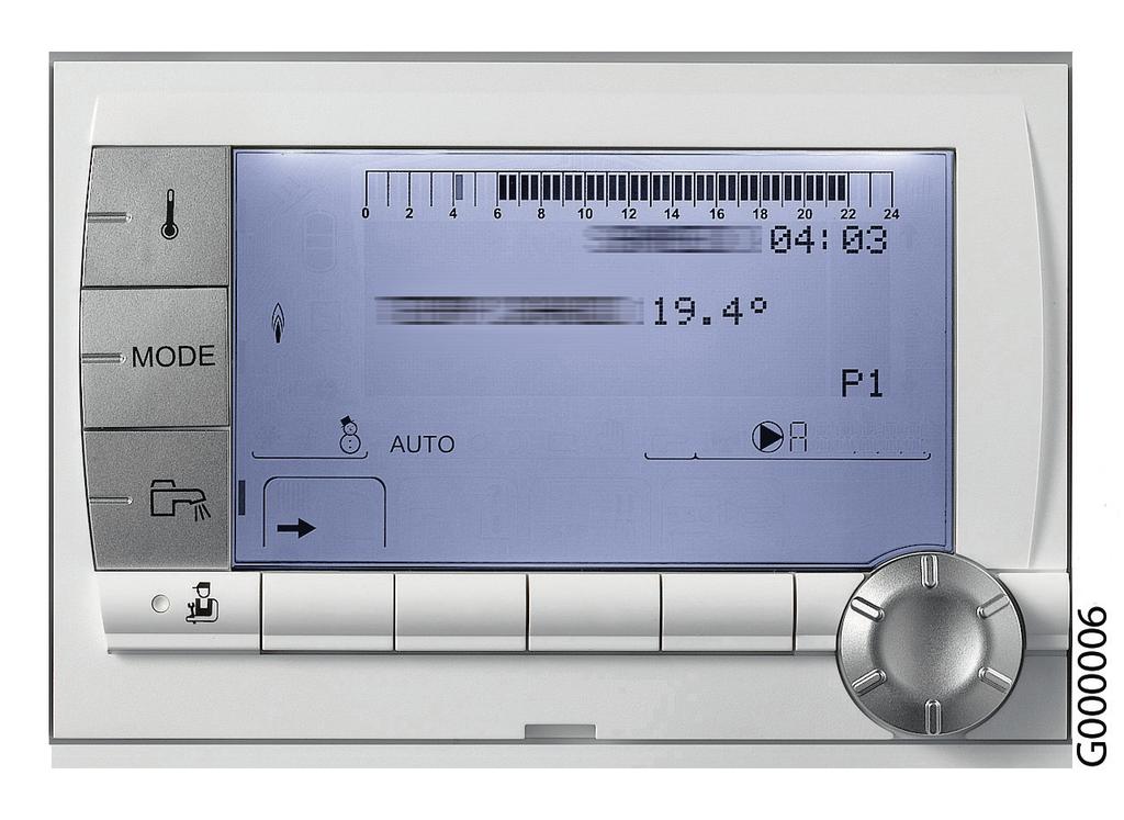
8 2. Description of the keys and the display A G0000-A I B G bar AUTO H C STD D E F A B C D E F G H I Temperature setting key (heating, DHW, swimming pool) Operating mode selection key DHW override key Key to access the parameters reserved for the installer Keys on which the function varies as and when selections are made Rotary setting button and push button: : Turn the rotary button to scroll through the menus or modify a value : Press the rotary button to access the menu selected or confirm a value modification A bar is displayed when a DHW override is activated: Flashing bar: Temporary override Steady bar: Permanent override Name of the circuit for which the parameters are displayed Timer programmes graphic display bar: Dark area : Heating period in comfort mode or DHW production enabled Light area : Heating period in reduced mode or DHW production not enabled Symbols Comfort mode: The symbol is displayed when a DAY override (comfort) is activated Flashing symbol: Temporary override Steady symbol: Permanent override Reduced mode: The symbol is displayed when a NIGHT override (reduced) is activated Flashing symbol: Temporary override Steady symbol: Permanent override Holiday mode: The symbol is displayed when a HOLIDAY override (antifreeze) is activated Flashing symbol: Holiday mode programmed Steady symbol: Holiday mode active Manual mode The symbol is displayed when domestic hot water production is running Valve indicator: The symbol is displayed when a 3-way valve is connected : Opening the 3-way valve : Closing the 3-way valve The symbol is displayed when the pump is operating Access to the various menus Used to scroll through the menus Used to scroll through the parameters Used to display the curve of the parameter selected? The symbol is displayed when help is available STD Reset of all time programmes / Comfort/reduced selection or selection of the days to be programmed Back to the previous level ESC Back to the previous level without saving the modifications made Manual reset Arrows are displayed when lines are masked higher or lower in the list. Both arrows flash when it is possible to modify a value. Flame status Pressure indicator: The symbol is displayed when a water pressure sensor is connected Flashing symbol: The quantity of water is insufficient Steady symbol: The quantity of water is sufficient. Water pressure level: : 0,9 to, bar :,2 to,5 bar :,6 to,9 bar : 2,0 to 2,3 bar : > 2,4 bar Summer mode: Reheating the domestic hot water remains ensured WINTER mode: Heating and domestic hot water working AUTO Operation in automatic mode according to the timer programme 8

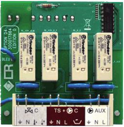
9 3. Options for the DIEMATIC isystem control panel Domestic hot water sensor - Package AD22 The DHW sensor is used for the priority control of the temperature and the programming of domestic hot water production by an accumulation tank. Outlet sensor after 3-way valve - Package AD99 This sensor is needed to connect the first circuit with mixing valve to a boiler equipped with the DIEMATIC isystem control panel. PCB + sensor for a mixing valve - Package AD249 The PCB + sensor option is used to command a mixing valve with electromechanical or electrothermal motor and the associated heating pump. The PCB is installed in the DIEMATIC isystem control panel and is connected using plug-in connectors. The DIEMATIC isystem control panel can accommodate PCB + sensor option. CDI4 interactive remote control - Package AD254 CDR4 interactive radio remote control module (without transmitter / radio receiver) - Package AD253 Boiler radio module (Transmitter/receiver) - Package AD252 The connection of an interactive remote control is used to override all instructions from the DIEMATIC isystem control panel from the room in which it is installed. The interactive control also enables the self-adaptivity of the heating law for the circuit concerned (one CDI4 or CDR4 per circuit). In the case of the CDR4, data is transmitted by radio waves from the point of installation to the transmitter / receiver unit (package AD252) located in the vicinity of the boiler. A simplified remote control with room sensor - Package FM52 The connection of a simplified remote control is used to override certain instructions from the DIEMATIC isystem control panel from the room in which it is installed: programme and room temperature set point override. The remote control is used to automatically adapt the heating curve on the circuit concerned (one simplified remote control per circuit). BUS connection cable (length 2 m package AD34) The BUS cable is used to interconnect two boilers equipped with the DIEMATIC isystem control panel in a cascade installation and to connect a DIEMATIC VM control system or a transmitter from a remote management network. Sensor for storage tank - Package AD250 Includes sensor for managing a storage tank with a boiler equipped with a DIEMATIC isystem control panel. 9


10 Outside radio-controlled temperature sensor - Package AD25 Boiler radio module (Transmitter/receiver) - Package AD252 The radio-controlled outside temperature sensor is available as an option for systems in which the installation of the wire-controlled outside temperature sensor delivered with the DIEMATIC isystem control panel turns out to be too complex. If this sensor is used with a wire-controlled remote control (AD254 or FM52), the boiler radio module (package AD252) is also needed. If a boiler radio module is already connected to the DIEMATIC isystem control panel, it is not necessary to order a second one. TELCOM voice remote monitoring module - Package AD52 Intended for the control of heating installations by phone, the module handles 2 functions:. To inform the user or a person of his choice (4 phone numbers can be programmed) if there are problems with the installation (no mains voltage, burner defect or external alarm) 2. To enable the user to remotely manage the boiler operating mode and two other circuits (e.g.: water heater). This module is recommended particularly for second homes, temporarily unoccupied main homes (holidays, etc.), and small collective systems. The TELCOM works with all telephones with voice-frequency type dialling on both land lines and mobiles (GSM). Moreover, it comprises a function enabling use with a fax or a phone answering machine, provided that it can be programmed to pick up after the third ring. 0
11
12 2
13 OPERATING PRINCIPLE 2 3
14 CONTENTS. General description Description and operation Description of the control equipments - Abbreviations Description of the BUS Functional links
15 . General description The DIEMATIC isystem control panel is an electronic regulator which can be programmed, and ensures the following functions: - Boiler temperature control via the modulating burner (in the case of the MCA wall-hung boiler) according to the outside temperature and, if applicable, the room temperature if a CDI4, CDR4 or simplified interactive remote control (available as optional equipment) is connected, - Command and control of a direct circuit without mixing valve - Command and control of a first circuit with mixing valve, with the flow sensor option (Option package AD99), - Command and control of a second mixing valve circuit, with the PCB + flow sensor option (Option package AD249). Nota: Each of these 3 heating circuits can be equipped with a CDI4, CDR4 or simplified FM52 remote control (Options). - Programming and priority control of a DHW circuit, with DHW sensor option (Package AD22), - Anti-freeze protection for the installation and the environment if the home is empty - 2 to 0 boilers can be connected in a cascade, - Option of connecting to 0 DIEMATIC VM control systems - Management of systems combining various heating generators (boiler + heat pump or boiler + solar system ) This allows the installer to set the parameters for the heating system as a whole. 2 5
16 2. Description and operation 2. Description of the control equipments - Abbreviations PCU: Primary Control Unit - PCB for managing burner operation. The parameters for the PCU board are displayed in specific menus: #PRIMARY LIMITS and #PRIMARY INSTAL.P. Messages from the PCU board have a code that starts with Bxx. Defects on the PCU board have a code that starts with Lxx. PSU : Parameter Storage Unit - Parameter storage for PCBs PCU and SU. If a PCU or SU board is replaced, it is not necessary to reset the parameters displayed in the #PRIMARY LIMITS and #PRIMARY INSTAL.P menus. These settings are memorised in the PSU board. If the PSU board is replaced, the parameter settings for the #PRIMARY LIMITS and #PRIMARY INSTAL.P menus should be done again. The PSU is electrically connected to the PCU but the communication link is also made between PSU and SU. SCU: Secondary Control Unit - DIEMATIC isystem control panel PCB. This board pilots all secondary systems (circuits A, B, C, DHW and AUX) and sends the summary of demands on these circuits to the PCU via the PCU bus. SU : Safety Unit - Safety PCB (Safety box). CDI4: Interactive wire-controlled remote control with LCD display. CDR4: Interactive radio remote control with LCD display. FM52: Simplified remote control MCR4 : Boiler radio module HMI: Display (Human Machine Interface) IOBL: Carrier current home automation bus Description of the BUS CDI bus: handles the link between the remote controls and the boiler Cascade bus: handles the links in the cascade (DIEMATIC VM regulator, TELCOM telemanagement transmitter) PCU bus: used to communicate with the PCU board : DIEMATIC isystem to PCU: - Burner on/off command - Boiler set point temperature - Output capping PCU to DIEMATIC isystem: - Measurements - Faults (Lxx) / Messages(Bxx) - present states (Pump, Gas valve, Flame status,...) - Parameters IOBL bus (In One By Legrand): Communication on carrier current (works with In One By Legrand products...). 6
 - DHW tank temperature (BIC) - Boiler temperature - Return temperature - Ionisation measurement - Safety thermostat G00000 PCU")
 -")

17 2.3 Functional links PRIMARY (Boiler) SECONDARY (Installation) Pump A Pump B HW. PUMP OP. 3WV B CL. 3WV B TEL.OUTPUT - Input BL - Fan speed - Flow switch (MI) - DHW tank temperature (BIC) - Boiler temperature - Return temperature - Ionisation measurement - Safety thermostat G00000 PCU Generator control SU - Safety - Gas bus PSU - Boiler pump (ON/OFF + modulation - DHW reversal valve - Fan control - BIC: DHW load pump - Gas valve - Ignition transformer PCU bus - DHW sensor - Outside sensor - Outlet sensor B - Outlet sensor C - A ROOM sensor - B ROOM sensor - C ROOM sensor - TAS - System sensor - TEL INPUT SCU-C (DIEMATIC isystem) - Piloting the PCU - Direct circuit A - Circuit B - Circuit C - DHW circuit - DHW ELEC - Auxiliary circuit - Cascade - Pool - high temperature heating circuit - Buffer tank CDI bus Cascade bus HMIdisplay valve option PCB AD249 Pump C BOILER P. OP. 3WV C CL. 3WV C 3 CDI4 / FM52 or MCR4 - Boilers (Cascade) - DIEMATIC VM - Teleprocessing transmitter Location of the boards AD249* SCU G PCU PSU SU HMI * Board for 3-way-valve (option) 7
18 2 8

19 CONFIGURATION OF THE CIRCUITS 3 G
20 CONTENTS Installation and connection examples. Safety instructions Configuration to be done beforehand Connecting a direct circuit Connecting a direct heating circuit and a domestic hot water tank Connecting two circuits and a domestic hot water tank before the mixing tank Connecting two circuits and a domestic hot water tank after the mixing tank Hot water storage tank connection QUADRO DU type storage tank PS type storage tank and DHW tank loaded by the boiler PS type storage tank and DHW tank loaded by this storage tank Pool connection Connecting a mixed tank (DHW) Connecting the options Connection in cascade Cascade management principle Possible checks (on the "master" boiler) Parameter settings in the case of a cascade installation DHW tank after the mixing tank DHW tank on "master" boiler
21 . Safety instructions CAUTION When working on the boiler, always disconnect the boiler from the mains and close the main gas inlet valve. After maintenance or repair work, check all installations to ensure that there are no leaks. The mains supply is made via the cable C connected to the mains. All other external connections are done on the connection connectors (low voltage). The main characteristics of the control unit are described in the table below: Power supply voltage Rating of the main fuse F (230 VAC) Fuse rating F2 (230 VAC) Fan-DC 230 VAC/50 Hz 6.3 AT 2 AT 24 VDC C A Routing of the 230 V cables B Routing of the sensor cables C Power supply cable D 6.3 AT fuse E 2AT fuse D E A B C E CAUTION The following components of the appliance are at a voltage of 230 V: - Boiler pump - Combined gas valve unit - Inverter valve - The majority of components in the control panel and the terminal box - Power supply cable 3 2
22 2. Configuration to be done beforehand. To access all parameters: first set the INSTALLATION parameter to EXTENDED. In CLASSIC mode, only the parameters for a classic installation are displayed. The regulator automatically switches back to CLASSIC mode after 30 minutes (whether or not a key has been pressed). Press Display Select Display Press Display Installer access for 5 sec. #LANGUAGE #SYSTEM #NAMES OF THE CIRCUITS #... #SYSTEM INSTALLATION CLASSIC Press the rotary button Turn the rotary button to select the parameter: INSTALLATION EXTENDED Press the rotary button to confirm INSTALLATION EXTENDED 2. To control and adapt all parameters according to the type of installation: the following chapters give the connections and parameter settings to be made. 3 22
23 3. Connecting a direct circuit SCU PCU On/off 0-0V S AMB C S AMB B S AMB A OT BL RL Tout Tdhw 4 B TS + B A S SYST + TA - S ECS S EXT S DEP C S DEP B G M 3 Diagram: Not used: Do not connect anything to the terminal block. Connect the outside temperature sensor. Connect a safety thermostat if the heating circuit is for underfloor heating. Remove the bridge. Connect the wires from the safety thermostat to the connector. Not used: Do not connect anything to the terminal block. Parameter settings to be made for this type of installation: If underfloor heating is connected directly (without mixing valve), set the parameter IN.BL as follows: Press Display Select Display Select Display Select Installer access #LANGUAGE #PRIMARY INSTAL.P BURN.MIN.RUN () IN.BL STOP HEAT STOP HEAT #SYSTEM TIMER GENE P. TOTAL STOP #... IN.BL SAFETY MODE for 5 sec. #PRIMARY INSTAL.P Configuration of the outlets should not be modified; the factory setting below is suitable: Parameter Factory setting Access: Menu Select Remarks CIRC. A: () DIRECT "Installer" level #SYSTEM CIRC. A: () Keep the factory setting 3 () The parameter is only displayed if INSTALLATION parameter is set to EXTENDED. To switch to EXTENDED mode : See page 22. The factory presetting of the other parameters used in this type of installation is suitable but can be customised if necessary (See table below): Parameter Factory setting Access: Menu Select Remarks CIRC.CURVE A,5 "Installer" level #SECONDARY INSTAL.P... CIRC.CURVE A If circuit A is for underfloor heating, set the value to 0.7. For more detailed information on the parameters: See section 4. 23
24 4. Connecting a direct heating circuit and a domestic hot water tank SCU PCU On/off 0-0V S AMB C S AMB B S AMB A OT BL RL Tout Tdhw 8 2 B TS + B A S SYST + TA - S ECS S EXT S DEP C S DEP B G M Diagram: Not used: Do not connect anything to the terminal block. CAUTION: Do not connect anything to the DHW pump outlet as the reversal valve is connected to the PCU PCB in the boiler Connect the outside temperature sensor. Connect a safety thermostat if the heating circuit is for underfloor heating. Remove the bridge. Connect the wires from the safety thermostat to the connector in the position marked BL, after first removing the bridge. Connect the DHW tank anode. CAUTION: If the tank is fitted with a Titan Active System impressed current anode, connect the anode to the inlet (+ on the anode, - on the tank). If the tank is not fitted with an impressed current anode, put the simulation connector in place (delivered with the DHW sensor - package AD22) Connect the DHW sensor (Package AD22). Connect the domestic hot water looping pump (Optional). Not used: Do not connect anything to the terminal block. 24
25 Parameter settings to be made for this type of installation: Press Display Select Display Select Display Select Installer access #LANGUAGE #SYSTEM #... #PRIMARY INSTAL.P Parameter settings for IN.BL to connect the TS to an underfloor heating system #PRIMARY INSTAL.P BURN.MIN.RUN () TIMER GENE P. IN.BL Parameter settings for the DHW loop IN.BL STOP HEAT TOTAL STOP SAFETY MODE TOTAL STOP for 5 sec. #SYSTEM INSTALLATION CIRC. A: ()... O.PUMP A () O.PUMP A ()... CH.PUMP A... DHW LOOP... DHW LOOP Configuration of the outlets should not be modified; the factory setting below is suitable: Parameter Factory setting Access: Menu Select Remarks CIRC. A: () DIRECT "Installer" level #SYSTEM CIRC. A: () Keep the factory setting () The parameter is only displayed if INSTALLATION parameter is set to EXTENDED. To switch to EXTENDED mode : See page 22. The factory presetting of the other parameters used in this type of installation is suitable but can be customised if necessary (See table below): Parameter Factory setting Access: Menu Select Remarks CIRC.CURVE A,5 "Installer" level #SECONDARY INSTAL.P... CIRC.CURVE A If circuit A is for underfloor heating, set the value to 0.7. For more detailed information on the parameters: See section
26 5. Connecting two circuits and a domestic hot water tank before the mixing tank AD249 SCU PCU C TS + C AUX On/off 0-0V S AMB C S AMB B S AMB A OT BL RL Tout Tdhw 3 2 B TS + B A 7 S SYST + TA - S ECS S EXT S DEP C S DEP B G00006A 3 M Diagram: Not used: Do not connect anything to the terminal block. CAUTION: Do not connect anything to the DHW pump outlet as the reversal valve is connected to the PCU PCB in the boiler Connect the outside temperature sensor. Connect the heating pump (circuit A) Nota : If underfloor heating is being used, put a safety thermostat in place after the heating pump. Remove the bridge. Connect the wires from the safety thermostat to the connector in the position marked BL, after first removing the bridge. The safety thermostat will shut down the heating pump in the event of overheating. Connect the 3-way valve motor (circuit B) and the circuit B flow sensor (FL S B). Connect the heating pump (circuit B). Connect a safety thermostat if the heating circuit is for underfloor heating: Remove the bridge. Connect the wires from the safety thermostat to the connector. Low loss header. Connect the DHW sensor (Package AD22). 26
27 Connect the domestic hot water loop pump (optional) to the S.AUX outlet on the PCB option for mixing valve (Option: Package AD249). Connection of an additional circuit, with PCB option for mixing valve (Option: Package AD249). Connect the DHW tank anode. CAUTION: If the tank is fitted with a Titan Active System impressed current anode, connect the anode to the inlet (+ on the anode, - on the tank). If the tank is not fitted with an impressed current anode, put the simulation connector in place (delivered with the DHW sensor - package AD22) Not used: Do not connect anything to the terminal block. Parameter settings to be made for this type of installation: Configuration of the outlets should not be modified; the factory settings below are suitable. Parameter Factory setting Access: Menu Select Remarks CIRC. A: () DIRECT "Installer" level #SYSTEM CIRC. A: () CIRC. B: () 3WV "Installer" level #SYSTEM CIRC. B: () O.PUMP A () CH.PUMP A "Installer" level #SYSTEM O.PUMP A () O.DHW: () RV "Installer" level #SYSTEM O.DHW: () S.AUX: () DHW LOOP "Installer" level #SYSTEM S.AUX: () Keep the factory setting () The parameter is only displayed if INSTALLATION parameter is set to EXTENDED. To switch to EXTENDED mode : See page 22. The factory presetting of the other parameters used in this type of installation is suitable but can be customised if necessary (See table below): Parameter Factory setting Access: Menu Select Remarks "Installer" level #SECONDARY INSTAL.P... CIRC.CURVE A If circuit A is for CIRC.CURVE A,5 underfloor heating, set the value to 0.7. CIRC.CURVE B 0,7 "Installer" level #SECONDARY INSTAL.P... CIRC.CURVE B For more detailed information on the parameters: See section
28 6. Connecting two circuits and a domestic hot water tank after the mixing tank AD249 SCU PCU C TS + C AUX On/off 0-0V S AMB C S AMB B S AMB A OT BL RL Tout Tdhw 2 B TS + B A 5 S SYST + TA - S ECS S EXT S DEP C S DEP B G000042A M Diagram: Not used: Do not connect anything to the terminal block. Connect the outside temperature sensor. Connect the heating pump (circuit A) Nota : If underfloor heating is being used, put a safety thermostat in place after the heating pump. Remove the bridge. Connect the wires from the safety thermostat to the connector in the position marked BL, after first removing the bridge. The safety thermostat will shut down the heating pump in the event of overheating. Connect the heating pump (circuit B). Connect the 3-way valve motor. Connect the safety thermostat for the underfloor heating. Remove the bridge. Connect the wires from the safety thermostat to the connector. Low loss header. Connect the DHW tank load pump. Connect the DHW sensor (Package AD22). Connect the DHW tank anode. CAUTION: If the tank is fitted with a Titan Active System impressed current anode, connect the anode to the inlet (+ on the anode, - on the tank). 28
29 If the tank is not fitted with an impressed current anode, put the simulation connector in place (delivered with the DHW sensor - package AD22). Connect the domestic hot water loop pump (optional) to the S.AUX outlet on the PCB option for mixing valve (Package AD249). Connection of an additional circuit, with PCB option for mixing valve (Package AD249). Not used: Do not connect anything to the terminal block. Parameter settings to be made for this type of installation: Press Display Select Display Select Display Select Installer access #LANGUAGE #SYSTEM INSTALLATION O.DHW: () PUMP PUMP #SYSTEM CIRC. A: () RV # for 5 sec. O.DHW: () Configuration of the outlets should not be modified; the factory settings below are suitable: Parameter Factory setting Access: Menu Select Remarks CIRC. B: () 3WV "Installer" level #SYSTEM CIRC. B: () Keep the factory CIRC. A: () DIRECT "Installer" level #SYSTEM CIRC. A: () O.PUMP A () CH.PUMP A "Installer" level #SYSTEM O.PUMP A () setting S.AUX: () DHW LOOP "Installer" level #SYSTEM S.AUX: () () The parameter is only displayed if INSTALLATION parameter is set to EXTENDED. To switch to EXTENDED mode : See page 22. The factory presetting of the other parameters used in this type of installation is suitable but can be customised if necessary (See table below): Parameter Factory setting Access: Menu Select Remarks CIRC.CURVE A,5 "Installer" level #SECONDARY INSTAL.P... CIRC.CURVE A If circuit A is for underfloor heating, set the value to 0.7. CIRC.CURVE B 0,7 "Installer" level #SECONDARY INSTAL.P... CIRC.CURVE B For more detailed information on the parameters: See section

30 7. Hot water storage tank connection 7. QUADRO DU type storage tank In this installation example, the storage tank (type QUADRO DU) incorporates a domestic hot water zone. The boiler starts up systematically to maintain the domestic hot water zone in the storage tank at temperature. SCU PCU On/off 0-0V S AMB C S AMB B S AMB A OT BL RL Tout Tdhw 8 9 B TS + B A S SYST + TA - S ECS S EXT S DEP C S DEP B G000043B M 3 5 Diagram: Connect the heating pump (circuit A) Connect the DHW tank anode. CAUTION: If the tank is not fitted with an impressed current anode, put the simulation connector in place (delivered with the DHW sensor - package AD22) Connect the DHW sensor (Package AD22). Connect the sensor from the storage tank (Package AD250). Buffer tank (Type QUADRO). Solar sensor probe. Connect the solar control system. Not used: Do not connect anything to the terminal block. Not used: Do not connect anything to the terminal block. 30
31 Operating principle The DHW part is maintained at the DHW set point by the boiler. The heating zone is maintained at the set temperature calculated according to the outside temperature. The zone is reheated when the heating buffer temperature sensor falls -6 C below the calculated set temperature. Reheating in the heating zone stops when the heating buffer temperature rises above the calculated set temperature. Parameter settings to be made for this type of installation: Press Display Select Display Select Display Select Installer access for 5 sec. #LANGUAGE #SYSTEM #... #PRIMARY INSTAL.P #SYSTEM INSTALLATION... O.DHW: ()... I.SYST ()... O.DHW: () I.SYST () PUMP RV SYSTEM STORAGE TANK DHW STRAT ST.TANK+DHW PUMP STORAGE TANK Configuration of the outlets should not be modified; the factory settings below are suitable: Parameter Factory setting Access: Menu Select Remarks CIRC. A: () DIRECT "Installer" level #SYSTEM CIRC. A: () Keep the factory O.PUMP A () CH.PUMP A "Installer" level #SYSTEM O.PUMP A () setting () The parameter is only displayed if INSTALLATION parameter is set to EXTENDED. To switch to EXTENDED mode : See page 22. The factory presetting of the other parameters used in this type of installation is suitable but can be customised if necessary (See table below): Parameter Factory setting Access: Menu Select Remarks CIRC.CURVE A,5 "Installer" level #SECONDARY INSTAL.P... CIRC.CURVE A For more detailed information on the parameters: See section
32 7.2 PS type storage tank and DHW tank loaded by the boiler The boiler starts up systematically to maintain the storage tank or the DHW tank at temperature. SCU PCU On/off 0-0V S AMB C S AMB B S AMB A OT BL RL Tout Tdhw 9 0 B TS + B A S SYST + TA - S ECS S EXT S DEP C S DEP B G000030A M 3 Diagram: Connect a domestic hot water tank if the storage tank is only used for heating. Connect the DHW sensor (Package AD22). Connect the heating pump (circuit A) Buffer tank. Connect the sensor from the storage tank (Package AD250). Solar sensor probe. Connect the solar control system. Connect the DHW tank anode. CAUTION: If the tank is fitted with a Titan Active System impressed current anode, connect the anode to the inlet (+ on the anode, - on the tank). If the tank is not fitted with an impressed current anode, put the simulation connector in place (delivered with the DHW sensor - package AD22). Not used: Do not connect anything to the terminal block. Not used: Do not connect anything to the terminal block. 32
33 Operating principle The storage tank is maintained at the DHW set point by the boiler. The storage tank is maintained at the set point calculated as a function of the outside temperature. The storage tank is reheated when the heating storage temperature sensor falls below the set point calculated -6 C. Reheating of the storage tank stops when the heating storage temperature falls below the boiler set point calculated. Parameter settings to be made for this type of installation: Press Display Select Display Select Display Select Installer access #LANGUAGE #SYSTEM INSTALLATION I.SYST () SYSTEM STORAGE STORAGE TANK #SYSTEM... TANK #... I.SYST () DHW STRAT #PRIMARY INSTAL.P ST.TANK+DHW for 5 sec. Configuration of the outlets should not be modified; the factory settings below are suitable ; Parameter Factory setting Access: Menu Select Remarks CIRC. A: () DIRECT "Installer" level #SYSTEM CIRC. A: () Keep the factory O.PUMP A () CH.PUMP A "Installer" level #SYSTEM O.PUMP A () setting O.DHW: () RV "Installer" level #SYSTEM O.DHW: () () The parameter is only displayed if INSTALLATION parameter is set to EXTENDED. To switch to EXTENDED mode : See page 22. The factory presetting of the other parameters used in this type of installation is suitable but can be customised if necessary (See table below): Parameter Factory setting Access: Menu Select Remarks CIRC.CURVE A,5 "Installer" level #SECONDARY INSTAL.P... CIRC.CURVE A Adjust if necessary For more detailed information on the parameters: See section
34 7.3 PS type storage tank and DHW tank loaded by this storage tank The boiler only starts up production of domestic hot water if the storage tank is not hot enough to guarantee tank loading. SCU PCU On/off 0-0V S AMB C S AMB B S AMB A OT BL RL Tout Tdhw 0 B TS + B A S SYST + TA - S ECS S EXT S DEP C S DEP B G000044A M 5 3 Diagram: Connect the heating pump (circuit A). Connect the sensor from the storage tank (Package AD250) Buffer tank (Type PS) Domestic hot water boiler Connect the DHW sensor. Connect the DHW tank load pump Connect the DHW tank anode. CAUTION: If the tank is fitted with a Titan Active System impressed current anode, connect the anode to the inlet (+ on the anode, - on the tank). If the tank is not fitted with an impressed current anode, put the simulation connector in place (delivered with the DHW sensor - package AD22). Solar sensor probe. Connect the solar control system. Not used: Do not connect anything to the terminal block. Not used: Do not connect anything to the terminal block. 34
35 Operating principle The DHW tank is loaded from the storage tank. If, during DHW loading, the temperature of the storage tank falls below the primary DHW set point, the boiler maintains the latter at temperature to guarantee loading of the DHW tank. The storage tank is maintained at the set point calculated as a function of the outside temperature. The storage tank is reheated when the heating storage temperature sensor falls below the set point calculated -6 C. Reheating of the storage tank stops when the heating storage temperature falls below the boiler set point calculated. Parameter settings to be made for this type of installation: Press Display Select Display Select Display Select Installer access #LANGUAGE #SYSTEM #... #PRIMARY INSTAL.P Parameter settings for I.SYST for connecting the storage tank sensor #SYSTEM INSTALLATION I.SYST () SYSTEM I.SYST () DHW STRAT... ST.TANK+DHW ST.TANK+DHW Parameter settings for P.DHW for connecting the DHW tank load pump for 5 sec. #SYSTEM INSTALLATION... O.DHW: ()... O.DHW: () PUMP RV PUMP Configuration of the outlets should not be modified; the factory setting below is suitable: Parameter Factory setting Access: Menu Select Remarks CIRC. A: () DIRECT "Installer" level #SYSTEM CIRC. A: () Keep the factory setting () The parameter is only displayed if INSTALLATION parameter is set to EXTENDED. To switch to EXTENDED mode : See page 22. The factory presetting of the other parameters used in this type of installation is suitable but can be customised if necessary (See table below): Parameter Factory setting Access: Menu Select Remarks CIRC.CURVE A,5 "Installer" level #SECONDARY INSTAL.P... CIRC.CURVE A 3 For more detailed information on the parameters: See section 4. 35
36 8. Pool connection SCU PCU On/off 0-0V S AMB C S AMB B S AMB A OT BL RL Tout Tdhw 6 0 B TS + B A S SYST + TA - S ECS S EXT S DEP C S DEP B G Diagram: Connect the secondary swimming pool pump. Remark: if the pump is also used for filtration, fit a bypass to the filter. Connect the swimming pool sensor. Plate heat exchanger. Pool heating cut-off control. When the parameter I.TEL: is on 0/ B, the swimming pool is no longer heated when the contact is open (factory setting), only the antifreeze continues to be active. The contact direction can still be adjusted by the parameter CT.TEL. Connect the primary swimming pool pump. Not used: Do not connect anything to the terminal block. Not used: Do not connect anything to the terminal block. 36
37 Parameter settings to be made for this type of installation: Press Display Select Display Select Display Select Installer access for 5 sec. #LANGUAGE #SYSTEM #... #PRIMARY INSTAL.P #... #... #... #SECONDARY LIMITS #... Parameter settings for CIRC. B: for connecting the primary swimming pool pump: #SYSTEM INSTALLATION... CIRC. B: ()... CIRC. B: () 3WV SWIM.P. DIRECT SWIM.P. Parameter settings for I.TEL: for controlling swimming pool heating shutdown: #SYSTEM INSTALLATION... CIRC. B:()... I.TEL: () I.TEL: () ANTIFR... 0/ B... 0/ B (2) Parameter settings for the temperature MAX. CIRC. B for the needs of the swimming pool exchanger: #SECONDARY LIMITS MAX. CIRC. A MAX. CIRC. B... MAX. CIRC. B 50 C Value to be set () The parameter is only displayed if INSTALLATION parameter is set to EXTENDED. To switch to EXTENDED mode : See page 22. (2) See section 4, Parameter: 0/ B Controlling the pool circuit The control system can be used to manage a swimming pool circuit in both cases: Case : The control system regulates the primary circuit (boiler/exchanger) and the secondary circuit (exchanger/pool). Connect the primary circuit pump (boiler/exchanger) to the pump B outlet. The temperature MAX.CIRC.B is then guaranteed during comfort periods on programme B in summer and winter alike. Connect the pool sensor (package AD22) to the S OUTL B input. Set the swimming pool sensor set point using key in the range 5 to 39 C. Case 2: The pool has already a regulation system that is to be kept. The control system only regulates the primary circuit (boiler/exchanger). Connect the primary circuit pump (boiler/exchanger) to the pump B outlet. The temperature MAX.CIRC.B is then guaranteed during comfort periods on programme B in summer and winter alike. 3 Hourly programming of the secondary circuit pump The secondary pump operates during programme B comfort periods in summer and winter alike. Stopping To prepare your pool for winter, consult your pool specialist. It is also possible to connect the swimming pool to circuit C by adding the PCB + flow sensor option (Package AD249). Make the connection to the terminal blocks marked C. Set the parameters for circuit C. 37
38 9. Connecting a mixed tank (DHW) AD249 SCU PCU C TS + C AUX On/off 2 0-0V S AMB C S AMB B S AMB A OT BL RL Tout Tdhw 7 B TS + B A 3 S SYST + TA - S ECS S EXT S DEP C S DEP B G00006A 8 6 M Diagram: Not used: Do not connect anything to the terminal block. Auxiliary outlet - Option of connecting the electric DHW tank with the PCB + flow sensor option (package AD249) or to (circuit A). Option of connecting the electric tank: Outlet circuit A, or to ). Power control relay to the electrical resistor. Connect the DHW sensor (Package AD22). Connect the outside temperature sensor. Not used: Do not connect anything to the terminal block. Connect the DHW tank anode. CAUTION: If the tank is fitted with a Titan Active System impressed current anode, connect the anode to the inlet (+ on the anode, - on the tank). If the tank is not fitted with an impressed current anode, put the simulation connector in place (delivered with the DHW sensor - package AD22). 38
39 Parameter settings to be made for this type of installation: Press Display Select Display Select Display Select Installer access for 5 sec. #LANGUAGE #SYSTEM #... #PRIMARY INSTAL.P #SYSTEM INSTALLATION CIRC. A: ()... S.AUX: ()... CIRC. A: () or S.AUX: () DIRECT... DHW ELEC DHW LOOP... DHW ELEC DHW ELEC DHW ELEC () The parameter is only displayed if INSTALLATION parameter is set to EXTENDED. To switch to EXTENDED mode : See page 22. For more detailed information on the parameters: See section
40 TELCOM 2 AL 2 AL2 PRG 3 ALP # V V SET 0.Connecting the options For example: TELCOM remote vocal monitoring module, remote controls for circuits A and B, second DHW tank. AD249 SCU PCU G C TS + C AUX On/off 0-0V S AMB C S AMB B S AMB A OT BL RL Tout Tdhw B TS + B A 5 S SYST + TA - S ECS S EXT S DEP C S 2 DEP B * x c MODE r x c MODE r 3 Diagram: Not used: Do not connect anything to the terminal block. Connect the load pump to the second tank. Second domestic hot water tank. Connect the DHW sensor from the second tank. Alarm indicator. Connect the TELCOM remote vocal monitoring module - depending on its availability in your country. See diagram next page. Connecting the BUS cascade, VM. Connect the remote control(s) (Package AD254/FM52)) Not used: Do not connect anything to the terminal block. Parameter settings to be made for this type of installation: Press Display Select Display Select Display Select Installer access #LANGUAGE Parameter settings for S.AUX: for connecting a second DHW tank: #SYSTEM #... #SYSTEM S.AUX: () DHW #PRIMARY INSTAL.P for 5 sec. INSTALLATION... S.AUX: ()... Parameter settings for O.PUMP A for alarm report : #SYSTEM INSTALLATION... O.PUMP A ()... O.PUMP A () DHW LOOP... DHW... CH.PUMP A... FAILURE FAILURE () The parameter is only displayed if INSTALLATION parameter is set to EXTENDED. To switch to EXTENDED mode : See page
41 Connecting the TELCOM vocal telesurveillance module AD249 C TS + C AUX SCU 2 0-0V S AMB C S AMB B S AMB A B TS + B A S SYST + TA - S ECS S EXT S DEP C S 2 DEP B G V dc 230 V ac V AL AL2 ALP V TELCOM 2 PRG * 9 0 # SET 2 3 NO C NC NO C NC NO C NC N (230 V) L Power supply 230 V AC +0%/-5% The telephone outlet, terminals 3 and 4, is a potential-free relay, limited to 24 V. Not used: Do not connect anything to the terminal block. 3 4
42 .Connection in cascade. Cascade management principle The DIEMATIC isystem control panel can control up to 0 boilers in cascade and manage 0 DIEMATIC VM regulators. - the common flow temperature sensor (TEMP.SYSTEM parameter) is connected to the S.SYST inlet on the master boiler (number ) - a single outside temperature sensor can be connected to the master boiler or one sensor per boiler (zone control system) can be connected. - the control panels are interconnected using bus cables, - the 3-way valve circuits in the boilers in the cascade are operable. - the flow set point is common to all boilers in the cascade. To form the cascade, set the corresponding parameters in the #NETWORK menu (CASCADE, MASTER CONTROLLER, etc.) for each of the boilers and DIEMATIC VM control system(s) in the cascade as described below. With the factory settings (FUNCT parameter on CLASSIC), the boilers automatically swap every 7 days (a new boiler becomes the master) It is also possible to swap the boilers manually: in the #SETTING menu, set the PERMUT parameter to the number of the boiler to remain in charge of the cascade. The (primary) pump for the boilers is started up whenever a burner demand is present and is stopped after the time delay TIMER GENE P. when the burner demand disappears. The primary pump on the master boiler continues to operate as long as a heating demand is present on one of the secondary circuits. Operating mode if the FUNCT parameter is set to PARALLEL: If the FUNCT parameter is set to PARALLEL and the outside temperature is lower than the PARALLEL.CASC set point (factory setting: 0 C), all boilers are started up simultaneously when there is a heating demand. If the outside temperature is higher than the PARALLEL.CASC set point, operation is identical to a CLASSIC cascade. 3 Operating mode if the FUNCT parameter is set to CLASSIC: A boiler is added to the cascade when the common flow temperature falls below the set point less 3 C if no boilers are in demand. Every 4 minutes (or period equal to the parameter setting INTER STAGE TIMER, factory setting = 4 minutes), the control system analyses the variation in the common flow temperature. If this temperature has not increased by more than 6 C in this period of time and the common flow temperature is still lower than the set point by 3 C, a further boiler is added. Regardless of the setting of the FUNCT parameter (CLASSIC or PARALLEL): A boiler is removed when the common outlet temperature rises +3 C above the set temperature. Every 4 minutes (or period equal to the parameter setting INTER STAGE TIMER, factory setting = 4 minutes), the control system analyses the variation in the common flow temperature. If this common flow temperature has not fallen by more than 6 C and the common flow temperature is still higher than the set point by 3 C, a boiler is removed from the cascade. 42
43 Correcting the set point temperature: The boiler set point temperature (CALC.T. BOILER) is corrected to factor in any variation in temperature due to the mixture in the pressure release cylinder: CALC.T. BOILER = CALC.T.CASC + Correction Correction = CALC.T.CASC - SYSTEM TEMP. (correction limited to +0 / -0 C) WITHOUT CORRECTION WITH CORRECTION 50 C 50 C SYSTEM TEMP. 45 C 55 C 55 C SYSTEM TEMP. = 50 C CALC.T.CASC. 50 C CALC.T.CASC. = 50 C 30 C 30 C G000066A G000067A For example: Deposit = 50 C SYSTEM TEMP. = 45 C Correction = = 5 C CALC.T. BOILER = = 55 C.2 Possible checks (on the "master" boiler) Access the "After Sales" level, Display menu #PARAMETERS: Display the following parameters regarding the cascade: PERMUT NB.CASC.: NB. VM: STAGE Number of the active master boiler (cascade pilot). Number of boilers recognised in the cascade. Used to check the correct parameter setting of the generators in the cascade. Used to check the correct connection of the bus cables. Number of DIEMATIC VM control systems recognised in the cascade Number of boilers operating or in demand. 3 43
44 .3 Parameter settings in the case of a cascade installation 4 5 M BUS M 2 M 3 "Master" boiler "Auxiliary" boiler, no. 2 "Auxiliary" boiler, no. 3 DIEMATIC VM, no. 20 "auxiliary". DIEMATIC VM, no. 2 "auxiliary". G00003 Proceed in the following order: First set the parameters for the auxiliary boilers (numbers allocated: 2 to 9), Set parameters for the DIEMATIC VMs (numbers allocated: 20 to 39) if need be, Set the parameters for the "master" boiler (number allocated: ). Proceed as follows: 3 44
45 Parameter settings to be made: Press Display Select Display Select Display Select Cascade parameter settings on each of the "AUXILIARY" boilers: Installer access for 5 sec. #LANGUAGE #SYSTEM #... #NETWORK () #... #... #NETWORK () CASCADE: MASTER CONTROLLER... SLAVE NUMBER CASCADE: MASTER CONTROLLER ON OFF ON OFF ON OFF SLAVE NUMBER 2, : Boiler 2 3 : Boiler 3 etc. Cascade parameter settings on each DIEMATIC VM ("auxiliary".) See the instructions supplied with the control unit and any remote control unit used Cascade parameter settings on the "MASTER" boiler- Installer access for 5 sec. #LANGUAGE #SYSTEM #... #NETWORK () #... #... #... FUNCT PARALLEL CASC. INTER STAGE TIMER #NETWORK () CASCADE: MASTER CONTROLLER SYSTEM NETWORK... CASCADE: MASTER CONTROLLER SYSTEM NETWORK Access:#NETWORK menu (See section 4, chapter 2.4) ON OFF ON OFF NB. ELEMENTS.NETWORK ADD SLAVE ERASE NETWORK 20 : DIEMATIC VM no. 2 : DIEMATIC VM no. 2 etc. ON ON ADD SLAVE: save the numbers of the "auxiliary" appliances previously set. The number is memorised each time the rotary button is pressed. () The parameter is only displayed if INSTALLATION parameter is set to EXTENDED. To switch to EXTENDED mode : See page 22. The regulator automatically switches back to CLASSIC mode after 30 minutes (whether or not a key has been pressed). 3 45
46 .4 DHW tank after the mixing tank M M 6 6 M 7 G Diagram: "Master" boiler (number allocated = ). "Auxiliary" boiler (number allocated = 2). "Auxiliary" boiler (number allocated = 3). D.H.W. load pump. DHW sensor. Cable BUS. Low loss header. Cascade outlet sensor. Connect the sensor to the terminal block E.SYST on the master boiler. Parameter settings to be made for this type of installation: Press Display Select Display Select Display Select Installer access for 5 sec. #LANGUAGE #SYSTEM #... Parameter settings for P.DHW on the "MASTER" boiler - #SYSTEM INSTALLATION... O.DHW: ()... O.DHW: () PUMP RV PUMP Cascade parameter settings See chapter:.3 Parameter settings in the case of a cascade installation (page 44) () The parameter is only displayed if INSTALLATION parameter is set to EXTENDED. To switch to EXTENDED mode : See page 22. The regulator automatically switches back to CLASSIC mode after 30 minutes (whether or not a key has been pressed). Operating principle All of the boilers play a part in loading the DHW tank. 46
47 .5 DHW tank on "master" boiler M 6 M M 7 G00004A 4 Diagram: "Master" boiler (number allocated = ). "Auxiliary" boiler (number allocated = 2). "Auxiliary" boiler (number allocated = 3). Low loss header. Cascade outlet sensor. Connect the sensor to the terminal block E.SYST on the master boiler. Cable BUS. DHW sensor. Parameter settings to be made for this type of installation: Press Display Select Display Select Display Select Parameter settings for P.DHW on the "MASTER" boiler - Installer access for 5 sec. #LANGUAGE #SYSTEM #... #SYSTEM INSTALLATION... O.DHW: ()... O.DHW: () PUMP RV RV Cascade parameter settings See chapter:.3 Parameter settings in the case of a cascade installation (page 44) 3 () The parameter is only displayed if INSTALLATION parameter is set to EXTENDED. To switch to EXTENDED mode : See page 22. The regulator automatically switches back to CLASSIC mode after 30 minutes (whether or not a key has been pressed). Operating principle DHW tank loading is only handled by boiler. The other boilers continue to meet the heating needs. Boiler ("master") operates at high temperature whilst heating can operate at low temperature. To do this, set the PRIORITY DHW parameter to NO (#SECONDARY LIMITS menu) on boiler. 47
48 3 48
49 LIST OF THE PARAMETERS 4 G
50 Contents 4 The DIEMATIC isystem control system incorporates 3 parameter levels. User parameter level Access: Key. #MEASURES menu #CHOICE TIME PROG. menu #TIME PROGRAM menu #SETTING menu #TIME.DAY menu Access:Keys, MODE and.6 Adjusting the set point temperatures - Key Choosing the operating mode - Key MODE Domestic hot water production - Key Installer parameter level Access: Key then 2. #LANGUAGE menu #SYSTEM menu #NAMES OF THE CIRCUITS menu #NETWORK menu #PRIMARY LIMITS menu #SECONDARY LIMITS menu #PRIMARY INSTAL.P menu #SECONDARY INSTAL.P menu Technical support level and configuration Access: Key then (5 seconds) 3. #PARAMETERS menu #DEFAULT HISTORIC menu #MESSAGE HISTORIC menu #TEST OUTPUTS menu #TEST INPUTS menu #CONFIGURATION menu #SUPPORT menu #REVISION menu Reset procedure (RESET) Page: 83 50
51 . User parameter level bar AUTO SUNDAY :45 STD bar #MEASURES #CHOICE TIME PROG. #TIME PROGRAM 2 #SETTING 2 #TIME.DAY AUTO STD C00229-D-04 C A-04. #MEASURES menu 4 5
52 .2 #CHOICE TIME PROG. menu For each of the active circuits, assign a timer programme, P to P4 "User" level - #CHOICE TIME PROG. menu Parameter Adjustment range Description CURRENT PROG.A P / P2 / P3 / P4 Comfort programme activated (Circuit A) CURRENT PROG.B P / P2 / P3 / P4 Comfort programme activated (Circuit B) CURRENT PROG.C P / P2 / P3 / P4 Comfort programme activated (Circuit C) 4 52
53 .3 #TIME PROGRAM menu "User" level - #TIME PROGRAM menu Parameter Time schedule Description TIME PROG.A TIME PROG.B TIME PROG.C TIME PROG.DHW TIME PROG.AUX PROG P2 A PROG P3 A PROG P4 A PROG P2 B PROG P3 B PROG P4 B PROG P2 C PROG P3 C PROG P4 C Timer programme for circuit A Timer programme for circuit B Timer programme for circuit C DHW circuit timer programme Auxiliary circuit timer programme 4 53
54 2 2 To select to days for which the timer programme is to be modified bar PROG P2 C Mo Tu We Th Fr Sa Su "Display of the timeprogram. To continuepush on the button" AUTO STD C A-04 To select a timer programme to be modified. Select or deselect the desired days by turning the rotary button: - Press the rotary button - Press key to select and key to deselect days - Turn the button When the days desired for the programme have been selected, press the rotary button to confirm. To modify or define time ranges, in comfort and reduced mode: 06:00 bar PROG P2 C 06:00 Mo Tu We Th Fr Sa Su Set the time program. AUTO STD Turn the rotary button to "write" the comfort () and reduced () periods in the graphic bar: first press key for the comfort periods and for the reduced periods. Press the rotary button to confirm. C D
55 Switch to the following desired period or programme and proceed in the same way. 4 55
56 .4 #SETTING menu 4 56
57 .5 #TIME.DAY menu bar AUTO SUNDAY :45 STD C00229-D
58 .6 Adjusting the set point temperatures - Key MODE C A 4 58
59 .7 Choosing the operating mode - Key MODE MODE C A.8 Domestic hot water production - Key MODE 4 C A 59
60 2. Installer parameter level AUTO TEMP.: 68 STD SUNDAY : #LANGUAGE #SYSTEM #NAMES OF THE CIRCUITS 2 #PRIMARY LIMITS 2 #SECONDARY LIMITS AUTO STD C B-04 C00227-F #LANGUAGE menu 4 60
61 2.2 #SYSTEM menu 4 6
62 (continued) 4 62
63 Influence of the parameter setting CT.TEL on the I.TEL contact KT.TEL: setting: CLOSE OPEN - Contact closed: The antifreeze - Contact closed: The mode ANTIFR mode is active on all boiler circuits. selected on the boiler is active. - Contact open: The mode - Contact open: The antifreeze selected on the boiler is active. mode is active on all boiler circuits. Operation according to the I.TEL: parameter settings and the status of the I.TEL: contact 0/ A 0/ B 0/ C 0/ DHW 0/ AUX - Contact closed: The mode selected on the circuit is active. - Contact open: The antifreeze mode is active on the circuit concerned. - Contact closed: The mode selected on the DHW circuit is active. - Contact open: The antifreeze mode is active for the DHW circuit. Contact closed: - The AUX outlet is active - The boiler operates at a set point temperature equal to BOILER MAX Contact open: - The AUX outlet is deactivated after the time delay H.PUMP DELAY has passed - The boiler operates with a set point temperature as a function of the outside temperature - Contact closed: The antifreeze mode is active on the circuit concerned. - Contact open: The mode selected on the circuit is active. - Contact closed: The antifreeze mode is active for the DHW circuit. - Contact open: The mode selected on the DHW circuit is active. Contact closed: - The AUX outlet is deactivated after the time delay H.PUMP DELAY has passed - The boiler operates with a set point temperature as a function of the outside temperature Contact open: - The AUX outlet is active - The boiler operates at a set point temperature equal to BOILER MAX 4 63
64 2.3 #NAMES OF THE CIRCUITS menu This menu is used to customise the name of the various circuits and generator(s) according to the customer's wishes. We recommend making a note of the names chosen for each circuit or generator. 4 64
65 2.4 #NETWORK menu Only displayed in "extended installation" mode 4 65
66 2.5 #PRIMARY LIMITS menu 4 66
67 Recommended Settings - All countries except: Belgium, Poland Gas type Parameter Unit MCA 0 () MCA 5 MCA 25 MCA 25/28 MI Gas H (G20) MIN.VENT. rpm 800* 800* 800* 800* MAX.VENT.BOIL rpm 3300* 4500* 5600* 4600* MAX.VENT.DHW rpm 3300* 4500* 5600* 6200* START SP. rpm 3300* 3700* 3000* 3000* Gas L (G25) MIN.VENT. rpm MAX.VENT.BOIL rpm MAX.VENT.DHW rpm START SP. rpm Propane (G3) MIN.VENT. rpm MAX.VENT.BOIL rpm MAX.VENT.DHW rpm START SP. rpm Propane air MIN.VENT. rpm (G230) MAX.VENT.BOIL rpm (Italy) MAX.VENT.DHW rpm START SP. rpm All types of gas MAX.PUMP SPEED % MIN.PUMP SPEED % * Factory setting () Model available only in the following countries: Italy, Slovenia. Gas type Parameter Unit MCA 25/28 BIC MCA 35 Gas H (G20) MIN.VENT. rpm 800* 700* MAX.VENT.BOIL rpm 4600* 6200* MAX.VENT.DHW rpm 6300* 6200* START SP. rpm 3000* 4000* Gas L (G25) MIN.VENT. rpm MAX.VENT.BOIL rpm MAX.VENT.DHW rpm START SP. rpm Propane (G3) MIN.VENT. rpm MAX.VENT.BOIL rpm MAX.VENT.DHW rpm START SP. rpm Propane air MIN.VENT. rpm (G230) MAX.VENT.BOIL rpm (Italy) MAX.VENT.DHW rpm START SP. rpm All types of gas MAX.PUMP SPEED % MIN.PUMP SPEED % * Factory setting 67
68 Recommended Settings - Belgium Gas type Parameter Unit MCA 5 MCA 25 MCA 25/28 MI Gas H (G20) MIN.VENT. rpm 800* 800* 800* MAX.VENT.BOIL rpm 4500* 5200* 4200* MAX.VENT.DHW rpm 4500* 5200* 5800* START SP. rpm 3700* 3000* 3000* Gas L (G25) MIN.VENT. rpm MAX.VENT.BOIL rpm MAX.VENT.DHW rpm START SP. rpm Propane (G3) MIN.VENT. rpm MAX.VENT.BOIL rpm MAX.VENT.DHW rpm START SP. rpm All types of gas MAX.PUMP SPEED % MIN.PUMP SPEED % * Factory setting Gas type Parameter Unit MCA 25/28 BIC MCA 35 4 Gas H (G20) MIN.VENT. rpm 800* 700* MAX.VENT.BOIL rpm 4200* 6200* MAX.VENT.DHW rpm 5800* 6200* START SP. rpm 3000* 4000* Gas L (G25) MIN.VENT. rpm MAX.VENT.BOIL rpm MAX.VENT.DHW rpm START SP. rpm Propane (G3) MIN.VENT. rpm MAX.VENT.BOIL rpm MAX.VENT.DHW rpm START SP. rpm All types of gas MAX.PUMP SPEED % MIN.PUMP SPEED % * Factory setting 68
69 Recommended Settings - Poland Gas type Parameter Unit MCA 5 MCA 25 MCA 25/28 MI Gas H (G20) MIN.VENT. rpm 800* 800* 800* MAX.VENT.BOIL rpm 4500* 5600* 4600* MAX.VENT.DHW rpm 4500* 5600* 6200* START SP. rpm 3700* 3000* 3000* Gas Lw (G27) MIN.VENT. rpm MAX.VENT.BOIL rpm MAX.VENT.DHW rpm START SP. rpm Gas Ls MIN.VENT. rpm (G2.350) MAX.VENT.BOIL rpm MAX.VENT.DHW rpm START SP. rpm Propane (G3) MIN.VENT. rpm MAX.VENT.BOIL rpm MAX.VENT.DHW rpm START SP. rpm All types of gas MAX.PUMP SPEED % MIN.PUMP SPEED % * Factory setting Gas type Parameter Unit MCA 25/28 BIC MCA 35 Gas H (G20) MIN.VENT. rpm 800* 700* MAX.VENT.BOIL rpm 4600* 6200* MAX.VENT.DHW rpm 6300* 6200* START SP. rpm 3000* 4000* Gas Lw (G27) MIN.VENT. rpm MAX.VENT.BOIL rpm MAX.VENT.DHW rpm START SP. rpm Gas Ls MIN.VENT. rpm (G2.350) MAX.VENT.BOIL rpm MAX.VENT.DHW rpm START SP. rpm Propane (G3) MIN.VENT. rpm MAX.VENT.BOIL rpm MAX.VENT.DHW rpm START SP. rpm All types of gas MAX.PUMP SPEED % MIN.PUMP SPEED % * Factory setting 69
70 2.6 #SECONDARY LIMITS menu 4 70
71 MAX.CIRC... If using underfloor heating, do not modify the factory setting (50 C). Regulations require a safety system independent of the control unit, with manual reset, which cuts the heat supply to the underfloor heating when the temperature of the fluid reaches 65 C (France: DTU 65.4). To meet this requirement, a safety thermostat must be electrically connected to the TS contact on the pump connector. BCT parameter The BCT (Base heat Curve Temperature) allows a minimum operating temperature to be imposed on the heating circuit (this temperature may be constant if the circuit gradient is nil). When you modify the heating curve, and are recalculated and repositioned automatically. Heating curve without BCT Heating curve with BCT 75 C 75 C X C C C00239-B Maximum temperature of the circuit Water temperature in the circuit for an outside temperature of 0 C DAY set point on the circuit Outside temperature for which the maximum water temperature in the circuit is reached Value of the heating curve This value corresponds to the parameter HEAT.CURV. X Value set for BCT parameter C B 4 7
72 2.7 #PRIMARY INSTAL.P menu 4 72
73 2.8 #SECONDARY INSTAL.P menu 4 73
74 (continued) 4 74
75 CIRC. CURVE...: Heating curve circuit A, B or C M00678-B x y Outside temperature ( C) Water flow temperature ( C) Maximum temperature of heating circuit B - C ROOM S.INFL Used to adjust the influence of the room sensor on the water temperature for the circuit concerned. 0 No influence (remote control fitted in a location with no influence) Slight influence 3 Average influence (recommended) 0 Room thermostat type operation 4 75
76 SCREED DRYING: Used to force a constant flow temperature or a train to accelerate screed drying on underfloor heating. The setting for these temperatures must follow the screed-layer's recommendations. Activation of this parameter (setting other than OFF) forces the permanent display of SCREED DRYING and deactivates all other control system functions. When floor drying is active on a circuit, all other circuits (e.g. DHW) are shut down. The use of this function is only possible on circuits B and C. Every day at midnight (00:00): the set point (START DRYING TEMP) is recalculated and the remaining number of days (NB DAYS DRYING) is decremented. G :00 00:00 00: STOP DRYING TEMP START DRYING TEMP Today NUMB. DAYS DRY. Normal regulation (End of drying) For example: G STOP DRYING TEMP 47 C START DRYING TEMP 20 C NUMB. DAYS DRY. 0 days Normal regulation (End of drying) Heating temperature setting ( C) :00 00:00 00:
77 NIGHT This parameter is displayed if at least one circuit does not include a room sensor. For circuits without a room sensor: NIGHT :DEC. (Reduced) The reduced temperature is maintained during reduced periods. The circuit pump operates constantly. NIGHT :STOP(Stop) Heating is shut down during reduced periods. When installation antifreeze is active, the reduced temperature is maintained during reduced periods. For circuits with a room sensor: When the room temperature is lower than the room sensor set point: The reduced temperature is maintained during reduced periods. The circuit pump operates constantly. When the room temperature is higher than the room sensor set point: Heating is shut down during reduced periods. When installation antifreeze is active, the reduced temperature is maintained during reduced periods. Function 0-0 V This function controls the boiler using an external system that includes a 0-0 V output connected to the 0-0 V input. This control imposes an instruction set temperature on the boiler. It will be necessary to ensure that the parameter BOILER MAX is higher than CONS.MAX 0-0V M00679-A Instruction set outlet temperature ( C) 2 Power input signal (V) - DC 3 0V 4 CONS.MIN 0-0V 5 CONS.MAX 0-0V 6 VMIN/OFF 0-0V 7 VMAX 0-0V 8 0 V x Voltage at input y Boiler temperature If the input voltage is less than VMIN/OFF 0-0V, the boiler is off. The boiler temperature setting corresponds strictly to the 0-0 V input. The secondary boiler circuits continue to operate but have no impact on the water temperature in the boiler. If using the 0-0 V input and a secondary boiler circuit, the external regulator providing this 0-0 V power supply must always request a temperature at least equal to the needs of the secondary circuit. 4 77
78 3. Technical support level and configuration bar AUTO TEMP.: 68 STD SUNDAY :45 bar #PARAMETERS #DEFAULT HISTORIC #MESSAGE HISTORIC 2 #TEST OUTPUTS 2 #TEST INPUTS AUTO STD 0" C00234-C-04 C A-04 Access: Key then for 5 secondsor: key, for 0 seconds. 3. #PARAMETERS menu 4 78
79 (continued) 3.2 #DEFAULT HISTORIC menu This menu gives the list of the most recent errors that have occurred in the appliance (up to 0 errors). 3.3 #MESSAGE HISTORIC menu This menu gives the list of the most recent messages that have appeated in the appliance (up to 0 messages). 4 79
80 3.4 #TEST OUTPUTS menu 3.5 #TEST INPUTS menu 4 80
81 Control system sequence 4 8
82 3.6 #CONFIGURATION menu 3.7 #SUPPORT menu This menu is used to fill in the contact details (name and phone number) of the company or the professional that the user can contact if needed (Inspection, Fault finding...). 3.8 #REVISION menu This menu is used to fill in the date of the next service or maintenance operation on the appliance. 4 82
83 4. Reset procedure (RESET) 4" MODE bar AUTO SUNDAY :45 STD #RESET GENERATOR : GENE AUTO STD C00230-C C B-04 Press key, and simultaneously for 4 seconds 2 The menu #RESET is displayed 3 Select the generator desired 4 To set the following parameters bar LANGUE FRANCAIS Français - Deutsch - English - Nederlands - Polski - Turkce - Italiano 2 - Espanol - Pycck 2 STD 4 After reset (TOTAL RESET and RESET EXCEPT PROG.), the control system goes back to the display of the language choice after a few seconds. Select the desired language by turning the rotary button To confirm, press the rotary button. 83 C B
84 4 84
85 LIST OF THE MESSAGES AND DEFECTS 5 85
86 CONTENTS. Messages (Code type Bxx or Mxx) Faults (Code type Lxx or Dxx) Deletion of sensors from the memory in the SCU PCB Deleting the IOBL 3WV modules from the memory in the SCU PCB
87 . Messages (Code type Bxx or Mxx) In case of problem, a message displays and the boiler is temporarily blocked. In this case, the display gives a code of blocking (code Bxx). The boiler starts up again autonomously when the reason for the blocking has been removed. 5 87
88 5 88
89 2. Faults (Code type Lxx or Dxx) If an error is signalled on the appliance, the appliance is locked and the corresponding code is shown in a flashing display window. List of errors: 5 89
90 (continued) 5 90
91 (continued) 5 9
92 (continued) 5 92
93 (continued) 5 93
94 (continued) 5 94
95 (continued) 5 95
96 (continued) 5 96
97 (continued) 5 97
98 3. Deletion of sensors from the memory in the SCU PCB The configuration of the sensors is memorised by the SCU PCB. If a sensor error appears whilst the corresponding sensor is not connected or has been voluntarily removed, please delete the sensor from the memory in the SCU PCB. Press key? repeatedly until "Do you want to delete this sensor?" is displayed Select YES by turning the rotary button and press to confirm. 4. Deleting the IOBL 3WV modules from the memory in the SCU PCB The configuration of the IOBL 3WV modules is memorised by the SCU PCB. If a IOBL.3WV B DEF or IOBL.3WV C DEF error appears after voluntary deletion of a 3WV module, please delete the module from the memory in the SCU PCB Press key? repeatedly until "Do you want to delete this module?" is displayed Select YES by turning the rotary button and press to confirm. To delete an IOBL V3V module from the SCU PCB memory: Go to the menu #NETWORK and select REMOVE DEVICE. 5 98
99 99 5
100 5 00
101 CONTROLS AND SETTINGS 3,8 k 6 0
102 Contents. Testing the sensors Check and calibration of sensors on the DIEMATIC isystem control system Check of the outside temperature sensor Ohmic values of the sensors Check of the electronic boards Switching off Board access PCU PCB + SU SCU PCB Card PSU Electrical diagram
103 . Testing the sensors. Check and calibration of sensors on the DIEMATIC isystem control system A continuous surveillance of the sensors is assured by the DIEMATIC isystem control system. This surveillance and the measurement and settings options offered by the DIEMATIC isystem control panel can only be done on circuits for which sensors are actually connected... Sensor circuit cut or short circuited When a sensor circuit is cut or short circuited, the DIEMATIC isystem control system displays the alarm message corresponding to the sensor concerned. See section 5, List of the messages and defects...2 Reliability of the sensor measures The sensors can be checked by displaying the temperature line for the sensor concerned in the #MEASURES menu. If the temperature is not displayed or there is too great a difference between the temperature displayed and the actual temperature, check the resistance on the sensor concerned (see below) and its connection cable...3 Switch-on and switch-off values compared with the set point value When the tank temperature falls below 4 C, particularly when the installation is in holiday mode (antifreeze), the tank is reheated to 0 C. In after valve circuit B or C, the pump is shut down when the flow temperature exceeds the maximum temperature for the circuit by 0 C. The pump restarts when the temperature falls below these 0 C. 6 03
104 .2 Check of the outside temperature sensor The outside sensor is installed on the outside wall adjacent to the heated area. It must be easily accessible. H : Inhabited height controlled by the sensor : recommended position on a corner : Possible position Z : Inhabited area controlled by the sensor The sensor must be placed on the outside wall so that it is directly influenced by weather variations, but is not directly influenced by solar radiations. 8800N N N002-C Advised positions Positions to be avoided 6 04
105 .3 Ohmic values of the sensors The temperature/resistance correlation is shown below. If the values measured on the ohmmeter do not correspond to those in the table, replace the sensor. Nota: Disconnect the sensor to check its ohmic value. Outside sensor Outlet sensor circuit B+C Domestic hot water sensor Boiler sensor Return sensor -20 C 2392 Ω 0 C 3204 Ω -20 C Ω -6 C 2088 Ω 0 C 969 Ω -0 C Ω -2 C 8 Ω 20 C 2474 Ω 0 C 3629 Ω -8 C 562 Ω 25 C 0000 Ω 0 C Ω -4 C 342 Ω 30 C 8080 Ω 20 C 4773 Ω 0 C 49 Ω 40 C 5372 Ω 25 C 2000 Ω 4 C 984 Ω 50 C 366 Ω 30 C 9804 Ω 8 C 842 Ω 60 C 2535 Ω 40 C 6652 Ω 2 C 720 Ω 70 C 794 Ω 50 C 4607 Ω 6 C 66 Ω 80 C 290 Ω 60 C 3252 Ω 20 C 528 Ω 90 C 94 Ω 70 C 2337 Ω 24 C 454 Ω 80 C 707 Ω 90 C 266 Ω 00 C 952 Ω 0 C 726 Ω 6 05
106 2. Check of the electronic boards Switch off the mains electricity supply before carrying out any work. Do not trap the cables when refitting. 2. Switching off The appliance is switched off by pressing the On/Off button on the control panel. Then, disconnect the boiler mains supply cable. 6 06
107 2.2 Board access Proceed as follows: C C 3. Unscrew the 2 screws under the front panel by a quarter turn 2. Remove the front panel 3. Open the holding clips located on the sides 4. Tilt the control panel forward C B Lift the clip located in front of the control panel 6. Lift the control panel cover C B 7. Unclip the PCB cover C C 6 07

 X0 Connector: PC interface connector (Recom) - Flowmeter - PSU Fastening lock for the PCB - Boiler temperature sensor NC : Not")
108 2.3 PCU PCB + SU X3 X4 X5 X6 X7 X8 X9 X G V main supply X3 Main ON/OFF switch Connection between mains supply 230 and SCU X4 Not connected F: 6.3 AT fuse X5 Ignition transformer / Ionization probe This fuse protects the whole boiler (PCU, SU and SCU. X6 Gas valve F2: 2 AT fuse This fuse protects only boards PCU and SU SU PCB X7 Heating / DHW inversion valve X8 Boiler pump (230 V) Connector SU + Card SU X9 Fan and safety thermostat control Bus PCU - SCU connector BL-inlet of PCU board (can be configured) X0 Connector: PC interface connector (Recom) - Flowmeter - PSU Fastening lock for the PCB - Boiler temperature sensor NC : Not connected (Connector without function) - Return sensor - Pressure gauge - Boiler pump modulation 6 08
 Bus PCU - SCU connector Connector HMI 6")
109 2.4 SCU PCB G V main supply Terminal block 230 V Sensor terminal block Mini-DIN connector for cascade bus Connector for the programming tool (for updating of the SCU software version) Bus PCU - SCU connector Connector HMI 6 09


110 SCU PCB + Optional AD249 valve board G Optional AD249 valve board Optional AD249 valve board 6 G
111 2.5 Card PSU Card PSU Attachment 6
112 3. Electrical diagram X X2 X3 X5 X6 X8 X2 X BR BL BL GN/ GN/YW YW BR BR BL BL BR GN/ YW GY BK BL GN/ YW GN/ YW WH BL GN/ YW BR BL 3 2 BK BK BK BK BK BK K 2 3 X5 4 2 X22 X2 X4 X7 X9 SCU-C S IT GB PUMP A 2 FAN HLS BR BL GN/YW E L N P 230V, 50Hz X X7 2 3 X X X3 X2 X4 X5X6 X7 X8X9 BK BK BK 3 BL RD BK BK 3 BK BK BK BK BK BK 2 RD WH BK 3 2 OR YW WH RD GY GN X0 X PCU X3 X4 X5 X2 X X6 X2 X4 X3 X PSU PWM PUMP DV SCU-C 6 FS RTS FTS PS DIS T0087-G 2
113 DIS DIEMATIC isystem-display DV Inverter valve E Ignition electrode FAN Fan FS Flowmeter FTS Outlet sensor G Gas valve HLS Safety thermostat I Ignition transformer P 230 V main supply PCU PCB for managing burner operation (Primary Control Unit) PS Pressure sensor PSU Parameter storage for PCBs PCU and SU (Parameter Storage Unit) PUMP A Modulating control on the boiler pump PWM Modulation signal from the boiler pump RTS Return sensor S On/Off switch SCU-C Diematic isystem control panel PCB (Secondary Control Unit) 6 3
114 6 4
115 PRODUCT DEVELOPMENT 7 5
116 Contents. Software versions / Boiler model Technical information
 MCA 35 Card SCU V.2 since lounching MCA 25/28 BIC Card SCU V.2 since lounching 2. Technical information 2.")
 Turn the rotary button to display parameter CTRL The software version is displayed : CTRL V.")
117 . Software versions / Boiler model Boiler model Card Reference of the SCU PCB (mounted board) Reference in spare parts Versions Application date MCA 5-25 MCA 25/28 MI MCA 5-25 MCA 25/28 MI Card SCU Card SCU 2742 / S0048 V.2 5/09/2009 V. 2/04/2009 (since lounching) MCA 35 Card SCU V.2 since lounching MCA 25/28 BIC Card SCU V.2 since lounching 2. Technical information 2. IT New SCU EPROM software version The SCU PCB software version changes from V. to V.2 To check the SCU PCB software version Display menu #MEASURES (Press the key) Turn the rotary button to display parameter CTRL The software version is displayed : CTRL V... or: check the label sticked on the SCU PCB: G SCU PCB software version SCU-board IOBL software version (not changed) 7 7
isense Pro DIN - AD280
 EN Regulation isense Pro DIN - AD80 C00695-A Installation and Service Manual 30005649-00-0 Contents Introduction...4. Symbols used...4. Abbreviations...4.3 General...4.3. Manufacturer s liability...4.3.
Innovens Pro. Wall-hung gas condensing boilers MCA Installation and Service Manual A
 Innovens Pro EN Wall-hung gas condensing boilers MCA 45-65 - 90-5 Installation and Service Manual 3000487-00-A EG declaration of conformity The device complies with the standard type described in the EG
C 230 ECO. Control panel. DIEMATIC-m3 (GV6) Installation and Service Manual E
 Installation and Service Manual E") C 230 ECO Control panel DIEMATIC-m3 (GV6) EN Installation and Service Manual 300015243-001-E Contents 1 Introduction.............................................................................3 1.1 Used
C 230 ECO Control panel DIEMATIC-m3 (GV6) EN Installation and Service Manual 300015243-001-E Contents 1 Introduction.............................................................................3 1.1 Used
DIEMATIC VM isystem WALL-MOUNTED CONTROL SYSTEM. DIMENSIONS Length: 320 mm Height: 260 mm Depth: 130 mm. POWER SUPPLY 230 V, 50 Hz, 6 A
 DIEMATIC WALL-MOUNTED CONTROL SYSTEM Electronic control system capable of controlling 2 heating circuits, a DHW circuit and an auxiliary circuit EC identification No.: 0085CM0178 Electronic microprocessor
MCA 15 - MCA 25 MCA 25/28 MI
 Innovens EN Wall-hung gas condensing boilers MCA 5 - MCA 5 MCA 5/8 MI Installation and Service Manual 300046-00-B MCA 5 - MCA 5 MCA 5/8 MI Declaration of conformity The appliance complies with the standard
ADVANCE EASYLIFE PROJECT
 ADVANCE EASYLIFE PROJECT DIEMATIC 3 and -m 3 control panels... p. 232 DIEMATIC isystem control panel... p. 234 DIEMATIC 3 DIEMATIC VM isystem wall-hung control unit... p. 235 Room thermostats and miscellaneous...
Innovens. Wall-hung gas condensing boilers MCA 25/28 BIC. Installation and Service Manual
 Innovens EN Wall-hung gas condensing boilers MCA 5/8 BIC Installation and Service Manual 300059-00-0 EG declaration of conformity The device complies with the standard type described in the EG declaration
INSTRUCTION FOR THE USER THC V E OIL BLU
 INSTRUCTION FOR THE THC V E OIL BLU CONTENTS General safety information 4 Precautions 4 Control panel 5 Mode selection 8 User levels 10 Start-up 12 Temporary shutdown 15 Preparing for extended periods
Quickheat 30 weather compensated boiler control
 Quickheat 0 weather compensated boiler control A compact and sophisticated heating controller The compact KM controller is designed for the control of fan assisted boilers with modulating burners. The
MCA 15 - MCA 25 MCA 25/28 MI
 Innovens EN Wall-hung gas condensing boilers MCA 5 - MCA 5 MCA 5/8 MI User Guide 30006-00-0 Contents Introduction...4. Symbols used...4. Abbreviations...4.3 General...5.3. Manufacturer's liability...5.3.
prestige Control Application Supplement - TriMax
 prestige Control Application Supplement - TriMax L I S T E D WARNING This document is intended to be used by a factory trained and qualified heating contractor or service technician only. Read all instructions
CALORA TOWER GAS 15S EX CALORA TOWER GAS 25S EX CALORA TOWER GAS 35S EX
 EN Floor-standing high efficiency gas boiler CALORA TOWER GAS 15S EX CALORA TOWER GAS 25S EX Installation and Service Manual C003589-A 300026141-001-07 Declaration of conformity The device complies with
Great Britain en. Installation, user and service manual. Control panel HMI Gas 310/610 ECO PRO
 Great Britain en Installation, user and service manual Control panel HMI Gas 310/610 ECO PRO Dear Customer, Thank you very much for buying this appliance. Please read through the manual carefully before
PRODUCT CATALOGUE
 PRODUCT CATALOGUE 010- PROJECT INNOVENS PRO CA 5-115 from 8.9 to 11 (7.6-98.0 cal/h) Wall-hung gas condensing boilers P. PROJECT INNOVENS PRO CA 5-115 CASCADE SYSTES from 80 to 8 (68.8-368 cal/h) Complete
1 DOCUMENT REVISION CONTROL ELEMENTS... 9
 CONTENTS Contents 1 DOCUMENT REVISION... 8 2 SOFTWARE VERSION... 8 3 BASIC DESCRIPTION... 8 4 CONTROL ELEMENTS... 9 4.1 BASIC DISPLAYS...10 4.2 CONTROL KEYS...11 4.2.1 Rotary button (Press / Turn)...11
/2010 US/CA
 6 720 646 148-11/2010 US/CA (en) For the user User s Instructions Condensing gas boiler Logamax plus GB162-L.B. 80 kw/100 kw Please read thoroughly before operating This manual is available in the English
Control Application. Supplement - ACVMax
 prestige Control Application Supplement - ACVMax L I S T E D WARNING This document is intended to be used by a factory trained and qualified heating contractor or service technician only. Read all instructions
prestige Control Application Supplement - TriMax
 prestige Control Application Supplement - TriMax L I S T E D WARNING This document is intended to be used by a factory trained and qualified heating contractor or service technician only. Read all instructions
Modulating clock thermostat
 EN Digital timer thermosatat Modulating clock thermostat Installation and Service Manual 123189-AB Contents 1 Preface...4 1.1 General...4 2 Location of the installation...5 2.1 Position of the regulator...5
PROGRAMMABLE 7-DAY RF THERMOSTAT
 PROGRAMMABLE 7-DAY RF THERMOSTAT Installation and user instruction This instructions to be retained by the user 1 Thank you for choosing Beretta s radio frequency (RF) Radiostat. This central heating control
prestige Control Application Supplement - ACVMax
 2015-10 Prestige ACVMax Control Sup 12-14-15_ACVMax_Control 12/15/15 7:36 AM Page 1 prestige Control Application Supplement - ACVMax L I S T E D WARNING This document is intended to be used by a factory
HPI REVERSIBLE AIR/WATER HEAT PUMPS SPLIT INVERTER
 REVERSIBLE AIR/WATER HEAT PUMPS SPLIT INVERTER /E: from to kw with additional heating by integrated electrical resistance /H: from to kw with additional hydraulic heating by boiler (or without additional
Oil-fired condensing boiler GTU C 330. User Guide B
 EN Oil-fired condensing boiler GTU C 330 User Guide 300017846-001-B . Contents 1 Introduction.............................................................................3 1.1 Symbols and abbreviations................................................................................3
Heating and D.h.w. Controller RVL482 Basic Documentation
 Heating and D.h.w. Controller RVL482 Basic Documentation Edition: 1.0 Controller series: A CE1P2542en 20.05.2008 Building Technologies Siemens Switzerland Ltd Building Technologies Group International
Gas-fired boilers DTG 230. User Guide D
 EN Gas-fired boilers DTG 230 User Guide 300011506-001-D . Contents 1 Introduction.............................................................................3 1.1 Symbols used...........................................................................................3
GT 220 PROJECT CAST IRON FLOOR-STANDING FUEL OIL-/GAS-FIRED BOILERS
 GT CAST RON FLOOR-STANDNG FUEL OL-/GAS-FRED BOLERS GT : for hot water central heating only GT : for hot water central heating and domestic hot water production with a 16- or 5-litre calorifier under the
Service Manual Models: 1.0, 1.3, and 1.5
 AWX2-SER_100160837_2000000360_Rev F Service Manual Models: 1.0, 1.3, and 1.5 LOW LEAD CONTENT WARNING This manual must only be used by a qualified heating installer / service technician. Read all instructions,
CEM-24 Series. Owner's Manual - Installation and Operating Instructions
 CEM-24 Series Owner's Manual - Installation and Operating Instructions Rev. 6.4 01.10 Pipersville, PA 18947 USA Phone: (215) 766-1487 - Fax: (215) 766-1493 Email: support@scillc.com - www.scillc.com Please
PROGRAMMABLE 7-DAY THERMOSTAT
 PROGRAMMABLE 7-DAY THERMOSTAT Installation and user instruction This instructions to be retained by the user 1 Thank you for choosing Riello s weekly programmer.. This central heating control device is
GT 220 CAST IRON FLOOR-STANDING FUEL OIL- / GAS-FIRED BOILERS
 GT CAST RON FLOOR-STANDNG FUEL OL- / GAS-FRED BOLERS GT : for hot water central heating only GT : for hot water central heating and domestic hot water production with a 16- or 5-litre calorifier under
HIGH EFFICIENCY FIRETUBE CONDENSING GAS BOILER
 This manual must be left with owner and should be hung on or adjacent to the boiler for reference. US HIGH EFFICIENCY FIRETUBE CONDENSING GAS BOILER MODELS CHS-85 through CHS-399 APPENDIX A CONTROLLER
AWHP-2 MIT-IN-2 isystem
 HPI EVOLUTION Export EN Air / water heat pump AWHP- MIT-IN- isystem Installation and Service Manual 76637-00-04 Declaration of conformity The device complies with the standard type described in the EG
Electronic Pellet Burner Controller NPBC-V3M
 Electronic Pellet Burner Controller NPBC-V3M SOFTWARE VERSION 3.3a/3.2 page of 27 CHANGES IN THE USER MANUAL OR IN THE CONTROLLER'S SOFTWARE Version of the user manual Changes Page 2.2. The software version
MIT-II/E - MIT-II/H MIT/EP - MIT/HP QUADROPAC DUP 500
 EN Control panel MIT-II/E - MIT-II/H MIT/EP - MIT/HP QUADROPAC DUP 500 User Guide 300015090-001-L Contents 1 Used symbols...........................................................................3 2 Important
- Data Brochure Steam Control 279
 - Data Brochure Steam Control 279 D 279 12/07 The tekmar Steam Control 279 can operate a single on-off steam boiler or an on-off steam valve using outdoor reset. The control determines the on time of the
ProCon 16, 31, 47 & 75. RVA 63 Boiler and Circuit Controller Commissioning Data.
 ProCon 16, 31, 47 & 75. RVA 63 Boiler and Circuit Controller Commissioning Data. The RVA63 controller can be utilized to control the following system configurations via LPB communication. Equipment Required
FLOOR STANDING GAS CONDENSING BOILERS CONDITION OF USE CLASSIFICATION
 C /6- ECO FLOOR STANDING GAS CONDENSING OILERS C - Eco: from 56 to 5 kw, gas condensing boilers simple body, for hot water central heating and DHW production with independent calorifier C 6- Eco: from
TECHNICAL MANUAL CVM 20 C 5005 CV/04-99 GB
 Summary 1 CONNECTIONS... 3 1.1 TEMPERATURE PROBES...3 1.2 LOW VOLTAGE DIGITAL INPUTS...3 1.3 LIVE DIGITAL INPUTS...4 1.4 RELAY OUTPUTS...5 2 POWER SUPPLY... 6 3 SERIAL CONNECTIONS... 6 4 SOFTWARE... 7
E-COMBI EVO E-SYSTEM EVO
 E-COMBI EVO E-SYSTEM EVO User s manual CONDENSING WALL-HUNG GAS BOILER G.C.N.:47-116-68 (24 kw) G.C.N.:47-116-69 (30 kw) G.C.N.:47-116-70 (38 kw) G.C.N.:41-116-39 (24 kw) G.C.N.:41-116-40 (30 kw) Country
Electronic Pellet Burner Controller NPBC-V3-1
 Electronic Pellet Burner Controller NPBC-V3- SOFTWARE VERSION 3.2/3. page of 3 CHANGES IN THE TECHNICAL AND USER GUIDE OR IN THE SOFTWARE VERSION Technical and User Guide's version Changes Page 2.8. The
Aqua Balance. AquaBalance TM CONTROL MODULE QUICK START GUIDE LEGEND
 Aqua Balance AquaBalance TM CONTROL MODULE QUICK START GUIDE 10 1 Domestic Hot Water temperature setpoint decreasing button 2 Domestic Hot Water temperature setpoint increasing button 3 Central Heating
User Manual for model
 User Manual for model RKA 24 /20 Wall mounted storage combi boiler premix condensing boiler CE 0694 Technical specification RADIANT BRUCIATORI S.p.A. Montelabbate RKA 24.20 - RAD - ING - MAN.UT - 1309.1
Operating instructions
 Operating instructions Control unit Logamatic 4211 For users Read carefully before use 7 747 016 927-03/2008 GB/IE Contents 1 Introduction................................................ 4 2 What you should
- Data Brochure Universal Reset Module 422
 - Data Brochure Universal Reset Module 422 D 422 08/07 1 Information Brochure Choose controls to match application Application Brochure Design your mechanical applications 2 3 Rough-in Wiring Rough-in
Janfire Pellet Burner Boiler. for single / double burner management (Version 1.1)
") SY325 Janfire Pellet Burner Boiler for single / double burner management (Version 1.1) TECHNICAL DATA SHEET V1.1 rev.12/2007 Contents INTRODUCTION...3 1 THE CONTROL PANEL...4 2 THE KEYS...4 3 THE LEDS...4
SY325 Janfire Pellet Burner Boiler for single / double burner management (Version 1.1) TECHNICAL DATA SHEET V1.1 rev.12/2007 Contents INTRODUCTION...3 1 THE CONTROL PANEL...4 2 THE KEYS...4 3 THE LEDS...4
Operating Instructions
 Operating Instructions Control panel Logamatic 4323 For the user Please read carefully before use 6 720 618 563-11/2008 US/CA Contents 1 Introduction................................................ 4 2
SPECIFICATIONS - NIKE
 Wall-mounted instant boilers NIKE Mini kw Special is the ideal Immergas solution for modern building and wherever space is limited and has to be made the most of. Simple to use and easy to install, thanks
CONTROL CABINET for cascade boiler systems
 IST 03 C 000-00 CONTROL CABINET for cascade boiler systems EN INSTALLATION USE AND MAINTENANCE Dear Customer, Thank you for choosing and buying a piece of our equipment. Please read these instructions
P5253 JS F Mertzwiller N IT /02/2013
 T Technical Sales Documentation Department Technical information Heading No 5 Wall-hung gas condensing boilers NANEO EMC... - PMC... Service tool / After Sales Service information Package HR83 (option)
RVL471. Heating controller. G2524en. Installation Instructions. 1 Installation. 2 Commissioning
 G2524en Heating controller Installation Instructions RVL471 1 Installation 1.1 Place of installation In a dry room, e.g. the boiler room Mounting choices: In a control panel (on the inner wall or on a
OJ Waterline control system
 OJ Waterline control system THERMOSTATS FOR COMFORT HEATING AND SNOW MELTING Product presentation Mk3 It s all about Room Temperature Control! The essential main goals are: Comfort Flexibility Reliability
USER'S INFORMATION MANUAL
 USER'S INFORMATION MANUAL WARNING: If the information in this manual is not followed exactly, a fire or explosion may result causing property damage, personal injury or loss of life. Do not store or use
For the owner and the heating engineer. Operating and Installation Manual VRC 400. Programmable weather compensator with separat HW time control
 For the owner and the heating engineer Operating and Installation Manual VRC 400 Programmable weather compensator with separat HW time control GB Contents Contents Notes on the documentation..... 4 Symbols
INSTRUCTIONS FOR USE OF COMBINED BOILER INTENDED FOR COMBUSTION OF BOTH PELLETS AND SOLID FUEL ABC COMBO
 INSTRUCTIONS FOR USE OF COMBINED BOILER INTENDED FOR COMBUSTION OF BOTH PELLETS AND SOLID FUEL ABC COMBO .Technical specifications Boiler power DESCRIPTION Water content in a boiler Required draft Supply
BM Programming Module. For the heating engineer Installation instructions
 For the heating engineer Installation instructions BM Programming Module WOLF GmbH Postfach 1380 84048 Mainburg Tel. 08751/74-0 www.wolf-heiztechnik.de Document no.: 3062612_201509 Subject to modifications
PROGRAMMING MANUAL. CM (Micro v. 1.0)
") PROGRAMMING MANUAL CM 42-432-632-232-95-255-325 (Micro v..) CONTENTS: MAIN FEATURES... 3. GENERAL... 3.2 USER INTERFACE... 3.2. KEYS (LOCATED ON THE MEMBRANE)... 3.2.2 SUMMARY OF FUNCTIONS ACTIVATED BY
PROGRAMMING MANUAL CM 42-432-632-232-95-255-325 (Micro v..) CONTENTS: MAIN FEATURES... 3. GENERAL... 3.2 USER INTERFACE... 3.2. KEYS (LOCATED ON THE MEMBRANE)... 3.2.2 SUMMARY OF FUNCTIONS ACTIVATED BY
MC200. Users Instructions. HEATING DIVISION Hort Bridge Ilminster, Somerset TA19 9PS Tel: Fax:
 MC200 Users Instructions BSI Registered Firm HEATING DIVISION Hort Bridge Ilminster, Somerset TA19 9PS Tel: 01460 53535 Fax: 01460 52341 FM 414 Ind. & Comm. Air Heaters; Air Moving Equipment; Flues & Chimneys;
DIGISTAT PROGRAMMABLE 24 HOUR ROOM THERMOSTAT SYSTEM. Radio frequency controlled programmable room thermostat.
 ROOM THERMOSTAT SYSTEM Radio frequency controlled programmable room thermostat. LARGE RECEIVER: 24CDi, 26CDi Xtra, 28CDi, 35CDi Mk I and 35CDi Mk II SMALL RECEIVER: 24i Junior, 28i Junior and Si Mk II
Q - Series Boiler. Troubleshooting Manual
 Q - Series Boiler Troubleshooting Manual WARNING There are a number of live tests that are required when fault finding this product. Extreme care should be used at all times to avoid contact with energized
SOTTOSTAZIONI PER TELERISCALDAMENTO DISTRICT HEATING SUBSTATIONS
 SOTTOSTAZIONI PER TELERISCALDAMENTO DISTRICT HEATING SUBSTATIONS INDEX Ed. 20150422 GENERAL INFORMATION... 2 Before installing... 2 Materials and PED (97/23/CE) Standards... 3 SKID-TYPE DISTRICT HEATING
ProCon 16, 31, 47, 75, 77 & HT. RVA 46. Zone Controller Commissioning Data.
 ProCon 16, 31, 47, 75, 77 & HT. RVA 46. Zone Controller Commissioning Data. The RVA 46 Zone Controller can only be used in conjunction with a RVA47 controlled boiler installation. The RVA46 controller
BENTEL SECURITY reserves the right to modify the technical features of this product without prior notice.
 BENTEL SECURITY reserves the right to modify the technical features of this product without prior notice. via Florida Z.I. Valtesino - 63013 GROTTAMMARE (AP) - ITALY Installation and Quick guide: DUAL
OPERATION MANUAL RK-2006LPP AUGER FITTED SOLID FUEL BOILER TEMPERATURE CONTROLLER. Version DC19
 OPERATION MANUAL RK-2006LPP AUGER FITTED SOLID FUEL BOILER TEMPERATURE CONTROLLER Version DC19 1. Application. Controller RK-2006LPP is designed for temperature control of solid fuel fired water boilers
AQUATROL Zone Synchronizing Universal Injection/Mixing Boiler Reset Controls AQ252
 AQUATROL Zone Synchronizing Universal Injection/Mixing Boiler Reset Controls AQ252 USER OPERATION AND MAINTENANCE WARNING Risk of electrical shock. Can cause severe injury, property damage or death. Only
GTU C 220 FUEL OIL CONDENSING BOILERS
 GTU C FUEL OIL CONDENSING BOILERS GTU C : fuel oil condensing boilers from to 85 kw for hot water central heating only Heating only (DHW production by independent tank) Condensing boiler Domestic Fuel
RVA /109. Heating Circuit ZONE Controller. Instructions for the INSTALLER
 Heating Circuit ZONE Controller RVA 46.531/109 Zonal temperature controller for control of a lowtemperature heating system, for use with condensing gas boilers Instructions for the INSTALLER INDEX Page
USERS MANUAL FOR GAS BOILERS
 USERS MANUAL FOR GAS BOILERS PLEASE READ THE MANUAL CAREFULLY: IT CONTAINS IMPORTANT INFORMATION REGARDING SAFETY, INSTALLATION, USE AND MAINTENANCE OF THE APPLIANCE MODELS: NOVADENS 24 NOVADENS 24C NOVADENS
RVL471 Heating and Domestic Hot Water Controller Basic Documentation
 RVL471 Heating and Domestic Hot Water Controller Basic Documentation Edition: 2.2 Controller series: C CE1P2524E 23.10.2002 Siemens Building Technologies HVAC Products 2/118 HVAC Products 23.10.2002 Contents
AVIO kw Export 1 FEATURES. Wall-mounted with storage tank
 1 FEATURES Wall-mounted with storage tank Compact wall-mounted open chamber boiler with conventional flue and 45 litre stainless steel storage tank and nominal heat output of 23.7 kw (20,382 kcal/h). AVIO
User Manual RBS 24. for model CE series ENERGY. Wall mounted instantaneous combi boiler room sealed chamber
 User Manual for model RBS 24 series ENERGY Wall mounted instantaneous combi boiler room sealed chamber CE 0694 RBS 24 - SERIE ENERGY - RAD - ING - MAN.UT - 1407.1 - DIGITECH TR - MIAH6 - E04 Technical
Operating instructions
 Operating instructions Room controller 6 720 618 477-00.1RS Logamatic EMS RC35 programming unit For users Read carefully before use. 6 720 642 272 (10/2009) GB Overview of controls Overview of controls
Mixer module VR 61. Operating and Installation Manual. Mixer module for VRC 430 / VRC 430f
 For the heating engineer/for the owner Operating and Installation Manual Mixer module VR 61 Mixer module for VRC 430 / VRC 430f VR 61 GB Contents Contents 1 Notes on the documentation 3 1.1 Storage of
B-40/B-41 Modulating Temperature Controller
 INSTALLATION & OPERATING INSTRUCTIONS B-40/B-41 Modulating Temperature Controller For Raytherm Boilers & Water Heaters H2 514-4001 WH2 2100-4001 Catalog No. 5000.70 Effective: 12-21-11 Replaces: NEW P/N
- Data Brochure Boiler Control 274
 - Data Brochure Boiler Control 274 274_D 03/17 The Boiler Control 274 operates up to four on/off boilers to provide outdoor reset operation, domestic hot water and setpoint operation with priority. When
N M AirControl AHU. Control manual
 N 10.63 M 03-2016 AirControl AHU Control manual EN CONTENTS PAGE 1 - MONITORING AND CONTROL 2 1.1 The program 2 1.2 The HMI terminal 2 1.3 The controller 4 1.4 Description of the air handling units 4
Intellicomfort CH140GSM
 Intellicomfort CH140GSM Weekly programmable thermostat with integrated GSM module Electronic programmable thermostat with microprocessor and weekly program to control the heating and airconditioning systems,
AC&R Controller RWR Basic Documentation VR2002 for water to water heat pump units
 AC&R Controller RWR470.10 Basic Documentation VR2002 for water to water heat pump units Table of Contents 1 Summary---------------------------------------------------------------------------------------4
Installation and servicing instructions
 Installation and servicing instructions Programming unit RC35 For qualified professionals Please read carefully prior to commissioning and servicing 7 747 006 341-12/2006 GB Contents Contents Contents
Memcom Emergency Telephone
 Memcom Emergency Telephone Installation Guide Ref No. 450 900 (GB) Version 2 + + Simple wiring for quick installation + + Integrated LCD display shows you what you have programmed + + All code based programming
Grant Aerona³. Air to Water High Efficiency Heat Pump Range. User Instructions
 Grant Aerona³ Air to Water High Efficiency Heat Pump Range User Instructions UK DOC 0112 Rev 1.0 April 2017 Special Tex t Formats The following special text formats are used in this manual for the purposes
- Data Brochure D 260. Boiler Control /09
 - Data Brochure Boiler Control 260 D 260 03/09 The Boiler Control 260 is designed to control a single stage heat source in order to provide outdoor reset or Domestic Hot Water () operation. The control
REMOTE CONTROL FOR CHILLER MYCHILLER
 REMOTE CONTROL FOR CHILLER MYCHILLER GENERAL FEATURES... 3 MAIN FUNCTIONS AND EQUIPMENT:... 3 LCD DISPLAY... 4 KEYBOARD... 5 BOARD CONFIGURATION... 7 LIST OF MAIN PARAMETERS... 7 CONFIGURATION OF MAIN
1 DOCUMENT REVISION SOFTWARE VERSION BASIC DESCRIPTION BASIC OVERVIEW OF HYDRAULIC DIAGRAMS HYDRAULIC DIAGRAMS...
 User Manual Contents 1 DOCUMENT REVISION... 4 2 SOFTWARE VERSION... 4 3 BASIC DESCRIPTION... 4 4 BASIC OVERVIEW OF HYDRAULIC DIAGRAMS... 5 4.1 BOILER NOT CONTROLLED BY THE CONTROLLER:... 5 4.2 BOILER CONTROLLED
USER'S INFORMATION MANUAL
 USER'S INFORMATION MANUAL WARNING: If the information in this manual is not followed exactly, a fire or explosion may result causing property damage, personal injury or loss of life. Do not store or use
SUPPLY TO CENTRAL HEATING SYSTEM SUPPLY TO DHW TANK RETURN FROM CENTRAL HEATING SYSTEM RETURN FROM DHW TANK
 This booklet will assist you in piping, wiring and setting the controls of the Riva Advance SV boiler to control an indirect fired hot water tank. All pipe tails for the connection to the tank are supplied
G a
 G2474 74 319 0081 0 a en Installation Instructions Heating controllers RVP3... Installation Place of installation In a dry room, e.g. in the boiler room Mounting choices: Control cabinet (in the front,
Digital Thermostat. Models: VS35W and VS35B INSTALLER / USER MANUAL
 Digital Thermostat Models: VS35W and VS35B INSTALLER / USER MANUAL Contents Contents Box Contents Introduction Product Compliance Installation User Guide Parameter Settings Installers Notes Warranty Icons
Installation and operating instructions
 Installation and operating instructions Cascade module KM Wolf GmbH Postfach 1380 84048 Mainburg Tel. 08751/74-0 Fax 08751/741600 Internet: www.wolf-heiztechnik.de Part no. 30 62 449 Subject to modifications
Model: Touch-RF. 1 Wireless Series
 Model: Touch-RF Model: Touch-RF 1 Wireless Series Table Of Contents Product Image 1 Locking the Keypad 18 Table of Contents 2 Temperature Control 19 What is a Programmable Room Thermostat? 3-4 Hot Water
- Data Brochure Universal Reset Module 423
 - Data Brochure Universal Reset Module 423 D 423 08/07 1 Information Brochure Choose controls to match application Application Brochure Design your mechanical applications 2 3 Rough-in Wiring Rough-in
COnDEnSInG BOIlERS TAU UNIT OIL USER parameters manual
 CONDENSING BOILERS TAU UNIT OIL USER parameters manual 1 CONTENTS List of end user level parameters 3 Setting functioning parameters 6 -- Time programs 6 -- Heating circuits 6 -- Room temperature 7 --
User instructions DHP-AT
 User instructions DHP-AT VUGFC202 If these instructions are not followed during installation and service, Danfoss A/S liability according to the applicable warranty is not binding. Danfoss A/S retains
Digital Thermostat Models: VS30W and VS30B
 it600 VS30W - VS30B Installer - User Manual 015_Layout 1 28.07.2014 10:28 Digital Thermostat Models: VS30W and VS30B INSTALLER / USER MANUAL it600 VS30W - VS30B Installer - User Manual 015_Layout 1 28.07.2014
Ref. 1067/024 Ref. 1067/032A Ref. 1067/052A
 DS1067-062C Mod. 1067 LBT20063 REMOTE CONTROLLABLE ALARM CONTROL PANELS Ref. 1067/024 Ref. 1067/032A Ref. 1067/052A USER MANUAL TABLE OF CONTENTS INTRODUCTION... 6 1 CONTROL DEVICES... 7 1.1 1067/022 keypad
FLOOR STANDING GAS CONDENSING BOILERS HOMOLOGATION C 630- ECO: B 23 - B 23P - C 33 - C 53 - C 63 - C 83 - C 93
 C 330/630- ECO FLOOR STANDING GAS CONDENSING BOILERS C 330-280 to 650 ECO: from 56 to 651 kw, gas condensing boilers simple body, for hot water central heating and DHW production with independent calorifier
USER'S INFORMATION MANUAL
 USER'S INFORMATION MANUAL WARNING: If the information in this manual is not followed exactly, a fire or explosion may result causing property damage, personal injury or loss of life. Do not store or use
SERVICE INSTRUCTION R410A. WALL MOUNTEDtype INVERTER SPLIT TYPE ROOM AIR CONDITIONER. Models Indoor unit Outdoor unit AO*G24LFL AO*G24LFCC AO*G30LFT
 SERVICE INSTRUCTION SPLIT TYPE ROOM AIR CONDITIONER WALL MOUNTEDtype INVERTER Models Indoor unit Outdoor unit AS*G4LFCA AS*G4LFCC AS*G0LFCA AO*G4LFL AO*G4LFCC AO*G0LFT R40A CONTENTS. DESCRIPTION OF EACH
Service Instructions for use by heating contractor
 Service Instructions for use by heating contracr Please file in Service Binder Vitronic 300 Model KW3 Weather-responsive indoor/outdoor, digital boiler control for heating systems with one or more heating
Modular Standard HP Chiller 1/4 screw compressor with Carel driver
 Program for pco¹ pco 2 and pcoc Modular Standard HP Chiller 1/4 screw compressor with Carel driver Manual version 1.0 25 September 2003 Program code: FLSTDmMSDE Do we want you to save you time and money?
1 VICTRIX ZEUS Superior kw I features
 Wall-hung condensing VICTRIX ZEUS Superior kw I is the new range of wall-hung condensing boilers with 54 litre stainless steel storage tank available in two versions with nominal heat output of 26 kw and